EP3437901A1 - Bead breaker device - Google Patents
Bead breaker device Download PDFInfo
- Publication number
- EP3437901A1 EP3437901A1 EP17184495.4A EP17184495A EP3437901A1 EP 3437901 A1 EP3437901 A1 EP 3437901A1 EP 17184495 A EP17184495 A EP 17184495A EP 3437901 A1 EP3437901 A1 EP 3437901A1
- Authority
- EP
- European Patent Office
- Prior art keywords
- bead breaker
- joint
- arm
- support structure
- wheel
- Prior art date
- Legal status (The legal status is an assumption and is not a legal conclusion. Google has not performed a legal analysis and makes no representation as to the accuracy of the status listed.)
- Granted
Links
- 239000011324 bead Substances 0.000 title claims abstract description 97
- 230000035515 penetration Effects 0.000 description 1
Images


Classifications
-
- B—PERFORMING OPERATIONS; TRANSPORTING
- B60—VEHICLES IN GENERAL
- B60C—VEHICLE TYRES; TYRE INFLATION; TYRE CHANGING; CONNECTING VALVES TO INFLATABLE ELASTIC BODIES IN GENERAL; DEVICES OR ARRANGEMENTS RELATED TO TYRES
- B60C25/00—Apparatus or tools adapted for mounting, removing or inspecting tyres
- B60C25/01—Apparatus or tools adapted for mounting, removing or inspecting tyres for removing tyres from or mounting tyres on wheels
- B60C25/05—Machines
- B60C25/125—Machines for only breaking the beads
- B60C25/13—Machines for only breaking the beads acting axially on a part of the bead or side wall only at localised regions of the bead or side wall
-
- B—PERFORMING OPERATIONS; TRANSPORTING
- B60—VEHICLES IN GENERAL
- B60C—VEHICLE TYRES; TYRE INFLATION; TYRE CHANGING; CONNECTING VALVES TO INFLATABLE ELASTIC BODIES IN GENERAL; DEVICES OR ARRANGEMENTS RELATED TO TYRES
- B60C25/00—Apparatus or tools adapted for mounting, removing or inspecting tyres
- B60C25/01—Apparatus or tools adapted for mounting, removing or inspecting tyres for removing tyres from or mounting tyres on wheels
- B60C25/05—Machines
- B60C25/132—Machines for removing and mounting tyres
Definitions
- the invention relates to a bead breaker device for removing a tyre from a rim of a wheel.
- Bead breaker devices comprising a pivotable bead breaker arm for removing a tyre from a rim of a wheel are known in the art. These bead breaker devices, however, are not well suited for all kinds of wheels. Their performance depends on the width of the wheel and they are usually not optimal for removing tyres from very big/wide or small/narrow rims.
- It an object of the invention to provide an improved bead breaker device, in particular a bead breaker device, which is more effective in removing big/wide and small/narrow tyres.
- Allowing a linear movement of the joint with respect to the support structure adds an additional degree of freedom to the bead breaker arm providing more flexibility. Said additional flexibility allows adjusting the bead breaker arm better to different kinds of wheels, in particular to different sizes and shapes of wheels, tyres and/or rims.
- the bead breaker device has a first end and an opposing second end, and the bead breaker arm is pivotable between a closed position, in which the second end of the bead breaker arm is arranged close to the support structure, and an open position, in which the second end of the bead breaker arm is arranged in more distance from the support structure.
- the open position of the bead breaker arm allows mounting / dismounting a wheel to/from the bead breaker device.
- the bead breaker arm When arranged in the closed position, the bead breaker arm is in a position close to the wheel in order to remove the tyre from the rim.
- linear movement of the joint allows modifying the distance between the second end of the bead breaker arm and the support structure in the open and/or in the closed position of the bead breaker arm. This allows adjusting the position of the bead breaker arm to different sizes, in particular to different widths, of the rim.
- the bead breaker device comprises a rotatable reception or hub, which is configured for receiving and supporting a rim of a wheel.
- the reception or hub is rotatable so that the wheel, when mounted to the reception or hub, is rotatable around a rotational axis, which is coaxial with the axis of the wheel. This allows removing a tyre from a rim of the wheel by means of the bead breaker arm.
- the joint is slidable in a direction which is oriented parallel to the rotational axis. This allows adjusting the minimum distance and/or the angle between the second end of the bead breaker arm and the wheel.
- the joint is a first joint and the bead breaker device additionally comprises a second joint pivotably connecting an actuating rod to the bead breaker arm.
- the second joint in particular is connected to the bead breaker arm at a location between the first and second ends of the bead breaker arm.
- the bead breaker device further comprises an actuator, which is configured for moving the actuation rod in order to move the bead breaker arm between its closed and open positions.
- the actuator may be an electromagnetic, pneumatic or hydraulic actuator. An actuator allows conveniently removing the tyre from the rim of the wheel by moving the bead breaker arm by means of the actuator.
- the bead breaker arm comprises a bead breaker pad which is provided at the second end of the bead breaker arm and which is configured for interacting with the tyre in order to remove the tyre from the rim.
- a bead breaker pad allows removing the tyre from the rim conveniently, reliably and securely without damaging the tyre and/or the rim.
- a linear movement of the first joint allows adjusting the angle between the bead breaker pad and the wheel. Adjusting the angle between the bead breaker pad and the wheel allows optimising the orientation of the bead breaker pad with respect to the wheel in order to remove the tyre from the rim most efficiently without causing damage to the tyre and/or to the rim.
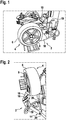
- Figure 1 shows a perspective front view of a bead breaker device 2 according to an exemplary embodiment of the invention together with a wheel 4.
- Figure 2 shows a perspective view of the bead breaker device 2 from the top.
- Figure 3 shows a perspective partial view of the functional parts of a bead breaker device 2 according to an exemplary embodiment of the invention including the bead breaker arm 12, and Figures 4 to 7 depict top views respectively corresponding to a different configuration / orientation of the bead breaker arm 12. For reasons of clarity, the wheel 4 is not shown in Figures 3 to 7 .
- the bead breaker device 2 comprises a support structure 10 supporting a rotatable reception or hub, which is not visible in the figures.
- the reception or hub is configured for receiving and supporting a rim 8 of a wheel 4.
- the reception or hub is rotatable so that the wheel 4, when mounted to the reception or hub, is rotatable around a rotational axis, which is coaxial with the axis of the wheel 4. In the embodiment shown in the figures the rotational axis is oriented horizontally.
- a bead breaker arm 12 comprises a first arm portion 13 including a first end 14 and a second arm portion 15 including an opposing second 16.
- the first and second arm portions 13, 15 are connected to each other at an obtuse angle, e.g. at an angle of 140° to 160°, in particular at an angle of 150°.
- the first end 14 is mounted to a rod 24 of the support structure 10 by means of a first joint 20 so that it is rotatable around a vertical axis, i.e. an axis which is oriented orthogonally with respect to the plane of Figures 4 to 7 .
- the first joint 20 is supported by a carriage 22, which is slidably mounted to the rod 24.
- the slidable carriage 22 allows the first joint 20 to move linearly in a direction, which is oriented basically parallel to the rotational axis.
- the distance of the first joint 20 from the support structure 10 may be adjusted by moving the carriage 22 along the rod 24 in a direction, which is oriented basically parallel to the rotational axis.
- a bead breaker pad 18 is mounted to the second end 16 of the bead breaker arm 12.
- the bead breaker pad 18 is configured to interact with the wheel 4 in order to separate the tyre 6 from the rim 8 of the wheel 4.
- the bead breaker pad 18 comprises a handle 19, which allows for a manual movement of the bead breaker pad 18.
- the bead breaker arm 12 further comprises a third arm portion 21 extending from the first arm portion 13 towards the support structure 10.
- the third arm portion 21 in particular may extend basically at an angle of 90° with respect to the second arm portion 15.
- a second joint 28 is provided at a distal end of the third arm portion 21 facing towards the support structure 10.
- An actuating rod 26 is pivotably connected to the third arm portion 21 by means of the second joint 28.
- An opposing end of the actuating rod 26 facing away from the bead breaker arm 12 interacts with an actuator 30 provided within or at the support structure 10. This configuration allows the actuator 30 to move the bead breaker arm 12 by actuating the actuating rod 26.
- the actuator 30 may be an electromagnetic, pneumatic or hydraulic actuator 30.
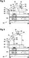
- Figures 4 and 5 depict a first configuration, in which the carriage 22 is arranged in a first position, in which the first joint 20 is arranged close to support structure 10.
- the bead breaker arm 12 is pivoted into an "open position", in which the second end 14 of the breaker arm 12 supporting the bead breaker pad 18 is arranged in a large distance D 1 from the support structure 10. This position allows mounting/dismounting a wheel 4 (not shown in Figs. 4 to 7 ) to/from the reception/hub.
- the minimum distance d 1 between the tip of the bead breaker pad 18 and the support structure 10 may be e.g. 60 mm.
- the bead breaker pad 18 interacts with a wheel 4 (not shown in Figs. 4 to 7 ) mounted to the reception/hub in order to separate the tyre 6 from the rim 8 of the wheel 4.
- the bead breaker pad 18 is oriented in an angle ⁇ 1 with respect to the front face of the support structure 10, which is parallel to the plane of rotation of the wheel 4.
- Figures 6 and 7 depict a second configuration, in which the carriage 22 is in a second, extended position, in which the first joint 20 is arranged in a larger distance form the support structure 10 than in the first position.
- the bead breaker arm 12 is pivoted into an "open position", in which the second end 14 of the breaker arm 12 supporting the bead breaker pad 18 is arranged in a larger distance D 2 from the support structure 10. This position allows mounting/dismounting a wheel 4 (not shown in Figure 4 ) to/from the reception.
- the distance D 2 is larger than the distance D 1 in the configuration shown in Figure 4 .
- wider wheels 4 may be mounted to the reception.
- the bead breaker arm 12 is pivoted into a "closed position", in which the second end 14 of the breaker arm 12 supporting the bead breaker pad 18 is arranged in a small distance d 2 from the support structure 10. In this position, the bead breaker pad 18 interacts with a wheel 4 (not shown) mounted to the reception/hub in order to separate the tyre 6 from the rim 8 of the wheel 4.
- the distance d 2 is smaller than the distance d 1 in the configuration shown in Figure 5 .
- the minimum distance d 2 between the tip of the breaker pad 18 and the support structure 10 may be reduced to e.g. 10 mm.
- the distance d 2 even may be zero.
- orientation of the bead breaker pad 18 with respect to the front face of the support structure 10 may change to a larger angle ⁇ 2 .
Landscapes
- Engineering & Computer Science (AREA)
- Mechanical Engineering (AREA)
- Tires In General (AREA)
Abstract
Description
- The invention relates to a bead breaker device for removing a tyre from a rim of a wheel.
- Bead breaker devices comprising a pivotable bead breaker arm for removing a tyre from a rim of a wheel are known in the art. These bead breaker devices, however, are not well suited for all kinds of wheels. Their performance depends on the width of the wheel and they are usually not optimal for removing tyres from very big/wide or small/narrow rims.
- It an object of the invention to provide an improved bead breaker device, in particular a bead breaker device, which is more effective in removing big/wide and small/narrow tyres.
- According to an exemplary embodiment of the invention, a bead breaker device for removing a tyre from a rim of a wheel comprises a support structure and a bead breaker arm, which is pivotably fixed to the support structure by means of a joint. Said joint is linearly movable with respect to the support structure.
- Allowing a linear movement of the joint with respect to the support structure adds an additional degree of freedom to the bead breaker arm providing more flexibility. Said additional flexibility allows adjusting the bead breaker arm better to different kinds of wheels, in particular to different sizes and shapes of wheels, tyres and/or rims.
- According to an embodiment of the invention, the bead breaker device has a first end and an opposing second end, and the bead breaker arm is pivotable between a closed position, in which the second end of the bead breaker arm is arranged close to the support structure, and an open position, in which the second end of the bead breaker arm is arranged in more distance from the support structure.
- The open position of the bead breaker arm allows mounting / dismounting a wheel to/from the bead breaker device.
- When arranged in the closed position, the bead breaker arm is in a position close to the wheel in order to remove the tyre from the rim.
- According to an embodiment, linear movement of the joint allows modifying the distance between the second end of the bead breaker arm and the support structure in the open and/or in the closed position of the bead breaker arm. This allows adjusting the position of the bead breaker arm to different sizes, in particular to different widths, of the rim.
- According to an embodiment, the bead breaker device comprises a rotatable reception or hub, which is configured for receiving and supporting a rim of a wheel. The reception or hub is rotatable so that the wheel, when mounted to the reception or hub, is rotatable around a rotational axis, which is coaxial with the axis of the wheel. This allows removing a tyre from a rim of the wheel by means of the bead breaker arm.
- According to an embodiment, the joint is slidable in a direction which is oriented parallel to the rotational axis. This allows adjusting the minimum distance and/or the angle between the second end of the bead breaker arm and the wheel.
- According to an embodiment the joint is a first joint and the bead breaker device additionally comprises a second joint pivotably connecting an actuating rod to the bead breaker arm. The second joint in particular is connected to the bead breaker arm at a location between the first and second ends of the bead breaker arm.
- According to an embodiment, the bead breaker device further comprises an actuator, which is configured for moving the actuation rod in order to move the bead breaker arm between its closed and open positions. The actuator may be an electromagnetic, pneumatic or hydraulic actuator. An actuator allows conveniently removing the tyre from the rim of the wheel by moving the bead breaker arm by means of the actuator.
- According to an embodiment, the bead breaker arm comprises a bead breaker pad which is provided at the second end of the bead breaker arm and which is configured for interacting with the tyre in order to remove the tyre from the rim. A bead breaker pad allows removing the tyre from the rim conveniently, reliably and securely without damaging the tyre and/or the rim.
- According to an embodiment, a linear movement of the first joint allows adjusting the angle between the bead breaker pad and the wheel. Adjusting the angle between the bead breaker pad and the wheel allows optimising the orientation of the bead breaker pad with respect to the wheel in order to remove the tyre from the rim most efficiently without causing damage to the tyre and/or to the rim.
- In the following an exemplary embodiment of the invention is described with respect to the enclosed figures.
-
-
Figure 1 shows a perspective front view of a bead breaker device according to an exemplary embodiment of the invention. -
Figure 2 shows a perspective view of the bead breaker device shown inFigure 1 from the top. -
Figure 3 shows a perspective partial view of the functional parts of a bead breaker device according to an exemplary embodiment of the invention. -
Figures 4 to 7 depict different top views respectively illustrating one of a plurality of configurations of the bead breaker arm. -
Figure 1 shows a perspective front view of abead breaker device 2 according to an exemplary embodiment of the invention together with a wheel 4.Figure 2 shows a perspective view of thebead breaker device 2 from the top. -
Figure 3 shows a perspective partial view of the functional parts of abead breaker device 2 according to an exemplary embodiment of the invention including thebead breaker arm 12, andFigures 4 to 7 depict top views respectively corresponding to a different configuration / orientation of thebead breaker arm 12. For reasons of clarity, the wheel 4 is not shown inFigures 3 to 7 . - The
bead breaker device 2 comprises asupport structure 10 supporting a rotatable reception or hub, which is not visible in the figures. The reception or hub is configured for receiving and supporting arim 8 of a wheel 4. The reception or hub is rotatable so that the wheel 4, when mounted to the reception or hub, is rotatable around a rotational axis, which is coaxial with the axis of the wheel 4. In the embodiment shown in the figures the rotational axis is oriented horizontally. - A
bead breaker arm 12 comprises afirst arm portion 13 including afirst end 14 and asecond arm portion 15 including an opposingsecond 16. The first andsecond arm portions - The
first end 14 is mounted to arod 24 of thesupport structure 10 by means of afirst joint 20 so that it is rotatable around a vertical axis, i.e. an axis which is oriented orthogonally with respect to the plane ofFigures 4 to 7 . - The
first joint 20 is supported by acarriage 22, which is slidably mounted to therod 24. Theslidable carriage 22 allows thefirst joint 20 to move linearly in a direction, which is oriented basically parallel to the rotational axis. As a result, the distance of thefirst joint 20 from thesupport structure 10 may be adjusted by moving thecarriage 22 along therod 24 in a direction, which is oriented basically parallel to the rotational axis. - A
bead breaker pad 18 is mounted to thesecond end 16 of thebead breaker arm 12. Thebead breaker pad 18 is configured to interact with the wheel 4 in order to separate the tyre 6 from therim 8 of the wheel 4. - The
bead breaker pad 18 comprises ahandle 19, which allows for a manual movement of thebead breaker pad 18. - The
bead breaker arm 12 further comprises athird arm portion 21 extending from thefirst arm portion 13 towards thesupport structure 10. Thethird arm portion 21 in particular may extend basically at an angle of 90° with respect to thesecond arm portion 15. - A
second joint 28 is provided at a distal end of thethird arm portion 21 facing towards thesupport structure 10. An actuatingrod 26 is pivotably connected to thethird arm portion 21 by means of thesecond joint 28. - An opposing end of the actuating
rod 26 facing away from thebead breaker arm 12 interacts with anactuator 30 provided within or at thesupport structure 10. This configuration allows theactuator 30 to move thebead breaker arm 12 by actuating the actuatingrod 26. - The
actuator 30 may be an electromagnetic, pneumatic orhydraulic actuator 30. -
Figures 4 and5 depict a first configuration, in which thecarriage 22 is arranged in a first position, in which thefirst joint 20 is arranged close to supportstructure 10. - In
Figure 4 , thebead breaker arm 12 is pivoted into an "open position", in which thesecond end 14 of thebreaker arm 12 supporting thebead breaker pad 18 is arranged in a large distance D1 from thesupport structure 10. This position allows mounting/dismounting a wheel 4 (not shown inFigs. 4 to 7 ) to/from the reception/hub. - In
Figure 5 , thebead breaker arm 12 is pivoted into a "closed position", in which thesecond end 14 of thebreaker arm 12 supporting thebead breaker pad 18 is arranged in a small distance d1 from thesupport structure 10. - The minimum distance d1 between the tip of the
bead breaker pad 18 and thesupport structure 10 may be e.g. 60 mm. - In this position, the
bead breaker pad 18 interacts with a wheel 4 (not shown inFigs. 4 to 7 ) mounted to the reception/hub in order to separate the tyre 6 from therim 8 of the wheel 4. In this position, thebead breaker pad 18 is oriented in an angle α1 with respect to the front face of thesupport structure 10, which is parallel to the plane of rotation of the wheel 4. -
Figures 6 and7 depict a second configuration, in which thecarriage 22 is in a second, extended position, in which the first joint 20 is arranged in a larger distance form thesupport structure 10 than in the first position. - In
Figure 6 , thebead breaker arm 12 is pivoted into an "open position", in which thesecond end 14 of thebreaker arm 12 supporting thebead breaker pad 18 is arranged in a larger distance D2 from thesupport structure 10. This position allows mounting/dismounting a wheel 4 (not shown inFigure 4 ) to/from the reception. The distance D2 is larger than the distance D1 in the configuration shown inFigure 4 . Thus, in this configuration, wider wheels 4 may be mounted to the reception. - In
Figure 7 , thebead breaker arm 12 is pivoted into a "closed position", in which thesecond end 14 of thebreaker arm 12 supporting thebead breaker pad 18 is arranged in a small distance d2 from thesupport structure 10. In this position, thebead breaker pad 18 interacts with a wheel 4 (not shown) mounted to the reception/hub in order to separate the tyre 6 from therim 8 of the wheel 4. - Due to the extended position of the
carriage 22, in this configuration the distance d2 is smaller than the distance d1 in the configuration shown inFigure 5 . The minimum distance d2 between the tip of thebreaker pad 18 and thesupport structure 10 may be reduced to e.g. 10 mm. The distance d2 even may be zero. - Additionally, the orientation of the
bead breaker pad 18 with respect to the front face of thesupport structure 10 may change to a larger angle α2. - The reduction of the minimum distance d1/2 and the change of the angle α1/2 increase the performance penetration of the
bead breaker pad 18 into the gap between therim 8 and the tyre 6. - This enhances the performance of the
bead breaker arm 12 in particular for small or wet tyres 6 and special shapes of therim 8. It further reduced the risk of damaging sensors (TMPS) provided inside the tyre 6.
Claims (10)
- Bead breaker device (2) for removing a tyre (8) from a rim (6) of a wheel (4), the bead breaker device (2) comprising:a support structure (10);a bead breaker arm (12) which is pivotably fixed to the support structure (10) by a joint (20);characterized in that
said joint (20) is linearly movable with respect to the support structure (10). - Bead breaker device (2) according to claim 1 having a first end (14) and an opposing second end (16), wherein the bead breaker arm (12) is pivotable between a closed position, in which the second end (16) of the bead breaker arm (12) is arranged in a position close to the support structure (10), and an open position, in which the second end (16) of the bead breaker arm (12) is arranged in a larger distance from the support structure (10).
- Bead breaker device (2) according to claim 2, wherein a linear movement of the joint (20) allows modifying the distance (D1, D2) between the second end (16) of the bead breaker arm (12) and the support structure (10) in its open position.
- Bead breaker device (2) according to claim 2 or 3, wherein a linear movement of the joint (20) allows modifying the distance (d1, d2) between the second end (16) of the bead breaker arm (12) and the support structure (10) in its closed position.
- Bead breaker device (2) according to any of the previous claims further comprising a rotatable reception or hub, which is configured to receive a rim (6) of wheel (4) so that the wheel (4) is rotatable around a rotational axis, which is coaxial with the axis of the wheel (4).
- Bead breaker device (2) according to claim 5, wherein the joint (20) slidable in a direction which is parallel to the rotational axis.
- Bead breaker device (2) according to any of the previous claims, further comprising a bead breaker pad (18), which is provided at the second end (16) of the bead breaker arm (12) and which is configured for interacting with the wheel (4) in order to remove the tyre (8) from the rim (6).
- Bead breaker device (2) according to claim 7, wherein a linear movement of the joint (20) allows modifying an angle (α) between the bead breaker pad (18) and the wheel (4).
- Bead breaker device (2) according to any of the previous claims wherein the joint (20) is a first joint (20) and the bead breaker device (2) tyre comprises a second joint (28) pivotably connecting an actuation rod (26) to the bead breaker arm (12).
- Bead breaker device (2) according to claim 9, further comprising an actuator (30), which is configured for moving the actuation rod (26) in order to move the bead breaker arm (12) between its closed position and an open position.
Priority Applications (2)
| Application Number | Priority Date | Filing Date | Title |
|---|---|---|---|
| EP17184495.4A EP3437901B1 (en) | 2017-08-02 | 2017-08-02 | Bead breaker device |
| PCT/EP2018/070587 WO2019025363A1 (en) | 2017-08-02 | 2018-07-30 | Bead breaker device |
Applications Claiming Priority (1)
| Application Number | Priority Date | Filing Date | Title |
|---|---|---|---|
| EP17184495.4A EP3437901B1 (en) | 2017-08-02 | 2017-08-02 | Bead breaker device |
Publications (2)
| Publication Number | Publication Date |
|---|---|
| EP3437901A1 true EP3437901A1 (en) | 2019-02-06 |
| EP3437901B1 EP3437901B1 (en) | 2020-05-13 |
Family
ID=59520811
Family Applications (1)
| Application Number | Title | Priority Date | Filing Date |
|---|---|---|---|
| EP17184495.4A Active EP3437901B1 (en) | 2017-08-02 | 2017-08-02 | Bead breaker device |
Country Status (2)
| Country | Link |
|---|---|
| EP (1) | EP3437901B1 (en) |
| WO (1) | WO2019025363A1 (en) |
Citations (3)
| Publication number | Priority date | Publication date | Assignee | Title |
|---|---|---|---|---|
| EP0015102A1 (en) * | 1979-02-22 | 1980-09-03 | Magnum Automotive Equipment, Inc. | Improved bead breaker mechanism for a tyre changer machine |
| JPS55176807U (en) * | 1979-06-06 | 1980-12-18 | ||
| EP1524134A1 (en) * | 2003-10-14 | 2005-04-20 | CORGHI S.p.A. | Bead release device for tire removal machines |
-
2017
- 2017-08-02 EP EP17184495.4A patent/EP3437901B1/en active Active
-
2018
- 2018-07-30 WO PCT/EP2018/070587 patent/WO2019025363A1/en not_active Ceased
Patent Citations (3)
| Publication number | Priority date | Publication date | Assignee | Title |
|---|---|---|---|---|
| EP0015102A1 (en) * | 1979-02-22 | 1980-09-03 | Magnum Automotive Equipment, Inc. | Improved bead breaker mechanism for a tyre changer machine |
| JPS55176807U (en) * | 1979-06-06 | 1980-12-18 | ||
| EP1524134A1 (en) * | 2003-10-14 | 2005-04-20 | CORGHI S.p.A. | Bead release device for tire removal machines |
Also Published As
| Publication number | Publication date |
|---|---|
| WO2019025363A1 (en) | 2019-02-07 |
| EP3437901B1 (en) | 2020-05-13 |
Similar Documents
| Publication | Publication Date | Title |
|---|---|---|
| CN100560392C (en) | Bead release unit for tire changing devices | |
| EP1897707A1 (en) | Bead breaking unit for tyre changing machines | |
| EP2816886B1 (en) | Robotic lawnmower | |
| EP2799627B1 (en) | A gripping organ for load-moving vehicles | |
| EP3466732B1 (en) | A vertical lifting system for use in farming machines | |
| US9752723B2 (en) | Display support device | |
| CN105083544A (en) | Rotary-wing drone of the quadricopter type, provided with removable bumpers for protecting the propellers | |
| US9415816B2 (en) | Spoiler device for vehicle | |
| CN101439650B (en) | Machine for fitting and removing wheel tires for vehicles | |
| CN105358345B (en) | Tyre changing machine for trucks | |
| US9162544B2 (en) | Tire changing machine with bead loosener arm | |
| US10252586B2 (en) | Tyre mounting/demounting tool | |
| EP3278930A1 (en) | Device for installing or removing a motor vehicle window pane | |
| WO2014045616A1 (en) | Wire gripper | |
| WO2016197241A1 (en) | Wheel lift | |
| US10517235B2 (en) | Apparatus for reducing plant material | |
| EP3437901A1 (en) | Bead breaker device | |
| WO2011146392A1 (en) | Traction device for a vehicle tire | |
| KR20140077117A (en) | Robot arm | |
| ITMO20110118A1 (en) | BREAKER GROUP FOR TIRE CHANGER MACHINES | |
| AU2020201964B2 (en) | Suspension caster | |
| FI124105B (en) | A method of attaching the lifting clone to the lifting arm of a lifting device and lifting device | |
| CN208343831U (en) | A kind of universal wheel and its walking arrangement of attitude reference device | |
| EP2894961B1 (en) | Swather with a single or double raking frame | |
| CN208774433U (en) | Equipment for installing and removing electronic components for tires |
Legal Events
| Date | Code | Title | Description |
|---|---|---|---|
| PUAI | Public reference made under article 153(3) epc to a published international application that has entered the european phase |
Free format text: ORIGINAL CODE: 0009012 |
|
| STAA | Information on the status of an ep patent application or granted ep patent |
Free format text: STATUS: THE APPLICATION HAS BEEN PUBLISHED |
|
| AK | Designated contracting states |
Kind code of ref document: A1 Designated state(s): AL AT BE BG CH CY CZ DE DK EE ES FI FR GB GR HR HU IE IS IT LI LT LU LV MC MK MT NL NO PL PT RO RS SE SI SK SM TR |
|
| AX | Request for extension of the european patent |
Extension state: BA ME |
|
| RAP1 | Party data changed (applicant data changed or rights of an application transferred) |
Owner name: BEISSBARTH GMBH |
|
| STAA | Information on the status of an ep patent application or granted ep patent |
Free format text: STATUS: REQUEST FOR EXAMINATION WAS MADE |
|
| 17P | Request for examination filed |
Effective date: 20190701 |
|
| RBV | Designated contracting states (corrected) |
Designated state(s): AL AT BE BG CH CY CZ DE DK EE ES FI FR GB GR HR HU IE IS IT LI LT LU LV MC MK MT NL NO PL PT RO RS SE SI SK SM TR |
|
| GRAP | Despatch of communication of intention to grant a patent |
Free format text: ORIGINAL CODE: EPIDOSNIGR1 |
|
| STAA | Information on the status of an ep patent application or granted ep patent |
Free format text: STATUS: GRANT OF PATENT IS INTENDED |
|
| INTG | Intention to grant announced |
Effective date: 20191213 |
|
| GRAS | Grant fee paid |
Free format text: ORIGINAL CODE: EPIDOSNIGR3 |
|
| GRAA | (expected) grant |
Free format text: ORIGINAL CODE: 0009210 |
|
| STAA | Information on the status of an ep patent application or granted ep patent |
Free format text: STATUS: THE PATENT HAS BEEN GRANTED |
|
| AK | Designated contracting states |
Kind code of ref document: B1 Designated state(s): AL AT BE BG CH CY CZ DE DK EE ES FI FR GB GR HR HU IE IS IT LI LT LU LV MC MK MT NL NO PL PT RO RS SE SI SK SM TR |
|
| REG | Reference to a national code |
Ref country code: GB Ref legal event code: FG4D |
|
| REG | Reference to a national code |
Ref country code: CH Ref legal event code: EP |
|
| REG | Reference to a national code |
Ref country code: DE Ref legal event code: R096 Ref document number: 602017016358 Country of ref document: DE |
|
| REG | Reference to a national code |
Ref country code: AT Ref legal event code: REF Ref document number: 1269785 Country of ref document: AT Kind code of ref document: T Effective date: 20200615 |
|
| REG | Reference to a national code |
Ref country code: LT Ref legal event code: MG4D |
|
| REG | Reference to a national code |
Ref country code: NL Ref legal event code: MP Effective date: 20200513 |
|
| PG25 | Lapsed in a contracting state [announced via postgrant information from national office to epo] |
Ref country code: IS Free format text: LAPSE BECAUSE OF FAILURE TO SUBMIT A TRANSLATION OF THE DESCRIPTION OR TO PAY THE FEE WITHIN THE PRESCRIBED TIME-LIMIT Effective date: 20200913 Ref country code: PT Free format text: LAPSE BECAUSE OF FAILURE TO SUBMIT A TRANSLATION OF THE DESCRIPTION OR TO PAY THE FEE WITHIN THE PRESCRIBED TIME-LIMIT Effective date: 20200914 Ref country code: SE Free format text: LAPSE BECAUSE OF FAILURE TO SUBMIT A TRANSLATION OF THE DESCRIPTION OR TO PAY THE FEE WITHIN THE PRESCRIBED TIME-LIMIT Effective date: 20200513 Ref country code: FI Free format text: LAPSE BECAUSE OF FAILURE TO SUBMIT A TRANSLATION OF THE DESCRIPTION OR TO PAY THE FEE WITHIN THE PRESCRIBED TIME-LIMIT Effective date: 20200513 Ref country code: NO Free format text: LAPSE BECAUSE OF FAILURE TO SUBMIT A TRANSLATION OF THE DESCRIPTION OR TO PAY THE FEE WITHIN THE PRESCRIBED TIME-LIMIT Effective date: 20200813 Ref country code: LT Free format text: LAPSE BECAUSE OF FAILURE TO SUBMIT A TRANSLATION OF THE DESCRIPTION OR TO PAY THE FEE WITHIN THE PRESCRIBED TIME-LIMIT Effective date: 20200513 |
|
| PG25 | Lapsed in a contracting state [announced via postgrant information from national office to epo] |
Ref country code: RS Free format text: LAPSE BECAUSE OF FAILURE TO SUBMIT A TRANSLATION OF THE DESCRIPTION OR TO PAY THE FEE WITHIN THE PRESCRIBED TIME-LIMIT Effective date: 20200513 Ref country code: LV Free format text: LAPSE BECAUSE OF FAILURE TO SUBMIT A TRANSLATION OF THE DESCRIPTION OR TO PAY THE FEE WITHIN THE PRESCRIBED TIME-LIMIT Effective date: 20200513 Ref country code: BG Free format text: LAPSE BECAUSE OF FAILURE TO SUBMIT A TRANSLATION OF THE DESCRIPTION OR TO PAY THE FEE WITHIN THE PRESCRIBED TIME-LIMIT Effective date: 20200813 Ref country code: HR Free format text: LAPSE BECAUSE OF FAILURE TO SUBMIT A TRANSLATION OF THE DESCRIPTION OR TO PAY THE FEE WITHIN THE PRESCRIBED TIME-LIMIT Effective date: 20200513 |
|
| REG | Reference to a national code |
Ref country code: AT Ref legal event code: MK05 Ref document number: 1269785 Country of ref document: AT Kind code of ref document: T Effective date: 20200513 |
|
| PG25 | Lapsed in a contracting state [announced via postgrant information from national office to epo] |
Ref country code: NL Free format text: LAPSE BECAUSE OF FAILURE TO SUBMIT A TRANSLATION OF THE DESCRIPTION OR TO PAY THE FEE WITHIN THE PRESCRIBED TIME-LIMIT Effective date: 20200513 Ref country code: AL Free format text: LAPSE BECAUSE OF FAILURE TO SUBMIT A TRANSLATION OF THE DESCRIPTION OR TO PAY THE FEE WITHIN THE PRESCRIBED TIME-LIMIT Effective date: 20200513 |
|
| PG25 | Lapsed in a contracting state [announced via postgrant information from national office to epo] |
Ref country code: RO Free format text: LAPSE BECAUSE OF FAILURE TO SUBMIT A TRANSLATION OF THE DESCRIPTION OR TO PAY THE FEE WITHIN THE PRESCRIBED TIME-LIMIT Effective date: 20200513 Ref country code: SM Free format text: LAPSE BECAUSE OF FAILURE TO SUBMIT A TRANSLATION OF THE DESCRIPTION OR TO PAY THE FEE WITHIN THE PRESCRIBED TIME-LIMIT Effective date: 20200513 Ref country code: EE Free format text: LAPSE BECAUSE OF FAILURE TO SUBMIT A TRANSLATION OF THE DESCRIPTION OR TO PAY THE FEE WITHIN THE PRESCRIBED TIME-LIMIT Effective date: 20200513 Ref country code: DK Free format text: LAPSE BECAUSE OF FAILURE TO SUBMIT A TRANSLATION OF THE DESCRIPTION OR TO PAY THE FEE WITHIN THE PRESCRIBED TIME-LIMIT Effective date: 20200513 Ref country code: AT Free format text: LAPSE BECAUSE OF FAILURE TO SUBMIT A TRANSLATION OF THE DESCRIPTION OR TO PAY THE FEE WITHIN THE PRESCRIBED TIME-LIMIT Effective date: 20200513 Ref country code: CZ Free format text: LAPSE BECAUSE OF FAILURE TO SUBMIT A TRANSLATION OF THE DESCRIPTION OR TO PAY THE FEE WITHIN THE PRESCRIBED TIME-LIMIT Effective date: 20200513 Ref country code: ES Free format text: LAPSE BECAUSE OF FAILURE TO SUBMIT A TRANSLATION OF THE DESCRIPTION OR TO PAY THE FEE WITHIN THE PRESCRIBED TIME-LIMIT Effective date: 20200513 |
|
| REG | Reference to a national code |
Ref country code: DE Ref legal event code: R097 Ref document number: 602017016358 Country of ref document: DE |
|
| PG25 | Lapsed in a contracting state [announced via postgrant information from national office to epo] |
Ref country code: SK Free format text: LAPSE BECAUSE OF FAILURE TO SUBMIT A TRANSLATION OF THE DESCRIPTION OR TO PAY THE FEE WITHIN THE PRESCRIBED TIME-LIMIT Effective date: 20200513 Ref country code: PL Free format text: LAPSE BECAUSE OF FAILURE TO SUBMIT A TRANSLATION OF THE DESCRIPTION OR TO PAY THE FEE WITHIN THE PRESCRIBED TIME-LIMIT Effective date: 20200513 |
|
| PLBE | No opposition filed within time limit |
Free format text: ORIGINAL CODE: 0009261 |
|
| STAA | Information on the status of an ep patent application or granted ep patent |
Free format text: STATUS: NO OPPOSITION FILED WITHIN TIME LIMIT |
|
| PG25 | Lapsed in a contracting state [announced via postgrant information from national office to epo] |
Ref country code: MC Free format text: LAPSE BECAUSE OF FAILURE TO SUBMIT A TRANSLATION OF THE DESCRIPTION OR TO PAY THE FEE WITHIN THE PRESCRIBED TIME-LIMIT Effective date: 20200513 |
|
| REG | Reference to a national code |
Ref country code: CH Ref legal event code: PL |
|
| 26N | No opposition filed |
Effective date: 20210216 |
|
| PG25 | Lapsed in a contracting state [announced via postgrant information from national office to epo] |
Ref country code: CH Free format text: LAPSE BECAUSE OF NON-PAYMENT OF DUE FEES Effective date: 20200831 Ref country code: LI Free format text: LAPSE BECAUSE OF NON-PAYMENT OF DUE FEES Effective date: 20200831 Ref country code: LU Free format text: LAPSE BECAUSE OF NON-PAYMENT OF DUE FEES Effective date: 20200802 |
|
| REG | Reference to a national code |
Ref country code: BE Ref legal event code: MM Effective date: 20200831 |
|
| PG25 | Lapsed in a contracting state [announced via postgrant information from national office to epo] |
Ref country code: SI Free format text: LAPSE BECAUSE OF FAILURE TO SUBMIT A TRANSLATION OF THE DESCRIPTION OR TO PAY THE FEE WITHIN THE PRESCRIBED TIME-LIMIT Effective date: 20200513 |
|
| REG | Reference to a national code |
Ref country code: DE Ref legal event code: R082 Ref document number: 602017016358 Country of ref document: DE Representative=s name: SCHMITT-NILSON SCHRAUD WAIBEL WOHLFROM PATENTA, DE Ref country code: DE Ref legal event code: R081 Ref document number: 602017016358 Country of ref document: DE Owner name: SICAM S.R.I., IT Free format text: FORMER OWNER: BEISSBARTH GMBH, 80993 MUENCHEN, DE |
|
| REG | Reference to a national code |
Ref country code: GB Ref legal event code: 732E Free format text: REGISTERED BETWEEN 20210715 AND 20210721 |
|
| PG25 | Lapsed in a contracting state [announced via postgrant information from national office to epo] |
Ref country code: IE Free format text: LAPSE BECAUSE OF NON-PAYMENT OF DUE FEES Effective date: 20200802 Ref country code: BE Free format text: LAPSE BECAUSE OF NON-PAYMENT OF DUE FEES Effective date: 20200831 |
|
| PGFP | Annual fee paid to national office [announced via postgrant information from national office to epo] |
Ref country code: FR Payment date: 20210823 Year of fee payment: 5 |
|
| PGFP | Annual fee paid to national office [announced via postgrant information from national office to epo] |
Ref country code: GB Payment date: 20210824 Year of fee payment: 5 |
|
| PGFP | Annual fee paid to national office [announced via postgrant information from national office to epo] |
Ref country code: DE Payment date: 20211027 Year of fee payment: 5 |
|
| PG25 | Lapsed in a contracting state [announced via postgrant information from national office to epo] |
Ref country code: TR Free format text: LAPSE BECAUSE OF FAILURE TO SUBMIT A TRANSLATION OF THE DESCRIPTION OR TO PAY THE FEE WITHIN THE PRESCRIBED TIME-LIMIT Effective date: 20200513 Ref country code: MT Free format text: LAPSE BECAUSE OF FAILURE TO SUBMIT A TRANSLATION OF THE DESCRIPTION OR TO PAY THE FEE WITHIN THE PRESCRIBED TIME-LIMIT Effective date: 20200513 Ref country code: CY Free format text: LAPSE BECAUSE OF FAILURE TO SUBMIT A TRANSLATION OF THE DESCRIPTION OR TO PAY THE FEE WITHIN THE PRESCRIBED TIME-LIMIT Effective date: 20200513 |
|
| PG25 | Lapsed in a contracting state [announced via postgrant information from national office to epo] |
Ref country code: MK Free format text: LAPSE BECAUSE OF FAILURE TO SUBMIT A TRANSLATION OF THE DESCRIPTION OR TO PAY THE FEE WITHIN THE PRESCRIBED TIME-LIMIT Effective date: 20200513 |
|
| PG25 | Lapsed in a contracting state [announced via postgrant information from national office to epo] |
Ref country code: GR Free format text: LAPSE BECAUSE OF FAILURE TO SUBMIT A TRANSLATION OF THE DESCRIPTION OR TO PAY THE FEE WITHIN THE PRESCRIBED TIME-LIMIT Effective date: 20200513 |
|
| PGFP | Annual fee paid to national office [announced via postgrant information from national office to epo] |
Ref country code: IT Payment date: 20220831 Year of fee payment: 6 |
|
| REG | Reference to a national code |
Ref country code: DE Ref legal event code: R119 Ref document number: 602017016358 Country of ref document: DE |
|
| GBPC | Gb: european patent ceased through non-payment of renewal fee |
Effective date: 20220802 |
|
| PG25 | Lapsed in a contracting state [announced via postgrant information from national office to epo] |
Ref country code: FR Free format text: LAPSE BECAUSE OF NON-PAYMENT OF DUE FEES Effective date: 20220831 Ref country code: DE Free format text: LAPSE BECAUSE OF NON-PAYMENT OF DUE FEES Effective date: 20230301 |
|
| PG25 | Lapsed in a contracting state [announced via postgrant information from national office to epo] |
Ref country code: GB Free format text: LAPSE BECAUSE OF NON-PAYMENT OF DUE FEES Effective date: 20220802 |
|
| PG25 | Lapsed in a contracting state [announced via postgrant information from national office to epo] |
Ref country code: IT Free format text: LAPSE BECAUSE OF NON-PAYMENT OF DUE FEES Effective date: 20230802 |