EP3437868A1 - Ink jet head and ink jet recording apparatus - Google Patents
Ink jet head and ink jet recording apparatus Download PDFInfo
- Publication number
- EP3437868A1 EP3437868A1 EP17774225.1A EP17774225A EP3437868A1 EP 3437868 A1 EP3437868 A1 EP 3437868A1 EP 17774225 A EP17774225 A EP 17774225A EP 3437868 A1 EP3437868 A1 EP 3437868A1
- Authority
- EP
- European Patent Office
- Prior art keywords
- ink
- ink jet
- communication flow
- flow paths
- jet head
- Prior art date
- Legal status (The legal status is an assumption and is not a legal conclusion. Google has not performed a legal analysis and makes no representation as to the accuracy of the status listed.)
- Granted
Links
Images








Classifications
-
- B—PERFORMING OPERATIONS; TRANSPORTING
- B41—PRINTING; LINING MACHINES; TYPEWRITERS; STAMPS
- B41J—TYPEWRITERS; SELECTIVE PRINTING MECHANISMS, i.e. MECHANISMS PRINTING OTHERWISE THAN FROM A FORME; CORRECTION OF TYPOGRAPHICAL ERRORS
- B41J2/00—Typewriters or selective printing mechanisms characterised by the printing or marking process for which they are designed
- B41J2/005—Typewriters or selective printing mechanisms characterised by the printing or marking process for which they are designed characterised by bringing liquid or particles selectively into contact with a printing material
- B41J2/01—Ink jet
- B41J2/135—Nozzles
- B41J2/14—Structure thereof only for on-demand ink jet heads
- B41J2/1433—Structure of nozzle plates
-
- B—PERFORMING OPERATIONS; TRANSPORTING
- B41—PRINTING; LINING MACHINES; TYPEWRITERS; STAMPS
- B41J—TYPEWRITERS; SELECTIVE PRINTING MECHANISMS, i.e. MECHANISMS PRINTING OTHERWISE THAN FROM A FORME; CORRECTION OF TYPOGRAPHICAL ERRORS
- B41J2/00—Typewriters or selective printing mechanisms characterised by the printing or marking process for which they are designed
- B41J2/005—Typewriters or selective printing mechanisms characterised by the printing or marking process for which they are designed characterised by bringing liquid or particles selectively into contact with a printing material
- B41J2/01—Ink jet
- B41J2/135—Nozzles
- B41J2/14—Structure thereof only for on-demand ink jet heads
- B41J2/14201—Structure of print heads with piezoelectric elements
- B41J2/14209—Structure of print heads with piezoelectric elements of finger type, chamber walls consisting integrally of piezoelectric material
-
- B—PERFORMING OPERATIONS; TRANSPORTING
- B41—PRINTING; LINING MACHINES; TYPEWRITERS; STAMPS
- B41J—TYPEWRITERS; SELECTIVE PRINTING MECHANISMS, i.e. MECHANISMS PRINTING OTHERWISE THAN FROM A FORME; CORRECTION OF TYPOGRAPHICAL ERRORS
- B41J2/00—Typewriters or selective printing mechanisms characterised by the printing or marking process for which they are designed
- B41J2/005—Typewriters or selective printing mechanisms characterised by the printing or marking process for which they are designed characterised by bringing liquid or particles selectively into contact with a printing material
- B41J2/01—Ink jet
- B41J2/135—Nozzles
- B41J2/14—Structure thereof only for on-demand ink jet heads
-
- B—PERFORMING OPERATIONS; TRANSPORTING
- B41—PRINTING; LINING MACHINES; TYPEWRITERS; STAMPS
- B41J—TYPEWRITERS; SELECTIVE PRINTING MECHANISMS, i.e. MECHANISMS PRINTING OTHERWISE THAN FROM A FORME; CORRECTION OF TYPOGRAPHICAL ERRORS
- B41J2/00—Typewriters or selective printing mechanisms characterised by the printing or marking process for which they are designed
- B41J2/005—Typewriters or selective printing mechanisms characterised by the printing or marking process for which they are designed characterised by bringing liquid or particles selectively into contact with a printing material
- B41J2/01—Ink jet
- B41J2/135—Nozzles
- B41J2/16—Production of nozzles
- B41J2/1607—Production of print heads with piezoelectric elements
- B41J2/1609—Production of print heads with piezoelectric elements of finger type, chamber walls consisting integrally of piezoelectric material
-
- B—PERFORMING OPERATIONS; TRANSPORTING
- B41—PRINTING; LINING MACHINES; TYPEWRITERS; STAMPS
- B41J—TYPEWRITERS; SELECTIVE PRINTING MECHANISMS, i.e. MECHANISMS PRINTING OTHERWISE THAN FROM A FORME; CORRECTION OF TYPOGRAPHICAL ERRORS
- B41J2/00—Typewriters or selective printing mechanisms characterised by the printing or marking process for which they are designed
- B41J2/005—Typewriters or selective printing mechanisms characterised by the printing or marking process for which they are designed characterised by bringing liquid or particles selectively into contact with a printing material
- B41J2/01—Ink jet
- B41J2/135—Nozzles
- B41J2/16—Production of nozzles
- B41J2/1621—Manufacturing processes
- B41J2/1623—Manufacturing processes bonding and adhesion
-
- B—PERFORMING OPERATIONS; TRANSPORTING
- B41—PRINTING; LINING MACHINES; TYPEWRITERS; STAMPS
- B41J—TYPEWRITERS; SELECTIVE PRINTING MECHANISMS, i.e. MECHANISMS PRINTING OTHERWISE THAN FROM A FORME; CORRECTION OF TYPOGRAPHICAL ERRORS
- B41J2/00—Typewriters or selective printing mechanisms characterised by the printing or marking process for which they are designed
- B41J2/005—Typewriters or selective printing mechanisms characterised by the printing or marking process for which they are designed characterised by bringing liquid or particles selectively into contact with a printing material
- B41J2/01—Ink jet
- B41J2/17—Ink jet characterised by ink handling
- B41J2/18—Ink recirculation systems
Definitions
- the present invention relates to an ink jet head and an ink jet recording apparatus.
- Ink jet recording apparatuses have been known in the art which form an image on a recording medium by jetting ink droplets from nozzles of an ink jet head.
- ink jet recording apparatuses single-pass printing of conveying a recording medium through a fixed ink jet head is known to have particularly high productivity.
- a maintenance work is required to remove such bubbles and foreign matters.
- the productivity is greatly deteriorated.
- ink jet recording apparatuses known in the art have a flow path in a head chip of an ink jet head, which can circulate ink to remove bubbles and the like near the nozzles without any additional maintenance work.
- Patent Document 1 discloses an ink jet head that includes a pressure chamber for storing ink to be jetted from nozzles and a communication flow path (high impedance channel) connected to the vicinity of the nozzles.
- the ink jet head the ink flows toward the nozzles through the communication flow path so that bubbles and the like near the nozzles can be discharged to a manifold through the pressure chamber.
- Patent Document 2 discloses an ink jet head that includes pressure chambers that stores ink to be jetted through nozzles and that is defined by a partition wall of a piezoelectric material, individual communication flow paths connected to the vicinities of the nozzles, a common communication flow path that joins ink from the individual communication flow paths together, and a flow path for discharging the ink out of a head.
- the individual communication flow paths and a common communication flow path are disposed on a base board on which the nozzles are mounted, and bubbles and the like near the nozzles can be discharged out of the ink jet head through the flow paths along with the ink.
- Patent Document 1 and Patent Document 2 can remove bubbles and the like near the nozzles while jetting ink from the nozzles. This can prevent deterioration of the productivity caused by an additional maintenance work.
- the ink jet head of Patent Document 1 requires providing the communication flow path (high impedance channel) and the pressure chamber having relatively large volume in a head chip. Accordingly, a problem is the increased size when the ink jet head includes a number of nozzles. Particularly in an ink jet recording apparatus (see FIG. 1 ) that performs continuous printing on recording media with a rotating drum and a fixed ink jet head, it is difficult to keep a constant distance between a recording medium and nozzles of the ink jet head and to perform high definition printing when the size of the ink jet head is large. Therefore, there is a need for reducing the size of the ink jet head. It is desirable to reduce the size of the ink jet head also in terms of the increased production cost due to increased materials for production and a reduction in size of the apparatus.
- the ink jet head of Patent Document 2 can be reduced in size since the flow paths are disposed on the base board of the nozzles.
- the individual communication flow paths and the common communication flow path are formed only in a narrow area in the base board of the nozzles, it is difficult to reduce the flow resistance of the flow paths. Therefore, it is therefore difficult to generate circulation flow of ink that is sufficient to discharge bubbles and the like.
- the present invention has been made in view of these problems, and an object thereof is to provide an ink jet head and an ink jet recording apparatus that can be reduced in size and that have a flow path capable of effectively discharging bubbles and the like.
- an ink jet head including:
- the invention according to claim 2 is the ink jet head according to claim 1, wherein a width in an ink jetting direction of the common communication flow path is greater than a thickness of the nozzle layer.
- the invention according to claim 3 is the ink jet head according to claim 1 or 2, wherein the individual communication flow paths are disposed in a part facing the pressure chamber layer of the nozzle layer.
- the invention according to claim 4 is the ink jet head according to any one of claims 1 to 3, wherein the pressure chamber layer comprises a discharge flow path which is communicated with the common communication flow path and which is capable of discharging the ink toward an opposite side from the nozzle layer.
- the invention according to claim 5 is the ink jet head according to any one of claims 1 to 4, wherein a sealing member is provided in the common communication flow path at an end in a longitudinal direction of the head chip.
- the invention according to claim 6 is the ink jet head according to any one of claims 1 to 4, wherein a width in an ink jetting direction of the common communication flow path decreases toward an end in the longitudinal direction of the head chip so that an upper face and a lower face come together to seal the common communication flow path.
- the invention according to claim 7 is the ink jet head according to any one of claims 1 to 6, wherein the manifold is disposed above the pressure chambers.
- the invention according to claim 8 is the ink jet head according to any one of claims 1 to 7, wherein the pressure chambers are partitioned from each other by a partition wall that causes share-mode displacement when a voltage is applied.
- the invention according to claim 9 is an ink jet recording apparatus, including:
- an ink jet head and an ink jet recording apparatus that can be reduced in size and that has a flow path capable of effectively discharging bubbles and the like.
- the array direction of nozzles 11a of an ink jet head 100 is referred to as the right-left direction (see FIG. 2 , FIG. 6 and FIG. 7 ), the ink jetting direction is referred to as the up-down direction, and the direction perpendicular to both right-left direction and up-down direction is referred to as the front-rear direction.
- the arrows in the flow paths in the drawings represent the flow direction of ink.
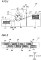
- an ink jet recording apparatus 200 includes a sheet feeder 210, an image recorder 220, a sheet ejector 230 and an ink circulating mechanism 8 (see FIG. 18 ) and the like.
- the ink jet recording apparatus 200 conveys a recording medium M stored in the sheet feeder 210 to the image recorder 220, forms an image on the recording medium M with the image recorder 220 and conveys the recording medium M with the image formed thereon to the sheet ejector 230.
- Recording media M that can be used include a variety of media which can fix ink landed on the surface, such as fabric and sheet resin as well as paper such as normal paper and coated paper.
- the sheet feeder 210 includes a sheet feeding tray 211 for storing the recording medium M and a medium feeder 212 that conveys and feeds the recording medium M from the sheet feeding tray 211 to the image recorder 220.
- the medium feeder 212 which includes a ring belt supported from inside by two rollers, conveys the recording medium M from the sheet feeding tray 211 to the image recorder 220 by rotating the rollers when the recording medium M is mounted on the belt.
- the image recorder 220 includes a conveyance drum 221, a handover unit 222, a heater 223, head units 224, a fixer 225, a deliverer 226 and the like.
- the conveyance drum 221 has a cylindrical surface, and the outer peripheral surface serves as a conveyance surface on which the recording medium M is mounted.
- the conveyance drum 221 conveys the recording medium M along the conveyance surface by rotating in the arrow direction in FIG. 1 when the recording medium M is held on the conveyance surface.
- the conveyance drum 221 includes hooks and suctioning parts (not shown). The hooks fix an end of the recording medium M, and the suctioning parts suction the recording medium M on the conveyance surface, so that the recording medium M is held on the conveyance surface.
- the handover unit 222 which is disposed between the medium feeder 212 of the sheet feeder 210 and the conveyance drum 221, catches and picks up an end of the recording medium M conveyed from the medium feeder 212 with a swing arm 222a and hands it over to the conveyance drum 221 via the handover drum 222b.
- the heater 223, which is disposed between the position of the handover drum 222b and the position of the head units 224, heats the recording medium M conveyed from the conveyance drum 221 so that the temperature of the recording medium M falls within a predetermined temperature range.
- the heater 223, which includes, for example, an infrared heater and the like, applies electricity to the infrared heater according to a control signal supplied from the hardware processor (not shown) to generate heat.
- the head units 224 jet ink to the recording medium M based on image data at a suitable timing in synchronization with the rotation of the conveyance drum 221 on which the recording medium M is held, so as to form an image.
- the head units 224 is disposed such that ink jetting surfaces are opposed to the conveyance drum 221 at a predetermined distance.
- four head units 224 corresponding respectively to the four colors of yellow (Y), magenta (M), cyan (C) and black (K) are aligned at predetermined intervals in the order of Y, M, C and K from the upstream of the conveyance direction of the recording medium M.
- pairs of ink jet heads 100 are arranged in a staggered pattern that staggers in the front-rear direction as illustrated in the bottom view in FIG. 2 .
- the array width in the right-left direction of the nozzles 11a of the ink jet heads 100 is equal to or greater than the width of an image forming area of the recording medium M.
- the head units 224 are fixed relative to the rotation axis of the conveyance drum 221 when an image is being recorded. That is, the ink jet recording apparatus 200 records an image by single-pass printing with the line heads.
- the ink to be jetted from the nozzles 11a of the ink jet heads 100 has the characteristics of causing phase transition between gel and sol depending on temperature and curing by energy ray such as ultraviolet ray.
- the ink that is used in the embodiment is in gel state at ordinary temperature but turns into solution when heated.
- the head units 224 include ink heaters (not shown) for heating the ink stored in the head units 224.
- the ink heaters can heat the ink to a temperature at which the ink is in solution state.
- the ink jet heads 100 jet the heated solution ink. When the solution ink is jetted to the recording medium M, ink droplets that are landed on the recording medium M are naturally cooled to rapidly turn into gel. The ink is thus solidified on the recording medium M.
- the fixer 225 which includes a light emitter disposed over the conveyance drum 221 in the X direction, emits an energy ray such as ultraviolet ray from the light emitter to the recording medium M mounted on the conveyance drum 221 so as to cure and fix the ink jetted on the recording medium M.
- the light emitter of the fixer 225 is disposed opposite to the conveyance surface in the downstream of the position of the head units 224 and the upstream of the position of a handover drum 226a of the deliverer 226 with respect to the conveyance direction.
- the deliverer 226 includes a belt loop 226b with a ring belt supported from inside by two rollers, and the cylindrical handover drum 226a that hands over the recording medium M from the conveyance drum 221 to the belt loop 226b.
- the belt loop 226b conveys the recording medium M toward the sheet ejector 230, which has been handed over from the conveyance drum 221 onto the belt loop 226b by the handover drum 226a.
- the sheet ejector 230 includes a sheet ejecting tray 231 having a plate shape on which the recording medium P sent from the image recorder 220 by the deliverer 226 is placed.
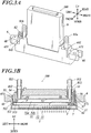
- FIG. 3A is a perspective view of an ink jet head 100 of the embodiment in which the present invention is implemented
- FIG. 3B is a cross-sectional view of the ink jet head 100
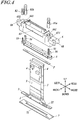
- FIG. 4 is an exploded perspective view of the ink jet head 100.
- a manifold 5 is not shown in FIG. 3A
- a cover member 9 is not shown in FIG. 3B and FIG. 4 .
- This embodiment is an example in which the head chip 1 has two nozzle lines.
- the number of lines and the arrangement of the nozzles 11a can be suitably changed.
- the head chip 1 may also have a single line, or three or more lines.
- each of the ink jet heads 100 of the embodiment includes the head chip 1, a wiring board 2 on which the head chip 1 is disposed, driver circuit boards 4 connected via the wiring board 2 and flexible boards 3, the manifold 5 that stores the ink to be supplied to pressure chambers 13A in the head chip 1, a case 6 in which the manifold 5 is housed, a cap receiver plate 7 that is attached to close a bottom opening of the case 6, the cover member 9 that is attached to the case 6, and the like.
- the head chip 1 has an approximately square pillar shape that is long in the right-left direction.
- the head chip 1 is composed of a nozzle layer 11 and a pressure chamber layer 12 (see FIG. 6 and FIG. 7 ).
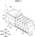
- FIG. 7 to FIG. 13 schematically illustrate an enlargement of a part of the head chip 1, but the portion at the left end of the head chip 1 is not shown in the figures.
- the pressure chamber layer 12 includes the pressure chambers 13A, discharge flow paths 13B and common communication flow paths 19.
- the pressure chambers 13A which are separated from each other by partition walls of a piezoelectric material, store the ink to be jetted from the nozzles 11a.
- a driver electrode 14 is provided in an inner wall of each of the pressure chambers 13A to move a partition wall between adjacent pressure chambers 13A.
- the driver electrode 14 is constituted by a metal film.
- Each of the pressure chambers 13A which has an approximately rectangular cross section, extends in the up-down direction and has an inlet in the top surface of the pressure chamber layer 12 and an out let in the bottom surface.
- Each of the pressure chambers 13A is a straight-type chamber that has approximately uniform size and the shape in the longitudinal direction (up-down direction) from the inlet to the outlet.
- the pressure chambers 13A are disposed parallel to each other.
- the pressure chambers 13A are arrayed in the right-left direction such that they form two lines adjacent in the front-rear direction.
- the driver electrodes 14 are not shown.
- the discharge flow paths 13B which are defined by partition walls as with the pressure chambers 13A, are provided to discharge the ink upward (to the opposite side from the nozzle layer 11) out of the ink jet heads 100.
- the discharge flow paths 13B extends in the up-down direction and has outlets in the top surface of the pressure chamber layer 12 and inlets in the bottom surface.
- the discharge flow paths 13B are straight-type paths that have approximately the same size and the shape in the longitudinal direction (up-down direction) from the inlets to the outlets.
- Two discharge flow paths 13B are disposed near the right end of the head chip 1 parallel to the pressure chambers 13A.
- the discharge flow paths 13B have a volume that is greater than the volume of the pressure chambers 13A as illustrated in FIG. 6 , FIG. 10 and FIG. 11 in order to improve the efficiency of discharging the ink.
- the common communication flow paths 19 are disposed in the part facing the nozzle layer 11 of the pressure chamber layer 12.
- the common communication flow paths 19 are connected to individual communication flow paths 18 which are further connected to the pressure chambers 13A, so that the ink flowing through the individual communication flow paths 18 joins together.
- the common communication flow paths 19 are disposed in the right-left direction for the respective nozzle lines, which are communicated with the discharge flow paths 13B near the right ends of the common flow paths (see FIG. 6 , FIG. 7 and FIG. 11 ).
- the width in the up-down direction of the common communication flow paths 19 can be greater than the thickness of the nozzle layer 11.
- the common communication flow paths 19 with a large volume can increase the amount of ink circulated in the head chip 1. This allows efficient discharge of bubbles and the like. Further, this allows efficient heat dissipation from the head chip 1.
- the nozzle layer 11 is constituted by a rectangular plate member, which is disposed on the bottom surface of the pressure chamber layer 12 to close lower ends of the pressure chambers 13A and the discharge flow paths 13B.
- the nozzle layer 11 includes the nozzles 11a and the individual communication flow paths 18 and the like.
- the nozzles 11a which are disposed opposite to the respective pressure chambers 13A, penetrate the nozzle layer 11 in the thickness direction (up-down direction) so as to jet the ink stored in the communicated pressure chambers 13A.
- the nozzles 11a are arrayed in the right-left direction. Further, the nozzles 11a form two lines adjacent in the front-rear direction.
- the individual communication flow paths 18 are disposed in the part facing the pressure chamber layer 12 of the nozzle layer 11, which extend in the front-rear direction from the nozzles 11a to the common communication flow paths 19 so as to communicate the pressure chambers 13A with the common communication flow paths 19 (see FIG. 8 , FIG. 13 and the like).
- one common communication flow path 19 is provided with respect to each of the nozzle lines, and the individual communication flow paths 18 are disposed only from each nozzle 11a to a proximate common communication flow path 19 ( FIG. 8 and FIG. 13 ).
- the configuration is not limited thereto.
- parallel common communication flow paths 19 that are adjacent in the front-rear direction may be provided at both sides in the front-rear direction of the pressure chambers 13A, and individual communication flow paths 18, 18 may be provided toward the common communication flow paths 19, 19 at both sides. This configuration allows further increasing the amount of ink circulated and thereby discharging bubbles and the like more effectively.
- the individual communication flow paths 18 are formed only in the nozzle layer 11. However, it is not necessary to form them exclusively in the nozzle layer 11 as long as they can communicate the pressure chambers 13A with the common communication flow paths 19.
- the individual communication flow paths 18 may also be formed in the pressure chamber layer 12 or across the nozzle layer 11 and the pressure chamber layer 12.
- the individual communication flow paths 18 are disposed in the nozzle layer 11, it is preferred to form the common communication flow paths 19 across the nozzle layer 11 as illustrated in FIG. 13 . This can facilitate the flow of the ink from the individual communication flow paths 18 to the common communication flow paths 19 in the pressure chamber layer 12.
- FIG. 11 illustrates a cross section of the head chip 1 taken in the up-down direction through a common communication flow path 19 (taken along the line XI-XI in FIG. 7 ).
- a sealing member 12c is disposed at an end in the longitudinal direction (right-left direction) of the common communication flow path 19 to close the end.
- This configuration allows producing the common communication flow paths 19 in the pressure chamber layer 12 such that the common communication flow paths 19 penetrate in the right-left direction (longitudinal direction of the common communication flow paths 19) through the side walls. That is, the common communication flow paths 19 can be produced by a method having high production efficiency.
- the configuration for sealing the common communication flow paths 19 may be changed to any suitable configuration that can seal the common communication flow paths 19 and prevent a leakage of the ink.
- the width in the up-down direction may be narrowed toward the side walls in the right-left direction of the head chip 1 so that the upper face and the lower face come together to seal the common communication flow paths 19 ( FIG. 12 ).
- This configuration allows sealing the common communication flow paths 19 only by joining the nozzle layer 11 to the pressure chamber layer 12.
- FIG. 14 is an enlarged plan view of the part (indicated by the dashed line XIV in FIG. 13 ) around the upstream end of an individual communication flow path 18 in the upper surface of the nozzle layer 11. As illustrated in FIG. 8 and FIG. 14 , rectangular recesses 11b are formed at upper parts of the nozzles 11a in the nozzle layer 11, and the nozzles 11a are pierced in the recesses 11b.
- upstream ends of the individual communication flow paths 18 are formed in a tapered shape so that the width becomes greater toward the recesses 11b (upstream). This shape is less likely to trap bubbles and makes it easier to discharge bubbles around the nozzles 11a.
- FIG. 15 is an enlarged plan view of the part around the upstream end of an individual communication flow path 18 of the head chip 1 according to the variation as illustrated in FIG. 9 .
- the individual communication flow paths 18, 18 are disposed from recesses 11b in the nozzle layer 11 toward the corresponding common communication flow paths 19, 19 that are disposed in front of and behind the recesses 11b.
- the nozzle layer 11 as described above can be produced by forming the nozzles 11a, the recesses 11b and the common communication flow paths 18 at once on a polyimide plate by laser machining or on a silicon plate by etching.
- the material of the nozzle layer 11 may be resin or metal that can be formed by etching.
- the wiring board 2 is disposed as illustrated in FIG. 5A and FIG. 5B .
- the two flexible board 3, 3, which are connected to the driver circuit boards 4, 4, are disposed at both ends in the right-left direction of the wiring board 2.
- the wiring board 2 is formed in an approximately rectangular shape that is long in the right-left direction and has an opening 22 approximately at the center.
- the width of the wiring board 2 is greater than that of the head chip 1 in both right-left direction and front-rear direction.
- the opening 22 is formed in an approximately rectangular shape that is long in the right-left direction so that when the head chip 1 is attached to the wiring board 2, the inlets of the pressure chambers 13A and the outlets of the discharge flow paths 13B of the head chip 1 are exposed upward.
- a predetermined number of electrode parts 21 are disposed, which are connected to electrodes (not shown) on the upper face of the head chip 1 extended from the driver electrodes 14 of the head chip 1 ( FIG. 6 ).
- the flexible boards 3 are disposed at the ends in the front-rear direction of the wiring board 2.
- the flexible board 3 includes wirings 31, ... that electrically connect the driver circuit boards 4 to the electrode parts 21 of the wiring board 2. Accordingly, signals from the driver circuit boards 4 are applied to the driver electrodes 14 in the pressure chambers 13A of the head chip 1 via the wirings 31 and the electrode parts 21.
- a lower end of the manifold 5 is fixedly attached to an outer edge of the wiring board 2 by bonding. That is, the manifold 5 is disposed at the inlets (upper side) of the pressure chambers 13A of the head chip 1 and coupled the head chip 1 via the wiring board 2.
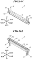
- the manifold 5 which is constituted by a molded resin member, is disposed on the pressure chambers 13A of the head chip 1 to store the ink that is to be introduced to the pressure chambers 13A. Specifically, as illustrated in FIG. 3B , FIG. 16A, FIG. 16B and the like, the manifold 5 is long in the right-left direction.
- the manifold 5 includes a hollow main body 52 that forms an ink reservoir 51 and first to fourth ink ports 53 to 56 that form ink flow paths.
- the main body 52 is formed in a cup shape that is open downward.
- a wiring board mount 521 is disposed on which the wiring board 2 is fixedly attached by bonding.
- the wiring board 2 with the head chip 1 is attached to the wiring board mount 521 so as to close the lower end opening.
- the ink reservoir 51 is thus formed.
- the first ink port 53 is communicated to the upper right end of the ink reservoir 51. Further, the second ink port 54 is communicated to the upper left end of the ink reservoir 51, and the third ink port 55 is communicated to the ink reservoir 51 at the further left and lower part relative to the part at which the second ink port 54 is communicated.
- a discharge room 57 is defined at a right lower end of the ink reservoir 51, which is communicated to the discharge flow paths 13B of the head chip 1.
- the fourth ink port 56 is communicated to the discharge room 57.
- a filter F for removing foreign matters in the ink is disposed inside the main body 52 at a slightly lower part from the center in the up-down direction of the ink reservoir 51.
- the ink reservoir 51 includes an inner side wall 511 that stands upward from the lower end of the main body 52 in the up-down direction and has approximately uniform height.
- the ink reservoir 51 extends a predetermined length inward from the upper end of the inner side wall 511 approximately in the front-back direction and the right-left direction so that a filter edge attaching part 512 is formed which is in contact with an outer edge of an approximately rectangular filter F.
- an end filter attaching part 513 is disposed across the front face and the rear face of the inner side wall 511, which is in contact with the part of the filter F that is slightly inside from the left end.
- the end filter attaching part 513 has approximately the same height as the filter edge attaching part 512.
- the filter F is fixedly attached to the end filter attaching part 513 and the filter edge attaching part 512 by bonding.
- the filter F disposed in the ink reservoir 51 partitions the ink reservoir 51 into a first room 51a that is communicated to the first ink port 53 and the second ink port 54, and a second room 51b that is communicated to the pressure chambers 13A of the head chip 1.
- the second room 51b is communicated with the third ink port 55 via the filter F.
- the first ink port 53 is provided, for example, to introduce ink to the ink reservoir 51.
- the first ink port 53 is formed in a cylindrical shape that extends in the up-down direction, and the outer diameter thereof is approximately uniform in the up-down direction.
- the first ink port 53 is inserted into a first insertion hole 66 (described below) of the case 6 when the manifold 5 is attached to the case 6.
- the outer diameter of the first ink port 53 is approximately equal to or slightly less than the inner diameter of the first insertion hole 66.
- a first joint 81a is fitted on the tip of the first ink port 53. That is, when the manifold 5 is attached to the case 6, the tip of the first ink port 53 is inserted into the first insertion hole 66 to protrude from the upper face of the case 6, and the first joint 81a is fitted on the protruded tip in a slidable manner in the up-down direction.
- the first joint 81a is constituted by a hose barb (joint member), and an ink supplying pipe (not shown) is connected to the upper end thereof.
- the first joint 81a is formed in a cylindrical shape that extends in the up-down direction.
- An ink pipe connector 811 is formed at the upper end, and a tip insert 812 is formed below the ink pipe connector 811. In the tip insert 812, the tip of the first ink port 53 is inserted.
- the second ink port 54 is provided, for example, to remove bubbles in the first room 51a.
- the second ink port 54 is formed in the approximately the same shape as the first ink port 53.
- the second ink port 54 is formed in a cylindrical shape that extends in the up-down direction, and the outer diameter thereof is approximately uniform in the up-down direction.
- the second ink port 54 is inserted into a second insertion hole 64 (described below) of the case 6 when the manifold 5 is attached to the case 6.
- the outer diameter of the second ink port 54 is approximately equal to or slightly less than the inner diameter of the second insertion hole 64.
- a second joint 81b is fitted on the tip of the second ink port 54. That is, when the manifold 5 is attached to the case 6, the tip of the second ink port 54 is inserted into the second insertion hole 64 to protrude from the upper face of the case 6, and the second joint 81b is fitted on the protruded tip in a slidable manner in the up-down direction.
- the second joint 81b includes a tip insert 812 at a lower part thereof, in which the tip of the second ink port 54 is inserted in a slidable manner in the up-down direction.
- the second joint 81b has approximately the same configuration as the first joint 81a that is fitted on the second ink port 54, and the detailed description thereof is omitted.
- the third ink port 55 is provided, for example, to remove bubbles in the second room 51b.
- the third ink port 55 is formed in a cylindrical shape that extends in the up-down direction, and the outer diameter thereof is approximately uninform in the up-down direction.
- the third ink port 55 is inserted into a third insertion hole 65 (described below) of the case 6 when the manifold 5 is attached to the case 6.
- the outer diameter of the third ink port 55 is approximately equal to or slightly less than the inner diameter of the third insertion hole 65.
- a third joint 82 is fitted (see FIG. 3A and the like). That is, when the manifold 5 is attached to the case 6, the tip of the third ink port 55 is inserted into the third insertion hole 65 to protrude from the upper face of the case 6, and the third joint 82 is fitted on the protruded tip in a slidable manner in the up-down direction.
- the third joint 82 is smaller than the first joint 81a or the second joint 81b so that it can be fitted on the tip of the third ink port 55.
- the third joint 82 has approximately the same configuration as the first joint 81a and the second joint 81b, and the detailed description thereof is omitted.
- the fourth ink port 56 is provided to discharge bubbles in the pressure chambers 13A in the head chip 1 out of the ink jet head 100 through the individual communication flow paths 18, the common communication flow paths 19 and the discharge flow paths 13B.
- the fourth ink port 56 is formed in a cylindrical shape that extends in the up-down direction, and the outer diameter thereof is approximately uniform in the up-down direction.
- the fourth ink port 56 is inserted into a discharge insertion hole 67 (described below) of the case 6 when the manifold 5 is attached to the case 6.
- the outer diameter of the fourth ink port 56 is approximately equal to or slightly less than the inner diameter of the discharge insertion hole 67.
- the case 6 is constituted by an aluminum member molded by a diecast method, which is long in the right-left direction.
- the case 6 is formed to be able to house the manifold 5 on which the head chip 1, the wiring board 2 and the flexible boards 3 are attached, and the bottom face of the case 6 is open.
- an approximately rectangular lower opening 61 that is long in the right-left direction is formed at the lower end of the case 6.
- the manifold 5 with the head chip 1, the wiring board 2 and the flexible boards 3 can be inserted into the case 6 from below through the lower opening 61 and placed therein.
- a cap receiver plate attaching part 62 is provided to which a cap receiver plate 7 (see FIG. 4 ) is fixedly attached.
- the cap receiver plate 7 has an approximately rectangular outer shape that is long in the right-left direction corresponding to the shape of the cap receiver plate attaching part 62 as illustrated in FIG. 4 . Approximately at a center thereof, a nozzle opening 71 that is long in the right-left direction is formed to expose the nozzle layer 11.
- the cap receiver plate 7 is attached to the cap receiver plate attaching part 62 such that the nozzle layer 11 is exposed through the nozzle opening 71.
- the lower opening 61 of the case 6 is thus closed.
- two board insert openings 63 are formed approximately at the center in the right-left direction of the case 6, in which the two driver circuit boards 4, 4 and the flexible boards 3, 3 connected to the manifold 5 are inserted.
- the board insert openings 63, 63 are closed when the cover member 9 (see FIG. 3A ) is attached to the case 6.
- the second insertion hole 64 is formed in which the tip of the second ink port 54 of the manifold 5 is inserted. Slightly to the left of the second insertion hole 64 and at a height lower than the second insertion hole 64, a third insertion hole 65 is formed in which the tip of the third ink port 55 of the manifold 5 is inserted (see FIG. 3B ).
- the second insertion hole 64 is formed in a left upper recess 641 that is recessed to a predetermined depth from a left first upper face 6a of the case 6.
- the second insertion hole 64 penetrates the bottom of the left upper recess 641 in the up-down direction.
- the size of the second insertion hole 64 is approximately equal to or slightly greater than the outer diameter of the second ink port 54.
- the outer edge of the second insertion hole 64 is approximately parallel to the right-left direction and the front-rear direction.
- the third insertion hole 65 is disposed in a left lower recess 651 that is recessed to a predetermined depth from a left second upper face 6b that is lower than the left first upper face 6a.
- the third insertion hole 65 penetrates the bottom face of the left lower recess 651 in the up-down direction.
- the size of the third insertion hole 65 is approximately equal to or slightly greater than the outer diameter of the third ink port 55.
- the outer edge of the third insertion hole 65 is approximately parallel to the right-left direction and the front-rear direction.
- the first insertion hole 66 is formed at approximately the same height as the second insertion hole 64, in which the tip of the first ink port 53 of the manifold 5 is inserted. Slightly to the right of the first insertion hole 66 and at a height lower than the first insertion hole 66, a discharge insertion hole 67 is formed in which the fourth ink port 56 of the manifold 5 is inserted (see FIG. 3B ).
- the first insertion hole 66 is disposed in a right upper recess 661 that is recessed to a predetermined depth from a right first upper face 6c of the case 6.
- the first insertion hole 66 penetrates the bottom face of the right upper recess 661 in the up-down direction.
- the size of the first insertion hole 66 is approximately equal to or slightly greater than the outer diameter of the first ink port 53. Further, the outer edge of the first insertion hole 66 is approximately parallel to the right-left direction and the front-rear direction.
- the discharge insertion hole 67 is disposed in a right lower recess 671 that is recessed to a predetermined depth from a right second upper face 6d that is lower than the right first upper face 6c.
- the discharge insertion hole 67 penetrates the bottom of the right lower recess 671 in the up-down direction.
- the size of the discharge insertion hole 67 is approximately equal to or slightly greater than the outer diameter of the fourth ink port 56.
- An outer edge of the discharge insertion hole 67 is approximately parallel to the right-left direction and the front-rear direction.
- attach holes 68 are respectively formed for attaching the case 6 to a printer main body.
- the ink jet recording apparatus 200 of the embodiment includes the ink circulating mechanism 8 as an ink circulator.
- the ink circulating mechanism 8 any suitable configuration may be selected that can generate a circulation flow from the pressure chamber 13A to the individual communication flow paths 18 to discharge the ink in the pressure chamber 13A out of the head chip through the discharge flow paths 13B.
- An example configuration will be described in the following.
- the ink circulating mechanism 8 includes a main tank 201, a sub tank 202, a circulation flow path 203 and the like ( FIG. 18).
- FIG. 18 is a conceptual view illustrating circulation of the ink in the ink jet recording apparatus 200, in which the arrows represent flow direction of the ink.
- the main tank 201 is filled with the ink that is to be supplied to the sub tank 202.
- the main tank 201 is connected to the sub tank 202 by an ink flow path.
- the ink can be supplied from the main tank 201 to the sub tank 202 by means of pressure that is applied by using a pump (not shown) as a pressure generator.
- the sub tank 202 is filled with ink that is to be supplied to the ink jet head 100.
- the sub tank 202 is connected to the first ink port 53 of the ink jet head 100 by an ink flow path.
- the ink can be supplied from the sub tank 202 to the ink jet head 100 by means of pressure that is applied by using a pump (not shown) as a pressure generator.
- the sub tank 202 has a gas-liquid separating function and can separate bubbles from the ink stored therein.
- the ink supplied from the sub tank 202 to the ink jet head 100 flows into the pressure chambers 13A through the first ink port 53 and the ink reservoir 51. That is, in the embodiment, the first ink port 53 and the ink reservoir 51 serve as a flow path for supplying the ink from the upstream of the pressure chambers 13A to the pressure chambers 13A.
- the partition wall between adjacent pressure chambers 13A is displaced so that the ink in the pressure chambers 13A is jetted through the nozzles 11a.
- the ink in the pressure chambers 13A also flows into the common communication flow paths 19 via the individual communication flow paths 18 along with bubbles and is thereafter discharged out of the ink jet head 100 through the discharge flow paths 13B, the discharge room 57 and the fourth ink port 56. That is, in the embodiment, the discharge flow paths 13B, the discharge room 57 and the fourth ink port 56 together serve as a flow path for discharging the ink from the common communication flow paths 19 out of the ink jet head 100.
- the fourth ink port 56 of the ink jet head 100 is connected to a circulation flow path 203 for supplying the ink discharged from the fourth ink port 56 to the sub tank 202.
- the ink discharged from the fourth ink port 56 is supplied to the sub tank 202 through the circulation flow path 203 and is thereafter separated from bubbles and reused.
- the head chip 1 of the ink jet head 100 of the present invention includes:
- the common communication flow path is disposed in the pressure chamber layer 12, it is possible to secure a large volume for the common communication flow path 19 for discharging ink so that bubbles and the like are effectively discharged. Furthermore, it is possible to reduce the size by disposing partition walls at regular intervals. By providing the common communication flow path 19 having a large volume, it is possible to increase the amount of ink circulated in the head chip 1 so that heat from the head chip 1 is effectively dissipated.
- the width in the up-down direction (the ink jetting direction) of the common communication flow path 19 of the head chip 1 is greater than the thickness of the nozzle layer 11. This allows the larger volume of the flow path compared to the case in which the common communication flow path 19 is disposed only in the nozzle layer 11.
- the individual communication flow paths 18 are disposed in the part facing the pressure chamber layer 12 of the nozzle layer 11. This allows forming the individual communication flow paths 18 at high precision by etching, etc. on a plate of the nozzle layer 11.
- the pressure chamber layer 12 includes the discharge flow paths 13B which are communicated with the common communication flow paths 19 and which are capable of discharging the ink upward (the opposite side from the nozzle layer 11). Since a discharge port of the ink is located in an upper part, it is possible to reduce the size of the ink jet head 100.
- the sealing member 12c is provided in the common communication flow paths 19 at an end in the longitudinal direction of the head chip 1 (right-left direction). This allows forming the common communication flow paths 19 in the head chip such that the common communication flow paths 19 penetrate the side walls in the longitudinal direction. Therefore, the ink jet head 100 can be produced by a method having high production efficiency.
- the width in the ink jetting direction (up-down direction) of the common communication flow paths 19 decreases toward the ends in the longitudinal direction (right-left direction) of the head chip 1 so that the upper face and the lower face come together to seal the common communication flow paths 19. This allows sealing the common communication flow paths only by joining the nozzle layer 11 to the pressure chamber layer 12.
- the manifold 5 is disposed above the pressure chambers 13A. Since the ink can be supplied and discharged only in the upper part, it is possible to further reduce the size of the ink jet head 100.
- the ink jet head 100 is suitably applicable to a share-mode ink jet head 100 with pressure chambers 13A partitioned from each other by a partition wall that causes share-mode displacement when a voltage is applied.
- the ink jet recording apparatus 200 includes the ink jet head 100 according to the embodiment and the ink circulator for generating a circulation flow from the pressure chambers 13A to the individual communication flow paths 18. With this configuration, the ink jet recording apparatus 200 can discharge bubbles near the pressure chambers 13A and the nozzles 11a out of the ink jet head 100 along with the ink.
- a share-mode ink jet head 100 is described as an example of the ink jet head 100.
- the ink jet head 100 is not limited to the share-mode type, and it is only necessary that a means for applying a pressure to the ink in the pressure chambers 13A is provided.
- a single-pass ink jet recording apparatus 200 with the line heads is described as the ink jet recording apparatus 200.
- the ink jet recording apparatus 200 may also be a scanning ink jet recording apparatus.
- the head chip 1 has two nozzle lines.
- the number of lines and the arrangement of the nozzles 11a may be suitably changed.
- the head chip 1 may have a single nozzle line, or three or more nozzle lines.
- the two discharge flow paths 13B are provided at the right part of the pressure chamber layer 12. However, only a single combined discharge flow path may be provided. Further, another discharge flow path 13B may be disposed at the left side in addition to the right side.
- the ink circulating mechanism 8 is described with FIG. 18 .
- the configuration may be suitably changed as long as the ink circulating mechanism 8 can generate a circulating flow from the pressure chambers 13A to the individual communication flow paths 18 to discharge the ink in the pressure chambers 13A out of the head chip through the discharge flow paths 13B.
- pairs of ink jet heads 100 each adjacent in the front-rear direction are arranged in a staggered pattern that staggers in the front-rear direction.
- the arrangement of the ink jet heads 100 may be suitably changed.
- FIG. 12 illustrates an example in which the common communication flow paths 19 get narrower toward the ends in the longitudinal direction so that the upper face and the lower face come together.
- the configuration is not limited to the example in FIG. 12 in which the upper face and the lower face are gradually come close to each other.
- the upper face may be formed in stepwise pattern.
- the pressure chambers 13A and the discharge flow paths 13B of the head chip 1 are straight that are open in the top and bottom faces of the head chip. Instead, while they are open in the bottom face of the head chip 1, they may be curved in the upper part and open in a side face of the head chip 1.
- the present invention is applicable to ink jet heads and ink jet recording apparatuses.
Landscapes
- Engineering & Computer Science (AREA)
- Manufacturing & Machinery (AREA)
- Ink Jet (AREA)
- Particle Formation And Scattering Control In Inkjet Printers (AREA)
Abstract
Description
- The present invention relates to an ink jet head and an ink jet recording apparatus.
- Ink jet recording apparatuses have been known in the art which form an image on a recording medium by jetting ink droplets from nozzles of an ink jet head. In ink jet recording apparatuses, single-pass printing of conveying a recording medium through a fixed ink jet head is known to have particularly high productivity. However, when there are bubbles and foreign matters near nozzles, a maintenance work is required to remove such bubbles and foreign matters. When the maintenance work takes a long time, the productivity is greatly deteriorated.
- To address the problem, some ink jet recording apparatuses known in the art have a flow path in a head chip of an ink jet head, which can circulate ink to remove bubbles and the like near the nozzles without any additional maintenance work.
- For example,
Patent Document 1 discloses an ink jet head that includes a pressure chamber for storing ink to be jetted from nozzles and a communication flow path (high impedance channel) connected to the vicinity of the nozzles. In the ink jet head, the ink flows toward the nozzles through the communication flow path so that bubbles and the like near the nozzles can be discharged to a manifold through the pressure chamber. -
Patent Document 2 discloses an ink jet head that includes pressure chambers that stores ink to be jetted through nozzles and that is defined by a partition wall of a piezoelectric material, individual communication flow paths connected to the vicinities of the nozzles, a common communication flow path that joins ink from the individual communication flow paths together, and a flow path for discharging the ink out of a head. In the ink jet head, the individual communication flow paths and a common communication flow path are disposed on a base board on which the nozzles are mounted, and bubbles and the like near the nozzles can be discharged out of the ink jet head through the flow paths along with the ink. - The ink jet heads of
Patent Document 1 andPatent Document 2 can remove bubbles and the like near the nozzles while jetting ink from the nozzles. This can prevent deterioration of the productivity caused by an additional maintenance work. -
- Patent Document 1:
JP 5047958B - Patent Document 2:
JP 5381915B - However, the ink jet head of
Patent Document 1 requires providing the communication flow path (high impedance channel) and the pressure chamber having relatively large volume in a head chip. Accordingly, a problem is the increased size when the ink jet head includes a number of nozzles. Particularly in an ink jet recording apparatus (seeFIG. 1 ) that performs continuous printing on recording media with a rotating drum and a fixed ink jet head, it is difficult to keep a constant distance between a recording medium and nozzles of the ink jet head and to perform high definition printing when the size of the ink jet head is large. Therefore, there is a need for reducing the size of the ink jet head. It is desirable to reduce the size of the ink jet head also in terms of the increased production cost due to increased materials for production and a reduction in size of the apparatus. - The ink jet head of
Patent Document 2 can be reduced in size since the flow paths are disposed on the base board of the nozzles. However, since the individual communication flow paths and the common communication flow path are formed only in a narrow area in the base board of the nozzles, it is difficult to reduce the flow resistance of the flow paths. Therefore, it is therefore difficult to generate circulation flow of ink that is sufficient to discharge bubbles and the like. - The present invention has been made in view of these problems, and an object thereof is to provide an ink jet head and an ink jet recording apparatus that can be reduced in size and that have a flow path capable of effectively discharging bubbles and the like.
- In order to solve the above problem, the invention according to
claim 1 is an ink jet head, including: - a head chip which comprises a nozzle layer with nozzles for jetting ink and a pressure chamber layer with pressure chambers communicated respectively with the nozzles; and
- a manifold which stores the ink to be supplied to the pressure chambers;
- wherein the head chip includes:
- individual communication flow paths which are communicated respectively with the pressure chambers and which are capable of discharging the ink in the pressure chambers; and
- a common communication flow path which is disposed in a part facing the nozzle layer of the pressure chamber layer and which is connected to the individual communication flow paths to join the ink discharged from the individual communication flow paths together.
- The invention according to
claim 2 is the ink jet head according toclaim 1, wherein a width in an ink jetting direction of the common communication flow path is greater than a thickness of the nozzle layer. - The invention according to
claim 3 is the ink jet head according toclaim - The invention according to
claim 4 is the ink jet head according to any one ofclaims 1 to 3, wherein the pressure chamber layer comprises a discharge flow path which is communicated with the common communication flow path and which is capable of discharging the ink toward an opposite side from the nozzle layer. - The invention according to
claim 5 is the ink jet head according to any one ofclaims 1 to 4, wherein a sealing member is provided in the common communication flow path at an end in a longitudinal direction of the head chip. - The invention according to
claim 6 is the ink jet head according to any one ofclaims 1 to 4, wherein a width in an ink jetting direction of the common communication flow path decreases toward an end in the longitudinal direction of the head chip so that an upper face and a lower face come together to seal the common communication flow path. - The invention according to
claim 7 is the ink jet head according to any one ofclaims 1 to 6, wherein the manifold is disposed above the pressure chambers. - The invention according to
claim 8 is the ink jet head according to any one ofclaims 1 to 7, wherein the pressure chambers are partitioned from each other by a partition wall that causes share-mode displacement when a voltage is applied. - The invention according to
claim 9 is an ink jet recording apparatus, including: - the ink jet head according to any one of
claims 1 to 8; - an ink circulator for generating a circulation flow from the pressure chambers to the individual communication flow paths.
- With the present invention, it is possible to provide an ink jet head and an ink jet recording apparatus that can be reduced in size and that has a flow path capable of effectively discharging bubbles and the like.
-
-
FIG. 1 is a schematic view of an ink jet recording apparatus. -
FIG. 2 is a bottom view of a head unit. -
FIG. 3A is a perspective view of an ink jet head. -
FIG. 3B is a cross-sectional view of the ink jet head. -
FIG. 4 is an exploded perspective view of the ink jet head. -
FIG. 5A is a perspective view from above of a head chip, a wiring board, flexible boards and driver circuit boards. -
FIG. 5B is a perspective view from below of the head chip, the wiring board, the flexible boards and the driver circuit board. -
FIG. 6 is a schematic exploded perspective view of the head chip and the wiring board. -
FIG. 7 is a perspective view from below illustrating ink flow in the head chip. -
FIG. 8 is a cross-sectional view taken along the line VIII-VIII inFIG. 7 . -
FIG. 9 is a cross-sectional view of a variation ofFIG. 8 . -
FIG. 10 is a cross-sectional view taken along the line X-X inFIG. 7 . -
FIG. 11 is a cross-sectional view taken along the line XI-XI inFIG. 7 . -
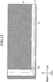
FIG. 12 is a cross-sectional view of a variation ofFIG. 11 . -
FIG. 13 is a perspective view of a nozzle layer of the head chip. -
FIG. 14 is an enlarged plan view of the part around the upstream end of an individual communication flow path on an upper surface of the nozzle layer, which is the part XIV indicated by the dashed line inFIG. 13 . -
FIG. 15 is a plan view of a variation ofFIG. 14 . -
FIG. 16A is a perspective view from above of a manifold. -
FIG. 16B is a perspective view from below of the manifold. -
FIG. 17A is a perspective view from above of a case. -
FIG. 17B is a perspective view form below of the case. -
FIG. 18 is a conceptual view illustrating an ink circulating mechanism of the ink jet recording apparatus. - Hereinafter, a preferred embodiment of the present invention will be described referring to the drawings. However, the scope of the invention is not limited to the illustrated examples. As used herein, the array direction of
nozzles 11a of anink jet head 100 is referred to as the right-left direction (seeFIG. 2 ,FIG. 6 andFIG. 7 ), the ink jetting direction is referred to as the up-down direction, and the direction perpendicular to both right-left direction and up-down direction is referred to as the front-rear direction. Further, the arrows in the flow paths in the drawings represent the flow direction of ink. - As illustrated in
FIG. 1 , an inkjet recording apparatus 200 includes asheet feeder 210, animage recorder 220, asheet ejector 230 and an ink circulating mechanism 8 (seeFIG. 18 ) and the like. The inkjet recording apparatus 200 conveys a recording medium M stored in thesheet feeder 210 to theimage recorder 220, forms an image on the recording medium M with theimage recorder 220 and conveys the recording medium M with the image formed thereon to thesheet ejector 230. - Recording media M that can be used include a variety of media which can fix ink landed on the surface, such as fabric and sheet resin as well as paper such as normal paper and coated paper.
- The
sheet feeder 210 includes asheet feeding tray 211 for storing the recording medium M and amedium feeder 212 that conveys and feeds the recording medium M from thesheet feeding tray 211 to theimage recorder 220. Themedium feeder 212, which includes a ring belt supported from inside by two rollers, conveys the recording medium M from thesheet feeding tray 211 to theimage recorder 220 by rotating the rollers when the recording medium M is mounted on the belt. - The
image recorder 220 includes aconveyance drum 221, ahandover unit 222, aheater 223,head units 224, afixer 225, adeliverer 226 and the like. - The
conveyance drum 221 has a cylindrical surface, and the outer peripheral surface serves as a conveyance surface on which the recording medium M is mounted. Theconveyance drum 221 conveys the recording medium M along the conveyance surface by rotating in the arrow direction inFIG. 1 when the recording medium M is held on the conveyance surface. Theconveyance drum 221 includes hooks and suctioning parts (not shown). The hooks fix an end of the recording medium M, and the suctioning parts suction the recording medium M on the conveyance surface, so that the recording medium M is held on the conveyance surface. - The
handover unit 222, which is disposed between themedium feeder 212 of thesheet feeder 210 and theconveyance drum 221, catches and picks up an end of the recording medium M conveyed from themedium feeder 212 with aswing arm 222a and hands it over to theconveyance drum 221 via the handover drum 222b. - The
heater 223, which is disposed between the position of the handover drum 222b and the position of thehead units 224, heats the recording medium M conveyed from theconveyance drum 221 so that the temperature of the recording medium M falls within a predetermined temperature range. Theheater 223, which includes, for example, an infrared heater and the like, applies electricity to the infrared heater according to a control signal supplied from the hardware processor (not shown) to generate heat. - The
head units 224 jet ink to the recording medium M based on image data at a suitable timing in synchronization with the rotation of theconveyance drum 221 on which the recording medium M is held, so as to form an image. Thehead units 224 is disposed such that ink jetting surfaces are opposed to theconveyance drum 221 at a predetermined distance. In the inkjet recording apparatus 200 of the embodiment, for example, fourhead units 224 corresponding respectively to the four colors of yellow (Y), magenta (M), cyan (C) and black (K) are aligned at predetermined intervals in the order of Y, M, C and K from the upstream of the conveyance direction of the recording medium M. - In the
head units 224, pairs of ink jet heads 100, each mutually adjacent in the front-rear direction, are arranged in a staggered pattern that staggers in the front-rear direction as illustrated in the bottom view inFIG. 2 . In this arrangement of the ink jet heads 100, the array width in the right-left direction of thenozzles 11a of the ink jet heads 100 is equal to or greater than the width of an image forming area of the recording medium M. Thehead units 224 are fixed relative to the rotation axis of theconveyance drum 221 when an image is being recorded. That is, the inkjet recording apparatus 200 records an image by single-pass printing with the line heads. - For example, the ink to be jetted from the
nozzles 11a of the ink jet heads 100 has the characteristics of causing phase transition between gel and sol depending on temperature and curing by energy ray such as ultraviolet ray. - For example, the ink that is used in the embodiment is in gel state at ordinary temperature but turns into solution when heated. The
head units 224 include ink heaters (not shown) for heating the ink stored in thehead units 224. The ink heaters can heat the ink to a temperature at which the ink is in solution state. The ink jet heads 100 jet the heated solution ink. When the solution ink is jetted to the recording medium M, ink droplets that are landed on the recording medium M are naturally cooled to rapidly turn into gel. The ink is thus solidified on the recording medium M. - The
fixer 225, which includes a light emitter disposed over theconveyance drum 221 in the X direction, emits an energy ray such as ultraviolet ray from the light emitter to the recording medium M mounted on theconveyance drum 221 so as to cure and fix the ink jetted on the recording medium M. The light emitter of thefixer 225 is disposed opposite to the conveyance surface in the downstream of the position of thehead units 224 and the upstream of the position of ahandover drum 226a of thedeliverer 226 with respect to the conveyance direction. - The
deliverer 226 includes abelt loop 226b with a ring belt supported from inside by two rollers, and thecylindrical handover drum 226a that hands over the recording medium M from theconveyance drum 221 to thebelt loop 226b. Thebelt loop 226b conveys the recording medium M toward thesheet ejector 230, which has been handed over from theconveyance drum 221 onto thebelt loop 226b by thehandover drum 226a. - The
sheet ejector 230 includes asheet ejecting tray 231 having a plate shape on which the recording medium P sent from theimage recorder 220 by thedeliverer 226 is placed. -
FIG. 3A is a perspective view of anink jet head 100 of the embodiment in which the present invention is implemented, andFIG. 3B is a cross-sectional view of theink jet head 100.FIG. 4 is an exploded perspective view of theink jet head 100. Amanifold 5 is not shown inFIG. 3A , and acover member 9 is not shown inFIG. 3B andFIG. 4 . - This embodiment is an example in which the
head chip 1 has two nozzle lines. However, the number of lines and the arrangement of thenozzles 11a can be suitably changed. For example, thehead chip 1 may also have a single line, or three or more lines. - As illustrated in
FIG. 3A, FIG. 3B andFIG. 4 , each of the ink jet heads 100 of the embodiment includes thehead chip 1, awiring board 2 on which thehead chip 1 is disposed,driver circuit boards 4 connected via thewiring board 2 andflexible boards 3, themanifold 5 that stores the ink to be supplied topressure chambers 13A in thehead chip 1, acase 6 in which themanifold 5 is housed, acap receiver plate 7 that is attached to close a bottom opening of thecase 6, thecover member 9 that is attached to thecase 6, and the like. - The
head chip 1 has an approximately square pillar shape that is long in the right-left direction. Thehead chip 1 is composed of anozzle layer 11 and a pressure chamber layer 12 (seeFIG. 6 andFIG. 7 ).FIG. 7 to FIG. 13 schematically illustrate an enlargement of a part of thehead chip 1, but the portion at the left end of thehead chip 1 is not shown in the figures. - The
pressure chamber layer 12 includes thepressure chambers 13A,discharge flow paths 13B and commoncommunication flow paths 19. - The
pressure chambers 13A, which are separated from each other by partition walls of a piezoelectric material, store the ink to be jetted from thenozzles 11a. In an inner wall of each of thepressure chambers 13A, adriver electrode 14 is provided to move a partition wall betweenadjacent pressure chambers 13A. When a voltage is applied to thedriver electrode 14, the partition wall between theadjacent pressure chambers 13A repeats share-mode displacement to apply a pressure on the ink in thepressure chamber 13A. In the embodiment, thedriver electrode 14 is constituted by a metal film. - Each of the
pressure chambers 13A, which has an approximately rectangular cross section, extends in the up-down direction and has an inlet in the top surface of thepressure chamber layer 12 and an out let in the bottom surface. Each of thepressure chambers 13A is a straight-type chamber that has approximately uniform size and the shape in the longitudinal direction (up-down direction) from the inlet to the outlet. Thepressure chambers 13A are disposed parallel to each other. Thepressure chambers 13A are arrayed in the right-left direction such that they form two lines adjacent in the front-rear direction. In the figures other thanFIG. 6 , thedriver electrodes 14 are not shown. - The
discharge flow paths 13B, which are defined by partition walls as with thepressure chambers 13A, are provided to discharge the ink upward (to the opposite side from the nozzle layer 11) out of the ink jet heads 100. Thedischarge flow paths 13B extends in the up-down direction and has outlets in the top surface of thepressure chamber layer 12 and inlets in the bottom surface. Thedischarge flow paths 13B are straight-type paths that have approximately the same size and the shape in the longitudinal direction (up-down direction) from the inlets to the outlets. Twodischarge flow paths 13B are disposed near the right end of thehead chip 1 parallel to thepressure chambers 13A. - It is preferred that the
discharge flow paths 13B have a volume that is greater than the volume of thepressure chambers 13A as illustrated inFIG. 6 ,FIG. 10 andFIG. 11 in order to improve the efficiency of discharging the ink. - The common
communication flow paths 19 are disposed in the part facing thenozzle layer 11 of thepressure chamber layer 12. The commoncommunication flow paths 19 are connected to individualcommunication flow paths 18 which are further connected to thepressure chambers 13A, so that the ink flowing through the individualcommunication flow paths 18 joins together. The commoncommunication flow paths 19 are disposed in the right-left direction for the respective nozzle lines, which are communicated with thedischarge flow paths 13B near the right ends of the common flow paths (seeFIG. 6 ,FIG. 7 andFIG. 11 ). In the embodiment, since the commoncommunication flow paths 19 are disposed in thepressure chamber layer 12, the width in the up-down direction of the commoncommunication flow paths 19 can be greater than the thickness of thenozzle layer 11. This allows increasing the volume of the flow paths compared to a case in which the common communication flow paths are disposed only in thenozzle layer 11. Further, the commoncommunication flow paths 19 with a large volume can increase the amount of ink circulated in thehead chip 1. This allows efficient discharge of bubbles and the like. Further, this allows efficient heat dissipation from thehead chip 1. - The
nozzle layer 11 is constituted by a rectangular plate member, which is disposed on the bottom surface of thepressure chamber layer 12 to close lower ends of thepressure chambers 13A and thedischarge flow paths 13B. Thenozzle layer 11 includes thenozzles 11a and the individualcommunication flow paths 18 and the like. - The
nozzles 11a, which are disposed opposite to therespective pressure chambers 13A, penetrate thenozzle layer 11 in the thickness direction (up-down direction) so as to jet the ink stored in the communicatedpressure chambers 13A. In the embodiment, thenozzles 11a are arrayed in the right-left direction. Further, thenozzles 11a form two lines adjacent in the front-rear direction. - The individual
communication flow paths 18 are disposed in the part facing thepressure chamber layer 12 of thenozzle layer 11, which extend in the front-rear direction from thenozzles 11a to the commoncommunication flow paths 19 so as to communicate thepressure chambers 13A with the common communication flow paths 19 (seeFIG. 8 ,FIG. 13 and the like). - In the embodiment, one common
communication flow path 19 is provided with respect to each of the nozzle lines, and the individualcommunication flow paths 18 are disposed only from eachnozzle 11a to a proximate common communication flow path 19 (FIG. 8 andFIG. 13 ). However, the configuration is not limited thereto. For example, in a variation as illustrated inFIG. 9 , parallel commoncommunication flow paths 19 that are adjacent in the front-rear direction may be provided at both sides in the front-rear direction of thepressure chambers 13A, and individualcommunication flow paths communication flow paths - In the embodiment, the individual
communication flow paths 18 are formed only in thenozzle layer 11. However, it is not necessary to form them exclusively in thenozzle layer 11 as long as they can communicate thepressure chambers 13A with the commoncommunication flow paths 19. The individualcommunication flow paths 18 may also be formed in thepressure chamber layer 12 or across thenozzle layer 11 and thepressure chamber layer 12. - When the individual
communication flow paths 18 are disposed in thenozzle layer 11, it is preferred to form the commoncommunication flow paths 19 across thenozzle layer 11 as illustrated inFIG. 13 . This can facilitate the flow of the ink from the individualcommunication flow paths 18 to the commoncommunication flow paths 19 in thepressure chamber layer 12. -
FIG. 11 illustrates a cross section of thehead chip 1 taken in the up-down direction through a common communication flow path 19 (taken along the line XI-XI inFIG. 7 ). A sealingmember 12c is disposed at an end in the longitudinal direction (right-left direction) of the commoncommunication flow path 19 to close the end. This configuration allows producing the commoncommunication flow paths 19 in thepressure chamber layer 12 such that the commoncommunication flow paths 19 penetrate in the right-left direction (longitudinal direction of the common communication flow paths 19) through the side walls. That is, the commoncommunication flow paths 19 can be produced by a method having high production efficiency. - The configuration for sealing the common
communication flow paths 19 may be changed to any suitable configuration that can seal the commoncommunication flow paths 19 and prevent a leakage of the ink. For example, the width in the up-down direction (ink jetting direction) may be narrowed toward the side walls in the right-left direction of thehead chip 1 so that the upper face and the lower face come together to seal the common communication flow paths 19 (FIG. 12 ). This configuration allows sealing the commoncommunication flow paths 19 only by joining thenozzle layer 11 to thepressure chamber layer 12. - While the left end portion is not shown in
FIG. 11 andFIG. 12 , it is preferred that the side wall of the commoncommunication flow paths 19 are sealed similarly as in the right end portion. -
FIG. 14 is an enlarged plan view of the part (indicated by the dashed line XIV inFIG. 13 ) around the upstream end of an individualcommunication flow path 18 in the upper surface of thenozzle layer 11. As illustrated inFIG. 8 andFIG. 14 ,rectangular recesses 11b are formed at upper parts of thenozzles 11a in thenozzle layer 11, and thenozzles 11a are pierced in therecesses 11b. - As illustrated in
FIG. 14 , upstream ends of the individualcommunication flow paths 18 are formed in a tapered shape so that the width becomes greater toward therecesses 11b (upstream). This shape is less likely to trap bubbles and makes it easier to discharge bubbles around thenozzles 11a. -
FIG. 15 is an enlarged plan view of the part around the upstream end of an individualcommunication flow path 18 of thehead chip 1 according to the variation as illustrated inFIG. 9 . In the variation, the individualcommunication flow paths recesses 11b in thenozzle layer 11 toward the corresponding commoncommunication flow paths recesses 11b. - For example, the
nozzle layer 11 as described above can be produced by forming thenozzles 11a, therecesses 11b and the commoncommunication flow paths 18 at once on a polyimide plate by laser machining or on a silicon plate by etching. The material of thenozzle layer 11 may be resin or metal that can be formed by etching. - On the upper face of the
head chip 1, thewiring board 2 is disposed as illustrated inFIG. 5A and FIG. 5B . The twoflexible board driver circuit boards wiring board 2. - The
wiring board 2 is formed in an approximately rectangular shape that is long in the right-left direction and has anopening 22 approximately at the center. The width of thewiring board 2 is greater than that of thehead chip 1 in both right-left direction and front-rear direction. - The
opening 22 is formed in an approximately rectangular shape that is long in the right-left direction so that when thehead chip 1 is attached to thewiring board 2, the inlets of thepressure chambers 13A and the outlets of thedischarge flow paths 13B of thehead chip 1 are exposed upward. - At the edges in the front-rear direction of the
opening 22, a predetermined number ofelectrode parts 21 are disposed, which are connected to electrodes (not shown) on the upper face of thehead chip 1 extended from thedriver electrodes 14 of the head chip 1 (FIG. 6 ). - As illustrated in
FIG. 4 ,FIG. 5A, FIG. 5B and the like, theflexible boards 3 are disposed at the ends in the front-rear direction of thewiring board 2. - As illustrated in
FIG. 6 , theflexible board 3 includeswirings 31, ... that electrically connect thedriver circuit boards 4 to theelectrode parts 21 of thewiring board 2. Accordingly, signals from thedriver circuit boards 4 are applied to thedriver electrodes 14 in thepressure chambers 13A of thehead chip 1 via thewirings 31 and theelectrode parts 21. - As illustrated in
FIG. 4 , a lower end of themanifold 5 is fixedly attached to an outer edge of thewiring board 2 by bonding. That is, themanifold 5 is disposed at the inlets (upper side) of thepressure chambers 13A of thehead chip 1 and coupled thehead chip 1 via thewiring board 2. - The
manifold 5, which is constituted by a molded resin member, is disposed on thepressure chambers 13A of thehead chip 1 to store the ink that is to be introduced to thepressure chambers 13A. Specifically, as illustrated inFIG. 3B ,FIG. 16A, FIG. 16B and the like, themanifold 5 is long in the right-left direction. Themanifold 5 includes a hollowmain body 52 that forms anink reservoir 51 and first tofourth ink ports 53 to 56 that form ink flow paths. - The
main body 52 is formed in a cup shape that is open downward. At the edge of the lower end opening, awiring board mount 521 is disposed on which thewiring board 2 is fixedly attached by bonding. Thewiring board 2 with thehead chip 1 is attached to thewiring board mount 521 so as to close the lower end opening. Theink reservoir 51 is thus formed. - The
first ink port 53 is communicated to the upper right end of theink reservoir 51. Further, thesecond ink port 54 is communicated to the upper left end of theink reservoir 51, and thethird ink port 55 is communicated to theink reservoir 51 at the further left and lower part relative to the part at which thesecond ink port 54 is communicated. Adischarge room 57 is defined at a right lower end of theink reservoir 51, which is communicated to thedischarge flow paths 13B of thehead chip 1. Thefourth ink port 56 is communicated to thedischarge room 57. - As illustrated in
FIG. 3B , a filter F for removing foreign matters in the ink is disposed inside themain body 52 at a slightly lower part from the center in the up-down direction of theink reservoir 51. - As illustrated in
FIG. 3B andFIG. 8B , theink reservoir 51 includes aninner side wall 511 that stands upward from the lower end of themain body 52 in the up-down direction and has approximately uniform height. Theink reservoir 51 extends a predetermined length inward from the upper end of theinner side wall 511 approximately in the front-back direction and the right-left direction so that a filteredge attaching part 512 is formed which is in contact with an outer edge of an approximately rectangular filter F. - At the left end of the filter
edge attaching part 512 and between thesecond ink port 54 and thethird ink port 55, an endfilter attaching part 513 is disposed across the front face and the rear face of theinner side wall 511, which is in contact with the part of the filter F that is slightly inside from the left end. The endfilter attaching part 513 has approximately the same height as the filteredge attaching part 512. - The filter F is fixedly attached to the end
filter attaching part 513 and the filteredge attaching part 512 by bonding. - The filter F disposed in the
ink reservoir 51 partitions theink reservoir 51 into afirst room 51a that is communicated to thefirst ink port 53 and thesecond ink port 54, and a second room 51b that is communicated to thepressure chambers 13A of thehead chip 1. The second room 51b is communicated with thethird ink port 55 via the filter F. - The
first ink port 53 is provided, for example, to introduce ink to theink reservoir 51. Thefirst ink port 53 is formed in a cylindrical shape that extends in the up-down direction, and the outer diameter thereof is approximately uniform in the up-down direction. Thefirst ink port 53 is inserted into a first insertion hole 66 (described below) of thecase 6 when themanifold 5 is attached to thecase 6. The outer diameter of thefirst ink port 53 is approximately equal to or slightly less than the inner diameter of thefirst insertion hole 66. - On the tip of the
first ink port 53, a first joint 81a is fitted. That is, when themanifold 5 is attached to thecase 6, the tip of thefirst ink port 53 is inserted into thefirst insertion hole 66 to protrude from the upper face of thecase 6, and the first joint 81a is fitted on the protruded tip in a slidable manner in the up-down direction. The first joint 81a is constituted by a hose barb (joint member), and an ink supplying pipe (not shown) is connected to the upper end thereof. Specifically, the first joint 81a is formed in a cylindrical shape that extends in the up-down direction. Anink pipe connector 811 is formed at the upper end, and atip insert 812 is formed below theink pipe connector 811. In thetip insert 812, the tip of thefirst ink port 53 is inserted. - The
second ink port 54 is provided, for example, to remove bubbles in thefirst room 51a. Thesecond ink port 54 is formed in the approximately the same shape as thefirst ink port 53. - That is, the
second ink port 54 is formed in a cylindrical shape that extends in the up-down direction, and the outer diameter thereof is approximately uniform in the up-down direction. Thesecond ink port 54 is inserted into a second insertion hole 64 (described below) of thecase 6 when themanifold 5 is attached to thecase 6. The outer diameter of thesecond ink port 54 is approximately equal to or slightly less than the inner diameter of thesecond insertion hole 64. - On the tip of the
second ink port 54, a second joint 81b is fitted. That is, when themanifold 5 is attached to thecase 6, the tip of thesecond ink port 54 is inserted into thesecond insertion hole 64 to protrude from the upper face of thecase 6, and the second joint 81b is fitted on the protruded tip in a slidable manner in the up-down direction. The second joint 81b includes atip insert 812 at a lower part thereof, in which the tip of thesecond ink port 54 is inserted in a slidable manner in the up-down direction. The second joint 81b has approximately the same configuration as the first joint 81a that is fitted on thesecond ink port 54, and the detailed description thereof is omitted. - The
third ink port 55 is provided, for example, to remove bubbles in the second room 51b. Thethird ink port 55 is formed in a cylindrical shape that extends in the up-down direction, and the outer diameter thereof is approximately uninform in the up-down direction. Thethird ink port 55 is inserted into a third insertion hole 65 (described below) of thecase 6 when themanifold 5 is attached to thecase 6. The outer diameter of thethird ink port 55 is approximately equal to or slightly less than the inner diameter of thethird insertion hole 65. - On the tip of the
third ink port 55, a third joint 82 is fitted (seeFIG. 3A and the like). That is, when themanifold 5 is attached to thecase 6, the tip of thethird ink port 55 is inserted into thethird insertion hole 65 to protrude from the upper face of thecase 6, and the third joint 82 is fitted on the protruded tip in a slidable manner in the up-down direction. The third joint 82 is smaller than the first joint 81a or the second joint 81b so that it can be fitted on the tip of thethird ink port 55. The third joint 82 has approximately the same configuration as the first joint 81a and the second joint 81b, and the detailed description thereof is omitted. - The
fourth ink port 56 is provided to discharge bubbles in thepressure chambers 13A in thehead chip 1 out of theink jet head 100 through the individualcommunication flow paths 18, the commoncommunication flow paths 19 and thedischarge flow paths 13B. Thefourth ink port 56 is formed in a cylindrical shape that extends in the up-down direction, and the outer diameter thereof is approximately uniform in the up-down direction. Thefourth ink port 56 is inserted into a discharge insertion hole 67 (described below) of thecase 6 when themanifold 5 is attached to thecase 6. The outer diameter of thefourth ink port 56 is approximately equal to or slightly less than the inner diameter of thedischarge insertion hole 67. - Next, the
case 6 will be described referring toFIG. 17A and FIG. 17B . - The
case 6 is constituted by an aluminum member molded by a diecast method, which is long in the right-left direction. Thecase 6 is formed to be able to house themanifold 5 on which thehead chip 1, thewiring board 2 and theflexible boards 3 are attached, and the bottom face of thecase 6 is open. - Specifically, an approximately rectangular
lower opening 61 that is long in the right-left direction is formed at the lower end of thecase 6. Themanifold 5 with thehead chip 1, thewiring board 2 and theflexible boards 3 can be inserted into thecase 6 from below through thelower opening 61 and placed therein. - At the edge of the
lower opening 61, a cap receiverplate attaching part 62 is provided to which a cap receiver plate 7 (seeFIG. 4 ) is fixedly attached. - The
cap receiver plate 7 has an approximately rectangular outer shape that is long in the right-left direction corresponding to the shape of the cap receiverplate attaching part 62 as illustrated inFIG. 4 . Approximately at a center thereof, anozzle opening 71 that is long in the right-left direction is formed to expose thenozzle layer 11. - After the
manifold 5 with thehead chip 1, thewiring board 2 and theflexible boards 3 is disposed in thecase 6, thecap receiver plate 7 is attached to the cap receiverplate attaching part 62 such that thenozzle layer 11 is exposed through thenozzle opening 71. Thelower opening 61 of thecase 6 is thus closed. - As illustrated in
FIG. 4 ,FIG. 17A, FIG. 17B and the like, twoboard insert openings 63 are formed approximately at the center in the right-left direction of thecase 6, in which the twodriver circuit boards flexible boards manifold 5 are inserted. - The
board insert openings FIG. 3A ) is attached to thecase 6. - To the left of the two
board insert openings case 6, thesecond insertion hole 64 is formed in which the tip of thesecond ink port 54 of themanifold 5 is inserted. Slightly to the left of thesecond insertion hole 64 and at a height lower than thesecond insertion hole 64, athird insertion hole 65 is formed in which the tip of thethird ink port 55 of themanifold 5 is inserted (seeFIG. 3B ). - The
second insertion hole 64 is formed in a leftupper recess 641 that is recessed to a predetermined depth from a left firstupper face 6a of thecase 6. Thesecond insertion hole 64 penetrates the bottom of the leftupper recess 641 in the up-down direction. The size of thesecond insertion hole 64 is approximately equal to or slightly greater than the outer diameter of thesecond ink port 54. The outer edge of thesecond insertion hole 64 is approximately parallel to the right-left direction and the front-rear direction. - The
third insertion hole 65 is disposed in a leftlower recess 651 that is recessed to a predetermined depth from a left secondupper face 6b that is lower than the left firstupper face 6a. Thethird insertion hole 65 penetrates the bottom face of the leftlower recess 651 in the up-down direction. The size of thethird insertion hole 65 is approximately equal to or slightly greater than the outer diameter of thethird ink port 55. The outer edge of thethird insertion hole 65 is approximately parallel to the right-left direction and the front-rear direction. - To the right of the two
board insert openings case 6, thefirst insertion hole 66 is formed at approximately the same height as thesecond insertion hole 64, in which the tip of thefirst ink port 53 of themanifold 5 is inserted. Slightly to the right of thefirst insertion hole 66 and at a height lower than thefirst insertion hole 66, adischarge insertion hole 67 is formed in which thefourth ink port 56 of themanifold 5 is inserted (seeFIG. 3B ). - The
first insertion hole 66 is disposed in a rightupper recess 661 that is recessed to a predetermined depth from a right firstupper face 6c of thecase 6. Thefirst insertion hole 66 penetrates the bottom face of the rightupper recess 661 in the up-down direction. The size of thefirst insertion hole 66 is approximately equal to or slightly greater than the outer diameter of thefirst ink port 53. Further, the outer edge of thefirst insertion hole 66 is approximately parallel to the right-left direction and the front-rear direction. - The
discharge insertion hole 67 is disposed in a rightlower recess 671 that is recessed to a predetermined depth from a right secondupper face 6d that is lower than the right firstupper face 6c. Thedischarge insertion hole 67 penetrates the bottom of the rightlower recess 671 in the up-down direction. The size of thedischarge insertion hole 67 is approximately equal to or slightly greater than the outer diameter of thefourth ink port 56. An outer edge of thedischarge insertion hole 67 is approximately parallel to the right-left direction and the front-rear direction. - At an end and to the left of the
third insertion hole 65 of thecase 6 and at an end and to the right of thedischarge insertion hole 67, attachholes 68 are respectively formed for attaching thecase 6 to a printer main body. - The ink
jet recording apparatus 200 of the embodiment includes theink circulating mechanism 8 as an ink circulator. For theink circulating mechanism 8, any suitable configuration may be selected that can generate a circulation flow from thepressure chamber 13A to the individualcommunication flow paths 18 to discharge the ink in thepressure chamber 13A out of the head chip through thedischarge flow paths 13B. An example configuration will be described in the following. - The
ink circulating mechanism 8 includes amain tank 201, asub tank 202, acirculation flow path 203 and the like (FIG. 18). FIG. 18 is a conceptual view illustrating circulation of the ink in the inkjet recording apparatus 200, in which the arrows represent flow direction of the ink. - The
main tank 201 is filled with the ink that is to be supplied to thesub tank 202. Themain tank 201 is connected to thesub tank 202 by an ink flow path. For example, the ink can be supplied from themain tank 201 to thesub tank 202 by means of pressure that is applied by using a pump (not shown) as a pressure generator. - The
sub tank 202 is filled with ink that is to be supplied to theink jet head 100. Thesub tank 202 is connected to thefirst ink port 53 of theink jet head 100 by an ink flow path. For example, the ink can be supplied from thesub tank 202 to theink jet head 100 by means of pressure that is applied by using a pump (not shown) as a pressure generator. Thesub tank 202 has a gas-liquid separating function and can separate bubbles from the ink stored therein. - The ink supplied from the
sub tank 202 to theink jet head 100 flows into thepressure chambers 13A through thefirst ink port 53 and theink reservoir 51. That is, in the embodiment, thefirst ink port 53 and theink reservoir 51 serve as a flow path for supplying the ink from the upstream of thepressure chambers 13A to thepressure chambers 13A. As described above, when a voltage is applied to thedriver electrodes 14 of thepressure chambers 13A, the partition wall betweenadjacent pressure chambers 13A is displaced so that the ink in thepressure chambers 13A is jetted through thenozzles 11a. - While being jetted through the
nozzles 11a as described above, the ink in thepressure chambers 13A also flows into the commoncommunication flow paths 19 via the individualcommunication flow paths 18 along with bubbles and is thereafter discharged out of theink jet head 100 through thedischarge flow paths 13B, thedischarge room 57 and thefourth ink port 56. That is, in the embodiment, thedischarge flow paths 13B, thedischarge room 57 and thefourth ink port 56 together serve as a flow path for discharging the ink from the commoncommunication flow paths 19 out of theink jet head 100. - The
fourth ink port 56 of theink jet head 100 is connected to acirculation flow path 203 for supplying the ink discharged from thefourth ink port 56 to thesub tank 202. The ink discharged from thefourth ink port 56 is supplied to thesub tank 202 through thecirculation flow path 203 and is thereafter separated from bubbles and reused. - As described above, the
head chip 1 of theink jet head 100 of the present invention includes: - the
nozzle layer 11 with thenozzles 11a; - the
pressure chamber layer 12 with thepressure chambers 13A communicated respectively with thenozzles 11a; - the individual
communication flow paths 18 which are communicated respectively with thepressure chambers 13A and which are capable of discharging ink in thepressure chamber 13A; and - the common
communication flow paths 19 which are disposed in the part facing the nozzle layer of thepressure chamber layer 12 and which are connected to the individualcommunication flow paths 18 to join the ink discharged from the individualcommunication flow paths 18 together. - Since the common communication flow path is disposed in the
pressure chamber layer 12, it is possible to secure a large volume for the commoncommunication flow path 19 for discharging ink so that bubbles and the like are effectively discharged. Furthermore, it is possible to reduce the size by disposing partition walls at regular intervals. By providing the commoncommunication flow path 19 having a large volume, it is possible to increase the amount of ink circulated in thehead chip 1 so that heat from thehead chip 1 is effectively dissipated. - In the
ink jet head 100 according to the embodiment, the width in the up-down direction (the ink jetting direction) of the commoncommunication flow path 19 of thehead chip 1 is greater than the thickness of thenozzle layer 11. This allows the larger volume of the flow path compared to the case in which the commoncommunication flow path 19 is disposed only in thenozzle layer 11. - In the
ink jet head 100 according to the embodiment, the individualcommunication flow paths 18 are disposed in the part facing thepressure chamber layer 12 of thenozzle layer 11. This allows forming the individualcommunication flow paths 18 at high precision by etching, etc. on a plate of thenozzle layer 11. - In the
ink jet head 100 according to the embodiment, thepressure chamber layer 12 includes thedischarge flow paths 13B which are communicated with the commoncommunication flow paths 19 and which are capable of discharging the ink upward (the opposite side from the nozzle layer 11). Since a discharge port of the ink is located in an upper part, it is possible to reduce the size of theink jet head 100. - In the
ink jet head 100 according to the embodiment, the sealingmember 12c is provided in the commoncommunication flow paths 19 at an end in the longitudinal direction of the head chip 1 (right-left direction). This allows forming the commoncommunication flow paths 19 in the head chip such that the commoncommunication flow paths 19 penetrate the side walls in the longitudinal direction. Therefore, theink jet head 100 can be produced by a method having high production efficiency. - In the
ink jet head 100 according to the embodiment, the width in the ink jetting direction (up-down direction) of the commoncommunication flow paths 19 decreases toward the ends in the longitudinal direction (right-left direction) of thehead chip 1 so that the upper face and the lower face come together to seal the commoncommunication flow paths 19. This allows sealing the common communication flow paths only by joining thenozzle layer 11 to thepressure chamber layer 12. - In the
ink jet head 100 according to the embodiment, themanifold 5 is disposed above thepressure chambers 13A. Since the ink can be supplied and discharged only in the upper part, it is possible to further reduce the size of theink jet head 100. - The
ink jet head 100 according to the embodiment is suitably applicable to a share-modeink jet head 100 withpressure chambers 13A partitioned from each other by a partition wall that causes share-mode displacement when a voltage is applied. - The ink
jet recording apparatus 200 includes theink jet head 100 according to the embodiment and the ink circulator for generating a circulation flow from thepressure chambers 13A to the individualcommunication flow paths 18. With this configuration, the inkjet recording apparatus 200 can discharge bubbles near thepressure chambers 13A and thenozzles 11a out of theink jet head 100 along with the ink. - It should be understood that the above-described embodiment of the present invention is exemplary and not limitative in any way. That is, the scope of the present invention is defined not by the above description but by the claims, and it is intended to encompass all changes within the scope and the meaning of the claims and the equivalent thereof.
- For example, a share-mode
ink jet head 100 is described as an example of theink jet head 100. However, theink jet head 100 is not limited to the share-mode type, and it is only necessary that a means for applying a pressure to the ink in thepressure chambers 13A is provided. - A single-pass ink
jet recording apparatus 200 with the line heads is described as the inkjet recording apparatus 200. However, the inkjet recording apparatus 200 may also be a scanning ink jet recording apparatus. - In the embodiment, the
head chip 1 has two nozzle lines. However, the number of lines and the arrangement of thenozzles 11a may be suitably changed. For example, thehead chip 1 may have a single nozzle line, or three or more nozzle lines. - Further, the two
discharge flow paths 13B are provided at the right part of thepressure chamber layer 12. However, only a single combined discharge flow path may be provided. Further, anotherdischarge flow path 13B may be disposed at the left side in addition to the right side. - The
ink circulating mechanism 8 is described withFIG. 18 . However, the configuration may be suitably changed as long as theink circulating mechanism 8 can generate a circulating flow from thepressure chambers 13A to the individualcommunication flow paths 18 to discharge the ink in thepressure chambers 13A out of the head chip through thedischarge flow paths 13B. - In the
head unit 224, pairs of ink jet heads 100 each adjacent in the front-rear direction are arranged in a staggered pattern that staggers in the front-rear direction. However, the arrangement of the ink jet heads 100 may be suitably changed. -
FIG. 12 illustrates an example in which the commoncommunication flow paths 19 get narrower toward the ends in the longitudinal direction so that the upper face and the lower face come together. However, the configuration is not limited to the example inFIG. 12 in which the upper face and the lower face are gradually come close to each other. For example, the upper face may be formed in stepwise pattern. - The
pressure chambers 13A and thedischarge flow paths 13B of thehead chip 1 are straight that are open in the top and bottom faces of the head chip. Instead, while they are open in the bottom face of thehead chip 1, they may be curved in the upper part and open in a side face of thehead chip 1. - The present invention is applicable to ink jet heads and ink jet recording apparatuses.
-
- 1
- Head chip
- 5
- Manifold
- 8
- Ink circulating mechanism (ink circulator)
- 11
- Nozzle layer
- 11a
- Nozzle
- 12
- Pressure chamber layer
- 12c
- Sealing member
- 13A
- Pressure chamber
- 13B
- Discharge flow path
- 18
- Individual communication flow path
- 19
- Common communication flow path
- 100
- Ink jet head
- 200
- Ink jet recording apparatus
Claims (9)
- An ink jet head, comprising:a head chip which comprises a nozzle layer with nozzles for jetting ink and a pressure chamber layer with pressure chambers communicated respectively with the nozzles; anda manifold which stores the ink to be supplied to the pressure chambers;wherein the head chip comprises:individual communication flow paths which are communicated respectively with the pressure chambers and which are capable of discharging the ink in the pressure chambers; anda common communication flow path which is disposed in a part facing the nozzle layer of the pressure chamber layer and which is connected to the individual communication flow paths to join the ink discharged from the individual communication flow paths together.
- The ink jet head according to claim 1, wherein a width in an ink jetting direction of the common communication flow path is greater than a thickness of the nozzle layer.
- The ink jet head according to claim 1 or 2, wherein the individual communication flow paths are disposed in a part facing the pressure chamber layer of the nozzle layer.
- The ink jet head according to any one of claims 1 to 3, wherein the pressure chamber layer comprises a discharge flow path which is communicated with the common communication flow path and which is capable of discharging the ink toward an opposite side from the nozzle layer.
- The ink jet head according to any one of claims 1 to 4, wherein a sealing member is provided in the common communication flow path at an end in a longitudinal direction of the head chip.
- The ink jet head according to any one of claims 1 to 4, wherein a width in an ink jetting direction of the common communication flow path decreases toward an end in the longitudinal direction of the head chip so that an upper face and a lower face come together to seal the common communication flow path.
- The ink jet head according to any one of claims 1 to 6, wherein the manifold is disposed above the pressure chambers.
- The ink jet head according to any one of claims 1 to 7, wherein the pressure chambers are partitioned from each other by a partition wall that causes share-mode displacement when a voltage is applied.
- An ink jet recording apparatus, comprising:the ink jet head according to any one of claims 1 to 8;an ink circulator for generating a circulation flow from the pressure chambers to the individual communication flow paths.
Applications Claiming Priority (2)
| Application Number | Priority Date | Filing Date | Title |
|---|---|---|---|
| JP2016072257 | 2016-03-31 | ||
| PCT/JP2017/009881 WO2017169681A1 (en) | 2016-03-31 | 2017-03-13 | Ink jet head and ink jet recording apparatus |
Publications (3)
| Publication Number | Publication Date |
|---|---|
| EP3437868A1 true EP3437868A1 (en) | 2019-02-06 |
| EP3437868A4 EP3437868A4 (en) | 2019-03-27 |
| EP3437868B1 EP3437868B1 (en) | 2021-04-21 |
Family
ID=59964271
Family Applications (1)
| Application Number | Title | Priority Date | Filing Date |
|---|---|---|---|
| EP17774225.1A Active EP3437868B1 (en) | 2016-03-31 | 2017-03-13 | Ink jet head and ink jet recording apparatus |
Country Status (5)
| Country | Link |
|---|---|
| US (1) | US11014358B2 (en) |
| EP (1) | EP3437868B1 (en) |
| JP (1) | JPWO2017169681A1 (en) |
| CN (1) | CN108883637B (en) |
| WO (1) | WO2017169681A1 (en) |
Families Citing this family (1)
| Publication number | Priority date | Publication date | Assignee | Title |
|---|---|---|---|---|
| JP2020168742A (en) * | 2019-04-01 | 2020-10-15 | ブラザー工業株式会社 | Liquid discharge head |
Family Cites Families (14)
| Publication number | Priority date | Publication date | Assignee | Title |
|---|---|---|---|---|
| JP2002264329A (en) * | 2001-03-08 | 2002-09-18 | Ricoh Co Ltd | Ink jet head and ink jet recording apparatus |
| US7131718B2 (en) * | 2003-06-20 | 2006-11-07 | Ricoh Printing Systems, Ltd. | Inkjet head and ejection device |
| WO2007006618A1 (en) * | 2005-07-07 | 2007-01-18 | Agfa Graphics Nv | Ink jet print head with improved reliability |
| EP1741556A1 (en) | 2005-07-07 | 2007-01-10 | Agfa-Gevaert | Ink jet print head with improved reliability |
| JP5047958B2 (en) | 2005-07-07 | 2012-10-10 | ザール テクノロジー リミテッド | Droplet deposition method and apparatus |
| JP5381915B2 (en) * | 2010-07-01 | 2014-01-08 | コニカミノルタ株式会社 | Ink jet recording head and ink jet recording apparatus |
| JP5832272B2 (en) * | 2011-12-21 | 2015-12-16 | キヤノン株式会社 | Liquid discharge head |
| JP2013129117A (en) * | 2011-12-21 | 2013-07-04 | Sii Printek Inc | Liquid jet head, liquid jet apparatus, and method of manufacturing liquid jet head |
| JP6128820B2 (en) | 2011-12-22 | 2017-05-17 | キヤノン株式会社 | Liquid discharge head |
| US8696092B2 (en) * | 2012-07-19 | 2014-04-15 | Eastman Kodak Company | Liquid dispenser including active membrane actuator |
| JP6278656B2 (en) | 2013-10-17 | 2018-02-14 | エスアイアイ・プリンテック株式会社 | Liquid ejecting head, liquid ejecting apparatus, and method of manufacturing liquid ejecting head |
| JP6300486B2 (en) * | 2013-10-18 | 2018-03-28 | キヤノン株式会社 | Liquid discharge head and liquid discharge apparatus |
| JP6278692B2 (en) * | 2013-12-24 | 2018-02-14 | エスアイアイ・プリンテック株式会社 | Liquid ejecting head and liquid ejecting apparatus |
| JP6266460B2 (en) * | 2014-07-30 | 2018-01-24 | 株式会社東芝 | Inkjet head and inkjet recording apparatus |
-
2017
- 2017-03-13 CN CN201780020123.3A patent/CN108883637B/en active Active
- 2017-03-13 WO PCT/JP2017/009881 patent/WO2017169681A1/en not_active Ceased
- 2017-03-13 US US16/090,381 patent/US11014358B2/en active Active
- 2017-03-13 EP EP17774225.1A patent/EP3437868B1/en active Active
- 2017-03-13 JP JP2018508940A patent/JPWO2017169681A1/en active Pending
Also Published As
| Publication number | Publication date |
|---|---|
| CN108883637A (en) | 2018-11-23 |
| WO2017169681A1 (en) | 2017-10-05 |
| US20190111679A1 (en) | 2019-04-18 |
| US11014358B2 (en) | 2021-05-25 |
| JPWO2017169681A1 (en) | 2019-02-07 |
| CN108883637B (en) | 2021-02-09 |
| EP3437868A4 (en) | 2019-03-27 |
| EP3437868B1 (en) | 2021-04-21 |
Similar Documents
| Publication | Publication Date | Title |
|---|---|---|
| US10857793B2 (en) | Liquid discharge head, head module, head unit, liquid discharge device, and liquid discharge apparatus | |
| JP6808347B2 (en) | Liquid discharge head and liquid discharge device | |
| JP6971377B2 (en) | Fluid discharge device with built-in cross-passage | |
| US10486421B2 (en) | Liquid discharging head and liquid discharging device | |
| CN107825850B (en) | Ink jet head, ink jet recording apparatus, and method of manufacturing ink jet head | |
| JP6962013B2 (en) | Inkjet head and inkjet recording device | |
| JP2004001488A (en) | Inkjet head | |
| CN109693446B (en) | Liquid discharge head and liquid discharge apparatus | |
| CN109693445B (en) | Liquid ejection head and liquid ejection device | |
| US11660867B2 (en) | Liquid ejection head | |
| JP2020528844A (en) | Fluid injection die with built-in cross-channel | |
| JP2023110060A (en) | liquid ejection head | |
| EP3437868B1 (en) | Ink jet head and ink jet recording apparatus | |
| EP3636438B1 (en) | Inkjet head and inkjet recording device | |
| JP2022010200A (en) | Inkjet head and image formation device | |
| JP2003080711A (en) | Printer head chip and printer head | |
| JP7047840B2 (en) | Inkjet head and inkjet recording device | |
| US9694589B1 (en) | Ink cartridge | |
| JP7206138B2 (en) | Liquid ejection head and liquid ejection device | |
| JP7031399B2 (en) | Liquid discharge head, head module, head unit, liquid discharge unit, liquid discharge device | |
| US7992965B2 (en) | Ink jet printhead configured to minimize ink-flow dead zones in the bubble chamber | |
| JP2003080696A (en) | Printer head chip and printer head | |
| JP2003127374A (en) | Liquid ejection head, head cartridge, and image forming apparatus | |
| WO2021216064A1 (en) | Combination of thermal and piezoelectric ejection devices | |
| JP2019077167A (en) | Liquid discharge head and liquid discharge device |
Legal Events
| Date | Code | Title | Description |
|---|---|---|---|
| STAA | Information on the status of an ep patent application or granted ep patent |
Free format text: STATUS: THE INTERNATIONAL PUBLICATION HAS BEEN MADE |
|
| PUAI | Public reference made under article 153(3) epc to a published international application that has entered the european phase |
Free format text: ORIGINAL CODE: 0009012 |
|
| STAA | Information on the status of an ep patent application or granted ep patent |
Free format text: STATUS: REQUEST FOR EXAMINATION WAS MADE |
|
| 17P | Request for examination filed |
Effective date: 20180928 |
|
| AK | Designated contracting states |
Kind code of ref document: A1 Designated state(s): AL AT BE BG CH CY CZ DE DK EE ES FI FR GB GR HR HU IE IS IT LI LT LU LV MC MK MT NL NO PL PT RO RS SE SI SK SM TR |
|
| AX | Request for extension of the european patent |
Extension state: BA ME |
|
| A4 | Supplementary search report drawn up and despatched |
Effective date: 20190225 |
|
| RIC1 | Information provided on ipc code assigned before grant |
Ipc: B41J 2/14 20060101AFI20190219BHEP Ipc: B41J 2/18 20060101ALI20190219BHEP Ipc: B41J 2/16 20060101ALI20190219BHEP |
|
| DAV | Request for validation of the european patent (deleted) | ||
| DAX | Request for extension of the european patent (deleted) | ||
| STAA | Information on the status of an ep patent application or granted ep patent |
Free format text: STATUS: EXAMINATION IS IN PROGRESS |
|
| 17Q | First examination report despatched |
Effective date: 20200128 |
|
| GRAP | Despatch of communication of intention to grant a patent |
Free format text: ORIGINAL CODE: EPIDOSNIGR1 |
|
| STAA | Information on the status of an ep patent application or granted ep patent |
Free format text: STATUS: GRANT OF PATENT IS INTENDED |
|
| INTG | Intention to grant announced |
Effective date: 20201208 |
|
| GRAS | Grant fee paid |
Free format text: ORIGINAL CODE: EPIDOSNIGR3 |
|
| GRAA | (expected) grant |
Free format text: ORIGINAL CODE: 0009210 |
|
| STAA | Information on the status of an ep patent application or granted ep patent |
Free format text: STATUS: THE PATENT HAS BEEN GRANTED |
|
| AK | Designated contracting states |
Kind code of ref document: B1 Designated state(s): AL AT BE BG CH CY CZ DE DK EE ES FI FR GB GR HR HU IE IS IT LI LT LU LV MC MK MT NL NO PL PT RO RS SE SI SK SM TR |
|
| REG | Reference to a national code |
Ref country code: GB Ref legal event code: FG4D |
|
| REG | Reference to a national code |
Ref country code: CH Ref legal event code: EP |
|
| REG | Reference to a national code |
Ref country code: DE Ref legal event code: R096 Ref document number: 602017037180 Country of ref document: DE Ref country code: IE Ref legal event code: FG4D |
|
| REG | Reference to a national code |
Ref country code: AT Ref legal event code: REF Ref document number: 1384230 Country of ref document: AT Kind code of ref document: T Effective date: 20210515 |
|
| REG | Reference to a national code |
Ref country code: LT Ref legal event code: MG9D |
|
| REG | Reference to a national code |
Ref country code: AT Ref legal event code: MK05 Ref document number: 1384230 Country of ref document: AT Kind code of ref document: T Effective date: 20210421 |
|
| REG | Reference to a national code |
Ref country code: NL Ref legal event code: MP Effective date: 20210421 |
|
| PG25 | Lapsed in a contracting state [announced via postgrant information from national office to epo] |
Ref country code: LT Free format text: LAPSE BECAUSE OF FAILURE TO SUBMIT A TRANSLATION OF THE DESCRIPTION OR TO PAY THE FEE WITHIN THE PRESCRIBED TIME-LIMIT Effective date: 20210421 Ref country code: FI Free format text: LAPSE BECAUSE OF FAILURE TO SUBMIT A TRANSLATION OF THE DESCRIPTION OR TO PAY THE FEE WITHIN THE PRESCRIBED TIME-LIMIT Effective date: 20210421 Ref country code: NL Free format text: LAPSE BECAUSE OF FAILURE TO SUBMIT A TRANSLATION OF THE DESCRIPTION OR TO PAY THE FEE WITHIN THE PRESCRIBED TIME-LIMIT Effective date: 20210421 Ref country code: HR Free format text: LAPSE BECAUSE OF FAILURE TO SUBMIT A TRANSLATION OF THE DESCRIPTION OR TO PAY THE FEE WITHIN THE PRESCRIBED TIME-LIMIT Effective date: 20210421 Ref country code: BG Free format text: LAPSE BECAUSE OF FAILURE TO SUBMIT A TRANSLATION OF THE DESCRIPTION OR TO PAY THE FEE WITHIN THE PRESCRIBED TIME-LIMIT Effective date: 20210721 Ref country code: AT Free format text: LAPSE BECAUSE OF FAILURE TO SUBMIT A TRANSLATION OF THE DESCRIPTION OR TO PAY THE FEE WITHIN THE PRESCRIBED TIME-LIMIT Effective date: 20210421 |
|
| PG25 | Lapsed in a contracting state [announced via postgrant information from national office to epo] |
Ref country code: GR Free format text: LAPSE BECAUSE OF FAILURE TO SUBMIT A TRANSLATION OF THE DESCRIPTION OR TO PAY THE FEE WITHIN THE PRESCRIBED TIME-LIMIT Effective date: 20210722 Ref country code: IS Free format text: LAPSE BECAUSE OF FAILURE TO SUBMIT A TRANSLATION OF THE DESCRIPTION OR TO PAY THE FEE WITHIN THE PRESCRIBED TIME-LIMIT Effective date: 20210821 Ref country code: NO Free format text: LAPSE BECAUSE OF FAILURE TO SUBMIT A TRANSLATION OF THE DESCRIPTION OR TO PAY THE FEE WITHIN THE PRESCRIBED TIME-LIMIT Effective date: 20210721 Ref country code: LV Free format text: LAPSE BECAUSE OF FAILURE TO SUBMIT A TRANSLATION OF THE DESCRIPTION OR TO PAY THE FEE WITHIN THE PRESCRIBED TIME-LIMIT Effective date: 20210421 Ref country code: PT Free format text: LAPSE BECAUSE OF FAILURE TO SUBMIT A TRANSLATION OF THE DESCRIPTION OR TO PAY THE FEE WITHIN THE PRESCRIBED TIME-LIMIT Effective date: 20210823 Ref country code: PL Free format text: LAPSE BECAUSE OF FAILURE TO SUBMIT A TRANSLATION OF THE DESCRIPTION OR TO PAY THE FEE WITHIN THE PRESCRIBED TIME-LIMIT Effective date: 20210421 Ref country code: SE Free format text: LAPSE BECAUSE OF FAILURE TO SUBMIT A TRANSLATION OF THE DESCRIPTION OR TO PAY THE FEE WITHIN THE PRESCRIBED TIME-LIMIT Effective date: 20210421 Ref country code: RS Free format text: LAPSE BECAUSE OF FAILURE TO SUBMIT A TRANSLATION OF THE DESCRIPTION OR TO PAY THE FEE WITHIN THE PRESCRIBED TIME-LIMIT Effective date: 20210421 |
|
| REG | Reference to a national code |
Ref country code: DE Ref legal event code: R097 Ref document number: 602017037180 Country of ref document: DE |
|
| PG25 | Lapsed in a contracting state [announced via postgrant information from national office to epo] |
Ref country code: RO Free format text: LAPSE BECAUSE OF FAILURE TO SUBMIT A TRANSLATION OF THE DESCRIPTION OR TO PAY THE FEE WITHIN THE PRESCRIBED TIME-LIMIT Effective date: 20210421 Ref country code: ES Free format text: LAPSE BECAUSE OF FAILURE TO SUBMIT A TRANSLATION OF THE DESCRIPTION OR TO PAY THE FEE WITHIN THE PRESCRIBED TIME-LIMIT Effective date: 20210421 Ref country code: EE Free format text: LAPSE BECAUSE OF FAILURE TO SUBMIT A TRANSLATION OF THE DESCRIPTION OR TO PAY THE FEE WITHIN THE PRESCRIBED TIME-LIMIT Effective date: 20210421 Ref country code: CZ Free format text: LAPSE BECAUSE OF FAILURE TO SUBMIT A TRANSLATION OF THE DESCRIPTION OR TO PAY THE FEE WITHIN THE PRESCRIBED TIME-LIMIT Effective date: 20210421 Ref country code: DK Free format text: LAPSE BECAUSE OF FAILURE TO SUBMIT A TRANSLATION OF THE DESCRIPTION OR TO PAY THE FEE WITHIN THE PRESCRIBED TIME-LIMIT Effective date: 20210421 Ref country code: SK Free format text: LAPSE BECAUSE OF FAILURE TO SUBMIT A TRANSLATION OF THE DESCRIPTION OR TO PAY THE FEE WITHIN THE PRESCRIBED TIME-LIMIT Effective date: 20210421 Ref country code: SM Free format text: LAPSE BECAUSE OF FAILURE TO SUBMIT A TRANSLATION OF THE DESCRIPTION OR TO PAY THE FEE WITHIN THE PRESCRIBED TIME-LIMIT Effective date: 20210421 |
|
| PLBE | No opposition filed within time limit |
Free format text: ORIGINAL CODE: 0009261 |
|
| STAA | Information on the status of an ep patent application or granted ep patent |
Free format text: STATUS: NO OPPOSITION FILED WITHIN TIME LIMIT |
|
| 26N | No opposition filed |
Effective date: 20220124 |
|
| PG25 | Lapsed in a contracting state [announced via postgrant information from national office to epo] |
Ref country code: IS Free format text: LAPSE BECAUSE OF FAILURE TO SUBMIT A TRANSLATION OF THE DESCRIPTION OR TO PAY THE FEE WITHIN THE PRESCRIBED TIME-LIMIT Effective date: 20210821 Ref country code: AL Free format text: LAPSE BECAUSE OF FAILURE TO SUBMIT A TRANSLATION OF THE DESCRIPTION OR TO PAY THE FEE WITHIN THE PRESCRIBED TIME-LIMIT Effective date: 20210421 |
|
| PG25 | Lapsed in a contracting state [announced via postgrant information from national office to epo] |
Ref country code: IT Free format text: LAPSE BECAUSE OF FAILURE TO SUBMIT A TRANSLATION OF THE DESCRIPTION OR TO PAY THE FEE WITHIN THE PRESCRIBED TIME-LIMIT Effective date: 20210421 |
|
| PG25 | Lapsed in a contracting state [announced via postgrant information from national office to epo] |
Ref country code: MC Free format text: LAPSE BECAUSE OF FAILURE TO SUBMIT A TRANSLATION OF THE DESCRIPTION OR TO PAY THE FEE WITHIN THE PRESCRIBED TIME-LIMIT Effective date: 20210421 |
|
| REG | Reference to a national code |
Ref country code: CH Ref legal event code: PL |
|
| REG | Reference to a national code |
Ref country code: BE Ref legal event code: MM Effective date: 20220331 |
|
| PG25 | Lapsed in a contracting state [announced via postgrant information from national office to epo] |
Ref country code: LU Free format text: LAPSE BECAUSE OF NON-PAYMENT OF DUE FEES Effective date: 20220313 Ref country code: LI Free format text: LAPSE BECAUSE OF NON-PAYMENT OF DUE FEES Effective date: 20220331 Ref country code: IE Free format text: LAPSE BECAUSE OF NON-PAYMENT OF DUE FEES Effective date: 20220313 Ref country code: CH Free format text: LAPSE BECAUSE OF NON-PAYMENT OF DUE FEES Effective date: 20220331 |
|
| PG25 | Lapsed in a contracting state [announced via postgrant information from national office to epo] |
Ref country code: BE Free format text: LAPSE BECAUSE OF NON-PAYMENT OF DUE FEES Effective date: 20220331 |
|
| PGFP | Annual fee paid to national office [announced via postgrant information from national office to epo] |
Ref country code: FR Payment date: 20230110 Year of fee payment: 7 |
|
| PGFP | Annual fee paid to national office [announced via postgrant information from national office to epo] |
Ref country code: DE Payment date: 20230117 Year of fee payment: 7 |
|
| P01 | Opt-out of the competence of the unified patent court (upc) registered |
Effective date: 20230510 |
|
| PG25 | Lapsed in a contracting state [announced via postgrant information from national office to epo] |
Ref country code: HU Free format text: LAPSE BECAUSE OF FAILURE TO SUBMIT A TRANSLATION OF THE DESCRIPTION OR TO PAY THE FEE WITHIN THE PRESCRIBED TIME-LIMIT; INVALID AB INITIO Effective date: 20170313 |
|
| PG25 | Lapsed in a contracting state [announced via postgrant information from national office to epo] |
Ref country code: MK Free format text: LAPSE BECAUSE OF FAILURE TO SUBMIT A TRANSLATION OF THE DESCRIPTION OR TO PAY THE FEE WITHIN THE PRESCRIBED TIME-LIMIT Effective date: 20210421 Ref country code: CY Free format text: LAPSE BECAUSE OF FAILURE TO SUBMIT A TRANSLATION OF THE DESCRIPTION OR TO PAY THE FEE WITHIN THE PRESCRIBED TIME-LIMIT Effective date: 20210421 |
|
| PG25 | Lapsed in a contracting state [announced via postgrant information from national office to epo] |
Ref country code: TR Free format text: LAPSE BECAUSE OF FAILURE TO SUBMIT A TRANSLATION OF THE DESCRIPTION OR TO PAY THE FEE WITHIN THE PRESCRIBED TIME-LIMIT Effective date: 20210421 |
|
| PG25 | Lapsed in a contracting state [announced via postgrant information from national office to epo] |
Ref country code: MT Free format text: LAPSE BECAUSE OF FAILURE TO SUBMIT A TRANSLATION OF THE DESCRIPTION OR TO PAY THE FEE WITHIN THE PRESCRIBED TIME-LIMIT Effective date: 20210421 |
|
| REG | Reference to a national code |
Ref country code: DE Ref legal event code: R119 Ref document number: 602017037180 Country of ref document: DE |
|
| PG25 | Lapsed in a contracting state [announced via postgrant information from national office to epo] |
Ref country code: DE Free format text: LAPSE BECAUSE OF NON-PAYMENT OF DUE FEES Effective date: 20241001 |
|
| PG25 | Lapsed in a contracting state [announced via postgrant information from national office to epo] |
Ref country code: FR Free format text: LAPSE BECAUSE OF NON-PAYMENT OF DUE FEES Effective date: 20240331 |
|
| PG25 | Lapsed in a contracting state [announced via postgrant information from national office to epo] |
Ref country code: FR Free format text: LAPSE BECAUSE OF NON-PAYMENT OF DUE FEES Effective date: 20240331 Ref country code: DE Free format text: LAPSE BECAUSE OF NON-PAYMENT OF DUE FEES Effective date: 20241001 |
|
| PGFP | Annual fee paid to national office [announced via postgrant information from national office to epo] |
Ref country code: GB Payment date: 20260106 Year of fee payment: 10 |