EP3437797B1 - A method of determining the position of an optical lens member - Google Patents
A method of determining the position of an optical lens member Download PDFInfo
- Publication number
- EP3437797B1 EP3437797B1 EP17306029.4A EP17306029A EP3437797B1 EP 3437797 B1 EP3437797 B1 EP 3437797B1 EP 17306029 A EP17306029 A EP 17306029A EP 3437797 B1 EP3437797 B1 EP 3437797B1
- Authority
- EP
- European Patent Office
- Prior art keywords
- optical lens
- lens member
- points
- blocking ring
- during
- Prior art date
- Legal status (The legal status is an assumption and is not a legal conclusion. Google has not performed a legal analysis and makes no representation as to the accuracy of the status listed.)
- Active
Links
- 230000003287 optical effect Effects 0.000 title claims description 122
- 238000000034 method Methods 0.000 title claims description 44
- 230000000903 blocking effect Effects 0.000 claims description 102
- 238000005070 sampling Methods 0.000 claims description 28
- 230000000750 progressive effect Effects 0.000 claims description 25
- 238000004519 manufacturing process Methods 0.000 claims description 24
- 230000004438 eyesight Effects 0.000 claims description 9
- 208000001491 myopia Diseases 0.000 claims description 5
- 239000000463 material Substances 0.000 description 7
- 238000003754 machining Methods 0.000 description 6
- 238000004364 calculation method Methods 0.000 description 3
- 238000005457 optimization Methods 0.000 description 3
- 238000013519 translation Methods 0.000 description 3
- 230000014616 translation Effects 0.000 description 3
- 230000000295 complement effect Effects 0.000 description 2
- 238000004590 computer program Methods 0.000 description 2
- 230000003466 anti-cipated effect Effects 0.000 description 1
- 201000009310 astigmatism Diseases 0.000 description 1
- 238000005266 casting Methods 0.000 description 1
- 230000001419 dependent effect Effects 0.000 description 1
- 238000007688 edging Methods 0.000 description 1
- 239000011521 glass Substances 0.000 description 1
- 238000012804 iterative process Methods 0.000 description 1
- 229910001092 metal group alloy Inorganic materials 0.000 description 1
- 238000012986 modification Methods 0.000 description 1
- 230000004048 modification Effects 0.000 description 1
- 239000004033 plastic Substances 0.000 description 1
- 230000001373 regressive effect Effects 0.000 description 1
- 238000003860 storage Methods 0.000 description 1
- 239000012815 thermoplastic material Substances 0.000 description 1
- 230000004382 visual function Effects 0.000 description 1
Images


Classifications
-
- B—PERFORMING OPERATIONS; TRANSPORTING
- B24—GRINDING; POLISHING
- B24B—MACHINES, DEVICES, OR PROCESSES FOR GRINDING OR POLISHING; DRESSING OR CONDITIONING OF ABRADING SURFACES; FEEDING OF GRINDING, POLISHING, OR LAPPING AGENTS
- B24B47/00—Drives or gearings; Equipment therefor
- B24B47/22—Equipment for exact control of the position of the grinding tool or work at the start of the grinding operation
-
- B—PERFORMING OPERATIONS; TRANSPORTING
- B24—GRINDING; POLISHING
- B24B—MACHINES, DEVICES, OR PROCESSES FOR GRINDING OR POLISHING; DRESSING OR CONDITIONING OF ABRADING SURFACES; FEEDING OF GRINDING, POLISHING, OR LAPPING AGENTS
- B24B13/00—Machines or devices designed for grinding or polishing optical surfaces on lenses or surfaces of similar shape on other work; Accessories therefor
- B24B13/005—Blocking means, chucks or the like; Alignment devices
- B24B13/0055—Positioning of lenses; Marking of lenses
-
- B—PERFORMING OPERATIONS; TRANSPORTING
- B29—WORKING OF PLASTICS; WORKING OF SUBSTANCES IN A PLASTIC STATE IN GENERAL
- B29D—PRODUCING PARTICULAR ARTICLES FROM PLASTICS OR FROM SUBSTANCES IN A PLASTIC STATE
- B29D11/00—Producing optical elements, e.g. lenses or prisms
- B29D11/00009—Production of simple or compound lenses
- B29D11/00028—Bifocal lenses; Multifocal lenses
-
- B—PERFORMING OPERATIONS; TRANSPORTING
- B29—WORKING OF PLASTICS; WORKING OF SUBSTANCES IN A PLASTIC STATE IN GENERAL
- B29D—PRODUCING PARTICULAR ARTICLES FROM PLASTICS OR FROM SUBSTANCES IN A PLASTIC STATE
- B29D11/00—Producing optical elements, e.g. lenses or prisms
- B29D11/00951—Measuring, controlling or regulating
- B29D11/00961—Measuring, controlling or regulating using microprocessors or computers
-
- B—PERFORMING OPERATIONS; TRANSPORTING
- B29—WORKING OF PLASTICS; WORKING OF SUBSTANCES IN A PLASTIC STATE IN GENERAL
- B29D—PRODUCING PARTICULAR ARTICLES FROM PLASTICS OR FROM SUBSTANCES IN A PLASTIC STATE
- B29D11/00—Producing optical elements, e.g. lenses or prisms
- B29D11/00951—Measuring, controlling or regulating
- B29D11/0098—Inspecting lenses
-
- B—PERFORMING OPERATIONS; TRANSPORTING
- B24—GRINDING; POLISHING
- B24B—MACHINES, DEVICES, OR PROCESSES FOR GRINDING OR POLISHING; DRESSING OR CONDITIONING OF ABRADING SURFACES; FEEDING OF GRINDING, POLISHING, OR LAPPING AGENTS
- B24B47/00—Drives or gearings; Equipment therefor
- B24B47/22—Equipment for exact control of the position of the grinding tool or work at the start of the grinding operation
- B24B47/225—Equipment for exact control of the position of the grinding tool or work at the start of the grinding operation for bevelling optical work, e.g. lenses
Definitions
- the present invention relates to a method implemented by computer means, for determining the position of an optical lens member having a surface placed on a lens blocking ring and to a method of manufacturing an optical surface of an optical lens.
- a method according to the preamble of claim 1 is for example known from WO- 2014/102385 A1 .
- An optical lens is typically made of plastic or glass material and generally has two opposing surfaces which co-operate with one another to provide a required corrective prescription. When the positioning or shape of one of these surfaces with respect to the other is inaccurate, optical errors can be created.
- Manufacturing of an optical lens to the required prescription requirements typically includes machining the surface of a semi-finished lens or lens blank.
- a semi-finished lens has a finished surface, for example the front surface and an unfinished surface, for example the back surface.
- the manufacturing method comprises a blocking step during which the semi-finished lens is blocked on a blocker.
- the semi-finished lens is maintained by temporarily clamping the finished surface of the lens on a blocking ring.
- Various materials may be employed to secure the semi-finished lens to the blocking insert, previously placed below the SF lens. These materials may include low temperature fusible metal alloys and thermoplastic materials.
- the position of the optical lens on the blocking ring can be of great importance so as to assure an accurate position of the manufactured surface relative to the finished surface.
- progressive ophthalmic lenses include a combination of two complex surfaces, for example two aspherical surfaces, such as two progressive or regressive surfaces.
- two aspherical surfaces such as two progressive or regressive surfaces.
- the relative position of both surfaces is of great importance for the optical function of the manufactured ophthalmic lens. Therefore, the semi-finished lens member is to be blocked in an accurate position during the blocking step or at least one needs to be able to determine the blocking position.
- a goal of the present invention is to provide a method for determining the position of an optical lens member having a surface placed on a lens blocking ring.
- the invention proposes a method implemented by computer means according to claim 1.
- the method according to the invention considers the position of the projection on the main plane of the point of application of the force applied to the optical lens member when blocked. Considering the projection of the force provides a more accurate position of the optical lens member than the prior art methods.
- the method of the invention can work with all types of surfaces, without requiring to adapt the calculation strategy, and is flexible to adapt to any blocker configuration in term of clamping arm location.
- the invention further relates to a method of manufacturing an optical surface of an optical lens comprising:
- the invention also relates to an optical lens, for example an ophthalmic lens such as a progressive multifocal ophthalmic lens, manufactured according to a manufacturing method of the invention.
- an optical lens for example an ophthalmic lens such as a progressive multifocal ophthalmic lens, manufactured according to a manufacturing method of the invention.
- a computer program product comprising one or more stored sequences of instructions that are accessible to a processor and which, when executed by the processor, causes the processor to carry out the steps of the method according to the invention.
- a computer readable medium carrying one or more sequences of instructions of the computer program product according to the invention.
- the invention also relates to a computer-readable storage medium having a program recorded thereon; where the program makes the computer execute the method of the invention.
- the invention further relates to a device comprising a processor adapted to store one or more sequence of instructions and to carry out at least one of the steps of the method according to the invention.
- a "Design” is a widely used wording known from the man skilled in the art to designate the set of parameters allowing to define an optical function of a generic optical system; each ophthalmic lens manufacturer has its own designs, particularly for aspherical lens and for progressive lens.
- a progressive lens "design” results of an optimization of the progressive surface so as to restore a presbyope's ability to see clearly at all distances but also to optimally respect all physiological visual functions such as foveal vision, extra-foveal vision, binocular vision and to minimize unwanted astigmatisms.
- Progressive lens "designs" are tested through rigorous clinical trials before being commercialized.
- optical lens member can refer to a lens blank, an uncut lens, a semi-finished lens. It will be understood that the method can thus be applied to any stage of the manufacturing process of an ophthalmic lens.
- a method for manufacturing an optical lens comprises:
- an optical lens member is provided, for example a semi-finished optical lens.
- the optical lens member 10 has a first surface with a first design, for example a preformed aspherical front surface.
- the preformed front surface 11 is disposed nearest the object being viewed.
- the optical lens member 10 further comprises a second surface 12 to be modified by the manufacturing method so as to provide for example the back surface 13 of the finished optical lens, represented by the dotted line.
- Second surface 12 is machined by a machining tool so that the back surface 13 is orientated with respect to and distanced from the front surface 11, according to a required optical prescription.
- first surface is the front surface of the lens member and the second surface is the back surface
- first surface may be the back surface of the lens member and the second surface may be the front surface
- the back surface of the optical lens is formed by the manufacturing method, it will be understood, that in alternative embodiments of the invention both or either surfaces of the lens may be formed by the manufacturing method.
- reference markings 111 are provided on the first surface 11 of the lens member 10 as reference features for defining a first reference system for positioning of the first design of the first surface.
- the reference markings 111 may be engraved markings have a depth of a few micrometers so as to limit the risk of disturbing the wearer of the resulting finished optical lens.
- the reference markings may also be temporary markings, for example using a removable ink.
- the reference markings 111 are positioned such as they do not appear on resulting finished optical lens after edging operations.
- the first surface 11 of the lens member 10 is placed on a lens blocking ring 22.
- a blocking cast material is poured in the cavity 24 defined by the first surface 11, the lens blocking ring 22 and a top surface (not represented) of an insert 21.
- the optical lens member 10 is represented has having a first surface 11 spherical, the invention is most advantageous for optical lens member 10 having an aspherical first surface.
- a blocking station 30 may be used for the optical lens member blocking step.
- the blocking station 30 comprises a clamping arm 35 which may be moved from a free position to a clamping position in which it holds the lens member 10 in place on the lens blocking ring 22.
- Blocking station 30 also includes a digital camera 36 for taking an image of the positioning of the lens member 10 on the blocking ring 22, and a screen 37 for viewing the image from the digital camera 36.
- the lens member 10 may also be directly viewed by an operator without using the digital camera 36.
- the optical lens is clamped using the clamping arm 35.
- the casting material may then be poured in the cavity 24.
- the operator uses the digital camera and the screen 37 to visualize reference markings on the first surface 11 of the lens member 10.
- the image of the reference markings 111 on the first surface 11 of the lens member 10 is compared to a computer-generated target on the screen 37.
- the operator places the lens member so that the image of the reference markings 111 of the first surface 11 of the lens member 10 and the computer-generated target superpose.
- the position of the lens member 10 is defined in a reference system comprising a main axis Z perpendicular to a main plane (X, Y) defined by two axes X, Y perpendicular to each other and to the main axis Z.
- the position of the lens member, in particular of the first surface 11 of the lens member 10 in such reference system is defined by six parameters. Among the six parameters, three are translation parameters TX, TY and TZ along each axis X, Y, and Z and three are rotation parameters RX, RY, and RZ about each of the axis X, Y, and Z.
- the reference system is also shown on figure 3 .
- an operator controls only three of the six parameters, i.e. the rotation RZ about the main axis Z and the translations TX and TY along the axis X and Y.
- Three complementary position parameters TZ, RX and RY are constrained by the shape of the first face and the shape of the bearing zone.
- the other three complementary position parameters TZ, RX and RY are to be determined accurately using computer means and an appropriate method.
- the three rotation parameters are of great importance.
- the method of the invention is such an appropriate method.
- the method of the invention may be implemented by computer means and comprises finding a trio of points of the bearing zone that forms a triangle comprising the projection on the main plane of the point of application of said force; and a position of the optical lens having a virtual contact between the placed known surface and the ring at the location of said trios of points.
- the method according to the invention comprises:
- a reference system comprising a main axis (Z) perpendicular to a main plane (X, Y) is provided.
- the main plane (X,Y) is defined by two axes perpendicular to each other and to the main axis (Z).
- the center (O) of such reference system is defined as the intersection point of the main axis (Z) with the main plane (X, Y).
- the main axis (Z) corresponds to the main direction of the force applied on the optical lens member, for example by the clamping arm 35.
- blocking ring data is provided.
- the blocking ring data represents at least the bearing zone of the blocking in the reference system.
- the bearing zone is the part of the blocking ring arranged to bear at least partially the placed known surface of the optical lens member.
- Different type of blocking ring may be used during the optical lens member blocking step.
- the blocking ring may be in the form of a bearing ring having three bearing areas for contact with a semi-finished blank arranged circumferentially around an axis and at the vertices of an isosceles triangle, each bearing area having a plurality of facets which conjointly form a globally convex combination.
- Another type of blocking ring comprises three pegs, each peg having a cylindrical body that is extended by a spherical surface head. The first surface of the optical lens is placed on the spherical surface heads.
- the use of such blocking ring combined with an appropriate method provides a good control of the blocking position of the optical lens member.
- such blocking ring remains expensive to produce.
- a production blocking ring may simply comprise an annular bearing zone 23 having globally a circular symmetry about an axis Z.
- the bearing zone is arranged to bear at least partially the placed surface of the optical lens member when said optical lens member is placed on the blocking ring.
- the bearing zone is located within the main plane and the center of the reference system is located at a geometrical center of the bearing zone 23.
- the blocking ring has a cylinder shape whose revolution axis is parallel to the main axis (Z).
- the blocking ring may have a constant height along the main axis.
- the shapes of the blocking rings tend to be as simple as possible so as to reduce the cost of such blocking ring.
- the clamping arm 35 of the blocking station usually has an offset, i.e. the point of the second surface of the lens member where the clamping arm is clamped does not correspond to the center of the lens member and the placed known surface of the lens member is usually asymmetric.
- the bearing zone may represent only part of the surface of the blocking ring: the part that is to be in contact with the placed known surface of the lens member.
- the bearing zone 23 has a circular shape and may be comprised in a plane perpendicular to the main axis (Z).
- the bearing zone data represent an arc of the blocking ring, the arc having an angle greater than or equal to 60°, for example greater than or equal to 120°, for example greater than 170°, and smaller than or equal to 300°, for example smaller than or equal to 240°, for example smaller than 190°.
- the summit of the arc is positioned at the geometrical center of the bearing zone.
- the blocking ring data comprises data representing, in the reference system provided during the reference system providing step, a plurality of point of the bearing zone.
- the plurality of points comprises at least three points, for example at least 10 points, for example the blocking ring data comprise one point per degrees over the bearing area.
- the blocking ring data comprise points arranged so as they are spaced by an angular distance greater than or equal to 0.5° and smaller than or equal to 2°.
- the reference of the angles is the center of the blocking ring.
- optical lens member surface data providing step S3 optical lens member surface data are provided.
- the optical lens member surface data represent the known surface of the optical lens to be placed on the blocking ring.
- the optical lens member surface data are expressed in the reference system.
- the optical lens member surface data represent the first surface 11 of the lens member 10.
- the optical lens member surface data is a representation at least twice derivable of the placed surface of the optical lens member.
- the optical lens surface member surface data may be a surface function representation of the optical surface, using for example NURBS representations, i.e. NonUniform Rational Basis Splines.
- the placed surface may be asymmetric, for example aspherical.
- position parameters of the placed surface are provided.
- the position parameters define the position of a reference point of the surface of the optical lens to be placed on the blocking ring in the main plane of the reference system and the orientation of said surface about the main axis of the reference system.
- the position parameters correspond to the parameters the operator may control when placing the lens member on the blocking ring, i.e. the rotation RZ about the main axis Z and the translations TX and TY along the axis X and Y.
- RX, RY and TZ are controlled through the clamping arm and contact with the blocking ring
- TX, TY and RZ are controlled by an operator by aligning a reference point of the first surface on a reference marks located on the blocking station.
- the optical lens member is used to manufacture an ophthalmic lens.
- the reference point of the surface of the optical lens member to be placed on the center of the blocking ring may be any point of the surface, for example when the optical lens is a progressive ophthalmic lens, the reference point is the prism reference point.
- the geometrical center of the first surface or the barycenter of the first surface can be used as reference point.
- the bearing zone is sampled into a plurality of points, the points being regroup in a set of trios.
- the bearing zone is sampled with a 30° angular sampling.
- the bearing zone is annular such sampling defines 12 points equally distributed.
- trio selection step S6 trios of points whose projection on the main plane form a triangle are selected.
- trio selection step only the trios of points forming a triangle comprising the projection on the main plane of the point of application of force are selected.
- the method of the invention may comprise an initial position determining step S6b during which the position of the placed surface of the optical lens member is determined.
- an initial position of the placed surface of the optical lens member relative to the blocking ring is determined.
- the blocking ring is placed in the main plane (X,Y) and perpendicular to the main axis Z.
- the placed surface is placed relatively to the blocking ring according to the three positioning parameters.
- the three other parameters TZ, RX, and RY may be given an arbitrary value under the condition that the placed surface of the optical lens is above the blocking ring.
- the optical lens is a progressive multifocal ophthalmic lens and during the initial positioning step, the placed surface is oriented so as to have the near vision part of the progressive multifocal ophthalmic lens facing the at least part of the surface of the blocking ring.
- the parameter corresponding to the rotation about the main axis Z is so that the placed surface is oriented so as to have the near vision part of the progressive multifocal ophthalmic lens facing the bearing zone of the blocking ring.
- the optical lens may be placed so that the clamping arm in the clamping position pushes against the near vision part of the progressive multifocal ophthalmic lens.
- the optical lens is a progressive multifocal ophthalmic lens and during the initial positioning step, the placed surface is oriented so as to have the far vision part of the progressive multifocal ophthalmic lens facing the at least part of the surface of the blocking ring.
- the parameter corresponding to the rotation about the main axis Z is so that the placed surface is oriented so as to have the far vision part of the progressive multifocal ophthalmic lens facing the bearing zone of the blocking ring.
- the optical lens may be placed so that the clamping arm in the clamping position pushes against the far vision part of the progressive multifocal ophthalmic lens. Since the far vision part of the progressive multifocal ophthalmic lens has a surface close to a sphere, the contact between the optical surface and the blocking ring is easier and the risk of a having some of the cast material leaking during the blocking steps is reduced.
- the known surface of the optical lens is virtually rotated about the two perpendicular axes (X;Y) so that the plane formed by the three projected points of the each triple of points on the known surface of the optical lens is parallel to the plan formed by the three projected points of said each triple of points on the ring, and the known surface is virtually translated along the main axis (Z) to have a virtual contact between the tilted surface and the ring at the location of said trios of points.
- the repositioning step is repeated for each trio of points, eliminating each trio of points for which the difference in position along the main axis between the points of the blocking ring data and the corresponding points of the known surface of the optical lens is negative, and finally selecting one of the remaining trios as the final trio of point.
- the final trio of points may be selected as being the one of the remaining trios of points corresponding to a position having an orientation parameters (RX, RY) defining the orientation about one of the axis defining the main plan the closest to the average orientation parameter over the positions corresponding to the remaining trios of points.
- orientation parameters RX, RY
- the orientation parameters RX and RY of the corresponding position are calculated.
- the orientation parameter having the greatest amplitude among the remaining trio of points is selected.
- the final trio of points is selected among the remaining trios of points corresponding to a position having the selected orientation parameter the closest from the average value of said selected orientation parameter over the positions corresponding to the remaining trio of points.
- the values of the position parameters TZ, RX, and RY combined with the values of the position parameters RZ, TX and TY allows calculating an accurate position for the placed surface with respect to the blocking ring and then to the lens blocker.
- the positioning errors between the two optical surfaces of the lens can be reduced, because the position of first surface was better anticipated in the calculation.
- the overall accuracy of the manufacturing method is increased.
- the sampling, the trio selection and the repositioning steps may be repeated by sampling the bearing zone with a smaller sampling around each of the points of the selected trio of points.
- the sampling is divided by two.
- the optimization of the method of the invention may be stopped when sampling is smaller or equal to 2°.
- the trio selection and the repositioning steps are repeated until the sampling is smaller or equal to 2°.
- the method of the invention may also be carried out until the values of the rotation angles about the two perpendicular axes (X;Y) differ of less than 5% from the values of said rotation angles determined at the previous repetition.
- stop criteria are described as independent the method of the invention may be stopped when the one of the two criteria is reached, i.e. sampling smaller or equal to 2° and the values of the rotation angles about the two perpendicular axes (X;Y) differ of less than 5% from the values of said rotation angles determined at the previous repetition
- optimization used in the method of the invention may be of any type known of the person skilled in the art.
Description
- The present invention relates to a method implemented by computer means, for determining the position of an optical lens member having a surface placed on a lens blocking ring and to a method of manufacturing an optical surface of an optical lens.
- A method according to the preamble of claim 1 is for example known from
WO- 2014/102385 A1 . - An optical lens is typically made of plastic or glass material and generally has two opposing surfaces which co-operate with one another to provide a required corrective prescription. When the positioning or shape of one of these surfaces with respect to the other is inaccurate, optical errors can be created.
- Manufacturing of an optical lens to the required prescription requirements typically includes machining the surface of a semi-finished lens or lens blank. Typically, a semi-finished lens has a finished surface, for example the front surface and an unfinished surface, for example the back surface. By machining the back surface of the lens to remove material, the required shape and positioning of the back surface with respect to the front surface for the desired corrective prescription can be generated.
- During manufacturing of the lens, it is important that the semi-finished lens is securely maintained in an accurate position in order to prevent the generation of optical errors. Therefore, the manufacturing method comprises a blocking step during which the semi-finished lens is blocked on a blocker.
- During the blocking step, the semi-finished lens is maintained by temporarily clamping the finished surface of the lens on a blocking ring. Various materials may be employed to secure the semi-finished lens to the blocking insert, previously placed below the SF lens. These materials may include low temperature fusible metal alloys and thermoplastic materials.
- The position of the optical lens on the blocking ring can be of great importance so as to assure an accurate position of the manufactured surface relative to the finished surface.
- In particular when manufacturing an optical lens one may wish to control the prism of the manufactured optical lens. The control of such prism requires controlling accurately the position of the optical lens on the blocking ring.
- Furthermore, recent designs of progressive ophthalmic lenses include a combination of two complex surfaces, for example two aspherical surfaces, such as two progressive or regressive surfaces. When combining two complex surfaces, the relative position of both surfaces is of great importance for the optical function of the manufactured ophthalmic lens. Therefore, the semi-finished lens member is to be blocked in an accurate position during the blocking step or at least one needs to be able to determine the blocking position.
- A goal of the present invention is to provide a method for determining the position of an optical lens member having a surface placed on a lens blocking ring.
- To this end, the invention proposes a method implemented by computer means according to claim 1.
- Advantageously, the method according to the invention considers the position of the projection on the main plane of the point of application of the force applied to the optical lens member when blocked. Considering the projection of the force provides a more accurate position of the optical lens member than the prior art methods.
- Furthermore, the method of the invention can work with all types of surfaces, without requiring to adapt the calculation strategy, and is flexible to adapt to any blocker configuration in term of clamping arm location.
- According to further embodiments which can be considered alone or in combination:
- the blocking ring has an axis of symmetry that corresponds to the main axis (Z) ; and/or
- the method further comprises:
- during the selection step the final trio of points selected is the one of the remaining trios of points corresponding to a position having an orientation parameters (RX, RY) defining the orientation about one of the axis defining the main plan the closest to the average orientation parameter over the positions corresponding to the remaining trios of points; and/or
- the blocking ring is made of three local contact locations, such as pins vertically extruded from the ring reference plane; and/or
- during the sampling step the bearing zone is sampled with a 30° angular sampling; and/or
- the sampling, the trio selection and the repositioning steps are repeated by sampling the bearing zone with a smaller sampling around each of the points of the selected trio of points; and/or
- when repeating the trio selection and the repositioning steps the sampling is divided by two; and/or
- the trio selection and the repositioning steps are repeated until the sampling is smaller or equal to 2°; and/or
- the trio selection and the repositioning steps are repeated until the values of the rotation angles about the two perpendicular axes (X;Y) differ of less than 5% from the values of said rotation angles determined at the previous repetition; and/or
- the trio selection and the repositioning steps are repeated until the difference in position along the main axis between the points of the blocking ring data and the corresponding points of the known surface of the optical lens is smaller than a threshold value, for example 2 µm, and greater than 0; and/or
- the bearing zone of the blocking ring has a circular shape; and/or
- the blocking ring data comprise points spaced by an angular distance greater than or equal to 0.5°and smaller than or equal to 2° ; and/or
- the bearing zone of the blocking ring is comprised in a plane perpendicular to the main axis (Z); and/or
- the optical lens member surface data is a representation at least twice derivable of the known surface; and/or
- the known surface is an aspherical surface; and/or
- the optical lens member is used to manufacture an ophthalmic lens; and/or
- the ophthalmic lens is a progressive multifocal ophthalmic lens and the reference point of the known surface is the prism reference point of the progressive multifocal ophthalmic lens and/or
- the known surface is oriented so as to have the near vision part of the progressive multifocal ophthalmic lens facing the bearing zone; and/or
- the known surface is oriented so as to have the far vision part of the progressive multifocal ophthalmic lens facing the bearing zone; and/or
- the position parameters are measured on the optical lens member when the optical lens member is placed on the blocking ring.
- The invention further relates to a method of manufacturing an optical surface of an optical lens comprising:
- an optical lens member providing step, during which an optical lens member having a first optical surface and a second optical surface to be manufactured is provided,
- a blocking step during which the first surface of the optical lens member is placed on a blocking ring and blocked to a holding lens member,
- a manufacturing step during which the second surface of the optical lens is manufactured according to manufacturing parameters,
wherein the position of the first surface of the optical lens member on the blocking ring at the blocking step is determined using a method according to the invention. - The invention also relates to an optical lens, for example an ophthalmic lens such as a progressive multifocal ophthalmic lens, manufactured according to a manufacturing method of the invention. The following aspects are not covered by the present invention:
- A computer program product comprising one or more stored sequences of instructions that are accessible to a processor and which, when executed by the processor, causes the processor to carry out the steps of the method according to the invention.
- A computer readable medium carrying one or more sequences of instructions of the computer program product according to the invention.
- Furthermore, a program which makes a computer execute the method of the invention.
- The invention also relates to a computer-readable storage medium having a program recorded thereon; where the program makes the computer execute the method of the invention.
- The invention further relates to a device comprising a processor adapted to store one or more sequence of instructions and to carry out at least one of the steps of the method according to the invention.
- Embodiments of the invention will now be described, by way of example only, and with reference to the following drawings in which:
-
Figure 1A is a side view of an optical lens member to be manufactured; -
Figure 1B is a planar top view of a preformed surface of a semi-finished lens member to be machined; -
Figure 2 is a cross-section view of an optical lens member having a surface placed on a blocking ring and attached to a blocking insert according to an embodiment of the invention; -
Figure 3 is schematic view of an optical lens member on a blocking station; -
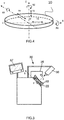
Figure 4 is a perspective view of a preformed surface of an optical lens member illustrating a reference system and the position parameters; -
Figure 5 is a flowchart of the steps of a method according to the invention; and -
Figure 6 is a perspective view of an annular blocking ring. - Elements in the figures are illustrated for simplicity and clarity and have not necessarily been drawn to scale. For example, the dimensions of some of the elements in the figure may be exaggerated relative to other elements to help improve the understanding of the embodiments of the present invention.
- In the sense of the invention, a "Design" is a widely used wording known from the man skilled in the art to designate the set of parameters allowing to define an optical function of a generic optical system; each ophthalmic lens manufacturer has its own designs, particularly for aspherical lens and for progressive lens. As for an example, a progressive lens "design" results of an optimization of the progressive surface so as to restore a presbyope's ability to see clearly at all distances but also to optimally respect all physiological visual functions such as foveal vision, extra-foveal vision, binocular vision and to minimize unwanted astigmatisms. Progressive lens "designs" are tested through rigorous clinical trials before being commercialized.
- In the context of the present invention the term "optical lens member" can refer to a lens blank, an uncut lens, a semi-finished lens. It will be understood that the method can thus be applied to any stage of the manufacturing process of an ophthalmic lens.
- As indicated previously, when one needs to machine a surface of an optical lens one previously to the machining step has the optical lens member blocked on the opposite surface to the surface to be manufactured.
- Typically, a method for manufacturing an optical lens comprises:
- an optical lens member providing step,
- an optical lens member blocking step, and
- a machining step.
- During the optical lens member providing step, an optical lens member is provided, for example a semi-finished optical lens.
- As represented on
figure 1A theoptical lens member 10 has a first surface with a first design, for example a preformed aspherical front surface. In use of the resulting finished optical lens, the preformedfront surface 11 is disposed nearest the object being viewed. Theoptical lens member 10 further comprises asecond surface 12 to be modified by the manufacturing method so as to provide for example theback surface 13 of the finished optical lens, represented by the dotted line.Second surface 12 is machined by a machining tool so that theback surface 13 is orientated with respect to and distanced from thefront surface 11, according to a required optical prescription. - While in this embodiment of the invention, the first surface is the front surface of the lens member and the second surface is the back surface, it will be understood, that in alternative embodiments of the invention the first surface may be the back surface of the lens member and the second surface may be the front surface.
- Furthermore, while in this embodiment of the invention, the back surface of the optical lens is formed by the manufacturing method, it will be understood, that in alternative embodiments of the invention both or either surfaces of the lens may be formed by the manufacturing method.
- Moreover, although the
surface 13 to be manufactured is represented inFigure 1A as concave, it will be appreciated that thissurface 13 could equally well be convex or any other curved surface. - With reference to Figure IB,
reference markings 111 are provided on thefirst surface 11 of thelens member 10 as reference features for defining a first reference system for positioning of the first design of the first surface. - The
reference markings 111 may be engraved markings have a depth of a few micrometers so as to limit the risk of disturbing the wearer of the resulting finished optical lens. The reference markings may also be temporary markings, for example using a removable ink. Advantageously, thereference markings 111 are positioned such as they do not appear on resulting finished optical lens after edging operations. - As illustrated on
figure 2 , during the optical lens member blocking step, thefirst surface 11 of thelens member 10 is placed on alens blocking ring 22. A blocking cast material is poured in thecavity 24 defined by thefirst surface 11, thelens blocking ring 22 and a top surface (not represented) of aninsert 21. - Although on
figure 2 , theoptical lens member 10 is represented has having afirst surface 11 spherical, the invention is most advantageous foroptical lens member 10 having an aspherical first surface. - As illustrated on
figure 3 , a blockingstation 30 may be used for the optical lens member blocking step. The blockingstation 30 comprises a clampingarm 35 which may be moved from a free position to a clamping position in which it holds thelens member 10 in place on thelens blocking ring 22. Blockingstation 30 also includes adigital camera 36 for taking an image of the positioning of thelens member 10 on the blockingring 22, and ascreen 37 for viewing the image from thedigital camera 36. Thelens member 10 may also be directly viewed by an operator without using thedigital camera 36. - Once, the operator has positioned the lens member in a predetermined position on the blocking ring the optical lens is clamped using the
clamping arm 35. The casting material may then be poured in thecavity 24. - So as to place the lens member in a predetermined position; the operator uses the digital camera and the
screen 37 to visualize reference markings on thefirst surface 11 of thelens member 10. The image of thereference markings 111 on thefirst surface 11 of thelens member 10 is compared to a computer-generated target on thescreen 37. The operator places the lens member so that the image of thereference markings 111 of thefirst surface 11 of thelens member 10 and the computer-generated target superpose. - As illustrated on
figure 4 , the position of thelens member 10 is defined in a reference system comprising a main axis Z perpendicular to a main plane (X, Y) defined by two axes X, Y perpendicular to each other and to the main axis Z. The position of the lens member, in particular of thefirst surface 11 of thelens member 10 in such reference system is defined by six parameters. Among the six parameters, three are translation parameters TX, TY and TZ along each axis X, Y, and Z and three are rotation parameters RX, RY, and RZ about each of the axis X, Y, and Z. The reference system is also shown onfigure 3 . - When positioning the lens blank on the blocking ring using the blocking
station 30, an operator controls only three of the six parameters, i.e. the rotation RZ about the main axis Z and the translations TX and TY along the axis X and Y. Three complementary position parameters TZ, RX and RY are constrained by the shape of the first face and the shape of the bearing zone. - The other three complementary position parameters TZ, RX and RY are to be determined accurately using computer means and an appropriate method. When the placed surface of the optical lens member is aspherical the three rotation parameters are of great importance.
- The method of the invention is such an appropriate method.
- The method of the invention may be implemented by computer means and comprises finding a trio of points of the bearing zone that forms a triangle comprising the projection on the main plane of the point of application of said force; and a position of the optical lens having a virtual contact between the placed known surface and the ring at the location of said trios of points.
- As illustrated on
figure 5 , according to an embodiment of the invention the method according to the invention comprises: - a reference system providing step S1,
- a blocking ring data providing step S2,
- an optical lens member surface data providing step S3,
- a position parameters providing step S4,
- a sampling step S5,
- a trio selection step S6,
- a repositioning step S7, and
- a selection step S8
- During the reference system providing step S1, a reference system comprising a main axis (Z) perpendicular to a main plane (X, Y) is provided. The main plane (X,Y) is defined by two axes perpendicular to each other and to the main axis (Z). The center (O) of such reference system is defined as the intersection point of the main axis (Z) with the main plane (X, Y).
- The main axis (Z) corresponds to the main direction of the force applied on the optical lens member, for example by the clamping
arm 35. - During the blocking ring data providing step S2, blocking ring data is provided. The blocking ring data represents at least the bearing zone of the blocking in the reference system. The bearing zone is the part of the blocking ring arranged to bear at least partially the placed known surface of the optical lens member.
- Different type of blocking ring may be used during the optical lens member blocking step.
- As disclosed in
U.S. Pat. No. 4,714,232 the blocking ring may be in the form of a bearing ring having three bearing areas for contact with a semi-finished blank arranged circumferentially around an axis and at the vertices of an isosceles triangle, each bearing area having a plurality of facets which conjointly form a globally convex combination. - Although this solution minimizes the risk associated with the appearance of prism during positioning of the semi-finished blank, the risk is not eliminated entirely and producing such type of blocking ring is very expensive.
- Another type of blocking ring comprises three pegs, each peg having a cylindrical body that is extended by a spherical surface head. The first surface of the optical lens is placed on the spherical surface heads. The use of such blocking ring combined with an appropriate method provides a good control of the blocking position of the optical lens member. However, such blocking ring remains expensive to produce.
- As represented on
figure 6 , a production blocking ring may simply comprise anannular bearing zone 23 having globally a circular symmetry about an axis Z. The bearing zone is arranged to bear at least partially the placed surface of the optical lens member when said optical lens member is placed on the blocking ring. - According to an embodiment of the invention, the bearing zone is located within the main plane and the center of the reference system is located at a geometrical center of the bearing
zone 23. - According to an embodiment of the invention, the blocking ring has a cylinder shape whose revolution axis is parallel to the main axis (Z). The blocking ring may have a constant height along the main axis. The shapes of the blocking rings tend to be as simple as possible so as to reduce the cost of such blocking ring.
- When the lens member is clamped against the lens blocking ring, only part of the blocking ring is in contact with the places known surface of the lens member.
- Indeed, the clamping
arm 35 of the blocking station usually has an offset, i.e. the point of the second surface of the lens member where the clamping arm is clamped does not correspond to the center of the lens member and the placed known surface of the lens member is usually asymmetric. - Therefore, the bearing zone may represent only part of the surface of the blocking ring: the part that is to be in contact with the placed known surface of the lens member.
- As represented on
figure 6 , according to an embodiment of the invention, the bearingzone 23 has a circular shape and may be comprised in a plane perpendicular to the main axis (Z). - According to an embodiment of the invention, the bearing zone data represent an arc of the blocking ring, the arc having an angle greater than or equal to 60°, for example greater than or equal to 120°, for example greater than 170°, and smaller than or equal to 300°, for example smaller than or equal to 240°, for example smaller than 190°. The summit of the arc is positioned at the geometrical center of the bearing zone.
- The blocking ring data comprises data representing, in the reference system provided during the reference system providing step, a plurality of point of the bearing zone. The plurality of points comprises at least three points, for example at least 10 points, for example the blocking ring data comprise one point per degrees over the bearing area.
- According to an embodiment, the blocking ring data comprise points arranged so as they are spaced by an angular distance greater than or equal to 0.5° and smaller than or equal to 2°. The reference of the angles is the center of the blocking ring.
- During the optical lens member surface data providing step S3, optical lens member surface data are provided. The optical lens member surface data represent the known surface of the optical lens to be placed on the blocking ring. The optical lens member surface data are expressed in the reference system.
- For example, the optical lens member surface data represent the
first surface 11 of thelens member 10. According to an embodiment of the invention, the optical lens member surface data is a representation at least twice derivable of the placed surface of the optical lens member. The optical lens surface member surface data may be a surface function representation of the optical surface, using for example NURBS representations, i.e. NonUniform Rational Basis Splines. - As indicated previously, according to an embodiment of the invention, the placed surface may be asymmetric, for example aspherical.
- During the position parameters providing step S4, position parameters of the placed surface are provided. The position parameters define the position of a reference point of the surface of the optical lens to be placed on the blocking ring in the main plane of the reference system and the orientation of said surface about the main axis of the reference system. The position parameters correspond to the parameters the operator may control when placing the lens member on the blocking ring, i.e. the rotation RZ about the main axis Z and the translations TX and TY along the axis X and Y. RX, RY and TZ are controlled through the clamping arm and contact with the blocking ring, and TX, TY and RZ are controlled by an operator by aligning a reference point of the first surface on a reference marks located on the blocking station.
- According to an embodiment of the invention, the optical lens member is used to manufacture an ophthalmic lens.
- The reference point of the surface of the optical lens member to be placed on the center of the blocking ring may be any point of the surface, for example when the optical lens is a progressive ophthalmic lens, the reference point is the prism reference point. However, the geometrical center of the first surface or the barycenter of the first surface can be used as reference point.
- During the sampling step S5, the bearing zone is sampled into a plurality of points, the points being regroup in a set of trios.
- For example, the bearing zone is sampled with a 30° angular sampling. When the bearing zone is annular such sampling defines 12 points equally distributed.
- During the trio selection step S6 trios of points whose projection on the main plane form a triangle are selected.
- According to the embodiment of a sampling with a 30° angular sampling these forms 220 trio of points.
- During the trio selection step, only the trios of points forming a triangle comprising the projection on the main plane of the point of application of force are selected.
- The method of the invention may comprise an initial position determining step S6b during which the position of the placed surface of the optical lens member is determined. In other words, using the optical lens member surface data, the blocking ring data and the position parameter, an initial position of the placed surface of the optical lens member relative to the blocking ring is determined.
- For example, the blocking ring is placed in the main plane (X,Y) and perpendicular to the main axis Z. The placed surface is placed relatively to the blocking ring according to the three positioning parameters. The three other parameters TZ, RX, and RY may be given an arbitrary value under the condition that the placed surface of the optical lens is above the blocking ring.
- According to an embodiment of the invention, the optical lens is a progressive multifocal ophthalmic lens and during the initial positioning step, the placed surface is oriented so as to have the near vision part of the progressive multifocal ophthalmic lens facing the at least part of the surface of the blocking ring. In other words, the parameter corresponding to the rotation about the main axis Z is so that the placed surface is oriented so as to have the near vision part of the progressive multifocal ophthalmic lens facing the bearing zone of the blocking ring. According to such embodiment, the optical lens may be placed so that the clamping arm in the clamping position pushes against the near vision part of the progressive multifocal ophthalmic lens.
- According to an embodiment of the invention, the optical lens is a progressive multifocal ophthalmic lens and during the initial positioning step, the placed surface is oriented so as to have the far vision part of the progressive multifocal ophthalmic lens facing the at least part of the surface of the blocking ring. In other words, the parameter corresponding to the rotation about the main axis Z is so that the placed surface is oriented so as to have the far vision part of the progressive multifocal ophthalmic lens facing the bearing zone of the blocking ring. According to such embodiment, the optical lens may be placed so that the clamping arm in the clamping position pushes against the far vision part of the progressive multifocal ophthalmic lens. Since the far vision part of the progressive multifocal ophthalmic lens has a surface close to a sphere, the contact between the optical surface and the blocking ring is easier and the risk of a having some of the cast material leaking during the blocking steps is reduced.
- During the repositioning step S7, the known surface of the optical lens is virtually rotated about the two perpendicular axes (X;Y) so that the plane formed by the three projected points of the each triple of points on the known surface of the optical lens is parallel to the plan formed by the three projected points of said each triple of points on the ring, and the known surface is virtually translated along the main axis (Z) to have a virtual contact between the tilted surface and the ring at the location of said trios of points.
- Here, by "virtually", one intends "by calculations performed for example by computer means".
- During the selection step the repositioning step is repeated for each trio of points, eliminating each trio of points for which the difference in position along the main axis between the points of the blocking ring data and the corresponding points of the known surface of the optical lens is negative, and finally selecting one of the remaining trios as the final trio of point.
- In other words, no collision between the known surface of the optical lens member and the ring is accepted, i.e. no point of the known surface is to be below a point of the ring.
- The final trio of points may be selected as being the one of the remaining trios of points corresponding to a position having an orientation parameters (RX, RY) defining the orientation about one of the axis defining the main plan the closest to the average orientation parameter over the positions corresponding to the remaining trios of points.
- For example, for each remaining trios of points the orientation parameters RX and RY of the corresponding position are calculated. The orientation parameter having the greatest amplitude among the remaining trio of points is selected.
- The final trio of points is selected among the remaining trios of points corresponding to a position having the selected orientation parameter the closest from the average value of said selected orientation parameter over the positions corresponding to the remaining trio of points.
- Once the trio of points that minimizes the difference in position along the main (Z) has been determined, the values of the position parameters TZ, RX, and RY combined with the values of the position parameters RZ, TX and TY, allows calculating an accurate position for the placed surface with respect to the blocking ring and then to the lens blocker. Thus, when machining the second surface of the optical lens member, the positioning errors between the two optical surfaces of the lens can be reduced, because the position of first surface was better anticipated in the calculation.
- Advantageously, the overall accuracy of the manufacturing method is increased.
- According to an embodiment of the invention, the sampling, the trio selection and the repositioning steps may be repeated by sampling the bearing zone with a smaller sampling around each of the points of the selected trio of points.
- For example, when repeating the trio selection and the repositioning steps the sampling is divided by two.
- According to such embodiment, the optimization of the method of the invention may be stopped when sampling is smaller or equal to 2°. In other words, the trio selection and the repositioning steps are repeated until the sampling is smaller or equal to 2°.
- The method of the invention may also be carried out until the values of the rotation angles about the two perpendicular axes (X;Y) differ of less than 5% from the values of said rotation angles determined at the previous repetition.
- Although the stop criteria are described as independent the method of the invention may be stopped when the one of the two criteria is reached, i.e. sampling smaller or equal to 2° and the values of the rotation angles about the two perpendicular axes (X;Y) differ of less than 5% from the values of said rotation angles determined at the previous repetition
- Although presented as an iterative process, it will be appreciated that optimization used in the method of the invention may be of any type known of the person skilled in the art.
- While the foregoing examples have been described with reference to the manufacture of an ophthalmic lens, it will be appreciated that the method of the invention may be applied more generally to the manufacture of other types of optical lens, for example optical lens used in telescopes and the like, or contact lens.
- Many further modifications and variations will suggest themselves to those skilled in the art upon making reference to the foregoing illustrative embodiments, which are given by way of example only and which are not intended to limit the scope of the invention, that being determined solely by the appended claims.
- In the claims, the word "comprising" does not exclude other elements or steps, and the indefinite article "a" or "an" does not exclude a plurality. The mere fact that different features are recited in mutually different dependent claims does not indicate that a combination of these features cannot be advantageously used. Any reference signs in the claims should not be construed as limiting the scope of the invention.
Claims (13)
- Method implemented by computer means, for determining the position of an optical lens member having a surface placed on a lens blocking ring, the blocking ring comprising a bearing zone arranged to bear at least partially a placed known surface of the optical lens member when said known surface of the optical lens member is placed on the lens blocking ring and hold by a force applied on the optical lens member, the method comprising:- a reference system providing step (S1) during which a reference system is provided, the reference system comprises a main axis (Z) perpendicular to a main plane (X,Y) defined by two axes perpendicular to each other and to the main axis (Z), the main axis (Z) corresponding to the main direction of the force applied on the optical lens member,- a blocking ring data providing step (S2) during which blocking ring data is provided, the blocking ring data representing the bearing zone in the reference system,- an optical lens member surface data providing step (S3), during which optical lens member surface data is provided, the optical lens member surface data representing, in the reference system, the known surface of the optical lens member to be placed on the blocking ring,- a position parameters providing step (S4) during which position parameters are provided, the position parameters (TX, TY, RZ) defining a position of a reference point of the known surface with respect to the main plane of the reference system and an orientation, about the main axis of said known surface at said reference point,- a sampling step (S5) during which the bearing zone is sampled into a plurality of points, the points being regrouped in a set of trios, the method characterised in that it comprises the following further steps:- a trio selection step (S6) during which trios of points whose projection on the main plane form a triangle comprising the projection on the main plane of the point of application of force are selected;- a repositioning step (S7) during which the known surface of the optical lens is virtually rotated about the two perpendicular axes (X;Y) so that the plane formed by the three projected points of the each triple of points on the known surface of the optical lens is parallel to the plan formed by the three projected points of said each triple of points on the ring, and the known surface is virtually translated along the main axis (Z) to have a virtual contact between the tilted surface and the ring at the location of said trios of points;- a selection step (S8) during which the repositioning step is repeated for each trio of points, eliminating each trio of points for which the difference in position along the main axis between the points of the blocking ring data and the corresponding points of the known surface of the optical lens is negative, and finally selecting one of the remaining trios as the final trio of points.
- The method according to claim 1, wherein the blocking ring has an axis of symmetry that corresponds to the main axis (Z).
- The method according to the preceding claim, wherein during the sampling step the bearing zone is sampled with a 30° angular sampling.
- The method according to any of the preceding claims, wherein the sampling, the trio selection and the repositioning steps are repeated by sampling the bearing zone with a smaller sampling around each of the points of the selected trio of points.
- The method according to claim 4, wherein when repeating the trio selection and the repositioning steps the sampling is divided by two.
- The method according to any of claims 4 or 5, wherein the trio selection and the repositioning steps are repeated until the sampling is smaller or equal to 2°.
- The method according to any of claims 4 to 6, wherein the trio selection and the repositioning steps are repeated until the values of the rotation angles about the two perpendicular axes (X;Y) differ of less than 5% from the values of said rotation angles determined at the previous repetition.
- The method according to any of the preceding claims, wherein the blocking ring data comprise points spaced by an angular distance greater than or equal to 0.5°and smaller than or equal to 2°.
- The method according to any of the preceding claims, wherein the bearing zone of the blocking ring is comprised in a plane perpendicular to the main axis (Z).
- The method according to any of the preceding claims, wherein the optical lens member is used to manufacture a progressive multifocal ophthalmic lens and the reference point of the known surface is the prism reference point of the progressive multifocal ophthalmic lens.
- The method according to the preceding claim, wherein the known surface is oriented so as to have the near vision part of the progressive multifocal ophthalmic lens facing the bearing zone.
- The method according to claim 10, wherein the known surface is oriented so as to have the far vision part of the progressive multifocal ophthalmic lens facing the bearing zone.
- A method of manufacturing an optical surface of an optical lens comprising:- an optical lens member providing step, during which an optical lens member having a first optical surface and a second optical surface to be manufactured is provided,- a blocking step during which the first surface of the optical lens member is placed on a blocking ring and blocked to a holding lens member,- a manufacturing step during which the second surface of the optical lens is manufactured according to manufacturing parameters,
wherein the position of the first surface of the optical lens member on the blocking ring at the blocking step is determined using a method according to any of claims 1 to 12.
Priority Applications (6)
| Application Number | Priority Date | Filing Date | Title |
|---|---|---|---|
| EP17306029.4A EP3437797B1 (en) | 2017-08-02 | 2017-08-02 | A method of determining the position of an optical lens member |
| PL17306029T PL3437797T3 (en) | 2017-08-02 | 2017-08-02 | A method of determining the position of an optical lens member |
| PCT/EP2018/070565 WO2019025352A1 (en) | 2017-08-02 | 2018-07-30 | A method of determining the position of an optical lens member |
| CN201880039385.9A CN110740837B (en) | 2017-08-02 | 2018-07-30 | Method for determining the position of an optical lens member |
| BR112019024671-1A BR112019024671A2 (en) | 2017-08-02 | 2018-07-30 | METHOD OF DETERMINING THE POSITION OF AN OPTICAL LENS MEMBER |
| US16/623,895 US11964355B2 (en) | 2017-08-02 | 2018-07-30 | Method of determining the position of an optical lens member |
Applications Claiming Priority (1)
| Application Number | Priority Date | Filing Date | Title |
|---|---|---|---|
| EP17306029.4A EP3437797B1 (en) | 2017-08-02 | 2017-08-02 | A method of determining the position of an optical lens member |
Publications (2)
| Publication Number | Publication Date |
|---|---|
| EP3437797A1 EP3437797A1 (en) | 2019-02-06 |
| EP3437797B1 true EP3437797B1 (en) | 2020-05-13 |
Family
ID=59626534
Family Applications (1)
| Application Number | Title | Priority Date | Filing Date |
|---|---|---|---|
| EP17306029.4A Active EP3437797B1 (en) | 2017-08-02 | 2017-08-02 | A method of determining the position of an optical lens member |
Country Status (5)
| Country | Link |
|---|---|
| EP (1) | EP3437797B1 (en) |
| CN (1) | CN110740837B (en) |
| BR (1) | BR112019024671A2 (en) |
| PL (1) | PL3437797T3 (en) |
| WO (1) | WO2019025352A1 (en) |
Family Cites Families (14)
| Publication number | Priority date | Publication date | Assignee | Title |
|---|---|---|---|---|
| FR2576820B1 (en) | 1985-02-01 | 1989-04-07 | Essilor Int | SUPPORT RING FOR FIXING A MOUNTING BLOCK ON THE FINISHED SIDE WITH A PROGRESSIVELY VARIABLE CURVE OF A SEMI-FINISHED BLANK OF A PALLET, SUCH AS AN OPHTHALMIC LENS OR MOLD |
| US4856234A (en) * | 1988-02-26 | 1989-08-15 | Research Machine Center, Inc. | Optical lens manufacturing apparatus and method |
| JP3966696B2 (en) * | 2001-03-26 | 2007-08-29 | 株式会社ニデック | Cup mounting device |
| US20040099971A1 (en) * | 2002-11-25 | 2004-05-27 | Technology Resource International Corporation | Lens molds and method of using the same |
| FR2983313B1 (en) * | 2011-11-29 | 2014-06-27 | Essilor Int | OPHTHALMIC LENS HOLDER FOR CENTERING DEVICE |
| FR2997330B1 (en) * | 2012-10-30 | 2015-04-03 | Essilor Int | PROCESS FOR THE MANUFACTURE OF OPHTHALMIC LENSES |
| MX2015008530A (en) * | 2012-12-31 | 2015-09-10 | Essilor Int | A method of determining the blocking position of an optical lens. |
| WO2014131878A1 (en) * | 2013-03-01 | 2014-09-04 | Essilor International (Compagnie Generale D'optique) | Method for providing a referencing element to an optical lens member |
| AU2014222673B2 (en) * | 2013-03-01 | 2017-09-28 | Essilor International | Optical lens member comprising a sub-surface referencing element |
| JP6236313B2 (en) * | 2013-12-26 | 2017-11-22 | ホヤ レンズ タイランド リミテッドHOYA Lens Thailand Ltd | Block device, spectacle lens manufacturing method and program |
| CN105916669B (en) * | 2014-01-22 | 2017-12-22 | 埃西勒国际通用光学公司 | Method for being optimized to one group of optical mirror slip blank |
| EP3002114B1 (en) * | 2014-09-30 | 2017-03-01 | Essilor International (Compagnie Generale D'optique) | Method for optimizing the position of an optical lens in a lens blank |
| CN105690187B (en) * | 2016-02-06 | 2018-03-27 | 苏州大学 | The processing method of off-axis aspheric mirror |
| CN106425750B (en) * | 2016-08-27 | 2018-04-20 | 浙江宝乐维科技有限公司 | The clamping jig and clamping process of eyeglass |
-
2017
- 2017-08-02 PL PL17306029T patent/PL3437797T3/en unknown
- 2017-08-02 EP EP17306029.4A patent/EP3437797B1/en active Active
-
2018
- 2018-07-30 CN CN201880039385.9A patent/CN110740837B/en active Active
- 2018-07-30 WO PCT/EP2018/070565 patent/WO2019025352A1/en active Application Filing
- 2018-07-30 BR BR112019024671-1A patent/BR112019024671A2/en unknown
Non-Patent Citations (1)
| Title |
|---|
| None * |
Also Published As
| Publication number | Publication date |
|---|---|
| CN110740837B (en) | 2021-08-17 |
| US20210146495A1 (en) | 2021-05-20 |
| EP3437797A1 (en) | 2019-02-06 |
| PL3437797T3 (en) | 2020-11-16 |
| WO2019025352A1 (en) | 2019-02-07 |
| BR112019024671A2 (en) | 2020-06-16 |
| CN110740837A (en) | 2020-01-31 |
Similar Documents
| Publication | Publication Date | Title |
|---|---|---|
| EP2938457B1 (en) | A method of determining the blocking position of an optical lens | |
| EP2367657B1 (en) | A method of and an apparatus for manufacturing an optical lens | |
| JP6377065B2 (en) | Method for manufacturing ophthalmic lenses by machining | |
| JP6321665B2 (en) | Method for manufacturing an optical lens and assembly for manufacturing such a lens | |
| US10668590B2 (en) | Method of and an apparatus for manufacturing an optical lens including compensating for relative positioning shift between first and second reference frames | |
| US9104045B2 (en) | Method of determining parameters for fitting an ophthalmic lens to a frame | |
| JP6272778B2 (en) | Method for manufacturing an optical lens | |
| EP3437797B1 (en) | A method of determining the position of an optical lens member | |
| US11964355B2 (en) | Method of determining the position of an optical lens member | |
| EP3628441A1 (en) | Semi-finished lens, method and device for manufacturing an optical lens |
Legal Events
| Date | Code | Title | Description |
|---|---|---|---|
| PUAI | Public reference made under article 153(3) epc to a published international application that has entered the european phase |
Free format text: ORIGINAL CODE: 0009012 |
|
| STAA | Information on the status of an ep patent application or granted ep patent |
Free format text: STATUS: THE APPLICATION HAS BEEN PUBLISHED |
|
| AK | Designated contracting states |
Kind code of ref document: A1 Designated state(s): AL AT BE BG CH CY CZ DE DK EE ES FI FR GB GR HR HU IE IS IT LI LT LU LV MC MK MT NL NO PL PT RO RS SE SI SK SM TR |
|
| AX | Request for extension of the european patent |
Extension state: BA ME |
|
| STAA | Information on the status of an ep patent application or granted ep patent |
Free format text: STATUS: REQUEST FOR EXAMINATION WAS MADE |
|
| 17P | Request for examination filed |
Effective date: 20190715 |
|
| RBV | Designated contracting states (corrected) |
Designated state(s): AL AT BE BG CH CY CZ DE DK EE ES FI FR GB GR HR HU IE IS IT LI LT LU LV MC MK MT NL NO PL PT RO RS SE SI SK SM TR |
|
| GRAP | Despatch of communication of intention to grant a patent |
Free format text: ORIGINAL CODE: EPIDOSNIGR1 |
|
| STAA | Information on the status of an ep patent application or granted ep patent |
Free format text: STATUS: GRANT OF PATENT IS INTENDED |
|
| RIC1 | Information provided on ipc code assigned before grant |
Ipc: B24B 13/005 20060101AFI20191217BHEP |
|
| INTG | Intention to grant announced |
Effective date: 20200121 |
|
| GRAS | Grant fee paid |
Free format text: ORIGINAL CODE: EPIDOSNIGR3 |
|
| GRAA | (expected) grant |
Free format text: ORIGINAL CODE: 0009210 |
|
| STAA | Information on the status of an ep patent application or granted ep patent |
Free format text: STATUS: THE PATENT HAS BEEN GRANTED |
|
| AK | Designated contracting states |
Kind code of ref document: B1 Designated state(s): AL AT BE BG CH CY CZ DE DK EE ES FI FR GB GR HR HU IE IS IT LI LT LU LV MC MK MT NL NO PL PT RO RS SE SI SK SM TR |
|
| REG | Reference to a national code |
Ref country code: GB Ref legal event code: FG4D |
|
| REG | Reference to a national code |
Ref country code: CH Ref legal event code: EP |
|
| REG | Reference to a national code |
Ref country code: DE Ref legal event code: R096 Ref document number: 602017016432 Country of ref document: DE |
|
| REG | Reference to a national code |
Ref country code: AT Ref legal event code: REF Ref document number: 1269632 Country of ref document: AT Kind code of ref document: T Effective date: 20200615 |
|
| REG | Reference to a national code |
Ref country code: LT Ref legal event code: MG4D |
|
| REG | Reference to a national code |
Ref country code: NL Ref legal event code: MP Effective date: 20200513 |
|
| PG25 | Lapsed in a contracting state [announced via postgrant information from national office to epo] |
Ref country code: LT Free format text: LAPSE BECAUSE OF FAILURE TO SUBMIT A TRANSLATION OF THE DESCRIPTION OR TO PAY THE FEE WITHIN THE PRESCRIBED TIME-LIMIT Effective date: 20200513 Ref country code: FI Free format text: LAPSE BECAUSE OF FAILURE TO SUBMIT A TRANSLATION OF THE DESCRIPTION OR TO PAY THE FEE WITHIN THE PRESCRIBED TIME-LIMIT Effective date: 20200513 Ref country code: NO Free format text: LAPSE BECAUSE OF FAILURE TO SUBMIT A TRANSLATION OF THE DESCRIPTION OR TO PAY THE FEE WITHIN THE PRESCRIBED TIME-LIMIT Effective date: 20200813 Ref country code: SE Free format text: LAPSE BECAUSE OF FAILURE TO SUBMIT A TRANSLATION OF THE DESCRIPTION OR TO PAY THE FEE WITHIN THE PRESCRIBED TIME-LIMIT Effective date: 20200513 Ref country code: IS Free format text: LAPSE BECAUSE OF FAILURE TO SUBMIT A TRANSLATION OF THE DESCRIPTION OR TO PAY THE FEE WITHIN THE PRESCRIBED TIME-LIMIT Effective date: 20200913 Ref country code: GR Free format text: LAPSE BECAUSE OF FAILURE TO SUBMIT A TRANSLATION OF THE DESCRIPTION OR TO PAY THE FEE WITHIN THE PRESCRIBED TIME-LIMIT Effective date: 20200814 Ref country code: PT Free format text: LAPSE BECAUSE OF FAILURE TO SUBMIT A TRANSLATION OF THE DESCRIPTION OR TO PAY THE FEE WITHIN THE PRESCRIBED TIME-LIMIT Effective date: 20200914 |
|
| PG25 | Lapsed in a contracting state [announced via postgrant information from national office to epo] |
Ref country code: HR Free format text: LAPSE BECAUSE OF FAILURE TO SUBMIT A TRANSLATION OF THE DESCRIPTION OR TO PAY THE FEE WITHIN THE PRESCRIBED TIME-LIMIT Effective date: 20200513 Ref country code: RS Free format text: LAPSE BECAUSE OF FAILURE TO SUBMIT A TRANSLATION OF THE DESCRIPTION OR TO PAY THE FEE WITHIN THE PRESCRIBED TIME-LIMIT Effective date: 20200513 Ref country code: LV Free format text: LAPSE BECAUSE OF FAILURE TO SUBMIT A TRANSLATION OF THE DESCRIPTION OR TO PAY THE FEE WITHIN THE PRESCRIBED TIME-LIMIT Effective date: 20200513 Ref country code: BG Free format text: LAPSE BECAUSE OF FAILURE TO SUBMIT A TRANSLATION OF THE DESCRIPTION OR TO PAY THE FEE WITHIN THE PRESCRIBED TIME-LIMIT Effective date: 20200813 |
|
| REG | Reference to a national code |
Ref country code: AT Ref legal event code: MK05 Ref document number: 1269632 Country of ref document: AT Kind code of ref document: T Effective date: 20200513 |
|
| PG25 | Lapsed in a contracting state [announced via postgrant information from national office to epo] |
Ref country code: NL Free format text: LAPSE BECAUSE OF FAILURE TO SUBMIT A TRANSLATION OF THE DESCRIPTION OR TO PAY THE FEE WITHIN THE PRESCRIBED TIME-LIMIT Effective date: 20200513 Ref country code: AL Free format text: LAPSE BECAUSE OF FAILURE TO SUBMIT A TRANSLATION OF THE DESCRIPTION OR TO PAY THE FEE WITHIN THE PRESCRIBED TIME-LIMIT Effective date: 20200513 |
|
| PG25 | Lapsed in a contracting state [announced via postgrant information from national office to epo] |
Ref country code: ES Free format text: LAPSE BECAUSE OF FAILURE TO SUBMIT A TRANSLATION OF THE DESCRIPTION OR TO PAY THE FEE WITHIN THE PRESCRIBED TIME-LIMIT Effective date: 20200513 Ref country code: CZ Free format text: LAPSE BECAUSE OF FAILURE TO SUBMIT A TRANSLATION OF THE DESCRIPTION OR TO PAY THE FEE WITHIN THE PRESCRIBED TIME-LIMIT Effective date: 20200513 Ref country code: SM Free format text: LAPSE BECAUSE OF FAILURE TO SUBMIT A TRANSLATION OF THE DESCRIPTION OR TO PAY THE FEE WITHIN THE PRESCRIBED TIME-LIMIT Effective date: 20200513 Ref country code: RO Free format text: LAPSE BECAUSE OF FAILURE TO SUBMIT A TRANSLATION OF THE DESCRIPTION OR TO PAY THE FEE WITHIN THE PRESCRIBED TIME-LIMIT Effective date: 20200513 Ref country code: DK Free format text: LAPSE BECAUSE OF FAILURE TO SUBMIT A TRANSLATION OF THE DESCRIPTION OR TO PAY THE FEE WITHIN THE PRESCRIBED TIME-LIMIT Effective date: 20200513 Ref country code: AT Free format text: LAPSE BECAUSE OF FAILURE TO SUBMIT A TRANSLATION OF THE DESCRIPTION OR TO PAY THE FEE WITHIN THE PRESCRIBED TIME-LIMIT Effective date: 20200513 Ref country code: EE Free format text: LAPSE BECAUSE OF FAILURE TO SUBMIT A TRANSLATION OF THE DESCRIPTION OR TO PAY THE FEE WITHIN THE PRESCRIBED TIME-LIMIT Effective date: 20200513 |
|
| REG | Reference to a national code |
Ref country code: DE Ref legal event code: R097 Ref document number: 602017016432 Country of ref document: DE |
|
| PG25 | Lapsed in a contracting state [announced via postgrant information from national office to epo] |
Ref country code: SK Free format text: LAPSE BECAUSE OF FAILURE TO SUBMIT A TRANSLATION OF THE DESCRIPTION OR TO PAY THE FEE WITHIN THE PRESCRIBED TIME-LIMIT Effective date: 20200513 |
|
| PLBE | No opposition filed within time limit |
Free format text: ORIGINAL CODE: 0009261 |
|
| STAA | Information on the status of an ep patent application or granted ep patent |
Free format text: STATUS: NO OPPOSITION FILED WITHIN TIME LIMIT |
|
| PG25 | Lapsed in a contracting state [announced via postgrant information from national office to epo] |
Ref country code: MC Free format text: LAPSE BECAUSE OF FAILURE TO SUBMIT A TRANSLATION OF THE DESCRIPTION OR TO PAY THE FEE WITHIN THE PRESCRIBED TIME-LIMIT Effective date: 20200513 |
|
| REG | Reference to a national code |
Ref country code: CH Ref legal event code: PL |
|
| 26N | No opposition filed |
Effective date: 20210216 |
|
| PG25 | Lapsed in a contracting state [announced via postgrant information from national office to epo] |
Ref country code: LU Free format text: LAPSE BECAUSE OF NON-PAYMENT OF DUE FEES Effective date: 20200802 Ref country code: LI Free format text: LAPSE BECAUSE OF NON-PAYMENT OF DUE FEES Effective date: 20200831 Ref country code: CH Free format text: LAPSE BECAUSE OF NON-PAYMENT OF DUE FEES Effective date: 20200831 |
|
| REG | Reference to a national code |
Ref country code: BE Ref legal event code: MM Effective date: 20200831 |
|
| PG25 | Lapsed in a contracting state [announced via postgrant information from national office to epo] |
Ref country code: SI Free format text: LAPSE BECAUSE OF FAILURE TO SUBMIT A TRANSLATION OF THE DESCRIPTION OR TO PAY THE FEE WITHIN THE PRESCRIBED TIME-LIMIT Effective date: 20200513 |
|
| PG25 | Lapsed in a contracting state [announced via postgrant information from national office to epo] |
Ref country code: BE Free format text: LAPSE BECAUSE OF NON-PAYMENT OF DUE FEES Effective date: 20200831 Ref country code: IE Free format text: LAPSE BECAUSE OF NON-PAYMENT OF DUE FEES Effective date: 20200802 |
|
| PG25 | Lapsed in a contracting state [announced via postgrant information from national office to epo] |
Ref country code: TR Free format text: LAPSE BECAUSE OF FAILURE TO SUBMIT A TRANSLATION OF THE DESCRIPTION OR TO PAY THE FEE WITHIN THE PRESCRIBED TIME-LIMIT Effective date: 20200513 Ref country code: MT Free format text: LAPSE BECAUSE OF FAILURE TO SUBMIT A TRANSLATION OF THE DESCRIPTION OR TO PAY THE FEE WITHIN THE PRESCRIBED TIME-LIMIT Effective date: 20200513 Ref country code: CY Free format text: LAPSE BECAUSE OF FAILURE TO SUBMIT A TRANSLATION OF THE DESCRIPTION OR TO PAY THE FEE WITHIN THE PRESCRIBED TIME-LIMIT Effective date: 20200513 |
|
| PG25 | Lapsed in a contracting state [announced via postgrant information from national office to epo] |
Ref country code: MK Free format text: LAPSE BECAUSE OF FAILURE TO SUBMIT A TRANSLATION OF THE DESCRIPTION OR TO PAY THE FEE WITHIN THE PRESCRIBED TIME-LIMIT Effective date: 20200513 |
|
| P01 | Opt-out of the competence of the unified patent court (upc) registered |
Effective date: 20230525 |
|
| PGFP | Annual fee paid to national office [announced via postgrant information from national office to epo] |
Ref country code: IT Payment date: 20230822 Year of fee payment: 7 Ref country code: GB Payment date: 20230828 Year of fee payment: 7 |
|
| PGFP | Annual fee paid to national office [announced via postgrant information from national office to epo] |
Ref country code: PL Payment date: 20230719 Year of fee payment: 7 Ref country code: FR Payment date: 20230825 Year of fee payment: 7 Ref country code: DE Payment date: 20230829 Year of fee payment: 7 |