EP3437742A1 - Bonding device and upper transport unit - Google Patents
Bonding device and upper transport unit Download PDFInfo
- Publication number
- EP3437742A1 EP3437742A1 EP18185882.0A EP18185882A EP3437742A1 EP 3437742 A1 EP3437742 A1 EP 3437742A1 EP 18185882 A EP18185882 A EP 18185882A EP 3437742 A1 EP3437742 A1 EP 3437742A1
- Authority
- EP
- European Patent Office
- Prior art keywords
- link
- end portion
- upper transport
- support arm
- transport roller
- Prior art date
- Legal status (The legal status is an assumption and is not a legal conclusion. Google has not performed a legal analysis and makes no representation as to the accuracy of the status listed.)
- Withdrawn
Links
- 230000007246 mechanism Effects 0.000 claims abstract description 71
- 230000007723 transport mechanism Effects 0.000 claims abstract description 30
- 238000011144 upstream manufacturing Methods 0.000 claims abstract description 26
- 230000008878 coupling Effects 0.000 claims description 103
- 238000010168 coupling process Methods 0.000 claims description 103
- 238000005859 coupling reaction Methods 0.000 claims description 103
- 238000001514 detection method Methods 0.000 claims description 57
- 239000000853 adhesive Substances 0.000 claims description 30
- 230000001070 adhesive effect Effects 0.000 claims description 30
- 230000032258 transport Effects 0.000 description 291
- 238000010586 diagram Methods 0.000 description 6
- 230000005540 biological transmission Effects 0.000 description 4
- 230000008859 change Effects 0.000 description 4
- 238000012423 maintenance Methods 0.000 description 3
- 230000003287 optical effect Effects 0.000 description 3
- 230000002093 peripheral effect Effects 0.000 description 3
- 239000004831 Hot glue Substances 0.000 description 1
- 230000004048 modification Effects 0.000 description 1
- 238000012986 modification Methods 0.000 description 1
Images





Classifications
-
- B—PERFORMING OPERATIONS; TRANSPORTING
- B29—WORKING OF PLASTICS; WORKING OF SUBSTANCES IN A PLASTIC STATE IN GENERAL
- B29C—SHAPING OR JOINING OF PLASTICS; SHAPING OF MATERIAL IN A PLASTIC STATE, NOT OTHERWISE PROVIDED FOR; AFTER-TREATMENT OF THE SHAPED PRODUCTS, e.g. REPAIRING
- B29C66/00—General aspects of processes or apparatus for joining preformed parts
- B29C66/80—General aspects of machine operations or constructions and parts thereof
- B29C66/87—Auxiliary operations or devices
- B29C66/872—Starting or stopping procedures
-
- B—PERFORMING OPERATIONS; TRANSPORTING
- B65—CONVEYING; PACKING; STORING; HANDLING THIN OR FILAMENTARY MATERIAL
- B65H—HANDLING THIN OR FILAMENTARY MATERIAL, e.g. SHEETS, WEBS, CABLES
- B65H37/00—Article or web delivery apparatus incorporating devices for performing specified auxiliary operations
- B65H37/02—Article or web delivery apparatus incorporating devices for performing specified auxiliary operations for applying adhesive
-
- B—PERFORMING OPERATIONS; TRANSPORTING
- B05—SPRAYING OR ATOMISING IN GENERAL; APPLYING FLUENT MATERIALS TO SURFACES, IN GENERAL
- B05C—APPARATUS FOR APPLYING FLUENT MATERIALS TO SURFACES, IN GENERAL
- B05C5/00—Apparatus in which liquid or other fluent material is projected, poured or allowed to flow on to the surface of the work
- B05C5/02—Apparatus in which liquid or other fluent material is projected, poured or allowed to flow on to the surface of the work the liquid or other fluent material being discharged through an outlet orifice by pressure, e.g. from an outlet device in contact or almost in contact, with the work
- B05C5/0208—Apparatus in which liquid or other fluent material is projected, poured or allowed to flow on to the surface of the work the liquid or other fluent material being discharged through an outlet orifice by pressure, e.g. from an outlet device in contact or almost in contact, with the work for applying liquid or other fluent material to separate articles
-
- B—PERFORMING OPERATIONS; TRANSPORTING
- B29—WORKING OF PLASTICS; WORKING OF SUBSTANCES IN A PLASTIC STATE IN GENERAL
- B29C—SHAPING OR JOINING OF PLASTICS; SHAPING OF MATERIAL IN A PLASTIC STATE, NOT OTHERWISE PROVIDED FOR; AFTER-TREATMENT OF THE SHAPED PRODUCTS, e.g. REPAIRING
- B29C65/00—Joining or sealing of preformed parts, e.g. welding of plastics materials; Apparatus therefor
- B29C65/48—Joining or sealing of preformed parts, e.g. welding of plastics materials; Apparatus therefor using adhesives, i.e. using supplementary joining material; solvent bonding
- B29C65/52—Joining or sealing of preformed parts, e.g. welding of plastics materials; Apparatus therefor using adhesives, i.e. using supplementary joining material; solvent bonding characterised by the way of applying the adhesive
- B29C65/524—Joining or sealing of preformed parts, e.g. welding of plastics materials; Apparatus therefor using adhesives, i.e. using supplementary joining material; solvent bonding characterised by the way of applying the adhesive by applying the adhesive from an outlet device in contact with, or almost in contact with, the surface of the part to be joined
-
- B—PERFORMING OPERATIONS; TRANSPORTING
- B29—WORKING OF PLASTICS; WORKING OF SUBSTANCES IN A PLASTIC STATE IN GENERAL
- B29C—SHAPING OR JOINING OF PLASTICS; SHAPING OF MATERIAL IN A PLASTIC STATE, NOT OTHERWISE PROVIDED FOR; AFTER-TREATMENT OF THE SHAPED PRODUCTS, e.g. REPAIRING
- B29C66/00—General aspects of processes or apparatus for joining preformed parts
- B29C66/01—General aspects dealing with the joint area or with the area to be joined
- B29C66/05—Particular design of joint configurations
- B29C66/10—Particular design of joint configurations particular design of the joint cross-sections
- B29C66/11—Joint cross-sections comprising a single joint-segment, i.e. one of the parts to be joined comprising a single joint-segment in the joint cross-section
- B29C66/112—Single lapped joints
- B29C66/1122—Single lap to lap joints, i.e. overlap joints
-
- B—PERFORMING OPERATIONS; TRANSPORTING
- B29—WORKING OF PLASTICS; WORKING OF SUBSTANCES IN A PLASTIC STATE IN GENERAL
- B29C—SHAPING OR JOINING OF PLASTICS; SHAPING OF MATERIAL IN A PLASTIC STATE, NOT OTHERWISE PROVIDED FOR; AFTER-TREATMENT OF THE SHAPED PRODUCTS, e.g. REPAIRING
- B29C66/00—General aspects of processes or apparatus for joining preformed parts
- B29C66/40—General aspects of joining substantially flat articles, e.g. plates, sheets or web-like materials; Making flat seams in tubular or hollow articles; Joining single elements to substantially flat surfaces
- B29C66/41—Joining substantially flat articles ; Making flat seams in tubular or hollow articles
- B29C66/43—Joining a relatively small portion of the surface of said articles
-
- B—PERFORMING OPERATIONS; TRANSPORTING
- B29—WORKING OF PLASTICS; WORKING OF SUBSTANCES IN A PLASTIC STATE IN GENERAL
- B29C—SHAPING OR JOINING OF PLASTICS; SHAPING OF MATERIAL IN A PLASTIC STATE, NOT OTHERWISE PROVIDED FOR; AFTER-TREATMENT OF THE SHAPED PRODUCTS, e.g. REPAIRING
- B29C66/00—General aspects of processes or apparatus for joining preformed parts
- B29C66/80—General aspects of machine operations or constructions and parts thereof
- B29C66/82—Pressure application arrangements, e.g. transmission or actuating mechanisms for joining tools or clamps
- B29C66/822—Transmission mechanisms
- B29C66/8221—Scissor or lever mechanisms, i.e. involving a pivot point
-
- B—PERFORMING OPERATIONS; TRANSPORTING
- B29—WORKING OF PLASTICS; WORKING OF SUBSTANCES IN A PLASTIC STATE IN GENERAL
- B29C—SHAPING OR JOINING OF PLASTICS; SHAPING OF MATERIAL IN A PLASTIC STATE, NOT OTHERWISE PROVIDED FOR; AFTER-TREATMENT OF THE SHAPED PRODUCTS, e.g. REPAIRING
- B29C66/00—General aspects of processes or apparatus for joining preformed parts
- B29C66/80—General aspects of machine operations or constructions and parts thereof
- B29C66/83—General aspects of machine operations or constructions and parts thereof characterised by the movement of the joining or pressing tools
- B29C66/834—General aspects of machine operations or constructions and parts thereof characterised by the movement of the joining or pressing tools moving with the parts to be joined
- B29C66/8341—Roller, cylinder or drum types; Band or belt types; Ball types
- B29C66/83411—Roller, cylinder or drum types
- B29C66/83413—Roller, cylinder or drum types cooperating rollers, cylinders or drums
-
- B—PERFORMING OPERATIONS; TRANSPORTING
- B29—WORKING OF PLASTICS; WORKING OF SUBSTANCES IN A PLASTIC STATE IN GENERAL
- B29C—SHAPING OR JOINING OF PLASTICS; SHAPING OF MATERIAL IN A PLASTIC STATE, NOT OTHERWISE PROVIDED FOR; AFTER-TREATMENT OF THE SHAPED PRODUCTS, e.g. REPAIRING
- B29C66/00—General aspects of processes or apparatus for joining preformed parts
- B29C66/80—General aspects of machine operations or constructions and parts thereof
- B29C66/84—Specific machine types or machines suitable for specific applications
- B29C66/845—C-clamp type or sewing machine type
-
- C—CHEMISTRY; METALLURGY
- C09—DYES; PAINTS; POLISHES; NATURAL RESINS; ADHESIVES; COMPOSITIONS NOT OTHERWISE PROVIDED FOR; APPLICATIONS OF MATERIALS NOT OTHERWISE PROVIDED FOR
- C09J—ADHESIVES; NON-MECHANICAL ASPECTS OF ADHESIVE PROCESSES IN GENERAL; ADHESIVE PROCESSES NOT PROVIDED FOR ELSEWHERE; USE OF MATERIALS AS ADHESIVES
- C09J5/00—Adhesive processes in general; Adhesive processes not provided for elsewhere, e.g. relating to primers
-
- B—PERFORMING OPERATIONS; TRANSPORTING
- B29—WORKING OF PLASTICS; WORKING OF SUBSTANCES IN A PLASTIC STATE IN GENERAL
- B29C—SHAPING OR JOINING OF PLASTICS; SHAPING OF MATERIAL IN A PLASTIC STATE, NOT OTHERWISE PROVIDED FOR; AFTER-TREATMENT OF THE SHAPED PRODUCTS, e.g. REPAIRING
- B29C65/00—Joining or sealing of preformed parts, e.g. welding of plastics materials; Apparatus therefor
- B29C65/78—Means for handling the parts to be joined, e.g. for making containers or hollow articles, e.g. means for handling sheets, plates, web-like materials, tubular articles, hollow articles or elements to be joined therewith; Means for discharging the joined articles from the joining apparatus
- B29C65/7858—Means for handling the parts to be joined, e.g. for making containers or hollow articles, e.g. means for handling sheets, plates, web-like materials, tubular articles, hollow articles or elements to be joined therewith; Means for discharging the joined articles from the joining apparatus characterised by the feeding movement of the parts to be joined
- B29C65/7888—Means for handling of moving sheets or webs
- B29C65/7894—Means for handling of moving sheets or webs of continuously moving sheets or webs
Definitions
- the present invention relates to a bonding device and an upper transport unit.
- a bonding device is known that bonds two sheets together via an adhesive.
- a bonding device disclosed in Japanese Laid-Open Patent Publication No. 2016-190913 is provided with a nozzle, an upper transport roller, an upper arm, and an air cylinder.
- the nozzle discharges the adhesive onto a lower sheet in a facing position.
- the upper transport roller transports the lower sheet, to which the adhesive has been applied, and an upper sheet while pressing the lower sheet and the upper sheet between the upper transport roller and a lower transport roller at a press position.
- the upper arm extends forward from a coupling portion with the front end portion of an upper arm base, and bends and extends diagonally forward and downward.
- the front end portion of the upper arm rotatably supports the upper transport roller.
- the air cylinder swings the upper arm around the coupling portion with the front end portion of the upper arm base.
- the press position be in the vicinity of a downstream side of the nozzle that is in the facing position in a transport direction of the upper sheet.
- the upper arm swings around the coupling portion with the upper arm base. Therefore, when the upper arm moves upward, the upper transport roller moves forward and upward from the press position. Therefore, if an interval between the nozzle in the facing position and the upper transport roller is narrow, the nozzle and the upper transport roller interferer with each other when the upper transport roller moves upward. If priority is given to narrowing the interval between the nozzle and the upper transport roller and an upward movement amount of the upper roller is reduced, workability deteriorates when the upper sheet and the lower sheet are arranged at a predetermined position.
- a bonding device includes a nozzle, a supply mechanism, and a transport mechanism.
- the nozzle is provided between a lower sheet and an upper sheet overlapped on the lower sheet from above.
- the nozzle has a discharge port configured to discharge an adhesive toward the lower sheet.
- the supply mechanism is configured to supply the adhesive to the nozzle.
- the transport mechanism is configured to transport the lower sheet to which the adhesive has been applied and the upper sheet.
- the transport mechanism includes a lower transport roller, an upper transport roller, a lower transport motor, a support arm portion, and an upper transport motor.
- the lower transport roller is configured to rotate around a lower roller shaft on a downstream side in a transport direction of the lower sheet and the upper sheet with respect to the nozzle.
- the lower transport roller is configured to come into contact with the lower sheet from below.
- the lower roller shaft extends in an axial direction orthogonal to the transport direction and an up-down direction.
- the upper transport roller is configured to rotate around an upper roller shaft extending in the axial direction.
- the upper transport roller is configured to clamp, from above, the lower sheet and the upper sheet between the upper transport roller and the lower transport roller.
- the lower transport motor is configured to drive the lower transport roller.
- the support arm portion is configured to rotatably support the upper transport roller at one end portion of the support arm portion.
- the support arm portion is configured to swing around another end portion side of the support arm portion.
- the upper transport motor is configured to drive the upper transport roller.
- the upper transport roller is moved by an actuator to a press position, at which the upper transport roller presses the upper sheet and the lower sheet between the upper transport roller and the lower transport roller, and to a standby position, at which the upper transport roller is positioned above the press position.
- the bonding device includes a link mechanism and a seat portion.
- the link mechanism has a first link and a second link provided on an upstream side of the first link in the transport direction.
- the seat portion supports the link mechanism.
- One end portion of the first link is rotatably supported by the other end portion of the support arm portion.
- Another end portion of the first link is rotatably supported by the seat portion.
- the first link is configured to rotate around the other end portion of the first link.
- One end portion of the second link is rotatably supported by a section of the support arm portion between the one end portion of the support arm portion and the other end portion of the support arm portion. Another end portion of the second link is rotatably supported by the seat portion.
- the second link is configured to rotate around the other end portion of the second link.
- the bonding device when the upper transport roller moves upward, a section that supports the one end portion of the second link is moved a upstream side in the transport direction by the link mechanism, and therefore, the one end portion of the support arm portion is unlikely to move toward the upstream side in the transport direction.
- the bonding device can reduce the amount of movement of the upper transport roller toward the upstream side in the transport direction when the upper transport roller moves upward, in comparison to the related art.
- the bonding device can increase the amount of upward movement of the upper transport roller in comparison to the related art.
- the bonding device can enlarge a working space below the support arm portion in comparison to the related art, and can improve workability when arranging the upper sheet and the lower sheet on the bonding device.
- an output shaft of the upper transport motor may be coaxial with a coupling shaft of the second link and the support arm portion.
- the bonding device can reduce an influence of a weight of the upper transport motor, when the upper transport roller moves upward or downward.
- the bonding device when the power is not transmitted from the actuator to the support arm portion in a state in which the upper transport roller is in the standby position, the one end portion of the support arm portion does not rapidly move downward due to the weight of the upper transport motor.
- the safety of the bonding device is higher than that of a device in which the support arm portion supports the upper transport motor and the output shaft of the upper transport motor is not coaxial with the coupling shaft of the second link and the support arm portion.
- the upper transport motor may be supported by the support arm portion.
- the bonding device can simplify the structure that transmits the power of the upper transport motor to the upper transport roller.
- the bonding device when the upper transport roller moves upward or downward, a positional relationship between a rotation position of the output shaft of the upper transport motor and a rotation position of the upper transport roller is unlikely to change. Therefore, when the upper transport roller moves upward or downward, the bonding device can inhibit the upper transport roller from rotating due to a change in the aforementioned positional relationship.
- the actuator may be an air cylinder extending in parallel to the transport direction.
- the bonding device has a smaller structure in the up-down direction, in comparison to when an actuator extending in the up-down direction is provided.
- the bonding device can expand the working space below the support arm portion in comparison to the related art, and can improve the workability when arranging the upper sheet and the lower sheet on the bonding device.
- the bonding device may further include a coupling link mechanism coupled to an output shaft of the air cylinder and to the support arm portion.
- the coupling link mechanism may have a third link.
- One end portion of the third link may be rotatably supported by the support arm portion.
- the third link may extend upward from one end portion of the third link to another end portion the third link.
- the bonding device can efficiently transmit the power of the actuator in the downward direction.
- the bonding device may further include an attachment portion configured to detachably attach an upper transport unit including the upper transport motor and the support arm portion to a main body portion of the bonding device.
- the attachment portion is connected to the seat portion.
- the attachment portion can be attached to and detached from the main body portion of the bonding device. Therefore, in the bonding device, a maintenance operation can be performed by only detaching the upper transport unit.
- the attachment portion has a unit position adjustment portion configured to adjust a position of the upper transport unit in the axial direction with respect to the bonding device.
- the bonding device can adjust the position of the upper transport roller in the left-right direction with respect to the nozzle.
- the bonding device may further include a detection portion and a detection portion position adjustment portion.
- the detection portion is configured to detect a position of the upper sheet in the axial direction.
- the detection portion is fixed to the seat portion.
- the detection portion is positioned on the upstream side of the nozzle in the transport direction when the upper transport unit is mounted on the main body portion of the bonding device.
- the detection portion position adjustment portion is configured to adjust a position of the detection portion in the axial direction with respect to the attachment portion.
- the bonding device can adjust the position of the detection portion in the axial direction with respect to the nozzle.
- An upper transport unit includes an upper transport roller, an upper transport motor, and a support arm portion.
- the upper transport roller is configured to rotate around an upper roller shaft extending in an axial direction.
- the upper transport motor is configured to drive the upper transport roller.
- the support arm portion is configured to rotatably support the upper transport roller at one end portion of the support arm portion.
- the support arm portion is configured to swing around another end portion side of the support arm portion.
- the upper transport roller is movable by an actuator between a lower position and an upper position that is above the lower position.
- the bonding device is configured to bond a lower sheet and an upper sheet using an adhesive the bonding device is configured to transport the lower sheet and the upper sheet in a transport direction when the upper transport roller is in the lower position.
- the upper transport unit includes a link mechanism having a first link and a second link provided on an upstream side of the first link in the transport direction.
- the upper transport unit is supported by a seat portion.
- One end portion of the first link is rotatably supported by the other end portion of the support arm portion.
- Another end portion of the first link is rotatably supported by the seat portion.
- the first link is configured to rotate around the other end portion of the first link.
- One end portion of the second link is rotatably supported by a section of the support arm portion between the one end portion of the support arm portion and the other end portion of the support arm portion.
- Another end portion of the second link is rotatably supported by the seat portion.
- the second link is configured to rotate around the other end portion of the second link.
- the second link extends downward from the other end portion of the second link to the one end portion of the second link, and the first link extends toward the upstream side in the transport direction and downward from the other end portion of the first link to the one end portion of the first link.
- the second link extends toward the downstream side in the transport direction and downward from the other end portion of the second link to the one end portion of the second link.
- the upper transport unit when the upper transport unit is mount on the bonding device and the upper transport roller moves upward, a section that supports the one end portion of the second link is moved a upstream side in the transport direction by the link mechanism, and therefore, the one end portion of the support arm portion is unlikely to move toward the upstream side in the transport direction.
- the upper transport unit can reduce the amount of movement of the upper transport roller toward the upstream side in the transport direction when the upper transport roller moves upward, in comparison to the related art.
- the upper transport roller when the upper transport roller moves upward, the upper transport roller is less likely to interfere with another member disposed on the upstream side in the transport direction, and the upper transport unit can increase the amount of upward movement of the upper transport roller in comparison to the related art.
- the upper transport unit can enlarge a working space below the support arm portion in comparison to the related art, and can improve workability when arranging the upper sheet and the lower sheet on the bonding device.
- a bonding device 1 bonds two sheets using an adhesive.
- the two sheets are a lower sheet 8 and an upper sheet 6.
- the upper sheet 6 is overlapped on the lower sheet 8 from above.
- the lower sheet 8 and the upper sheet 6 are flexible cloths, for example.
- the bonding device 1 bonds the right end portion of the lower sheet 8 and the left end portion of the upper sheet 6, via the adhesive.
- the lower sheet 8 and the upper sheet 6 are shown in FIG. 3 only.
- the bonding device 1 is provided with a seat portion 2, a pillar 3, an arm portion 4, a head portion 5, a base 7, a mounting portion 41, a nozzle 11, a supply mechanism 45, a transport mechanism 43, an upper detection portion 140, an upper clamp mechanism 130, an upper support mechanism 310, a lower detection mechanism 530 and a lower clamp mechanism 500.
- the seat portion 2 has a cuboid shape and is fixed to a work bench.
- the pillar 3 has a columnar shape and extends upward from the upper surface of the seat portion 2.
- the arm portion 4 extends to the left from the upper end portion of the pillar 3.
- the head portion 5 protrudes to the left from the left end portion of the arm portion 4.
- the base 7 extends in the left-right direction at the left of the seat portion 2.
- the base 7 is supported by a rectangular plate-shaped fixing portion 32 that is fixed to the left surface of the seat portion 2.
- a support portion 52 is fixed to the upper end of the base 7.
- the support portion 52 extends in the left-right direction and the front-rear direction.
- a left portion of the support portion 52 has a substantially rectangular shape in a plan view, and supports the lower sheet 8 from below.
- the support portion 52 faces the head portion 5.
- the mounting portion 41 is provided at a substantially central portion of the head portion 5, and a cartridge is detachably mounted in the mounting portion 41.
- the cartridge stores a hot-melt adhesive.
- the mounting portion 41 is provided with a cover 411, a housing portion 412, a lid 413 and a heater.
- the cover 411 has a substantially cuboid box shape and extends upward from the upper surface of the head portion 5.
- the cover 411 is only partially shown in FIG. 1 and FIG. 2 , and the cover 411 is omitted in FIG. 4 .
- the cover 411 opens in the up-down direction.
- the housing portion 412 is provided inside the cover 411.
- the housing portion 412 has a substantially cuboid box shape and extends from the interior of the head portion 5 to the upper end of the cover 411.
- the housing portion 412 is open upward.
- the cartridge is housed inside the housing portion 412.
- the adhesive liquefies at a predetermined temperature and solidifies at a temperature lower than the predetermined temperature.
- the lid 413 covers the housing portion 412 from above.
- the heater is provided in the housing portion 412 and heats the adhesive. The adhesive is melted and liquefied by being heated.
- the nozzle 11 is provided between the lower sheet 8 and the upper sheet 6 that is overlapped on the lower sheet 8 from above.
- the nozzle 11 has a discharge port 112 that discharges the adhesive toward the lower sheet 8.
- the nozzle 11 is provided below the head portion 5, and has a rectangular shape that extends in the left-right direction.
- the nozzle 11 is provided with the discharge port 112 and a flow path 113.
- the discharge port 112 is provided in the lower surface of the nozzle 11, and has a plurality of circular holes that are aligned at substantially equal intervals in the left-right direction.
- the flow path 113 extends in the left-right direction.
- the nozzle 11 discharges the adhesive in the flow path 113 from the discharge port 112 onto the lower sheet 8.
- a swing mechanism 22 is provided with a motor 221 and a lever 9, and is configured to swing the lever 9 around an axis line that extends in the left-right direction.
- the motor 221 is a pulse motor that is provided in the head portion 5.
- An output shaft of the motor 221 is directed in the front-rear direction.
- the lever 9 is coupled with the output shaft of the motor 221 via a coupling mechanism, and has an arm shape that extends downward from the lower end of the head portion 5.
- the nozzle 11 is detachably mounted on the lower end of the lever 9. As shown in FIG. 3 , using the power of the motor 221, the lever 9 can displace the nozzle 11 between a facing position shown by a solid line and a separated position shown by a two-dot chain line.
- the discharge port 112 When the nozzle 11 is in the facing position, the discharge port 112 is directed downward and faces the lower sheet 8 from above.
- the separated position is a position on the counterclockwise side in a left side view around the axis line that extends in the left-right direction, with respect to the facing position.
- the discharge port 112 When the nozzle 11 is in the separated position, the discharge port 112 is directed forward and downward.
- the lever 9 As shown in FIG. 2 , the lever 9 is internally provided with a flow path 37 and a heater.
- the lower end portion of the lever 9 is a mounting portion 10.
- the nozzle 11 protrudes downward from the mounting portion 10 and further protrudes to the right.
- the nozzle 11 is fixed to the mounting portion 10 using screws.
- the flow path 113 of the nozzle 11 is communicated with the flow path 37.
- the heater of the lever 9 heats the adhesive flowing through the flow path 37.
- the supply mechanism 45 is configured to supply the adhesive to the nozzle 11.
- the supply mechanism 45 supplies the adhesive in the cartridge mounted in the mounting portion 41 to the nozzle 11.
- the supply mechanism 45 is provided with a pump motor 114 and a gear pump 46 inside the arm portion 4.
- An output shaft of the pump motor 114 is coupled to the gear pump 46 via a gear.
- the gear pump 46 sucks up the adhesive from the cartridge housed in the housing portion 412.
- the gear pump 46 supplies the sucked up adhesive to the nozzle 11 via the lever 9.
- the transport mechanism 43 is configured to transport the lower sheet 8 to which the adhesive has been applied and the upper sheet 6.
- the transport mechanism 43 transports the lower sheet 8 and the upper sheet 6 from the front side to the rear side. More specifically, a transport direction of the lower sheet 8 and the upper sheet 6 is the rearward direction, an upstream side in the transport direction is the front side, and a downstream side in the transport direction is the rear side.
- the transport mechanism 43 is provided with a lower transport mechanism 260 and an upper transport mechanism 31.
- the lower transport mechanism 260 faces the head portion 5 and is provided to the left of the seat portion 2.
- the lower transport mechanism 260 is provided with a lower transport roller 270, a lower transport motor 262, a pulley 264, a transport shaft 268, a roller shaft 269, a belt 266 and an under-nozzle roller 275.
- the lower transport roller 270 is configured to rotate around the transport shaft 268 on the downstream side in the transport direction of the lower sheet 8 and the upper sheet 6 with respect to the nozzle 11, and is configured to come into contact with the lower sheet 8 from below.
- the transport shaft 268 extends such that its axial direction is the left-right direction that is orthogonal to the transport direction and the up-down direction.
- the lower transport roller 270 has a cylindrical shape.
- the lower transport motor 262 is configured to drive the lower transport roller 270.
- the lower transport motor 262 is provided with an output shaft 263 that extends in the left-right direction.
- the pulley 264 is fixed to the left end portion of the output shaft 263.
- the transport shaft 268 extends in the left-right direction, below an exposure hole 229 (refer to FIG. 1 ) provided in the support portion 52.
- a first coupling pulley is fixed to the transport shaft 268.
- the roller shaft 269 extends in the left-right direction.
- the roller shaft 269 is provided to the front of the transport shaft 268 and below the support portion 52.
- a second coupling pulley is fixed to the roller shaft 269.
- the shape of the second coupling pulley is the same as the shape of the first coupling pulley.
- the belt 266 is stretched around the pulley 264, the first coupling pulley and the second coupling pulley.
- the lower transport roller 270 is fixed to the transport shaft 268 at the left of the first coupling pulley, and protrudes upward from the exposure hole 229.
- the lower transport roller 270 rotates together with the transport shaft 268, with its axial direction being the left-right direction.
- the lower transport roller 270 comes into contact with an upper transport roller 12 (to be described later) in a press position, from below.
- the under-nozzle roller 275 is fixed to the roller shaft 269 at the left of the second coupling pulley, and rotates together with the roller shaft 269, with its axial direction being the left-right direction.
- An outer peripheral surface of the under-nozzle roller 275 has a plurality of grooves that extend in the left-right direction over the circumferential direction.
- the outer diameter of the under-nozzle roller 275 is the same as the outer diameter of the lower transport roller 270.
- the lower transport mechanism 260 rotates the lower transport roller 270 and the under-nozzle roller 275.
- An outer peripheral surface of the lower transport roller 270 and the outer peripheral surface of the under-nozzle roller 275 rotate in the same direction and at the same speed around their respective centers of rotation.
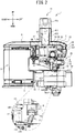
- the upper transport mechanism 31 is provided in the upper transport unit 30.
- the upper transport unit 30 is configured to be detachably mounted on a main body portion 33 of the bonding device 1.
- the main body portion 33 is a frame body that forms the head portion 5.
- the upper transport unit 30 is provided with a seat portion 61, an attachment portion 62, the upper transport mechanism 31, the upper detection portion 140 and the upper clamp mechanism 130.
- the seat portion 61 has a plate shape and extends horizontally.
- the attachment portion 62 is used to detachably attach the upper transport unit 30, which includes the upper transport mechanism 31, to the main body portion 33 of the bonding device 1.
- the attachment portion 62 extends upward from the rear right end of the seat portion 61, and bends to the left on the upper side.
- the attachment portion 62 has a right-angled triangular shape in a left side view, and has an inclined plane on the rear side.
- the upper surface of the attachment portion 62 extends horizontally.
- the attachment portion 62 has a unit position adjustment portion 65 that is configured to adjust the position of the upper transport unit 30 in the axial direction (the left-right direction) with respect to the bonding device 1.
- the unit position adjustment portion 65 has long holes 67 to 69 that extend in the left-right direction, and a guide portion 70.
- the long holes 67 to 69 have the same shape as each other, and penetrate in the front-rear direction.
- the upper transport unit 30 is fixed to the main body portion 33 of the bonding device 1, by tightening screws 57 to 59 inserted through the long holes 67 to 69 into screw holes provided in the main body portion 33 of the bonding device 1.
- the long holes 67 and 68 are arranged side by side in the left-right direction on an upper portion of the attachment portion 62.
- the long hole 67 is located to the right of the long hole 68.
- the long hole 69 is located below the long hole 67.
- the guide portion 70 has a groove shape and extends in the left-right direction.
- the guide portion 70 is provided between the long hole 69 and the long holes 67 and 68 in the up-down direction.
- the guide portion 70 is engaged with a convex portion 34 that is provided on the main body portion 33 of the bonding device 1.
- the convex portion 34 extends in the left-right direction in an inner rear portion of the head portion 5, and protrudes to the rear.
- the unit position adjustment portion 65 is configured to adjust the position of the upper transport unit 30 in the left-right direction with respect to the bonding device 1, by adjusting the position of the long holes 67 to 69 with respect to the screws 57 to 59.
- an operator loosens the screws 57 to 59 to an extent that inhibits the screws 57 to 59 from falling out from the long holes 67 to 69.
- the upper transport unit 30 can move to the left and the right.
- the operator After moving the upper transport unit 30 to a desired position in the left-right direction, the operator once again tightens the screws 57 to 59. By removing the screws 57 to 59, the operator can remove the upper transport unit 30 from the main body portion 33 of the bonding device 1.
- the upper transport mechanism 31 is provided with the upper transport roller 12, a support arm portion 16, an upper transport motor 71, a link mechanism 90 and an actuator 100.
- the upper transport roller 12 is configured to rotate around an upper roller shaft 84 that extends in the axial direction, and clamps, from above, the lower sheet 8 and the upper sheet 6 between the upper transport roller 12 and the lower transport roller 270.
- the axial direction of the upper roller shaft 84 is the left-right direction.
- the upper transport roller 12 is positioned to the rear of the nozzle 11.
- the upper transport roller 12 is configured to be moved by the actuator 100 to the press position and a standby position, integrally with a front end portion 16A of the support arm portion 16. As shown by the solid line in FIG.
- the press position is a position at which the upper transport roller 12 presses the upper sheet 6 and the lower sheet 8 between the upper transport roller 12 and the lower transport roller 270.
- the standby position is a position at which the upper transport roller 12 is above the press position.
- the support arm portion 16 extends in the front-rear direction, and rotatably supports the upper transport roller 12 at the front end portion 16A.
- the support arm portion 16 is configured to swing around a rear end portion 16B side.
- the support arm portion 16 has a pair of left and right plate portions 161 and 162.
- the upper transport motor 71 is configured to drive the upper transport roller 12.
- the upper transport motor 71 is provided on the support arm portion 16.
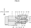
- an output shaft 711 of the upper transport motor 71 protrudes to the right, and is coupled to the upper roller shaft 84 via a coupling shaft 87, a coupling member 86, a first pulley 81, a second pulley 82 and a timing belt 83.
- the coupling shaft 87 extends in the left-right direction at the right of the output shaft 711.
- the coupling member 86 is a cylindrical member having a hole 88 that extends in the left-right direction.
- the output shaft 711 and the coupling shaft 87 are inserted through the hole 88, and thus the coupling member 86 couples the right end of the output shaft 711 and the left end of the coupling shaft 87.
- the coupling shaft 87 rotates integrally with the output shaft 711.
- the coupling shaft 87 is supported by the support arm portion 16 via bearings 89 and 94.
- the plate portions 161 and 162 of the support arm portion 16 have circular holes 163 and 164 that penetrate in the left-right direction.
- the bearings 89 and 94 are respectively fitted into the holes 163 and 164 and are thus supported by the plate portions 161 and 162.
- the coupling shaft 87 can rotate relative to the support arm portion 16 due to the bearings 89 and 94.
- the first pulley 81 is provided on the coupling shaft 87 between the bearings 89 and 94.
- the second pulley 82 is supported by the upper roller shaft 84 and is aligned with the upper transport roller 12 in the left-right direction.
- the timing belt 83 is stretched between the first pulley 81 and the second pulley 82.
- the first pulley 81, the second pulley 82 and the timing belt 83 are provided between the plate portions 161 and 162.
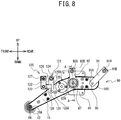
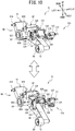
- the link mechanism 90 has a first link 91 and a second link 92.
- a lower end portion 91A of the first link 91 is rotatably supported by the rear end portion 16B of the support arm portion 16, and the first link 91 is configured to rotate around an upper end portion 91B.
- the first link 91 has an inverted U shape in a front view, and is provided with a main body portion 915, a concave portion 911, arm portions 912 and 913, and coupling shafts 914 and 95.
- the main body portion 915 is an upper portion of the first link 91.
- the concave portion 911 is a portion that is recessed upward from the lower end of the first link 91.
- the concave portion 911 is located between the arm portions 912 and 913 in the left-right direction.
- the arm portion 912 extends downward from a lower left portion of the main body portion 915.
- the arm portion 913 extends downward from a lower right portion of the main body portion 915.
- the support arm portion 16 is disposed in the concave portion 911 of the first link 91.
- the arm portion 912 is located to the left of the plate portion 161.
- the arm portion 913 is located to the right of the plate portion 162.
- the coupling shaft 95 extends in the left-right direction between the arm portion 912 and the arm portion 913.
- the coupling shaft 95 is inserted through holes of the plate portions 161 and 162.
- the first link 91 supports the support arm portion 16 from both sides of the support arm portion 16 in the left-right direction.
- the coupling shaft 914 has a rod shape and extends in the left-right direction.
- the coupling shaft 914 penetrates a hole in an upper portion of the main body portion 915.
- the coupling shaft 914 is supported by a concave portion 611 of the seat portion 61.
- the concave portion 611 is provided in a rear left portion of the seat portion 61, and is a portion that is recessed forward from the rear end portion of the seat portion 61.
- the seat portion 61 supports the first link 91 such that the first link 91 is configured to rotate around the coupling shaft 914.
- a lower end portion 92A of the second link 92 is rotatably supported by a section of the support arm portion 16 between the front end portion 16A and the rear end portion 16B of the support arm portion 16, and the second link 92 is configured to rotate around an upper end portion 92B of the second link 92.
- the second link 92 is provided on the upstream side in the transport direction with respect to the first link 91.
- the second link 92 has an inverted U shape in a front view, and is provided with a main body portion 927, a concave portion 921, arm portions 922 and 923, a coupling shaft 926 and the coupling shaft 87.
- the main body portion 927 is an upper portion of the second link 92.
- the concave portion 921 is a portion that is recessed upward from the lower end of the second link 92.
- the concave portion 921 is located between the arm portions 922 and 923 in the left-right direction.
- the arm portion 922 extends downward from a lower left portion of the main body portion 927.
- the arm portion 923 extends downward from a lower right portion of the main body portion 927.
- the support arm portion 16 is disposed in the concave portion 921 of the second link 92.
- the arm portion 922 is located to the left of the plate portion 161.
- the arm portion 923 is located to the right of the plate portion 162.
- the lower end portion of the arm portion 922 has a holding portion 924.
- the holding portion 924 has a cylindrical shape and has a hole 925 that extends in the left-right direction.
- the holding portion 924 holds the output shaft 711, the coupling shaft 87 and the coupling member 86 in the hole 925.
- the output shaft 711 of the upper transport motor 71 is coaxial with the coupling shaft 87 of the second link 92 and the support arm portion 16.
- the left end portion of the holding portion 924 is supported by a support seat 85 via a bearing 93.
- the support seat 85 is provided to the right of the upper transport motor 71, and is a cylindrical member having a hole 851 that extends in the left-right direction.
- the upper transport motor 71 is fixed to a left portion of the support seat 85 using screws 855 to 858.
- the bearing 93 is fitted into the hole 851.
- the support seat 85 holds the holding portion 924 of the second link 92 via the bearing 93.
- the upper transport motor 71 is provided on the support arm portion 16 via the support seat 85, the bearing 93, the second link 92, the coupling member 86, the coupling shaft 87 and the bearings 89 and 94.
- the arm portion 923 supports a bearing 96.
- the right end of the coupling shaft 87 is supported by the bearing 96.
- the coupling shaft 87 is inserted through the holding portion 924, the plate portions 161 and 162 and the arm portion 923.
- the coupling shaft 87 is positioned to the rear of the center of the support arm portion 16 in the front-rear direction.
- the second link 92 supports the support arm portion 16 from both the sides of the support arm portion 16 in the left-right direction.
- the coupling shaft 926 has a rod shape and extends in the left-right direction.
- the coupling shaft 926 penetrates a hole positioned in an upper portion of the main body portion 927. As shown in FIG.
- the coupling shaft 926 is supported by a hole portion 612 of the seat portion 61.
- the hole portion 612 is a portion that penetrates the seat portion 61 in the up-down direction, and has a substantially rectangular shape in a plan view.
- the hole portion 612 is provided to the front of the concave portion 611.
- the seat portion 61 supports the second link 92 such that the second link 92 is configured to rotate around the coupling shaft 926.
- the first link 91 and the second link 92 form a four-joint link mechanism together with the support arm portion 16.
- the coupling shaft 914 of the first link 91 and the coupling shaft 926 of the second link 92 are fixed ends.
- the coupling shaft 95 of the first link 91 and the support arm portion 16, and the coupling shaft 87 of the second link 92 and the support arm portion 16 are free ends.
- the actuator 100 is configured to move the front end portion 16A of the support arm portion 16 up and down, by transmitting power to the support arm portion 16 via a coupling link mechanism 120.
- the actuator 100 is an air cylinder that extends in parallel to the transport direction of the upper sheet 6.
- the actuator 100 is provided with connection ports 101 and 102, a piston, an output shaft 103 and a fixing portion 104.
- the connection ports 101 and 102 are connected to a compressor via pipes.
- a control portion (not shown in the drawings) of the bonding device 1 controls electromagnetic valves (not shown in the drawings) provided in the pipes, and thus controls the driving of the actuator 100.
- the piston is provided inside the actuator 100 and is coupled to the output shaft 103.
- the output shaft 103 is directed forward.
- the output shaft 103 moves to the front and the rear due to air that is introduced and expelled via the connection ports 101 and 102.
- the fixing portion 104 is a portion that extends upward, and is provided on a rear portion of the actuator 100. The fixing portion 104 is used to fix the actuator 100 to the lower surface of the seat portion 61.
- the coupling link mechanism 120 is coupled to the output shaft 103 of the actuator 100 and to the support arm portion 16.
- the coupling link mechanism 120 has third links 125, a fourth link 122, a fifth link 126, coupling shafts 123, 127, 124 and 128, and a coupling portion 129.
- the coupling shafts 123, 127, 124 and 128 each have a rod shape that extends in the left-right direction.
- the third links 125 are a pair of left and right plates that extend in the up-down direction from both the sides of the support arm portion 16 in the left-right direction.
- a lower end portion 125A of each of the third links 125 is rotatably supported by the support arm portion 16.
- each of the third links 125 is provided with the coupling shaft 128 that protrudes toward the support arm portion 16.
- the coupling shafts 128 are respectively inserted into holes that penetrate the plate portions 161 and 162 of the support arm portion 16 in the left-right direction.
- An upper end portion 125B of each of the third links 125 is coupled to the rear end of the fifth link 126 by the coupling shaft 124.
- the fifth link 126 is a plate-shaped member and is positioned between the pair of left and right third links 125.
- the front end portion of the fifth link 126 is fixed to the coupling shaft 127, and is coupled to the upper end of the fourth link 122 by the coupling shaft 127.
- the coupling shaft 127 is rotatably supported by the seat portion 61.
- the fourth link 122 is located to the right of a left link portion 121.
- the left link portion 121 is a link including the third links 125, the fifth link 126 and the coupling shaft 124.
- the fourth link 122 is a rectangular plate-shaped member, and the lower end portion of the fourth link 122 has a concave portion that is recessed upward.
- the lower end portion of the fourth link 122 is coupled to the front end of the coupling portion 129 by the coupling shaft 123.
- the coupling portion 129 is disposed in the concave portion of the fourth link 122.
- the coupling portion 129 extends in the front-rear direction and is coupled to the output shaft 103 of the actuator 100.
- the bonding device 1 adjusts the position, in the left-right direction, of the left end portion of the upper sheet 6 using the upper clamp mechanism 130.
- the upper clamp mechanism 130 is provided with a fixing base 131, a motor 132, a coupling mechanism 133, an arm portion 134 and a roller 135.
- the fixing base 131 is a plate-shaped member.
- the fixing base 131 is used to fix the upper clamp mechanism 130 to the right end of the seat portion 61.
- the motor 132 is a stepping motor that is configured to rotate forward and backward. An output shaft of the motor 132 is directed forward.
- the coupling mechanism 133 is coupled to the output shaft of the motor 132 and the arm portion 134.
- the arm portion 134 extends leftward and downward from a coupling portion with the coupling mechanism 133, and rotatably supports the roller 135 at the left end portion of the arm portion 134.
- the arm portion 134 is internally provided with a transmission mechanism that is coupled to the output shaft of the motor 132 and a shaft 136 of the roller 135.
- the power of the motor 132 is transmitted to the roller 135 via the transmission mechanism.
- the upper detection portion 140 is configured to detect whether or not the left end portion of the upper sheet 6 is located above a specified position.
- the specified position is a predetermined position in the front-rear direction that is between the discharge port 112 of the nozzle 11 in the facing position and the roller 135, and is a position to the left of the roller 135.
- the upper detection portion 140 is a well-known optical sensor and is provided with a light emitting portion and a light receiving portion. The light emitting portion and the light receiving portion are provided at same height positions.
- the light emitting portion is configured to emit light toward the specified position that is below the light emitting portion.
- the light receiving portion is configured to receive the light emitted by the light emitting portion.
- the upper sheet 6 When the upper sheet 6 is not located at the specified position, the light emitted by the light emitting portion is reflected by a reflection portion provided on the upper surface of a support base 305 to be described later, and the light receiving portion can receive the light emitted by the light emitting portion.
- the upper sheet 6 blocks the light emitted by the light emitting portion, and the light receiving portion cannot receive the light emitted by the light emitting portion. Therefore, the upper detection portion 140 can detect whether or not the left end portion of the upper sheet 6 is located above the specified position.
- the upper detection portion 140 is fixed to the seat portion 61 via a support member 141 and a fixing member 145.
- the support member 141 has a detection portion position adjustment portion 142 and is configured to adjust the position of the upper detection portion 140 in the left-right direction with respect to the attachment portion 62.
- the support member 141 is a plate-shaped member that extends in the left-right direction.
- the support member 141 supports the upper detection portion 140 such that the upper detection portion 140 is inserted through a hole, which is provided in the left end portion of the support member 141 and penetrates in the up-down direction, in a posture in which the light emitting portion and the light receiving portion are directed downward.
- the support member 141 is provided with the detection portion position adjustment portion 142 to the right of the upper detection portion 140.
- the detection portion position adjustment portion 142 is a long hole that extends in the left-right direction and that penetrates in the front-rear direction.
- the fixing member 145 is a plate-shaped member that is long in the up-down direction. The position of the fixing member 145 in the left-right direction is to the right of the upper detection portion 140 and the upper transport roller 12.
- the fixing member 145 has a shape such that it curves forward as it extends downward.
- the upper end of the fixing member 145 is fixed to the front end of the seat portion 61 using a pair of left and right screws 146 and 147.
- the lower end portion of the fixing member 145 has a pair of left and right screw holes. Two screws 143 and 144 that are inserted through the detection portion position adjustment portion 142 are tightened into the pair of left and right screw holes, respectively.
- the support member 141 is fixed to the fixing member 145.
- the operator When adjusting the position of the upper detection portion 140 in the left-right direction with respect to the attachment portion 62, the operator loosens the screws 143 and 144 to an extent that inhibits the screws 143 and 144 from falling out from the detection portion position adjustment portion 142.
- the support member 141 is configured to move to the left and the right with respect to the attachment portion 62. After moving the support member 141 to a desired position in the left-right direction, the operator once again tightens the screws 143 and 144.
- the upper support mechanism 310 is provided on the base 7 and is provided with the support base 305.
- the support base 305 has a plate shape that extends horizontally, and supports the upper sheet 6.
- the support base 305 can be displaced in the left-right direction.
- the lower detection mechanism 530 is configured to detect whether or not the right end portion of the lower sheet 8 is located at the specified position.
- the lower detection mechanism 530 is provided with a fixing member 535 and a lower detection portion 532.
- the lower detection portion 532 is a well-known optical sensor that is fixed to the fixing member 535, and is provided with a light emitting portion and a light receiving portion. The light emitting portion and the light receiving portion are provided at same height positions.
- the light emitting portion is configured to emit light toward an inside area of a through hole that is provided in the support portion 52 and that penetrates in the up-down direction.
- the light emitted by the light emitting portion is reflected by a reflection portion provided on the lower surface of the support base 305, and the light receiving portion is configured to receive the light emitted by the light emitting portion.
- the lower sheet 8 blocks the light emitted by the light emitting portion, and the light receiving portion cannot receive the light emitted by the light emitting portion. Therefore, the lower detection portion 532 can detect whether or not the right end portion of the lower sheet 8 is located at the specified position above the through hole.
- the lower clamp mechanism 500 is configured to move the right end portion of the lower sheet 8 to the left and the right.
- the lower clamp mechanism 500 is provided with a motor 505, an arm portion, a coupling mechanism and a roller 501.
- the motor 505 is a motor that is configured to rotate forward and backward.
- An output shaft of the motor 505 is directed rearward.
- the arm portion extends rightward and upward from the rear of the motor 505, and is internally provided with a transmission mechanism that is coupled to the output shaft of the motor 505 and a shaft of the roller 501.
- the power of the motor 505 is transmitted to the roller 501 via the transmission mechanism.
- the motor 505 is configured to drive the roller 501.
- each of the third links 125 extends upward from the lower end portion 125A to the upper end portion 125B.
- the second link 92 extends substantially downward from the upper end portion 92B to the lower end portion 92A
- the first link 91 extends toward the upstream side in the transport direction and downward from the upper end portion 91B, which is coupled to the seat portion 61 to the lower end portion 91A, which is coupled to the support arm portion 16.
- the direction from the fixed end toward the free end of the second link 92 need not necessarily strictly be the downward direction.
- the direction from the fixed end to the free end of the second link 92 is closer to the vertical than when the upper transport roller 12 is in the standby position.
- the direction in which each of the third links 125 extends from the lower end portion 125A to the upper end portion 125B need not necessarily strictly be the up-down direction.
- the actuator 100 moves the output shaft 103 to the rear.
- the coupling shaft 127 of the coupling link mechanism 120 that is coupled to the output shaft 103 via the coupling portion 129 rotates in the clockwise direction in a left side view, and the coupling shafts 123, 124 and 128 respectively move rearward, upward, and rearward and upward.
- the coupling shaft 128 moves rearward and upward, the coupling shafts 95 and 87, which are the free ends of the link mechanism 90, respectively move rearward and downward, and rearward and upward, and the front end portion 16A of the support arm portion 16 moves upward.
- a bonding operation of the bonding device 1 will be explained.
- the upper transport roller 12 is in the press position, and the right end portion of the lower sheet 8 and the left end portion of the upper sheet 6 are overlapped with each other at a pressure bonding point of the upper transport roller 12 and the lower transport roller 270.
- the bonding device 1 drives the upper transport motor 71 and the lower transport motor 262 in synchronization with each other.
- the upper transport roller 12 rotates in the clockwise direction in a left side view.
- the lower transport roller 270 rotates in the counterclockwise direction in a left side view.
- the lower sheet 8 and the upper sheet 6 move from the upstream side to the downstream side in the transport direction.
- the bonding device 1 drives the upper clamp mechanism 130 and adjusts the position of the left end portion of the upper sheet 6 in the left-right direction.
- the bonding device 1 drives the lower clamp mechanism 500 and adjusts the position of the right end portion of the lower sheet 8 in the left-right direction.
- the bonding device 1 drives the pump motor 114 of the supply mechanism 45.
- the gear pump 46 of the supply mechanism 45 is driven, sucks up an appropriate amount of adhesive from the cartridge mounted in the mounting portion 41, and supplies the adhesive to the flow path 37 inside the lever 9.
- the adhesive flows from the flow path 37 to the flow path 113 inside the nozzle 11.
- the adhesive is discharged from the discharge port 112 of the nozzle 11.
- the bonding device 1 clamps a bonding section of the lower sheet 8 and the upper sheet 6 between the upper transport roller 12 and the lower transport roller 270, and transports the lower sheet 8 and the upper sheet 6 from the front to the rear while bonding them together by pressing a bonding surface to which the adhesive has been applied.
- the bonding device 1, the discharge port 112, the nozzle 11, the supply mechanism 45 and the transport mechanism 43 are respectively examples of a bonding device, a discharge port, a nozzle, a supply mechanism and a transport mechanism of the present invention.
- the transport shaft 268, the lower transport roller 270, the upper roller shaft 84, the upper transport roller 12, the lower transport motor 262, the support arm portion 16, the upper transport motor 71 and the actuator 100 are respectively examples of a lower roller shaft, a lower transport roller, an upper roller shaft, an upper transport roller, a lower transport motor, a support arm portion, an upper transport motor and an actuator of the present invention.
- the first link 91, the second link 92, the link mechanism 90, the coupling shaft 87, the third links 125 and the coupling link mechanism 120 are respectively examples of a first link, a second link, a link mechanism, a coupling shaft, a third link and a coupling link mechanism of the present invention.
- the upper transport unit 30, the main body portion 33 of the bonding device 1, the attachment portion 62, the unit position adjustment portion 65, the upper detection portion 140 and the detection portion position adjustment portion 142 are respectively examples of an upper transport unit, a main body portion of the bonding device, an attachment portion, a unit position adjustment portion, a detection portion and a detection portion position adjustment portion of the present invention.
- a known bonding device swings a support arm portion around a shaft that is provided in the support arm portion, and thus causes an upper transport roller provided on one end of the support arm portion to move upward.
- the upper transport roller moves upward, the upper transport roller moves in an arc shape around the shaft provided in the support arm portion, and therefore, also moves in the forward direction.
- the coupling shaft 87 that supports the lower end portion 92A of the second link 92 is moved rearward by the link mechanism 90, and therefore, the front end portion 16A of the support arm portion 16 is unlikely to move forward.
- the bonding device 1 can reduce the amount of movement of the upper transport roller 12 toward the upstream side in the transport direction when the upper transport roller 12 moves upward, in comparison to the related art.
- the bonding device 1 can increase the amount of upward movement of the upper transport roller 12 in comparison to the related art. Therefore, the bonding device 1 can enlarge a working space below the support arm portion 16 in comparison to the related art, and can improve workability when arranging the upper sheet 6 and the lower sheet 8 on the bonding device 1.
- the output shaft 711 of the upper transport motor 71 of the bonding device 1 is coaxial with the coupling shaft 87 of the second link 92 and the support arm portion 16.
- the bonding device 1 can reduce an influence of a weight of the upper transport motor 71 when the upper transport roller 12 moves upward or downward.
- the front end portion 16A of the support arm portion 16 does not rapidly move downward due to the weight of the upper transport motor 71.
- the safety of the bonding device 1 is higher than that of a device in which the support arm portion 16 supports the upper transport motor 71 and the output shaft 711 of the upper transport motor 71 is not coaxial with the coupling shaft 87 of the second link 92 and the support arm portion 16.
- the upper transport motor 71 of the bonding device 1 is supported by the support arm portion 16. In comparison to a device in which the upper transport motor 71 is supported by a portion other than the support arm portion 16, the bonding device 1 can simplify the structure that transmits the power of the upper transport motor 71 to the upper transport roller 12.
- the bonding device 1 when the upper transport roller 12 moves upward or downward, a positional relationship between a rotation position of the output shaft 711 of the upper transport motor 71 and a rotation position of the upper transport roller 12 is unlikely to change. Therefore, when the upper transport roller 12 moves upward or downward, the bonding device 1 can inhibit the upper transport roller 12 from rotating due to a change in the aforementioned positional relationship.
- the support arm portion 16 supports the coupling shaft 87 via the bearings 89 and 94.
- the bonding device 1 couples the support seat 85 and the second link 92 via the bearing 93.
- the second link 92 supports the right end of the coupling shaft 87 via the bearing 96. Therefore, with a relatively simple structure, the bonding device 1 can downsize the structure in which the support arm portion 16 supports the upper transport motor 71 and the structure in which the output shaft 711 of the upper transport motor 71 is coaxial with the coupling shaft 87 of the second link 92 and the support arm portion 16.
- the actuator 100 of the bonding device 1 is the air cylinder that extends in parallel to the transport direction of the upper sheet 6.
- the bonding device 1 has a smaller structure in the up-down direction, in comparison to when an actuator extending in the up-down direction is provided.
- the bonding device 1 can expand the working space below the support arm portion 16 in comparison to the related art, and can improve the workability when arranging the upper sheet 6 and the lower sheet 8 on the bonding device 1.
- the bonding device 1 includes the third links 125 that are rotatably supported by the support arm portion 16, and further includes the coupling link mechanism 120 that is coupled to the output shaft 103 of the actuator 100 and to the support arm portion 16.
- each of the third links 125 extends upward from the lower end portion 125A to the upper end portion 125B. In other words, each of the third links 125 extends in the up-down direction.
- the bonding device 1 can more efficiently transmit the power of the actuator 100 in the downward direction, in comparison to when each of the third links 125 does not extend in the up-down direction.
- the bonding device 1 is provided with the attachment portion 62 that is used to detachably attach the upper transport unit 30 including the upper transport motor 71 and the support arm portion 16 to the main body portion 33 of the bonding device 1.
- the upper transport unit 30 can be attached to and detached from the main body portion 33 of the bonding device 1. Therefore, in the bonding device 1, a maintenance operation can be performed by detaching the upper transport unit 30, and the maintenance operation of the upper transport unit 30 can be easily performed.
- the attachment portion 62 of the bonding device 1 has the unit position adjustment portion 65 that can adjust the position of the upper transport unit 30 in the left-right direction with respect to the bonding device 1.
- the bonding device 1 can adjust the position of the upper transport roller 12 in the left-right direction with respect to the nozzle 11.
- the plurality of types of nozzles 11 can be selectively mounted on the bonding device 1.
- the bonding device 1 can adjust the position of the upper transport roller 12 in the left-right direction, in accordance with the size and shape of the nozzle 11 mounted on the mounting portion 10 or an application position of the adhesive onto the lower sheet 8.
- the upper detection portion 140 and the detection portion position adjustment portion 142 are provided in the upper transport unit 30.
- the upper detection portion 140 is positioned to the front of the nozzle 11 and can detect the position of the upper sheet 6.
- the detection portion position adjustment portion 142 can adjust the position of the upper detection portion 140 in the left-right direction with respect to the attachment portion 62.
- the bonding device 1 can adjust the position of the upper detection portion 140 in the left-right direction with respect to the nozzle 11.
- the bonding device 1 can adjust the position of the upper sheet 6 in the left-right direction in accordance with the size and shape of the nozzle 11 mounted on the mounting portion 10.
- the axial direction of the upper transport roller of the bonding device, and the transport direction of the lower sheet 8 and the upper sheet 6 may be changed as appropriate.
- the upper transport unit need not necessarily be detachable with respect to the main body portion of the bonding device.
- the upper transport unit need not necessarily be provided with the unit position adjustment portion and need not necessarily be movable in the axial direction of the upper transport roller with respect to the main body portion of the bonding device.
- the upper clamp mechanism, the upper detection portion and the detection portion position adjustment portion may be omitted from the upper transport unit, as appropriate.
- the nozzle 11 need not necessarily be detachable with respect to the mounting portion 10, and the size, the shape and the like of the nozzle 11 may be changed as appropriate.
- the structure of each of the unit position adjustment portion 65 and the detection portion position adjustment portion 142 may be changed as appropriate.
- the attachment portion 62 need not necessarily include the unit position adjustment portion 65.
- the guide portion 70 may be omitted from the unit position adjustment portion 65.
- the number, the shape and the arrangement of the long holes 67 to 69 of the unit position adjustment portion 65 may be changed as appropriate.
- the upper detection portion 140 may be a well-known sensor, such as an image sensor or the like, other than the optical sensor.
- the structural members of the lower transport mechanism may be changed as appropriate.
- the upper transport mechanism is provided with the upper transport motor, the upper transport roller, the link mechanism and the actuator, the other structural members of the upper transport mechanism may be changed as appropriate.
- the output shaft of the upper transport motor need not necessarily be coaxial with the coupling shaft of the second link and the support arm portion.
- the upper transport motor need not necessarily be supported by the support arm portion.
- the upper transport motor may be provided in the main body portion of the bonding device, a pulley may be provided on the output shaft of the upper transport motor, and a timing belt may be stretched between the pulley and the first pulley 81.
- the upper transport motor may be supported by the second link.
- the actuator may be a solenoid, or may be an air cylinder or a solenoid that extends in a direction orthogonal to the transport direction of the upper sheet.
- the first link and the second link may be coupled to only one end side of the support arm portion in the left-right direction.
- the output shaft of the actuator may be directly coupled to the support arm portion.
- the mechanism that transmits the power of the actuator to the support arm portion may be changed as appropriate.
- the bonding device need not necessarily be provided with the coupling link mechanism.
- the third links of the coupling link mechanism may extend in a direction that intersects with the up-down direction.
Landscapes
- Engineering & Computer Science (AREA)
- Mechanical Engineering (AREA)
- Chemical & Material Sciences (AREA)
- Organic Chemistry (AREA)
- Folding Of Thin Sheet-Like Materials, Special Discharging Devices, And Others (AREA)
- Adhesives Or Adhesive Processes (AREA)
Abstract
A bonding device (1) includes a transport mechanism (43) including an upper transport roller (12) and an upper transport motor (71). The upper transport roller is moved by an actuator to a press position and to a standby position. A link mechanism (90) has a first link (91) and a second link (92). When the upper transport roller is in a press position, the second link extends downward to one end portion (92A) from another end portion (92B) of the second link, and the first link extends toward an upstream side in a transport direction and downward to one end portion (91A) from another end portion (91B) of the first link. When the upper transport roller is in a standby position, the second link extends toward a downstream side in the transport direction and downward from the other end portion of the second link to the one end portion.
Description
- The present invention relates to a bonding device and an upper transport unit.
- A bonding device is known that bonds two sheets together via an adhesive. A bonding device disclosed in Japanese Laid-Open Patent Publication No.
2016-190913 - It is preferable that the press position be in the vicinity of a downstream side of the nozzle that is in the facing position in a transport direction of the upper sheet. In the above-described bonding device, the upper arm swings around the coupling portion with the upper arm base. Therefore, when the upper arm moves upward, the upper transport roller moves forward and upward from the press position. Therefore, if an interval between the nozzle in the facing position and the upper transport roller is narrow, the nozzle and the upper transport roller interferer with each other when the upper transport roller moves upward. If priority is given to narrowing the interval between the nozzle and the upper transport roller and an upward movement amount of the upper roller is reduced, workability deteriorates when the upper sheet and the lower sheet are arranged at a predetermined position.
- It is an object of the present invention to provide a bonding device and an upper transport unit that have an improved ratio of a movement amount of the upper transport roller in a transport direction of an upper sheet with respect to a movement amount of the upper transport roller in an up-down direction.
- A bonding device according to the first aspect of the present invention includes a nozzle, a supply mechanism, and a transport mechanism. The nozzle is provided between a lower sheet and an upper sheet overlapped on the lower sheet from above. The nozzle has a discharge port configured to discharge an adhesive toward the lower sheet. The supply mechanism is configured to supply the adhesive to the nozzle. The transport mechanism is configured to transport the lower sheet to which the adhesive has been applied and the upper sheet. The transport mechanism includes a lower transport roller, an upper transport roller, a lower transport motor, a support arm portion, and an upper transport motor. The lower transport roller is configured to rotate around a lower roller shaft on a downstream side in a transport direction of the lower sheet and the upper sheet with respect to the nozzle. The lower transport roller is configured to come into contact with the lower sheet from below. The lower roller shaft extends in an axial direction orthogonal to the transport direction and an up-down direction. The upper transport roller is configured to rotate around an upper roller shaft extending in the axial direction. The upper transport roller is configured to clamp, from above, the lower sheet and the upper sheet between the upper transport roller and the lower transport roller. The lower transport motor is configured to drive the lower transport roller. The support arm portion is configured to rotatably support the upper transport roller at one end portion of the support arm portion. The support arm portion is configured to swing around another end portion side of the support arm portion. The upper transport motor is configured to drive the upper transport roller. The upper transport roller is moved by an actuator to a press position, at which the upper transport roller presses the upper sheet and the lower sheet between the upper transport roller and the lower transport roller, and to a standby position, at which the upper transport roller is positioned above the press position. The bonding device includes a link mechanism and a seat portion. The link mechanism has a first link and a second link provided on an upstream side of the first link in the transport direction. The seat portion supports the link mechanism. One end portion of the first link is rotatably supported by the other end portion of the support arm portion. Another end portion of the first link is rotatably supported by the seat portion. The first link is configured to rotate around the other end portion of the first link. One end portion of the second link is rotatably supported by a section of the support arm portion between the one end portion of the support arm portion and the other end portion of the support arm portion. Another end portion of the second link is rotatably supported by the seat portion. The second link is configured to rotate around the other end portion of the second link. When the upper transport roller is in the press position, the second link extends downward from the other end portion of the second link to the one end portion of the second link, and the first link extends toward the upstream side in the transport direction and downward from the other end portion of the first link to the one end portion of the first link. When the upper transport roller is in the standby position, the second link extends toward the downstream side in the transport direction and downward from the other end portion of the second link to the one end portion of the second link.
- In the bonding device of the according to the first aspect, when the upper transport roller moves upward, a section that supports the one end portion of the second link is moved a upstream side in the transport direction by the link mechanism, and therefore, the one end portion of the support arm portion is unlikely to move toward the upstream side in the transport direction. Thus, the bonding device can reduce the amount of movement of the upper transport roller toward the upstream side in the transport direction when the upper transport roller moves upward, in comparison to the related art. In comparison to the related art, when the upper transport roller moves upward, the upper transport roller is less likely to interfere with another member disposed on the upstream side in the transport direction, and the bonding device can increase the amount of upward movement of the upper transport roller in comparison to the related art. The bonding device can enlarge a working space below the support arm portion in comparison to the related art, and can improve workability when arranging the upper sheet and the lower sheet on the bonding device.
- In the bonding device according to the first aspect, an output shaft of the upper transport motor may be coaxial with a coupling shaft of the second link and the support arm portion. In comparison to a device in which the output shaft of the upper transport motor is not coaxial with the coupling shaft of the second link and the support arm portion, the bonding device can reduce an influence of a weight of the upper transport motor, when the upper transport roller moves upward or downward. In the bonding device, when the power is not transmitted from the actuator to the support arm portion in a state in which the upper transport roller is in the standby position, the one end portion of the support arm portion does not rapidly move downward due to the weight of the upper transport motor. Thus, the safety of the bonding device is higher than that of a device in which the support arm portion supports the upper transport motor and the output shaft of the upper transport motor is not coaxial with the coupling shaft of the second link and the support arm portion.
- In the bonding device according to the first aspect, the upper transport motor may be supported by the support arm portion. In comparison to a device in which the upper transport motor is supported by a portion other than the support arm portion, the bonding device can simplify the structure that transmits the power of the upper transport motor to the upper transport roller. In the bonding device, when the upper transport roller moves upward or downward, a positional relationship between a rotation position of the output shaft of the upper transport motor and a rotation position of the upper transport roller is unlikely to change. Therefore, when the upper transport roller moves upward or downward, the bonding device can inhibit the upper transport roller from rotating due to a change in the aforementioned positional relationship.
- In the bonding device according to the first aspect, the actuator may be an air cylinder extending in parallel to the transport direction. The bonding device has a smaller structure in the up-down direction, in comparison to when an actuator extending in the up-down direction is provided. The bonding device can expand the working space below the support arm portion in comparison to the related art, and can improve the workability when arranging the upper sheet and the lower sheet on the bonding device.
- The bonding device according to the first aspect may further include a coupling link mechanism coupled to an output shaft of the air cylinder and to the support arm portion. The coupling link mechanism may have a third link. One end portion of the third link may be rotatably supported by the support arm portion. When the upper transport roller is in the press position, the third link may extend upward from one end portion of the third link to another end portion the third link. When the upper transport roller is in the press position, the bonding device can efficiently transmit the power of the actuator in the downward direction.
- The bonding device according to the first aspect may further include an attachment portion configured to detachably attach an upper transport unit including the upper transport motor and the support arm portion to a main body portion of the bonding device. The attachment portion is connected to the seat portion. In the bonding device, the attachment portion can be attached to and detached from the main body portion of the bonding device. Therefore, in the bonding device, a maintenance operation can be performed by only detaching the upper transport unit.
- In the bonding device according to the first aspect, the attachment portion has a unit position adjustment portion configured to adjust a position of the upper transport unit in the axial direction with respect to the bonding device. The bonding device can adjust the position of the upper transport roller in the left-right direction with respect to the nozzle.
- The bonding device according to the first aspect may further include a detection portion and a detection portion position adjustment portion. The detection portion is configured to detect a position of the upper sheet in the axial direction. The detection portion is fixed to the seat portion. The detection portion is positioned on the upstream side of the nozzle in the transport direction when the upper transport unit is mounted on the main body portion of the bonding device. The detection portion position adjustment portion is configured to adjust a position of the detection portion in the axial direction with respect to the attachment portion. The bonding device can adjust the position of the detection portion in the axial direction with respect to the nozzle.
- An upper transport unit according to the second aspect of the present invention includes an upper transport roller, an upper transport motor, and a support arm portion. The upper transport roller is configured to rotate around an upper roller shaft extending in an axial direction. The upper transport motor is configured to drive the upper transport roller. The support arm portion is configured to rotatably support the upper transport roller at one end portion of the support arm portion. The support arm portion is configured to swing around another end portion side of the support arm portion. The upper transport roller is movable by an actuator between a lower position and an upper position that is above the lower position. The bonding device is configured to bond a lower sheet and an upper sheet using an adhesive the bonding device is configured to transport the lower sheet and the upper sheet in a transport direction when the upper transport roller is in the lower position. The upper transport unit includes a link mechanism having a first link and a second link provided on an upstream side of the first link in the transport direction. The upper transport unit is supported by a seat portion. One end portion of the first link is rotatably supported by the other end portion of the support arm portion. Another end portion of the first link is rotatably supported by the seat portion. The first link is configured to rotate around the other end portion of the first link. One end portion of the second link is rotatably supported by a section of the support arm portion between the one end portion of the support arm portion and the other end portion of the support arm portion. Another end portion of the second link is rotatably supported by the seat portion. The second link is configured to rotate around the other end portion of the second link. When the upper transport roller is in the lower position, the second link extends downward from the other end portion of the second link to the one end portion of the second link, and the first link extends toward the upstream side in the transport direction and downward from the other end portion of the first link to the one end portion of the first link. When the upper transport roller is in the upper position, the second link extends toward the downstream side in the transport direction and downward from the other end portion of the second link to the one end portion of the second link.
- In the upper transport unit according to the second aspect, when the upper transport unit is mount on the bonding device and the upper transport roller moves upward, a section that supports the one end portion of the second link is moved a upstream side in the transport direction by the link mechanism, and therefore, the one end portion of the support arm portion is unlikely to move toward the upstream side in the transport direction. Thus, the upper transport unit can reduce the amount of movement of the upper transport roller toward the upstream side in the transport direction when the upper transport roller moves upward, in comparison to the related art. In comparison to the related art, when the upper transport roller moves upward, the upper transport roller is less likely to interfere with another member disposed on the upstream side in the transport direction, and the upper transport unit can increase the amount of upward movement of the upper transport roller in comparison to the related art. The upper transport unit can enlarge a working space below the support arm portion in comparison to the related art, and can improve workability when arranging the upper sheet and the lower sheet on the bonding device.
- Embodiments will be described below in detail with reference to the accompanying drawings in which:
-
FIG. 1 is a perspective view of abonding device 1; -
FIG. 2 is a back view of thebonding device 1; -
FIG. 3 is a left side view of thebonding device 1; -
FIG. 4 is a perspective view of an internal configuration of thebonding device 1; -
FIG. 5 is a perspective view of anupper transport unit 30 when anupper transport roller 12 is in a press position; -
FIG. 6 is a left side view of theupper transport unit 30 when theupper transport roller 12 is in the press position; -
FIG. 7 is an exploded perspective view of anupper transport mechanism 31; -
FIG. 8 is a right side view of theupper transport mechanism 31 excluding anactuator 100 when theupper transport roller 12 is in the press position; -
FIG. 9 is a cross-sectional view taken along a line A-A shown inFIG. 8 ; -
FIG. 10 is a perspective view of theupper transport mechanism 31 excluding anupper transport motor 71 and asupport seat 85 when theupper transport roller 12 is in a standby position (an upper diagram) and when theupper transport roller 12 is in the press position (a lower diagram); -
FIG. 11 is a right side view of theupper transport mechanism 31 excluding theupper transport motor 71 and thesupport seat 85 when theupper transport roller 12 is in the standby position (an upper diagram) and when theupper transport roller 12 is in the press position (a lower diagram); and -
FIG. 12 is a left side view of theupper transport mechanism 31 excluding theupper transport motor 71 and thesupport seat 85 when theupper transport roller 12 is in the standby position (an upper diagram) and when theupper transport roller 12 is in the press position (a lower diagram). - An embodiment of the present invention will be explained. In the following explanation, left and right directions, front and rear directions, and up and down directions as indicated by arrows in the drawings are used. A
bonding device 1 bonds two sheets using an adhesive. The two sheets are alower sheet 8 and anupper sheet 6. Theupper sheet 6 is overlapped on thelower sheet 8 from above. Thelower sheet 8 and theupper sheet 6 are flexible cloths, for example. Thebonding device 1 bonds the right end portion of thelower sheet 8 and the left end portion of theupper sheet 6, via the adhesive. Thelower sheet 8 and theupper sheet 6 are shown inFIG. 3 only. - The configuration of the
bonding device 1 will be explained with reference toFIG. 1 to FIG. 12 . As shown inFIG. 1 to FIG. 4 , thebonding device 1 is provided with aseat portion 2, apillar 3, anarm portion 4, ahead portion 5, abase 7, a mountingportion 41, anozzle 11, asupply mechanism 45, atransport mechanism 43, anupper detection portion 140, anupper clamp mechanism 130, anupper support mechanism 310, alower detection mechanism 530 and alower clamp mechanism 500. Theseat portion 2 has a cuboid shape and is fixed to a work bench. Thepillar 3 has a columnar shape and extends upward from the upper surface of theseat portion 2. Thearm portion 4 extends to the left from the upper end portion of thepillar 3. Thehead portion 5 protrudes to the left from the left end portion of thearm portion 4. Thebase 7 extends in the left-right direction at the left of theseat portion 2. Thebase 7 is supported by a rectangular plate-shaped fixingportion 32 that is fixed to the left surface of theseat portion 2. Asupport portion 52 is fixed to the upper end of thebase 7. Thesupport portion 52 extends in the left-right direction and the front-rear direction. A left portion of thesupport portion 52 has a substantially rectangular shape in a plan view, and supports thelower sheet 8 from below. Thesupport portion 52 faces thehead portion 5. - The mounting
portion 41 is provided at a substantially central portion of thehead portion 5, and a cartridge is detachably mounted in the mountingportion 41. The cartridge stores a hot-melt adhesive. The mountingportion 41 is provided with acover 411, ahousing portion 412, alid 413 and a heater. Thecover 411 has a substantially cuboid box shape and extends upward from the upper surface of thehead portion 5. Thecover 411 is only partially shown inFIG. 1 andFIG. 2 , and thecover 411 is omitted inFIG. 4 . Thecover 411 opens in the up-down direction. Thehousing portion 412 is provided inside thecover 411. Thehousing portion 412 has a substantially cuboid box shape and extends from the interior of thehead portion 5 to the upper end of thecover 411. Thehousing portion 412 is open upward. The cartridge is housed inside thehousing portion 412. The adhesive liquefies at a predetermined temperature and solidifies at a temperature lower than the predetermined temperature. Thelid 413 covers thehousing portion 412 from above. The heater is provided in thehousing portion 412 and heats the adhesive. The adhesive is melted and liquefied by being heated. - The
nozzle 11 is provided between thelower sheet 8 and theupper sheet 6 that is overlapped on thelower sheet 8 from above. Thenozzle 11 has adischarge port 112 that discharges the adhesive toward thelower sheet 8. As shown inFIG. 2 , thenozzle 11 is provided below thehead portion 5, and has a rectangular shape that extends in the left-right direction. Thenozzle 11 is provided with thedischarge port 112 and aflow path 113. Thedischarge port 112 is provided in the lower surface of thenozzle 11, and has a plurality of circular holes that are aligned at substantially equal intervals in the left-right direction. Theflow path 113 extends in the left-right direction. Thenozzle 11 discharges the adhesive in theflow path 113 from thedischarge port 112 onto thelower sheet 8. - A
swing mechanism 22 is provided with amotor 221 and alever 9, and is configured to swing thelever 9 around an axis line that extends in the left-right direction. Themotor 221 is a pulse motor that is provided in thehead portion 5. An output shaft of themotor 221 is directed in the front-rear direction. Thelever 9 is coupled with the output shaft of themotor 221 via a coupling mechanism, and has an arm shape that extends downward from the lower end of thehead portion 5. Thenozzle 11 is detachably mounted on the lower end of thelever 9. As shown inFIG. 3 , using the power of themotor 221, thelever 9 can displace thenozzle 11 between a facing position shown by a solid line and a separated position shown by a two-dot chain line. When thenozzle 11 is in the facing position, thedischarge port 112 is directed downward and faces thelower sheet 8 from above. The separated position is a position on the counterclockwise side in a left side view around the axis line that extends in the left-right direction, with respect to the facing position. When thenozzle 11 is in the separated position, thedischarge port 112 is directed forward and downward. As shown inFIG. 2 , thelever 9 is internally provided with aflow path 37 and a heater. The lower end portion of thelever 9 is a mountingportion 10. Thenozzle 11 protrudes downward from the mountingportion 10 and further protrudes to the right. Thenozzle 11 is fixed to the mountingportion 10 using screws. Theflow path 113 of thenozzle 11 is communicated with theflow path 37. The heater of thelever 9 heats the adhesive flowing through theflow path 37. A plurality of types of thenozzles 11, whose sizes and shapes are different from each other, can be selectively mounted on the mountingportion 10. - As shown in
FIG. 4 , thesupply mechanism 45 is configured to supply the adhesive to thenozzle 11. Thesupply mechanism 45 supplies the adhesive in the cartridge mounted in the mountingportion 41 to thenozzle 11. Thesupply mechanism 45 is provided with apump motor 114 and agear pump 46 inside thearm portion 4. An output shaft of thepump motor 114 is coupled to thegear pump 46 via a gear. Thegear pump 46 sucks up the adhesive from the cartridge housed in thehousing portion 412. Thegear pump 46 supplies the sucked up adhesive to thenozzle 11 via thelever 9. - As shown in
FIG. 3 , thetransport mechanism 43 is configured to transport thelower sheet 8 to which the adhesive has been applied and theupper sheet 6. Thetransport mechanism 43 transports thelower sheet 8 and theupper sheet 6 from the front side to the rear side. More specifically, a transport direction of thelower sheet 8 and theupper sheet 6 is the rearward direction, an upstream side in the transport direction is the front side, and a downstream side in the transport direction is the rear side. Thetransport mechanism 43 is provided with alower transport mechanism 260 and anupper transport mechanism 31. - The
lower transport mechanism 260 faces thehead portion 5 and is provided to the left of theseat portion 2. Thelower transport mechanism 260 is provided with alower transport roller 270, alower transport motor 262, apulley 264, atransport shaft 268, aroller shaft 269, abelt 266 and an under-nozzle roller 275. - The
lower transport roller 270 is configured to rotate around thetransport shaft 268 on the downstream side in the transport direction of thelower sheet 8 and theupper sheet 6 with respect to thenozzle 11, and is configured to come into contact with thelower sheet 8 from below. Thetransport shaft 268 extends such that its axial direction is the left-right direction that is orthogonal to the transport direction and the up-down direction. Thelower transport roller 270 has a cylindrical shape. Thelower transport motor 262 is configured to drive thelower transport roller 270. Thelower transport motor 262 is provided with anoutput shaft 263 that extends in the left-right direction. Thepulley 264 is fixed to the left end portion of theoutput shaft 263. Thetransport shaft 268 extends in the left-right direction, below an exposure hole 229 (refer toFIG. 1 ) provided in thesupport portion 52. A first coupling pulley is fixed to thetransport shaft 268. - The
roller shaft 269 extends in the left-right direction. Theroller shaft 269 is provided to the front of thetransport shaft 268 and below thesupport portion 52. A second coupling pulley is fixed to theroller shaft 269. The shape of the second coupling pulley is the same as the shape of the first coupling pulley. Thebelt 266 is stretched around thepulley 264, the first coupling pulley and the second coupling pulley. Thelower transport roller 270 is fixed to thetransport shaft 268 at the left of the first coupling pulley, and protrudes upward from theexposure hole 229. Thelower transport roller 270 rotates together with thetransport shaft 268, with its axial direction being the left-right direction. Thelower transport roller 270 comes into contact with an upper transport roller 12 (to be described later) in a press position, from below. - The under-
nozzle roller 275 is fixed to theroller shaft 269 at the left of the second coupling pulley, and rotates together with theroller shaft 269, with its axial direction being the left-right direction. An outer peripheral surface of the under-nozzle roller 275 has a plurality of grooves that extend in the left-right direction over the circumferential direction. The outer diameter of the under-nozzle roller 275 is the same as the outer diameter of thelower transport roller 270. When thenozzle 11 is in the facing position, the upper end of the under-nozzle roller 275 faces thedischarge port 112 with a gap therebetween. Using the power of thelower transport motor 262, thelower transport mechanism 260 rotates thelower transport roller 270 and the under-nozzle roller 275. An outer peripheral surface of thelower transport roller 270 and the outer peripheral surface of the under-nozzle roller 275 rotate in the same direction and at the same speed around their respective centers of rotation. - As shown in
FIG. 1 to FIG. 3 , theupper transport mechanism 31 is provided in theupper transport unit 30. Theupper transport unit 30 is configured to be detachably mounted on amain body portion 33 of thebonding device 1. Themain body portion 33 is a frame body that forms thehead portion 5. As shown inFIG. 5 andFIG. 6 , theupper transport unit 30 is provided with aseat portion 61, anattachment portion 62, theupper transport mechanism 31, theupper detection portion 140 and theupper clamp mechanism 130. Theseat portion 61 has a plate shape and extends horizontally. Theattachment portion 62 is used to detachably attach theupper transport unit 30, which includes theupper transport mechanism 31, to themain body portion 33 of thebonding device 1. Theattachment portion 62 extends upward from the rear right end of theseat portion 61, and bends to the left on the upper side. Theattachment portion 62 has a right-angled triangular shape in a left side view, and has an inclined plane on the rear side. The upper surface of theattachment portion 62 extends horizontally. - The
attachment portion 62 has a unitposition adjustment portion 65 that is configured to adjust the position of theupper transport unit 30 in the axial direction (the left-right direction) with respect to thebonding device 1. The unitposition adjustment portion 65 haslong holes 67 to 69 that extend in the left-right direction, and aguide portion 70. Thelong holes 67 to 69 have the same shape as each other, and penetrate in the front-rear direction. Theupper transport unit 30 is fixed to themain body portion 33 of thebonding device 1, by tighteningscrews 57 to 59 inserted through thelong holes 67 to 69 into screw holes provided in themain body portion 33 of thebonding device 1. Thelong holes attachment portion 62. Thelong hole 67 is located to the right of thelong hole 68. Thelong hole 69 is located below thelong hole 67. Theguide portion 70 has a groove shape and extends in the left-right direction. Theguide portion 70 is provided between thelong hole 69 and thelong holes guide portion 70 is engaged with aconvex portion 34 that is provided on themain body portion 33 of thebonding device 1. Theconvex portion 34 extends in the left-right direction in an inner rear portion of thehead portion 5, and protrudes to the rear. - When the
upper transport unit 30 is mounted on themain body portion 33 of thebonding device 1, theattachment portion 62 is located inside thehead portion 5. The unitposition adjustment portion 65 is configured to adjust the position of theupper transport unit 30 in the left-right direction with respect to thebonding device 1, by adjusting the position of thelong holes 67 to 69 with respect to thescrews 57 to 59. At the time of adjustment, an operator loosens thescrews 57 to 59 to an extent that inhibits thescrews 57 to 59 from falling out from thelong holes 67 to 69. At this time, theupper transport unit 30 can move to the left and the right. After moving theupper transport unit 30 to a desired position in the left-right direction, the operator once again tightens thescrews 57 to 59. By removing thescrews 57 to 59, the operator can remove theupper transport unit 30 from themain body portion 33 of thebonding device 1. - As shown in
FIG. 3 to FIG. 8 , theupper transport mechanism 31 is provided with theupper transport roller 12, asupport arm portion 16, anupper transport motor 71, alink mechanism 90 and anactuator 100. Theupper transport roller 12 is configured to rotate around anupper roller shaft 84 that extends in the axial direction, and clamps, from above, thelower sheet 8 and theupper sheet 6 between theupper transport roller 12 and thelower transport roller 270. The axial direction of theupper roller shaft 84 is the left-right direction. Theupper transport roller 12 is positioned to the rear of thenozzle 11. Theupper transport roller 12 is configured to be moved by theactuator 100 to the press position and a standby position, integrally with afront end portion 16A of thesupport arm portion 16. As shown by the solid line inFIG. 3 , the press position is a position at which theupper transport roller 12 presses theupper sheet 6 and thelower sheet 8 between theupper transport roller 12 and thelower transport roller 270. As shown by the two-dot chain line inFIG. 3 , the standby position is a position at which theupper transport roller 12 is above the press position. Thesupport arm portion 16 extends in the front-rear direction, and rotatably supports theupper transport roller 12 at thefront end portion 16A. Thesupport arm portion 16 is configured to swing around arear end portion 16B side. Thesupport arm portion 16 has a pair of left andright plate portions - The
upper transport motor 71 is configured to drive theupper transport roller 12. Theupper transport motor 71 is provided on thesupport arm portion 16. As shown inFIG. 7 andFIG 9 , anoutput shaft 711 of theupper transport motor 71 protrudes to the right, and is coupled to theupper roller shaft 84 via acoupling shaft 87, acoupling member 86, afirst pulley 81, asecond pulley 82 and atiming belt 83. Thecoupling shaft 87 extends in the left-right direction at the right of theoutput shaft 711. Thecoupling member 86 is a cylindrical member having ahole 88 that extends in the left-right direction. Theoutput shaft 711 and thecoupling shaft 87 are inserted through thehole 88, and thus thecoupling member 86 couples the right end of theoutput shaft 711 and the left end of thecoupling shaft 87. Thecoupling shaft 87 rotates integrally with theoutput shaft 711. Thecoupling shaft 87 is supported by thesupport arm portion 16 viabearings plate portions support arm portion 16 havecircular holes bearings holes plate portions coupling shaft 87 can rotate relative to thesupport arm portion 16 due to thebearings first pulley 81 is provided on thecoupling shaft 87 between thebearings second pulley 82 is supported by theupper roller shaft 84 and is aligned with theupper transport roller 12 in the left-right direction. Thetiming belt 83 is stretched between thefirst pulley 81 and thesecond pulley 82. Thefirst pulley 81, thesecond pulley 82 and thetiming belt 83 are provided between theplate portions - As shown in
FIG. 7 to FIG. 9 , thelink mechanism 90 has afirst link 91 and asecond link 92. Alower end portion 91A of thefirst link 91 is rotatably supported by therear end portion 16B of thesupport arm portion 16, and thefirst link 91 is configured to rotate around anupper end portion 91B. Thefirst link 91 has an inverted U shape in a front view, and is provided with amain body portion 915, aconcave portion 911,arm portions coupling shafts main body portion 915 is an upper portion of thefirst link 91. Theconcave portion 911 is a portion that is recessed upward from the lower end of thefirst link 91. Theconcave portion 911 is located between thearm portions arm portion 912 extends downward from a lower left portion of themain body portion 915. Thearm portion 913 extends downward from a lower right portion of themain body portion 915. Thesupport arm portion 16 is disposed in theconcave portion 911 of thefirst link 91. Thearm portion 912 is located to the left of theplate portion 161. Thearm portion 913 is located to the right of theplate portion 162. Thecoupling shaft 95 extends in the left-right direction between thearm portion 912 and thearm portion 913. Thecoupling shaft 95 is inserted through holes of theplate portions first link 91 supports thesupport arm portion 16 from both sides of thesupport arm portion 16 in the left-right direction. Thecoupling shaft 914 has a rod shape and extends in the left-right direction. Thecoupling shaft 914 penetrates a hole in an upper portion of themain body portion 915. As shown inFIG. 5 andFIG. 6 , thecoupling shaft 914 is supported by aconcave portion 611 of theseat portion 61. Theconcave portion 611 is provided in a rear left portion of theseat portion 61, and is a portion that is recessed forward from the rear end portion of theseat portion 61. Theseat portion 61 supports thefirst link 91 such that thefirst link 91 is configured to rotate around thecoupling shaft 914. - A
lower end portion 92A of thesecond link 92 is rotatably supported by a section of thesupport arm portion 16 between thefront end portion 16A and therear end portion 16B of thesupport arm portion 16, and thesecond link 92 is configured to rotate around anupper end portion 92B of thesecond link 92. Thesecond link 92 is provided on the upstream side in the transport direction with respect to thefirst link 91. Thesecond link 92 has an inverted U shape in a front view, and is provided with amain body portion 927, aconcave portion 921,arm portions coupling shaft 926 and thecoupling shaft 87. Themain body portion 927 is an upper portion of thesecond link 92. Theconcave portion 921 is a portion that is recessed upward from the lower end of thesecond link 92. Theconcave portion 921 is located between thearm portions arm portion 922 extends downward from a lower left portion of themain body portion 927. Thearm portion 923 extends downward from a lower right portion of themain body portion 927. Thesupport arm portion 16 is disposed in theconcave portion 921 of thesecond link 92. Thearm portion 922 is located to the left of theplate portion 161. Thearm portion 923 is located to the right of theplate portion 162. - The lower end portion of the
arm portion 922 has a holdingportion 924. The holdingportion 924 has a cylindrical shape and has ahole 925 that extends in the left-right direction. The holdingportion 924 holds theoutput shaft 711, thecoupling shaft 87 and thecoupling member 86 in thehole 925. In other words, theoutput shaft 711 of theupper transport motor 71 is coaxial with thecoupling shaft 87 of thesecond link 92 and thesupport arm portion 16. The left end portion of the holdingportion 924 is supported by asupport seat 85 via abearing 93. Thesupport seat 85 is provided to the right of theupper transport motor 71, and is a cylindrical member having ahole 851 that extends in the left-right direction. Four corners of theupper transport motor 71 are fixed to a left portion of thesupport seat 85 usingscrews 855 to 858. Thebearing 93 is fitted into thehole 851. Thesupport seat 85 holds the holdingportion 924 of thesecond link 92 via thebearing 93. In other words, theupper transport motor 71 is provided on thesupport arm portion 16 via thesupport seat 85, thebearing 93, thesecond link 92, thecoupling member 86, thecoupling shaft 87 and thebearings - As shown in
FIG. 9 , thearm portion 923 supports abearing 96. The right end of thecoupling shaft 87 is supported by thebearing 96. In other words, thecoupling shaft 87 is inserted through the holdingportion 924, theplate portions arm portion 923. Thecoupling shaft 87 is positioned to the rear of the center of thesupport arm portion 16 in the front-rear direction. Thesecond link 92 supports thesupport arm portion 16 from both the sides of thesupport arm portion 16 in the left-right direction. Thecoupling shaft 926 has a rod shape and extends in the left-right direction. Thecoupling shaft 926 penetrates a hole positioned in an upper portion of themain body portion 927. As shown inFIG. 5 , thecoupling shaft 926 is supported by ahole portion 612 of theseat portion 61. Thehole portion 612 is a portion that penetrates theseat portion 61 in the up-down direction, and has a substantially rectangular shape in a plan view. Thehole portion 612 is provided to the front of theconcave portion 611. Theseat portion 61 supports thesecond link 92 such that thesecond link 92 is configured to rotate around thecoupling shaft 926. - As shown in
FIG. 8 , thefirst link 91 and thesecond link 92 form a four-joint link mechanism together with thesupport arm portion 16. Thecoupling shaft 914 of thefirst link 91 and thecoupling shaft 926 of thesecond link 92 are fixed ends. Thecoupling shaft 95 of thefirst link 91 and thesupport arm portion 16, and thecoupling shaft 87 of thesecond link 92 and thesupport arm portion 16 are free ends. - As shown in
FIG. 7 andFIG. 11 , theactuator 100 is configured to move thefront end portion 16A of thesupport arm portion 16 up and down, by transmitting power to thesupport arm portion 16 via acoupling link mechanism 120. Theactuator 100 is an air cylinder that extends in parallel to the transport direction of theupper sheet 6. Theactuator 100 is provided withconnection ports output shaft 103 and a fixingportion 104. Theconnection ports bonding device 1 controls electromagnetic valves (not shown in the drawings) provided in the pipes, and thus controls the driving of theactuator 100. The piston is provided inside theactuator 100 and is coupled to theoutput shaft 103. Theoutput shaft 103 is directed forward. Theoutput shaft 103 moves to the front and the rear due to air that is introduced and expelled via theconnection ports portion 104 is a portion that extends upward, and is provided on a rear portion of theactuator 100. The fixingportion 104 is used to fix theactuator 100 to the lower surface of theseat portion 61. - As shown in
FIG. 8 ,FIG. 10 andFIG. 11 , thecoupling link mechanism 120 is coupled to theoutput shaft 103 of theactuator 100 and to thesupport arm portion 16. Thecoupling link mechanism 120 hasthird links 125, afourth link 122, afifth link 126,coupling shafts coupling portion 129. Thecoupling shafts third links 125 are a pair of left and right plates that extend in the up-down direction from both the sides of thesupport arm portion 16 in the left-right direction. Alower end portion 125A of each of thethird links 125 is rotatably supported by thesupport arm portion 16. Thelower end portion 125A of each of thethird links 125 is provided with thecoupling shaft 128 that protrudes toward thesupport arm portion 16. Thecoupling shafts 128 are respectively inserted into holes that penetrate theplate portions support arm portion 16 in the left-right direction. Anupper end portion 125B of each of thethird links 125 is coupled to the rear end of thefifth link 126 by thecoupling shaft 124. Thefifth link 126 is a plate-shaped member and is positioned between the pair of left and rightthird links 125. The front end portion of thefifth link 126 is fixed to thecoupling shaft 127, and is coupled to the upper end of thefourth link 122 by thecoupling shaft 127. Thecoupling shaft 127 is rotatably supported by theseat portion 61. Thefourth link 122 is located to the right of aleft link portion 121. Theleft link portion 121 is a link including thethird links 125, thefifth link 126 and thecoupling shaft 124. Thefourth link 122 is a rectangular plate-shaped member, and the lower end portion of thefourth link 122 has a concave portion that is recessed upward. The lower end portion of thefourth link 122 is coupled to the front end of thecoupling portion 129 by thecoupling shaft 123. Thecoupling portion 129 is disposed in the concave portion of thefourth link 122. Thecoupling portion 129 extends in the front-rear direction and is coupled to theoutput shaft 103 of theactuator 100. - In accordance with a detection result by the
upper detection portion 140, thebonding device 1 adjusts the position, in the left-right direction, of the left end portion of theupper sheet 6 using theupper clamp mechanism 130. As shown inFIG. 5 andFIG. 6 , theupper clamp mechanism 130 is provided with a fixingbase 131, amotor 132, acoupling mechanism 133, anarm portion 134 and aroller 135. The fixingbase 131 is a plate-shaped member. The fixingbase 131 is used to fix theupper clamp mechanism 130 to the right end of theseat portion 61. Themotor 132 is a stepping motor that is configured to rotate forward and backward. An output shaft of themotor 132 is directed forward. Thecoupling mechanism 133 is coupled to the output shaft of themotor 132 and thearm portion 134. Thearm portion 134 extends leftward and downward from a coupling portion with thecoupling mechanism 133, and rotatably supports theroller 135 at the left end portion of thearm portion 134. Thearm portion 134 is internally provided with a transmission mechanism that is coupled to the output shaft of themotor 132 and ashaft 136 of theroller 135. The power of themotor 132 is transmitted to theroller 135 via the transmission mechanism. When theupper transport unit 30 is mounted on themain body portion 33 of thebonding device 1, theupper detection portion 140 is positioned to the front of thenozzle 11, i.e., on the upstream side of thenozzle 11 in the transport direction. Theupper detection portion 140 is configured to detect whether or not the left end portion of theupper sheet 6 is located above a specified position. The specified position is a predetermined position in the front-rear direction that is between thedischarge port 112 of thenozzle 11 in the facing position and theroller 135, and is a position to the left of theroller 135. Theupper detection portion 140 is a well-known optical sensor and is provided with a light emitting portion and a light receiving portion. The light emitting portion and the light receiving portion are provided at same height positions. The light emitting portion is configured to emit light toward the specified position that is below the light emitting portion. The light receiving portion is configured to receive the light emitted by the light emitting portion. When theupper sheet 6 is not located at the specified position, the light emitted by the light emitting portion is reflected by a reflection portion provided on the upper surface of asupport base 305 to be described later, and the light receiving portion can receive the light emitted by the light emitting portion. When theupper sheet 6 is located at the specified position, theupper sheet 6 blocks the light emitted by the light emitting portion, and the light receiving portion cannot receive the light emitted by the light emitting portion. Therefore, theupper detection portion 140 can detect whether or not the left end portion of theupper sheet 6 is located above the specified position. - The
upper detection portion 140 is fixed to theseat portion 61 via asupport member 141 and a fixingmember 145. Thesupport member 141 has a detection portionposition adjustment portion 142 and is configured to adjust the position of theupper detection portion 140 in the left-right direction with respect to theattachment portion 62. Thesupport member 141 is a plate-shaped member that extends in the left-right direction. Thesupport member 141 supports theupper detection portion 140 such that theupper detection portion 140 is inserted through a hole, which is provided in the left end portion of thesupport member 141 and penetrates in the up-down direction, in a posture in which the light emitting portion and the light receiving portion are directed downward. Thesupport member 141 is provided with the detection portionposition adjustment portion 142 to the right of theupper detection portion 140. The detection portionposition adjustment portion 142 is a long hole that extends in the left-right direction and that penetrates in the front-rear direction. The fixingmember 145 is a plate-shaped member that is long in the up-down direction. The position of the fixingmember 145 in the left-right direction is to the right of theupper detection portion 140 and theupper transport roller 12. The fixingmember 145 has a shape such that it curves forward as it extends downward. The upper end of the fixingmember 145 is fixed to the front end of theseat portion 61 using a pair of left andright screws member 145 has a pair of left and right screw holes. Twoscrews position adjustment portion 142 are tightened into the pair of left and right screw holes, respectively. Thus, thesupport member 141 is fixed to the fixingmember 145. - When adjusting the position of the
upper detection portion 140 in the left-right direction with respect to theattachment portion 62, the operator loosens thescrews screws position adjustment portion 142. Thesupport member 141 is configured to move to the left and the right with respect to theattachment portion 62. After moving thesupport member 141 to a desired position in the left-right direction, the operator once again tightens thescrews - As shown in
FIG. 3 , theupper support mechanism 310 is provided on thebase 7 and is provided with thesupport base 305. Thesupport base 305 has a plate shape that extends horizontally, and supports theupper sheet 6. Thesupport base 305 can be displaced in the left-right direction. Thelower detection mechanism 530 is configured to detect whether or not the right end portion of thelower sheet 8 is located at the specified position. Thelower detection mechanism 530 is provided with a fixingmember 535 and a lower detection portion 532. The lower detection portion 532 is a well-known optical sensor that is fixed to the fixingmember 535, and is provided with a light emitting portion and a light receiving portion. The light emitting portion and the light receiving portion are provided at same height positions. The light emitting portion is configured to emit light toward an inside area of a through hole that is provided in thesupport portion 52 and that penetrates in the up-down direction. When thelower sheet 8 is not located above the through hole, the light emitted by the light emitting portion is reflected by a reflection portion provided on the lower surface of thesupport base 305, and the light receiving portion is configured to receive the light emitted by the light emitting portion. When thelower sheet 8 is located above the through hole, thelower sheet 8 blocks the light emitted by the light emitting portion, and the light receiving portion cannot receive the light emitted by the light emitting portion. Therefore, the lower detection portion 532 can detect whether or not the right end portion of thelower sheet 8 is located at the specified position above the through hole. - The
lower clamp mechanism 500 is configured to move the right end portion of thelower sheet 8 to the left and the right. Thelower clamp mechanism 500 is provided with amotor 505, an arm portion, a coupling mechanism and aroller 501. Themotor 505 is a motor that is configured to rotate forward and backward. An output shaft of themotor 505 is directed rearward. The arm portion extends rightward and upward from the rear of themotor 505, and is internally provided with a transmission mechanism that is coupled to the output shaft of themotor 505 and a shaft of theroller 501. The power of themotor 505 is transmitted to theroller 501 via the transmission mechanism. In other words, themotor 505 is configured to drive theroller 501. - Operations of the
upper transport mechanism 31 that moves theupper transport roller 12 up and down will be explained with reference toFIG. 10 to FIG. 12 . As shown by a lower section ofFIG. 11 and a lower section ofFIG. 12 , when theupper transport roller 12 is in the press position, each of thethird links 125 extends upward from thelower end portion 125A to theupper end portion 125B. At this time, thesecond link 92 extends substantially downward from theupper end portion 92B to thelower end portion 92A, and thefirst link 91 extends toward the upstream side in the transport direction and downward from theupper end portion 91B, which is coupled to theseat portion 61 to thelower end portion 91A, which is coupled to thesupport arm portion 16. At this time, the direction from the fixed end toward the free end of thesecond link 92 need not necessarily strictly be the downward direction. When theupper transport roller 12 is in the press position, the direction from the fixed end to the free end of thesecond link 92 is closer to the vertical than when theupper transport roller 12 is in the standby position. The direction in which each of thethird links 125 extends from thelower end portion 125A to theupper end portion 125B need not necessarily strictly be the up-down direction. - As shown in
FIG. 10 to FIG. 12 , when thebonding device 1 moves theupper transport roller 12 from the press position to the standby position, theactuator 100 moves theoutput shaft 103 to the rear. When theoutput shaft 103 moves to the rear, thecoupling shaft 127 of thecoupling link mechanism 120 that is coupled to theoutput shaft 103 via thecoupling portion 129 rotates in the clockwise direction in a left side view, and thecoupling shafts coupling shaft 128 moves rearward and upward, thecoupling shafts link mechanism 90, respectively move rearward and downward, and rearward and upward, and thefront end portion 16A of thesupport arm portion 16 moves upward. At this time, since thecoupling shafts link mechanism 90, move rearward, thefront end portion 16A of thesupport arm portion 16 is unlikely to move forward. As shown by an upper section ofFIG. 11 and an upper section ofFIG. 12 , when theupper transport roller 12 is in the standby position, theoutput shaft 103 of theactuator 100 is positioned at the rear end of a movable range. Each of thethird links 125 extends rearward and downward from thecoupling shaft 124. When theupper transport roller 12 is in the standby position, thesecond link 92 extends toward the downstream side in the transport direction and downward, from thecoupling shaft 926 to thecoupling shaft 87. The operation when thebonding device 1 moves theupper transport roller 12 from the standby position to the press position is a reversal of the operation when thebonding device 1 moves theupper transport roller 12 from the press position to the standby position, and thus an explanation thereof will be omitted here. - A bonding operation of the
bonding device 1 will be explained. When a bonding preparation is completed, theupper transport roller 12 is in the press position, and the right end portion of thelower sheet 8 and the left end portion of theupper sheet 6 are overlapped with each other at a pressure bonding point of theupper transport roller 12 and thelower transport roller 270. Thebonding device 1 drives theupper transport motor 71 and thelower transport motor 262 in synchronization with each other. Theupper transport roller 12 rotates in the clockwise direction in a left side view. Thelower transport roller 270 rotates in the counterclockwise direction in a left side view. Thelower sheet 8 and theupper sheet 6 move from the upstream side to the downstream side in the transport direction. In accordance with a detection result by theupper detection portion 140, thebonding device 1 drives theupper clamp mechanism 130 and adjusts the position of the left end portion of theupper sheet 6 in the left-right direction. In accordance with a detection result by the lower detection portion 532, thebonding device 1 drives thelower clamp mechanism 500 and adjusts the position of the right end portion of thelower sheet 8 in the left-right direction. At the same time as driving theupper transport motor 71 and thelower transport motor 262, thebonding device 1 drives thepump motor 114 of thesupply mechanism 45. When thepump motor 114 is driven, thegear pump 46 of thesupply mechanism 45 is driven, sucks up an appropriate amount of adhesive from the cartridge mounted in the mountingportion 41, and supplies the adhesive to theflow path 37 inside thelever 9. The adhesive flows from theflow path 37 to theflow path 113 inside thenozzle 11. The adhesive is discharged from thedischarge port 112 of thenozzle 11. Thebonding device 1 clamps a bonding section of thelower sheet 8 and theupper sheet 6 between theupper transport roller 12 and thelower transport roller 270, and transports thelower sheet 8 and theupper sheet 6 from the front to the rear while bonding them together by pressing a bonding surface to which the adhesive has been applied. - In the above-described embodiment, the
bonding device 1, thedischarge port 112, thenozzle 11, thesupply mechanism 45 and thetransport mechanism 43 are respectively examples of a bonding device, a discharge port, a nozzle, a supply mechanism and a transport mechanism of the present invention. Thetransport shaft 268, thelower transport roller 270, theupper roller shaft 84, theupper transport roller 12, thelower transport motor 262, thesupport arm portion 16, theupper transport motor 71 and theactuator 100 are respectively examples of a lower roller shaft, a lower transport roller, an upper roller shaft, an upper transport roller, a lower transport motor, a support arm portion, an upper transport motor and an actuator of the present invention. Thefirst link 91, thesecond link 92, thelink mechanism 90, thecoupling shaft 87, thethird links 125 and thecoupling link mechanism 120 are respectively examples of a first link, a second link, a link mechanism, a coupling shaft, a third link and a coupling link mechanism of the present invention. Theupper transport unit 30, themain body portion 33 of thebonding device 1, theattachment portion 62, the unitposition adjustment portion 65, theupper detection portion 140 and the detection portionposition adjustment portion 142 are respectively examples of an upper transport unit, a main body portion of the bonding device, an attachment portion, a unit position adjustment portion, a detection portion and a detection portion position adjustment portion of the present invention. - A known bonding device swings a support arm portion around a shaft that is provided in the support arm portion, and thus causes an upper transport roller provided on one end of the support arm portion to move upward. In the known bonding device, when the upper transport roller moves upward, the upper transport roller moves in an arc shape around the shaft provided in the support arm portion, and therefore, also moves in the forward direction. In the
bonding device 1 of the above-described embodiment, when theupper transport roller 12 moves upward, thecoupling shaft 87 that supports thelower end portion 92A of thesecond link 92 is moved rearward by thelink mechanism 90, and therefore, thefront end portion 16A of thesupport arm portion 16 is unlikely to move forward. Thus, thebonding device 1 can reduce the amount of movement of theupper transport roller 12 toward the upstream side in the transport direction when theupper transport roller 12 moves upward, in comparison to the related art. Thus, in comparison to the related art, when theupper transport roller 12 moves upward, theupper transport roller 12 is less likely to interfere with another member (thenozzle 11, for example) disposed on the upstream side in the transport direction, and thebonding device 1 can increase the amount of upward movement of theupper transport roller 12 in comparison to the related art. Therefore, thebonding device 1 can enlarge a working space below thesupport arm portion 16 in comparison to the related art, and can improve workability when arranging theupper sheet 6 and thelower sheet 8 on thebonding device 1. - The
output shaft 711 of theupper transport motor 71 of thebonding device 1 is coaxial with thecoupling shaft 87 of thesecond link 92 and thesupport arm portion 16. In comparison to a device in which theoutput shaft 711 of theupper transport motor 71 is not coaxial with thecoupling shaft 87 of thesecond link 92 and thesupport arm portion 16, thebonding device 1 can reduce an influence of a weight of theupper transport motor 71 when theupper transport roller 12 moves upward or downward. In thebonding device 1, when the power is not transmitted from theactuator 100 to thesupport arm portion 16 in a state in which theupper transport roller 12 is in the standby position, thefront end portion 16A of thesupport arm portion 16 does not rapidly move downward due to the weight of theupper transport motor 71. Thus, the safety of thebonding device 1 is higher than that of a device in which thesupport arm portion 16 supports theupper transport motor 71 and theoutput shaft 711 of theupper transport motor 71 is not coaxial with thecoupling shaft 87 of thesecond link 92 and thesupport arm portion 16. - The
upper transport motor 71 of thebonding device 1 is supported by thesupport arm portion 16. In comparison to a device in which theupper transport motor 71 is supported by a portion other than thesupport arm portion 16, thebonding device 1 can simplify the structure that transmits the power of theupper transport motor 71 to theupper transport roller 12. In thebonding device 1, when theupper transport roller 12 moves upward or downward, a positional relationship between a rotation position of theoutput shaft 711 of theupper transport motor 71 and a rotation position of theupper transport roller 12 is unlikely to change. Therefore, when theupper transport roller 12 moves upward or downward, thebonding device 1 can inhibit theupper transport roller 12 from rotating due to a change in the aforementioned positional relationship. In thebonding device 1, thesupport arm portion 16 supports thecoupling shaft 87 via thebearings bonding device 1 couples thesupport seat 85 and thesecond link 92 via thebearing 93. In thebonding device 1, thesecond link 92 supports the right end of thecoupling shaft 87 via thebearing 96. Therefore, with a relatively simple structure, thebonding device 1 can downsize the structure in which thesupport arm portion 16 supports theupper transport motor 71 and the structure in which theoutput shaft 711 of theupper transport motor 71 is coaxial with thecoupling shaft 87 of thesecond link 92 and thesupport arm portion 16. - The
actuator 100 of thebonding device 1 is the air cylinder that extends in parallel to the transport direction of theupper sheet 6. Thebonding device 1 has a smaller structure in the up-down direction, in comparison to when an actuator extending in the up-down direction is provided. Thebonding device 1 can expand the working space below thesupport arm portion 16 in comparison to the related art, and can improve the workability when arranging theupper sheet 6 and thelower sheet 8 on thebonding device 1. - The
bonding device 1 includes thethird links 125 that are rotatably supported by thesupport arm portion 16, and further includes thecoupling link mechanism 120 that is coupled to theoutput shaft 103 of theactuator 100 and to thesupport arm portion 16. In thebonding device 1, when theupper transport roller 12 is in the press position, each of thethird links 125 extends upward from thelower end portion 125A to theupper end portion 125B. In other words, each of thethird links 125 extends in the up-down direction. When theupper transport roller 12 is in the press position, thebonding device 1 can more efficiently transmit the power of theactuator 100 in the downward direction, in comparison to when each of thethird links 125 does not extend in the up-down direction. - The
bonding device 1 is provided with theattachment portion 62 that is used to detachably attach theupper transport unit 30 including theupper transport motor 71 and thesupport arm portion 16 to themain body portion 33 of thebonding device 1. In thebonding device 1, theupper transport unit 30 can be attached to and detached from themain body portion 33 of thebonding device 1. Therefore, in thebonding device 1, a maintenance operation can be performed by detaching theupper transport unit 30, and the maintenance operation of theupper transport unit 30 can be easily performed. - The
attachment portion 62 of thebonding device 1 has the unitposition adjustment portion 65 that can adjust the position of theupper transport unit 30 in the left-right direction with respect to thebonding device 1. Thebonding device 1 can adjust the position of theupper transport roller 12 in the left-right direction with respect to thenozzle 11. The plurality of types ofnozzles 11 can be selectively mounted on thebonding device 1. Thebonding device 1 can adjust the position of theupper transport roller 12 in the left-right direction, in accordance with the size and shape of thenozzle 11 mounted on the mountingportion 10 or an application position of the adhesive onto thelower sheet 8. - In the
bonding device 1, theupper detection portion 140 and the detection portionposition adjustment portion 142 are provided in theupper transport unit 30. When theupper transport unit 30 is mounted on themain body portion 33 of thebonding device 1, theupper detection portion 140 is positioned to the front of thenozzle 11 and can detect the position of theupper sheet 6. The detection portionposition adjustment portion 142 can adjust the position of theupper detection portion 140 in the left-right direction with respect to theattachment portion 62. In other words, thebonding device 1 can adjust the position of theupper detection portion 140 in the left-right direction with respect to thenozzle 11. Thebonding device 1 can adjust the position of theupper sheet 6 in the left-right direction in accordance with the size and shape of thenozzle 11 mounted on the mountingportion 10. - With respect to the present invention, in addition to the above-described embodiment, the following various modifications are possible, for example. The axial direction of the upper transport roller of the bonding device, and the transport direction of the
lower sheet 8 and theupper sheet 6 may be changed as appropriate. In the bonding device, the upper transport unit need not necessarily be detachable with respect to the main body portion of the bonding device. The upper transport unit need not necessarily be provided with the unit position adjustment portion and need not necessarily be movable in the axial direction of the upper transport roller with respect to the main body portion of the bonding device. The upper clamp mechanism, the upper detection portion and the detection portion position adjustment portion may be omitted from the upper transport unit, as appropriate. Thenozzle 11 need not necessarily be detachable with respect to the mountingportion 10, and the size, the shape and the like of thenozzle 11 may be changed as appropriate. The structure of each of the unitposition adjustment portion 65 and the detection portionposition adjustment portion 142 may be changed as appropriate. Theattachment portion 62 need not necessarily include the unitposition adjustment portion 65. Theguide portion 70 may be omitted from the unitposition adjustment portion 65. The number, the shape and the arrangement of thelong holes 67 to 69 of the unitposition adjustment portion 65 may be changed as appropriate. Theupper detection portion 140 may be a well-known sensor, such as an image sensor or the like, other than the optical sensor. - The structural members of the lower transport mechanism, other than the lower transport roller and the lower transport motor, may be changed as appropriate. As long as the upper transport mechanism is provided with the upper transport motor, the upper transport roller, the link mechanism and the actuator, the other structural members of the upper transport mechanism may be changed as appropriate. For example, the output shaft of the upper transport motor need not necessarily be coaxial with the coupling shaft of the second link and the support arm portion. The upper transport motor need not necessarily be supported by the support arm portion. The upper transport motor may be provided in the main body portion of the bonding device, a pulley may be provided on the output shaft of the upper transport motor, and a timing belt may be stretched between the pulley and the
first pulley 81. The upper transport motor may be supported by the second link. The actuator may be a solenoid, or may be an air cylinder or a solenoid that extends in a direction orthogonal to the transport direction of the upper sheet. The first link and the second link may be coupled to only one end side of the support arm portion in the left-right direction. The output shaft of the actuator may be directly coupled to the support arm portion. - The mechanism that transmits the power of the actuator to the support arm portion may be changed as appropriate. The bonding device need not necessarily be provided with the coupling link mechanism. When the upper transport roller is in the press position, the third links of the coupling link mechanism may extend in a direction that intersects with the up-down direction.
Claims (9)
- A bonding device (1) including:a nozzle (11) provided between a lower sheet (8) and an upper sheet (6) overlapped on the lower sheet from above, the nozzle having a discharge port (112) configured to discharge an adhesive toward the lower sheet;a supply mechanism (45) configured to supply the adhesive to the nozzle; anda transport mechanism (43) configured to transport the lower sheet to which the adhesive has been applied and the upper sheet,the transport mechanism includinga lower transport roller (270) configured to rotate around a lower roller shaft (268) on a downstream side in a transport direction of the lower sheet and the upper sheet with respect to the nozzle, the lower transport roller being configured to come into contact with the lower sheet from below, the lower roller shaft extending in an axial direction orthogonal to the transport direction and an up-down direction,an upper transport roller (12) configured to rotate around an upper roller shaft (84) extending in the axial direction, the upper transport roller being configured to clamp, from above, the lower sheet and the upper sheet between the upper transport roller and the lower transport roller,a lower transport motor (262) configured to drive the lower transport roller,a support arm portion (16) configured to rotatably support the upper transport roller at one end portion (16A) of the support arm portion, the support arm portion being configured to swing around another end portion (16B) side of the support arm portion, andan upper transport motor (71) configured to drive the upper transport roller,the upper transport roller being moved by an actuator (100) to a press position, at which the upper transport roller presses the upper sheet and the lower sheet between the upper transport roller and the lower transport roller, and to a standby position, at which the upper transport roller is positioned above the press position,the bonding device comprising:a link mechanism (90) having a first link (91) and a second link (92) provided on an upstream side of the first link in the transport direction; anda seat portion (61) supporting the link mechanism,whereinone end portion (91A) of the first link is rotatably supported by the other end portion of the support arm portion,another end portion (91B) of the first link is rotatably supported by the seat portion,the first link is configured to rotate around the other end portion of the first link,one end portion (92A) of the second link is rotatably supported by a section of the support arm portion between the one end portion of the support arm portion and the other end portion of the support arm portion,another end portion (92B) of the second link is rotatably supported by the seat portion,the second link is configured to rotate around the other end portion of the second link,when the upper transport roller is in the press position, the second link extends downward from the other end portion of the second link to the one end portion of the second link, and the first link extends toward the upstream side in the transport direction and downward from the other end portion of the first link to the one end portion of the first link, andwhen the upper transport roller is in the standby position, the second link extends toward the downstream side in the transport direction and downward from the other end portion of the second link to the one end portion of the second link.
- The bonding device according to claim 1, wherein
an output shaft (711) of the upper transport motor is coaxial with a coupling shaft (87) of the second link and the support arm portion. - The bonding device according to either one of claims 1 or 2, wherein
the upper transport motor is supported by the support arm portion. - The bonding device according to any one of claims 1 to 3, wherein
the actuator is an air cylinder extending in parallel to the transport direction. - The bonding device according to any one of claims 1 to 4, further comprising:a coupling link mechanism (120) coupled to an output shaft (103) of the air cylinder and to the support arm portion, the coupling link mechanism having a third link (125), one end portion of the third link being rotatably supported by the support arm portion,whereinwhen the upper transport roller is in the press position, the third link extends upward from one end portion (125A) of the third link to another end portion (125B) of the third link.
- The bonding device according to any one of claims 1 to 5, further comprising:
an attachment portion (62) configured to detachably attach an upper transport unit (30) including the upper transport motor and the support arm portion to a main body portion (33) of the bonding device, the attachment portion being connected to the seat portion. - The bonding device according to claim 6, wherein
the attachment portion has a unit position adjustment portion (65) configured to adjust a position of the upper transport unit in the axial direction with respect to the bonding device. - The bonding device according to claim 6, further comprising:a detection portion (140) configured to detect a position of the upper sheet in the axial direction, the detection portion being fixed to the seat portion, the detection portion being positioned on the upstream side of the nozzle in the transport direction when the upper transport unit is mounted on the main body portion of the bonding device; anda detection portion position adjustment portion (142) configured to adjust a position of the detection portion in the axial direction with respect to the attachment portion.
- An upper transport unit (30) of a bonding device (1) including:an upper transport roller (12) configured to rotate around an upper roller shaft (84) extending in an axial direction;an upper transport motor (71) configured to drive the upper transport roller; anda support arm portion (16) configured to rotatably support the upper transport roller at one end portion (16A) of the support arm portion, the upper transport motor upper transport motor swing around another end portion (16B) side of the support arm portion,the upper transport roller being movable by an actuator (100) between a lower position and an upper position that is above the lower position, the bonding device configured to bond a lower sheet (8) and an upper sheet (6) using an adhesive, the bonding device configured to transport the lower sheet and the upper sheet in a transport direction when the upper transport roller is in the lower position,the upper transport unit comprising:
a link mechanism (90) having a first link (91) and a second link (92) provided on an upstream side of the first link in the transport direction, the link mechanism being supported by a seat portion,whereinone end portion (91A) of the first link is rotatably supported by the other end portion of the support arm portion,another end portion (91B) of the first link is rotatably supported by the seat portion,the first link is configured to rotate around the other end portion of the first link,one end portion (92A) of the second link is rotatably supported by a section of the support arm portion between the one end portion of the support arm portion and the other end portion of the support arm portion,another end portion (92B) of the second link is rotatably supported by the seat portion,the second link is configured to rotate around the other end portion of the second link,when the upper transport roller is in the lower position, the second link extends downward from the other end portion of the second link to the one end portion of the second link, and the first link extends toward the upstream side in the transport direction and downward from the other end portion of the first link to the one end portion of the first link, andwhen the upper transport roller is in the upper position, the second link extends toward the downstream side in the transport direction and downward from the other end portion of the second link to the one end portion of the second link.
Applications Claiming Priority (1)
| Application Number | Priority Date | Filing Date | Title |
|---|---|---|---|
| JP2017148420A JP6946828B2 (en) | 2017-07-31 | 2017-07-31 | Adhesive device and top transfer unit |
Publications (1)
| Publication Number | Publication Date |
|---|---|
| EP3437742A1 true EP3437742A1 (en) | 2019-02-06 |
Family
ID=63077819
Family Applications (1)
| Application Number | Title | Priority Date | Filing Date |
|---|---|---|---|
| EP18185882.0A Withdrawn EP3437742A1 (en) | 2017-07-31 | 2018-07-26 | Bonding device and upper transport unit |
Country Status (3)
| Country | Link |
|---|---|
| EP (1) | EP3437742A1 (en) |
| JP (1) | JP6946828B2 (en) |
| CN (1) | CN109319570B (en) |
Families Citing this family (2)
| Publication number | Priority date | Publication date | Assignee | Title |
|---|---|---|---|---|
| JP2020164274A (en) * | 2019-03-28 | 2020-10-08 | ブラザー工業株式会社 | Adhesive device |
| JP2021110060A (en) * | 2020-01-09 | 2021-08-02 | ブラザー工業株式会社 | Adhesive device |
Citations (3)
| Publication number | Priority date | Publication date | Assignee | Title |
|---|---|---|---|---|
| JP2015190076A (en) * | 2014-03-28 | 2015-11-02 | ブラザー工業株式会社 | Cloth attaching device |
| JP2016190913A (en) | 2015-03-31 | 2016-11-10 | ブラザー工業株式会社 | Cloth bonding equipment |
| EP3146861A1 (en) * | 2015-09-18 | 2017-03-29 | Brother Kogyo Kabushiki Kaisha | Bonding device |
Family Cites Families (5)
| Publication number | Priority date | Publication date | Assignee | Title |
|---|---|---|---|---|
| JP2001155213A (en) * | 1999-11-29 | 2001-06-08 | Glory Ltd | Circular paper money receiving/paying machine |
| JP4498622B2 (en) * | 2001-01-23 | 2010-07-07 | 株式会社イシダ | Seal check device |
| TWM426591U (en) * | 2011-10-26 | 2012-04-11 | Tzu-Che Lin | Paper material conveying apparatus |
| JP5831293B2 (en) * | 2012-02-29 | 2015-12-09 | ブラザー工業株式会社 | Image recording device |
| JP6565270B2 (en) * | 2015-03-31 | 2019-08-28 | ブラザー工業株式会社 | Bonding device |
-
2017
- 2017-07-31 JP JP2017148420A patent/JP6946828B2/en active Active
-
2018
- 2018-07-26 CN CN201810836767.6A patent/CN109319570B/en active Active
- 2018-07-26 EP EP18185882.0A patent/EP3437742A1/en not_active Withdrawn
Patent Citations (3)
| Publication number | Priority date | Publication date | Assignee | Title |
|---|---|---|---|---|
| JP2015190076A (en) * | 2014-03-28 | 2015-11-02 | ブラザー工業株式会社 | Cloth attaching device |
| JP2016190913A (en) | 2015-03-31 | 2016-11-10 | ブラザー工業株式会社 | Cloth bonding equipment |
| EP3146861A1 (en) * | 2015-09-18 | 2017-03-29 | Brother Kogyo Kabushiki Kaisha | Bonding device |
Also Published As
| Publication number | Publication date |
|---|---|
| CN109319570B (en) | 2020-09-25 |
| CN109319570A (en) | 2019-02-12 |
| JP6946828B2 (en) | 2021-10-06 |
| JP2019026442A (en) | 2019-02-21 |
Similar Documents
| Publication | Publication Date | Title |
|---|---|---|
| EP2923983B1 (en) | Cloth bonding apparatus and cloth feed mechanism of cloth bonding apparatus | |
| EP2923984B1 (en) | Cloth feed mechanism and cloth bonding apparatus | |
| JP6686289B2 (en) | Cloth bonding apparatus and method for controlling cloth bonding apparatus | |
| JP6264999B2 (en) | Cloth bonding equipment | |
| EP3437742A1 (en) | Bonding device and upper transport unit | |
| EP2371229B1 (en) | Cloth bonding apparatus | |
| EP2783836B1 (en) | Cloth bonding apparatus | |
| EP3381664A1 (en) | Bonding device | |
| JP6252300B2 (en) | Cloth bonding equipment | |
| JP2015034842A (en) | Reversing device | |
| CN103600165B (en) | Sabre saw automatic welding machine | |
| CN110291853B (en) | belt feeder | |
| CN210223962U (en) | Automatic conveying device of LED wire bonding machine | |
| EP3381663A1 (en) | Bonding device | |
| JP6600963B2 (en) | Cloth bonding equipment | |
| JP7478398B2 (en) | Workpiece transport device | |
| CN110313670B (en) | Cloth bonding device and feeding mechanism | |
| JP2013115346A (en) | Board working device | |
| JP2020006969A (en) | Ultrasonic seal unit | |
| JP5017127B2 (en) | Surface mount machine | |
| JPH08174368A (en) | Fusing finishing machine | |
| CN212475535U (en) | Bonding device | |
| JP2014047447A (en) | Cloth bonding apparatus | |
| JP7099011B2 (en) | Cloth adhesive device | |
| JP2024048582A (en) | Bonding device |
Legal Events
| Date | Code | Title | Description |
|---|---|---|---|
| PUAI | Public reference made under article 153(3) epc to a published international application that has entered the european phase |
Free format text: ORIGINAL CODE: 0009012 |
|
| STAA | Information on the status of an ep patent application or granted ep patent |
Free format text: STATUS: THE APPLICATION HAS BEEN PUBLISHED |
|
| AK | Designated contracting states |
Kind code of ref document: A1 Designated state(s): AL AT BE BG CH CY CZ DE DK EE ES FI FR GB GR HR HU IE IS IT LI LT LU LV MC MK MT NL NO PL PT RO RS SE SI SK SM TR |
|
| AX | Request for extension of the european patent |
Extension state: BA ME |
|
| STAA | Information on the status of an ep patent application or granted ep patent |
Free format text: STATUS: THE APPLICATION IS DEEMED TO BE WITHDRAWN |
|
| 18D | Application deemed to be withdrawn |
Effective date: 20190807 |