EP3437516A1 - Adjustment shim and embedded cooking utensil assembly - Google Patents
Adjustment shim and embedded cooking utensil assembly Download PDFInfo
- Publication number
- EP3437516A1 EP3437516A1 EP16896229.8A EP16896229A EP3437516A1 EP 3437516 A1 EP3437516 A1 EP 3437516A1 EP 16896229 A EP16896229 A EP 16896229A EP 3437516 A1 EP3437516 A1 EP 3437516A1
- Authority
- EP
- European Patent Office
- Prior art keywords
- connecting plate
- box body
- cupboard
- plate
- adjustment shim
- Prior art date
- Legal status (The legal status is an assumption and is not a legal conclusion. Google has not performed a legal analysis and makes no representation as to the accuracy of the status listed.)
- Granted
Links
Images


Classifications
-
- A—HUMAN NECESSITIES
- A47—FURNITURE; DOMESTIC ARTICLES OR APPLIANCES; COFFEE MILLS; SPICE MILLS; SUCTION CLEANERS IN GENERAL
- A47B—TABLES; DESKS; OFFICE FURNITURE; CABINETS; DRAWERS; GENERAL DETAILS OF FURNITURE
- A47B77/00—Kitchen cabinets
- A47B77/04—Provision for particular uses of compartments or other parts ; Compartments moving up and down, revolving parts
- A47B77/08—Provision for particular uses of compartments or other parts ; Compartments moving up and down, revolving parts for incorporating apparatus operated by power, including water power; for incorporating apparatus for cooking, cooling, or laundry purposes
-
- A—HUMAN NECESSITIES
- A47—FURNITURE; DOMESTIC ARTICLES OR APPLIANCES; COFFEE MILLS; SPICE MILLS; SUCTION CLEANERS IN GENERAL
- A47B—TABLES; DESKS; OFFICE FURNITURE; CABINETS; DRAWERS; GENERAL DETAILS OF FURNITURE
- A47B95/00—Fittings for furniture
-
- A—HUMAN NECESSITIES
- A47—FURNITURE; DOMESTIC ARTICLES OR APPLIANCES; COFFEE MILLS; SPICE MILLS; SUCTION CLEANERS IN GENERAL
- A47B—TABLES; DESKS; OFFICE FURNITURE; CABINETS; DRAWERS; GENERAL DETAILS OF FURNITURE
- A47B2220/00—General furniture construction, e.g. fittings
- A47B2220/0036—Brackets
- A47B2220/0044—Brackets with frangible elements
-
- F—MECHANICAL ENGINEERING; LIGHTING; HEATING; WEAPONS; BLASTING
- F24—HEATING; RANGES; VENTILATING
- F24C—DOMESTIC STOVES OR RANGES ; DETAILS OF DOMESTIC STOVES OR RANGES, OF GENERAL APPLICATION
- F24C15/00—Details
- F24C15/30—Arrangements for mounting stoves or ranges in particular locations
Definitions
- the present disclosure relates to the field of kitchen appliances, and in particular to an adjustment shim and an embedded cooking appliance assembly with the adjustment shim.
- embedded cooking appliances are widely used.
- the embedded cooking appliance since the size of a cupboard is greater than that of a box body of the cooking appliance, if the distance between the left side of the box body and the inner wall of the cupboard is too small, a door body of the cooking appliance cannot be opened smoothly and if the distance between the left side of the box body and the inner wall of the cupboard is too large, the situation that the box body of the cooking appliance moves in the cupboard occurs.
- one aspect of the present disclosure provides an adjustment shim capable of adjusting the distance between a lateral wall of a cooking appliance and a lateral wall of a cupboard.
- Another aspect of the present disclosure provides an embedded cooking appliance assembly with the adjustment shim.
- an adjustment shim arranged between a lateral wall of a box body of an embedded cooking appliance and a lateral wall of a cupboard and be configured to adjust the distance between the lateral wall of the box body and the lateral wall of the cupboard, wherein the adjustment shim comprises: a connecting plate fixed on the box body or the cupboard; and an adjusting plate connected to the connecting plate and being capable of rotating with respect to the connecting plate and pressing against the connecting plate.
- the connecting plate is fixed on the box body or the cupboard, the adjusting plate is pressed against the connecting plate, namely, the overall thickness of the adjustment shim is changed to adjust the size of the gap between the lateral wall of the box body and the lateral wall of the cupboard so as to adjust the distance therebetween.
- the gap between the box body and the inner wall of the cupboard is either too large or too small, thereby resulting in the situation that the box body shakes or it is not easy to open the door body when the embedded cooking appliance is in use.
- the connecting plate is fixed on the box body or the cupboard, the adjusting plate is pressed against the connecting plate, namely, the overall thickness of the adjustment shim is changed to adjust the size of the gap between the lateral wall of the box body of the cooking appliance and the lateral wall of the cupboard so as to adjust the distance therebetween.
- the good cooperation between the embedded cooking appliance and the cupboard is guaranteed, thereby avoiding the situation that the box body shakes in the cupboard, which is caused by the too large distance therebetween, while preventing the situation that it is not easy to open the door body, which is caused by the too small distance therebetween, and guaranteeing the comfort during the use of the product.
- the adjustment shim in the above embodiment provided by the present disclosure can further have the following additional technical features:
- a plurality of adjusting plates are arranged on the connecting plate, and the plurality of adjusting plates can be pressed against the connecting plate in a stacking manner and are parallel to the connecting plate.
- the thickness of the adjustment shim is adjusted by adjusting the number of the adjusting plates pressed against the connecting plate in the stacking manner so as to adjust the gap between the lateral wall of the box body and the lateral wall of the cupboard, thereby avoiding the situation of use inconvenience of the user due to the too large or too small distance therebetween, and guaranteeing the comfort during the use of the product.
- a first positioning column is arranged on one of the connecting plate and the adjusting plate, and a first positioning hole, into which the first positioning column can be inserted, is formed in the other of the connecting plate and the adjusting plate.
- a second positioning column is arranged on one of two adjacent adjusting plates of the plurality of adjusting plates, and a second positioning hole, into which the second positioning column can be inserted, is formed in the other of the two adjacent adjusting plates.
- the adjusting plate due to the cooperation between the first positioning column and the first positioning hole on the connecting plate and the adjusting plate, the adjusting plate can be fixed on the connecting plate, thereby ensuring the reliability of the connecting plate and the adjusting plate in use. Also, due to the cooperation between the second positioning column and the second positioning hole on the two adjacent adjusting plates, the two adjacent adjusting plates can be fixedly connected, thereby ensuring the reliability of the adjusting plates in use. Thus, the market competitiveness of the product is improved.
- a fixing hole is formed in each adjusting plate, and a connecting piece sequentially penetrates the fixing hole and the connecting plate to be inserted into the box body or the cupboard, so that the adjusting plate is fixedly connected to the connecting plate.
- the connecting piece sequentially penetrates the connecting plate and the fixing hole in the adjusting plate and is inserted into the box body or the cupboard, which does not only guarantee the connection strength between the connecting plate and the adjusting plate, but also improves the overall use reliability of the of the adjustment shim.
- both of the connecting plate and the adjusting plate can be fixed on the box body or the cupboard, thereby greatly reducing the probability that the adjustment shim falls from the box body or the cupboard, and ensuring the use reliability of the product.
- one end of the connecting plate is provided with a limiting notch, and the connecting piece penetrates the limiting notch and is inserted into the box body or the cupboard.
- one end of the connecting plate is provided with the limiting notch, and the connecting piece penetrates the limiting notch and is inserted into the box body or the cupboard.
- the limiting notch can not only enable the connecting piece to penetrate it and be inserted into the box body or the cupboard to guarantee the connection strength between one end of the connecting piece and the box body or the cupboard, but can also limit the connecting piece to prevent the situation of left and right shake of the connecting plate in use, thereby ensuring the reliability of the product during use.
- the other end of the connecting plate is provided with a connecting hole, and a fastener penetrates the connecting hole and is inserted into the box body or the cupboard so as to connect the connecting plate with the box body or the cupboard.
- the other end of the connecting plate is provided with the connecting hole, and the fastener penetrates the connecting hole and is inserted into the box body or the cupboard, thereby guaranteeing that the other end of the connecting plate can be connected to the box body or the cupboard, and preventing the situation that the connecting plate rotates around the connecting piece when one end of the connecting plate is connected to the box body or the cupboard. Accordingly, the balance and stability of fixing the connecting plate on the box body or the cupboard are improved.
- the connecting plate is pivotally connected to the adjusting plate.
- the connecting plate is pivotally connected to the adjusting plate.
- the connection strength between the connecting plate and the adjusting plate can be ensured, the probability of breakage between the connecting plate and the adjusting plate is greatly reduced, and the use reliability of the adjustment shim is guaranteed.
- the adjusting plate can rotated relative to the connecting plate, so that the adjusting plate can be overlapped on the connecting plate, and the function of adjusting the thickness of the adjustment shim is achieved, thereby adjusting the size of the gap between the connecting plate and the adjusting plate, and guaranteeing that the adjustment shim can work normally.
- the connecting plate and the adjusting plate are connected by a connecting folded plate, and the connecting folded plate can be bent relative to the connecting plate.
- the connecting plate and the adjusting plate are connected by the connecting folded plate, and the connecting folded plate can be bent relative to the connecting plate, so that the adjusting plate can be pressed against the connecting plate and can be mutually overlapped with the connecting plate, thereby ensuring the function of adjusting the thickness of the adjustment shim by the adjusting plate.
- the use reliability of the adjustment shim is guaranteed.
- the connecting plate, the plurality of adjusting plates and the connecting folded plate are of an integrated structure.
- the connecting plate, the adjusting plates and the connecting folded plate are of the integrated structure.
- the connection strength of the above three kinds of plates is ensured, and the breakage probability of the adjustment shim in use is greatly reduced, and the use reliability of the adjustment shim is guaranteed.
- the embodiment of another aspect of the present disclosure provides an embedded cooking appliance assembly, installed in a cupboard, including: a box body of an embedded cooking appliance, wherein the box body is installed in the cupboard; and the adjustment shim of any one of the above technical solutions, wherein the adjustment shim is arranged between the box body and the cupboard.
- the embedded cooking appliance assembly installed in a cupboard, comprising: a box body of an embedded cooking appliance, wherein the box body is installed in the cupboard; and the adjustment shim of any one of the above technical solutions, which is arranged between the box body and the cupboard.
- the adjustment shim is arranged on an outer lateral wall of an outer cover of the box body, a protrusion matched with the limiting notch of the adjustment shim is arranged on the outer cover, and the protrusion is inserted into the limiting notch.
- the protrusion is arranged on the outer cover of the box body, and the protrusion is inserted into the limiting notch on the connecting plate, so that the adjusting plate is connected to the outer cover, and the connection of the connecting plate on the outer cover can be limited, thereby guaranteeing the connection strength and stability of the connecting plate on the outer cover. Accordingly, the use reliability of the product is improved.
- two adjustment shims are arranged on the box body.
- two adjustment shims are arranged on the box body.
- the box body may shake in the cupboard, that is, the stability of the cooking appliance cannot be guaranteed.
- the cost of the product is increased.
- Figs. 1 to 8 The corresponding relationship between reference signs and component names in Figs. 1 to 8 is as follows: 100 adjustment shim, 10 connecting plate, 11 first positioning hole, 12 limiting notch, 13 connecting hole, 14 boss, 20 adjusting plate, 21 first positioning column, 22 second positioning column, 23 second positioning hole, 24 fixing hole, 30 connecting folded plate, 200 box body, 201 positioning groove, 202 mounting plate, 203 protrusion, 300 cupboard.
- the adjustment shim 100 is arranged between a lateral wall of a box body 200 of an embedded cooking appliance and a lateral wall of a cupboard 300 and is configured to adjust the distance between the lateral wall of the box body 200 and the lateral wall of the cupboard 300.
- the adjustment shim 100 includes a connecting plate 10 and an adjusting plate 20.
- the connecting plate 10 is fixed on the box body 200 or the cupboard 300, the adjusting plate 20 is connected to the connecting plate 10, and the adjusting plate 20 can rotate with respect to the connecting plate 10 and press against the connecting plate 10.
- the adjusting plate 20 is pressed against the connecting plate 10, namely, the size of the gap between the lateral wall of the box body 200 of the cooking appliance and the lateral wall of the cupboard 300 is adjusted by changing the overall thickness of the adjustment shim 100 so as to adjust the distance therebetween.
- the good cooperation between the embedded cooking appliance and the cupboard 300 is guaranteed, and the situation that the box body 200 shakes in the cupboard 300 caused by the too large distance therebetween is avoided, while preventing the situation that it is not easy to open the door body caused by the too small distance therebetween and guaranteeing the comfort during the use of the product.
- a plurality of adjusting plates 20 are arranged on the connecting plate 10, and the plurality of adjusting plates 20 can be pressed against the connecting plate 10 in a stacking manner are parallel to the connecting plate 10.
- the thickness of the adjustment shim 100 is adjusted by adjusting the number of the adjusting plates 20 pressed against the connecting plate 10 in the stacking manner so as to adjust the gap between the lateral wall of the box body 200 and the lateral wall of the cupboard 300, thereby avoiding the situation of use inconvenience of the user due to the too large or too small distance therebetween, and guaranteeing the comfort during the use of the product.
- one adjusting plate 20 can also be connected to the connecting plate 10, and when the thickness of the adjustment shim 100 needs to be changed, the adjusting plate 20 is rotated with respect to the connecting plate 10, so that the adjusting plate 20 is vertical to the connecting plate 10. In this way, the thickness of the adjustment shim 100 can also be changed.
- the adjusting plate 20 can also be formed by splicing a plurality of sub-plates, and the thickness of the adjustment shim 100 is adjusted by adjusting the number of the sub-plates or folding the sub-plates.
- a first positioning column 21 is arranged on one of the connecting plate 10 and the adjusting plate 20, a first positioning hole 11 is formed in the other of the connecting plate 10 and the adjusting plate 20, and the first positioning column 21 can be inserted into the first positioning hole 11.
- a second positioning column 22 is arranged on one of two adjacent adjusting plates 20, a second positioning hole 23 is formed in the other of the two adjacent adjusting plates 20, and the second positioning column 22 can be inserted into the second positioning hole 23.
- the adjusting plate 20 can be fixed on the connecting plate 10, thereby ensuring the reliability of the connecting plate 10 and the adjusting plate 20 in use. Due to the cooperation between the second positioning column 22 and the second positioning hole 23 on the two adjacent adjusting plates 20, the two adjacent adjusting plates 20 can be fixedly connected, thereby ensuring the reliability of the adjusting plates 20 in use. Thus, the market competitiveness of the product is improved.
- a fixing hole 24 is formed in each adjusting plate 20, and a connecting piece sequentially penetrates the fixing hole 24 and the connecting plate 10 to be inserted into the box body 200 or the cupboard 300, so that the adjusting plate 20 is fixedly connected to the connecting plate 10.
- the connecting piece sequentially penetrates the connecting plate 10 and the fixing hole 24 in the adjusting plate 20 and is inserted into the box body 200 or the cupboard 300, which does not only guarantee the connection strength between the connecting plate 10 and the adjusting plate 20, but also improves the overall use reliability of the of the adjustment shim 100.
- both of the connecting plate 10 and the adjusting plate 20 can be fixed on the box body 200 or the cupboard 300, thereby greatly reducing the probability that the adjustment shim 100 falls from the box body 200 or the cupboard 300, and ensuring the use reliability of the product.
- each adjusting plate 20 is provided with one fixing hole 24, two second positioning holes 23 and two second positioning columns 22, three fixing points are arranged between the adjacent adjusting plates 20, thereby guaranteeing the connection strength of the adjacent adjusting plates 20, so that the use reliability of the product is guaranteed.
- one end of the connecting plate 10 is provided with a limiting notch 12, and the connecting piece penetrates the limiting notch 12 and is inserted into the box body 200 or the cupboard 300.
- one end of the connecting plate 10 is provided with the limiting notch 12, the connecting piece penetrates the limiting notch 12 and is inserted into the box body 200 or the cupboard 300, the limiting notch 12 can not only enable the connecting piece to penetrate it and be inserted into the box body 200 or the cupboard 300 to guarantee the connection strength between one end of the connecting piece and the box body 200 or the cupboard 300, but can also limit the connecting piece to prevent the situation of left and right shake of the connecting plate 10 in use, thereby ensuring the reliability of the product during use.
- the other end of the connecting plate 10 is provided with a connecting hole 13, and a fastener penetrates the connecting hole 13 and is inserted into the box body 200 or the cupboard 300 so as to connect the connecting plate 10 with the box body 200 or the cupboard 300.
- the other end of the connecting plate 10 is provided with the connecting hole 13, and the fastener penetrates the connecting hole 13 and is inserted into the box body 200 or the cupboard 300, thereby guaranteeing that the other end of the connecting plate 10 can be connected to the box body 200 or the cupboard 300, and preventing the situation that the connecting plate 10 rotates around the connecting piece when one end of the connecting plate 10 is connected to the box body 10 or the cupboard 300. Accordingly the balance and stability of fixing the connecting plate 10 on the box body 200 or the cupboard 300 are improved.
- the connecting plate 10 is pivotally connected to the adjusting plate 20.
- the connecting plate 10 is pivotally connected to the adjusting plate 20.
- the connection strength between the connecting plate 10 and the adjusting plate 20 can be ensured, the probability of breakage between the connecting plate 10 and the adjusting plate 20 is greatly reduced, and the use reliability of the adjustment shim 100 is guaranteed.
- the adjusting plate 20 can rotated relative to the connecting plate 10, so that the adjusting plate 20 can be overlapped on the connecting plate 10, and the function of adjusting the thickness of the adjustment shim 100 is achieved, thereby adjusting the size of the gap between the connecting plate 10 and the adjusting plate 20, and guaranteeing that the adjustment shim 100 can work normally.
- the connecting plate 10 and the adjusting plate 20 are connected by a connecting folded plate 30, and the connecting folded plate 30 can be bent relative to the connecting plate 10.
- the connecting plate 10 and the adjusting plate 20 are connected by the connecting folded plate 30, and the connecting folded plate 30 can be bent relative to the connecting plate 10, so that the adjusting plate 20 can be pressed against the connecting plate 10 and can be mutually overlapped with the connecting plate 10, thereby ensuring the function of adjusting the thickness of the adjustment shim 100 by the adjusting plate 20.
- the use reliability of the adjustment shim 100 is guaranteed.
- the connecting plate 10, the plurality of adjusting plates 20 and the connecting folded plate 30 are of an integrated structure.
- the connecting plate 10, the adjusting plates 20 and the connecting folded plate 30 are of the integrated structure.
- the connection strength of the above three kinds of plates is ensured, and the breakage probability of the adjustment shim 100 in use is greatly reduced, and the use reliability of the adjustment shim 100 is guaranteed.
- an embedded cooking appliance assembly in accordance with the embodiment of the second aspect of the present disclosure, is installed in a cupboard 300, and includes a box body 200 of an embedded cooking appliance, which is installed in the cupboard 300, and the adjustment shim 100 in accordance with any one of the above embodiments, which is arranged between the box body 200 and the cupboard 300.
- the embedded cooking appliance assembly in accordance with the embodiment of the second aspect of the present disclosure is installed in the cupboard 300, and includes the box body 200 of the embedded cooking appliance, which is installed in the cupboard 300, and the adjustment shim 100 of any one of the above embodiments, which is arranged between the box body 200 and the cupboard 300, and thus has all the above beneficial effects which are not repeated herein.
- the adjustment shim 100 is further applicable to an embedded dish-washing machine, an embedded disinfection cabinet, an embedded oven and other embedded appliances, and has the beneficial effects of the shim in any one of the above embodiments.
- the adjustment shim 100 is arranged on an outer lateral wall of an outer cover of the box body 200, a protrusion matched with the limiting notch 12 is arranged on the outer cover, and the protrusion is inserted into the limiting notch 12.
- the protrusion is arranged on the outer cover of the box body, and the protrusion is inserted into the limiting notch 12 on the connecting plate 10, so that the adjusting plate 20 is connected to the outer cover, and the connection of the connecting plate 10 on the outer cover can be limited, thereby guaranteeing the connection strength and stability of the connecting plate 10 on the outer cover. Accordingly, the use reliability of the product is improved.
- a mounting plate 202 is further arranged in the embedded cooking appliance assembly, the adjustment shim 100 is fixed on the box body through the mounting plate 202, a boss 14 is arranged on the other end of the connecting plate 10, a positioning groove 201 is formed in the outer cover, and the boss 14 is inserted into the positioning groove 201, thereby guaranteeing the mounting precision of the connecting plate 10.
- the protrusion arranged on the outer cover can also be arranged on the mounting plate 202, the protrusion 203 on the mounting plate 202 is formed by depressing the mounting plate 202, and the protrusion 203 is inserted into the limiting notch 12.
- two adjustment shims 100 are arranged on the box body 200.
- two adjustment shims 100 are arranged on the box body 200.
- the box body 200 may shake in the cupboard 300, that is, the stability of the cooking appliance cannot be guaranteed.
- the number of the adjustment shims 100 are too many, the cost of the product is increased.
- the two adjustment shims 100 not only is the stability of fixing the box body 200 of the cooking appliance guaranteed, but also the cost of the product is reduced, so that the market competitiveness of the product is improved.
- the connecting plate is fixed on the box body or the cupboard, the adjusting plate is pressed against the connecting plate, namely, the overall thickness of the adjustment shim is changed to adjust the size of the gap between the lateral wall of the box body and the lateral wall of the cupboard so as to adjust the distance therebetween.
- the gap between the box body and the inner wall of the cupboard is either too large or too small, thereby resulting in the situation that the box body shakes or it is not easy to open the door body when the embedded cooking appliance is in use.
- the connecting plate is fixed on the box body or the cupboard, the adjusting plate is pressed against the connecting plate, namely, the overall thickness of the adjustment shim is changed to adjust the size of the gap between the lateral wall of the box body of the cooking appliance and the lateral wall of the cupboard so as to adjust the distance therebetween.
- the good cooperation between the embedded cooking appliance and the cupboard is guaranteed, thereby avoiding the situation that the box body shakes in the cupboard, which is caused by the too large distance therebetween, while preventing the situation that it is not easy to open the door body, which is caused by the too small distance therebetween, and guaranteeing the comfort during the use of the product.
- connection may be a fixed connection, a detachable connection, or an integral connection; the “connected” can be directly connected or indirectly connected through an intermediary medium.
Landscapes
- Life Sciences & Earth Sciences (AREA)
- Sustainable Development (AREA)
- Assembled Shelves (AREA)
- Furniture Connections (AREA)
- Cookers (AREA)
Abstract
Description
- The present application claims the priorities to Chinese patent application No.
201610200383.6 201620267426.8 - The present disclosure relates to the field of kitchen appliances, and in particular to an adjustment shim and an embedded cooking appliance assembly with the adjustment shim.
- At present, embedded cooking appliances are widely used. When the embedded cooking appliance is installed, since the size of a cupboard is greater than that of a box body of the cooking appliance, if the distance between the left side of the box body and the inner wall of the cupboard is too small, a door body of the cooking appliance cannot be opened smoothly and if the distance between the left side of the box body and the inner wall of the cupboard is too large, the situation that the box body of the cooking appliance moves in the cupboard occurs.
- In order to solve at least one of the above technical problems, one aspect of the present disclosure provides an adjustment shim capable of adjusting the distance between a lateral wall of a cooking appliance and a lateral wall of a cupboard. Another aspect of the present disclosure provides an embedded cooking appliance assembly with the adjustment shim.
- In view of this, according to an embodiment of the one aspect of the present invention, an adjustment shim, arranged between a lateral wall of a box body of an embedded cooking appliance and a lateral wall of a cupboard and be configured to adjust the distance between the lateral wall of the box body and the lateral wall of the cupboard, wherein the adjustment shim comprises: a connecting plate fixed on the box body or the cupboard; and an adjusting plate connected to the connecting plate and being capable of rotating with respect to the connecting plate and pressing against the connecting plate.
- Further, the connecting plate is fixed on the box body or the cupboard, the adjusting plate is pressed against the connecting plate, namely, the overall thickness of the adjustment shim is changed to adjust the size of the gap between the lateral wall of the box body and the lateral wall of the cupboard so as to adjust the distance therebetween. Thus, the good cooperation between the embedded cooking appliance and the cupboard is guaranteed, thereby avoiding the situation of use inconvenience of a user due to the too large or too small distance therebetween, and the comfort during the use of the product is guaranteed.
- Specifically, in the case of the embedded cooking appliance in the related art, since the size of the cupboard is larger than that of the box body of the cooking appliance, the gap between the box body and the inner wall of the cupboard is either too large or too small, thereby resulting in the situation that the box body shakes or it is not easy to open the door body when the embedded cooking appliance is in use. On the contrary, in the adjustment shim of the present invention, the connecting plate is fixed on the box body or the cupboard, the adjusting plate is pressed against the connecting plate, namely, the overall thickness of the adjustment shim is changed to adjust the size of the gap between the lateral wall of the box body of the cooking appliance and the lateral wall of the cupboard so as to adjust the distance therebetween. Thus, the good cooperation between the embedded cooking appliance and the cupboard is guaranteed, thereby avoiding the situation that the box body shakes in the cupboard, which is caused by the too large distance therebetween, while preventing the situation that it is not easy to open the door body, which is caused by the too small distance therebetween, and guaranteeing the comfort during the use of the product.
- In addition, the adjustment shim in the above embodiment provided by the present disclosure can further have the following additional technical features:
In some embodiments, a plurality of adjusting plates are arranged on the connecting plate, and the plurality of adjusting plates can be pressed against the connecting plate in a stacking manner and are parallel to the connecting plate. - In the technical solution, the thickness of the adjustment shim is adjusted by adjusting the number of the adjusting plates pressed against the connecting plate in the stacking manner so as to adjust the gap between the lateral wall of the box body and the lateral wall of the cupboard, thereby avoiding the situation of use inconvenience of the user due to the too large or too small distance therebetween, and guaranteeing the comfort during the use of the product.
- In some embodiments, a first positioning column is arranged on one of the connecting plate and the adjusting plate, and a first positioning hole, into which the first positioning column can be inserted, is formed in the other of the connecting plate and the adjusting plate. In addition, a second positioning column is arranged on one of two adjacent adjusting plates of the plurality of adjusting plates, and a second positioning hole, into which the second positioning column can be inserted, is formed in the other of the two adjacent adjusting plates.
- In the technical solution, due to the cooperation between the first positioning column and the first positioning hole on the connecting plate and the adjusting plate, the adjusting plate can be fixed on the connecting plate, thereby ensuring the reliability of the connecting plate and the adjusting plate in use. Also, due to the cooperation between the second positioning column and the second positioning hole on the two adjacent adjusting plates, the two adjacent adjusting plates can be fixedly connected, thereby ensuring the reliability of the adjusting plates in use. Thus, the market competitiveness of the product is improved.
- In some embodiments, a fixing hole is formed in each adjusting plate, and a connecting piece sequentially penetrates the fixing hole and the connecting plate to be inserted into the box body or the cupboard, so that the adjusting plate is fixedly connected to the connecting plate.
- In the technical solution, the connecting piece sequentially penetrates the connecting plate and the fixing hole in the adjusting plate and is inserted into the box body or the cupboard, which does not only guarantee the connection strength between the connecting plate and the adjusting plate, but also improves the overall use reliability of the of the adjustment shim. Meanwhile, both of the connecting plate and the adjusting plate can be fixed on the box body or the cupboard, thereby greatly reducing the probability that the adjustment shim falls from the box body or the cupboard, and ensuring the use reliability of the product.
- In some embodiments, one end of the connecting plate is provided with a limiting notch, and the connecting piece penetrates the limiting notch and is inserted into the box body or the cupboard.
- In the technical solution, one end of the connecting plate is provided with the limiting notch, and the connecting piece penetrates the limiting notch and is inserted into the box body or the cupboard. Thus, the limiting notch can not only enable the connecting piece to penetrate it and be inserted into the box body or the cupboard to guarantee the connection strength between one end of the connecting piece and the box body or the cupboard, but can also limit the connecting piece to prevent the situation of left and right shake of the connecting plate in use, thereby ensuring the reliability of the product during use.
- In some embodiments, the other end of the connecting plate is provided with a connecting hole, and a fastener penetrates the connecting hole and is inserted into the box body or the cupboard so as to connect the connecting plate with the box body or the cupboard.
- In the technical solution, the other end of the connecting plate is provided with the connecting hole, and the fastener penetrates the connecting hole and is inserted into the box body or the cupboard, thereby guaranteeing that the other end of the connecting plate can be connected to the box body or the cupboard, and preventing the situation that the connecting plate rotates around the connecting piece when one end of the connecting plate is connected to the box body or the cupboard. Accordingly, the balance and stability of fixing the connecting plate on the box body or the cupboard are improved.
- In some embodiments, the connecting plate is pivotally connected to the adjusting plate.
- In the technical solution, the connecting plate is pivotally connected to the adjusting plate. On the one hand, the connection strength between the connecting plate and the adjusting plate can be ensured, the probability of breakage between the connecting plate and the adjusting plate is greatly reduced, and the use reliability of the adjustment shim is guaranteed. On the other hand, it is ensured that the adjusting plate can rotated relative to the connecting plate, so that the adjusting plate can be overlapped on the connecting plate, and the function of adjusting the thickness of the adjustment shim is achieved, thereby adjusting the size of the gap between the connecting plate and the adjusting plate, and guaranteeing that the adjustment shim can work normally.
- In some embodiments, the connecting plate and the adjusting plate are connected by a connecting folded plate, and the connecting folded plate can be bent relative to the connecting plate.
- In the technical solution, the connecting plate and the adjusting plate are connected by the connecting folded plate, and the connecting folded plate can be bent relative to the connecting plate, so that the adjusting plate can be pressed against the connecting plate and can be mutually overlapped with the connecting plate, thereby ensuring the function of adjusting the thickness of the adjustment shim by the adjusting plate. Thus, the use reliability of the adjustment shim is guaranteed.
- In some embodiments, the connecting plate, the plurality of adjusting plates and the connecting folded plate are of an integrated structure.
- In the technical solution, the connecting plate, the adjusting plates and the connecting folded plate are of the integrated structure. On the one hand, the connection strength of the above three kinds of plates is ensured, and the breakage probability of the adjustment shim in use is greatly reduced, and the use reliability of the adjustment shim is guaranteed. On the other hand, it is convenient to process the integrated structure, and the production steps of the product is greatly simplified. Thus the assembly efficiency of the product is improved.
- The embodiment of another aspect of the present disclosure provides an embedded cooking appliance assembly, installed in a cupboard, including: a box body of an embedded cooking appliance, wherein the box body is installed in the cupboard; and the adjustment shim of any one of the above technical solutions, wherein the adjustment shim is arranged between the box body and the cupboard.
- In some embodiments, the embedded cooking appliance assembly, installed in a cupboard, comprising: a box body of an embedded cooking appliance, wherein the box body is installed in the cupboard; and the adjustment shim of any one of the above technical solutions, which is arranged between the box body and the cupboard. Thereby, all the above beneficial effects can be achieved, and thus are not repeated herein.
- In some embodiments, the adjustment shim is arranged on an outer lateral wall of an outer cover of the box body, a protrusion matched with the limiting notch of the adjustment shim is arranged on the outer cover, and the protrusion is inserted into the limiting notch.
- In the technical solution, the protrusion is arranged on the outer cover of the box body, and the protrusion is inserted into the limiting notch on the connecting plate, so that the adjusting plate is connected to the outer cover, and the connection of the connecting plate on the outer cover can be limited, thereby guaranteeing the connection strength and stability of the connecting plate on the outer cover. Accordingly, the use reliability of the product is improved.
- In some embodiments, two adjustment shims are arranged on the box body.
- In the technical solution, two adjustment shims are arranged on the box body. On the one hand, if there are fewer adjustment shims, the box body may shake in the cupboard, that is, the stability of the cooking appliance cannot be guaranteed. On the other hand, if there are much more adjustment shims, the cost of the product is increased. Thus, by setting the two adjustment shims, not only is the stability of fixing the box body of the cooking appliance guaranteed, but also the cost of the product is reduced, so that the market competitiveness of the product is improved.
- Additional aspects and advantages of the present disclosure will become apparent in the description below or are understood by the practice of the present disclosure.
- The above and/or additional aspects and advantages of the present disclosure will become apparent and readily understood from the following description of embodiments in combination with drawings, wherein:
-
Fig. 1 is a three-dimensional structure diagram of an adjustment shim of the present disclosure in a first state; -
Fig. 2 is a three-dimensional structure diagram of an adjustment shim of the present disclosure in a second state; -
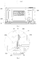
Fig. 3 is a structure diagram of cooperation between a cooking appliance and an adjustment shim of the present disclosure; -
Fig. 4 is an exploded structure diagram of the structure as shown inFig. 3 ; -
Fig. 5 is a sectional structure diagram along an A-A direction inFig. 3 ; -
Fig. 6 is an enlarged structure diagram of a B portion inFig. 5 ; -
Fig. 7 is a sectional structure diagram along a C-C direction inFig. 3 ; -
Fig. 8 is an enlarged structure diagram of a D portion inFig. 7 . - The corresponding relationship between reference signs and component names in
Figs. 1 to 8 is as follows:
100 adjustment shim, 10 connecting plate, 11 first positioning hole, 12 limiting notch, 13 connecting hole, 14 boss, 20 adjusting plate, 21 first positioning column, 22 second positioning column, 23 second positioning hole, 24 fixing hole, 30 connecting folded plate, 200 box body, 201 positioning groove, 202 mounting plate, 203 protrusion, 300 cupboard. - In order to more clearly understand the above objectives, features and advantages of the present disclosure, the present disclosure will be further described in detail below in combination with the drawings and specific embodiments. It should be noted that the embodiments of the present application and the features in the embodiments may be combined with each other without conflict.
- Numerous specific details are set forth in the following description in order to provide a thorough understanding of the present disclosure, but the present disclosure can also be implemented in other ways than described herein. Therefore the protection scope of the present disclosure is not limited by the specific embodiments described below. An
adjustment shim 100 according to the embodiment of the one aspect of the present disclosure is described below with reference toFigs. 1 to 8 . - As shown in
Fig. 1 , theadjustment shim 100 according to the embodiment of the one aspect of the present disclosure is arranged between a lateral wall of abox body 200 of an embedded cooking appliance and a lateral wall of acupboard 300 and is configured to adjust the distance between the lateral wall of thebox body 200 and the lateral wall of thecupboard 300. Theadjustment shim 100 includes a connectingplate 10 and an adjustingplate 20. - Specifically, the connecting
plate 10 is fixed on thebox body 200 or thecupboard 300, the adjustingplate 20 is connected to the connectingplate 10, and the adjustingplate 20 can rotate with respect to the connectingplate 10 and press against the connectingplate 10. - In the
adjustment shim 100 according to the present disclosure, the adjustingplate 20 is pressed against the connectingplate 10, namely, the size of the gap between the lateral wall of thebox body 200 of the cooking appliance and the lateral wall of thecupboard 300 is adjusted by changing the overall thickness of theadjustment shim 100 so as to adjust the distance therebetween. Thus, the good cooperation between the embedded cooking appliance and thecupboard 300 is guaranteed, and the situation that thebox body 200 shakes in thecupboard 300 caused by the too large distance therebetween is avoided, while preventing the situation that it is not easy to open the door body caused by the too small distance therebetween and guaranteeing the comfort during the use of the product. - In one embodiment of the present disclosure, as shown in
Fig. 1, Fig. 2 , andFig. 5 toFig. 8 , a plurality of adjustingplates 20 are arranged on the connectingplate 10, and the plurality of adjustingplates 20 can be pressed against the connectingplate 10 in a stacking manner are parallel to the connectingplate 10. - In the present embodiment, the thickness of the
adjustment shim 100 is adjusted by adjusting the number of the adjustingplates 20 pressed against the connectingplate 10 in the stacking manner so as to adjust the gap between the lateral wall of thebox body 200 and the lateral wall of thecupboard 300, thereby avoiding the situation of use inconvenience of the user due to the too large or too small distance therebetween, and guaranteeing the comfort during the use of the product. - In addition, one adjusting
plate 20 can also be connected to the connectingplate 10, and when the thickness of theadjustment shim 100 needs to be changed, the adjustingplate 20 is rotated with respect to the connectingplate 10, so that the adjustingplate 20 is vertical to the connectingplate 10. In this way, the thickness of theadjustment shim 100 can also be changed. In addition, the adjustingplate 20 can also be formed by splicing a plurality of sub-plates, and the thickness of theadjustment shim 100 is adjusted by adjusting the number of the sub-plates or folding the sub-plates. - In one embodiment of the present disclosure, as shown in
Fig. 1 , afirst positioning column 21 is arranged on one of the connectingplate 10 and the adjustingplate 20, afirst positioning hole 11 is formed in the other of the connectingplate 10 and the adjustingplate 20, and thefirst positioning column 21 can be inserted into thefirst positioning hole 11. Asecond positioning column 22 is arranged on one of twoadjacent adjusting plates 20, asecond positioning hole 23 is formed in the other of the twoadjacent adjusting plates 20, and thesecond positioning column 22 can be inserted into thesecond positioning hole 23. - In the present embodiment, due to the cooperation between the
first positioning column 21 and thefirst positioning hole 11 on the connectingplate 10 and the adjustingplate 20, the adjustingplate 20 can be fixed on the connectingplate 10, thereby ensuring the reliability of the connectingplate 10 and the adjustingplate 20 in use. Due to the cooperation between thesecond positioning column 22 and thesecond positioning hole 23 on the twoadjacent adjusting plates 20, the twoadjacent adjusting plates 20 can be fixedly connected, thereby ensuring the reliability of the adjustingplates 20 in use. Thus, the market competitiveness of the product is improved. - In one embodiment of the present disclosure, as shown in
Fig. 1 , a fixinghole 24 is formed in each adjustingplate 20, and a connecting piece sequentially penetrates the fixinghole 24 and the connectingplate 10 to be inserted into thebox body 200 or thecupboard 300, so that the adjustingplate 20 is fixedly connected to the connectingplate 10. - In the present embodiment, the connecting piece sequentially penetrates the connecting
plate 10 and the fixinghole 24 in the adjustingplate 20 and is inserted into thebox body 200 or thecupboard 300, which does not only guarantee the connection strength between the connectingplate 10 and the adjustingplate 20, but also improves the overall use reliability of the of theadjustment shim 100. Meanwhile, both of the connectingplate 10 and the adjustingplate 20 can be fixed on thebox body 200 or thecupboard 300, thereby greatly reducing the probability that theadjustment shim 100 falls from thebox body 200 or thecupboard 300, and ensuring the use reliability of the product. - In addition, as shown in
Fig. 1 , two second positioning holes 23 and twosecond positioning columns 22 are respectively arranged on theadjacent adjusting plates 20, each adjustingplate 20 is provided with one fixinghole 24, two second positioning holes 23 and twosecond positioning columns 22, three fixing points are arranged between theadjacent adjusting plates 20, thereby guaranteeing the connection strength of theadjacent adjusting plates 20, so that the use reliability of the product is guaranteed. - In one embodiment of the present disclosure, as shown in
Fig. 1 , one end of the connectingplate 10 is provided with a limitingnotch 12, and the connecting piece penetrates the limitingnotch 12 and is inserted into thebox body 200 or thecupboard 300. - In the present embodiment, one end of the connecting
plate 10 is provided with the limitingnotch 12, the connecting piece penetrates the limitingnotch 12 and is inserted into thebox body 200 or thecupboard 300, the limitingnotch 12 can not only enable the connecting piece to penetrate it and be inserted into thebox body 200 or thecupboard 300 to guarantee the connection strength between one end of the connecting piece and thebox body 200 or thecupboard 300, but can also limit the connecting piece to prevent the situation of left and right shake of the connectingplate 10 in use, thereby ensuring the reliability of the product during use. - In one embodiment of the present disclosure, as shown in
Fig. 1 , the other end of the connectingplate 10 is provided with a connectinghole 13, and a fastener penetrates the connectinghole 13 and is inserted into thebox body 200 or thecupboard 300 so as to connect the connectingplate 10 with thebox body 200 or thecupboard 300. - In the present embodiment, the other end of the connecting
plate 10 is provided with the connectinghole 13, and the fastener penetrates the connectinghole 13 and is inserted into thebox body 200 or thecupboard 300, thereby guaranteeing that the other end of the connectingplate 10 can be connected to thebox body 200 or thecupboard 300, and preventing the situation that the connectingplate 10 rotates around the connecting piece when one end of the connectingplate 10 is connected to thebox body 10 or thecupboard 300. Accordingly the balance and stability of fixing the connectingplate 10 on thebox body 200 or thecupboard 300 are improved. - In one embodiment of the present disclosure, the connecting
plate 10 is pivotally connected to the adjustingplate 20. - In the present embodiment, the connecting
plate 10 is pivotally connected to the adjustingplate 20. On the one hand, the connection strength between the connectingplate 10 and the adjustingplate 20 can be ensured, the probability of breakage between the connectingplate 10 and the adjustingplate 20 is greatly reduced, and the use reliability of theadjustment shim 100 is guaranteed. On the other hand, it is ensured that the adjustingplate 20 can rotated relative to the connectingplate 10, so that the adjustingplate 20 can be overlapped on the connectingplate 10, and the function of adjusting the thickness of theadjustment shim 100 is achieved, thereby adjusting the size of the gap between the connectingplate 10 and the adjustingplate 20, and guaranteeing that theadjustment shim 100 can work normally. - In one embodiment of the present disclosure, as shown in
Fig. 1 , the connectingplate 10 and the adjustingplate 20 are connected by a connecting foldedplate 30, and the connecting foldedplate 30 can be bent relative to the connectingplate 10. - In the present embodiment, the connecting
plate 10 and the adjustingplate 20 are connected by the connecting foldedplate 30, and the connecting foldedplate 30 can be bent relative to the connectingplate 10, so that the adjustingplate 20 can be pressed against the connectingplate 10 and can be mutually overlapped with the connectingplate 10, thereby ensuring the function of adjusting the thickness of theadjustment shim 100 by the adjustingplate 20. Thus, the use reliability of theadjustment shim 100 is guaranteed. - In one embodiment of the present disclosure, the connecting
plate 10, the plurality of adjustingplates 20 and the connecting foldedplate 30 are of an integrated structure. - In the present embodiment, the connecting
plate 10, the adjustingplates 20 and the connecting foldedplate 30 are of the integrated structure. On one hand, the connection strength of the above three kinds of plates is ensured, and the breakage probability of theadjustment shim 100 in use is greatly reduced, and the use reliability of theadjustment shim 100 is guaranteed. On the other hand, it is convenient to process the integrated structure, and the production steps of the product is greatly simplified. Thus, the assembly efficiency of the product is improved. - As shown in
Figs. 3 and 4 , an embedded cooking appliance assembly in accordance with the embodiment of the second aspect of the present disclosure, is installed in acupboard 300, and includes abox body 200 of an embedded cooking appliance, which is installed in thecupboard 300, and theadjustment shim 100 in accordance with any one of the above embodiments, which is arranged between thebox body 200 and thecupboard 300. - The embedded cooking appliance assembly in accordance with the embodiment of the second aspect of the present disclosure is installed in the
cupboard 300, and includes thebox body 200 of the embedded cooking appliance, which is installed in thecupboard 300, and theadjustment shim 100 of any one of the above embodiments, which is arranged between thebox body 200 and thecupboard 300, and thus has all the above beneficial effects which are not repeated herein. In addition, theadjustment shim 100 is further applicable to an embedded dish-washing machine, an embedded disinfection cabinet, an embedded oven and other embedded appliances, and has the beneficial effects of the shim in any one of the above embodiments. - In one embodiment of the present disclosure, as shown in
Fig. 3 to Fig. 8 , theadjustment shim 100 is arranged on an outer lateral wall of an outer cover of thebox body 200, a protrusion matched with the limitingnotch 12 is arranged on the outer cover, and the protrusion is inserted into the limitingnotch 12. - In the present embodiment, the protrusion is arranged on the outer cover of the box body, and the protrusion is inserted into the limiting
notch 12 on the connectingplate 10, so that the adjustingplate 20 is connected to the outer cover, and the connection of the connectingplate 10 on the outer cover can be limited, thereby guaranteeing the connection strength and stability of the connectingplate 10 on the outer cover. Accordingly, the use reliability of the product is improved. - In addition, as shown in
Fig. 6 andFig. 8 , a mountingplate 202 is further arranged in the embedded cooking appliance assembly, theadjustment shim 100 is fixed on the box body through the mountingplate 202, aboss 14 is arranged on the other end of the connectingplate 10, apositioning groove 201 is formed in the outer cover, and theboss 14 is inserted into thepositioning groove 201, thereby guaranteeing the mounting precision of the connectingplate 10. In addition, the protrusion arranged on the outer cover can also be arranged on the mountingplate 202, theprotrusion 203 on the mountingplate 202 is formed by depressing the mountingplate 202, and theprotrusion 203 is inserted into the limitingnotch 12. - In one embodiment of the present disclosure, as shown in
Fig. 3 to Fig.8 , twoadjustment shims 100 are arranged on thebox body 200. - In the present embodiment, two
adjustment shims 100 are arranged on thebox body 200. On one hand, if the number of the adjustment shims 100 is too few, thebox body 200 may shake in thecupboard 300, that is, the stability of the cooking appliance cannot be guaranteed. On the other hand, if the number of the adjustment shims 100 are too many, the cost of the product is increased. Thus, by setting the twoadjustment shims 100, not only is the stability of fixing thebox body 200 of the cooking appliance guaranteed, but also the cost of the product is reduced, so that the market competitiveness of the product is improved. - In the adjustment shim of the present disclosure, the connecting plate is fixed on the box body or the cupboard, the adjusting plate is pressed against the connecting plate, namely, the overall thickness of the adjustment shim is changed to adjust the size of the gap between the lateral wall of the box body and the lateral wall of the cupboard so as to adjust the distance therebetween. Thus, the good cooperation between the embedded cooking appliance and the cupboard is guaranteed, thereby avoiding the situation of use inconvenience of the user due to the too large or too small distance therebetween, and the comfort during the use of the product is guaranteed. Specifically, in the case of the embedded cooking appliance in the related art, since the size of the cupboard is larger than that of the cupboard of the cooking appliance, the gap between the box body and the inner wall of the cupboard is either too large or too small, thereby resulting in the situation that the box body shakes or it is not easy to open the door body when the embedded cooking appliance is in use. On the contrary, in the adjustment shim of the present disclosure, the connecting plate is fixed on the box body or the cupboard, the adjusting plate is pressed against the connecting plate, namely, the overall thickness of the adjustment shim is changed to adjust the size of the gap between the lateral wall of the box body of the cooking appliance and the lateral wall of the cupboard so as to adjust the distance therebetween. Thus, the good cooperation between the embedded cooking appliance and the cupboard is guaranteed, thereby avoiding the situation that the box body shakes in the cupboard, which is caused by the too large distance therebetween, while preventing the situation that it is not easy to open the door body, which is caused by the too small distance therebetween, and guaranteeing the comfort during the use of the product.
- In the present disclosure, the terms "first" and "second" are used for the purpose of description only, and cannot be construed as indicating or implying relative importance. The term "plurality" means two or more unless otherwise clearly defined. The terms "installation", "connected", "connection", "fixing" and the like should be understood broadly. For example, the "connection" may be a fixed connection, a detachable connection, or an integral connection; the "connected" can be directly connected or indirectly connected through an intermediary medium. Those of ordinary skill in the art can understand the specific meanings of the above terms in the present disclosure according to specific conditions.
- In the description of the present specification, the description of the terms "one embodiment", "some embodiments", "specific embodiments" and the like means that the specific features, structures, materials or characteristics described in combination with the embodiments or examples are contained in at least one embodiment or example of the present disclosure. In the present specification, the schematic representation of the above terms does not necessarily refer to the same embodiment or example. Furthermore, the particular features, structures, materials or characteristics described may be combined in a suitable manner in any one or more embodiments or examples.
- Described above are only preferred embodiments of the present disclosure, which are not intended to limit the present disclosure, and various modifications and changes can be made to the present disclosure by those skilled in the art. Any modifications, equivalent substitutions, improvements and the like made within the spirit and scope of the present disclosure should also be encompassed within the protection scope of the present disclosure.
Claims (12)
- An adjustment shim, arranged between a lateral wall of a box body of an embedded cooking appliance and a lateral wall of a cupboard and be configured to adjust the distance between the lateral wall of the box body and the lateral wall of the cupboard, wherein the adjustment shim comprises:a connecting plate fixed on the box body or the cupboard; andan adjusting plate connected to the connecting plate and being capable of rotating with respect to the connecting plate and pressing against the connecting plate.
- The adjustment shim according to claim 1, wherein
a plurality of adjusting plates are arranged on the connecting plate, and the plurality of adjusting plates can be pressed against the connecting plate in a stacking manner and are parallel to the connecting plate. - The adjustment shim according to claim 2, wherein
a first positioning column is arranged on one of the connecting plate and the adjusting plate, and a first positioning hole, into which the first positioning column can be inserted, is formed in the other of the connecting plate and the adjusting plate; and
a second positioning column is arranged on one of two adjacent adjusting plates of the plurality of adjusting plates, and a second positioning hole, into which the second positioning column can be inserted, is formed in the other of the two adjacent adjusting plates. - The adjustment shim according to claim 1, wherein
a fixing hole is formed in each adjusting plate, and a connecting piece sequentially penetrates the fixing hole and the connecting plate to be inserted into the box body or the cupboard, so that the adjusting plate is fixedly connected to the connecting plate. - The adjustment shim according to claim 4, wherein
one end of the connecting plate is provided with a limiting notch, and the connecting piece penetrates the limiting notch and is inserted into the box body or the cupboard. - The adjustment shim according to claim 5, wherein
the other end of the connecting plate is provided with a connecting hole, and a fastener penetrates the connecting hole and is inserted into the box body or the cupboard so as to connect the connecting plate with the box body or the cupboard. - The adjustment shim according to any one of claims 1-6, wherein
the connecting plate is pivotally connected to the adjusting plate. - The adjustment shim according to any one of claims 1-6, wherein
the connecting plate and the adjusting plate are connected by a connecting folded plate, and the connecting folded plate can be bent relative to the connecting plate. - The adjustment shim according to claim 8, wherein
the connecting plate, the plurality of adjusting plates and the connecting folded plate are of an integrated structure. - An embedded cooking appliance assembly, installed in a cupboard, comprising:a box body of an embedded cooking appliance, wherein the box body is installed in the cupboard; andthe adjustment shim according to any one of claims 1-9, which is arranged between the box body and the cupboard.
- The embedded cooking appliance assembly according to claim 10, wherein
the adjustment shim is arranged on an outer lateral wall of an outer cover of the box body, a protrusion matched with the limiting notch of the adjustment shim is arranged on the outer cover, and the protrusion is inserted into the limiting notch. - The embedded cooking appliance assembly according to claim 10, wherein
two adjustment shims are arranged on the box body.
Applications Claiming Priority (3)
| Application Number | Priority Date | Filing Date | Title |
|---|---|---|---|
| CN201610200383.6A CN105708195B (en) | 2016-03-31 | 2016-03-31 | Adjusting gasket and built-in cooking appliance component |
| CN201620267426.8U CN205696659U (en) | 2016-03-31 | 2016-03-31 | Regulation pad and built-in cooking appliance assembly |
| PCT/CN2016/087163 WO2017166456A1 (en) | 2016-03-31 | 2016-06-24 | Adjustment shim and embedded cooking utensil assembly |
Publications (3)
| Publication Number | Publication Date |
|---|---|
| EP3437516A1 true EP3437516A1 (en) | 2019-02-06 |
| EP3437516A4 EP3437516A4 (en) | 2019-02-06 |
| EP3437516B1 EP3437516B1 (en) | 2020-09-16 |
Family
ID=59963353
Family Applications (1)
| Application Number | Title | Priority Date | Filing Date |
|---|---|---|---|
| EP16896229.8A Active EP3437516B1 (en) | 2016-03-31 | 2016-06-24 | Adjustment shim and embedded cooking utensil assembly |
Country Status (2)
| Country | Link |
|---|---|
| EP (1) | EP3437516B1 (en) |
| WO (1) | WO2017166456A1 (en) |
Families Citing this family (2)
| Publication number | Priority date | Publication date | Assignee | Title |
|---|---|---|---|---|
| CN117308466A (en) * | 2022-06-23 | 2023-12-29 | 青岛海尔电冰箱有限公司 | Anti-tipping component and refrigerator |
| CN116076976A (en) * | 2022-11-18 | 2023-05-09 | 陕西康佳智能家电有限公司 | An adjustment mechanism and built-in dishwasher |
Family Cites Families (10)
| Publication number | Priority date | Publication date | Assignee | Title |
|---|---|---|---|---|
| DE6905423U (en) * | 1969-02-12 | 1969-11-13 | Bosch Hausgeraete Gmbh | DEVICE FOR FASTENING A BUILT-IN DEVICE, IN PARTICULAR ENES BUILT-IN REFRIGERATOR |
| DE2529801A1 (en) * | 1974-07-10 | 1976-02-05 | Teruo Ohashi | PRE-FABRICATED REFRIGERATOR AND FREEZER |
| AT502937B1 (en) * | 2005-04-28 | 2013-06-15 | Blum Gmbh Julius | CABINET FURNITURE |
| CN201029613Y (en) * | 2007-05-22 | 2008-03-05 | 李庆祥 | Multipurpose shaking-proof pad |
| DE102008006521B4 (en) * | 2008-01-29 | 2020-07-09 | BSH Hausgeräte GmbH | Spacer, built-in household appliance and household appliance installation system |
| CN201480596U (en) * | 2009-08-21 | 2010-05-26 | 李卉 | Table foot pad |
| IT1403721B1 (en) * | 2011-01-05 | 2013-10-31 | Electrolux Home Prod Corp | BUILT-IN ELECTRIC APPLIANCES AND ASSEMBLY OF BUILT-IN AND MOBILE APPLIANCES FOR BUILT-IN APPLIANCES. |
| DE102011007410A1 (en) * | 2011-04-14 | 2012-10-18 | BSH Bosch und Siemens Hausgeräte GmbH | Built-in refrigeration unit with a fitting component |
| CN204908611U (en) * | 2015-08-06 | 2015-12-30 | 江苏省麒麟铸业有限公司 | Drawer safety handle |
| CN105361467B (en) * | 2015-12-10 | 2017-11-10 | 广东美的厨房电器制造有限公司 | Cooking apparatus |
-
2016
- 2016-06-24 WO PCT/CN2016/087163 patent/WO2017166456A1/en not_active Ceased
- 2016-06-24 EP EP16896229.8A patent/EP3437516B1/en active Active
Also Published As
| Publication number | Publication date |
|---|---|
| WO2017166456A1 (en) | 2017-10-05 |
| EP3437516B1 (en) | 2020-09-16 |
| EP3437516A4 (en) | 2019-02-06 |
Similar Documents
| Publication | Publication Date | Title |
|---|---|---|
| CN205125972U (en) | Upper cover subassembly and cooking utensil | |
| EP3722715B1 (en) | Drawer assembly structure and refrigerator having same | |
| EP3437516B1 (en) | Adjustment shim and embedded cooking utensil assembly | |
| USD958368S1 (en) | Laminoplasty hinged plate with integrated spacer | |
| CN204765005U (en) | Upper cover subassembly and electric pressure cooker | |
| CN105342472B (en) | Door body and cooking apparatus | |
| CN216010225U (en) | Torsional spring hinge assembly | |
| CN105708195B (en) | Adjusting gasket and built-in cooking appliance component | |
| CN205696659U (en) | Regulation pad and built-in cooking appliance assembly | |
| CN204091682U (en) | Steam cooking vessel | |
| CN105411401A (en) | Door and cooking utensil | |
| CN107356044B (en) | Refrigerator and partition plate thereof | |
| CN203969707U (en) | A kind of cupboard and keel section thereof | |
| CN104533200A (en) | Lower hinge structure and refrigerator | |
| CN205322125U (en) | Door body and cooking utensil | |
| CN104389487B (en) | For the door body structure of household electrical appliance | |
| CN204238768U (en) | For the door body structure of household electrical appliance | |
| EP3351859A1 (en) | A one-piece fastening element for a cooking hob | |
| CN210739758U (en) | Display screen mounting structure | |
| CN104223935A (en) | Steam cooking apparatus | |
| CN208425054U (en) | A kind of clamp device of plate | |
| EP2937017B1 (en) | Mounting device for drawer system | |
| CN114652159A (en) | cooking utensils | |
| CN217987327U (en) | Lid assembly and have its cooking utensil | |
| US8274785B2 (en) | Electronic apparatus with drive bracket |
Legal Events
| Date | Code | Title | Description |
|---|---|---|---|
| STAA | Information on the status of an ep patent application or granted ep patent |
Free format text: STATUS: THE INTERNATIONAL PUBLICATION HAS BEEN MADE |
|
| PUAI | Public reference made under article 153(3) epc to a published international application that has entered the european phase |
Free format text: ORIGINAL CODE: 0009012 |
|
| STAA | Information on the status of an ep patent application or granted ep patent |
Free format text: STATUS: REQUEST FOR EXAMINATION WAS MADE |
|
| 17P | Request for examination filed |
Effective date: 20181029 |
|
| A4 | Supplementary search report drawn up and despatched |
Effective date: 20181207 |
|
| AK | Designated contracting states |
Kind code of ref document: A1 Designated state(s): AL AT BE BG CH CY CZ DE DK EE ES FI FR GB GR HR HU IE IS IT LI LT LU LV MC MK MT NL NO PL PT RO RS SE SI SK SM TR |
|
| AX | Request for extension of the european patent |
Extension state: BA ME |
|
| DAV | Request for validation of the european patent (deleted) | ||
| DAX | Request for extension of the european patent (deleted) | ||
| RIC1 | Information provided on ipc code assigned before grant |
Ipc: A47B 95/00 20060101ALI20190930BHEP Ipc: F24C 15/30 20060101ALN20190930BHEP Ipc: A47B 77/08 20060101AFI20190930BHEP |
|
| STAA | Information on the status of an ep patent application or granted ep patent |
Free format text: STATUS: EXAMINATION IS IN PROGRESS |
|
| RIC1 | Information provided on ipc code assigned before grant |
Ipc: F24C 15/30 20060101ALN20191104BHEP Ipc: A47B 95/00 20060101ALI20191104BHEP Ipc: A47B 77/08 20060101AFI20191104BHEP |
|
| 17Q | First examination report despatched |
Effective date: 20191113 |
|
| GRAP | Despatch of communication of intention to grant a patent |
Free format text: ORIGINAL CODE: EPIDOSNIGR1 |
|
| STAA | Information on the status of an ep patent application or granted ep patent |
Free format text: STATUS: GRANT OF PATENT IS INTENDED |
|
| RIC1 | Information provided on ipc code assigned before grant |
Ipc: A47B 95/00 20060101ALI20200429BHEP Ipc: F24C 15/30 20060101ALN20200429BHEP Ipc: A47B 77/08 20060101AFI20200429BHEP |
|
| RIC1 | Information provided on ipc code assigned before grant |
Ipc: F24C 15/30 20060101ALN20200506BHEP Ipc: A47B 95/00 20060101ALI20200506BHEP Ipc: A47B 77/08 20060101AFI20200506BHEP |
|
| INTG | Intention to grant announced |
Effective date: 20200519 |
|
| GRAS | Grant fee paid |
Free format text: ORIGINAL CODE: EPIDOSNIGR3 |
|
| GRAA | (expected) grant |
Free format text: ORIGINAL CODE: 0009210 |
|
| STAA | Information on the status of an ep patent application or granted ep patent |
Free format text: STATUS: THE PATENT HAS BEEN GRANTED |
|
| AK | Designated contracting states |
Kind code of ref document: B1 Designated state(s): AL AT BE BG CH CY CZ DE DK EE ES FI FR GB GR HR HU IE IS IT LI LT LU LV MC MK MT NL NO PL PT RO RS SE SI SK SM TR |
|
| REG | Reference to a national code |
Ref country code: GB Ref legal event code: FG4D |
|
| REG | Reference to a national code |
Ref country code: CH Ref legal event code: EP |
|
| REG | Reference to a national code |
Ref country code: DE Ref legal event code: R096 Ref document number: 602016044341 Country of ref document: DE |
|
| REG | Reference to a national code |
Ref country code: IE Ref legal event code: FG4D |
|
| REG | Reference to a national code |
Ref country code: AT Ref legal event code: REF Ref document number: 1313325 Country of ref document: AT Kind code of ref document: T Effective date: 20201015 |
|
| PG25 | Lapsed in a contracting state [announced via postgrant information from national office to epo] |
Ref country code: GR Free format text: LAPSE BECAUSE OF FAILURE TO SUBMIT A TRANSLATION OF THE DESCRIPTION OR TO PAY THE FEE WITHIN THE PRESCRIBED TIME-LIMIT Effective date: 20201217 Ref country code: SE Free format text: LAPSE BECAUSE OF FAILURE TO SUBMIT A TRANSLATION OF THE DESCRIPTION OR TO PAY THE FEE WITHIN THE PRESCRIBED TIME-LIMIT Effective date: 20200916 Ref country code: HR Free format text: LAPSE BECAUSE OF FAILURE TO SUBMIT A TRANSLATION OF THE DESCRIPTION OR TO PAY THE FEE WITHIN THE PRESCRIBED TIME-LIMIT Effective date: 20200916 Ref country code: FI Free format text: LAPSE BECAUSE OF FAILURE TO SUBMIT A TRANSLATION OF THE DESCRIPTION OR TO PAY THE FEE WITHIN THE PRESCRIBED TIME-LIMIT Effective date: 20200916 Ref country code: BG Free format text: LAPSE BECAUSE OF FAILURE TO SUBMIT A TRANSLATION OF THE DESCRIPTION OR TO PAY THE FEE WITHIN THE PRESCRIBED TIME-LIMIT Effective date: 20201216 Ref country code: NO Free format text: LAPSE BECAUSE OF FAILURE TO SUBMIT A TRANSLATION OF THE DESCRIPTION OR TO PAY THE FEE WITHIN THE PRESCRIBED TIME-LIMIT Effective date: 20201216 |
|
| REG | Reference to a national code |
Ref country code: AT Ref legal event code: MK05 Ref document number: 1313325 Country of ref document: AT Kind code of ref document: T Effective date: 20200916 |
|
| REG | Reference to a national code |
Ref country code: NL Ref legal event code: MP Effective date: 20200916 |
|
| PG25 | Lapsed in a contracting state [announced via postgrant information from national office to epo] |
Ref country code: RS Free format text: LAPSE BECAUSE OF FAILURE TO SUBMIT A TRANSLATION OF THE DESCRIPTION OR TO PAY THE FEE WITHIN THE PRESCRIBED TIME-LIMIT Effective date: 20200916 Ref country code: LV Free format text: LAPSE BECAUSE OF FAILURE TO SUBMIT A TRANSLATION OF THE DESCRIPTION OR TO PAY THE FEE WITHIN THE PRESCRIBED TIME-LIMIT Effective date: 20200916 |
|
| REG | Reference to a national code |
Ref country code: LT Ref legal event code: MG4D |
|
| PG25 | Lapsed in a contracting state [announced via postgrant information from national office to epo] |
Ref country code: LT Free format text: LAPSE BECAUSE OF FAILURE TO SUBMIT A TRANSLATION OF THE DESCRIPTION OR TO PAY THE FEE WITHIN THE PRESCRIBED TIME-LIMIT Effective date: 20200916 Ref country code: CZ Free format text: LAPSE BECAUSE OF FAILURE TO SUBMIT A TRANSLATION OF THE DESCRIPTION OR TO PAY THE FEE WITHIN THE PRESCRIBED TIME-LIMIT Effective date: 20200916 Ref country code: RO Free format text: LAPSE BECAUSE OF FAILURE TO SUBMIT A TRANSLATION OF THE DESCRIPTION OR TO PAY THE FEE WITHIN THE PRESCRIBED TIME-LIMIT Effective date: 20200916 Ref country code: PT Free format text: LAPSE BECAUSE OF FAILURE TO SUBMIT A TRANSLATION OF THE DESCRIPTION OR TO PAY THE FEE WITHIN THE PRESCRIBED TIME-LIMIT Effective date: 20210118 Ref country code: EE Free format text: LAPSE BECAUSE OF FAILURE TO SUBMIT A TRANSLATION OF THE DESCRIPTION OR TO PAY THE FEE WITHIN THE PRESCRIBED TIME-LIMIT Effective date: 20200916 Ref country code: SM Free format text: LAPSE BECAUSE OF FAILURE TO SUBMIT A TRANSLATION OF THE DESCRIPTION OR TO PAY THE FEE WITHIN THE PRESCRIBED TIME-LIMIT Effective date: 20200916 |
|
| PG25 | Lapsed in a contracting state [announced via postgrant information from national office to epo] |
Ref country code: AL Free format text: LAPSE BECAUSE OF FAILURE TO SUBMIT A TRANSLATION OF THE DESCRIPTION OR TO PAY THE FEE WITHIN THE PRESCRIBED TIME-LIMIT Effective date: 20200916 Ref country code: AT Free format text: LAPSE BECAUSE OF FAILURE TO SUBMIT A TRANSLATION OF THE DESCRIPTION OR TO PAY THE FEE WITHIN THE PRESCRIBED TIME-LIMIT Effective date: 20200916 Ref country code: ES Free format text: LAPSE BECAUSE OF FAILURE TO SUBMIT A TRANSLATION OF THE DESCRIPTION OR TO PAY THE FEE WITHIN THE PRESCRIBED TIME-LIMIT Effective date: 20200916 Ref country code: PL Free format text: LAPSE BECAUSE OF FAILURE TO SUBMIT A TRANSLATION OF THE DESCRIPTION OR TO PAY THE FEE WITHIN THE PRESCRIBED TIME-LIMIT Effective date: 20200916 Ref country code: IS Free format text: LAPSE BECAUSE OF FAILURE TO SUBMIT A TRANSLATION OF THE DESCRIPTION OR TO PAY THE FEE WITHIN THE PRESCRIBED TIME-LIMIT Effective date: 20210116 |
|
| REG | Reference to a national code |
Ref country code: DE Ref legal event code: R097 Ref document number: 602016044341 Country of ref document: DE |
|
| PG25 | Lapsed in a contracting state [announced via postgrant information from national office to epo] |
Ref country code: SK Free format text: LAPSE BECAUSE OF FAILURE TO SUBMIT A TRANSLATION OF THE DESCRIPTION OR TO PAY THE FEE WITHIN THE PRESCRIBED TIME-LIMIT Effective date: 20200916 |
|
| PLBE | No opposition filed within time limit |
Free format text: ORIGINAL CODE: 0009261 |
|
| STAA | Information on the status of an ep patent application or granted ep patent |
Free format text: STATUS: NO OPPOSITION FILED WITHIN TIME LIMIT |
|
| 26N | No opposition filed |
Effective date: 20210617 |
|
| PG25 | Lapsed in a contracting state [announced via postgrant information from national office to epo] |
Ref country code: SI Free format text: LAPSE BECAUSE OF FAILURE TO SUBMIT A TRANSLATION OF THE DESCRIPTION OR TO PAY THE FEE WITHIN THE PRESCRIBED TIME-LIMIT Effective date: 20200916 Ref country code: DK Free format text: LAPSE BECAUSE OF FAILURE TO SUBMIT A TRANSLATION OF THE DESCRIPTION OR TO PAY THE FEE WITHIN THE PRESCRIBED TIME-LIMIT Effective date: 20200916 |
|
| PG25 | Lapsed in a contracting state [announced via postgrant information from national office to epo] |
Ref country code: IT Free format text: LAPSE BECAUSE OF FAILURE TO SUBMIT A TRANSLATION OF THE DESCRIPTION OR TO PAY THE FEE WITHIN THE PRESCRIBED TIME-LIMIT Effective date: 20200916 |
|
| PG25 | Lapsed in a contracting state [announced via postgrant information from national office to epo] |
Ref country code: MC Free format text: LAPSE BECAUSE OF FAILURE TO SUBMIT A TRANSLATION OF THE DESCRIPTION OR TO PAY THE FEE WITHIN THE PRESCRIBED TIME-LIMIT Effective date: 20200916 |
|
| REG | Reference to a national code |
Ref country code: CH Ref legal event code: PL |
|
| GBPC | Gb: european patent ceased through non-payment of renewal fee |
Effective date: 20210624 |
|
| REG | Reference to a national code |
Ref country code: BE Ref legal event code: MM Effective date: 20210630 |
|
| PG25 | Lapsed in a contracting state [announced via postgrant information from national office to epo] |
Ref country code: LU Free format text: LAPSE BECAUSE OF NON-PAYMENT OF DUE FEES Effective date: 20210624 |
|
| PG25 | Lapsed in a contracting state [announced via postgrant information from national office to epo] |
Ref country code: LI Free format text: LAPSE BECAUSE OF NON-PAYMENT OF DUE FEES Effective date: 20210630 Ref country code: IE Free format text: LAPSE BECAUSE OF NON-PAYMENT OF DUE FEES Effective date: 20210624 Ref country code: GB Free format text: LAPSE BECAUSE OF NON-PAYMENT OF DUE FEES Effective date: 20210624 Ref country code: CH Free format text: LAPSE BECAUSE OF NON-PAYMENT OF DUE FEES Effective date: 20210630 |
|
| PG25 | Lapsed in a contracting state [announced via postgrant information from national office to epo] |
Ref country code: FR Free format text: LAPSE BECAUSE OF NON-PAYMENT OF DUE FEES Effective date: 20210630 |
|
| PG25 | Lapsed in a contracting state [announced via postgrant information from national office to epo] |
Ref country code: BE Free format text: LAPSE BECAUSE OF NON-PAYMENT OF DUE FEES Effective date: 20210630 |
|
| PG25 | Lapsed in a contracting state [announced via postgrant information from national office to epo] |
Ref country code: NL Free format text: LAPSE BECAUSE OF NON-PAYMENT OF DUE FEES Effective date: 20200923 Ref country code: CY Free format text: LAPSE BECAUSE OF FAILURE TO SUBMIT A TRANSLATION OF THE DESCRIPTION OR TO PAY THE FEE WITHIN THE PRESCRIBED TIME-LIMIT Effective date: 20200916 |
|
| PG25 | Lapsed in a contracting state [announced via postgrant information from national office to epo] |
Ref country code: HU Free format text: LAPSE BECAUSE OF FAILURE TO SUBMIT A TRANSLATION OF THE DESCRIPTION OR TO PAY THE FEE WITHIN THE PRESCRIBED TIME-LIMIT; INVALID AB INITIO Effective date: 20160624 |
|
| PG25 | Lapsed in a contracting state [announced via postgrant information from national office to epo] |
Ref country code: MK Free format text: LAPSE BECAUSE OF FAILURE TO SUBMIT A TRANSLATION OF THE DESCRIPTION OR TO PAY THE FEE WITHIN THE PRESCRIBED TIME-LIMIT Effective date: 20200916 |
|
| PG25 | Lapsed in a contracting state [announced via postgrant information from national office to epo] |
Ref country code: TR Free format text: LAPSE BECAUSE OF FAILURE TO SUBMIT A TRANSLATION OF THE DESCRIPTION OR TO PAY THE FEE WITHIN THE PRESCRIBED TIME-LIMIT Effective date: 20200916 |
|
| PG25 | Lapsed in a contracting state [announced via postgrant information from national office to epo] |
Ref country code: MT Free format text: LAPSE BECAUSE OF FAILURE TO SUBMIT A TRANSLATION OF THE DESCRIPTION OR TO PAY THE FEE WITHIN THE PRESCRIBED TIME-LIMIT Effective date: 20200916 |
|
| PGFP | Annual fee paid to national office [announced via postgrant information from national office to epo] |
Ref country code: DE Payment date: 20250625 Year of fee payment: 10 |