EP3437451A1 - Spectrometer assembly - Google Patents
Spectrometer assembly Download PDFInfo
- Publication number
- EP3437451A1 EP3437451A1 EP18185776.4A EP18185776A EP3437451A1 EP 3437451 A1 EP3437451 A1 EP 3437451A1 EP 18185776 A EP18185776 A EP 18185776A EP 3437451 A1 EP3437451 A1 EP 3437451A1
- Authority
- EP
- European Patent Office
- Prior art keywords
- sample
- detector
- spectrometer
- source
- waves
- Prior art date
- Legal status (The legal status is an assumption and is not a legal conclusion. Google has not performed a legal analysis and makes no representation as to the accuracy of the status listed.)
- Granted
Links
- 238000001514 detection method Methods 0.000 claims abstract description 28
- 230000005540 biological transmission Effects 0.000 claims abstract description 10
- 239000000523 sample Substances 0.000 claims description 70
- 238000001228 spectrum Methods 0.000 claims description 25
- 239000004615 ingredient Substances 0.000 claims description 19
- 238000011156 evaluation Methods 0.000 claims description 16
- 230000001419 dependent effect Effects 0.000 claims description 6
- 238000012546 transfer Methods 0.000 claims description 6
- 230000005284 excitation Effects 0.000 description 17
- 239000002689 soil Substances 0.000 description 16
- 238000001069 Raman spectroscopy Methods 0.000 description 8
- 239000002245 particle Substances 0.000 description 8
- 239000003337 fertilizer Substances 0.000 description 7
- OAICVXFJPJFONN-UHFFFAOYSA-N Phosphorus Chemical compound [P] OAICVXFJPJFONN-UHFFFAOYSA-N 0.000 description 5
- 210000003608 fece Anatomy 0.000 description 5
- 239000007788 liquid Substances 0.000 description 5
- 239000010871 livestock manure Substances 0.000 description 5
- 230000003287 optical effect Effects 0.000 description 5
- 239000011574 phosphorus Substances 0.000 description 5
- 229910052698 phosphorus Inorganic materials 0.000 description 5
- 238000000034 method Methods 0.000 description 4
- 239000000126 substance Substances 0.000 description 4
- 241000196324 Embryophyta Species 0.000 description 3
- ZLMJMSJWJFRBEC-UHFFFAOYSA-N Potassium Chemical compound [K] ZLMJMSJWJFRBEC-UHFFFAOYSA-N 0.000 description 3
- 238000001237 Raman spectrum Methods 0.000 description 3
- 239000000470 constituent Substances 0.000 description 3
- 238000005259 measurement Methods 0.000 description 3
- 239000011591 potassium Substances 0.000 description 3
- 229910052700 potassium Inorganic materials 0.000 description 3
- 238000009331 sowing Methods 0.000 description 3
- 230000003595 spectral effect Effects 0.000 description 3
- 238000012935 Averaging Methods 0.000 description 2
- 239000007787 solid Substances 0.000 description 2
- 238000004611 spectroscopical analysis Methods 0.000 description 2
- 239000007921 spray Substances 0.000 description 2
- 238000005507 spraying Methods 0.000 description 2
- WWYRMDQMQJHTMN-UHFFFAOYSA-N CCCC(N=O)=C Chemical compound CCCC(N=O)=C WWYRMDQMQJHTMN-UHFFFAOYSA-N 0.000 description 1
- 238000004497 NIR spectroscopy Methods 0.000 description 1
- 238000005299 abrasion Methods 0.000 description 1
- 238000010521 absorption reaction Methods 0.000 description 1
- 238000004458 analytical method Methods 0.000 description 1
- 238000013459 approach Methods 0.000 description 1
- 238000000149 argon plasma sintering Methods 0.000 description 1
- 230000000712 assembly Effects 0.000 description 1
- 238000000429 assembly Methods 0.000 description 1
- 230000002238 attenuated effect Effects 0.000 description 1
- 239000003795 chemical substances by application Substances 0.000 description 1
- 238000012569 chemometric method Methods 0.000 description 1
- 238000010276 construction Methods 0.000 description 1
- 238000012937 correction Methods 0.000 description 1
- 239000006185 dispersion Substances 0.000 description 1
- 230000000694 effects Effects 0.000 description 1
- 239000000835 fiber Substances 0.000 description 1
- 239000011521 glass Substances 0.000 description 1
- 238000005286 illumination Methods 0.000 description 1
- 238000003384 imaging method Methods 0.000 description 1
- 229910052500 inorganic mineral Inorganic materials 0.000 description 1
- 239000000463 material Substances 0.000 description 1
- 239000011707 mineral Substances 0.000 description 1
- 238000010899 nucleation Methods 0.000 description 1
- 238000003825 pressing Methods 0.000 description 1
- 238000011160 research Methods 0.000 description 1
- 238000012552 review Methods 0.000 description 1
- 229910052594 sapphire Inorganic materials 0.000 description 1
- 239000010980 sapphire Substances 0.000 description 1
- -1 seeds Substances 0.000 description 1
- 239000004065 semiconductor Substances 0.000 description 1
- 230000035945 sensitivity Effects 0.000 description 1
- 230000001953 sensory effect Effects 0.000 description 1
- 239000004460 silage Substances 0.000 description 1
- 239000013589 supplement Substances 0.000 description 1
- 238000004846 x-ray emission Methods 0.000 description 1
Images


Classifications
-
- G—PHYSICS
- G01—MEASURING; TESTING
- G01N—INVESTIGATING OR ANALYSING MATERIALS BY DETERMINING THEIR CHEMICAL OR PHYSICAL PROPERTIES
- G01N21/00—Investigating or analysing materials by the use of optical means, i.e. using sub-millimetre waves, infrared, visible or ultraviolet light
- G01N21/17—Systems in which incident light is modified in accordance with the properties of the material investigated
- G01N21/25—Colour; Spectral properties, i.e. comparison of effect of material on the light at two or more different wavelengths or wavelength bands
- G01N21/31—Investigating relative effect of material at wavelengths characteristic of specific elements or molecules, e.g. atomic absorption spectrometry
- G01N21/314—Investigating relative effect of material at wavelengths characteristic of specific elements or molecules, e.g. atomic absorption spectrometry with comparison of measurements at specific and non-specific wavelengths
- G01N21/3151—Investigating relative effect of material at wavelengths characteristic of specific elements or molecules, e.g. atomic absorption spectrometry with comparison of measurements at specific and non-specific wavelengths using two sources of radiation of different wavelengths
-
- A—HUMAN NECESSITIES
- A01—AGRICULTURE; FORESTRY; ANIMAL HUSBANDRY; HUNTING; TRAPPING; FISHING
- A01B—SOIL WORKING IN AGRICULTURE OR FORESTRY; PARTS, DETAILS, OR ACCESSORIES OF AGRICULTURAL MACHINES OR IMPLEMENTS, IN GENERAL
- A01B76/00—Parts, details or accessories of agricultural machines or implements, not provided for in groups A01B51/00 - A01B75/00
-
- A—HUMAN NECESSITIES
- A01—AGRICULTURE; FORESTRY; ANIMAL HUSBANDRY; HUNTING; TRAPPING; FISHING
- A01C—PLANTING; SOWING; FERTILISING
- A01C21/00—Methods of fertilising, sowing or planting
- A01C21/007—Determining fertilization requirements
-
- A—HUMAN NECESSITIES
- A01—AGRICULTURE; FORESTRY; ANIMAL HUSBANDRY; HUNTING; TRAPPING; FISHING
- A01C—PLANTING; SOWING; FERTILISING
- A01C7/00—Sowing
- A01C7/08—Broadcast seeders; Seeders depositing seeds in rows
- A01C7/10—Devices for adjusting the seed-box ; Regulation of machines for depositing quantities at intervals
-
- G—PHYSICS
- G01—MEASURING; TESTING
- G01J—MEASUREMENT OF INTENSITY, VELOCITY, SPECTRAL CONTENT, POLARISATION, PHASE OR PULSE CHARACTERISTICS OF INFRARED, VISIBLE OR ULTRAVIOLET LIGHT; COLORIMETRY; RADIATION PYROMETRY
- G01J3/00—Spectrometry; Spectrophotometry; Monochromators; Measuring colours
- G01J3/02—Details
- G01J3/0205—Optical elements not provided otherwise, e.g. optical manifolds, diffusers, windows
-
- G—PHYSICS
- G01—MEASURING; TESTING
- G01J—MEASUREMENT OF INTENSITY, VELOCITY, SPECTRAL CONTENT, POLARISATION, PHASE OR PULSE CHARACTERISTICS OF INFRARED, VISIBLE OR ULTRAVIOLET LIGHT; COLORIMETRY; RADIATION PYROMETRY
- G01J3/00—Spectrometry; Spectrophotometry; Monochromators; Measuring colours
- G01J3/02—Details
- G01J3/0289—Field-of-view determination; Aiming or pointing of a spectrometer; Adjusting alignment; Encoding angular position; Size of measurement area; Position tracking
-
- G—PHYSICS
- G01—MEASURING; TESTING
- G01J—MEASUREMENT OF INTENSITY, VELOCITY, SPECTRAL CONTENT, POLARISATION, PHASE OR PULSE CHARACTERISTICS OF INFRARED, VISIBLE OR ULTRAVIOLET LIGHT; COLORIMETRY; RADIATION PYROMETRY
- G01J3/00—Spectrometry; Spectrophotometry; Monochromators; Measuring colours
- G01J3/12—Generating the spectrum; Monochromators
- G01J3/18—Generating the spectrum; Monochromators using diffraction elements, e.g. grating
-
- G—PHYSICS
- G01—MEASURING; TESTING
- G01J—MEASUREMENT OF INTENSITY, VELOCITY, SPECTRAL CONTENT, POLARISATION, PHASE OR PULSE CHARACTERISTICS OF INFRARED, VISIBLE OR ULTRAVIOLET LIGHT; COLORIMETRY; RADIATION PYROMETRY
- G01J3/00—Spectrometry; Spectrophotometry; Monochromators; Measuring colours
- G01J3/28—Investigating the spectrum
- G01J3/44—Raman spectrometry; Scattering spectrometry ; Fluorescence spectrometry
-
- G—PHYSICS
- G01—MEASURING; TESTING
- G01N—INVESTIGATING OR ANALYSING MATERIALS BY DETERMINING THEIR CHEMICAL OR PHYSICAL PROPERTIES
- G01N21/00—Investigating or analysing materials by the use of optical means, i.e. using sub-millimetre waves, infrared, visible or ultraviolet light
- G01N21/17—Systems in which incident light is modified in accordance with the properties of the material investigated
- G01N21/25—Colour; Spectral properties, i.e. comparison of effect of material on the light at two or more different wavelengths or wavelength bands
- G01N21/255—Details, e.g. use of specially adapted sources, lighting or optical systems
-
- G—PHYSICS
- G01—MEASURING; TESTING
- G01N—INVESTIGATING OR ANALYSING MATERIALS BY DETERMINING THEIR CHEMICAL OR PHYSICAL PROPERTIES
- G01N21/00—Investigating or analysing materials by the use of optical means, i.e. using sub-millimetre waves, infrared, visible or ultraviolet light
- G01N21/62—Systems in which the material investigated is excited whereby it emits light or causes a change in wavelength of the incident light
- G01N21/63—Systems in which the material investigated is excited whereby it emits light or causes a change in wavelength of the incident light optically excited
- G01N21/65—Raman scattering
-
- G—PHYSICS
- G01—MEASURING; TESTING
- G01N—INVESTIGATING OR ANALYSING MATERIALS BY DETERMINING THEIR CHEMICAL OR PHYSICAL PROPERTIES
- G01N33/00—Investigating or analysing materials by specific methods not covered by groups G01N1/00 - G01N31/00
- G01N33/0098—Plants or trees
-
- A—HUMAN NECESSITIES
- A01—AGRICULTURE; FORESTRY; ANIMAL HUSBANDRY; HUNTING; TRAPPING; FISHING
- A01B—SOIL WORKING IN AGRICULTURE OR FORESTRY; PARTS, DETAILS, OR ACCESSORIES OF AGRICULTURAL MACHINES OR IMPLEMENTS, IN GENERAL
- A01B79/00—Methods for working soil
- A01B79/005—Precision agriculture
-
- G—PHYSICS
- G01—MEASURING; TESTING
- G01J—MEASUREMENT OF INTENSITY, VELOCITY, SPECTRAL CONTENT, POLARISATION, PHASE OR PULSE CHARACTERISTICS OF INFRARED, VISIBLE OR ULTRAVIOLET LIGHT; COLORIMETRY; RADIATION PYROMETRY
- G01J3/00—Spectrometry; Spectrophotometry; Monochromators; Measuring colours
- G01J3/12—Generating the spectrum; Monochromators
- G01J3/18—Generating the spectrum; Monochromators using diffraction elements, e.g. grating
- G01J2003/1842—Types of grating
- G01J2003/1861—Transmission gratings
-
- G—PHYSICS
- G01—MEASURING; TESTING
- G01N—INVESTIGATING OR ANALYSING MATERIALS BY DETERMINING THEIR CHEMICAL OR PHYSICAL PROPERTIES
- G01N33/00—Investigating or analysing materials by specific methods not covered by groups G01N1/00 - G01N31/00
- G01N33/24—Earth materials
- G01N2033/245—Earth materials for agricultural purposes
-
- G—PHYSICS
- G01—MEASURING; TESTING
- G01N—INVESTIGATING OR ANALYSING MATERIALS BY DETERMINING THEIR CHEMICAL OR PHYSICAL PROPERTIES
- G01N2201/00—Features of devices classified in G01N21/00
- G01N2201/06—Illumination; Optics
- G01N2201/063—Illuminating optical parts
-
- G—PHYSICS
- G01—MEASURING; TESTING
- G01N—INVESTIGATING OR ANALYSING MATERIALS BY DETERMINING THEIR CHEMICAL OR PHYSICAL PROPERTIES
- G01N2201/00—Features of devices classified in G01N21/00
- G01N2201/12—Circuits of general importance; Signal processing
- G01N2201/127—Calibration; base line adjustment; drift compensation
Definitions
- the sample is irradiated with light, and inelastic light scattering caused by energy transfer of the excitation wavelength into rotational and vibrational vibrations of surface molecules of the sample or vice versa is detected and analyzed.
- the wavelength shift is specific to the type of molecule and can be used to identify it.
- the invention has set itself the task of avoiding the disadvantages mentioned or at least reduce.
- a spectrometer array for examining any sample includes an electromagnetic wave source (eg, one or more light emitting diode (s) or laser diode (s)), transmitting means for transmitting the waves from the source to the sample (eg, a lens or a fiber optic cable), a dispersive Element (eg a grid or a prism), which is acted upon by the sample incoming, reflected or transmitted waves and the incoming waves wavelength-dependent deflected in different spatial directions, and a detector with a plurality of detection elements for converting the incoming of the dispersive element waves in electrical signals.
- the transmission means are designed to illuminate the sample in lines with the electromagnetic waves and the detection elements of the detector are arranged two-dimensionally.
- the electromagnetic waves emanating from different locations of the sample subjected in a line shape to electromagnetic waves along a first direction at different detection elements of the detector and due to the wavelength-dependent deflection effected by the dispersive element along a second direction at different detection elements of the Break in detector.
- the sample is thus separately spectrally analyzed along the line-shaped illumination, which avoids or at least reduces the above-mentioned problems.
- the electromagnetic waves generated by the source which may be visible light or waves lying above or below (UV, (N) IR or microwaves), are not transmitted by the transmission means - as in the prior art
- the technique - more or less circular or punctiform (so to speak, zero-dimensional), but in a line (one-dimensional) projected onto the sample (shown).
- a cylindrical lens, a prism and / or a reciprocating or rotating deflection or guide element for the electromagnetic waves for example a mirror.
- the dimension of the illuminated area of the sample transversely to the longitudinal direction of the line can be selected as small as possible in order to achieve that only one particle of the biological or geological sample is simultaneously illuminated in the transverse direction.
- the waves reflected or transmitted by the sample are deflected by the dispersive element in different spatial directions.
- the detection elements of the detector are arranged two-dimensionally, wherein a first direction corresponds to the longitudinal direction of the illuminated area of the sample and the second direction corresponds to the dispersion of the dispersive element.
- the spectrometer according to the invention thus corresponds to a juxtaposition of an arbitrarily high number of simple spectrometers along the illuminated area of the sample, so that a large number of spectra can be obtained simultaneously from the examined area of the sample.
- the individual spectra each represent relatively small areas of the sample, which may be smaller than the particle size of the sample, which improves the measurement accuracy of the spectrometer and ensures representative results for the entire sample. In addition, it is possible to exclude non-representative spectra (outliers) from the evaluation.
- the source can apply broadband light to the sample whose spectrum can be in the far and / or near infrared and / or visible wavelength range (cf. EP 1 053 671 A1 ) to evaluate by means of an evaluation device and an existing calibration on the basis of the spectra certain ingredients of the sample.
- the source is monochromatic and a source (near) opaque filter may be insertable between the sample and the detector.
- it is a Raman spectrometer, in which it is also possible to determine the content of the sample of certain ingredients by means of an evaluation device and an existing calibration.
- the wavelength of the source can be switched among several wavelengths, in particular in order to switch between a detection of a Stokes scattering and an anti-Stokes scattering.
- the filter which may be a narrow band or an edge filter, may be changeable.
- the detector can accommodate multiple orders of dispersed waves.
- the detector can be connected to an evaluation unit, the housing of which is spatially separated from a housing containing the source, the transmission means, the dispersive element and the detector and connected to the latter by a mechanical and / or electrical connection which separates when overloaded.
- the spectrometer assembly can be used stationary or mobile to study a stationary sample, or the sample is passed by the spectrometer assembly (or vice versa), eg on an agricultural field, to evaluate soil properties and in particular soil ingredients from the determined spectra. It can also be used to study the ingredients (eg potassium or phosphorus) of other gaseous, solid or liquid samples (eg manure, liquid fertilizers, sprays, plants or crops), be it as a handheld device or attached to a transporting machine and / or or spreading the liquid or on a harvester.
- the determined ingredients and / or derived data of the sample can by a Computerized georeferenced maps and / or used to control an agricultural machine, for example, to control the application of fertilizers, sprays, seeds, silage, etc.
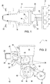
- FIG. 1 Figure 11 shows a top view of a combination of a tractor 10 and a drill 12 attached thereto with a number of row units 14 distributed across the width of the implement 12 for placing seed in the ground, although any other types of seeders 12 may be used.
- the row units 14 may be in line, as shown, or mounted offset from one another in the forward direction.
- the tractor 10 includes a chassis 16 with rear drivable wheels 20 and front, steerable wheels 22.
- Three-point hitch 24 with upper and lower links is a horizontal and transverse to the forward direction of the tractor 10, in the FIG. 1 extending from right to left, extending tool carrier 26 attached.
- the tool holder 26 holds the row units 14 of the drill 12.
- the drill 12 could be attached to the vehicle 12 in any other way, for example, rest on a chassis and pulled over a drawbar. Also, the drill 12 could be designed as a pneumatic seed drill.
- a positioning device 28 based on the reception of satellite signals (GPS, Galileo and / or Glonass and possibly local correction signal) is fastened to the roof of the tractor 10.
- FIG. 2 shows a row unit 14 of the drill 12.
- the attachment of the row unit 14 on the tool carrier 26 via U-shaped brackets 28 which are connected to a console 30 which extends vertically to the back of the tool carrier 26 and on the two superimposed arms 32, 34 are hinged, which are also each hinged to a frame 36 of the row unit 14.
- the links 32, 34 form with the console 30 and the frame 36 an adjustable parallelogram, which defines the height of the frame 36 above the ground.
- pneumatic actuator 38 which is designed in the illustrated embodiment as a pneumatic bellows cylinder engages one hand on top of the console 30 and the other bottom of the lower arm 32 (at point 40) and defines the position of the frame 36 and the pressing force, with which a furrow opener 42 supported on the frame 36 cooperates with the ground.
- the frame 36 carries in known manner a seed hopper 44, a seed tube 46 and a (especially pneumatic, provided by a blower not shown blower) metering device 48, which gradually individual grains of the seed from the seed hopper 44 into the seed tube 46, which deposits it in a furrow, which is produced by the furrow opener 42, whose working depth is predetermined by a Tiefeneinstellrad 50.
- the furrow is closed by a closing wheel 52.
- the vertical position of a rocker 56 supporting the depth adjusting wheel 50, and thus the depth of the furrow in which the seed is deposited, is defined by an actuator 58.
- An unillustrated feedback sensor may detect the current sowing depth.
- a spectrometer assembly 60 is mounted in front of the seed tube 46, which cooperates with the soil 62 and in particular a furrow 42 generated by the furrow opener.
- the spectrometer arrangement 60 optically determines properties of the soil 62, for example with regard to its constituents, and transmits its measured values to a computer 64 of the tractor 10 it, georeferenced using the signals from the position determining device 28, for planning subsequent operations and / or used to control an actuator, such as the actuator 58 for setting the seeding depth.
- the illustrated attachment of the spectrometer assembly 60 is just one embodiment.
- the spectrometer assembly could be mounted on any other (agricultural) machinery and moved across the ground 62 to determine its characteristics.
- the data obtained with regard to the ingredients can be used to control actuators, for example for the application of auxiliaries, such as fertilizers or spraying agents, or to store them in geo-referenced form in order to use them for precision agricultural purposes.
- auxiliaries such as fertilizers or spraying agents
- the spectrometer arrangement 66 embodied as a Raman spectrometer in the illustrated embodiment comprises an electromagnetic wave source 66, which may be a laser diode, transmission means 68, for example in the form of a cylindrical lens, for transmitting the electromagnetic waves from the source 66 directing a wave transmissive window 72 to an illuminated surface 70 on the outside of the window 72 (and hence outside the spectrometer array 60) on a sample 74 to be examined and focusing on the surface 70.
- the electromagnetic waves from the source 66 may be in the visible or (near) infrared region.
- the sample 74 may be, in particular, the ground 62, as in the exemplary embodiment of FIG. 2 or any other biological or geological sample 74.
- the transfer means 68 are shaped such that the illuminated area 70 is in the form of a line, as in FIG FIG. 4 is shown. There may be additional, in the Figures 3 and 4 not shown means (eg lenses, prisms, movable elements o. The like.) Can be used to fan-out of the nearly point-like source 66 outgoing, approximately parallel waves.
- the window 72 may be made of sapphire glass to minimize abrasion by the sample 74. Unlike in the FIG. 3 As shown, the illuminated area 70 may be at a certain distance of a few mm or cm from the window 72.
- the spectrometer arrangement 60 comprises a dispersive element 80 in the form of a grating (or prism) and a detector 84 with detection elements 86 which are incident on it and reflect electromagnetic waves entering the spectrometer arrangement 60 through the window 72 convert electromagnetic waves into electrical signals.
- the grating can be designed as a mirror grating or holographic grating.
- the detector 84 may be implemented as a CCD or photodiode array.
- a lens 76 may be arranged, which forms the diverging waves entering from the sample 74 into parallel waves, and between the dispersive element 80 and the detector 84, a (in particular the dispersive element 80 focusing optics 82 imaging the detector 84).
- a filter 78 can be arranged in front of or behind the dispersive element 80 in order to filter out or attenuate the wavelength of the monochromatic source 66 which interferes with the evaluation of the spectra.
- the lens 76 and focusing optics 82 may be spherical or aspherical lenses or more complex multi-lens assemblies or other optical elements.
- the longitudinal axis of the cylindrical lens serving as transmission means 68 extends transversely to the plane of the FIG. 3 and in the drawing plane the FIG. 4 vertically and thus parallel to the longitudinal direction of the illuminated surface 70.
- the grid gaps of the dispersive element 80 also extend transversely to the plane of the FIG. 3 .
- the optical axes of the lens 76 and the focusing optics 82 lie in the plane of the FIG. 3 ,
- the sample 74 is illuminated after all within a line-shaped surface 70 with monochromatic waves (light).
- the waves reflected by the sample 74 reach the dispersive element 80 and are deflected by the latter in wavelength-dependent directions, ie in the plane of the drawing FIG. 3 dispersed in different angles.
- the detection elements 86 of the detector 84 are received along the plane of the drawing FIG. 3 (which in the context of the present disclosure is referred to as the second direction) have different intensities which depend on the respective wavelength. It is in the superimposed detection elements 86 of FIG. 3 Accordingly, each recorded a spectrum. Due to the line-shaped illuminated surface 74 arise in the transverse to the plane of the FIG. 3 lying direction (which is referred to as the first direction in the context of the present disclosure) on the detector 84 several, independent spectra, each representing different locations of the sample 74.
- the spectrometer arrangement 60 simultaneously acquires the spectra of a plurality of juxtaposed, relatively small regions of the sample 74.
- This makes it possible to achieve a sufficient intensity of the light and, moreover, ensures that in the evaluation of the signals of the detection elements by an evaluation unit, not shown in the figures spatially integrated with the spectrometer array 60 in a housing or it may be separated (eg integrated into the computer device 64 or on a separate computer that can be acted upon by remote data transmission or a portable memory card with the cached signals of the detection elements 86), not representative areas of Sample 74, which can be identified by spectra recorded along the second direction by the detection elements 86, which differ significantly (by more than a threshold value) from the spectra that result in the remaining regions of the sample 74 and may be picked up by the other detection elements 86 of the detector 84 along the second direction, in which evaluation of the ingredients may optionally be discarded, or their adulterating effect on the result is mitigated, at least by averaging.
- the FIG. 5 shows by way of example a spectrum taken by the detector 84 by its detection elements 86 along the second direction (the x-axis is proportional to the wavenumber or 1 / ⁇ ) at which the sample 74 from the source 66 has a monochromatic (here: green) wavelength ⁇ 1 is applied.
- the excitation wavelength ⁇ 1 of the source 66 is filtered out or attenuated by the filter 78 and the spectrum essentially comprises the so-called Stokes scattering excited by the wavelength ⁇ 1 , which is produced by vibrational and rotational modes of surface molecules of the sample 74 being excited Therefore, the waves reflected by the sample 74 are longer wavelength than the wavelength ⁇ 1 and contain less energy due to the energy delivered to the excitation modes of the molecules.
- the FIG. 5 also shows a second spectrum, in which the sample 74 is acted upon by the source 66 with a monochromatic (in this case: red) wavelength ⁇ 2 .
- the excitation wavelength ⁇ 2 of the source 66 is filtered out by the (now different) filter 78, and the spectrum essentially comprises the so-called anti-Stokes scattering excited by the wavelength ⁇ 2 , which results from that of the sample reflected waves absorb additional energy from vibrational and rotational modes of surface molecules of sample 74, and therefore the waves reflected from sample 74 are shorter than wavelength ⁇ 2 and contain more energy due to the energy absorption from the excitation modes of the molecules.
- the wavelength emitted by the source 66 switchable, e.g. to be able to evaluate the Stokes scattering or the anti-Stokes scattering, depending on the application, or normally operate at a first, short-wave wavelength and, in the case of fluorescence, switch over to a longer wavelength which does not produce any fluorescence.
- the source 66 could comprise two or more different electromagnetic wave generators, between which electrical and / or mechanical switching occurs, so that the same area 70 is always applied independently of the wavelength.
- the filter 78 would then also to change, for which a corresponding actuator can be provided, or it is a single filter 78 is used, which filters out or attenuates the two wavelengths of the sources 66 or two filters 78 are arranged one behind the other, one of each one Wavelength of one of the sources 66 filters or attenuates. Narrow-band or edge filters can be used.
- the filter 78 which reduces the intensity of the excitation wavelength by several orders of magnitude, in order to allow a referencing of the wavelength of the source 66 and its intensity for the evaluation of the spectra, attenuates in the range of the respective excitation wavelengths. However, the wavelengths to be examined are transmitted through the filter or filters 78.
- Shorter excitation wavelengths have advantages in Raman spectroscopy, but can not always be used, for example, by the appearance of fluorescence. Longer excitation wavelengths have energy disadvantages, but in some applications they are the only solution to operate Raman spectroscopy.
- the excitation wavelengths of the sources 66 can be placed in particular at the beginning and at the end of the spectral range that can be processed by the spectrometer arrangement 60. When source 66 operates at the shorter wavelength, Stokes scattering is utilized, and when source 66 operates at the longer wavelength, anti-Stokes scattering is utilized. The sources 66 will therefore be alternating and not activated simultaneously.
- the spectral range optimally utilized by the spectrometer is, for example, between approximately 650 nm and approximately 900 nm.
- a source 66 in the form of a semiconductor laser of 660 nm wavelength could serve to excite the Raman spectrum using the Stokes scattering and for the substances of interest in the range 665 nm to 850 nm.
- the second source 66 in the form of a second excitation laser could be at about 900 nm.
- the Raman spectrum from anti-Stokes scattering would then exploit the 895 nm to 700 nm range. Stokes scattering and anti-Stokes scattering have similar but not identical information about the sample. By changing the excitation wavelengths special information can be gained.
- the sources 66 may be operated alternately or there may be (automatically, depending on the spectrum detected) a change in excitation wavelengths, e.g. to prevent any occurring fluorescence.
- the laser wavelength attenuation filters in this embodiment may be edge filters and need not be very narrow band filters (as in the use of multiple orders described below). In addition to the avoidance of fluorescence already mentioned, it can be achieved by skillful choice of the excitation wavelength that the Raman spectrum lies in the most sensitive spectral range of the detection system.
- the dispersive element 80 and the detector 84 as in the FIG. 6 shown, ie the detector 84 detects not only, as usual in the art, the zeroth and first diffraction order, but also the second diffraction order or possibly even higher diffraction orders. With each order, one can optimally use a particular wavelength of the source 66. In addition, the evaluation of the higher orders evaluates the entire information about the sample 74 provided by the detector 84.
- the spectrometer assembly 60 may be mounted in a housing having a first part 90 and a second part 88.
- the second, lower part 88 contains the (in the Figures 3 and 4 shown) optical elements of the spectrometer array 60, including the source 66 and the detector 84 and an associated analog-to-digital converter for digitizing the signals of the detection elements 86 and a memory with identification data and / or specific parameters of the spectrometer array 60, for example by the
- the above-described evaluation unit for evaluating the signals of the detection elements 86 can be used, while the first, upper part 90 for the evaluation of the signals of the detector 84th required evaluation unit, a memory, power supply and an interface to the computer device 64 includes.
- the first part 90 is fixed to the agricultural machine (eg as in FIG. 2 mounted on the frame 36 of the row unit 14 of the drill 12) and is connected by a disconnecting in overload connection in the form of a predetermined breaking point, which can be realized, for example by shear pins 92, with the second part 88.
- a predetermined breaking point which can be realized, for example by shear pins 92.
- the first part 90 could be mounted aboard the farm tractor 10 or higher on the drill 12 and coupled by an electrical connection cable to the second part 88, which in such an embodiment would be supported directly or indirectly on the frame 36 of the drill 12 and would be connected by a splitting in overload connection in the form of a predetermined breaking point with the frame 36.
- a connector of the connecting cable between the two parts 90 and 88 would solve.
- the two-part housing of FIG. 7 can also be used with spectrometer arrangements 60 whose detector 84 comprises only a single row of detection elements 86.
- the entrance and exit angles of the waves on the sample 74 need not, as in the FIG. 3 shown, each about 45 °, but may be different and also be asymmetrical.
- the width of the area 70 in the horizontal plane of the drawing FIG. 3 may be constant or variable by adjusting the transfer means 68, eg to accommodate the particle size of the sample 74.
- the change in the width of the entrance slit can take place in succession or each spectrum or groups of spectra have simultaneously different widths.
Landscapes
- Physics & Mathematics (AREA)
- Life Sciences & Earth Sciences (AREA)
- Spectroscopy & Molecular Physics (AREA)
- General Physics & Mathematics (AREA)
- Health & Medical Sciences (AREA)
- Chemical & Material Sciences (AREA)
- Soil Sciences (AREA)
- Pathology (AREA)
- Immunology (AREA)
- Analytical Chemistry (AREA)
- Biochemistry (AREA)
- General Health & Medical Sciences (AREA)
- Engineering & Computer Science (AREA)
- Environmental Sciences (AREA)
- Wood Science & Technology (AREA)
- Botany (AREA)
- Food Science & Technology (AREA)
- Medicinal Chemistry (AREA)
- Nuclear Medicine, Radiotherapy & Molecular Imaging (AREA)
- Mechanical Engineering (AREA)
- Toxicology (AREA)
- Investigating, Analyzing Materials By Fluorescence Or Luminescence (AREA)
- Investigating Or Analysing Materials By Optical Means (AREA)
Abstract
Eine Spektrometeranordnung (60) zur Untersuchung einer Probe (74) umfasst eine Quelle (66) für elektromagnetische Wellen, Übertragungsmittel (68) zum Übertragen der Wellen zur Probe (74), ein dispersives Element (80) und einen Detektor (84) mit mehreren Nachweiselementen (86) zur Umsetzung der vom dispersiven Element (80) einlaufenden Wellen in elektrische Signale. Die Übertragungsmittel (68) sind ausgelegt, die Probe (74) strichförmig mit den elektromagnetischen Wellen zu beleuchten und die Nachweiselemente (86) des Detektors (84) sind zweidimensional angeordnet.A spectrometer array (60) for inspecting a sample (74) comprises an electromagnetic wave source (66), transmission means (68) for transmitting the waves to the sample (74), a dispersive element (80) and a multiple detector (84) Detection elements (86) for converting the dispersive element (80) incoming waves into electrical signals. The transmission means (68) are adapted to illuminate the sample (74) in lines with the electromagnetic waves and the detection elements (86) of the detector (84) are arranged two-dimensionally.
Description
Die Erfindung betrifft eine Spektrometeranordnung zur Untersuchung einer Probe, umfassend:
- eine Quelle für elektromagnetische Wellen,
- Übertragungsmittel zum Übertragen der Wellen von der Quelle zur Probe,
- ein dispersives Element, das mit von der Probe einlaufenden Wellen beaufschlagbar ist und geeignet ist, die einlaufenden Wellen wellenlängenabhängig in unterschiedliche Richtungen abzulenken, und
- einen Detektor mit mehreren Nachweiselementen zur Umsetzung der vom dispersiven Element einlaufenden Wellen in elektrische Signale, sowie eine damit ausgestattete landwirtschaftliche Maschine.
- a source of electromagnetic waves,
- Transmission means for transmitting the waves from the source to the sample,
- a dispersive element, which is acted upon by the sample incoming waves and is suitable for deflecting the incoming waves wavelength dependent in different directions, and
- a detector having a plurality of detection elements for converting the incoming waves from the dispersive element into electrical signals, as well as an agricultural machine equipped therewith.
Ein Bestreben der Präzisions-Landwirtschaft ist, mit gegebenen Mitteln ein möglichst gutes Ergebnis beim Anbau von Pflanzen zu erzielen. Man versucht daher, beim Säen, Düngen, Spritzen etc. die Arbeitsparameter, wie Sätiefe, Abstände, Saatgutart, Art des Düngemittels, Ausbringmengen etc. zu optimieren, basierend auf zuvor gewonnenen Daten, die vor dem Arbeitsvorgang oder während des Arbeitsvorgangs durch Sensoren oder andere Verfahren ermittelt werden und beispielsweise die Bodenart, Bodenfeuchte und Bodeninhaltsstoffe und/oder die Inhaltsstoffe auszubringender Stoffe (Dünger, Gülle) und/oder Eigenschaften von Pflanzen (Wachstumszustand, Inhaltsstoffe) betreffen.One endeavor of precision agriculture is to achieve the best possible results in the cultivation of plants with the given means. Therefore, when sowing, fertilizing, spraying, etc., one tries to optimize the working parameters, such as sowing depth, spacing, type of seed, type of fertilizer, application rates, etc., based on previously obtained data obtained before or during the operation by sensors or others Determined method and, for example, the soil type, soil moisture and soil ingredients and / or the ingredients auszubringender substances (fertilizer, manure) and / or properties of plants (growth state, ingredients) concern.
Neben chemischen Analysen zur Ermittlung von Inhaltsstoffen des Bodens, z.B. von Phosphor, Kalium oder organischen Inhaltsstoffen wurden sensorbasierte Vorgehensweisen beschrieben, die beispielsweise auf Gammaspektrometern und optischen Spektrometern basieren und bei der Überfahrt über ein Feld anhand von sensorisch erfassten Signalen und daraus abgeleiteten Informationen die Bodeninhaltsstoffe erfassen, um sie zu kartieren und/oder eine Vorrichtung zur Düngemittelausbringung darauf basierend anzusteuern (z.B.
Es wurde zudem vorgeschlagen, Inhaltsstoffe von Böden, insbesondere Phosphor, mit einem Raman-Spektrometer zu untersuchen (
Im Stand der Technik wird bei spektroskopischen Untersuchungen des Bodens oder einer anderen Probe jeweils eine einzige Stelle der Probe mit Licht beaufschlagt. Die Probe setzt sich in der Regel aus relativ kleinen Partikeln zusammen, deren Abmessungen im mm-Bereich oder darunter liegen. Wählt man den Durchmesser des Anregungslichtflecks kleiner als die Partikelgröße, erhält man wegen der Messfläche, die kleiner als die Partikelgröße ist, nicht unbedingt Ergebnisse, die für die gesamte Probe repräsentativ und korrekt wären. Es wäre demnach eine sehr große Anzahl an Messwerten aufzunehmen, um sinnvolle Ergebnisse zu erzielen, was die Messzeit unangemessen lang werden lässt. Alternativ könnte man den Anregungslichtfleck größer als die Partikelgröße wählen, was jedoch den Nachteil mit sich bringt, dass ggf. nicht-repräsentative Partikel (im Falle der Analyse einer Kornprobe z.B. Nichtkornbestandteile) mit analysiert werden, welche das Messergebnis verfälschen. Diese Problematik besteht bei jeder Art von dispersiver Spektroskopie zur Untersuchung von biologischen oder geologischen Proben, d.h. nicht nur bei der Raman-Spektroskopie, sondern auch bei optischer Spektroskopie im (nah-) infraroten oder sichtbaren Wellenlängenbereich, bei welcher die Probe mit breitbandigem Licht bestrahlt und das von der Probe reflektierte oder transmittierte Licht wellenlängenaufgelöst analysiert wird.In the prior art, in spectroscopic examinations of the soil or of another sample, in each case a single point of the sample is exposed to light. The sample is usually composed of relatively small particles whose dimensions are in the mm range or less. If one chooses the diameter of the excitation light spot smaller than the particle size, because of the measuring surface, which is smaller than the particle size, not necessarily results that would be representative and correct for the entire sample. It would therefore take a very large number of readings to achieve meaningful results, which makes the measurement time inappropriately long. Alternatively, one could choose the excitation light spot larger than the particle size, but this has the disadvantage of possibly analyzing non-representative particles (in the case of analysis of a grain sample, for example non-grain constituents), which falsify the measurement result. This problem exists with any type of dispersive spectroscopy for examining biological or geological samples, i. not only in Raman spectroscopy, but also in optical (near infrared) or visible wavelength spectroscopy, in which the sample is irradiated with broadband light and the light reflected or transmitted by the sample is analyzed in a wavelength-resolved manner.
Die Erfindung hat sich zur Aufgabe gesetzt, die genannten Nachteile zu vermeiden oder zumindest zu vermindern.The invention has set itself the task of avoiding the disadvantages mentioned or at least reduce.
Diese Aufgabe wird erfindungsgemäß durch die Lehre der Patentansprüche 1 und 11 gelöst, wobei in den weiteren Patentansprüchen Merkmale aufgeführt sind, die die Lösung in vorteilhafter Weise weiterentwickeln.This object is achieved by the teaching of
Eine Spektrometeranordnung zur Untersuchung einer beliebigen Probe umfasst eine Quelle für elektromagnetische Wellen (z.B. eine oder mehrere Leuchtdiode(n) oder Laserdiode(n)), Übertragungsmittel zum Übertragen der Wellen von der Quelle zur Probe (z.B. eine Linse oder ein Glasfaserkabel), ein dispersives Element (z.B. ein Gitter oder ein Prisma), das mit von der Probe einlaufenden, reflektierten oder transmittierten Wellen beaufschlagbar ist und die einlaufenden Wellen wellenlängenabhängig in unterschiedliche räumliche Richtungen ablenkt, und einen Detektor mit mehreren Nachweiselementen zur Umsetzung der vom dispersiven Element einlaufenden Wellen in elektrische Signale. Die Übertragungsmittel sind ausgelegt, die Probe strichförmig mit den elektromagnetischen Wellen zu beleuchten und die Nachweiselemente des Detektors sind zweidimensional angeordnet.A spectrometer array for examining any sample includes an electromagnetic wave source (eg, one or more light emitting diode (s) or laser diode (s)), transmitting means for transmitting the waves from the source to the sample (eg, a lens or a fiber optic cable), a dispersive Element (eg a grid or a prism), which is acted upon by the sample incoming, reflected or transmitted waves and the incoming waves wavelength-dependent deflected in different spatial directions, and a detector with a plurality of detection elements for converting the incoming of the dispersive element waves in electrical signals. The transmission means are designed to illuminate the sample in lines with the electromagnetic waves and the detection elements of the detector are arranged two-dimensionally.
Auf diese Weise lässt sich erreichen, dass die von unterschiedlichen Orten der strichförmig mit elektromagnetischen Wellen beaufschlagten Probe ausgehenden elektromagnetischen Wellen entlang einer ersten Richtung an unterschiedlichen Nachweiselementen des Detektors und aufgrund der durch das dispersive Element bewirkten, wellenlängenabhängigen Ablenkung entlang einer zweiten Richtung an unterschiedlichen Nachweiselementen des Detektors einlaufen. Die Probe wird somit entlang der strichförmigen Beleuchtung separat spektral analysiert, was die oben erwähnten Probleme vermeidet oder wenigstens mindert.In this way, it is possible to achieve that the electromagnetic waves emanating from different locations of the sample subjected in a line shape to electromagnetic waves along a first direction at different detection elements of the detector and due to the wavelength-dependent deflection effected by the dispersive element along a second direction at different detection elements of the Break in detector. The sample is thus separately spectrally analyzed along the line-shaped illumination, which avoids or at least reduces the above-mentioned problems.
Mit anderen Worten werden die von der Quelle erzeugten, elektromagnetischen Wellen, bei denen es sich um sichtbares Licht oder im darüber oder darunter liegenden Frequenzbereich (UV, (N)IR oder Mikrowellen) liegende Wellen handeln kann, durch die Übertragungsmittel nicht - wie im Stand der Technik - mehr oder weniger kreis- oder punktförmig (sozusagen nulldimensional), sondern strichförmig (eindimensional) auf die Probe projiziert (abgebildet). Hierfür kann beispielsweise eine Zylinderlinse, ein Prisma und/oder ein sich hin- und her bewegendes oder rotierendes Ablenkungs- oder Leitelement für die elektromagnetischen Wellen, z.B. ein Spiegel, verwendet werden. Die Abmessung des beleuchteten Bereichs der Probe quer zur Längsrichtung des Striches kann möglichst klein gewählt werden, um zu erreichen, dass in der Querrichtung möglichst nur ein Partikel der biologischen oder geologischen Probe gleichzeitig illuminiert wird. Die von der Probe reflektierten oder transmittierten Wellen werden durch das dispersive Element in unterschiedliche räumliche Richtungen abgelenkt. Die Nachweiselemente des Detektors sind zweidimensional angeordnet, wobei eine erste Richtung der Längsrichtung des beleuchteten Bereichs der Probe entspricht und die zweite Richtung der Dispersion des dispersiven Elements. Das erfindungsgemäße Spektrometer entspricht somit einer Nebeneinanderanordnung einer beliebig hohen Anzahl von einfachen Spektrometern entlang des beleuchteten Bereichs der Probe, sodass von dem untersuchten Bereich der Probe gleichzeitig eine hohe Anzahl an Spektren gewonnen werden können. Die einzelnen Spektren repräsentieren jeweils relativ kleine Bereiche der Probe, die kleiner als die Partikelgröße der Probe sein können, was die Messgenauigkeit des Spektrometers verbessert und für die gesamte Probe repräsentative Ergebnisse gewährleistet. Zudem besteht die Möglichkeit, nicht-repräsentative Spektren (Ausreißer) von der Auswertung auszunehmen.In other words, the electromagnetic waves generated by the source, which may be visible light or waves lying above or below (UV, (N) IR or microwaves), are not transmitted by the transmission means - as in the prior art The technique - more or less circular or punctiform (so to speak, zero-dimensional), but in a line (one-dimensional) projected onto the sample (shown). For this purpose, for example, a cylindrical lens, a prism and / or a reciprocating or rotating deflection or guide element for the electromagnetic waves, for example a mirror, can be used. The dimension of the illuminated area of the sample transversely to the longitudinal direction of the line can be selected as small as possible in order to achieve that only one particle of the biological or geological sample is simultaneously illuminated in the transverse direction. The waves reflected or transmitted by the sample are deflected by the dispersive element in different spatial directions. The detection elements of the detector are arranged two-dimensionally, wherein a first direction corresponds to the longitudinal direction of the illuminated area of the sample and the second direction corresponds to the dispersion of the dispersive element. The spectrometer according to the invention thus corresponds to a juxtaposition of an arbitrarily high number of simple spectrometers along the illuminated area of the sample, so that a large number of spectra can be obtained simultaneously from the examined area of the sample. The individual spectra each represent relatively small areas of the sample, which may be smaller than the particle size of the sample, which improves the measurement accuracy of the spectrometer and ensures representative results for the entire sample. In addition, it is possible to exclude non-representative spectra (outliers) from the evaluation.
Die Quelle kann die Probe mit breitbandigem Licht beaufschlagen, dessen Spektrum im fern- und/oder nahinfraroten und/oder sichtbaren Wellenlängenbereich liegen kann (vgl.
Weiterhin kann der Detektor mit einer Auswertungseinheit verbunden sein, deren Gehäuse räumlich von einem die Quelle, das Übertragungsmittel, das dispersive Element und den Detektor enthaltenden Gehäuse beabstandet und mit letzterem durch eine sich bei Überlast trennende mechanische und/oder elektrische Verbindung verbunden ist.Furthermore, the detector can be connected to an evaluation unit, the housing of which is spatially separated from a housing containing the source, the transmission means, the dispersive element and the detector and connected to the latter by a mechanical and / or electrical connection which separates when overloaded.
Die Spektrometeranordnung lässt sich stationär oder mobil einsetzen, um eine stationäre Probe zu untersuchen, oder die Probe wird an der Spektrometeranordnung (oder umgekehrt) vorbeigeführt, z.B. auf einem landwirtschaftlichen Feld, um Bodeneigenschaften und insbesondere Inhaltsstoffe des Bodens anhand der ermittelten Spektren zu evaluieren. Sie lässt sich auch zur Untersuchung der Inhaltsstoffe (z.B. Kalium oder Phosphor) von anderen, gasförmigen, festen oder flüssigen Proben (z.B. Gülle, Flüssigdünger, Spritzmitteln, Pflanzen oder Erntegut) einsetzen, sei es als Handgerät oder angebracht an einer Maschine zum Transportieren und/oder Ausbringen der Flüssigkeit oder an einer Erntemaschine. Die ermittelten Inhaltsstoffe und/oder daraus abgeleitete Daten der Probe können durch eine Rechnereinrichtung georeferenziert kartiert und/oder zur Ansteuerung einer landwirtschaftlichen Maschine verwendet werden, z.B. um die Ausbringung von Düngemitteln, Spritzmitteln, Saatgut, Siliermittel etc. zu kontrollieren.The spectrometer assembly can be used stationary or mobile to study a stationary sample, or the sample is passed by the spectrometer assembly (or vice versa), eg on an agricultural field, to evaluate soil properties and in particular soil ingredients from the determined spectra. It can also be used to study the ingredients (eg potassium or phosphorus) of other gaseous, solid or liquid samples (eg manure, liquid fertilizers, sprays, plants or crops), be it as a handheld device or attached to a transporting machine and / or or spreading the liquid or on a harvester. The determined ingredients and / or derived data of the sample can by a Computerized georeferenced maps and / or used to control an agricultural machine, for example, to control the application of fertilizers, sprays, seeds, silage, etc.
In den Zeichnungen ist ein nachfolgend näher beschriebenes Ausführungsbeispiel der Erfindung dargestellt. Es zeigt:
- Fig. 1
- eine Draufsicht auf einen Ackerschlepper mit einer daran angebrachten Sämaschine,
- Fig. 2
- eine seitliche Ansicht einer mit einer Spektrometereinrichtung ausgestatteten Reiheneinheit der Sämaschine,
- Fig. 3
- eine schematische Seitenansicht der Spektrometereinrichtung,
- Fig. 4
- eine Draufsicht auf die Spektrometereinrichtung,
- Fig. 5
- ein Beispiel für von der Spektrometereinrichtung aufgenommene Spektren bei unterschiedlichen Anregungswellenlängen,
- Fig. 6
- ein Schema für unterschiedliche Beugungsordnungen des dispersiven Elements, und
- Fig. 7
- eine schematische, seitliche Ansicht des Gehäuses des Spektrometers mit einem weiteren Gehäuse, in dem eine Auswertungseinheit untergebracht ist.
- Fig. 1
- a top view of an agricultural tractor with an attached seeder,
- Fig. 2
- a side view of a equipped with a spectrometer device row unit of the seeder,
- Fig. 3
- a schematic side view of the spectrometer device,
- Fig. 4
- a plan view of the spectrometer device,
- Fig. 5
- an example of spectra recorded by the spectrometer device at different excitation wavelengths,
- Fig. 6
- a scheme for different diffraction orders of the dispersive element, and
- Fig. 7
- a schematic, side view of the housing of the spectrometer with another housing, in which an evaluation unit is housed.
Die
Die
Das Gestell 36 trägt in an sich bekannter Weise einen Saatgutbehälter 44, ein Saatgutrohr 46 sowie eine (insbesondere pneumatische, mit von einem nicht gezeigten Gebläse bereitgestellten Unterdruck arbeitende) Zumesseinrichtung 48, die nach und nach einzelne Körner des Saatguts aus dem Saatgutbehälter 44 in das Saatgutrohr 46 abgibt, welches es in eine Furche ablegt, die durch den Furchenöffner 42 erzeugt wird, dessen Arbeitstiefe durch ein Tiefeneinstellrad 50 vorgegeben wird. Die Furche wird durch ein Schließrad 52 geschlossen. Die vertikale Position einer das Tiefeneinstellrad 50 halternden Schwinge 56 und somit die Tiefe der Furche, in welcher das Saatgut abgelegt wird, wird durch einen Aktor 58 definiert. Ein nicht gezeigter Rückkopplungssensor kann die aktuelle Sätiefe erfassen.The
Am unteren Ende des Gestells 36 ist vor dem Saatgutrohr 46 eine Spektrometeranordnung 60 angebracht, die mit dem Erdboden 62 und insbesondere einer vom Furchenöffner 42 erzeugten Furche zusammenwirkt. Die Spektrometeranordnung 60 ermittelt auf optische Weise Eigenschaften des Erdbodens 62, z.B. hinsichtlich dessen Inhaltsstoffen, und übermittelt ihre Messwerte an eine Rechnereinrichtung 64 des Ackerschleppers 10. Dort wird sie, unter Verwendung der Signale von der Positionsbestimmungseinrichtung 28, zur Planung nachfolgender Arbeitsvorgänge georeferenziert abgespeichert und/oder dient zur Ansteuerung eines Aktors, z.B. des Aktors 58 zur Vorgabe der Sätiefe. Die dargestellte Anbringung der Spektrometeranordnung 60 ist nur ein Ausführungsbeispiel. Die Spektrometeranordnung könnte an beliebigen anderen (landwirtschaftlichen) Maschinen angebracht werden und von diesen über den Boden 62 bewegt werden, um dessen Eigenschaften zu bestimmen. Auch könnte sie stationär oder mobil eingesetzt werden, um Bodenproben zu untersuchen, oder sie kann zur Analyse der Inhaltsstoffe beliebiger anderer Materialen verwendet werden (z.B. von Gülle oder Fest- oder Flüssig-Dünger oder zu spritzenden oder düngenden Pflanzen oder zu erntendem oder geerntetem Erntegut). Die gewonnenen Daten hinsichtlich der Inhaltsstoffe können zur Ansteuerung von Aktoren z.B. zur Ausbringung von Hilfsstoffen wie Dünger oder Spritzmittel dienen oder georeferenziert abgespeichert werden, um sie zu präzisionslandwirtschaftlichen Zwecken zu nutzen.At the lower end of the
Es wird nun auf die
Das Fenster 72 kann aus Saphirglas sein, um die Abrasion durch die Probe 74 gering zu halten. Anders als in der
Weiterhin umfasst die Spektrometeranordnung 60 zur Analyse von der Probe 74 reflektierten, durch das Fenster 72 wieder in die Spektrometeranordnung 60 eintretenden, elektromagnetischen Wellen ein dispersives Element 80 in Form eines Gitters (oder Prismas) und einen Detektor 84 mit Nachweiselementen 86, die auf sie auftreffende elektromagnetische Wellen in elektrische Signale umsetzen. Das Gitter kann als Spiegelgitter oder holographisches Gitter ausgeführt sein. Der Detektor 84 kann als CCD- oder Photodiodenmatrix ausgeführt sein. Zwischen der Probe 74 und dem dispersiven Element 80 kann eine Linse 76 angeordnet sein, welche die von der Probe 74 einlaufenden, divergierenden Wellen zu parallel verlaufenden Wellen formt, und zwischen dem dispersiven Element 80 und dem Detektor 84 kann eine (insbesondere das dispersive Element 80 auf den Detektor 84 abbildende) Fokussieroptik 82 angebracht sein. Ein Filter 78 kann vor oder hinter dem dispersiven Element 80 angeordnet werden, um die bei der Auswertung der Spektren störende Wellenlänge der monochromatischen Quelle 66 auszufiltern bzw. zu dämpfen. Bei der Linse 76 und der Fokussieroptik 82 kann es sich um sphärische oder asphärische Linsen oder komplexere Mehrlinsenaufbauten oder andere optische Elemente handeln.Furthermore, the
Die Längsachse der als Übertragungsmittel 68 dienenden Zylinderlinse erstreckt sich quer zur Zeichenebene der
Die Probe 74 wird nach alledem innerhalb einer strichförmigen Fläche 70 mit monochromatischen Wellen (Licht) illuminiert. Die von der Probe 74 reflektierten Wellen gelangen zum dispersiven Element 80 und werden durch dieses in wellenlängenabhängigen Richtungen abgelenkt, d.h. in der Zeichenebene der
Die Spektrometeranordnung 60 erfasst demnach gleichzeitig die Spektren mehrerer nebeneinander liegender, relativ kleiner Bereiche der Probe 74. Dadurch wird eine hinreichende Intensität des Lichts ermöglicht und zudem ist sichergestellt, dass bei der Auswertung der Signale der Nachweiselemente durch eine in den Figuren nicht dargestellte Auswertungseinheit, die räumlich mit der Spektrometeranordnung 60 in einem Gehäuse integriert oder davon getrennt sein kann (z.B. in die Rechnereinrichtung 64 integriert oder auf einem separaten Rechner, der durch Datenfernübertragung oder eine transportable Speicherkarte mit den zwischengespeicherten Signalen der Nachweiselemente 86 beaufschlagbar sein kann), nicht repräsentative Bereiche der Probe 74, die sich durch entlang der zweiten Richtung durch die Nachweiselemente 86 aufgenommene Spektren erkennen lassen, die sich signifikant (um mehr als einen Schwellenwert) von den Spektren unterscheiden, die in den übrigen Bereichen der Probe 74 erzeugt und von den anderen Nachweiselementen 86 des Detektors 84 entlang der zweiten Richtung aufgenommen werden, bei der Evaluierung der Inhaltsstoffe ggf. ausgesondert werden können, oder ihre verfälschende Wirkung auf das Ergebnis wird zumindest durch Mittelung gemildert. Es kann eine Mittelung der einzelnen Spektren oder der berechneten Inhaltsstoffe erfolgen, die anhand der einzelnen Spektren und einer Kalibrierung ermittelt werden.Accordingly, the
Die
Die
Es wäre auch möglich, mit einer einzigen Wellenlänge, die zwischen λ1 und λ2 liegt, sowohl die Anti-Stokes-Streuung als auch die Stokes-Streuung anzuregen und zu analysieren.It would also be possible to excite and analyze both anti-Stokes scattering and Stokes scattering with a single wavelength lying between λ 1 and λ 2 .
Es ist demnach denkbar, die von der Quelle 66 abgegebene Wellenlänge umschaltbar zu machen, z.B. um je nach Anwendungsfall die Stokes-Streuung oder die Anti-Stokes-Streuung auswerten zu können oder normalerweise bei einer ersten, kurzwelligen Wellenlänge arbeiten und im Falle von Auftreten von Fluoreszenz auf eine längere Wellenlänge umschalten zu können, die keine Fluoreszenz erzeugt. Dazu könnte die Quelle 66 zwei oder mehr unterschiedliche Erzeuger für elektromagnetische Wellen umfassen, zwischen denen elektrisch und/oder durch mechanische Bewegung umgeschaltet wird, sodass unabhängig von der Wellenlänge stets dieselbe Fläche 70 beaufschlagt wird. Der Filter 78 wäre dann ebenfalls zu wechseln, wozu ein entsprechender Aktor vorgesehen werden kann, oder es wird ein einziger Filter 78 verwendet, der die beiden Wellenlängen der Quellen 66 ausfiltert oder dämpft oder es werden zwei Filter 78 hintereinander angeordnet, von denen jeweils einer eine Wellenlänge einer der Quellen 66 ausfiltert oder dämpft. Es können jeweils schmalbandige oder Kantenfilter verwendet werden. Der Filter 78, welcher die Intensität der Anregungswellenlänge um mehrere Zehnerpotenzen reduziert, um eine Referenzierung der Wellenlänge der Quelle 66 und ihrer Intensität zur Auswertung der Spektren zu ermöglichen, dämpft im Bereich der jeweiligen Anregungswellenlängen. Die zu untersuchenden Wellenlängen werden durch den oder die Filter 78 jedoch durchgelassen.It is therefore conceivable to make the wavelength emitted by the
Kürzere Anregungswellenlängen haben in der Raman-Spektroskopie Vorteile, können aber z.B. durch das Auftreten von Fluoreszenz nicht immer genutzt werden. Längere Anregungswellenlängen haben energetische Nachteile, sind aber in gewissen Anwendungsfällen die einzige Lösung, um Raman-Spektroskopie betreiben zu können. Die Anregungswellenlängen der Quellen 66 können insbesondere an den Anfang und an das Ende des von der Spektrometeranordnung 60 verarbeitbaren Spektralbereiches gelegt werden. Wenn die Quelle 66 mit der kürzeren Wellenlänge arbeitet, wird die Stokes-Streuung genutzt, und wenn die Quelle 66 mit der längeren Wellenlänge arbeitet, wird die Anti-Stokes-Streuung genutzt. Die Quellen 66 werden demnach alternierend und nicht gleichzeitig aktiviert.Shorter excitation wavelengths have advantages in Raman spectroscopy, but can not always be used, for example, by the appearance of fluorescence. Longer excitation wavelengths have energy disadvantages, but in some applications they are the only solution to operate Raman spectroscopy. The excitation wavelengths of the
Der vom Spektrometer optimal ausgenutzte Spektralbereich liege beispielsweise zwischen ca. 650 nm und ca. 900 nm. Eine Quelle 66 in Form eines Halbleiterlasers von 660 nm Wellenlänge könnte zur Anregung des Ramanspektrums dienen, das die Stokes-Streuung benutzt und für die interessierenden Substanzen im Bereich 665 nm bis 850 nm liegt. Die zweite Quelle 66 in Form eines zweiten Anregungslasers könnte bei ca. 900 nm liegen. Das Ramanspektrum aus der Anti-Stokes-Streuung würde dann den Bereich 895 nm bis 700 nm ausnutzen. In der Stokes-Streuung und in der Anti-Stokes-Streuung befinden sich ähnliche aber nicht identische Informationen über die Probe. Durch den Wechsel der Anregungswellenlängen sind spezielle Informationen zu gewinnen. Die Quellen 66 können alternierend betrieben werden oder es erfolgt (automatisiert, abhängig vom detektierten Spektrum) ein Wechsel der Anregungswellenlängen, z.B. um ggf. auftretende Fluoreszenz zu verhindern. Die Filter für die Dämpfung der Laserwellenlänge können bei dieser Ausführungsform Kantenfilter sein und müssen nicht (wie bei der im folgenden Absatz beschriebenen Nutzung von mehreren Ordnungen) sehr schmalbandige Filter sein. Außer der bereits erwähnten Vermeidung von Fluoreszenz kann man durch geschickte Wahl der Anregungswellenlänge erreichen, dass das Ramanspektrum im empfindlichsten Spektralbereich des Detektionssystems liegt.The spectral range optimally utilized by the spectrometer is, for example, between approximately 650 nm and approximately 900 nm. A
Weiterhin wäre denkbar, dass das dispersive Element 80 und der Detektor 84 wie in der
Schließlich ist in der
Man könnte die beiden Teile 90 und 88 auch räumlich weiter voneinander trennen. So könnte der erste Teil 90 an Bord des Ackerschleppers 10 oder weiter oben an der Sämaschine 12 angebracht werden und durch ein elektrisches Verbindungskabel mit dem zweiten Teil 88 gekoppelt werden, der sich bei einer derartigen Ausführungsform direkt oder indirekt am Gestell 36 der Sämaschine 12 abstützen würde und durch eine sich bei Überlast trennende Verbindung in Form einer Sollbruchstelle mit dem Gestell 36 verbunden wäre. In diesem Fall würde sich auch eine Steckverbindung des Verbindungskabels zwischen den beiden Teilen 90 und 88 lösen. Somit wäre auch bei dieser Ausführungsform gewährleistet, dass maximal der zweite Teil 88 zu ersetzen wäre.You could also separate the two
Es sei noch angemerkt, dass das zweiteilige Gehäuse der
Die Ein- und Ausfallswinkel der Wellen auf die Probe 74 müssen nicht, wie in der
Die Breite der Fläche 70 in der horizontalen Zeichenebene der
Claims (11)
Applications Claiming Priority (1)
| Application Number | Priority Date | Filing Date | Title |
|---|---|---|---|
| DE102017213419.4A DE102017213419A1 (en) | 2017-08-02 | 2017-08-02 | spectrometer arrangement |
Publications (2)
| Publication Number | Publication Date |
|---|---|
| EP3437451A1 true EP3437451A1 (en) | 2019-02-06 |
| EP3437451B1 EP3437451B1 (en) | 2020-12-23 |
Family
ID=63077765
Family Applications (1)
| Application Number | Title | Priority Date | Filing Date |
|---|---|---|---|
| EP18185776.4A Active EP3437451B1 (en) | 2017-08-02 | 2018-07-26 | Agricultural machine with a spectrometer assembly |
Country Status (3)
| Country | Link |
|---|---|
| US (1) | US11320369B2 (en) |
| EP (1) | EP3437451B1 (en) |
| DE (1) | DE102017213419A1 (en) |
Cited By (2)
| Publication number | Priority date | Publication date | Assignee | Title |
|---|---|---|---|---|
| DE102020205708A1 (en) | 2020-05-06 | 2021-11-11 | Deere & Company | Sensor arrangement |
| EP4184148A1 (en) | 2021-11-18 | 2023-05-24 | Deere & Company | Sensor assembly |
Families Citing this family (2)
| Publication number | Priority date | Publication date | Assignee | Title |
|---|---|---|---|---|
| US11385379B2 (en) * | 2020-01-23 | 2022-07-12 | Peter J. Wilk | Methods for detecting deposits of known materials |
| DE102020117069A1 (en) * | 2020-06-29 | 2021-12-30 | Claas Selbstfahrende Erntemaschinen Gmbh | Agricultural harvester |
Citations (7)
| Publication number | Priority date | Publication date | Assignee | Title |
|---|---|---|---|---|
| US5038040A (en) * | 1989-09-22 | 1991-08-06 | Agmed Inc. | Soil test apparatus |
| EP1053671A1 (en) | 1999-05-19 | 2000-11-22 | Deere & Company | Measuring device of components in and/or properties of the crop |
| NL1015440C2 (en) | 2000-06-14 | 2001-12-17 | Vma Vlastuin Mest Applicaties | Chemical analysis device for liquid waste products, especially manure, comprises sensor located in outlet for liquid holding vessel |
| US20070013908A1 (en) | 2005-06-28 | 2007-01-18 | Lee Won S | Portable raman sensor for soil nutrient detection |
| WO2014023810A1 (en) * | 2012-08-09 | 2014-02-13 | Georg Fritzmeier Gmbh & Co. Kg | Passive measurement system |
| DE102013208680A1 (en) | 2013-05-13 | 2014-11-13 | Deere & Company | Method for calibrating a gamma spectrometer for detecting soil properties |
| US20160349167A1 (en) * | 2014-05-23 | 2016-12-01 | 7108789 Manitoba Inc. | Coulter Mounted soil Constituent Sensor |
Family Cites Families (12)
| Publication number | Priority date | Publication date | Assignee | Title |
|---|---|---|---|---|
| US5139335A (en) * | 1990-08-24 | 1992-08-18 | Sets, Inc. | Holographic grating imaging spectrometer |
| US5444528A (en) * | 1994-07-27 | 1995-08-22 | The Titan Corporation | Tunable spectrometer with acousto-optical tunable filter |
| US5914779A (en) * | 1997-10-07 | 1999-06-22 | The United States Of America As Represented By The Administrator Of The National Aeronautics And Space Administration | Portable flash lamp reflectance analyzer system and method |
| DE10055905B4 (en) * | 2000-11-13 | 2004-05-13 | Gesellschaft zur Förderung angewandter Optik, Optoelektronik, Quantenelektronik und Spektroskopie e.V. | Method for evaluating Echelle spectra |
| US7342659B2 (en) * | 2005-01-21 | 2008-03-11 | Carl Zeiss Meditec, Inc. | Cross-dispersed spectrometer in a spectral domain optical coherence tomography system |
| GB0701477D0 (en) * | 2007-01-25 | 2007-03-07 | Renishaw Plc | Spectroscopic apparatus and methods |
| JP5718153B2 (en) * | 2011-05-26 | 2015-05-13 | 株式会社トプコン | Plant sensor device |
| GB201113138D0 (en) * | 2011-07-29 | 2011-09-14 | Univ East Anglia | Method, system and device for detecting insects and other pests |
| WO2015006675A2 (en) * | 2013-07-11 | 2015-01-15 | Blue River Technology, Inc. | Method for automatic phenotype measurement and selection |
| GB201415238D0 (en) * | 2014-08-28 | 2014-10-15 | Renishaw Plc | Spectroscopy apparatus |
| JP2016080429A (en) * | 2014-10-14 | 2016-05-16 | 住友電気工業株式会社 | Spectral measurement device |
| WO2017058901A1 (en) * | 2015-09-28 | 2017-04-06 | Ball Aerospace & Technologies Corp. | Differential absorption lidar |
-
2017
- 2017-08-02 DE DE102017213419.4A patent/DE102017213419A1/en not_active Withdrawn
-
2018
- 2018-07-26 EP EP18185776.4A patent/EP3437451B1/en active Active
- 2018-08-02 US US16/053,514 patent/US11320369B2/en active Active
Patent Citations (7)
| Publication number | Priority date | Publication date | Assignee | Title |
|---|---|---|---|---|
| US5038040A (en) * | 1989-09-22 | 1991-08-06 | Agmed Inc. | Soil test apparatus |
| EP1053671A1 (en) | 1999-05-19 | 2000-11-22 | Deere & Company | Measuring device of components in and/or properties of the crop |
| NL1015440C2 (en) | 2000-06-14 | 2001-12-17 | Vma Vlastuin Mest Applicaties | Chemical analysis device for liquid waste products, especially manure, comprises sensor located in outlet for liquid holding vessel |
| US20070013908A1 (en) | 2005-06-28 | 2007-01-18 | Lee Won S | Portable raman sensor for soil nutrient detection |
| WO2014023810A1 (en) * | 2012-08-09 | 2014-02-13 | Georg Fritzmeier Gmbh & Co. Kg | Passive measurement system |
| DE102013208680A1 (en) | 2013-05-13 | 2014-11-13 | Deere & Company | Method for calibrating a gamma spectrometer for detecting soil properties |
| US20160349167A1 (en) * | 2014-05-23 | 2016-12-01 | 7108789 Manitoba Inc. | Coulter Mounted soil Constituent Sensor |
Non-Patent Citations (2)
| Title |
|---|
| J. KRUSE ET AL.: "Innovative methods in soil phosphorus research: A review", J. PLANT NUTR. SOIL SCI., vol. 178, 2015, pages 43 - 88 |
| S. LUNA ET AL.: "Classification of soil samples based on Raman spectroscopy and X-ray fluorescence spectrometry combined with chemometric methods and variable selection", ANAL. METHODS, vol. 6, 2014, pages 8930 - 8939 |
Cited By (3)
| Publication number | Priority date | Publication date | Assignee | Title |
|---|---|---|---|---|
| DE102020205708A1 (en) | 2020-05-06 | 2021-11-11 | Deere & Company | Sensor arrangement |
| EP4184148A1 (en) | 2021-11-18 | 2023-05-24 | Deere & Company | Sensor assembly |
| DE102021130228A1 (en) | 2021-11-18 | 2023-05-25 | Deere & Company | sensor arrangement |
Also Published As
| Publication number | Publication date |
|---|---|
| US20190170640A1 (en) | 2019-06-06 |
| DE102017213419A1 (en) | 2019-02-07 |
| US11320369B2 (en) | 2022-05-03 |
| EP3437451B1 (en) | 2020-12-23 |
Similar Documents
| Publication | Publication Date | Title |
|---|---|---|
| EP3437451B1 (en) | Agricultural machine with a spectrometer assembly | |
| EP3444577B1 (en) | Spectrometric measuring head for gardening, agricultural and food applications | |
| EP2603787B1 (en) | Sensor system and method for determining an optical property of a plant | |
| DE19922867B4 (en) | Harvesting machine with a measuring device for measuring ingredients in and / or properties of crops | |
| EP1523874B1 (en) | Measuring apparatus for measuring components in crop | |
| EP1956361B1 (en) | Measuring device for optical and spectroscopic analysis of a sample | |
| DE102004048103B4 (en) | Spectrometric measuring head for harvesters and other agricultural machines | |
| DE102011085380A1 (en) | Arrangement and method for the prospective investigation of plants to be picked up with a harvester | |
| DE102007032849A1 (en) | Measuring device and method for optical concentration determination of blood sugar and / or lactate in biological systems | |
| DE102008043377A1 (en) | Measuring arrangement for the spectroscopic examination and throughput detection of a crop stream | |
| DE10236515C1 (en) | Crop characteristics measuring method for agricultural harvester compares spectral values provided by NIR or NIT sensor with reference values held in onboard computer | |
| DE10148746C2 (en) | Method and device for the contactless determination and influencing of the plant state | |
| DE10148747A1 (en) | Non-contact monitoring crop and other vegetation condition, for determining fertilizer requirements, uses flash lights for the reflected light to be received by a single photo-diode giving digitized signals for processing | |
| DE102012107319B4 (en) | Passive measuring system | |
| DE19860306A1 (en) | Method and device for the area-specific fertilization of plants | |
| DE10325534B4 (en) | Method for determining fertilizer requirements in gardens, nurseries or parks | |
| DE102017112230A1 (en) | Method and measuring device for determining the deafening coverage of an agricultural area and agricultural distribution machine | |
| DE102022116884A1 (en) | Optical measuring device for spectral analysis of a sample | |
| EP4184148A1 (en) | Sensor assembly | |
| DE102021111827A1 (en) | Sensor arrangement for detecting ingredients | |
| DE10201094B4 (en) | Single-grain analyzer and method for single-grain analysis | |
| DE102020122061A1 (en) | Agricultural working machine | |
| DE102007017482A1 (en) | Spectral area analysis method for determining chlorophyll concentration, involves providing two spectral value functions for analyzing spectral areas by filters, where spectral ranges overlap each other | |
| Capelle et al. | Plant-Stress Measurements Using Laser-Induced Fluorescence Excitation: Poland Experiment | |
| WO2007118458A1 (en) | Spectral analysis method for determining chlorophyll concentration |
Legal Events
| Date | Code | Title | Description |
|---|---|---|---|
| PUAI | Public reference made under article 153(3) epc to a published international application that has entered the european phase |
Free format text: ORIGINAL CODE: 0009012 |
|
| STAA | Information on the status of an ep patent application or granted ep patent |
Free format text: STATUS: THE APPLICATION HAS BEEN PUBLISHED |
|
| AK | Designated contracting states |
Kind code of ref document: A1 Designated state(s): AL AT BE BG CH CY CZ DE DK EE ES FI FR GB GR HR HU IE IS IT LI LT LU LV MC MK MT NL NO PL PT RO RS SE SI SK SM TR |
|
| AX | Request for extension of the european patent |
Extension state: BA ME |
|
| STAA | Information on the status of an ep patent application or granted ep patent |
Free format text: STATUS: REQUEST FOR EXAMINATION WAS MADE |
|
| 17P | Request for examination filed |
Effective date: 20190814 |
|
| RBV | Designated contracting states (corrected) |
Designated state(s): AL AT BE BG CH CY CZ DE DK EE ES FI FR GB GR HR HU IE IS IT LI LT LU LV MC MK MT NL NO PL PT RO RS SE SI SK SM TR |
|
| STAA | Information on the status of an ep patent application or granted ep patent |
Free format text: STATUS: EXAMINATION IS IN PROGRESS |
|
| 17Q | First examination report despatched |
Effective date: 20200403 |
|
| GRAP | Despatch of communication of intention to grant a patent |
Free format text: ORIGINAL CODE: EPIDOSNIGR1 |
|
| STAA | Information on the status of an ep patent application or granted ep patent |
Free format text: STATUS: GRANT OF PATENT IS INTENDED |
|
| RIC1 | Information provided on ipc code assigned before grant |
Ipc: G01N 33/00 20060101ALI20200708BHEP Ipc: G01J 3/02 20060101ALI20200708BHEP Ipc: G01J 3/18 20060101ALI20200708BHEP Ipc: G01N 21/65 20060101ALI20200708BHEP Ipc: G01J 3/44 20060101ALI20200708BHEP Ipc: A01C 21/00 20060101AFI20200708BHEP Ipc: G01N 33/24 20060101ALI20200708BHEP Ipc: A01B 79/00 20060101ALN20200708BHEP |
|
| RIC1 | Information provided on ipc code assigned before grant |
Ipc: A01C 21/00 20060101AFI20200714BHEP Ipc: G01N 33/24 20060101ALI20200714BHEP Ipc: G01N 33/00 20060101ALI20200714BHEP Ipc: A01B 79/00 20060101ALN20200714BHEP Ipc: G01J 3/44 20060101ALI20200714BHEP Ipc: G01N 21/65 20060101ALI20200714BHEP Ipc: G01J 3/18 20060101ALI20200714BHEP Ipc: G01J 3/02 20060101ALI20200714BHEP |
|
| INTG | Intention to grant announced |
Effective date: 20200727 |
|
| GRAS | Grant fee paid |
Free format text: ORIGINAL CODE: EPIDOSNIGR3 |
|
| GRAA | (expected) grant |
Free format text: ORIGINAL CODE: 0009210 |
|
| STAA | Information on the status of an ep patent application or granted ep patent |
Free format text: STATUS: THE PATENT HAS BEEN GRANTED |
|
| AK | Designated contracting states |
Kind code of ref document: B1 Designated state(s): AL AT BE BG CH CY CZ DE DK EE ES FI FR GB GR HR HU IE IS IT LI LT LU LV MC MK MT NL NO PL PT RO RS SE SI SK SM TR |
|
| REG | Reference to a national code |
Ref country code: GB Ref legal event code: FG4D Free format text: NOT ENGLISH |
|
| REG | Reference to a national code |
Ref country code: DE Ref legal event code: R096 Ref document number: 502018003390 Country of ref document: DE |
|
| REG | Reference to a national code |
Ref country code: AT Ref legal event code: REF Ref document number: 1346796 Country of ref document: AT Kind code of ref document: T Effective date: 20210115 |
|
| REG | Reference to a national code |
Ref country code: IE Ref legal event code: FG4D Free format text: LANGUAGE OF EP DOCUMENT: GERMAN |
|
| PG25 | Lapsed in a contracting state [announced via postgrant information from national office to epo] |
Ref country code: GR Free format text: LAPSE BECAUSE OF FAILURE TO SUBMIT A TRANSLATION OF THE DESCRIPTION OR TO PAY THE FEE WITHIN THE PRESCRIBED TIME-LIMIT Effective date: 20210324 Ref country code: NO Free format text: LAPSE BECAUSE OF FAILURE TO SUBMIT A TRANSLATION OF THE DESCRIPTION OR TO PAY THE FEE WITHIN THE PRESCRIBED TIME-LIMIT Effective date: 20210323 Ref country code: FI Free format text: LAPSE BECAUSE OF FAILURE TO SUBMIT A TRANSLATION OF THE DESCRIPTION OR TO PAY THE FEE WITHIN THE PRESCRIBED TIME-LIMIT Effective date: 20201223 Ref country code: RS Free format text: LAPSE BECAUSE OF FAILURE TO SUBMIT A TRANSLATION OF THE DESCRIPTION OR TO PAY THE FEE WITHIN THE PRESCRIBED TIME-LIMIT Effective date: 20201223 |
|
| REG | Reference to a national code |
Ref country code: NL Ref legal event code: MP Effective date: 20201223 |
|
| PG25 | Lapsed in a contracting state [announced via postgrant information from national office to epo] |
Ref country code: BG Free format text: LAPSE BECAUSE OF FAILURE TO SUBMIT A TRANSLATION OF THE DESCRIPTION OR TO PAY THE FEE WITHIN THE PRESCRIBED TIME-LIMIT Effective date: 20210323 Ref country code: SE Free format text: LAPSE BECAUSE OF FAILURE TO SUBMIT A TRANSLATION OF THE DESCRIPTION OR TO PAY THE FEE WITHIN THE PRESCRIBED TIME-LIMIT Effective date: 20201223 Ref country code: LV Free format text: LAPSE BECAUSE OF FAILURE TO SUBMIT A TRANSLATION OF THE DESCRIPTION OR TO PAY THE FEE WITHIN THE PRESCRIBED TIME-LIMIT Effective date: 20201223 |
|
| PG25 | Lapsed in a contracting state [announced via postgrant information from national office to epo] |
Ref country code: NL Free format text: LAPSE BECAUSE OF FAILURE TO SUBMIT A TRANSLATION OF THE DESCRIPTION OR TO PAY THE FEE WITHIN THE PRESCRIBED TIME-LIMIT Effective date: 20201223 Ref country code: HR Free format text: LAPSE BECAUSE OF FAILURE TO SUBMIT A TRANSLATION OF THE DESCRIPTION OR TO PAY THE FEE WITHIN THE PRESCRIBED TIME-LIMIT Effective date: 20201223 |
|
| REG | Reference to a national code |
Ref country code: LT Ref legal event code: MG9D |
|
| PG25 | Lapsed in a contracting state [announced via postgrant information from national office to epo] |
Ref country code: LT Free format text: LAPSE BECAUSE OF FAILURE TO SUBMIT A TRANSLATION OF THE DESCRIPTION OR TO PAY THE FEE WITHIN THE PRESCRIBED TIME-LIMIT Effective date: 20201223 Ref country code: PT Free format text: LAPSE BECAUSE OF FAILURE TO SUBMIT A TRANSLATION OF THE DESCRIPTION OR TO PAY THE FEE WITHIN THE PRESCRIBED TIME-LIMIT Effective date: 20210423 Ref country code: SK Free format text: LAPSE BECAUSE OF FAILURE TO SUBMIT A TRANSLATION OF THE DESCRIPTION OR TO PAY THE FEE WITHIN THE PRESCRIBED TIME-LIMIT Effective date: 20201223 Ref country code: RO Free format text: LAPSE BECAUSE OF FAILURE TO SUBMIT A TRANSLATION OF THE DESCRIPTION OR TO PAY THE FEE WITHIN THE PRESCRIBED TIME-LIMIT Effective date: 20201223 Ref country code: SM Free format text: LAPSE BECAUSE OF FAILURE TO SUBMIT A TRANSLATION OF THE DESCRIPTION OR TO PAY THE FEE WITHIN THE PRESCRIBED TIME-LIMIT Effective date: 20201223 Ref country code: CZ Free format text: LAPSE BECAUSE OF FAILURE TO SUBMIT A TRANSLATION OF THE DESCRIPTION OR TO PAY THE FEE WITHIN THE PRESCRIBED TIME-LIMIT Effective date: 20201223 Ref country code: EE Free format text: LAPSE BECAUSE OF FAILURE TO SUBMIT A TRANSLATION OF THE DESCRIPTION OR TO PAY THE FEE WITHIN THE PRESCRIBED TIME-LIMIT Effective date: 20201223 |
|
| PG25 | Lapsed in a contracting state [announced via postgrant information from national office to epo] |
Ref country code: PL Free format text: LAPSE BECAUSE OF FAILURE TO SUBMIT A TRANSLATION OF THE DESCRIPTION OR TO PAY THE FEE WITHIN THE PRESCRIBED TIME-LIMIT Effective date: 20201223 |
|
| REG | Reference to a national code |
Ref country code: DE Ref legal event code: R097 Ref document number: 502018003390 Country of ref document: DE |
|
| PG25 | Lapsed in a contracting state [announced via postgrant information from national office to epo] |
Ref country code: IS Free format text: LAPSE BECAUSE OF FAILURE TO SUBMIT A TRANSLATION OF THE DESCRIPTION OR TO PAY THE FEE WITHIN THE PRESCRIBED TIME-LIMIT Effective date: 20210423 |
|
| PG25 | Lapsed in a contracting state [announced via postgrant information from national office to epo] |
Ref country code: AL Free format text: LAPSE BECAUSE OF FAILURE TO SUBMIT A TRANSLATION OF THE DESCRIPTION OR TO PAY THE FEE WITHIN THE PRESCRIBED TIME-LIMIT Effective date: 20201223 Ref country code: IT Free format text: LAPSE BECAUSE OF FAILURE TO SUBMIT A TRANSLATION OF THE DESCRIPTION OR TO PAY THE FEE WITHIN THE PRESCRIBED TIME-LIMIT Effective date: 20201223 |
|
| PLBE | No opposition filed within time limit |
Free format text: ORIGINAL CODE: 0009261 |
|
| STAA | Information on the status of an ep patent application or granted ep patent |
Free format text: STATUS: NO OPPOSITION FILED WITHIN TIME LIMIT |
|
| PG25 | Lapsed in a contracting state [announced via postgrant information from national office to epo] |
Ref country code: DK Free format text: LAPSE BECAUSE OF FAILURE TO SUBMIT A TRANSLATION OF THE DESCRIPTION OR TO PAY THE FEE WITHIN THE PRESCRIBED TIME-LIMIT Effective date: 20201223 |
|
| 26N | No opposition filed |
Effective date: 20210924 |
|
| PG25 | Lapsed in a contracting state [announced via postgrant information from national office to epo] |
Ref country code: ES Free format text: LAPSE BECAUSE OF FAILURE TO SUBMIT A TRANSLATION OF THE DESCRIPTION OR TO PAY THE FEE WITHIN THE PRESCRIBED TIME-LIMIT Effective date: 20201223 |
|
| PG25 | Lapsed in a contracting state [announced via postgrant information from national office to epo] |
Ref country code: SI Free format text: LAPSE BECAUSE OF FAILURE TO SUBMIT A TRANSLATION OF THE DESCRIPTION OR TO PAY THE FEE WITHIN THE PRESCRIBED TIME-LIMIT Effective date: 20201223 |
|
| REG | Reference to a national code |
Ref country code: CH Ref legal event code: PL |
|
| PG25 | Lapsed in a contracting state [announced via postgrant information from national office to epo] |
Ref country code: MC Free format text: LAPSE BECAUSE OF FAILURE TO SUBMIT A TRANSLATION OF THE DESCRIPTION OR TO PAY THE FEE WITHIN THE PRESCRIBED TIME-LIMIT Effective date: 20201223 |
|
| REG | Reference to a national code |
Ref country code: BE Ref legal event code: MM Effective date: 20210731 |
|
| PG25 | Lapsed in a contracting state [announced via postgrant information from national office to epo] |
Ref country code: LI Free format text: LAPSE BECAUSE OF NON-PAYMENT OF DUE FEES Effective date: 20210731 Ref country code: CH Free format text: LAPSE BECAUSE OF NON-PAYMENT OF DUE FEES Effective date: 20210731 |
|
| PG25 | Lapsed in a contracting state [announced via postgrant information from national office to epo] |
Ref country code: IS Free format text: LAPSE BECAUSE OF FAILURE TO SUBMIT A TRANSLATION OF THE DESCRIPTION OR TO PAY THE FEE WITHIN THE PRESCRIBED TIME-LIMIT Effective date: 20210423 Ref country code: LU Free format text: LAPSE BECAUSE OF NON-PAYMENT OF DUE FEES Effective date: 20210726 |
|
| PG25 | Lapsed in a contracting state [announced via postgrant information from national office to epo] |
Ref country code: IE Free format text: LAPSE BECAUSE OF NON-PAYMENT OF DUE FEES Effective date: 20210726 Ref country code: BE Free format text: LAPSE BECAUSE OF NON-PAYMENT OF DUE FEES Effective date: 20210731 |
|
| GBPC | Gb: european patent ceased through non-payment of renewal fee |
Effective date: 20220726 |
|
| PG25 | Lapsed in a contracting state [announced via postgrant information from national office to epo] |
Ref country code: GB Free format text: LAPSE BECAUSE OF NON-PAYMENT OF DUE FEES Effective date: 20220726 |
|
| PG25 | Lapsed in a contracting state [announced via postgrant information from national office to epo] |
Ref country code: CY Free format text: LAPSE BECAUSE OF FAILURE TO SUBMIT A TRANSLATION OF THE DESCRIPTION OR TO PAY THE FEE WITHIN THE PRESCRIBED TIME-LIMIT Effective date: 20201223 |
|
| PG25 | Lapsed in a contracting state [announced via postgrant information from national office to epo] |
Ref country code: HU Free format text: LAPSE BECAUSE OF FAILURE TO SUBMIT A TRANSLATION OF THE DESCRIPTION OR TO PAY THE FEE WITHIN THE PRESCRIBED TIME-LIMIT; INVALID AB INITIO Effective date: 20180726 |
|
| PGFP | Annual fee paid to national office [announced via postgrant information from national office to epo] |
Ref country code: FR Payment date: 20230725 Year of fee payment: 6 Ref country code: DE Payment date: 20230621 Year of fee payment: 6 |