EP3437449B1 - Saatfangzunge und säscharanordnung mit der saatfangzunge - Google Patents
Saatfangzunge und säscharanordnung mit der saatfangzunge Download PDFInfo
- Publication number
- EP3437449B1 EP3437449B1 EP18185055.3A EP18185055A EP3437449B1 EP 3437449 B1 EP3437449 B1 EP 3437449B1 EP 18185055 A EP18185055 A EP 18185055A EP 3437449 B1 EP3437449 B1 EP 3437449B1
- Authority
- EP
- European Patent Office
- Prior art keywords
- seed
- tab
- laterally
- furrow
- edge
- Prior art date
- Legal status (The legal status is an assumption and is not a legal conclusion. Google has not performed a legal analysis and makes no representation as to the accuracy of the status listed.)
- Active
Links
Images



Classifications
-
- A—HUMAN NECESSITIES
- A01—AGRICULTURE; FORESTRY; ANIMAL HUSBANDRY; HUNTING; TRAPPING; FISHING
- A01B—SOIL WORKING IN AGRICULTURE OR FORESTRY; PARTS, DETAILS, OR ACCESSORIES OF AGRICULTURAL MACHINES OR IMPLEMENTS, IN GENERAL
- A01B71/00—Construction or arrangement of setting or adjusting mechanisms, of implement or tool drive or of power take-off; Means for protecting parts against dust, or the like; Adapting machine elements to or for agricultural purposes
- A01B71/02—Setting or adjusting mechanisms
-
- A—HUMAN NECESSITIES
- A01—AGRICULTURE; FORESTRY; ANIMAL HUSBANDRY; HUNTING; TRAPPING; FISHING
- A01C—PLANTING; SOWING; FERTILISING
- A01C5/00—Making or covering furrows or holes for sowing, planting or manuring
- A01C5/06—Machines for making or covering drills or furrows for sowing or planting
- A01C5/062—Devices for making drills or furrows
- A01C5/064—Devices for making drills or furrows with rotating tools
-
- A—HUMAN NECESSITIES
- A01—AGRICULTURE; FORESTRY; ANIMAL HUSBANDRY; HUNTING; TRAPPING; FISHING
- A01C—PLANTING; SOWING; FERTILISING
- A01C5/00—Making or covering furrows or holes for sowing, planting or manuring
- A01C5/06—Machines for making or covering drills or furrows for sowing or planting
- A01C5/066—Devices for covering drills or furrows
- A01C5/068—Furrow packing devices, e.g. press wheels
-
- A—HUMAN NECESSITIES
- A01—AGRICULTURE; FORESTRY; ANIMAL HUSBANDRY; HUNTING; TRAPPING; FISHING
- A01C—PLANTING; SOWING; FERTILISING
- A01C7/00—Sowing
- A01C7/20—Parts of seeders for conducting and depositing seed
-
- A—HUMAN NECESSITIES
- A01—AGRICULTURE; FORESTRY; ANIMAL HUSBANDRY; HUNTING; TRAPPING; FISHING
- A01C—PLANTING; SOWING; FERTILISING
- A01C7/00—Sowing
- A01C7/08—Broadcast seeders; Seeders depositing seeds in rows
- A01C7/10—Devices for adjusting the seed-box ; Regulation of machines for depositing quantities at intervals
- A01C7/102—Regulating or controlling the seed rate
- A01C7/105—Seed sensors
Definitions
- the present invention pertains to seeding machines, and in particular to a seed boot assembly having a seed tab.
- Seeding machines such as various singulating and volumetric, air and gravity-fed, seeders may be used for planting seeds. For example, seeds from a supply hopper may be delivered to seed meters associated with individual planting units. Each seed meter may meter seed through a seed tube. A furrow opener of the planting unit may create a seed furrow immediately in front of the end of the seed tube. A seed boot may be attached to the seed tube to direct the seed into the seed furrow, which may be closed by a furrow closing wheel of the planting unit.
- Proper placement of the seeds within the furrow is important to better ensure high crop yield, this includes proper spacing of the seeds within the furrow as well as retention of the seeds within the furrow and proper coverage of the seeds by the ground after the furrow is closed.
- the process of dispensing the seeds may cause the seeds to be displaced from the bottom of the furrow for various reasons, including due to seed bounce in which seeds that have been deposited within the furrow bound out of the furrow after contacting the ground and before the furrow is closed by the trailing closing wheel.
- Flexible seed tabs or flaps have been attached at the outlet ends of the seed boots to act as a deflector to redirect seeds downward and reduce seed loss from seed bounce and the like, see for example EP 3 150 038 A1 .
- a further example is known from US 6 082 275 A disclosing a seed boot assembly (fig. 47) according to the preamble of claim 1.
- seed tabs are prone to wear and breakage from contact with the ground as well as deterioration from UV light.
- the disclosure provides a seed boot assembly for a seeding machine in which an improved seed tab configuration improves seed retention within the furrow formed in the ground.
- the invention is defined by a seed boot assembly according to claim 1.
- lists with elements that are separated by conjunctive terms (e.g., "and") and that are also preceded by the phrase "one or more of” or "at least one of” indicate configurations or arrangements that potentially include individual elements of the list, or any combination thereof.
- “at least one of A, B, and C” or “one or more of A, B, and C” indicates the possibilities of only A, only B, only C, or any combination of two or more of A, B, and C (e.g., A and B; B and C; A and C; or A, B, and C).
- lateral refers to a horizontal dimension generally perpendicular to the fore-aft centerline or center plane of the seeding machine (e.g., towing vehicle and/or planting implement) that generally extends in the travel direction thereof.
- the seeding machine e.g., towing vehicle and/or planting implement
- an “inner” (or “inward") or an “outer” (or “outward") lateral orientation, direction or location As used herein, such terms of spatial relationship may be considered with respect to the centerline of the seeding machine or other reference plane of one or more components thereof (e.g., a given planting unit or component of a planting unit).
- reference to an “inner lateral” orientation, direction or location may be understood to correspond to a lateral side near or adjacent a furrow opening disk of a planting unit.
- Reference to an “outer lateral” orientation, direction or location then will be understood to be the orientation, direction or location that is laterally farther away from the opener disk (i.e., the opposite of the inner or inward orientation, direction or location).
- a seed boot at the end of the seed tube through which seed is metered or otherwise delivered (e.g., singulated or volumetrically) from the planting unit, which may be part of a seeding machine implement towed by an agricultural tractor.
- the seed boot may be located in close proximity to an opener disk or other seed furrow forming assembly so that the seed may be delivered in close proximity to the seed furrow.
- the seed boot may have a seed passage following a rearward and downward path that imparts a rearward and downward trajectory to the seeds with respect to a travel direction of the planting unit.
- the location and configuration of the seed boot may also allow it to aid in maintaining a suitable furrow opening through which the seed may be deposited into the seed furrow.
- the seed passage may contain or be defined by a boot liner, which may a separate component of various configurations (e.g., a flexible tube construction) that aids in unfettered passage of the seeds through the seed boot from the seed tube to the seed furrow.
- the extension member may also be useful to attach an extension member to the seed boot or other part of the planting unit at or near the outlet of the seed passage defined by the seed boot.
- the extension member sometimes referred to as a flap (e.g., a "seed tab” or “seed bounce flap”), may be attached and configured to extend behind the seed passage outlet in a downwardly directed cantilever manner so that its free end will come in contact with the ground when the seed boot is lowered near or into the furrow.
- the seed tab may thus block or deflect back into the furrow seeds that may bounce or otherwise be thrown out of the furrow.
- the seed tab may be rigid, but often the seed tab is flexible to allow it bend or flex upward when contacting the ground to prevent or reduce damage or breakage to the seed tab, the seed boot or other parts of the planting unit.
- the seed tab is formed of a material selected such that the seed tab extends straight when unloaded, but when contacting the ground not only flexes, but also applies a reactive force tending to keep the seed tab in contact with the ground, flexibly yet firmly.
- the seed tabs have a simple linear configuration, such as a straight, square-cornered rectilinear bar stock (i.e., straight, rectangular cross-section).
- seed tabs may undergo significant wear from abrasion due to contact with the ground (and rocks, plants and other materials), particularly at edges (the lateral outer edges) that contacts the walls of the furrows.
- the square corners of such seed tabs may wear down over time to angled surfaces generally corresponding to the tapered furrow walls against which they ride during seeding.
- Other seed tabs have pre-tapered free ends to avoid much of this wear cycle and associated material loss.
- the seed tabs later or initially, generally take the shape of straight bars or tabs with tapered free ends that fit down into, and ride against, the tapered walls of the furrows. Generally, this works to enclose the outer edges of the furrows and tends to block seeds from bouncing out of the furrows.
- the seed boot and seed tab of this disclosure differ from the straight tab or tapered tab configurations of conventional seed tabs.
- the seed tab of this disclosure has a winged tail, or put another way stepped or notched edge configuration, that provides for a laterally widened tail compared to its upper body or the seed boot (especially the internal seed passage thereof) to which the seed tab is mounted typically.
- the seed tab has a free end or tail with a laterally outer edge that extends laterally outward of the laterally outer edge of the tab body. That is, the seed tab has a first laterally outer edge extending proximate an inner surface of the seed passage of the seed boot and a second laterally outer edge that extends laterally outward of the first laterally outer edge.
- the second laterally outer edge also extends laterally outward of the seed passage of the seed boot.
- the stepped, notched or widened area of the seed tab is located to accommodate a laterally outer wall of the seed boot, and in particular, to fill in or enclose an otherwise open area or gap that is near or immediately downstream (in the travel direction) from the seed boot.
- the seed tab extending in this downstream area closes, or effectively closes, such openings or gaps left open by conventional seed tabs and seed boot assemblies, thus improving seed placement and retention within the seed furrow.
- the seed tab defines a laterally extending edge between the laterally outer edge of the tab body and the laterally outer edge of the tab tail.
- the laterally extending edge is disposed proximate an edge surface at the back end of the seed boot.
- the laterally outer edge of the tab body is substantially parallel with some or all of the laterally outer edge of the tab tail. Some or all of the laterally inner and outer edges of the tab body may also be substantially parallel.
- the laterally inner edge of the tab tail may extend laterally outwardly (or narrow) from the laterally inner edge of the tab body.
- the laterally inner edge of the tab tail may taper laterally inward in a straight line from the laterally inner edge of the tab body to its free (or second) end.
- a laterally extending, and generally downwardly facing, edge may extend along the free end between the laterally inner and outer edges of the tab tail.
- a mounting arrangement such as an opening for a threaded fastener, may extend through the tab body for mounting the seed tab to the seed boot or other component of the planting unit.
- example seed boots and seed tabs will be described in detail. It should be understood that other seed boot and/or seed tab configurations may be within the scope of this disclosure, which is thus not to be limited by the illustrated examples described below. Moreover, the example seed boot and seed tab are described with respect to an example planting unit having a volumetric seed meter dispensing seeds under gravity or by forced air, such as is often used to meter small grains, such as wheat, soybeans or the like. However, the seed boot and seed tab of this disclosure may be used with other planting unit assemblies utilizing other seed meters or other seed dispensing mechanisms.
- FIG. 1 depicts an individual planting unit 10 for a seeding machine (not shown).
- the planting unit 10 has a planting unit frame 12 that is coupled to the seeding machine frame (e.g., a rockshaft thereof) by a bar clamp 14.
- the seed is delivered to the planting unit 10 by gravity or pneumatically by a seed tube 18 that extends down from a lower part of the planting unit 10.
- the seed tube 18 in the illustrated example is a plastic or metal tube.
- the planting unit frame 12 may mount a seed meter assembly that may include a mini-hopper holding an accumulated collection of seed from a main seed hopper on the seeding machine or a commodity cart associated with the seeding machine.
- the planting unit frame 12 mounts a single disk furrow opener 20 that may rotate relative to the planting unit frame on a bearing assembly 22, which may be aligned with or angled with respect to the travel direction of the seeding machine.
- the furrow opener 20 is angled with respect to a travel direction D to form a generally V-shaped furrow when the furrow opener 20 cuts into the ground into which the seed is deposited.
- a rotating seed press wheel 24 is mounted to the planting unit frame 12 behind the furrow opener 20 for pressing deposited seeds into the seed furrow.
- a rotating closing wheel 30 mounted to the planting unit frame 12 immediately behind the seed press wheel 24 for collapsing the seed furrow and covering the deposited seeds with a loose layer of soil.
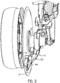
- seed is directed from the seed tube 18 downwardly into a seed boot assembly 40 that is disposed along and to a rear side of the furrow opener 20.
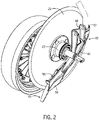
- the seed boot assembly 40 includes a seed boot 42 and a seed tab 44.
- the seed boot 42 may also include a boot liner (not shown), such as flexible tube or other liner material, that may couple directly to the seed tube 18, or indirectly via an adapter piece.
- the seed boot 42 may be a rigid assembled or monolithic component.
- the seed boot 42 may mount to the planting unit frame 12 in any suitable manner, for example, by an integrally formed mounting tab 48, a pivot bolt or pin and a spring to bias the seed boot 42 into the furrow opener 20.
- the seed boot 42 defines a seed passage 50 that has an inlet end 52 and an outlet end 54.
- the inlet end 52 is located in front of the mounting tab 48 and the bearing assembly 22, with respect to the travel direction D of the planting unit 10.
- the outlet end 54 is located below and behind the mounting tab 48 and the bearing assembly 22.
- An integrally formed vane 56 projects downward and rearward from the outlet end 54.
- the vane 56 forms a laterally outer side wall for the outlet end 54 of the seed boot 42.
- the furrow opener 20 is positioned closely to the seed boot 42 and effectively forms a laterally inner side wall for the outlet end 54 of the seed boot 42.
- the seed boot 42 follows a generally straight trajectory from a side perspective, extending downward and rearward at approximately 35-50 degrees, and in some cases about 45 degrees, from horizontal when mounted to the planting unit frame 12, as mentioned, depending on the depth and height setting of the planting unit frame 12 (e.g., the rockshaft) from the ground.
- the seed passage 50 may also have a generally straight, and uniform, cross-section between the inlet end 52 and the outlet end 54. Generally, however, the seed passage 50 is curved to provide adequate clearance between the seed boot 42 and the hub of the furrow opener 20.
- the seed passage 50 has a contoured inner dimension that follows a slightly curved trajectory (e.g., in the laterally outward to inward direction) that is configured to help reduce side to side (i.e., lateral) seed bounce within the seed boot 42, or to otherwise effect seed bounce that causes the seeds to follow a trajectory that expels the seeds in straight lines directly behind the seed boot 42.
- a slightly curved trajectory e.g., in the laterally outward to inward direction
- side to side i.e., lateral
- the seed passage 50 may have a generally circular cross-section at the inlet end 52 and a portion of its length, and have a non-circular cross-sectional through the remainder of its length and at the outlet end 54, transitioning smoothly from the generally circular cross-section to an oblong cross-section which generally has a smaller lateral (sideways) dimension than its height dimension at the outlet end 54.
- the outer surface dimensions and configuration of the seed boot 42 may also vary.
- the seed boot 42 has a compact profile in the lateral dimension compared to certain conventional seed boots, with little to no part of the seed boot 42 extending beyond the laterally inner side of the furrow opener, and may be positioned and configured to skim across the surface of the furrow wall opposite the furrow opener 20. This may reduce wearing of the seed boot 42 and aid in enclosing the seeds deposited from the seed boot 42, in part by reducing boot to soil contact that may tend to widen the top of the furrow inadvertently.
- the seed boot 42 including the vane 56, in combination with the furrow opener 20 and the furrow walls, operates to enclose or confine, or otherwise define, the volume in which seeds may be deposited from the seed boot 42.
- the primary exception to this is the space to the rear (opposite the travel direction D) of the outlet end 54.
- the seed tab 44 serves this function.
- certain prior art seed tabs have a rectangular shape such that the lower square corners contact the low, narrow portion of the V-shaped furrow. This corner contact causes such seed tabs to lift up and away from contact with the furrow, at least until the material of the seed tabs is worn away enough for the seed tab to generally match the furrow shape.
- Such seed tabs may leave open a window between the furrow wall and the seed tab (especially an area "A" under a rear outer corner of the seed boot) on the boot side of the furrow that can allow seeds with a side-to-side trajectory to pass the seed tab high above the furrow bottom in front of the pressing wheel.
- These aspects of prior art seed tabs leave them prone to allowing seeds to bounce up and bypass the seed tab and either escape the furrow or be pressed into the furrow walls above the bottom of the furrow.
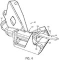
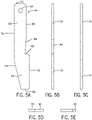
- the seed tab 44 has a tab body 58 with a mounting arrangement 60 at a first end 62, and has a tab tail 64 extending from the tab body 58 to a second end 66.
- the mounting arrangement 60 is an opening extending through the tab body 58 that is sized and configured to receive a mechanical fastener (e.g., a threaded fastener (bolt or screw) 90).
- the tab tail 64 has a laterally outer edge 70 that extends laterally outward of a laterally outer edge 68 of the tab body 58.
- the seed tab 44 may be rigid.
- the seed tab is of flexible construction to bend or flex upwardly when the tab tail 64 contacts the ground with sufficient downward force during operation of the planting unit 10.
- the seed tab 44 may be a thermoplastic polyurethane, a polyethylene or like material, and formed using a suitable injection molding, milling or other operation.
- the seed tab 44 may have material properties or other characteristics that provide desirable flex and downforce values tending to maintain the seed tab 44 in contact with the ground during seeding.
- the seed tab 44 is configured so that, when the tab body 58 is connected to the seed boot 42 at the mounting arrangement 60, the tab tail 64 extends downwardly behind the outlet end 54 of the seed boot 42. As shown, the seed tab 44 is mounted to the back of the seed boot 42 directly above the exit opening at the outlet end 54 of the seed boot 42.
- the profile of the seed tab 44 is configured to better fit within the V-shaped furrow formed by the furrow opener 20.
- an inner edge 74 of the tab tail 64 may contact the furrow wall on the opener (laterally inner) side of the furrow from at or near the bottom of the furrow to where the seed tab 44 contacts the furrow opener 20.
- An inner edge 76 of the tab body 58 may remain in contact with the furrow opener 20 to the mounting arrangement 60 where the seed tab 44 is attached to the seed boot 42.
- the edge 70 of the tab tail 64 may contact the furrow wall from at or near the bottom of the furrow to the underside of the seed boot 42 at a back corner where the outer edge then jogs laterally inward.
- the edge 68 of the tab body 58 may contact a laterally inside wall of the seed boot 42 (e.g., the inside of the vane 56) to the mounting arrangement 60 where the seed tab 44 is attached to the seed boot 42.
- the seed tab 44 has a laterally extending (and slightly upwardly facing) edge 80 that extends between the edge 68 of the tab body 58 and the edge 70 of the tab tail 64.
- the edge 80 extends at an angle (about 90 degrees) with respect to the edge 68 of the tab body 58, thus forming a generally right angle "notch".
- the notch specifically, the lateral edge 80, is disposed proximate an edge surface 82 at the back end of the seed boot 42 (e.g., a rear edge surface of the vane 56) when the seed tab 44 is connected to the seed boot 42.
- the edge 76 of the tab body 58 and the edge 70 of the tab tail 64 may be substantially parallel to the edge 68 of the tab body 58, or at least with a portion of the edge 68. As shown, a portion 84 of the edge 68 of the tab body 58 may be angled (e.g., laterally inward) with respect to the rest of the edge 68 of the tab body 58 and with the edge 70 of the tab tail 64 and the edge 76 of the tab body 58. Thus, the edge surfaces 80 and 84 form a slightly acute angle notch, as shown in FIG. 5A . The edge 76 of the tab body 58 and the edge 74 of the tab tail 64 may be inclined with respect to one another.
- edge 74 of the tab tail 64 may extend laterally outward from the edge 76 of the tab body 58, for example, tapering laterally outward in a straight line from the edge 76 of the tab body 58 to the second end 66 of the tab tail 64.
- Another laterally extending (and slightly downwardly facing) edge 86 extends along the second end 66 between the edges 70 and 74 of the tab tail 64.
- the furrow opener 20 In operation, as the seeding machine, with the planting unit 10, is pulled through a field by a tractor, the furrow opener 20 forms a seed furrow. Seeds passing through the seed tube 18 are directed downward and rearward and exit the outlet end 54 of the seed boot 42 into the seed furrow.
- the furrow may have a relatively small dimension, for example, being only 1,25 cm (0.5 inch) wide by 1,25 - 3,75 cm (0.5 - 1.5 inches) deep, being even more narrow at the bottom of the furrow valley.
- the press wheel 24 fits into the seed furrow and presses the seeds into the bottom of the seed furrow. Since the seed passage 50 is not straight (to provide clearance for furrow opener hub), the seeds must change directions several times as they travel through the seed boot 42.
- the seeds exit the seed boot at a trajectory generally paralleling the center of the seed passage 50 causing them to hit the bottom of the furrow.
- some seeds develop a side-to-side bounce that may cause the seeds to hit the side walls of the furrow or in some cases to be ejected from the furrow.
- the seed tab 44 directs most of these seeds to the bottom of the furrow so that the press wheel 24 can press the seeds into the bottom of the furrow.
- the seed tab 44 is generally oriented to run parallel to the seed passage 50 of the seed boot 42 and extends from the seed boot 42 to at or near the bottom of the furrow.
- the seed tab 44 directs seeds to the bottom of the furrow by completing the enclosure formed by the furrow, the furrow opener 20 and the seed boot 42 by closing off an open space or window immediately downstream from the outlet end 54 of the seed boot 42.
- the wall structure of the seed tab 44 on the side laterally opposite from the furrow opener 20 closes this window.
- the seed boot assembly 40 thus reduces boot wear and seed depth control and placement. A higher percentage of seeds are deposited and pressed in the bottom of the furrow. Wall structure at the outside of the seed tab 44 grazes the furrow wall and better encloses the volume intended for seed deposit. This helps to keep more seeds from bouncing out of the furrow or getting pressed into the sidewall by the closing wheel.
Landscapes
- Life Sciences & Earth Sciences (AREA)
- Soil Sciences (AREA)
- Environmental Sciences (AREA)
- Engineering & Computer Science (AREA)
- Mechanical Engineering (AREA)
- Sowing (AREA)
Claims (7)
- Säscharanordnung (40) mit einer Säschar (42), die einen Saatgutdurchgang (50), der sich von einem Einlassende (52) zu einem Auslassende (54) erstreckt, und eine Saatfangzunge (44), die an dem hinteren Ende der Säschar (42) unmittelbar über der Austrittsöffnung am Auslassende (54) der Säschar (42) montiert ist, aufweist, wobei die Saatfangzunge (44) umfasst:einen Fangzungenkörper (58), der eine Montageanordnung (60) an einem ersten Ende (62) aufweist und einen seitlich äußeren Rand (68, 84) aufweist; undein Fangzungenendteil (64), der sich von dem Fangzungenkörper (58) zu einem zweiten Ende (66) erstreckt, wobei das Fangzungenendteil (64) einen seitlich äußeren Rand (70) aufweist, der sich von dem seitlich äußeren Rand (68, 84) des Fangzungenkörpers (58) seitlich nach außen erstreckt;wobei ein sich seitlich erstreckender Rand (80) sich zwischen dem seitlich äußeren Rand (68, 84) des Fangzungenkörpers (58) und dem seitlich äußeren Rand (70) des Fangzungenendteil (64) erstreckt, wobei der sich seitlich erstreckende Rand (80) nahe an einer Randfläche (82) am hinteren Ende der Säschar (42) angeordnet ist und sich seitlich über die Austrittsöffnung an dem Auslassende (54) der Säschar (42) hinaus erstreckt;wobei der Fangzungenkörper (58) der Saatfangzunge (44) so mit der Säschar (42) verbunden ist, dass der Fangzungenendteil (64) sich hinter dem Auslassende (54) der Säschar (42) nach unten erstreckt;dadurch gekennzeichnet, dassder seitliche äußere Rand (70) des Fangzungenendteils (64) von nahe an dem sich seitlich erstreckenden Rand (80) bis nahe an dem zweiten Ende (66) mit wenigstens einem Teil des seitlich äußeren Rands (68, 84) des Fangzungenkörpers (58) im Wesentlichen parallel ist.
- Säscharanordnung (40) nach Anspruch 1, wobei der Fangzungenkörper (58) einen seitlich inneren Rand (76) aufweist; und
wobei der Fangzungenendteil (64) einen seitlich inneren Rand (74) aufweist. - Säscharanordnung (40) nach Anspruch 2, wobei wenigstens Teile des seitlich inneren (76) und äußeren (68) Rands des Fangzungenkörpers (58) im Wesentlichen parallel sind.
- Säscharanordnung (40) nach Anspruch 2, wobei der seitlich innere Rand (74) des Fangzungenendteils (64) sich von dem seitlich inneren Rand (76) des Fangzungenkörpers (58) seitlich nach außen erstreckt.
- Säscharanordnung (40) nach Anspruch 2, wobei der seitlich innere Rand (74) des Fangzungenendteils (64) von dem seitlich inneren Rand (76) des Fangzungenkörpers (58) in einer Geraden von dem seitlich inneren Rand (76) des Fangzungenkörpers seitlich nach außen zu dem zweiten Ende (66) abgeschrägt ist.
- Säscharanordnung (40) nach Anspruch 2, wobei ein weiterer sich seitlich erstreckender Rand (86) sich an dem zweiten Ende (66) entlang zwischen dem seitlich inneren (74) und äußeren (70) Rand des Fangzungenendteils (64) erstreckt.
- Säscharanordnung (40) nach Anspruch 1, wobei die Befestigungsanordnung (60) eine sich durch den Fangzungenkörper (58) erstreckende Öffnung ist, die zum Aufnehmen eines mit Gewinde versehenen Befestigungselements (90) gestaltet ist.
Applications Claiming Priority (1)
| Application Number | Priority Date | Filing Date | Title |
|---|---|---|---|
| US15/667,174 US10448557B2 (en) | 2017-08-02 | 2017-08-02 | Seed tab and seed boot assembly with seed tab |
Publications (2)
| Publication Number | Publication Date |
|---|---|
| EP3437449A1 EP3437449A1 (de) | 2019-02-06 |
| EP3437449B1 true EP3437449B1 (de) | 2022-04-06 |
Family
ID=63035953
Family Applications (1)
| Application Number | Title | Priority Date | Filing Date |
|---|---|---|---|
| EP18185055.3A Active EP3437449B1 (de) | 2017-08-02 | 2018-07-23 | Saatfangzunge und säscharanordnung mit der saatfangzunge |
Country Status (4)
| Country | Link |
|---|---|
| US (1) | US10448557B2 (de) |
| EP (1) | EP3437449B1 (de) |
| AU (1) | AU2018204139B2 (de) |
| CA (1) | CA3010086A1 (de) |
Families Citing this family (4)
| Publication number | Priority date | Publication date | Assignee | Title |
|---|---|---|---|---|
| CN111386031A (zh) | 2017-10-02 | 2020-07-07 | 精密种植有限责任公司 | 用于土壤和种子监测的系统和设备 |
| FR3079384B1 (fr) * | 2018-04-03 | 2020-06-26 | Kuhn S.A. | Unite d'enfouissement de produit agricole et machine agricole comportant une telle unite |
| BR112022006689A2 (pt) | 2019-12-03 | 2022-07-12 | Prec Planting Llc | Guias de sementes para plantadores |
| US11653586B2 (en) * | 2020-09-02 | 2023-05-23 | Bpr Engineering Pty Ltd | Agricultural ground opener depth adjustment mechanism |
Family Cites Families (9)
| Publication number | Priority date | Publication date | Assignee | Title |
|---|---|---|---|---|
| US5673638A (en) * | 1993-10-15 | 1997-10-07 | J & K Keeton Enterpriseses, Inc. | Resilient seed firming attachment for a planting machine |
| US6082275A (en) * | 1995-10-30 | 2000-07-04 | Schaffert; Paul E. | Extension for reducing seed bounce and associated attachment brackets |
| US6209466B1 (en) | 1999-05-12 | 2001-04-03 | Deere & Company | Two piece seed boot for a seeding machine |
| US6666156B1 (en) * | 2002-08-22 | 2003-12-23 | New Holland North America | Seed flap for controlling seed placement |
| US7168376B2 (en) | 2003-08-01 | 2007-01-30 | Deere & Company | Seed boot for a seeding machine |
| US9703827B2 (en) * | 2014-07-17 | 2017-07-11 | Illumina Consulting Group, Inc. | Methods and apparatus for performing real-time analytics based on multiple types of streamed data |
| US9668402B2 (en) | 2015-01-07 | 2017-06-06 | Matthew P Hagny | Seed bounce flap for agricultural seeder |
| US9402341B1 (en) * | 2015-01-26 | 2016-08-02 | Danny Wipf | Seed firmer |
| US9877425B2 (en) | 2015-10-01 | 2018-01-30 | Deere & Company | Seed boot and liner assembly |
-
2017
- 2017-08-02 US US15/667,174 patent/US10448557B2/en active Active
-
2018
- 2018-06-11 AU AU2018204139A patent/AU2018204139B2/en active Active
- 2018-06-29 CA CA3010086A patent/CA3010086A1/en active Pending
- 2018-07-23 EP EP18185055.3A patent/EP3437449B1/de active Active
Non-Patent Citations (1)
| Title |
|---|
| None * |
Also Published As
| Publication number | Publication date |
|---|---|
| AU2018204139B2 (en) | 2024-09-05 |
| AU2018204139A1 (en) | 2019-02-21 |
| EP3437449A1 (de) | 2019-02-06 |
| US10448557B2 (en) | 2019-10-22 |
| CA3010086A1 (en) | 2019-02-02 |
| US20190037763A1 (en) | 2019-02-07 |
Similar Documents
| Publication | Publication Date | Title |
|---|---|---|
| US7168376B2 (en) | Seed boot for a seeding machine | |
| AU2018204139B2 (en) | Seed Tab and Seed Boot Assembly with Seed Tab | |
| US6209466B1 (en) | Two piece seed boot for a seeding machine | |
| US9668402B2 (en) | Seed bounce flap for agricultural seeder | |
| US7584707B2 (en) | Wear resistant seed tube for an agricultural planter | |
| US7856934B2 (en) | Seed tube and boot for opener assembly of agricultural seeder | |
| US6347594B1 (en) | Narrow profile opener capable of high speed operation | |
| US9820427B2 (en) | Seed tube guard with integral fluid channel for agricultural planters | |
| US5092255A (en) | Seed boot extension | |
| CA1268379A (en) | Air seeder boot | |
| US9456542B2 (en) | Debris assembly for an agricultural row unit | |
| US20150334915A1 (en) | Seed boot mounting | |
| US7464767B2 (en) | Disc opener for an agricultural planting apparatus | |
| CA2788023A1 (en) | Air drill diffuser | |
| EP3150038B1 (de) | Säscharanordnung und pflanzeinheit damit | |
| CA2631473C (en) | Agricultural furrowing tool | |
| US5133270A (en) | Bander assembly for an agricultural implement | |
| US5678500A (en) | Seed delivery device for seed planter | |
| US11109524B2 (en) | Single disk fertilizer opener for an agricultural planter | |
| US12426533B2 (en) | Seed tabs for planters | |
| US20250040471A1 (en) | Seed Meter with Seed Retaining Structure |
Legal Events
| Date | Code | Title | Description |
|---|---|---|---|
| PUAI | Public reference made under article 153(3) epc to a published international application that has entered the european phase |
Free format text: ORIGINAL CODE: 0009012 |
|
| STAA | Information on the status of an ep patent application or granted ep patent |
Free format text: STATUS: THE APPLICATION HAS BEEN PUBLISHED |
|
| AK | Designated contracting states |
Kind code of ref document: A1 Designated state(s): AL AT BE BG CH CY CZ DE DK EE ES FI FR GB GR HR HU IE IS IT LI LT LU LV MC MK MT NL NO PL PT RO RS SE SI SK SM TR |
|
| AX | Request for extension of the european patent |
Extension state: BA ME |
|
| STAA | Information on the status of an ep patent application or granted ep patent |
Free format text: STATUS: REQUEST FOR EXAMINATION WAS MADE |
|
| 17P | Request for examination filed |
Effective date: 20190806 |
|
| RBV | Designated contracting states (corrected) |
Designated state(s): AL AT BE BG CH CY CZ DE DK EE ES FI FR GB GR HR HU IE IS IT LI LT LU LV MC MK MT NL NO PL PT RO RS SE SI SK SM TR |
|
| STAA | Information on the status of an ep patent application or granted ep patent |
Free format text: STATUS: EXAMINATION IS IN PROGRESS |
|
| 17Q | First examination report despatched |
Effective date: 20200603 |
|
| GRAP | Despatch of communication of intention to grant a patent |
Free format text: ORIGINAL CODE: EPIDOSNIGR1 |
|
| STAA | Information on the status of an ep patent application or granted ep patent |
Free format text: STATUS: GRANT OF PATENT IS INTENDED |
|
| INTG | Intention to grant announced |
Effective date: 20211110 |
|
| GRAS | Grant fee paid |
Free format text: ORIGINAL CODE: EPIDOSNIGR3 |
|
| GRAA | (expected) grant |
Free format text: ORIGINAL CODE: 0009210 |
|
| STAA | Information on the status of an ep patent application or granted ep patent |
Free format text: STATUS: THE PATENT HAS BEEN GRANTED |
|
| AK | Designated contracting states |
Kind code of ref document: B1 Designated state(s): AL AT BE BG CH CY CZ DE DK EE ES FI FR GB GR HR HU IE IS IT LI LT LU LV MC MK MT NL NO PL PT RO RS SE SI SK SM TR |
|
| REG | Reference to a national code |
Ref country code: GB Ref legal event code: FG4D |
|
| REG | Reference to a national code |
Ref country code: CH Ref legal event code: EP |
|
| REG | Reference to a national code |
Ref country code: AT Ref legal event code: REF Ref document number: 1480414 Country of ref document: AT Kind code of ref document: T Effective date: 20220415 |
|
| REG | Reference to a national code |
Ref country code: DE Ref legal event code: R096 Ref document number: 602018033245 Country of ref document: DE |
|
| REG | Reference to a national code |
Ref country code: IE Ref legal event code: FG4D |
|
| REG | Reference to a national code |
Ref country code: LT Ref legal event code: MG9D |
|
| REG | Reference to a national code |
Ref country code: NL Ref legal event code: MP Effective date: 20220406 |
|
| REG | Reference to a national code |
Ref country code: AT Ref legal event code: MK05 Ref document number: 1480414 Country of ref document: AT Kind code of ref document: T Effective date: 20220406 |
|
| PG25 | Lapsed in a contracting state [announced via postgrant information from national office to epo] |
Ref country code: NL Free format text: LAPSE BECAUSE OF FAILURE TO SUBMIT A TRANSLATION OF THE DESCRIPTION OR TO PAY THE FEE WITHIN THE PRESCRIBED TIME-LIMIT Effective date: 20220406 |
|
| PG25 | Lapsed in a contracting state [announced via postgrant information from national office to epo] |
Ref country code: SE Free format text: LAPSE BECAUSE OF FAILURE TO SUBMIT A TRANSLATION OF THE DESCRIPTION OR TO PAY THE FEE WITHIN THE PRESCRIBED TIME-LIMIT Effective date: 20220406 Ref country code: PT Free format text: LAPSE BECAUSE OF FAILURE TO SUBMIT A TRANSLATION OF THE DESCRIPTION OR TO PAY THE FEE WITHIN THE PRESCRIBED TIME-LIMIT Effective date: 20220808 Ref country code: NO Free format text: LAPSE BECAUSE OF FAILURE TO SUBMIT A TRANSLATION OF THE DESCRIPTION OR TO PAY THE FEE WITHIN THE PRESCRIBED TIME-LIMIT Effective date: 20220706 Ref country code: LT Free format text: LAPSE BECAUSE OF FAILURE TO SUBMIT A TRANSLATION OF THE DESCRIPTION OR TO PAY THE FEE WITHIN THE PRESCRIBED TIME-LIMIT Effective date: 20220406 Ref country code: HR Free format text: LAPSE BECAUSE OF FAILURE TO SUBMIT A TRANSLATION OF THE DESCRIPTION OR TO PAY THE FEE WITHIN THE PRESCRIBED TIME-LIMIT Effective date: 20220406 Ref country code: GR Free format text: LAPSE BECAUSE OF FAILURE TO SUBMIT A TRANSLATION OF THE DESCRIPTION OR TO PAY THE FEE WITHIN THE PRESCRIBED TIME-LIMIT Effective date: 20220707 Ref country code: FI Free format text: LAPSE BECAUSE OF FAILURE TO SUBMIT A TRANSLATION OF THE DESCRIPTION OR TO PAY THE FEE WITHIN THE PRESCRIBED TIME-LIMIT Effective date: 20220406 Ref country code: ES Free format text: LAPSE BECAUSE OF FAILURE TO SUBMIT A TRANSLATION OF THE DESCRIPTION OR TO PAY THE FEE WITHIN THE PRESCRIBED TIME-LIMIT Effective date: 20220406 Ref country code: BG Free format text: LAPSE BECAUSE OF FAILURE TO SUBMIT A TRANSLATION OF THE DESCRIPTION OR TO PAY THE FEE WITHIN THE PRESCRIBED TIME-LIMIT Effective date: 20220706 Ref country code: AT Free format text: LAPSE BECAUSE OF FAILURE TO SUBMIT A TRANSLATION OF THE DESCRIPTION OR TO PAY THE FEE WITHIN THE PRESCRIBED TIME-LIMIT Effective date: 20220406 |
|
| PG25 | Lapsed in a contracting state [announced via postgrant information from national office to epo] |
Ref country code: RS Free format text: LAPSE BECAUSE OF FAILURE TO SUBMIT A TRANSLATION OF THE DESCRIPTION OR TO PAY THE FEE WITHIN THE PRESCRIBED TIME-LIMIT Effective date: 20220406 Ref country code: PL Free format text: LAPSE BECAUSE OF FAILURE TO SUBMIT A TRANSLATION OF THE DESCRIPTION OR TO PAY THE FEE WITHIN THE PRESCRIBED TIME-LIMIT Effective date: 20220406 Ref country code: LV Free format text: LAPSE BECAUSE OF FAILURE TO SUBMIT A TRANSLATION OF THE DESCRIPTION OR TO PAY THE FEE WITHIN THE PRESCRIBED TIME-LIMIT Effective date: 20220406 Ref country code: IS Free format text: LAPSE BECAUSE OF FAILURE TO SUBMIT A TRANSLATION OF THE DESCRIPTION OR TO PAY THE FEE WITHIN THE PRESCRIBED TIME-LIMIT Effective date: 20220806 |
|
| REG | Reference to a national code |
Ref country code: DE Ref legal event code: R097 Ref document number: 602018033245 Country of ref document: DE |
|
| PG25 | Lapsed in a contracting state [announced via postgrant information from national office to epo] |
Ref country code: SM Free format text: LAPSE BECAUSE OF FAILURE TO SUBMIT A TRANSLATION OF THE DESCRIPTION OR TO PAY THE FEE WITHIN THE PRESCRIBED TIME-LIMIT Effective date: 20220406 Ref country code: SK Free format text: LAPSE BECAUSE OF FAILURE TO SUBMIT A TRANSLATION OF THE DESCRIPTION OR TO PAY THE FEE WITHIN THE PRESCRIBED TIME-LIMIT Effective date: 20220406 Ref country code: RO Free format text: LAPSE BECAUSE OF FAILURE TO SUBMIT A TRANSLATION OF THE DESCRIPTION OR TO PAY THE FEE WITHIN THE PRESCRIBED TIME-LIMIT Effective date: 20220406 Ref country code: EE Free format text: LAPSE BECAUSE OF FAILURE TO SUBMIT A TRANSLATION OF THE DESCRIPTION OR TO PAY THE FEE WITHIN THE PRESCRIBED TIME-LIMIT Effective date: 20220406 Ref country code: DK Free format text: LAPSE BECAUSE OF FAILURE TO SUBMIT A TRANSLATION OF THE DESCRIPTION OR TO PAY THE FEE WITHIN THE PRESCRIBED TIME-LIMIT Effective date: 20220406 Ref country code: CZ Free format text: LAPSE BECAUSE OF FAILURE TO SUBMIT A TRANSLATION OF THE DESCRIPTION OR TO PAY THE FEE WITHIN THE PRESCRIBED TIME-LIMIT Effective date: 20220406 |
|
| PLBE | No opposition filed within time limit |
Free format text: ORIGINAL CODE: 0009261 |
|
| STAA | Information on the status of an ep patent application or granted ep patent |
Free format text: STATUS: NO OPPOSITION FILED WITHIN TIME LIMIT |
|
| PG25 | Lapsed in a contracting state [announced via postgrant information from national office to epo] |
Ref country code: MC Free format text: LAPSE BECAUSE OF FAILURE TO SUBMIT A TRANSLATION OF THE DESCRIPTION OR TO PAY THE FEE WITHIN THE PRESCRIBED TIME-LIMIT Effective date: 20220406 |
|
| REG | Reference to a national code |
Ref country code: CH Ref legal event code: PL |
|
| 26N | No opposition filed |
Effective date: 20230110 |
|
| GBPC | Gb: european patent ceased through non-payment of renewal fee |
Effective date: 20220723 |
|
| REG | Reference to a national code |
Ref country code: BE Ref legal event code: MM Effective date: 20220731 |
|
| PG25 | Lapsed in a contracting state [announced via postgrant information from national office to epo] |
Ref country code: AL Free format text: LAPSE BECAUSE OF FAILURE TO SUBMIT A TRANSLATION OF THE DESCRIPTION OR TO PAY THE FEE WITHIN THE PRESCRIBED TIME-LIMIT Effective date: 20220406 |
|
| PG25 | Lapsed in a contracting state [announced via postgrant information from national office to epo] |
Ref country code: LU Free format text: LAPSE BECAUSE OF NON-PAYMENT OF DUE FEES Effective date: 20220723 Ref country code: LI Free format text: LAPSE BECAUSE OF NON-PAYMENT OF DUE FEES Effective date: 20220731 Ref country code: CH Free format text: LAPSE BECAUSE OF NON-PAYMENT OF DUE FEES Effective date: 20220731 |
|
| PG25 | Lapsed in a contracting state [announced via postgrant information from national office to epo] |
Ref country code: SI Free format text: LAPSE BECAUSE OF FAILURE TO SUBMIT A TRANSLATION OF THE DESCRIPTION OR TO PAY THE FEE WITHIN THE PRESCRIBED TIME-LIMIT Effective date: 20220406 Ref country code: GB Free format text: LAPSE BECAUSE OF NON-PAYMENT OF DUE FEES Effective date: 20220723 Ref country code: BE Free format text: LAPSE BECAUSE OF NON-PAYMENT OF DUE FEES Effective date: 20220731 |
|
| PG25 | Lapsed in a contracting state [announced via postgrant information from national office to epo] |
Ref country code: IE Free format text: LAPSE BECAUSE OF NON-PAYMENT OF DUE FEES Effective date: 20220723 |
|
| PG25 | Lapsed in a contracting state [announced via postgrant information from national office to epo] |
Ref country code: IT Free format text: LAPSE BECAUSE OF FAILURE TO SUBMIT A TRANSLATION OF THE DESCRIPTION OR TO PAY THE FEE WITHIN THE PRESCRIBED TIME-LIMIT Effective date: 20220406 |
|
| PG25 | Lapsed in a contracting state [announced via postgrant information from national office to epo] |
Ref country code: HU Free format text: LAPSE BECAUSE OF FAILURE TO SUBMIT A TRANSLATION OF THE DESCRIPTION OR TO PAY THE FEE WITHIN THE PRESCRIBED TIME-LIMIT; INVALID AB INITIO Effective date: 20180723 |
|
| PG25 | Lapsed in a contracting state [announced via postgrant information from national office to epo] |
Ref country code: MK Free format text: LAPSE BECAUSE OF FAILURE TO SUBMIT A TRANSLATION OF THE DESCRIPTION OR TO PAY THE FEE WITHIN THE PRESCRIBED TIME-LIMIT Effective date: 20220406 Ref country code: CY Free format text: LAPSE BECAUSE OF FAILURE TO SUBMIT A TRANSLATION OF THE DESCRIPTION OR TO PAY THE FEE WITHIN THE PRESCRIBED TIME-LIMIT Effective date: 20220406 |
|
| PG25 | Lapsed in a contracting state [announced via postgrant information from national office to epo] |
Ref country code: MT Free format text: LAPSE BECAUSE OF FAILURE TO SUBMIT A TRANSLATION OF THE DESCRIPTION OR TO PAY THE FEE WITHIN THE PRESCRIBED TIME-LIMIT Effective date: 20220406 |
|
| PG25 | Lapsed in a contracting state [announced via postgrant information from national office to epo] |
Ref country code: BG Free format text: LAPSE BECAUSE OF FAILURE TO SUBMIT A TRANSLATION OF THE DESCRIPTION OR TO PAY THE FEE WITHIN THE PRESCRIBED TIME-LIMIT Effective date: 20220406 |
|
| PG25 | Lapsed in a contracting state [announced via postgrant information from national office to epo] |
Ref country code: BG Free format text: LAPSE BECAUSE OF FAILURE TO SUBMIT A TRANSLATION OF THE DESCRIPTION OR TO PAY THE FEE WITHIN THE PRESCRIBED TIME-LIMIT Effective date: 20220406 |
|
| PGFP | Annual fee paid to national office [announced via postgrant information from national office to epo] |
Ref country code: DE Payment date: 20250620 Year of fee payment: 8 |
|
| PGFP | Annual fee paid to national office [announced via postgrant information from national office to epo] |
Ref country code: FR Payment date: 20250725 Year of fee payment: 8 |
|
| PG25 | Lapsed in a contracting state [announced via postgrant information from national office to epo] |
Ref country code: TR Free format text: LAPSE BECAUSE OF FAILURE TO SUBMIT A TRANSLATION OF THE DESCRIPTION OR TO PAY THE FEE WITHIN THE PRESCRIBED TIME-LIMIT Effective date: 20220406 |