EP3436745B1 - Réacteur à oxygène à combustible liquide assisté par gaz - Google Patents
Réacteur à oxygène à combustible liquide assisté par gaz Download PDFInfo
- Publication number
- EP3436745B1 EP3436745B1 EP17717979.3A EP17717979A EP3436745B1 EP 3436745 B1 EP3436745 B1 EP 3436745B1 EP 17717979 A EP17717979 A EP 17717979A EP 3436745 B1 EP3436745 B1 EP 3436745B1
- Authority
- EP
- European Patent Office
- Prior art keywords
- fuel
- air
- reaction zone
- ion transport
- liquid fuel
- Prior art date
- Legal status (The legal status is an assumption and is not a legal conclusion. Google has not performed a legal analysis and makes no representation as to the accuracy of the status listed.)
- Active
Links
Images


Classifications
-
- F—MECHANICAL ENGINEERING; LIGHTING; HEATING; WEAPONS; BLASTING
- F23—COMBUSTION APPARATUS; COMBUSTION PROCESSES
- F23D—BURNERS
- F23D5/00—Burners in which liquid fuel evaporates in the combustion space, with or without chemical conversion of evaporated fuel
-
- F—MECHANICAL ENGINEERING; LIGHTING; HEATING; WEAPONS; BLASTING
- F23—COMBUSTION APPARATUS; COMBUSTION PROCESSES
- F23D—BURNERS
- F23D11/00—Burners using a direct spraying action of liquid droplets or vaporised liquid into the combustion space
- F23D11/10—Burners using a direct spraying action of liquid droplets or vaporised liquid into the combustion space the spraying being induced by a gaseous medium, e.g. water vapour
-
- F—MECHANICAL ENGINEERING; LIGHTING; HEATING; WEAPONS; BLASTING
- F23—COMBUSTION APPARATUS; COMBUSTION PROCESSES
- F23D—BURNERS
- F23D11/00—Burners using a direct spraying action of liquid droplets or vaporised liquid into the combustion space
- F23D11/36—Details
- F23D11/40—Mixing tubes; Burner heads
- F23D11/404—Flame tubes
-
- F—MECHANICAL ENGINEERING; LIGHTING; HEATING; WEAPONS; BLASTING
- F23—COMBUSTION APPARATUS; COMBUSTION PROCESSES
- F23D—BURNERS
- F23D11/00—Burners using a direct spraying action of liquid droplets or vaporised liquid into the combustion space
- F23D11/36—Details
- F23D11/44—Preheating devices; Vaporising devices
-
- F—MECHANICAL ENGINEERING; LIGHTING; HEATING; WEAPONS; BLASTING
- F23—COMBUSTION APPARATUS; COMBUSTION PROCESSES
- F23D—BURNERS
- F23D23/00—Assemblies of two or more burners
-
- F—MECHANICAL ENGINEERING; LIGHTING; HEATING; WEAPONS; BLASTING
- F23—COMBUSTION APPARATUS; COMBUSTION PROCESSES
- F23D—BURNERS
- F23D3/00—Burners using capillary action
-
- F—MECHANICAL ENGINEERING; LIGHTING; HEATING; WEAPONS; BLASTING
- F23—COMBUSTION APPARATUS; COMBUSTION PROCESSES
- F23D—BURNERS
- F23D5/00—Burners in which liquid fuel evaporates in the combustion space, with or without chemical conversion of evaporated fuel
- F23D5/12—Details
-
- F—MECHANICAL ENGINEERING; LIGHTING; HEATING; WEAPONS; BLASTING
- F23—COMBUSTION APPARATUS; COMBUSTION PROCESSES
- F23N—REGULATING OR CONTROLLING COMBUSTION
- F23N3/00—Regulating air supply or draught
-
- F—MECHANICAL ENGINEERING; LIGHTING; HEATING; WEAPONS; BLASTING
- F23—COMBUSTION APPARATUS; COMBUSTION PROCESSES
- F23D—BURNERS
- F23D2212/00—Burner material specifications
-
- F—MECHANICAL ENGINEERING; LIGHTING; HEATING; WEAPONS; BLASTING
- F23—COMBUSTION APPARATUS; COMBUSTION PROCESSES
- F23D—BURNERS
- F23D2212/00—Burner material specifications
- F23D2212/10—Burner material specifications ceramic
Definitions
- the present disclosure relates to methods and systems for combustion and carbon capture, more particularly, methods and systems involving oxygen transport reactors for the combustion of liquid fuels and the efficient capture of carbon dioxide.
- Fossil fuels remain the main source of energy, particularly in the transportation industry. However, due to the large CO 2 production associated with fossil fuel use, it is also a major contributor to global warming.
- liquid fuels are being widely used in the transportation industry because of their safety and high calorific values. Liquid fuels still produce large amounts of CO 2 , and in order to capture the CO 2 , different techniques are currently available including pre-combustion, post-combustion, and oxyfuel combustion technologies.
- oxyfuel combustion technologies are considered some of the most promising carbon capture technologies.
- oxygen is burnt in a combustion chamber with fuel and the combustion products include only CO 2 and H 2 O.
- the CO 2 and H 2 O can then be separated via a condensation process leaving behind only CO 2 that can be recycled or stored through the sequestration process. This process requires pure oxygen (O 2 ), obtained via cryogenic distillation for example.
- cryogenic distillation process of separation of O 2 from the air is very costly.
- ITMs Ion Transport Membranes
- Oxygen permeation through these membranes is a function of partial pressure of oxygen across the membranes, membrane thickness, and the temperature at which these membranes are operating.
- US2015176487 discloses an oxygen transport reactor for boiler furnaces and gas turbine combustors that utilizes a liquid fuel that is oxidized as a gaseous fuel in a membrane reactor.
- a liquid fuel is introduced by vaporizing the fuel inside a porous pipe surrounded by an annulus reaction zone which is surrounded by an annulus air zone.
- An oxygen transport membrane separates the annulus reaction zone containing the porous vaporized fuel and sweeping CO2 from the air feed side zone.
- Oxygen is transported from the outer annulus through the membrane to the annulus reaction zone containing the vaporized fuel and sweeping CO2.
- Fuel is first cracked to very small droplets in the intake fuel atomizer utilizing part of the intake CO2 then completely vaporized inside the porous pipe utilizing the heat coming from the surrounding reaction zone.
- the oxygen transport reactor is applicable for carbon free boiler furnaces and gas turbine combustors which utilize oxygen transport reactors for combined oxygen separation and combustion.
- a gas-assisted liquid fuel oxygen reactor system according to claims 1 and 7 is provided.
- a method for low-C02 emission combustion of a liquid fuel in a gas-assisted liquid fuel oxygen reactor according to claim 13 is provided. Further developments of the invention can be taken from the dependent claims.
- the present disclosure details systems and methods for a gas-assisted liquid fuel oxygen transport reactor.
- the present application discloses a low-carbon emission oxygen transport reactor for liquid fuel which utilizes gas combustion.
- the present system comprises a gas-assisted (e.g., CO 2 gas) atomizer that provides an atomized spray of liquid fuel and gas into an evaporation zone.
- the atomized fuel and gas is heated in the evaporation zone and then permeates through a fuel filter into a reaction zone (oxygen transport reactor).
- a flow of air (air stream) is also fed into the system in a conduit (vessel) adjacent to the reaction zone. This air stream conduit and the reaction zone are separated by one or more ion transport membranes.
- the oxygen from the air stream permeates through the ion transport membrane and into the reaction zone.
- the combination of the atomized fuel and gas and the permeated oxygen in the reaction zone results in the combustion of the fuel and the production of heat.
- the ion transport membrane operates under low flux, and as such, the rate of heat generated by the reaction zone is relatively low.
- the system of the present application utilizes the stream of atomized gas (e.g., CO 2 ) as a sweep gas to increase the fluxes of oxygen obtained in the reaction zone through the ion transport membrane.
- the present system is a closed-loop control system in which the gas and air streams are recirculated throughout the system to maintain a constant temperature at the ion transport membrane.
- the gas combustion reactions in the reaction zone are used to heat the ion transport membrane(s) to the desired temperature, and the energy required for maintaining the temperature at the ion transport membrane is provided by the partial recirculation of the exhaust gases exiting the reaction zone.
- the now oxygen-depleted air stream can also be used to recirculate heat within the system by providing heat to the liquid fuel via a heat exchanger prior to its entry into the evaporation zone. Maintaining a constant temperature at the ion transport membrane avoids thermal stresses in the ion transport membrane, and thus results in improved membrane stability and thermal performance.
- the systems and methods of the present application allow for efficient self-heating of the system, as well as storage of CO 2 from the exhaust gases, which significantly reduces CO 2 emissions. Further, because the combustion of the fuel is conducted with oxygen rather than air, the system does not result in the emission of NO x .
- FIG. 1 illustrates a cross-sectional view of an exemplary system 100 for a gas-assisted liquid fuel oxygen transport reactor.
- the system 100 has a cylindrical configuration, such as a cylindrical pipe.
- the system can have a planar configuration having horizontal fuel injection slots.
- the system 100 when the system 100 has a cylindrical shape, the system is made up of a series of concentric zones/regions.
- the system 100 can generally be thought to include a first end 102 and an opposing second end 104.
- the cylindrical system 100 includes an evaporation zone 105.
- the evaporation zone includes an inlet 110 for receiving a fuel atomizer 115.
- Liquid fuel is injected into the evaporation zone 105 via the fuel atomizer 115.
- the liquid fuel can comprise one or more compounds including but not limited to methane (CH 4 ), but can also include gaseous fuels and light liquid fuels.
- the fuel atomizer 115 is gas-assisted (e.g., CO 2 -assisted).
- the fuel atomizer 115 can be a liquid fuel pressure atomizer.
- the fuel atomizer 115 can include an inlet 120 for receiving the liquid fuel and an outlet 125 adapted to spray liquid droplets of the atomized fuel and gas (e.g., CO 2 ) into the evaporation zone 105.
- the fuel atomizer 115 thus defines one end of the evaporation zone 105.
- the evaporation zone 105 further includes an outer wall 130 which can have an annular shape as shown.
- the outer wall 130 can comprise one or more (thermal) conductive plates, which can be used to heat the atomized (i.e., liquid droplet) fuel and gas into a vaporized form as will be explained in greater detail below.
- the evaporation zone 105 can further comprise a bluff body 135.
- the bluff body 135 can be used in the evaporation zone to assist in completion of the fuel evaporation and to stabilize the flame.
- the flame is located in the reaction zone 145.
- the bluff body 135 is located downstream of the atomizer 115.
- the vaporized fuel and gas flow across a fuel filter 140 and into a reaction zone (oxygen transport reactor) 145.
- the flow of the CO 2 from the atomizer acts as a sweep gas pushing the atomized fuel through the fuel filter 140 and into the reaction zone 145.
- the fuel filter 140 ensures the removal of unwanted contaminants from the vaporized fuel and gas prior to entry into the reaction zone 145.
- the fuel filter 140 extends across (transverses) the evaporation zone 105 and is thus positioned such that the vaporized fuel and gas from the atomizer flows directly into and through the fuel filter 140.
- the reaction zone 145 is coaxially aligned with the evaporation zone 105 and located downstream thereof. Further, in the embodiment shown in FIG. 1 , the evaporation zone 105 and reaction zone 145 are located in the innermost area (the core) of the cylindrical configuration (e.g., pipe).
- the cylindrical configuration e.g., pipe
- the reaction zone 145 is surrounded by one or more ion transport membranes (ITMs) 150.
- ITMs 150 are made of ceramic materials.
- the ITM 150 has an annular shape with the reaction zone 145 being internal thereto.
- the ITM 150 can comprise a first and a second planar membrane surface, where the reaction zone 145 is disposed between the two planar membrane surfaces.
- Exemplary ITM materials and additional properties of the ITM are disclosed in published paper by Behrouzifar et al. (Experimental Investigation and Mathematical Modeling of Oxygen Permeation Through Dense Ba0.5Sr0.5Co0.8Fe0.2O3- ⁇ (BSCF) Perovskite-type Ceramic Membranes. Ceramics International: 38 (2012); 4797-4811 ).
- BSCF Stimulated Ba0.5Sr0.5Co0.8Fe0.2O3- ⁇
- membrane thickness and temperature can affect oxygen flux across the ITMs. In particular, oxygen flux across the ITM generally increases with increased temperatures around the membrane, as well as with thinner membranes.
- the first conduit 155 Surrounding the one or more ITMs is a first conduit 155 (air vessel).
- the first conduit 155 comprises an inlet (not shown) for an air stream.
- the first conduit 155 can have an annular shape and be concentric with the evaporation and reaction zones.
- the first conduit 155 is defined by ITMs 150 (and in part outer wall 130) and by an outer wall structure described below.
- the mixture of evaporated fuel and sweep gas in the reaction zone 145 induces oxygen from the air stream flowing in the first conduit 155 to transfer across the ITMs 150 into the reaction zone 145.
- the sweep gas e.g., CO 2
- the sweep gas increases the fluxes of oxygen obtained through (across) the ITMs 150, thus inducing oxygen transport from the air stream (in conduit 145) across the ITMs 150.
- the air stream is fed into the system 100 in a counter-flow process in that the air stream flows in the opposite direction of the sweep gas/vaporized fuel.
- This counter flow process provides at least some of the energy required to heat the air stream and thus to maintain uniform temperature along the ITMs, which allows for improved membrane stability.
- the transport of oxygen into the reaction zone 145 results in the combustion of the fuel in the reaction zone 145, thereby resulting in the production of heat.
- an increase in the percentage of fuel (e.g., CH 4 ) in the sweep gas results in increased oxygen permeation through the ITMs 150 as well as increased reaction rates in the reaction zone 145 (See FIGS. 6-7 ).
- the combustion reaction also produces exhausts gases comprising CO 2 and water vapor.
- at least part of the exhaust gases can be recirculated to provide partial heating to the air stream via (thermal) conductive plates 165, providing even greater oxygen flux across the ITMs 150.
- the air stream is heated by radiation from the combustion gases in the reaction zone 145.
- the heated air (oxygen depleted air) exiting 155 is to be circulated into a second conduit 160 to keep the high temperature of the air in 155.
- combustion gases using air and fuel are passed into the second conduit160 as a source of heating to the air in 155.
- the water vapor in the exhausted gases can be condensed leaving essentially only CO 2 in the exhaust gas stream, which can then be stored to reduce CO 2 emissions.
- the gases leaving zone 155 can pass into a condenser (not shown) to condense the water vapor leaving CO 2 that can be compressed and stored.
- the air stream of conduit 155 is heated, which helps to maintain uniform temperature along the ITMs 150 allowing for improved membrane stability.
- the ITMs are maintained at a temperature in the range of approximately 700°C to approximately 900°C. The determination of the preferred temperature depends on an optimization of the high oxygen flux that can be achieved at high temperatures and the constraint of the thermal and mechanical stability of the ITM materials.
- the systems of the present application provide for combustion of fuel using oxygen rather than air, thus resulting in an exhaust stream that is free of nitrogen oxides (NO x ).
- the systems of the present application are zero-NO x emission systems.
- the now oxygen-depleted air stream in first conduit 155 can also be recirculated.
- the energy available in the oxygen-depleted air can be utilized to heat the fuel prior to entry into the evaporation chamber 105 via a heat exchanger, for example (see FIG. 3 ).
- the oxygen-depleted air of conduit 155 can also heat the fuel in the evaporation zone 105 via conductive plates in the outer wall 130.
- the system 100 can also comprise a second conduit 160 (heating vessel) surrounding the first conduit 155, the second conduit 160 and first conduit 155 being separated by at least one (thermal) conductive wall/plate 165.
- the (thermal) conductive wall/plate 165 thus defines both the first conduit 155 and the second conduit 160.
- the (thermal) conductive wall/plate 165 can have an annular shape.
- the second conduit 160 can comprises an inlet (not shown) for a stream of hot air/gaseous fuel stream.
- the hot air/gaseous fuel stream can provide heat to the air stream of the first conduit 155 via the (thermal) conductive walls/plates 165, thereby resulting in better oxygen flux from the air stream across the ITMs 150.
- the cylindrical system 100 further comprises an outer wall 170 which serves as the outer barrier of the second conduit 160 and thus defines the second conduit 160.
- a fluid seal is formed between the outer wall 130 and the ITMs 150. As shown in Fig. 1 , one end of the outer wall 130 abuts and seals against one end of the ITMs 150.
- the system 100 can include a series of flow paths that allow for a series of counter fluid flow. More specifically, in the illustrated embodiment, fluid flow in the evaporation and reaction zones and the second conduit 160 is in the same direction (parallel flow paths) and the fluid flow in the first conduit 155 is in the opposite direction (counter flow path).
- the various zones and flow paths are arranged in a concentric manner due to the fact that in the illustrated embodiment, the system 100 has a cylindrical shape defined at least in part by a series of concentric annular shaped zones/flow paths.
- Fig. 1 system 100
- the system can have a planar configuration such that the ITM 150 can comprise a first and a second planar membrane surface, where the reaction zone 145 is disposed between the two planar membrane surfaces.
- the first conduit 155 air vessel
- the second conduit 160 heatating vessel
- the planar outer wall 170 can be defined by a planar outer wall 170 and the planar conductive plates 165.
- FIG. 2 shows a cross-sectional view of a second embodiment of the gas-assisted liquid fuel oxygen reactor system 200 in a periodic planar configuration having multiple reaction zones in accordance with one or more embodiments. Also, in at least one embodiment, it is possible to use multiple, separated cylindrical systems such as the cylindrical system of Fig. 1 .
- system 200 functions in a similar fashion as the embodiment of FIG. 1 .
- system 200 represents a two stage type system in that there are two sets of the components and flow paths described with reference to Fig. 1 and as described below.
- the system 200 comprises two evaporation zones 205 each having an inlet 210 for receiving an atomizer 215, such as a gas- (e.g., CO 2 ) assisted atomizer.
- an atomizer 215 such as a gas- (e.g., CO 2 ) assisted atomizer.
- the liquid fuel (and CO 2 ) are injected into the atomizers 215 (via inlets 220) and sprayed (via outlets 225) into the evaporation zones 205.
- the fuel and CO 2 are vaporized using heat from (thermal) conductive plates 230.
- each evaporation zone 205 further comprises a bluff body 235.
- the reaction zones 245 are each disposed between ITMs 250. More specifically, in this embodiment, the ITMs 250 can comprise planar membranes, where each reaction zone 245 is disposed between a first and second planar membrane. Bordering the ITMs 250 are air stream conduits 255 (air vessels) having inlets (not shown) for heated air streams.
- each conduit 255 can comprise at least one planar conductive plate 265, which provides heat from the hot air/gaseous fuel stream in conduit 260 to the air stream in conduit 255.
- the ITMs 250 are maintained at a temperature in the range of approximately 700°C to approximately 900°C.
- the system 200 can also comprise air and gaseous fuel conduits 260, which borders the air stream conduits 255, the conduits 260 being separated from conduits 255 by (thermal) conductive walls/plates 265.
- the conduits 260 can each comprise an inlet (not shown) for a stream of hot air/gaseous fuel.
- the hot air/gaseous fuel stream can provide heat to the air stream of conduits 255 via the (thermal) conductive walls/plates 265, thereby resulting in better oxygen flux from the air stream across the ITMs 250.
- the system 200 can further comprises an outer wall 270 which serves as the outer barrier of the conduits 260 comprising the air/gaseous fuel streams. Certain periodic planar embodiments, such as that of FIG. 2 , can provide enhanced efficiency since they avoid energy losses that can sometimes occur through outer wall 170 in a cylindrical configuration.
- the system can comprise several reaction zones (i.e., two or more) each coaxially aligned with its own evaporation zone, and each being disposed between planar ITMs, an air stream conduit, and/or an air plus gaseous fuel conduit.
- Each evaporation zone, ITM (first and second planar membranes), air stream conduit, and air/gaseous fuel conduit (with a reaction zone disposed between the planar membranes) can be thought of as collectively making up a reactor unit, and in certain embodiments, two or more reactor units can be combined, in a stacked orientation for example.
- FIG. 2 displays two reactor units in a stacked orientation.
- the reaction zone is disposed between first and second planar membranes, and the first and second planar membranes are disposed between first and second planar plates of the air vessel (conduit 255).
- a manifold-type structure can be used to create multiple flow paths from a single source.
- a single source of the liquid fuel there can be a single source of the liquid fuel, and a manifold structure can be used to split the liquid stream into multiple flow paths for entry into the multiple evaporation zones 205.
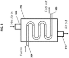
- FIG. 3 shows a heat exchanger 302 for heating of the liquid fuel prior to entry into the evaporation zone, in accordance with one or more embodiments.
- the heat exchanger 302 can be located upstream of the evaporation zone(s). As shown in FIG.
- the heat exchanger 302 can have a first inlet 304 for the fuel, a second inlet 306 for the oxygen-depleted air stream, a first outlet 308 for the fuel, and a second outlet 310 for the oxygen-depleted air stream.
- the second inlet 306 can be connected to the air stream conduit 155 (or 255) for receiving the oxygen-depleted air
- the first outlet 308 can connect to the inlet 120 (220) of the atomizer 115 (or 215).
- the heat from the oxygen-depleted air stream can be transferred to the fuel stream in the heat exchanger 302 in any number of ways known to those of ordinary skill in the art. Further, the exiting oxygen depleted air is generally N 2 rich and can be used in industrial processes such as fertilizer industries.
- the systems of the present application can be self-heating in that they can use the combustion reaction in the reaction zone to heat the ITMs to a desired temperature. Further, the energy provided by the partial recirculation of the exhaust gas stream exiting the reaction zone helps to maintain the ITM temperature.
- the present systems are closed-loop control systems wherein the ITM temperature is maintained at a constant level in order to avoid thermal stresses in the ITM and improve thermal performance.
- each ITM can be one continuous membrane surrounding the reaction zone.
- the ITMs can be a series of ITM tubes. More specifically, in certain embodiments, the ITM tubes can be situated within the reaction zone and perpendicular to the sweep flow (atomized fuel and CO 2 entering the reaction zone) to enhance the oxygen permeation across the ITMs. In other words, in embodiments in which the sweep flow is perpendicular to the ITMs, the ITMs are considered "cross-flow" ITMs, as compared with "coaxial-flow” ITMs in which the sweep flow is parallel to the ITMs.
- FIGS. 4A-B show schematic drawings of the operation of a cross-flow ITM ( FIG. 4A ) compared with the operation of a co-axial flow ITM ( FIG. 4B ).
- FIG. 5 shows a side view of an alternative embodiment of the gas-assisted liquid fuel oxygen reactor having cross-flow ion transport membranes.
- the system 500 can operate in similar fashion as systems 100 and 200, and can comprise all or substantially all of the same elements as shown in the embodiments of FIGS. 1 and 2 , including but not limited to an evaporation zone 505, a fuel filter 540, a reaction zone 545, ITMs 550 (in this embodiment, ITM tubes 550), conductive plates/walls (not shown), and an air plus gaseous fuel stream conduit 560.
- the air stream in system 500 is fed directly into the ITM tubes 550 (as opposed to flowing along an exterior thereof), and oxygen (O 2 ) from the air stream then permeates from inside the ITM tubes 550 to the reaction zone 545 on the outside of the ITM tubes 550 as shown in FIG. 5 .
- the ITM tubes 550 are situated within the reaction zone 545, and the inside of the ITM tubes 550 function as air conduits.
- the reaction zone was located internally within the ITM tube, while in this embodiment, the reaction zone is located external to the ITM tube(s).
- the vaporized fuel and CO 2 stream flows through the fuel filter 540 into the reaction zone 545.
- the flow of the vaporized fuel and CO 2 is a "cross-flow" stream that is perpendicular to the ITM tubes 550.
- the ITM tubes 550 can be vertically oriented from top to bottom in the reaction zone. The cross-flow of the vaporized fuel and CO 2 enhances the oxygen permeation from the air stream through the ITM tubes 550, thereby enhancing the efficiency of the combustion reaction in the reaction zone 545.
- the exhaust gas streams, oxygen-depleted air streams, and the air plus gaseous fuel streams can be recirculated in the system for heating purposes in a similar fashion as described for the embodiments of FIGS. 1 and 2 , including the use of one or more heat exchangers (see FIG. 3 ).
Landscapes
- Engineering & Computer Science (AREA)
- Chemical & Material Sciences (AREA)
- Combustion & Propulsion (AREA)
- Mechanical Engineering (AREA)
- General Engineering & Computer Science (AREA)
- Separation Using Semi-Permeable Membranes (AREA)
- Hydrogen, Water And Hydrids (AREA)
- Physical Or Chemical Processes And Apparatus (AREA)
- Spray-Type Burners (AREA)
- Feeding And Controlling Fuel (AREA)
- Combustion Of Fluid Fuel (AREA)
- Air Supply (AREA)
- Organic Low-Molecular-Weight Compounds And Preparation Thereof (AREA)
Claims (18)
- Système de réacteur d'oxygène à combustible liquide assisté au gaz, comprenant :un atomiseur assisté au CO2 (115, 215) ayant un orifice d'entrée (120, 220) adapté pour recevoir un combustible liquide et un orifice de sortie (125, 225) adapté pour pulvériser du combustible et du CO2 atomisés ;une zone d'évaporation (105, 205) ayant un orifice d'entrée adapté pour recevoir le combustible liquide et le CO2 atomisés et ayant une paroi extérieure (130, 230) qui est formée en un matériau thermiquement conducteur de sorte que la zone d'évaporation (105, 205) est adaptée pour chauffer le combustible et le CO2 atomisés en une forme vaporisée ;une zone de réaction (145, 245) alignée coaxialement sur et en communication fluidique avec la zone d'évaporation (105, 205), dans lequel la zone de réaction (145, 245) est adaptée pour recevoir un écoulement du combustible et du CO2 vaporisés en provenance de la zone d'évaporation (105, 205) ;une membrane de transport d'ions (150, 250) qui est alignée coaxialement sur la zone d'évaporation (105, 205) et définit la zone de réaction (145, 245) ;un réservoir d'air (155, 255) défini par une structure qui est disposée autour de la membrane de transport d'ions (150, 250) et définit un premier espace entre une surface extérieure dans la membrane de transport d'ions et une surface intérieure de la structure de réservoir d'air, dans lequel la structure de réservoir d'air est formée en un matériau thermiquement conducteur et le réservoir d'air (155, 255) sert à recevoir un flux d'air qui s'écoule dans une contre-direction par rapport à un écoulement du combustible et du CO2 vaporisés dans la zone de réaction (145, 245) ; dans lequel la membrane de transport d'ions (150, 250) est adaptée pour fournir de l'O2 par perméation depuis le flux d'air et transférer l'O2 dans la zone de réaction (145, 245) ce qui donne un flux d'air appauvri en O2 dans le premier espace de la structure de réservoir d'air, et dans lequel la zone de réaction (145, 245) est adaptée pour brûler le combustible et le CO2 vaporisés en présence d'O2 pour produire de la chaleur et créer des gaz d'échappement qui sont recirculés dans le système ;caractérisé en ce qu'il comprend :
un réservoir chauffant (160, 260) défini par une structure qui est disposée autour de la structure de réservoir d'air et définit un deuxième espace entre une surface de la structure de réservoir d'air et une surface intérieure de la structure de réservoir chauffant, dans lequel le réservoir chauffant (160, 260) sert à recevoir un flux de combustible gazeux et d'air chauffé de sorte que la chaleur est transférée du flux de combustible gazeux et d'air au premier espace. - Système selon la revendication 1, caractérisé en ce qu'il comprend :un filtre à combustible (140, 240) situé entre la zone d'évaporation (105, 205) et la zone de réaction (145, 245) et adapté pour éliminer des contaminants indésirables du combustible et du CO2 vaporisés avant l'entrée du combustible et du CO2 vaporisés dans la zone de réaction (145, 245) ; etun corps non profilé (135, 235) situé au sein de la zone d'évaporation (105, 205) et adapté pour aider à l'évaporation du combustible.
- Système selon la revendication 1, caractérisé en ce que la recirculation des gaz d'échappement fournit de l'énergie au système pour maintenir une température au moins sensiblement constante au niveau de la membrane de transport d'ions (150, 250), et dans lequel une température au niveau de la membrane de transport d'ions (150, 250) est maintenue entre 700 °C et 900 °C.
- Système selon la revendication 1, caractérisé en ce qu'il comprend :
un échangeur de chaleur (302) situé en amont de l'atomiseur assisté au CO2 (115, 215), l'échangeur de chaleur (302) étant adapté pour recevoir le flux d'air appauvri en O2 en provenance du réservoir d'air (155, 255) et le combustible liquide, et adapté pour transférer de la chaleur du flux d'air appauvri en O2 au combustible liquide avant la réception du combustible liquide dans l'atomiseur assisté au CO2 (115, 215). - Système selon la revendication 1, dans lequel le système a une forme cylindrique, la membrane de transport d'ions (150, 250), la structure de réservoir d'air et la structure de réservoir chauffant étant concentriques l'une par rapport à l'autre, et dans lequel la zone de réaction (145, 245) est située à l'intérieur de la membrane de transport d'ions (150, 250).
- Système selon la revendication 1, caractérisé en ce que la membrane de transport d'ions (150, 250) comprend des première et deuxième membranes planes avec la zone de réaction (145, 245) disposée entre elles, le réservoir d'air (155, 255) comprend des première et deuxième plaques planes (165, 265) avec la membrane de transport d'ions (150, 250) disposée entre elles, et dans lequel la zone d'évaporation (105, 205), la membrane de transport d'ions (150, 250), le réservoir d'air (155, 255), et le réservoir chauffant (160, 260) définissent une première unité de réacteur, et dans lequel le système comporte en outre au moins une deuxième unité de réacteur, la deuxième unité de réacteur ayant une construction identique à la première unité de réacteur, les première et deuxième unités de réacteur étant dans une orientation empilée.
- Système de réacteur d'oxygène à combustible liquide assisté au gaz, comprenant :un atomiseur assisté au CO2 (115, 215) ayant un orifice d'entrée (120, 220) adapté pour recevoir un combustible liquide et un orifice de sortie (125, 225) adapté pour pulvériser le combustible et le CO2 atomisés;une zone d'évaporation (505) ayant un orifice d'entrée adapté pour recevoir le combustible liquide et le CO2 atomisés ;une zone de réaction (545) alignée coaxialement sur et en communication fluidique avec la zone d'évaporation (505) de sorte que la zone de réaction (545) reçoit un écoulement du combustible et du CO2 vaporisés en provenance de la zone d'évaporation (505) ; caractérisé en ce qu'il comprend :une série de tubes (550) composés de membranes de transport situées au sein de la zone de réaction et orientées perpendiculairement à l'écoulement du combustible et du CO2 vaporisés dans la zone de réaction (545), dans lequel les tubes (550) sont adaptés pour recevoir en interne un flux d'air et permettre une perméation d'O2 provenant du flux d'air à travers les membranes de transport d'ions vers la zone de réaction (545) qui entoure les membranes de transport d'ions, ce qui donne ainsi un flux d'air appauvri en O2 à l'intérieur des membranes de transport d'ions et une réaction de combustion dans la zone de réaction (545) qui est située externe aux membranes de transport d'ions, dans lequel la réaction de combustion produit de la chaleur et crée des gaz d'échappement qui sont recirculés dans le système ; etun réservoir chauffant (560) comprenant un orifice d'entrée pour un flux de combustible gazeux et d'air chauffé, dans lequel le réservoir chauffant (560) est défini par une structure qui entoure la zone de réaction (545) de sorte que la chaleur est transférée du flux de combustible gazeux et d'air chauffé à la zone de réaction (545).
- Système selon la revendication 7, caractérisé en ce qu'il comprend :
un filtre à combustible (540) situé entre la zone d'évaporation (505) et la zone de réaction (545) et adapté pour éliminer des contaminants indésirables du combustible et du CO2 vaporisés avant l'entrée du combustible et du CO2 vaporisés dans la zone de réaction (545). - Système selon la revendication 7, caractérisé en ce que la recirculation des gaz d'échappement fournit de l'énergie au système pour maintenir une température constante au niveau de la membrane de transport d'ions, et dans lequel la température au niveau de la membrane de transport d'ions est comprise entre 700 °C et 900 °C.
- Système selon la revendication 7, caractérisé en ce qu'il comprend :
un échangeur de chaleur situé en amont de l'atomiseur assisté au CO2 (115, 215), l'échangeur de chaleur étant adapté pour recevoir le flux d'air appauvri en O2 en provenance des tubes (550) et le combustible liquide, et adapté pour transférer de la chaleur du flux d'air appauvri en O2 au combustible liquide avant la réception du combustible liquide dans l'atomiseur assisté au CO2 (115, 215). - Système selon la revendication 7, caractérisé en ce que le système a une configuration cylindrique, les membranes de transport d'ions s'étendant transversalement à travers le système.
- Système selon la revendication 7, caractérisé en ce que le combustible liquide et le CO2 atomisés et le flux de combustible gazeux et d'air chauffé s'écoulent tous les deux dans la même direction qui est au moins généralement perpendiculaire à l'écoulement du flux d'air.
- Procédé de combustion à faible émission de CO2 d'un combustible liquide dans un réacteur d'oxygène à combustible liquide assisté au gaz, le procédé comprenant :l'injection d'un combustible liquide dans une zone d'évaporation (105, 205), dans lequel le combustible est injecté par le biais d'un atomiseur assisté au CO2 (115, 215) adapté pour pulvériser le combustible liquide et le CO2 dans la zone d'évaporation (105, 205) ;la vaporisation du combustible liquide et du CO2 dans la zone d'évaporation (105, 205), donnant un mélange de combustible et de CO2 évaporés ;l'écoulement du mélange de combustible et de CO2 évaporés dans une zone de réaction (145, 245) qui est coaxiale à la zone d'évaporation (105, 205) ;la fourniture d'un écoulement d'air dans un réservoir d'air (155, 255), dans lequel le réservoir d'air (155, 255) et la zone de réaction (145, 245) sont séparés par une membrane de transport d'ions (150, 250), et dans lequel l'O2 subit une perméation depuis l'écoulement d'air à travers la membrane de transport d'ions (150, 250) et dans la zone de réaction (145, 245) ce qui donne un flux d'air appauvri en O2 dans le réservoir d'air (155, 255) ;la combustion du combustible et du CO2 évaporés en présence d'O2 dans la zone de réaction (145, 245) pour produire de la chaleur et créer un flux de gaz d'échappement et caractérisé en ce qu'il comprend l'étape de :
apport d'un flux de combustible gazeux et d'air chaud dans un réservoir chauffant (160, 260) adjacent au réservoir d'air (155, 255), dans lequel la chaleur provenant du flux du combustible gazeux et d'air chaud est transférée au réservoir d'air (155, 255) via des plaques conductrices (165, 265) séparant le réservoir chauffant (160, 260) et le réservoir d'air (155, 255). - Procédé selon la revendication 13, caractérisé en ce qu'il comprend :
le chauffage du combustible liquide avant injection du combustible liquide dans la zone d'évaporation (105, 205), dans lequel le combustible liquide est chauffé via un échangeur de chaleur (302), et dans lequel l'étape de chauffage du combustible liquide comprend la recirculation du flux d'air appauvri en O2 vers l' échangeur de chaleur (302) en amont de la zone de réaction (145, 245), dans lequel le flux d'air appauvri en O2 recirculé transfère de la chaleur au combustible liquide avant injection du combustible liquide dans l'atomiseur assisté au CO2 (115, 215). - Procédé selon la revendication 13, caractérisé en ce que l'étape de vaporisation du combustible liquide comprend :
le transfert de chaleur du flux de combustible gazeux et d'air chaud à la zone d'évaporation (105, 205) via des plaques conductrices recouvrant une paroi extérieure (130, 230) de la zone d'évaporation (105, 205). - Procédé selon la revendication 13, caractérisé en ce qu'il comprend :
la recirculation du flux de gaz d'échappement pour transférer de la chaleur au réservoir d'air (155, 255), dans lequel la chaleur est transférée au réservoir d'air (155, 255) via une ou plusieurs plaques conductrices (165, 265) recouvrant le réservoir d'air (155, 255). - Procédé selon la revendication 13, caractérisé en ce qu'il comprend :
la filtration du mélange de combustible et de CO2 évaporés avant l'écoulement du mélange dans la zone de réaction (145, 245), dans lequel le combustible et le CO2 évaporés sont filtrés via un filtre à combustible (140, 240). - Procédé selon la revendication 13, caractérisé en ce que le réservoir d'air et la membrane de transport d'ions sont situés au sein de la zone de réaction (145) et dans lequel l'écoulement du mélange de combustible et de CO2 évaporés dans la zone de réaction (145) est perpendiculaire à la membrane de transport d'ions, et en ce que la membrane de transport d'ions est un tube entourant le réservoir d'air.
Applications Claiming Priority (2)
| Application Number | Priority Date | Filing Date | Title |
|---|---|---|---|
| US15/087,300 US10215402B2 (en) | 2016-03-31 | 2016-03-31 | Gas-assisted liguid fuel oxygen reactor |
| PCT/US2017/024984 WO2017173062A1 (fr) | 2016-03-31 | 2017-03-30 | Réacteur à oxygène à combustible liquide assisté par gaz |
Publications (2)
| Publication Number | Publication Date |
|---|---|
| EP3436745A1 EP3436745A1 (fr) | 2019-02-06 |
| EP3436745B1 true EP3436745B1 (fr) | 2020-02-19 |
Family
ID=58548908
Family Applications (1)
| Application Number | Title | Priority Date | Filing Date |
|---|---|---|---|
| EP17717979.3A Active EP3436745B1 (fr) | 2016-03-31 | 2017-03-30 | Réacteur à oxygène à combustible liquide assisté par gaz |
Country Status (8)
| Country | Link |
|---|---|
| US (2) | US10215402B2 (fr) |
| EP (1) | EP3436745B1 (fr) |
| JP (1) | JP6880527B2 (fr) |
| KR (1) | KR102292021B1 (fr) |
| CN (1) | CN109312919B (fr) |
| SA (1) | SA518392203B1 (fr) |
| SG (1) | SG11201807189SA (fr) |
| WO (1) | WO2017173062A1 (fr) |
Families Citing this family (5)
| Publication number | Priority date | Publication date | Assignee | Title |
|---|---|---|---|---|
| CA2490440C (fr) | 2003-12-17 | 2014-02-11 | Cordis Neurovascular, Inc. | Dispositif medical implantable et activable avec mousse extensible et methode d'utilisation |
| US12359807B2 (en) | 2019-12-20 | 2025-07-15 | Jupiter Oxygen Corporation | Combustion system comprising an annular shroud burner |
| US10845052B1 (en) | 2019-12-20 | 2020-11-24 | Jupiter Oxygen Corporation | Combustion system comprising an annular shroud burner |
| CN116829872A (zh) * | 2020-12-21 | 2023-09-29 | 沙特基础工业全球技术公司 | 用于操作加热装置的系统和方法 |
| CN114353058A (zh) * | 2021-12-06 | 2022-04-15 | 浙江京洋环保科技有限公司 | 一种降低燃煤锅炉二氧化碳排放浓度的燃烧方法 |
Family Cites Families (26)
| Publication number | Priority date | Publication date | Assignee | Title |
|---|---|---|---|---|
| AU706663B2 (en) | 1994-09-23 | 1999-06-17 | Standard Oil Company, The | Oxygen permeable mixed conductor membranes |
| US5562754A (en) | 1995-06-07 | 1996-10-08 | Air Products And Chemicals, Inc. | Production of oxygen by ion transport membranes with steam utilization |
| US5820655A (en) | 1997-04-29 | 1998-10-13 | Praxair Technology, Inc. | Solid Electrolyte ionic conductor reactor design |
| US5954859A (en) * | 1997-11-18 | 1999-09-21 | Praxair Technology, Inc. | Solid electrolyte ionic conductor oxygen production with power generation |
| US6153163A (en) | 1998-06-03 | 2000-11-28 | Praxair Technology, Inc. | Ceramic membrane reformer |
| US6375913B1 (en) | 2000-04-10 | 2002-04-23 | Pranair Technology | Integration of ceramic membrane into a silicon oxide production plant |
| US6293084B1 (en) | 2000-05-04 | 2001-09-25 | Praxair Technology, Inc. | Oxygen separator designed to be integrated with a gas turbine and method of separating oxygen |
| EP1197258B1 (fr) | 2000-10-13 | 2010-12-22 | Alstom Technology Ltd | Procédé pour le fonctionnement d'un systeme de production d'energie |
| US6394043B1 (en) | 2000-12-19 | 2002-05-28 | Praxair Technology, Inc. | Oxygen separation and combustion apparatus and method |
| US6562104B2 (en) | 2000-12-19 | 2003-05-13 | Praxair Technology, Inc. | Method and system for combusting a fuel |
| DE10064894A1 (de) | 2000-12-23 | 2002-06-27 | Alstom Switzerland Ltd | Luftzerlegungseinrichtung |
| US6565632B1 (en) | 2001-12-17 | 2003-05-20 | Praxair Technology, Inc. | Ion-transport membrane assembly incorporating internal support |
| US20030223926A1 (en) * | 2002-04-14 | 2003-12-04 | Edlund David J. | Steam reforming fuel processor, burner assembly, and methods of operating the same |
| US7125528B2 (en) | 2002-05-24 | 2006-10-24 | Bp Corporation North America Inc. | Membrane systems containing an oxygen transport membrane and catalyst |
| US7160357B2 (en) | 2003-08-14 | 2007-01-09 | Praxair Technology, Inc. | Oxygen transport membrane reactor and method |
| US7556675B2 (en) | 2005-10-11 | 2009-07-07 | Air Products And Chemicals, Inc. | Feed gas contaminant control in ion transport membrane systems |
| US7384452B2 (en) * | 2005-12-09 | 2008-06-10 | Praxair Technology, Inc. | Fluid heating method |
| KR102046773B1 (ko) * | 2009-04-06 | 2019-11-20 | 24엠 테크놀러지스 인코퍼레이티드 | 산화환원 흐름 배터리를 사용하는 연료 시스템 |
| US8820312B2 (en) | 2011-12-06 | 2014-09-02 | King Fahd University Of Petroleum And Minerals | Oxygen transport reactor-based oven |
| US9004909B2 (en) * | 2012-02-03 | 2015-04-14 | Massachusetts Institute Of Technology | Integrated polymeric-ceramic membrane based oxy-fuel combustor |
| US20140174329A1 (en) | 2012-12-26 | 2014-06-26 | King Fahd University Of Petroleum And Minerals | Controlled temperature ion transport membrane reactor |
| US9383096B2 (en) | 2013-12-23 | 2016-07-05 | King Fahd University Of Petroleum And Minerals | Carbon-free low-NOx liquid fuel oxygen transport reactor for industrial water tube boilers |
| US9067172B1 (en) * | 2014-01-28 | 2015-06-30 | Air Products And Chemicals, Inc. | Solid-state membrane module |
| US9702300B2 (en) | 2014-02-12 | 2017-07-11 | King Fahd University Of Petroleum And Minerals | Applications of oxy-fuel combustion technology into gas turbine combustors and ion transport membrane reactors |
| JP2015224148A (ja) * | 2014-05-27 | 2015-12-14 | 日本特殊陶業株式会社 | 酸素富化燃焼システムおよび酸素富化燃焼方法 |
| US10202946B2 (en) * | 2016-03-29 | 2019-02-12 | King Fahd University Of Petroleum And Minerals | Power turbine system |
-
2016
- 2016-03-31 US US15/087,300 patent/US10215402B2/en active Active
-
2017
- 2017-03-30 WO PCT/US2017/024984 patent/WO2017173062A1/fr not_active Ceased
- 2017-03-30 EP EP17717979.3A patent/EP3436745B1/fr active Active
- 2017-03-30 CN CN201780017198.6A patent/CN109312919B/zh not_active Expired - Fee Related
- 2017-03-30 JP JP2018546022A patent/JP6880527B2/ja active Active
- 2017-03-30 KR KR1020187031398A patent/KR102292021B1/ko active Active
- 2017-03-30 SG SG11201807189SA patent/SG11201807189SA/en unknown
-
2018
- 2018-08-14 SA SA518392203A patent/SA518392203B1/ar unknown
-
2019
- 2019-02-04 US US16/267,030 patent/US10995948B2/en active Active
Non-Patent Citations (1)
| Title |
|---|
| None * |
Also Published As
| Publication number | Publication date |
|---|---|
| US10995948B2 (en) | 2021-05-04 |
| WO2017173062A1 (fr) | 2017-10-05 |
| US20190170348A1 (en) | 2019-06-06 |
| KR20180136460A (ko) | 2018-12-24 |
| US20170284661A1 (en) | 2017-10-05 |
| KR102292021B1 (ko) | 2021-08-24 |
| JP2019513963A (ja) | 2019-05-30 |
| CN109312919B (zh) | 2020-07-07 |
| SG11201807189SA (en) | 2018-10-30 |
| JP6880527B2 (ja) | 2021-06-02 |
| CN109312919A (zh) | 2019-02-05 |
| US10215402B2 (en) | 2019-02-26 |
| EP3436745A1 (fr) | 2019-02-06 |
| SA518392203B1 (ar) | 2021-11-30 |
Similar Documents
| Publication | Publication Date | Title |
|---|---|---|
| US10995948B2 (en) | Gas-assisted liquid fuel oxygen reactor | |
| US6562104B2 (en) | Method and system for combusting a fuel | |
| CN103201562B (zh) | 在高压高温下燃烧燃料的设备及相关系统 | |
| US20020073938A1 (en) | Oxygen separation and combustion apparatus and method | |
| US9383096B2 (en) | Carbon-free low-NOx liquid fuel oxygen transport reactor for industrial water tube boilers | |
| US7954458B2 (en) | Boiler having an integrated oxygen producing device | |
| Habib et al. | A review of recent developments in carbon capture utilizing oxy‐fuel combustion in conventional and ion transport membrane systems | |
| AU2259200A (en) | Process for enriched combustion using solid electrolyte ionic conductor systems | |
| CN116685763A (zh) | 燃烧器系统和方法 | |
| CN103968374B (zh) | 燃氧耦合燃烧和再循环系统 | |
| US20060154189A1 (en) | Method and apparatus for conditioning liquid hydrocarbon fuels | |
| US20080131823A1 (en) | Homogeous Combustion Method and Thermal Generator Using Such a Method | |
| EP1891374B1 (fr) | Appareil a lit fluidise circulant d'un four alimente en oxygene | |
| US12370522B2 (en) | Oxygen transport reactors for co-generating ammonia and power | |
| US20250277583A1 (en) | Low temperature homogeneous charge continuous oxidation burner heat source | |
| US20260029123A1 (en) | Low Temperature Homogeneous Charge Continuous Oxidation Burner Heat Source | |
| EP4528156A1 (fr) | Procédé et agencement pour la combustion d'ammoniac | |
| CN102119298B (zh) | 氧燃烧室 | |
| US10151474B2 (en) | Counterflow ion transport boiler system | |
| AU2021263529A1 (en) | Burner system and process for natural gas production | |
| CN112292567A (zh) | 无焰多燃料燃烧器 | |
| HK1109444B (en) | Method and apparatus for conditioning liquid fuels |
Legal Events
| Date | Code | Title | Description |
|---|---|---|---|
| STAA | Information on the status of an ep patent application or granted ep patent |
Free format text: STATUS: UNKNOWN |
|
| STAA | Information on the status of an ep patent application or granted ep patent |
Free format text: STATUS: THE INTERNATIONAL PUBLICATION HAS BEEN MADE |
|
| PUAI | Public reference made under article 153(3) epc to a published international application that has entered the european phase |
Free format text: ORIGINAL CODE: 0009012 |
|
| STAA | Information on the status of an ep patent application or granted ep patent |
Free format text: STATUS: REQUEST FOR EXAMINATION WAS MADE |
|
| 17P | Request for examination filed |
Effective date: 20181023 |
|
| AK | Designated contracting states |
Kind code of ref document: A1 Designated state(s): AL AT BE BG CH CY CZ DE DK EE ES FI FR GB GR HR HU IE IS IT LI LT LU LV MC MK MT NL NO PL PT RO RS SE SI SK SM TR |
|
| AX | Request for extension of the european patent |
Extension state: BA ME |
|
| DAV | Request for validation of the european patent (deleted) | ||
| DAX | Request for extension of the european patent (deleted) | ||
| GRAP | Despatch of communication of intention to grant a patent |
Free format text: ORIGINAL CODE: EPIDOSNIGR1 |
|
| STAA | Information on the status of an ep patent application or granted ep patent |
Free format text: STATUS: GRANT OF PATENT IS INTENDED |
|
| INTG | Intention to grant announced |
Effective date: 20190819 |
|
| GRAS | Grant fee paid |
Free format text: ORIGINAL CODE: EPIDOSNIGR3 |
|
| GRAA | (expected) grant |
Free format text: ORIGINAL CODE: 0009210 |
|
| STAA | Information on the status of an ep patent application or granted ep patent |
Free format text: STATUS: THE PATENT HAS BEEN GRANTED |
|
| AK | Designated contracting states |
Kind code of ref document: B1 Designated state(s): AL AT BE BG CH CY CZ DE DK EE ES FI FR GB GR HR HU IE IS IT LI LT LU LV MC MK MT NL NO PL PT RO RS SE SI SK SM TR |
|
| RAP1 | Party data changed (applicant data changed or rights of an application transferred) |
Owner name: KING FAHD UNIVERSITY OF PETROLEUM AND MINERALS Owner name: SAUDI ARABIAN OIL COMPANY |
|
| REG | Reference to a national code |
Ref country code: CH Ref legal event code: EP |
|
| REG | Reference to a national code |
Ref country code: DE Ref legal event code: R096 Ref document number: 602017012002 Country of ref document: DE |
|
| REG | Reference to a national code |
Ref country code: AT Ref legal event code: REF Ref document number: 1235394 Country of ref document: AT Kind code of ref document: T Effective date: 20200315 |
|
| REG | Reference to a national code |
Ref country code: IE Ref legal event code: FG4D |
|
| REG | Reference to a national code |
Ref country code: NL Ref legal event code: FP |
|
| REG | Reference to a national code |
Ref country code: NO Ref legal event code: T2 Effective date: 20200219 |
|
| PG25 | Lapsed in a contracting state [announced via postgrant information from national office to epo] |
Ref country code: RS Free format text: LAPSE BECAUSE OF FAILURE TO SUBMIT A TRANSLATION OF THE DESCRIPTION OR TO PAY THE FEE WITHIN THE PRESCRIBED TIME-LIMIT Effective date: 20200219 Ref country code: FI Free format text: LAPSE BECAUSE OF FAILURE TO SUBMIT A TRANSLATION OF THE DESCRIPTION OR TO PAY THE FEE WITHIN THE PRESCRIBED TIME-LIMIT Effective date: 20200219 |
|
| REG | Reference to a national code |
Ref country code: LT Ref legal event code: MG4D |
|
| PG25 | Lapsed in a contracting state [announced via postgrant information from national office to epo] |
Ref country code: HR Free format text: LAPSE BECAUSE OF FAILURE TO SUBMIT A TRANSLATION OF THE DESCRIPTION OR TO PAY THE FEE WITHIN THE PRESCRIBED TIME-LIMIT Effective date: 20200219 Ref country code: GR Free format text: LAPSE BECAUSE OF FAILURE TO SUBMIT A TRANSLATION OF THE DESCRIPTION OR TO PAY THE FEE WITHIN THE PRESCRIBED TIME-LIMIT Effective date: 20200520 Ref country code: BG Free format text: LAPSE BECAUSE OF FAILURE TO SUBMIT A TRANSLATION OF THE DESCRIPTION OR TO PAY THE FEE WITHIN THE PRESCRIBED TIME-LIMIT Effective date: 20200519 Ref country code: SE Free format text: LAPSE BECAUSE OF FAILURE TO SUBMIT A TRANSLATION OF THE DESCRIPTION OR TO PAY THE FEE WITHIN THE PRESCRIBED TIME-LIMIT Effective date: 20200219 Ref country code: LV Free format text: LAPSE BECAUSE OF FAILURE TO SUBMIT A TRANSLATION OF THE DESCRIPTION OR TO PAY THE FEE WITHIN THE PRESCRIBED TIME-LIMIT Effective date: 20200219 Ref country code: IS Free format text: LAPSE BECAUSE OF FAILURE TO SUBMIT A TRANSLATION OF THE DESCRIPTION OR TO PAY THE FEE WITHIN THE PRESCRIBED TIME-LIMIT Effective date: 20200619 |
|
| PG25 | Lapsed in a contracting state [announced via postgrant information from national office to epo] |
Ref country code: CZ Free format text: LAPSE BECAUSE OF FAILURE TO SUBMIT A TRANSLATION OF THE DESCRIPTION OR TO PAY THE FEE WITHIN THE PRESCRIBED TIME-LIMIT Effective date: 20200219 Ref country code: SK Free format text: LAPSE BECAUSE OF FAILURE TO SUBMIT A TRANSLATION OF THE DESCRIPTION OR TO PAY THE FEE WITHIN THE PRESCRIBED TIME-LIMIT Effective date: 20200219 Ref country code: RO Free format text: LAPSE BECAUSE OF FAILURE TO SUBMIT A TRANSLATION OF THE DESCRIPTION OR TO PAY THE FEE WITHIN THE PRESCRIBED TIME-LIMIT Effective date: 20200219 Ref country code: PT Free format text: LAPSE BECAUSE OF FAILURE TO SUBMIT A TRANSLATION OF THE DESCRIPTION OR TO PAY THE FEE WITHIN THE PRESCRIBED TIME-LIMIT Effective date: 20200712 Ref country code: EE Free format text: LAPSE BECAUSE OF FAILURE TO SUBMIT A TRANSLATION OF THE DESCRIPTION OR TO PAY THE FEE WITHIN THE PRESCRIBED TIME-LIMIT Effective date: 20200219 Ref country code: SM Free format text: LAPSE BECAUSE OF FAILURE TO SUBMIT A TRANSLATION OF THE DESCRIPTION OR TO PAY THE FEE WITHIN THE PRESCRIBED TIME-LIMIT Effective date: 20200219 Ref country code: DK Free format text: LAPSE BECAUSE OF FAILURE TO SUBMIT A TRANSLATION OF THE DESCRIPTION OR TO PAY THE FEE WITHIN THE PRESCRIBED TIME-LIMIT Effective date: 20200219 Ref country code: LT Free format text: LAPSE BECAUSE OF FAILURE TO SUBMIT A TRANSLATION OF THE DESCRIPTION OR TO PAY THE FEE WITHIN THE PRESCRIBED TIME-LIMIT Effective date: 20200219 Ref country code: ES Free format text: LAPSE BECAUSE OF FAILURE TO SUBMIT A TRANSLATION OF THE DESCRIPTION OR TO PAY THE FEE WITHIN THE PRESCRIBED TIME-LIMIT Effective date: 20200219 |
|
| REG | Reference to a national code |
Ref country code: CH Ref legal event code: PL |
|
| REG | Reference to a national code |
Ref country code: AT Ref legal event code: MK05 Ref document number: 1235394 Country of ref document: AT Kind code of ref document: T Effective date: 20200219 |
|
| REG | Reference to a national code |
Ref country code: DE Ref legal event code: R097 Ref document number: 602017012002 Country of ref document: DE |
|
| PG25 | Lapsed in a contracting state [announced via postgrant information from national office to epo] |
Ref country code: MC Free format text: LAPSE BECAUSE OF FAILURE TO SUBMIT A TRANSLATION OF THE DESCRIPTION OR TO PAY THE FEE WITHIN THE PRESCRIBED TIME-LIMIT Effective date: 20200219 |
|
| REG | Reference to a national code |
Ref country code: BE Ref legal event code: MM Effective date: 20200331 |
|
| PLBE | No opposition filed within time limit |
Free format text: ORIGINAL CODE: 0009261 |
|
| STAA | Information on the status of an ep patent application or granted ep patent |
Free format text: STATUS: NO OPPOSITION FILED WITHIN TIME LIMIT |
|
| PG25 | Lapsed in a contracting state [announced via postgrant information from national office to epo] |
Ref country code: LU Free format text: LAPSE BECAUSE OF NON-PAYMENT OF DUE FEES Effective date: 20200330 |
|
| 26N | No opposition filed |
Effective date: 20201120 |
|
| PG25 | Lapsed in a contracting state [announced via postgrant information from national office to epo] |
Ref country code: LI Free format text: LAPSE BECAUSE OF NON-PAYMENT OF DUE FEES Effective date: 20200331 Ref country code: IE Free format text: LAPSE BECAUSE OF NON-PAYMENT OF DUE FEES Effective date: 20200330 Ref country code: AT Free format text: LAPSE BECAUSE OF FAILURE TO SUBMIT A TRANSLATION OF THE DESCRIPTION OR TO PAY THE FEE WITHIN THE PRESCRIBED TIME-LIMIT Effective date: 20200219 Ref country code: CH Free format text: LAPSE BECAUSE OF NON-PAYMENT OF DUE FEES Effective date: 20200331 |
|
| PG25 | Lapsed in a contracting state [announced via postgrant information from national office to epo] |
Ref country code: PL Free format text: LAPSE BECAUSE OF FAILURE TO SUBMIT A TRANSLATION OF THE DESCRIPTION OR TO PAY THE FEE WITHIN THE PRESCRIBED TIME-LIMIT Effective date: 20200219 Ref country code: SI Free format text: LAPSE BECAUSE OF FAILURE TO SUBMIT A TRANSLATION OF THE DESCRIPTION OR TO PAY THE FEE WITHIN THE PRESCRIBED TIME-LIMIT Effective date: 20200219 Ref country code: BE Free format text: LAPSE BECAUSE OF NON-PAYMENT OF DUE FEES Effective date: 20200331 |
|
| PGFP | Annual fee paid to national office [announced via postgrant information from national office to epo] |
Ref country code: NO Payment date: 20210525 Year of fee payment: 5 Ref country code: FR Payment date: 20210520 Year of fee payment: 5 Ref country code: DE Payment date: 20210531 Year of fee payment: 5 Ref country code: IT Payment date: 20210521 Year of fee payment: 5 Ref country code: NL Payment date: 20210519 Year of fee payment: 5 |
|
| PGFP | Annual fee paid to national office [announced via postgrant information from national office to epo] |
Ref country code: GB Payment date: 20210527 Year of fee payment: 5 |
|
| PG25 | Lapsed in a contracting state [announced via postgrant information from national office to epo] |
Ref country code: TR Free format text: LAPSE BECAUSE OF FAILURE TO SUBMIT A TRANSLATION OF THE DESCRIPTION OR TO PAY THE FEE WITHIN THE PRESCRIBED TIME-LIMIT Effective date: 20200219 Ref country code: MT Free format text: LAPSE BECAUSE OF FAILURE TO SUBMIT A TRANSLATION OF THE DESCRIPTION OR TO PAY THE FEE WITHIN THE PRESCRIBED TIME-LIMIT Effective date: 20200219 Ref country code: CY Free format text: LAPSE BECAUSE OF FAILURE TO SUBMIT A TRANSLATION OF THE DESCRIPTION OR TO PAY THE FEE WITHIN THE PRESCRIBED TIME-LIMIT Effective date: 20200219 |
|
| PG25 | Lapsed in a contracting state [announced via postgrant information from national office to epo] |
Ref country code: MK Free format text: LAPSE BECAUSE OF FAILURE TO SUBMIT A TRANSLATION OF THE DESCRIPTION OR TO PAY THE FEE WITHIN THE PRESCRIBED TIME-LIMIT Effective date: 20200219 Ref country code: AL Free format text: LAPSE BECAUSE OF FAILURE TO SUBMIT A TRANSLATION OF THE DESCRIPTION OR TO PAY THE FEE WITHIN THE PRESCRIBED TIME-LIMIT Effective date: 20200219 |
|
| REG | Reference to a national code |
Ref country code: DE Ref legal event code: R119 Ref document number: 602017012002 Country of ref document: DE |
|
| REG | Reference to a national code |
Ref country code: NO Ref legal event code: MMEP |
|
| REG | Reference to a national code |
Ref country code: NL Ref legal event code: MM Effective date: 20220401 |
|
| GBPC | Gb: european patent ceased through non-payment of renewal fee |
Effective date: 20220330 |
|
| PG25 | Lapsed in a contracting state [announced via postgrant information from national office to epo] |
Ref country code: NO Free format text: LAPSE BECAUSE OF NON-PAYMENT OF DUE FEES Effective date: 20220331 Ref country code: NL Free format text: LAPSE BECAUSE OF NON-PAYMENT OF DUE FEES Effective date: 20220401 Ref country code: GB Free format text: LAPSE BECAUSE OF NON-PAYMENT OF DUE FEES Effective date: 20220330 Ref country code: FR Free format text: LAPSE BECAUSE OF NON-PAYMENT OF DUE FEES Effective date: 20220331 Ref country code: DE Free format text: LAPSE BECAUSE OF NON-PAYMENT OF DUE FEES Effective date: 20221001 |
|
| PG25 | Lapsed in a contracting state [announced via postgrant information from national office to epo] |
Ref country code: IT Free format text: LAPSE BECAUSE OF NON-PAYMENT OF DUE FEES Effective date: 20220330 |