EP3436745B1 - Gas-assisted liquid fuel oxygen reactor - Google Patents
Gas-assisted liquid fuel oxygen reactor Download PDFInfo
- Publication number
- EP3436745B1 EP3436745B1 EP17717979.3A EP17717979A EP3436745B1 EP 3436745 B1 EP3436745 B1 EP 3436745B1 EP 17717979 A EP17717979 A EP 17717979A EP 3436745 B1 EP3436745 B1 EP 3436745B1
- Authority
- EP
- European Patent Office
- Prior art keywords
- fuel
- air
- reaction zone
- ion transport
- liquid fuel
- Prior art date
- Legal status (The legal status is an assumption and is not a legal conclusion. Google has not performed a legal analysis and makes no representation as to the accuracy of the status listed.)
- Active
Links
Images


Classifications
-
- F—MECHANICAL ENGINEERING; LIGHTING; HEATING; WEAPONS; BLASTING
- F23—COMBUSTION APPARATUS; COMBUSTION PROCESSES
- F23D—BURNERS
- F23D5/00—Burners in which liquid fuel evaporates in the combustion space, with or without chemical conversion of evaporated fuel
-
- F—MECHANICAL ENGINEERING; LIGHTING; HEATING; WEAPONS; BLASTING
- F23—COMBUSTION APPARATUS; COMBUSTION PROCESSES
- F23D—BURNERS
- F23D11/00—Burners using a direct spraying action of liquid droplets or vaporised liquid into the combustion space
- F23D11/10—Burners using a direct spraying action of liquid droplets or vaporised liquid into the combustion space the spraying being induced by a gaseous medium, e.g. water vapour
-
- F—MECHANICAL ENGINEERING; LIGHTING; HEATING; WEAPONS; BLASTING
- F23—COMBUSTION APPARATUS; COMBUSTION PROCESSES
- F23D—BURNERS
- F23D11/00—Burners using a direct spraying action of liquid droplets or vaporised liquid into the combustion space
- F23D11/36—Details, e.g. burner cooling means, noise reduction means
- F23D11/40—Mixing tubes or chambers; Burner heads
- F23D11/404—Flame tubes
-
- F—MECHANICAL ENGINEERING; LIGHTING; HEATING; WEAPONS; BLASTING
- F23—COMBUSTION APPARATUS; COMBUSTION PROCESSES
- F23D—BURNERS
- F23D11/00—Burners using a direct spraying action of liquid droplets or vaporised liquid into the combustion space
- F23D11/36—Details, e.g. burner cooling means, noise reduction means
- F23D11/44—Preheating devices; Vaporising devices
-
- F—MECHANICAL ENGINEERING; LIGHTING; HEATING; WEAPONS; BLASTING
- F23—COMBUSTION APPARATUS; COMBUSTION PROCESSES
- F23D—BURNERS
- F23D23/00—Assemblies of two or more burners
-
- F—MECHANICAL ENGINEERING; LIGHTING; HEATING; WEAPONS; BLASTING
- F23—COMBUSTION APPARATUS; COMBUSTION PROCESSES
- F23D—BURNERS
- F23D3/00—Burners using capillary action
-
- F—MECHANICAL ENGINEERING; LIGHTING; HEATING; WEAPONS; BLASTING
- F23—COMBUSTION APPARATUS; COMBUSTION PROCESSES
- F23D—BURNERS
- F23D5/00—Burners in which liquid fuel evaporates in the combustion space, with or without chemical conversion of evaporated fuel
- F23D5/12—Details
-
- F—MECHANICAL ENGINEERING; LIGHTING; HEATING; WEAPONS; BLASTING
- F23—COMBUSTION APPARATUS; COMBUSTION PROCESSES
- F23N—REGULATING OR CONTROLLING COMBUSTION
- F23N3/00—Regulating air supply or draught
-
- F—MECHANICAL ENGINEERING; LIGHTING; HEATING; WEAPONS; BLASTING
- F23—COMBUSTION APPARATUS; COMBUSTION PROCESSES
- F23D—BURNERS
- F23D2212/00—Burner material specifications
-
- F—MECHANICAL ENGINEERING; LIGHTING; HEATING; WEAPONS; BLASTING
- F23—COMBUSTION APPARATUS; COMBUSTION PROCESSES
- F23D—BURNERS
- F23D2212/00—Burner material specifications
- F23D2212/10—Burner material specifications ceramic
Definitions
- the present disclosure relates to methods and systems for combustion and carbon capture, more particularly, methods and systems involving oxygen transport reactors for the combustion of liquid fuels and the efficient capture of carbon dioxide.
- Fossil fuels remain the main source of energy, particularly in the transportation industry. However, due to the large CO 2 production associated with fossil fuel use, it is also a major contributor to global warming.
- liquid fuels are being widely used in the transportation industry because of their safety and high calorific values. Liquid fuels still produce large amounts of CO 2 , and in order to capture the CO 2 , different techniques are currently available including pre-combustion, post-combustion, and oxyfuel combustion technologies.
- oxyfuel combustion technologies are considered some of the most promising carbon capture technologies.
- oxygen is burnt in a combustion chamber with fuel and the combustion products include only CO 2 and H 2 O.
- the CO 2 and H 2 O can then be separated via a condensation process leaving behind only CO 2 that can be recycled or stored through the sequestration process. This process requires pure oxygen (O 2 ), obtained via cryogenic distillation for example.
- cryogenic distillation process of separation of O 2 from the air is very costly.
- ITMs Ion Transport Membranes
- Oxygen permeation through these membranes is a function of partial pressure of oxygen across the membranes, membrane thickness, and the temperature at which these membranes are operating.
- US2015176487 discloses an oxygen transport reactor for boiler furnaces and gas turbine combustors that utilizes a liquid fuel that is oxidized as a gaseous fuel in a membrane reactor.
- a liquid fuel is introduced by vaporizing the fuel inside a porous pipe surrounded by an annulus reaction zone which is surrounded by an annulus air zone.
- An oxygen transport membrane separates the annulus reaction zone containing the porous vaporized fuel and sweeping CO2 from the air feed side zone.
- Oxygen is transported from the outer annulus through the membrane to the annulus reaction zone containing the vaporized fuel and sweeping CO2.
- Fuel is first cracked to very small droplets in the intake fuel atomizer utilizing part of the intake CO2 then completely vaporized inside the porous pipe utilizing the heat coming from the surrounding reaction zone.
- the oxygen transport reactor is applicable for carbon free boiler furnaces and gas turbine combustors which utilize oxygen transport reactors for combined oxygen separation and combustion.
- a gas-assisted liquid fuel oxygen reactor system according to claims 1 and 7 is provided.
- a method for low-C02 emission combustion of a liquid fuel in a gas-assisted liquid fuel oxygen reactor according to claim 13 is provided. Further developments of the invention can be taken from the dependent claims.
- the present disclosure details systems and methods for a gas-assisted liquid fuel oxygen transport reactor.
- the present application discloses a low-carbon emission oxygen transport reactor for liquid fuel which utilizes gas combustion.
- the present system comprises a gas-assisted (e.g., CO 2 gas) atomizer that provides an atomized spray of liquid fuel and gas into an evaporation zone.
- the atomized fuel and gas is heated in the evaporation zone and then permeates through a fuel filter into a reaction zone (oxygen transport reactor).
- a flow of air (air stream) is also fed into the system in a conduit (vessel) adjacent to the reaction zone. This air stream conduit and the reaction zone are separated by one or more ion transport membranes.
- the oxygen from the air stream permeates through the ion transport membrane and into the reaction zone.
- the combination of the atomized fuel and gas and the permeated oxygen in the reaction zone results in the combustion of the fuel and the production of heat.
- the ion transport membrane operates under low flux, and as such, the rate of heat generated by the reaction zone is relatively low.
- the system of the present application utilizes the stream of atomized gas (e.g., CO 2 ) as a sweep gas to increase the fluxes of oxygen obtained in the reaction zone through the ion transport membrane.
- the present system is a closed-loop control system in which the gas and air streams are recirculated throughout the system to maintain a constant temperature at the ion transport membrane.
- the gas combustion reactions in the reaction zone are used to heat the ion transport membrane(s) to the desired temperature, and the energy required for maintaining the temperature at the ion transport membrane is provided by the partial recirculation of the exhaust gases exiting the reaction zone.
- the now oxygen-depleted air stream can also be used to recirculate heat within the system by providing heat to the liquid fuel via a heat exchanger prior to its entry into the evaporation zone. Maintaining a constant temperature at the ion transport membrane avoids thermal stresses in the ion transport membrane, and thus results in improved membrane stability and thermal performance.
- the systems and methods of the present application allow for efficient self-heating of the system, as well as storage of CO 2 from the exhaust gases, which significantly reduces CO 2 emissions. Further, because the combustion of the fuel is conducted with oxygen rather than air, the system does not result in the emission of NO x .
- FIG. 1 illustrates a cross-sectional view of an exemplary system 100 for a gas-assisted liquid fuel oxygen transport reactor.
- the system 100 has a cylindrical configuration, such as a cylindrical pipe.
- the system can have a planar configuration having horizontal fuel injection slots.
- the system 100 when the system 100 has a cylindrical shape, the system is made up of a series of concentric zones/regions.
- the system 100 can generally be thought to include a first end 102 and an opposing second end 104.
- the cylindrical system 100 includes an evaporation zone 105.
- the evaporation zone includes an inlet 110 for receiving a fuel atomizer 115.
- Liquid fuel is injected into the evaporation zone 105 via the fuel atomizer 115.
- the liquid fuel can comprise one or more compounds including but not limited to methane (CH 4 ), but can also include gaseous fuels and light liquid fuels.
- the fuel atomizer 115 is gas-assisted (e.g., CO 2 -assisted).
- the fuel atomizer 115 can be a liquid fuel pressure atomizer.
- the fuel atomizer 115 can include an inlet 120 for receiving the liquid fuel and an outlet 125 adapted to spray liquid droplets of the atomized fuel and gas (e.g., CO 2 ) into the evaporation zone 105.
- the fuel atomizer 115 thus defines one end of the evaporation zone 105.
- the evaporation zone 105 further includes an outer wall 130 which can have an annular shape as shown.
- the outer wall 130 can comprise one or more (thermal) conductive plates, which can be used to heat the atomized (i.e., liquid droplet) fuel and gas into a vaporized form as will be explained in greater detail below.
- the evaporation zone 105 can further comprise a bluff body 135.
- the bluff body 135 can be used in the evaporation zone to assist in completion of the fuel evaporation and to stabilize the flame.
- the flame is located in the reaction zone 145.
- the bluff body 135 is located downstream of the atomizer 115.
- the vaporized fuel and gas flow across a fuel filter 140 and into a reaction zone (oxygen transport reactor) 145.
- the flow of the CO 2 from the atomizer acts as a sweep gas pushing the atomized fuel through the fuel filter 140 and into the reaction zone 145.
- the fuel filter 140 ensures the removal of unwanted contaminants from the vaporized fuel and gas prior to entry into the reaction zone 145.
- the fuel filter 140 extends across (transverses) the evaporation zone 105 and is thus positioned such that the vaporized fuel and gas from the atomizer flows directly into and through the fuel filter 140.
- the reaction zone 145 is coaxially aligned with the evaporation zone 105 and located downstream thereof. Further, in the embodiment shown in FIG. 1 , the evaporation zone 105 and reaction zone 145 are located in the innermost area (the core) of the cylindrical configuration (e.g., pipe).
- the cylindrical configuration e.g., pipe
- the reaction zone 145 is surrounded by one or more ion transport membranes (ITMs) 150.
- ITMs 150 are made of ceramic materials.
- the ITM 150 has an annular shape with the reaction zone 145 being internal thereto.
- the ITM 150 can comprise a first and a second planar membrane surface, where the reaction zone 145 is disposed between the two planar membrane surfaces.
- Exemplary ITM materials and additional properties of the ITM are disclosed in published paper by Behrouzifar et al. (Experimental Investigation and Mathematical Modeling of Oxygen Permeation Through Dense Ba0.5Sr0.5Co0.8Fe0.2O3- ⁇ (BSCF) Perovskite-type Ceramic Membranes. Ceramics International: 38 (2012); 4797-4811 ).
- BSCF Stimulated Ba0.5Sr0.5Co0.8Fe0.2O3- ⁇
- membrane thickness and temperature can affect oxygen flux across the ITMs. In particular, oxygen flux across the ITM generally increases with increased temperatures around the membrane, as well as with thinner membranes.
- the first conduit 155 Surrounding the one or more ITMs is a first conduit 155 (air vessel).
- the first conduit 155 comprises an inlet (not shown) for an air stream.
- the first conduit 155 can have an annular shape and be concentric with the evaporation and reaction zones.
- the first conduit 155 is defined by ITMs 150 (and in part outer wall 130) and by an outer wall structure described below.
- the mixture of evaporated fuel and sweep gas in the reaction zone 145 induces oxygen from the air stream flowing in the first conduit 155 to transfer across the ITMs 150 into the reaction zone 145.
- the sweep gas e.g., CO 2
- the sweep gas increases the fluxes of oxygen obtained through (across) the ITMs 150, thus inducing oxygen transport from the air stream (in conduit 145) across the ITMs 150.
- the air stream is fed into the system 100 in a counter-flow process in that the air stream flows in the opposite direction of the sweep gas/vaporized fuel.
- This counter flow process provides at least some of the energy required to heat the air stream and thus to maintain uniform temperature along the ITMs, which allows for improved membrane stability.
- the transport of oxygen into the reaction zone 145 results in the combustion of the fuel in the reaction zone 145, thereby resulting in the production of heat.
- an increase in the percentage of fuel (e.g., CH 4 ) in the sweep gas results in increased oxygen permeation through the ITMs 150 as well as increased reaction rates in the reaction zone 145 (See FIGS. 6-7 ).
- the combustion reaction also produces exhausts gases comprising CO 2 and water vapor.
- at least part of the exhaust gases can be recirculated to provide partial heating to the air stream via (thermal) conductive plates 165, providing even greater oxygen flux across the ITMs 150.
- the air stream is heated by radiation from the combustion gases in the reaction zone 145.
- the heated air (oxygen depleted air) exiting 155 is to be circulated into a second conduit 160 to keep the high temperature of the air in 155.
- combustion gases using air and fuel are passed into the second conduit160 as a source of heating to the air in 155.
- the water vapor in the exhausted gases can be condensed leaving essentially only CO 2 in the exhaust gas stream, which can then be stored to reduce CO 2 emissions.
- the gases leaving zone 155 can pass into a condenser (not shown) to condense the water vapor leaving CO 2 that can be compressed and stored.
- the air stream of conduit 155 is heated, which helps to maintain uniform temperature along the ITMs 150 allowing for improved membrane stability.
- the ITMs are maintained at a temperature in the range of approximately 700°C to approximately 900°C. The determination of the preferred temperature depends on an optimization of the high oxygen flux that can be achieved at high temperatures and the constraint of the thermal and mechanical stability of the ITM materials.
- the systems of the present application provide for combustion of fuel using oxygen rather than air, thus resulting in an exhaust stream that is free of nitrogen oxides (NO x ).
- the systems of the present application are zero-NO x emission systems.
- the now oxygen-depleted air stream in first conduit 155 can also be recirculated.
- the energy available in the oxygen-depleted air can be utilized to heat the fuel prior to entry into the evaporation chamber 105 via a heat exchanger, for example (see FIG. 3 ).
- the oxygen-depleted air of conduit 155 can also heat the fuel in the evaporation zone 105 via conductive plates in the outer wall 130.
- the system 100 can also comprise a second conduit 160 (heating vessel) surrounding the first conduit 155, the second conduit 160 and first conduit 155 being separated by at least one (thermal) conductive wall/plate 165.
- the (thermal) conductive wall/plate 165 thus defines both the first conduit 155 and the second conduit 160.
- the (thermal) conductive wall/plate 165 can have an annular shape.
- the second conduit 160 can comprises an inlet (not shown) for a stream of hot air/gaseous fuel stream.
- the hot air/gaseous fuel stream can provide heat to the air stream of the first conduit 155 via the (thermal) conductive walls/plates 165, thereby resulting in better oxygen flux from the air stream across the ITMs 150.
- the cylindrical system 100 further comprises an outer wall 170 which serves as the outer barrier of the second conduit 160 and thus defines the second conduit 160.
- a fluid seal is formed between the outer wall 130 and the ITMs 150. As shown in Fig. 1 , one end of the outer wall 130 abuts and seals against one end of the ITMs 150.
- the system 100 can include a series of flow paths that allow for a series of counter fluid flow. More specifically, in the illustrated embodiment, fluid flow in the evaporation and reaction zones and the second conduit 160 is in the same direction (parallel flow paths) and the fluid flow in the first conduit 155 is in the opposite direction (counter flow path).
- the various zones and flow paths are arranged in a concentric manner due to the fact that in the illustrated embodiment, the system 100 has a cylindrical shape defined at least in part by a series of concentric annular shaped zones/flow paths.
- Fig. 1 system 100
- the system can have a planar configuration such that the ITM 150 can comprise a first and a second planar membrane surface, where the reaction zone 145 is disposed between the two planar membrane surfaces.
- the first conduit 155 air vessel
- the second conduit 160 heatating vessel
- the planar outer wall 170 can be defined by a planar outer wall 170 and the planar conductive plates 165.
- FIG. 2 shows a cross-sectional view of a second embodiment of the gas-assisted liquid fuel oxygen reactor system 200 in a periodic planar configuration having multiple reaction zones in accordance with one or more embodiments. Also, in at least one embodiment, it is possible to use multiple, separated cylindrical systems such as the cylindrical system of Fig. 1 .
- system 200 functions in a similar fashion as the embodiment of FIG. 1 .
- system 200 represents a two stage type system in that there are two sets of the components and flow paths described with reference to Fig. 1 and as described below.
- the system 200 comprises two evaporation zones 205 each having an inlet 210 for receiving an atomizer 215, such as a gas- (e.g., CO 2 ) assisted atomizer.
- an atomizer 215 such as a gas- (e.g., CO 2 ) assisted atomizer.
- the liquid fuel (and CO 2 ) are injected into the atomizers 215 (via inlets 220) and sprayed (via outlets 225) into the evaporation zones 205.
- the fuel and CO 2 are vaporized using heat from (thermal) conductive plates 230.
- each evaporation zone 205 further comprises a bluff body 235.
- the reaction zones 245 are each disposed between ITMs 250. More specifically, in this embodiment, the ITMs 250 can comprise planar membranes, where each reaction zone 245 is disposed between a first and second planar membrane. Bordering the ITMs 250 are air stream conduits 255 (air vessels) having inlets (not shown) for heated air streams.
- each conduit 255 can comprise at least one planar conductive plate 265, which provides heat from the hot air/gaseous fuel stream in conduit 260 to the air stream in conduit 255.
- the ITMs 250 are maintained at a temperature in the range of approximately 700°C to approximately 900°C.
- the system 200 can also comprise air and gaseous fuel conduits 260, which borders the air stream conduits 255, the conduits 260 being separated from conduits 255 by (thermal) conductive walls/plates 265.
- the conduits 260 can each comprise an inlet (not shown) for a stream of hot air/gaseous fuel.
- the hot air/gaseous fuel stream can provide heat to the air stream of conduits 255 via the (thermal) conductive walls/plates 265, thereby resulting in better oxygen flux from the air stream across the ITMs 250.
- the system 200 can further comprises an outer wall 270 which serves as the outer barrier of the conduits 260 comprising the air/gaseous fuel streams. Certain periodic planar embodiments, such as that of FIG. 2 , can provide enhanced efficiency since they avoid energy losses that can sometimes occur through outer wall 170 in a cylindrical configuration.
- the system can comprise several reaction zones (i.e., two or more) each coaxially aligned with its own evaporation zone, and each being disposed between planar ITMs, an air stream conduit, and/or an air plus gaseous fuel conduit.
- Each evaporation zone, ITM (first and second planar membranes), air stream conduit, and air/gaseous fuel conduit (with a reaction zone disposed between the planar membranes) can be thought of as collectively making up a reactor unit, and in certain embodiments, two or more reactor units can be combined, in a stacked orientation for example.
- FIG. 2 displays two reactor units in a stacked orientation.
- the reaction zone is disposed between first and second planar membranes, and the first and second planar membranes are disposed between first and second planar plates of the air vessel (conduit 255).
- a manifold-type structure can be used to create multiple flow paths from a single source.
- a single source of the liquid fuel there can be a single source of the liquid fuel, and a manifold structure can be used to split the liquid stream into multiple flow paths for entry into the multiple evaporation zones 205.
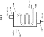
- FIG. 3 shows a heat exchanger 302 for heating of the liquid fuel prior to entry into the evaporation zone, in accordance with one or more embodiments.
- the heat exchanger 302 can be located upstream of the evaporation zone(s). As shown in FIG.
- the heat exchanger 302 can have a first inlet 304 for the fuel, a second inlet 306 for the oxygen-depleted air stream, a first outlet 308 for the fuel, and a second outlet 310 for the oxygen-depleted air stream.
- the second inlet 306 can be connected to the air stream conduit 155 (or 255) for receiving the oxygen-depleted air
- the first outlet 308 can connect to the inlet 120 (220) of the atomizer 115 (or 215).
- the heat from the oxygen-depleted air stream can be transferred to the fuel stream in the heat exchanger 302 in any number of ways known to those of ordinary skill in the art. Further, the exiting oxygen depleted air is generally N 2 rich and can be used in industrial processes such as fertilizer industries.
- the systems of the present application can be self-heating in that they can use the combustion reaction in the reaction zone to heat the ITMs to a desired temperature. Further, the energy provided by the partial recirculation of the exhaust gas stream exiting the reaction zone helps to maintain the ITM temperature.
- the present systems are closed-loop control systems wherein the ITM temperature is maintained at a constant level in order to avoid thermal stresses in the ITM and improve thermal performance.
- each ITM can be one continuous membrane surrounding the reaction zone.
- the ITMs can be a series of ITM tubes. More specifically, in certain embodiments, the ITM tubes can be situated within the reaction zone and perpendicular to the sweep flow (atomized fuel and CO 2 entering the reaction zone) to enhance the oxygen permeation across the ITMs. In other words, in embodiments in which the sweep flow is perpendicular to the ITMs, the ITMs are considered "cross-flow" ITMs, as compared with "coaxial-flow” ITMs in which the sweep flow is parallel to the ITMs.
- FIGS. 4A-B show schematic drawings of the operation of a cross-flow ITM ( FIG. 4A ) compared with the operation of a co-axial flow ITM ( FIG. 4B ).
- FIG. 5 shows a side view of an alternative embodiment of the gas-assisted liquid fuel oxygen reactor having cross-flow ion transport membranes.
- the system 500 can operate in similar fashion as systems 100 and 200, and can comprise all or substantially all of the same elements as shown in the embodiments of FIGS. 1 and 2 , including but not limited to an evaporation zone 505, a fuel filter 540, a reaction zone 545, ITMs 550 (in this embodiment, ITM tubes 550), conductive plates/walls (not shown), and an air plus gaseous fuel stream conduit 560.
- the air stream in system 500 is fed directly into the ITM tubes 550 (as opposed to flowing along an exterior thereof), and oxygen (O 2 ) from the air stream then permeates from inside the ITM tubes 550 to the reaction zone 545 on the outside of the ITM tubes 550 as shown in FIG. 5 .
- the ITM tubes 550 are situated within the reaction zone 545, and the inside of the ITM tubes 550 function as air conduits.
- the reaction zone was located internally within the ITM tube, while in this embodiment, the reaction zone is located external to the ITM tube(s).
- the vaporized fuel and CO 2 stream flows through the fuel filter 540 into the reaction zone 545.
- the flow of the vaporized fuel and CO 2 is a "cross-flow" stream that is perpendicular to the ITM tubes 550.
- the ITM tubes 550 can be vertically oriented from top to bottom in the reaction zone. The cross-flow of the vaporized fuel and CO 2 enhances the oxygen permeation from the air stream through the ITM tubes 550, thereby enhancing the efficiency of the combustion reaction in the reaction zone 545.
- the exhaust gas streams, oxygen-depleted air streams, and the air plus gaseous fuel streams can be recirculated in the system for heating purposes in a similar fashion as described for the embodiments of FIGS. 1 and 2 , including the use of one or more heat exchangers (see FIG. 3 ).
Description
- The present disclosure relates to methods and systems for combustion and carbon capture, more particularly, methods and systems involving oxygen transport reactors for the combustion of liquid fuels and the efficient capture of carbon dioxide.
- Fossil fuels remain the main source of energy, particularly in the transportation industry. However, due to the large CO2 production associated with fossil fuel use, it is also a major contributor to global warming.
- Among these fossil fuels, liquid fuels are being widely used in the transportation industry because of their safety and high calorific values. Liquid fuels still produce large amounts of CO2, and in order to capture the CO2, different techniques are currently available including pre-combustion, post-combustion, and oxyfuel combustion technologies. Currently, oxyfuel combustion technologies are considered some of the most promising carbon capture technologies. For oxyfuel combustion, oxygen is burnt in a combustion chamber with fuel and the combustion products include only CO2 and H2O. The CO2 and H2O can then be separated via a condensation process leaving behind only CO2 that can be recycled or stored through the sequestration process. This process requires pure oxygen (O2), obtained via cryogenic distillation for example. However the cryogenic distillation process of separation of O2 from the air is very costly.
- One of the alternatives for the separation of O2 from air that may be more cost effective is the use of Ion Transport Membranes (ITMs), which can reduce the penalty of air separation units in oxy-combustion. These ITMs have the capability of separating the O2 from air at elevated temperatures, typically above 700°C. Oxygen permeation through these membranes is a function of partial pressure of oxygen across the membranes, membrane thickness, and the temperature at which these membranes are operating. When the combustion is done simultaneously with the O2 separation via ITMs, the unit is generally referred to as an oxygen transport reactor.
- One of the main challenges of oxygen transport reactors is the low fluxes that are obtained by the membranes. Under these low fluxes the heat rates generated in a given volume is relatively low.
- As such, there is a need for an oxygen transport reactor that addresses the deficiencies of the prior art, namely the low fluxes obtained by the membranes and consequently the issue of heating up the membranes economically.
-
US2015176487 discloses an oxygen transport reactor for boiler furnaces and gas turbine combustors that utilizes a liquid fuel that is oxidized as a gaseous fuel in a membrane reactor. A liquid fuel is introduced by vaporizing the fuel inside a porous pipe surrounded by an annulus reaction zone which is surrounded by an annulus air zone. An oxygen transport membrane separates the annulus reaction zone containing the porous vaporized fuel and sweeping CO2 from the air feed side zone. Oxygen is transported from the outer annulus through the membrane to the annulus reaction zone containing the vaporized fuel and sweeping CO2. Fuel is first cracked to very small droplets in the intake fuel atomizer utilizing part of the intake CO2 then completely vaporized inside the porous pipe utilizing the heat coming from the surrounding reaction zone. The oxygen transport reactor is applicable for carbon free boiler furnaces and gas turbine combustors which utilize oxygen transport reactors for combined oxygen separation and combustion. - According to a first and second aspects, a gas-assisted liquid fuel oxygen reactor system according to
claims 1 and 7 is provided. According to another aspect, a method for low-C02 emission combustion of a liquid fuel in a gas-assisted liquid fuel oxygen reactor according to claim 13 is provided. Further developments of the invention can be taken from the dependent claims. - Further aspects of the present application will be more readily appreciated upon review of the detailed description of its various embodiments, described below, when taken in conjunction with the accompanying drawings, of which:
-
FIG. 1 is a cross-sectional view of the gas-assisted liquid fuel oxygen reactor in a cylindrical configuration in accordance with one or more embodiments; -
FIG. 2 is a cross-sectional view of an embodiment of the gas-assisted liquid fuel oxygen reactor in a periodic planar configuration having multiple reaction zones in accordance with one or more embodiments; -
FIG. 3 is a schematic of a heat exchanger associated with the gas-assisted liquid fuel oxygen reactor in accordance with one or more embodiments; -
FIGS. 4A-B are schematic drawings comparing the operation of a cross-flow ion transport membrane (4A) with the operation of a co-axial flow ion transport membrane (4B) in accordance with one or more embodiments; -
FIG. 5 is a side view of an embodiment of the gas-assisted liquid fuel oxygen reactor having cross-flow ion transport membranes in accordance with one or more embodiments; -
FIG. 6 is a line graph showing the oxygen permeation rate through the ion transport membrane for non-reactive and reactive cases with increasing percentage of CH4 in the sweep gas, in accordance with one or more embodiments; and -
FIG. 7 is a graph showing the reaction rates in the reaction zone with an increasing percentage of CH4 in the sweep gas, in accordance with one or more embodiments. - The present disclosure details systems and methods for a gas-assisted liquid fuel oxygen transport reactor. In particular, the present application discloses a low-carbon emission oxygen transport reactor for liquid fuel which utilizes gas combustion. In one or more embodiments, the present system comprises a gas-assisted (e.g., CO2 gas) atomizer that provides an atomized spray of liquid fuel and gas into an evaporation zone. The atomized fuel and gas is heated in the evaporation zone and then permeates through a fuel filter into a reaction zone (oxygen transport reactor). A flow of air (air stream) is also fed into the system in a conduit (vessel) adjacent to the reaction zone. This air stream conduit and the reaction zone are separated by one or more ion transport membranes. Due to the conditions of the air stream conduit, the oxygen from the air stream permeates through the ion transport membrane and into the reaction zone. The combination of the atomized fuel and gas and the permeated oxygen in the reaction zone results in the combustion of the fuel and the production of heat.
- In conventional methods, the ion transport membrane operates under low flux, and as such, the rate of heat generated by the reaction zone is relatively low. The system of the present application, however, utilizes the stream of atomized gas (e.g., CO2) as a sweep gas to increase the fluxes of oxygen obtained in the reaction zone through the ion transport membrane. Further, the present system is a closed-loop control system in which the gas and air streams are recirculated throughout the system to maintain a constant temperature at the ion transport membrane. For instance, the gas combustion reactions in the reaction zone are used to heat the ion transport membrane(s) to the desired temperature, and the energy required for maintaining the temperature at the ion transport membrane is provided by the partial recirculation of the exhaust gases exiting the reaction zone. Similarly, after losing oxygen via the ion transport membrane, the now oxygen-depleted air stream (flow) can also be used to recirculate heat within the system by providing heat to the liquid fuel via a heat exchanger prior to its entry into the evaporation zone. Maintaining a constant temperature at the ion transport membrane avoids thermal stresses in the ion transport membrane, and thus results in improved membrane stability and thermal performance.
- The systems and methods of the present application allow for efficient self-heating of the system, as well as storage of CO2 from the exhaust gases, which significantly reduces CO2 emissions. Further, because the combustion of the fuel is conducted with oxygen rather than air, the system does not result in the emission of NOx.
- The referenced systems and methods for a gas-assisted liquid fuel oxygen transport reactor are now described more fully with reference to the accompanying drawings, in which one or more illustrated embodiments and/or arrangements of the systems and methods are shown. The systems and methods are not limited in any way to the illustrated embodiments and/or arrangements as the illustrated embodiments and/or arrangements are merely exemplary of the systems and methods, which can be embodied in various forms as appreciated by one skilled in the art. Therefore, it is to be understood that any structural and functional details disclosed herein are not to be interpreted as limiting the systems and methods, but rather are provided as a representative embodiment and/or arrangement for teaching one skilled in the art one or more ways to implement the systems and methods.
-
FIG. 1 illustrates a cross-sectional view of anexemplary system 100 for a gas-assisted liquid fuel oxygen transport reactor. In this embodiment, thesystem 100 has a cylindrical configuration, such as a cylindrical pipe. In at least one embodiment, the system can have a planar configuration having horizontal fuel injection slots. As described herein, when thesystem 100 has a cylindrical shape, the system is made up of a series of concentric zones/regions. Thesystem 100 can generally be thought to include afirst end 102 and an opposingsecond end 104. - The
cylindrical system 100 includes anevaporation zone 105. The evaporation zone includes aninlet 110 for receiving afuel atomizer 115. Liquid fuel is injected into theevaporation zone 105 via thefuel atomizer 115. The liquid fuel can comprise one or more compounds including but not limited to methane (CH4), but can also include gaseous fuels and light liquid fuels. In one or more embodiments, thefuel atomizer 115 is gas-assisted (e.g., CO2-assisted). In an alternative embodiment, thefuel atomizer 115 can be a liquid fuel pressure atomizer. Thefuel atomizer 115 can include aninlet 120 for receiving the liquid fuel and anoutlet 125 adapted to spray liquid droplets of the atomized fuel and gas (e.g., CO2) into theevaporation zone 105. Thefuel atomizer 115 thus defines one end of theevaporation zone 105. Theevaporation zone 105 further includes anouter wall 130 which can have an annular shape as shown. In one or more embodiments, theouter wall 130 can comprise one or more (thermal) conductive plates, which can be used to heat the atomized (i.e., liquid droplet) fuel and gas into a vaporized form as will be explained in greater detail below. In at least one embodiment, theevaporation zone 105 can further comprise abluff body 135. Thebluff body 135 can be used in the evaporation zone to assist in completion of the fuel evaporation and to stabilize the flame. The flame is located in thereaction zone 145. Thebluff body 135 is located downstream of theatomizer 115. - With continued reference to
FIG. 1 , after evaporation of the fuel and gas (e.g., CO2), the vaporized fuel and gas flow across afuel filter 140 and into a reaction zone (oxygen transport reactor) 145. In particular, the flow of the CO2 from the atomizer acts as a sweep gas pushing the atomized fuel through thefuel filter 140 and into thereaction zone 145. Thefuel filter 140 ensures the removal of unwanted contaminants from the vaporized fuel and gas prior to entry into thereaction zone 145. Thefuel filter 140 extends across (transverses) theevaporation zone 105 and is thus positioned such that the vaporized fuel and gas from the atomizer flows directly into and through thefuel filter 140. In one or more embodiments and as shown inFIG. 1 , thereaction zone 145 is coaxially aligned with theevaporation zone 105 and located downstream thereof. Further, in the embodiment shown inFIG. 1 , theevaporation zone 105 andreaction zone 145 are located in the innermost area (the core) of the cylindrical configuration (e.g., pipe). - As shown in
FIG. 1 , in one or more embodiments, thereaction zone 145 is surrounded by one or more ion transport membranes (ITMs) 150. In one or more implementations, theITMs 150 are made of ceramic materials. In the illustrated embodiment, theITM 150 has an annular shape with thereaction zone 145 being internal thereto. In at least one embodiment, such as when the system has a planar configuration, theITM 150 can comprise a first and a second planar membrane surface, where thereaction zone 145 is disposed between the two planar membrane surfaces. - Exemplary ITM materials and additional properties of the ITM are disclosed in published paper by Behrouzifar et al. (Experimental Investigation and Mathematical Modeling of Oxygen Permeation Through Dense Ba0.5Sr0.5Co0.8Fe0.2O3-δ (BSCF) Perovskite-type Ceramic Membranes. Ceramics International: 38 (2012); 4797-4811). As discussed in the published paper by Behrouzifar et al., it should be appreciated that membrane thickness and temperature can affect oxygen flux across the ITMs. In particular, oxygen flux across the ITM generally increases with increased temperatures around the membrane, as well as with thinner membranes.
- Surrounding the one or more ITMs is a first conduit 155 (air vessel). The
first conduit 155 comprises an inlet (not shown) for an air stream. As with other components and features of thesystem 100, thefirst conduit 155 can have an annular shape and be concentric with the evaporation and reaction zones. As described below, thefirst conduit 155 is defined by ITMs 150 (and in part outer wall 130) and by an outer wall structure described below. The mixture of evaporated fuel and sweep gas in thereaction zone 145 induces oxygen from the air stream flowing in thefirst conduit 155 to transfer across theITMs 150 into thereaction zone 145. In particular, the sweep gas (e.g., CO2) in the reaction zone increases the fluxes of oxygen obtained through (across) theITMs 150, thus inducing oxygen transport from the air stream (in conduit 145) across theITMs 150. - Further, the air stream is fed into the
system 100 in a counter-flow process in that the air stream flows in the opposite direction of the sweep gas/vaporized fuel. This counter flow process provides at least some of the energy required to heat the air stream and thus to maintain uniform temperature along the ITMs, which allows for improved membrane stability. The transport of oxygen into thereaction zone 145 results in the combustion of the fuel in thereaction zone 145, thereby resulting in the production of heat. In one or more embodiments, an increase in the percentage of fuel (e.g., CH4) in the sweep gas results in increased oxygen permeation through theITMs 150 as well as increased reaction rates in the reaction zone 145 (SeeFIGS. 6-7 ). - The combustion reaction also produces exhausts gases comprising CO2 and water vapor. In one or more embodiments, at least part of the exhaust gases can be recirculated to provide partial heating to the air stream via (thermal)
conductive plates 165, providing even greater oxygen flux across theITMs 150. The air stream is heated by radiation from the combustion gases in thereaction zone 145. The heated air (oxygen depleted air) exiting 155 is to be circulated into asecond conduit 160 to keep the high temperature of the air in 155. In at least one embodiment, combustion gases using air and fuel (burned outside of 100) are passed into the second conduit160 as a source of heating to the air in 155. - Further, in one or more embodiments, the water vapor in the exhausted gases can be condensed leaving essentially only CO2 in the exhaust gas stream, which can then be stored to reduce CO2 emissions. Specifically, the
gases leaving zone 155 can pass into a condenser (not shown) to condense the water vapor leaving CO2 that can be compressed and stored. - As mentioned above, the air stream of
conduit 155 is heated, which helps to maintain uniform temperature along theITMs 150 allowing for improved membrane stability. In one or more embodiments, during operation, the ITMs are maintained at a temperature in the range of approximately 700°C to approximately 900°C. The determination of the preferred temperature depends on an optimization of the high oxygen flux that can be achieved at high temperatures and the constraint of the thermal and mechanical stability of the ITM materials. - Unlike many conventional systems, the systems of the present application provide for combustion of fuel using oxygen rather than air, thus resulting in an exhaust stream that is free of nitrogen oxides (NOx). Thus the systems of the present application are zero-NOx emission systems.
- With continued reference to
FIG. 1 , after permeation of oxygen from the air stream through theITMs 150, the now oxygen-depleted air stream infirst conduit 155 can also be recirculated. In particular, the energy available in the oxygen-depleted air can be utilized to heat the fuel prior to entry into theevaporation chamber 105 via a heat exchanger, for example (seeFIG. 3 ). As shown inFIG. 1 , in at least one embodiment, the oxygen-depleted air ofconduit 155 can also heat the fuel in theevaporation zone 105 via conductive plates in theouter wall 130. - As mentioned above, in at least one embodiment, the
system 100 can also comprise a second conduit 160 (heating vessel) surrounding thefirst conduit 155, thesecond conduit 160 andfirst conduit 155 being separated by at least one (thermal) conductive wall/plate 165. The (thermal) conductive wall/plate 165 thus defines both thefirst conduit 155 and thesecond conduit 160. The (thermal) conductive wall/plate 165 can have an annular shape. - The
second conduit 160 can comprises an inlet (not shown) for a stream of hot air/gaseous fuel stream. The hot air/gaseous fuel stream can provide heat to the air stream of thefirst conduit 155 via the (thermal) conductive walls/plates 165, thereby resulting in better oxygen flux from the air stream across theITMs 150. In one or more embodiments, thecylindrical system 100 further comprises anouter wall 170 which serves as the outer barrier of thesecond conduit 160 and thus defines thesecond conduit 160. - It will also be understood that a fluid seal is formed between the
outer wall 130 and theITMs 150. As shown inFig. 1 , one end of theouter wall 130 abuts and seals against one end of theITMs 150. - It will therefore be appreciated that, as shown in
Fig. 1 , thesystem 100 can include a series of flow paths that allow for a series of counter fluid flow. More specifically, in the illustrated embodiment, fluid flow in the evaporation and reaction zones and thesecond conduit 160 is in the same direction (parallel flow paths) and the fluid flow in thefirst conduit 155 is in the opposite direction (counter flow path). In addition, the various zones and flow paths are arranged in a concentric manner due to the fact that in the illustrated embodiment, thesystem 100 has a cylindrical shape defined at least in part by a series of concentric annular shaped zones/flow paths. - It will also be appreciated that the sizes of the different zones/flow paths can be varied and the present figures are merely exemplary and not limiting of the present invention. In addition, the direction of flow of each flow path is merely exemplary and not limiting in
Fig. 1 in that flow shown as being from left to right can equally be from the right to the left. - It should also be understood that while
Fig. 1 (system 100) is described as a cylindrical configuration, in at least one embodiment, the system can have a planar configuration such that theITM 150 can comprise a first and a second planar membrane surface, where thereaction zone 145 is disposed between the two planar membrane surfaces. In this embodiment, the first conduit 155 (air vessel) can comprise first and second planar plates (conductive plates 165) with the first and second planar membrane surfaces disposed there between. Further, the second conduit 160 (heating vessel) can be defined by a planarouter wall 170 and the planarconductive plates 165. -
FIG. 2 shows a cross-sectional view of a second embodiment of the gas-assisted liquid fueloxygen reactor system 200 in a periodic planar configuration having multiple reaction zones in accordance with one or more embodiments. Also, in at least one embodiment, it is possible to use multiple, separated cylindrical systems such as the cylindrical system ofFig. 1 . - As shown in
FIG. 2 , thesystem 200 functions in a similar fashion as the embodiment ofFIG. 1 . In contrast tosystem 100 which represents a single stage type system, thesystem 200 represents a two stage type system in that there are two sets of the components and flow paths described with reference toFig. 1 and as described below. - Thus, in this embodiment, the
system 200 comprises twoevaporation zones 205 each having aninlet 210 for receiving anatomizer 215, such as a gas- (e.g., CO2) assisted atomizer. The liquid fuel (and CO2) are injected into the atomizers 215 (via inlets 220) and sprayed (via outlets 225) into theevaporation zones 205. In theevaporation zones 205, the fuel and CO2 are vaporized using heat from (thermal)conductive plates 230. In certain embodiments, eachevaporation zone 205 further comprises abluff body 235. - With continued reference to
FIG. 2 , the vaporized fuel and CO2 permeate throughfuel filters 240 and flow into thereaction zones 245, thereaction zones 245 each being coaxially aligned with therespective evaporation zone 205. In the periodic planar configuration ofFIG. 2 , thereaction zones 245 are each disposed betweenITMs 250. More specifically, in this embodiment, theITMs 250 can comprise planar membranes, where eachreaction zone 245 is disposed between a first and second planar membrane. Bordering theITMs 250 are air stream conduits 255 (air vessels) having inlets (not shown) for heated air streams. Oxygen from the heated air streams permeate through theITMs 250 and into thereaction zones 245, resulting in a combustion reaction with the vaporized fuel and CO2 stream. The combustion reaction produces heat, as well as exhausts gases comprising CO2 and water vapor. At least part of the exhaust gases can be recirculated to provide partial heating to the air stream via conductive plates for better oxygen flux across theITMs 250. Again, in this embodiment, the water vapor in the exhausted gases can be condensed leaving essentially only CO2 in the exhaust gas stream, which can then be stored in order to reduce CO2 emissions. As discussed below, eachconduit 255 can comprise at least one planarconductive plate 265, which provides heat from the hot air/gaseous fuel stream inconduit 260 to the air stream inconduit 255. As in the first embodiment, theITMs 250 are maintained at a temperature in the range of approximately 700°C to approximately 900°C. - After permeation of oxygen from the air streams in the
air stream conduits 255, the now oxygen-depleted air streams can also be recirculated to heat the fuel prior to entry into theevaporation zones 205 via one or more heat exchangers, for example. Thesystem 200 can also comprise air andgaseous fuel conduits 260, which borders theair stream conduits 255, theconduits 260 being separated fromconduits 255 by (thermal) conductive walls/plates 265. Theconduits 260 can each comprise an inlet (not shown) for a stream of hot air/gaseous fuel. The hot air/gaseous fuel stream can provide heat to the air stream ofconduits 255 via the (thermal) conductive walls/plates 265, thereby resulting in better oxygen flux from the air stream across theITMs 250. Thesystem 200 can further comprises anouter wall 270 which serves as the outer barrier of theconduits 260 comprising the air/gaseous fuel streams. Certain periodic planar embodiments, such as that ofFIG. 2 , can provide enhanced efficiency since they avoid energy losses that can sometimes occur throughouter wall 170 in a cylindrical configuration. - It should be understood from
FIG. 2 that, in certain embodiments, the system can comprise several reaction zones (i.e., two or more) each coaxially aligned with its own evaporation zone, and each being disposed between planar ITMs, an air stream conduit, and/or an air plus gaseous fuel conduit. Each evaporation zone, ITM (first and second planar membranes), air stream conduit, and air/gaseous fuel conduit (with a reaction zone disposed between the planar membranes) can be thought of as collectively making up a reactor unit, and in certain embodiments, two or more reactor units can be combined, in a stacked orientation for example. For instance,FIG. 2 displays two reactor units in a stacked orientation. In one or more embodiments, for each reaction unit, the reaction zone is disposed between first and second planar membranes, and the first and second planar membranes are disposed between first and second planar plates of the air vessel (conduit 255). - It should also be appreciated that, in one or more embodiments, a manifold-type structure can be used to create multiple flow paths from a single source. For instance, in a periodic planar configuration as shown
FIG. 2 , there can be a single source of the liquid fuel, and a manifold structure can be used to split the liquid stream into multiple flow paths for entry into themultiple evaporation zones 205. In certain embodiments, there can also be similar manifold-like structures for other like fluid streams in the system, such as the air streams ofconduits 255. Alternatively, in at least one embodiment, there can be a separate source for each liquid fuel stream for entry into eachevaporation zone 205, as well as separate sources for other like fluid streams in thesystem 200. - As mentioned in the above embodiments, the energy available in the oxygen-depleted air stream in conduit 155 (or conduit 255) following permeation of oxygen through the ITMs can be utilized to heat the liquid fuel prior to entry into the evaporation chamber via one or more heat exchangers.
FIG. 3 shows aheat exchanger 302 for heating of the liquid fuel prior to entry into the evaporation zone, in accordance with one or more embodiments. Theheat exchanger 302 can be located upstream of the evaporation zone(s). As shown inFIG. 3 , theheat exchanger 302 can have afirst inlet 304 for the fuel, asecond inlet 306 for the oxygen-depleted air stream, afirst outlet 308 for the fuel, and asecond outlet 310 for the oxygen-depleted air stream. Thesecond inlet 306 can be connected to the air stream conduit 155 (or 255) for receiving the oxygen-depleted air, and thefirst outlet 308 can connect to the inlet 120 (220) of the atomizer 115 (or 215). The heat from the oxygen-depleted air stream can be transferred to the fuel stream in theheat exchanger 302 in any number of ways known to those of ordinary skill in the art. Further, the exiting oxygen depleted air is generally N2 rich and can be used in industrial processes such as fertilizer industries. - As mentioned above, in accordance with one or more embodiments, the systems of the present application can be self-heating in that they can use the combustion reaction in the reaction zone to heat the ITMs to a desired temperature. Further, the energy provided by the partial recirculation of the exhaust gas stream exiting the reaction zone helps to maintain the ITM temperature. Thus, in these embodiments, the present systems are closed-loop control systems wherein the ITM temperature is maintained at a constant level in order to avoid thermal stresses in the ITM and improve thermal performance.
- In one or more embodiments, each ITM can be one continuous membrane surrounding the reaction zone. In at least one implementation, the ITMs can be a series of ITM tubes. More specifically, in certain embodiments, the ITM tubes can be situated within the reaction zone and perpendicular to the sweep flow (atomized fuel and CO2 entering the reaction zone) to enhance the oxygen permeation across the ITMs. In other words, in embodiments in which the sweep flow is perpendicular to the ITMs, the ITMs are considered "cross-flow" ITMs, as compared with "coaxial-flow" ITMs in which the sweep flow is parallel to the ITMs.
FIGS. 4A-B show schematic drawings of the operation of a cross-flow ITM (FIG. 4A ) compared with the operation of a co-axial flow ITM (FIG. 4B ). -
FIG. 5 shows a side view of an alternative embodiment of the gas-assisted liquid fuel oxygen reactor having cross-flow ion transport membranes. In this embodiment, thesystem 500 can operate in similar fashion assystems FIGS. 1 and2 , including but not limited to anevaporation zone 505, afuel filter 540, areaction zone 545, ITMs 550 (in this embodiment, ITM tubes 550), conductive plates/walls (not shown), and an air plus gaseousfuel stream conduit 560. - However, unlike the embodiments above, the air stream in
system 500 is fed directly into the ITM tubes 550 (as opposed to flowing along an exterior thereof), and oxygen (O2) from the air stream then permeates from inside theITM tubes 550 to thereaction zone 545 on the outside of theITM tubes 550 as shown inFIG. 5 . In other words, in this embodiment, theITM tubes 550 are situated within thereaction zone 545, and the inside of theITM tubes 550 function as air conduits. In the previous embodiment, the reaction zone was located internally within the ITM tube, while in this embodiment, the reaction zone is located external to the ITM tube(s). - In this embodiment, after heating of the liquid fuel and CO2 in the
evaporation zone 505, the vaporized fuel and CO2 stream flows through thefuel filter 540 into thereaction zone 545. Here, the flow of the vaporized fuel and CO2 is a "cross-flow" stream that is perpendicular to theITM tubes 550. For example, theITM tubes 550 can be vertically oriented from top to bottom in the reaction zone. The cross-flow of the vaporized fuel and CO2 enhances the oxygen permeation from the air stream through theITM tubes 550, thereby enhancing the efficiency of the combustion reaction in thereaction zone 545. In one or more implementations of the embodiment ofFIG. 5 (i.e., cross-flow ITMs), the exhaust gas streams, oxygen-depleted air streams, and the air plus gaseous fuel streams can be recirculated in the system for heating purposes in a similar fashion as described for the embodiments ofFIGS. 1 and2 , including the use of one or more heat exchangers (seeFIG. 3 ). - While the present invention has been described above using specific embodiments, there are many variations and modifications that will be apparent to those having ordinary skill in the art. As such, the described embodiments are to be considered in all respects as illustrative, and not restrictive. The scope of the invention is, therefore, indicated by the appended claims, rather than by the foregoing description. All changes that come within the meaning and range of equivalency of the claims are to be embraced within their scope.
Claims (18)
- A gas-assisted liquid fuel oxygen reactor system, comprising:a CO2-assisted atomizer (115, 215) having an inlet (120, 220) adapted to receive a liquid fuel and an outlet (125, 225) adapted to spray atomized fuel and CO2;an evaporation zone (105, 205) having an inlet adapted to receive the atomized liquid fuel and CO2 and having an outer wall (130, 230) that is formed of a thermally conductive material such that the evaporation zone (105, 205) is adapted to heat the atomized fuel and CO2 into a vaporized form;a reaction zone (145, 245) co-axially aligned with and in flow communication with the evaporation zone (105, 205), wherein the reaction zone (145, 245) is adapted to receive a flow of the vaporized fuel and CO2 from the evaporation zone (105, 205);an ion transport membrane (150, 250) that is coaxially aligned with the evaporation zone (105, 205) and defines the reaction zone (145, 245);an air vessel (155, 255) defined by structure that is disposed about the ion transport membrane (150, 250) and defines a first space between an outer surface of the ion transport membrane and an inner surface of the air vessel structure, wherein the air vessel structure is formed of a thermally conductive material and the air vessel (155, 255) is for receiving an air stream that flows in a counter direction relative to a flow of the vaporized fuel and CO2 in the reaction zone (145, 245); wherein the ion transport membrane (150, 250) is adapted to provide O2 permeating from the air stream and transfer the O2 into the reaction zone (145, 245) resulting in an O2-depleted air stream in the first space of the air vessel structure, and wherein the reaction zone (145, 245) is adapted to combust the vaporized fuel and CO2 in the presence of O2 to produce heat and create exhaust gases that are recirculated in the system;characterized in that it comprises:
a heating vessel (160, 260) defined by a structure that is disposed about the air vessel structure and defines a second space between an outer surface of the air vessel structure and an inner surface of the heating vessel structure, wherein the heating vessel (160, 260) is for receiving a heated air and gaseous fuel stream such that heat is transferred from the air and gaseous fuel stream to the first space. - The system of claim 1, characterized in that it comprises:a fuel filter (140, 240) situated between the evaporation zone (105, 205) and the reaction zone (145, 245) and adapted to remove unwanted contaminants from the vaporized fuel and CO2 prior to entry of the vaporized fuel and CO2 into the reaction zone (145, 245); anda bluff body (135, 235) located within the evaporation zone (105, 205) and adapted to assist in the evaporation of the fuel.
- The system of claim 1, characterized in that the recirculation of the exhaust gases provides energy to the system to maintain an at least substantially constant temperature at the ion transport membrane (150, 250), and wherein a temperature at the ion transport membrane (150, 250) is maintained between 700°C and 900°C.
- The system of claim 1, characterized in that it comprises:
a heat exchanger (302) located upstream of the CO2-assisted atomizer (115, 215), the heat exchanger (302) being adapted to receive the O2-depleted air stream from the air vessel (155, 255) and the liquid fuel, and adapted to transfer heat from the O2-depleted air stream to the liquid fuel prior to reception of the liquid fuel in the CO2-assisted atomizer (115, 215). - The system of claim 1, wherein the system has a cylindrical shape with the ion transport membrane (150, 250), the air vessel structure and the heating vessel structure being concentric to one another, and wherein the reaction zone (145, 245) is located internally to the ion transport membrane (150, 250).
- The system of claim 1, characterized in that the ion transport membrane (150, 250) comprises first and second planar membranes with the reaction zone (145, 245) disposed there between, the air vessel (155, 255) comprises first and second planar plates (165, 265) with the ion transport membrane (150, 250) disposed there between, and wherein the evaporation zone (105, 205), the ion transport membrane (150, 250), the air vessel (155, 255), and the heating vessel (160, 260) define a first reactor unit, and wherein the system further includes at least a second reactor unit, the second reactor unit having an identical construction as the first reactor unit, the first and second reactor units being in a stacked orientation.
- A gas-assisted liquid fuel oxygen reactor system, comprising:a CO2-assisted atomizer (115, 215) having an inlet (120, 220) adapted to receive a liquid fuel and an outlet (125, 225) adapted to spray atomized fuel and CO2;an evaporation zone (505) having an inlet adapted to receive the atomized liquid fuel and CO2;a reaction zone (545) co-axially aligned and in flow communication with the evaporation zone (505) such that the reaction zone (545) receives a flow of the vaporized fuel and CO2 from the evaporation zone (505); characterized in that it comprises:a series of tubes (550) comprised of ion transport membranes situated within the reaction zone and oriented perpendicularly to the flow of the vaporized fuel and CO2 in the reaction zone (545), wherein the tubes (550) are adapted to internally receive an air stream and allow permeation of O2 from the air stream through the ion transport membranes to the reaction zone (545) which surrounds the ion transport membranes, thereby resulting in an O2-depleted air stream inside the ion transport membranes and a combustion reaction in the reaction zone (545) which is located external to the ion transport membranes, wherein the combustion reaction produces heat and creates exhaust gases that are recirculated in the system; anda heating vessel (560) comprising an inlet for a heated air and gaseous fuel stream, wherein the heating vessel (560) defined by a structure that surrounds the reaction zone (545) such that heat is transferred from the heated air and gaseous fuel stream to the reaction zone (545).
- The system of claim 7, characterized in that it comprises:
a fuel filter (540) situated between the evaporation zone (505) and the reaction zone (545) and adapted to remove unwanted contaminants from the vaporized fuel and CO2 prior to entry of the vaporized fuel and CO2 into the reaction zone (545). - The system of claim 7, characterized in that the recirculation of the exhaust gases provides energy to the system to maintain a constant temperature at the ion transport membrane, and wherein the constant temperature of the ion transport membrane is between 700°C and 900°C.
- The system of claim 7, characterized in that it comprises:
a heat exchanger located upstream of the CO2-assisted atomizer (115, 215), the heat exchanger being adapted to receive the O2-depleted air stream from the tubes (550) and the liquid fuel, and adapted to transfer heat from the O2-depleted air stream to the liquid fuel prior to reception of the liquid fuel in the CO2-assisted atomizer (115, 215). - The system of claim 7, characterized in that the system has a cylindrical configuration with the ion transport membranes extending transversely across the system.
- The system of claim 7, characterized in that the atomized liquid fuel and CO2 and the heated air and gaseous fuel stream both flow in the same direction which is at least generally perpendicular to the flow of the air stream.
- A method for low-CO2 emission combustion of a liquid fuel in a gas-assisted liquid fuel oxygen reactor, the method comprising:injecting a liquid fuel into an evaporation zone (105, 205), wherein the fuel is injected via a CO2-assisted atomizer (115, 215) adapted to spray the liquid fuel and CO2 into the evaporation zone (105, 205);vaporizing the liquid fuel and CO2 in the evaporation zone (105, 205), resulting in a mixture of evaporated fuel and CO2;flowing the mixture of evaporated fuel and CO2 into a reaction zone (145, 245) which is coaxial to the evaporation zone (105, 205);supplying a flow of air into an air vessel (155, 255), wherein the air vessel (155, 255) and reaction zone (145, 245) are separated by an ion transport membrane (150, 250), and wherein O2 permeates from the flow of air through the ion transport membrane (150, 250) and into the reaction zone (145, 245) resulting in an O2-depleted air stream in the air vessel (155, 255);combusting the evaporated fuel and CO2 in the presence of O2 in the reaction zone (145, 245) to produce heat and create an exhaust gas stream and characterized in that it comprises the step of:
delivering a hot air and gaseous fuel stream into a heating vessel (160, 260) adjacent to the air vessel (155, 255), wherein heat from the hot air and gaseous fuel stream is transferred to the air vessel (155, 255) via conductive plates (165, 265) separating the heating vessel (160, 260) and the air vessel (155, 255). - The method of claim 13, characterized in that it comprises:
heating the liquid fuel prior to injection of the liquid fuel into the evaporation zone (105, 205), wherein the liquid fuel is heated via a heat exchanger (302), and wherein the step of heating the liquid fuel comprises recirculating the O2-depleted air stream to the heat exchanger (302) upstream of the reaction zone (145, 245), wherein the recirculated O2-depleted air stream transfers heat to the liquid fuel prior to injection of the liquid fuel into the CO2-assisted atomizer (115, 215). - The method of claim 13, characterized in that the step of vaporizing the liquid fuel comprises:
transferring heat from the hot air and gaseous fuel stream to the evaporation zone (105, 205) via conductive plates lining an outer wall (130, 230) of the evaporation zone (105,205). - The method of claim 13, characterized in that it comprises:
recirculating the exhaust gas stream to transfer heat to the air vessel (155, 255), wherein the heat is transferred to the air vessel (155, 255) via one or more conductive plates (165, 265) lining the air vessel (155, 255). - The method of claim 13, characterized in that it comprises:
filtering the mixture of evaporated fuel and CO2 prior to flowing the mixture into the reaction zone (145, 245), wherein the evaporated fuel and CO2 are filtered via a fuel filter (140, 240). - The method of claim 13, characterized in that the air vessel and the ion transport membrane are located within the reaction zone (145) and wherein the flow of the mixture of evaporated fuel and CO2 into the reaction zone (145) is perpendicular to the ion transport membrane, and in that the ion transport membrane is a tube surrounding the air vessel.
Applications Claiming Priority (2)
| Application Number | Priority Date | Filing Date | Title |
|---|---|---|---|
| US15/087,300 US10215402B2 (en) | 2016-03-31 | 2016-03-31 | Gas-assisted liguid fuel oxygen reactor |
| PCT/US2017/024984 WO2017173062A1 (en) | 2016-03-31 | 2017-03-30 | Gas-assisted liquid fuel oxygen reactor |
Publications (2)
| Publication Number | Publication Date |
|---|---|
| EP3436745A1 EP3436745A1 (en) | 2019-02-06 |
| EP3436745B1 true EP3436745B1 (en) | 2020-02-19 |
Family
ID=58548908
Family Applications (1)
| Application Number | Title | Priority Date | Filing Date |
|---|---|---|---|
| EP17717979.3A Active EP3436745B1 (en) | 2016-03-31 | 2017-03-30 | Gas-assisted liquid fuel oxygen reactor |
Country Status (8)
| Country | Link |
|---|---|
| US (2) | US10215402B2 (en) |
| EP (1) | EP3436745B1 (en) |
| JP (1) | JP6880527B2 (en) |
| KR (1) | KR102292021B1 (en) |
| CN (1) | CN109312919B (en) |
| SA (1) | SA518392203B1 (en) |
| SG (1) | SG11201807189SA (en) |
| WO (1) | WO2017173062A1 (en) |
Families Citing this family (2)
| Publication number | Priority date | Publication date | Assignee | Title |
|---|---|---|---|---|
| CA2490343A1 (en) | 2003-12-17 | 2005-06-17 | Cordis Neurovascular, Inc. | Activatable bioactive implantable medical device and method of use |
| US10845052B1 (en) | 2019-12-20 | 2020-11-24 | Jupiter Oxygen Corporation | Combustion system comprising an annular shroud burner |
Family Cites Families (26)
| Publication number | Priority date | Publication date | Assignee | Title |
|---|---|---|---|---|
| AU706663B2 (en) | 1994-09-23 | 1999-06-17 | Standard Oil Company, The | Oxygen permeable mixed conductor membranes |
| US5562754A (en) | 1995-06-07 | 1996-10-08 | Air Products And Chemicals, Inc. | Production of oxygen by ion transport membranes with steam utilization |
| US5820655A (en) | 1997-04-29 | 1998-10-13 | Praxair Technology, Inc. | Solid Electrolyte ionic conductor reactor design |
| US5954859A (en) * | 1997-11-18 | 1999-09-21 | Praxair Technology, Inc. | Solid electrolyte ionic conductor oxygen production with power generation |
| US6153163A (en) | 1998-06-03 | 2000-11-28 | Praxair Technology, Inc. | Ceramic membrane reformer |
| US6375913B1 (en) | 2000-04-10 | 2002-04-23 | Pranair Technology | Integration of ceramic membrane into a silicon oxide production plant |
| US6293084B1 (en) | 2000-05-04 | 2001-09-25 | Praxair Technology, Inc. | Oxygen separator designed to be integrated with a gas turbine and method of separating oxygen |
| DK1197258T3 (en) | 2000-10-13 | 2011-04-04 | Alstom Technology Ltd | Procedure for operating a power plant |
| US6562104B2 (en) | 2000-12-19 | 2003-05-13 | Praxair Technology, Inc. | Method and system for combusting a fuel |
| US6394043B1 (en) * | 2000-12-19 | 2002-05-28 | Praxair Technology, Inc. | Oxygen separation and combustion apparatus and method |
| DE10064894A1 (en) | 2000-12-23 | 2002-06-27 | Alstom Switzerland Ltd | Air decomposition device, used in power stations, comprises housing separated into chambers by membrane body |
| US6565632B1 (en) | 2001-12-17 | 2003-05-20 | Praxair Technology, Inc. | Ion-transport membrane assembly incorporating internal support |
| US20030223926A1 (en) * | 2002-04-14 | 2003-12-04 | Edlund David J. | Steam reforming fuel processor, burner assembly, and methods of operating the same |
| US7125528B2 (en) | 2002-05-24 | 2006-10-24 | Bp Corporation North America Inc. | Membrane systems containing an oxygen transport membrane and catalyst |
| US7160357B2 (en) | 2003-08-14 | 2007-01-09 | Praxair Technology, Inc. | Oxygen transport membrane reactor and method |
| US7556675B2 (en) | 2005-10-11 | 2009-07-07 | Air Products And Chemicals, Inc. | Feed gas contaminant control in ion transport membrane systems |
| US7384452B2 (en) * | 2005-12-09 | 2008-06-10 | Praxair Technology, Inc. | Fluid heating method |
| KR102046773B1 (en) * | 2009-04-06 | 2019-11-20 | 24엠 테크놀러지스 인코퍼레이티드 | Fuel system using redox flow battery |
| US8820312B2 (en) | 2011-12-06 | 2014-09-02 | King Fahd University Of Petroleum And Minerals | Oxygen transport reactor-based oven |
| US9004909B2 (en) * | 2012-02-03 | 2015-04-14 | Massachusetts Institute Of Technology | Integrated polymeric-ceramic membrane based oxy-fuel combustor |
| US20140174329A1 (en) | 2012-12-26 | 2014-06-26 | King Fahd University Of Petroleum And Minerals | Controlled temperature ion transport membrane reactor |
| US9383096B2 (en) | 2013-12-23 | 2016-07-05 | King Fahd University Of Petroleum And Minerals | Carbon-free low-NOx liquid fuel oxygen transport reactor for industrial water tube boilers |
| US9067172B1 (en) * | 2014-01-28 | 2015-06-30 | Air Products And Chemicals, Inc. | Solid-state membrane module |
| US9702300B2 (en) | 2014-02-12 | 2017-07-11 | King Fahd University Of Petroleum And Minerals | Applications of oxy-fuel combustion technology into gas turbine combustors and ion transport membrane reactors |
| JP2015224148A (en) * | 2014-05-27 | 2015-12-14 | 日本特殊陶業株式会社 | Oxygen-enriched combustion system and method |
| US10202946B2 (en) * | 2016-03-29 | 2019-02-12 | King Fahd University Of Petroleum And Minerals | Power turbine system |
-
2016
- 2016-03-31 US US15/087,300 patent/US10215402B2/en active Active
-
2017
- 2017-03-30 CN CN201780017198.6A patent/CN109312919B/en active Active
- 2017-03-30 EP EP17717979.3A patent/EP3436745B1/en active Active
- 2017-03-30 KR KR1020187031398A patent/KR102292021B1/en active IP Right Grant
- 2017-03-30 SG SG11201807189SA patent/SG11201807189SA/en unknown
- 2017-03-30 WO PCT/US2017/024984 patent/WO2017173062A1/en active Application Filing
- 2017-03-30 JP JP2018546022A patent/JP6880527B2/en active Active
-
2018
- 2018-08-14 SA SA518392203A patent/SA518392203B1/en unknown
-
2019
- 2019-02-04 US US16/267,030 patent/US10995948B2/en active Active
Non-Patent Citations (1)
| Title |
|---|
| None * |
Also Published As
| Publication number | Publication date |
|---|---|
| US10995948B2 (en) | 2021-05-04 |
| WO2017173062A1 (en) | 2017-10-05 |
| CN109312919B (en) | 2020-07-07 |
| JP6880527B2 (en) | 2021-06-02 |
| SG11201807189SA (en) | 2018-10-30 |
| JP2019513963A (en) | 2019-05-30 |
| CN109312919A (en) | 2019-02-05 |
| EP3436745A1 (en) | 2019-02-06 |
| KR102292021B1 (en) | 2021-08-24 |
| US10215402B2 (en) | 2019-02-26 |
| US20190170348A1 (en) | 2019-06-06 |
| SA518392203B1 (en) | 2021-11-30 |
| KR20180136460A (en) | 2018-12-24 |
| US20170284661A1 (en) | 2017-10-05 |
Similar Documents
| Publication | Publication Date | Title |
|---|---|---|
| US6562104B2 (en) | Method and system for combusting a fuel | |
| AU2002230847B2 (en) | Oxygen separation and combustion apparatus and method | |
| US9383096B2 (en) | Carbon-free low-NOx liquid fuel oxygen transport reactor for industrial water tube boilers | |
| US7954458B2 (en) | Boiler having an integrated oxygen producing device | |
| Habib et al. | A review of recent developments in carbon capture utilizing oxy‐fuel combustion in conventional and ion transport membrane systems | |
| CA2809820C (en) | Apparatus for combusting a fuel at high pressure and high temperature, and associated system | |
| US10995948B2 (en) | Gas-assisted liquid fuel oxygen reactor | |
| AU2259200A (en) | Process for enriched combustion using solid electrolyte ionic conductor systems | |
| US20060154189A1 (en) | Method and apparatus for conditioning liquid hydrocarbon fuels | |
| EP1891374B1 (en) | A circulating fluidized bed device provided with an oxygen-fired furnace | |
| US20080131823A1 (en) | Homogeous Combustion Method and Thermal Generator Using Such a Method | |
| CN103968374A (en) | Oxy-Combustion coupled firing and recirculation system | |
| US20230405545A1 (en) | Oxygen transport reactors for co-generating ammonia and power | |
| US10151474B2 (en) | Counterflow ion transport boiler system | |
| Nemitallah | On the effects of fuel type, fuel mixing and sulphur content on the performance of a high-temperature membrane reactor adapting liquid fuel: A numerical study | |
| EP4143483A1 (en) | Burner system and process for natural gas production | |
| CN112292567A (en) | Flameless multi-fuel burner |
Legal Events
| Date | Code | Title | Description |
|---|---|---|---|
| STAA | Information on the status of an ep patent application or granted ep patent |
Free format text: STATUS: UNKNOWN |
|
| STAA | Information on the status of an ep patent application or granted ep patent |
Free format text: STATUS: THE INTERNATIONAL PUBLICATION HAS BEEN MADE |
|
| PUAI | Public reference made under article 153(3) epc to a published international application that has entered the european phase |
Free format text: ORIGINAL CODE: 0009012 |
|
| STAA | Information on the status of an ep patent application or granted ep patent |
Free format text: STATUS: REQUEST FOR EXAMINATION WAS MADE |
|
| 17P | Request for examination filed |
Effective date: 20181023 |
|
| AK | Designated contracting states |
Kind code of ref document: A1 Designated state(s): AL AT BE BG CH CY CZ DE DK EE ES FI FR GB GR HR HU IE IS IT LI LT LU LV MC MK MT NL NO PL PT RO RS SE SI SK SM TR |
|
| AX | Request for extension of the european patent |
Extension state: BA ME |
|
| DAV | Request for validation of the european patent (deleted) | ||
| DAX | Request for extension of the european patent (deleted) | ||
| GRAP | Despatch of communication of intention to grant a patent |
Free format text: ORIGINAL CODE: EPIDOSNIGR1 |
|
| STAA | Information on the status of an ep patent application or granted ep patent |
Free format text: STATUS: GRANT OF PATENT IS INTENDED |
|
| INTG | Intention to grant announced |
Effective date: 20190819 |
|
| GRAS | Grant fee paid |
Free format text: ORIGINAL CODE: EPIDOSNIGR3 |
|
| GRAA | (expected) grant |
Free format text: ORIGINAL CODE: 0009210 |
|
| STAA | Information on the status of an ep patent application or granted ep patent |
Free format text: STATUS: THE PATENT HAS BEEN GRANTED |
|
| AK | Designated contracting states |
Kind code of ref document: B1 Designated state(s): AL AT BE BG CH CY CZ DE DK EE ES FI FR GB GR HR HU IE IS IT LI LT LU LV MC MK MT NL NO PL PT RO RS SE SI SK SM TR |
|
| RAP1 | Party data changed (applicant data changed or rights of an application transferred) |
Owner name: KING FAHD UNIVERSITY OF PETROLEUM AND MINERALS Owner name: SAUDI ARABIAN OIL COMPANY |
|
| REG | Reference to a national code |
Ref country code: CH Ref legal event code: EP |
|
| REG | Reference to a national code |
Ref country code: DE Ref legal event code: R096 Ref document number: 602017012002 Country of ref document: DE |
|
| REG | Reference to a national code |
Ref country code: AT Ref legal event code: REF Ref document number: 1235394 Country of ref document: AT Kind code of ref document: T Effective date: 20200315 |
|
| REG | Reference to a national code |
Ref country code: IE Ref legal event code: FG4D |
|
| REG | Reference to a national code |
Ref country code: NL Ref legal event code: FP |
|
| REG | Reference to a national code |
Ref country code: NO Ref legal event code: T2 Effective date: 20200219 |
|
| PG25 | Lapsed in a contracting state [announced via postgrant information from national office to epo] |
Ref country code: RS Free format text: LAPSE BECAUSE OF FAILURE TO SUBMIT A TRANSLATION OF THE DESCRIPTION OR TO PAY THE FEE WITHIN THE PRESCRIBED TIME-LIMIT Effective date: 20200219 Ref country code: FI Free format text: LAPSE BECAUSE OF FAILURE TO SUBMIT A TRANSLATION OF THE DESCRIPTION OR TO PAY THE FEE WITHIN THE PRESCRIBED TIME-LIMIT Effective date: 20200219 |
|
| REG | Reference to a national code |
Ref country code: LT Ref legal event code: MG4D |
|
| PG25 | Lapsed in a contracting state [announced via postgrant information from national office to epo] |
Ref country code: HR Free format text: LAPSE BECAUSE OF FAILURE TO SUBMIT A TRANSLATION OF THE DESCRIPTION OR TO PAY THE FEE WITHIN THE PRESCRIBED TIME-LIMIT Effective date: 20200219 Ref country code: GR Free format text: LAPSE BECAUSE OF FAILURE TO SUBMIT A TRANSLATION OF THE DESCRIPTION OR TO PAY THE FEE WITHIN THE PRESCRIBED TIME-LIMIT Effective date: 20200520 Ref country code: BG Free format text: LAPSE BECAUSE OF FAILURE TO SUBMIT A TRANSLATION OF THE DESCRIPTION OR TO PAY THE FEE WITHIN THE PRESCRIBED TIME-LIMIT Effective date: 20200519 Ref country code: SE Free format text: LAPSE BECAUSE OF FAILURE TO SUBMIT A TRANSLATION OF THE DESCRIPTION OR TO PAY THE FEE WITHIN THE PRESCRIBED TIME-LIMIT Effective date: 20200219 Ref country code: LV Free format text: LAPSE BECAUSE OF FAILURE TO SUBMIT A TRANSLATION OF THE DESCRIPTION OR TO PAY THE FEE WITHIN THE PRESCRIBED TIME-LIMIT Effective date: 20200219 Ref country code: IS Free format text: LAPSE BECAUSE OF FAILURE TO SUBMIT A TRANSLATION OF THE DESCRIPTION OR TO PAY THE FEE WITHIN THE PRESCRIBED TIME-LIMIT Effective date: 20200619 |
|
| PG25 | Lapsed in a contracting state [announced via postgrant information from national office to epo] |
Ref country code: CZ Free format text: LAPSE BECAUSE OF FAILURE TO SUBMIT A TRANSLATION OF THE DESCRIPTION OR TO PAY THE FEE WITHIN THE PRESCRIBED TIME-LIMIT Effective date: 20200219 Ref country code: SK Free format text: LAPSE BECAUSE OF FAILURE TO SUBMIT A TRANSLATION OF THE DESCRIPTION OR TO PAY THE FEE WITHIN THE PRESCRIBED TIME-LIMIT Effective date: 20200219 Ref country code: RO Free format text: LAPSE BECAUSE OF FAILURE TO SUBMIT A TRANSLATION OF THE DESCRIPTION OR TO PAY THE FEE WITHIN THE PRESCRIBED TIME-LIMIT Effective date: 20200219 Ref country code: PT Free format text: LAPSE BECAUSE OF FAILURE TO SUBMIT A TRANSLATION OF THE DESCRIPTION OR TO PAY THE FEE WITHIN THE PRESCRIBED TIME-LIMIT Effective date: 20200712 Ref country code: EE Free format text: LAPSE BECAUSE OF FAILURE TO SUBMIT A TRANSLATION OF THE DESCRIPTION OR TO PAY THE FEE WITHIN THE PRESCRIBED TIME-LIMIT Effective date: 20200219 Ref country code: SM Free format text: LAPSE BECAUSE OF FAILURE TO SUBMIT A TRANSLATION OF THE DESCRIPTION OR TO PAY THE FEE WITHIN THE PRESCRIBED TIME-LIMIT Effective date: 20200219 Ref country code: DK Free format text: LAPSE BECAUSE OF FAILURE TO SUBMIT A TRANSLATION OF THE DESCRIPTION OR TO PAY THE FEE WITHIN THE PRESCRIBED TIME-LIMIT Effective date: 20200219 Ref country code: LT Free format text: LAPSE BECAUSE OF FAILURE TO SUBMIT A TRANSLATION OF THE DESCRIPTION OR TO PAY THE FEE WITHIN THE PRESCRIBED TIME-LIMIT Effective date: 20200219 Ref country code: ES Free format text: LAPSE BECAUSE OF FAILURE TO SUBMIT A TRANSLATION OF THE DESCRIPTION OR TO PAY THE FEE WITHIN THE PRESCRIBED TIME-LIMIT Effective date: 20200219 |
|
| REG | Reference to a national code |
Ref country code: CH Ref legal event code: PL |
|
| REG | Reference to a national code |
Ref country code: AT Ref legal event code: MK05 Ref document number: 1235394 Country of ref document: AT Kind code of ref document: T Effective date: 20200219 |
|
| REG | Reference to a national code |
Ref country code: DE Ref legal event code: R097 Ref document number: 602017012002 Country of ref document: DE |
|
| PG25 | Lapsed in a contracting state [announced via postgrant information from national office to epo] |
Ref country code: MC Free format text: LAPSE BECAUSE OF FAILURE TO SUBMIT A TRANSLATION OF THE DESCRIPTION OR TO PAY THE FEE WITHIN THE PRESCRIBED TIME-LIMIT Effective date: 20200219 |
|
| REG | Reference to a national code |
Ref country code: BE Ref legal event code: MM Effective date: 20200331 |
|
| PLBE | No opposition filed within time limit |
Free format text: ORIGINAL CODE: 0009261 |
|
| STAA | Information on the status of an ep patent application or granted ep patent |
Free format text: STATUS: NO OPPOSITION FILED WITHIN TIME LIMIT |
|
| PG25 | Lapsed in a contracting state [announced via postgrant information from national office to epo] |
Ref country code: LU Free format text: LAPSE BECAUSE OF NON-PAYMENT OF DUE FEES Effective date: 20200330 |
|
| 26N | No opposition filed |
Effective date: 20201120 |
|
| PG25 | Lapsed in a contracting state [announced via postgrant information from national office to epo] |
Ref country code: LI Free format text: LAPSE BECAUSE OF NON-PAYMENT OF DUE FEES Effective date: 20200331 Ref country code: IE Free format text: LAPSE BECAUSE OF NON-PAYMENT OF DUE FEES Effective date: 20200330 Ref country code: AT Free format text: LAPSE BECAUSE OF FAILURE TO SUBMIT A TRANSLATION OF THE DESCRIPTION OR TO PAY THE FEE WITHIN THE PRESCRIBED TIME-LIMIT Effective date: 20200219 Ref country code: CH Free format text: LAPSE BECAUSE OF NON-PAYMENT OF DUE FEES Effective date: 20200331 |
|
| PG25 | Lapsed in a contracting state [announced via postgrant information from national office to epo] |
Ref country code: PL Free format text: LAPSE BECAUSE OF FAILURE TO SUBMIT A TRANSLATION OF THE DESCRIPTION OR TO PAY THE FEE WITHIN THE PRESCRIBED TIME-LIMIT Effective date: 20200219 Ref country code: SI Free format text: LAPSE BECAUSE OF FAILURE TO SUBMIT A TRANSLATION OF THE DESCRIPTION OR TO PAY THE FEE WITHIN THE PRESCRIBED TIME-LIMIT Effective date: 20200219 Ref country code: BE Free format text: LAPSE BECAUSE OF NON-PAYMENT OF DUE FEES Effective date: 20200331 |
|
| PGFP | Annual fee paid to national office [announced via postgrant information from national office to epo] |
Ref country code: NO Payment date: 20210525 Year of fee payment: 5 Ref country code: FR Payment date: 20210520 Year of fee payment: 5 Ref country code: DE Payment date: 20210531 Year of fee payment: 5 Ref country code: IT Payment date: 20210521 Year of fee payment: 5 Ref country code: NL Payment date: 20210519 Year of fee payment: 5 |
|
| PGFP | Annual fee paid to national office [announced via postgrant information from national office to epo] |
Ref country code: GB Payment date: 20210527 Year of fee payment: 5 |
|
| PG25 | Lapsed in a contracting state [announced via postgrant information from national office to epo] |
Ref country code: TR Free format text: LAPSE BECAUSE OF FAILURE TO SUBMIT A TRANSLATION OF THE DESCRIPTION OR TO PAY THE FEE WITHIN THE PRESCRIBED TIME-LIMIT Effective date: 20200219 Ref country code: MT Free format text: LAPSE BECAUSE OF FAILURE TO SUBMIT A TRANSLATION OF THE DESCRIPTION OR TO PAY THE FEE WITHIN THE PRESCRIBED TIME-LIMIT Effective date: 20200219 Ref country code: CY Free format text: LAPSE BECAUSE OF FAILURE TO SUBMIT A TRANSLATION OF THE DESCRIPTION OR TO PAY THE FEE WITHIN THE PRESCRIBED TIME-LIMIT Effective date: 20200219 |
|
| PG25 | Lapsed in a contracting state [announced via postgrant information from national office to epo] |
Ref country code: MK Free format text: LAPSE BECAUSE OF FAILURE TO SUBMIT A TRANSLATION OF THE DESCRIPTION OR TO PAY THE FEE WITHIN THE PRESCRIBED TIME-LIMIT Effective date: 20200219 Ref country code: AL Free format text: LAPSE BECAUSE OF FAILURE TO SUBMIT A TRANSLATION OF THE DESCRIPTION OR TO PAY THE FEE WITHIN THE PRESCRIBED TIME-LIMIT Effective date: 20200219 |
|
| REG | Reference to a national code |
Ref country code: DE Ref legal event code: R119 Ref document number: 602017012002 Country of ref document: DE |
|
| REG | Reference to a national code |
Ref country code: NO Ref legal event code: MMEP |
|
| REG | Reference to a national code |
Ref country code: NL Ref legal event code: MM Effective date: 20220401 |
|
| GBPC | Gb: european patent ceased through non-payment of renewal fee |
Effective date: 20220330 |
|
| PG25 | Lapsed in a contracting state [announced via postgrant information from national office to epo] |
Ref country code: NO Free format text: LAPSE BECAUSE OF NON-PAYMENT OF DUE FEES Effective date: 20220331 Ref country code: NL Free format text: LAPSE BECAUSE OF NON-PAYMENT OF DUE FEES Effective date: 20220401 Ref country code: GB Free format text: LAPSE BECAUSE OF NON-PAYMENT OF DUE FEES Effective date: 20220330 Ref country code: FR Free format text: LAPSE BECAUSE OF NON-PAYMENT OF DUE FEES Effective date: 20220331 Ref country code: DE Free format text: LAPSE BECAUSE OF NON-PAYMENT OF DUE FEES Effective date: 20221001 |
|
| PG25 | Lapsed in a contracting state [announced via postgrant information from national office to epo] |
Ref country code: IT Free format text: LAPSE BECAUSE OF NON-PAYMENT OF DUE FEES Effective date: 20220330 |