EP3436697B1 - Commande d'éléments chauffants dans un système de turbine éolienne - Google Patents
Commande d'éléments chauffants dans un système de turbine éolienne Download PDFInfo
- Publication number
- EP3436697B1 EP3436697B1 EP17715905.0A EP17715905A EP3436697B1 EP 3436697 B1 EP3436697 B1 EP 3436697B1 EP 17715905 A EP17715905 A EP 17715905A EP 3436697 B1 EP3436697 B1 EP 3436697B1
- Authority
- EP
- European Patent Office
- Prior art keywords
- blade
- target temperature
- temperature
- energy
- reach
- Prior art date
- Legal status (The legal status is an assumption and is not a legal conclusion. Google has not performed a legal analysis and makes no representation as to the accuracy of the status listed.)
- Active
Links
- 238000010438 heat treatment Methods 0.000 title claims description 29
- 238000000034 method Methods 0.000 claims description 22
- 230000006870 function Effects 0.000 claims description 18
- 238000003860 storage Methods 0.000 claims description 8
- 239000000463 material Substances 0.000 claims description 7
- 230000001419 dependent effect Effects 0.000 claims description 5
- 239000007788 liquid Substances 0.000 claims description 4
- XLYOFNOQVPJJNP-UHFFFAOYSA-N water Substances O XLYOFNOQVPJJNP-UHFFFAOYSA-N 0.000 claims description 4
- 238000009826 distribution Methods 0.000 description 18
- 230000001276 controlling effect Effects 0.000 description 15
- 238000010586 diagram Methods 0.000 description 11
- 238000004891 communication Methods 0.000 description 6
- 238000004590 computer program Methods 0.000 description 6
- 238000009825 accumulation Methods 0.000 description 4
- OKTJSMMVPCPJKN-UHFFFAOYSA-N Carbon Chemical compound [C] OKTJSMMVPCPJKN-UHFFFAOYSA-N 0.000 description 3
- 230000008901 benefit Effects 0.000 description 3
- 229910052799 carbon Inorganic materials 0.000 description 3
- 239000013307 optical fiber Substances 0.000 description 2
- 230000003213 activating effect Effects 0.000 description 1
- 230000015572 biosynthetic process Effects 0.000 description 1
- 230000008859 change Effects 0.000 description 1
- 230000001351 cycling effect Effects 0.000 description 1
- 230000007423 decrease Effects 0.000 description 1
- 230000003247 decreasing effect Effects 0.000 description 1
- 230000005611 electricity Effects 0.000 description 1
- 238000005265 energy consumption Methods 0.000 description 1
- 230000004907 flux Effects 0.000 description 1
- 239000002803 fossil fuel Substances 0.000 description 1
- 238000004519 manufacturing process Methods 0.000 description 1
- 230000003287 optical effect Effects 0.000 description 1
- 238000010248 power generation Methods 0.000 description 1
- 230000008569 process Effects 0.000 description 1
- 230000009467 reduction Effects 0.000 description 1
- 230000001105 regulatory effect Effects 0.000 description 1
- 239000007787 solid Substances 0.000 description 1
Images


Classifications
-
- F—MECHANICAL ENGINEERING; LIGHTING; HEATING; WEAPONS; BLASTING
- F03—MACHINES OR ENGINES FOR LIQUIDS; WIND, SPRING, OR WEIGHT MOTORS; PRODUCING MECHANICAL POWER OR A REACTIVE PROPULSIVE THRUST, NOT OTHERWISE PROVIDED FOR
- F03D—WIND MOTORS
- F03D80/00—Details, components or accessories not provided for in groups F03D1/00 - F03D17/00
- F03D80/40—Ice detection; De-icing means
-
- H—ELECTRICITY
- H05—ELECTRIC TECHNIQUES NOT OTHERWISE PROVIDED FOR
- H05B—ELECTRIC HEATING; ELECTRIC LIGHT SOURCES NOT OTHERWISE PROVIDED FOR; CIRCUIT ARRANGEMENTS FOR ELECTRIC LIGHT SOURCES, IN GENERAL
- H05B3/00—Ohmic-resistance heating
- H05B3/20—Heating elements having extended surface area substantially in a two-dimensional plane, e.g. plate-heater
- H05B3/34—Heating elements having extended surface area substantially in a two-dimensional plane, e.g. plate-heater flexible, e.g. heating nets or webs
-
- F—MECHANICAL ENGINEERING; LIGHTING; HEATING; WEAPONS; BLASTING
- F05—INDEXING SCHEMES RELATING TO ENGINES OR PUMPS IN VARIOUS SUBCLASSES OF CLASSES F01-F04
- F05B—INDEXING SCHEME RELATING TO WIND, SPRING, WEIGHT, INERTIA OR LIKE MOTORS, TO MACHINES OR ENGINES FOR LIQUIDS COVERED BY SUBCLASSES F03B, F03D AND F03G
- F05B2270/00—Control
- F05B2270/30—Control parameters, e.g. input parameters
- F05B2270/32—Wind speeds
-
- F—MECHANICAL ENGINEERING; LIGHTING; HEATING; WEAPONS; BLASTING
- F05—INDEXING SCHEMES RELATING TO ENGINES OR PUMPS IN VARIOUS SUBCLASSES OF CLASSES F01-F04
- F05B—INDEXING SCHEME RELATING TO WIND, SPRING, WEIGHT, INERTIA OR LIKE MOTORS, TO MACHINES OR ENGINES FOR LIQUIDS COVERED BY SUBCLASSES F03B, F03D AND F03G
- F05B2270/00—Control
- F05B2270/30—Control parameters, e.g. input parameters
- F05B2270/325—Air temperature
-
- F—MECHANICAL ENGINEERING; LIGHTING; HEATING; WEAPONS; BLASTING
- F05—INDEXING SCHEMES RELATING TO ENGINES OR PUMPS IN VARIOUS SUBCLASSES OF CLASSES F01-F04
- F05B—INDEXING SCHEME RELATING TO WIND, SPRING, WEIGHT, INERTIA OR LIKE MOTORS, TO MACHINES OR ENGINES FOR LIQUIDS COVERED BY SUBCLASSES F03B, F03D AND F03G
- F05B2270/00—Control
- F05B2270/30—Control parameters, e.g. input parameters
- F05B2270/327—Rotor or generator speeds
-
- F—MECHANICAL ENGINEERING; LIGHTING; HEATING; WEAPONS; BLASTING
- F05—INDEXING SCHEMES RELATING TO ENGINES OR PUMPS IN VARIOUS SUBCLASSES OF CLASSES F01-F04
- F05B—INDEXING SCHEME RELATING TO WIND, SPRING, WEIGHT, INERTIA OR LIKE MOTORS, TO MACHINES OR ENGINES FOR LIQUIDS COVERED BY SUBCLASSES F03B, F03D AND F03G
- F05B2270/00—Control
- F05B2270/30—Control parameters, e.g. input parameters
- F05B2270/328—Blade pitch angle
-
- Y—GENERAL TAGGING OF NEW TECHNOLOGICAL DEVELOPMENTS; GENERAL TAGGING OF CROSS-SECTIONAL TECHNOLOGIES SPANNING OVER SEVERAL SECTIONS OF THE IPC; TECHNICAL SUBJECTS COVERED BY FORMER USPC CROSS-REFERENCE ART COLLECTIONS [XRACs] AND DIGESTS
- Y02—TECHNOLOGIES OR APPLICATIONS FOR MITIGATION OR ADAPTATION AGAINST CLIMATE CHANGE
- Y02E—REDUCTION OF GREENHOUSE GAS [GHG] EMISSIONS, RELATED TO ENERGY GENERATION, TRANSMISSION OR DISTRIBUTION
- Y02E10/00—Energy generation through renewable energy sources
- Y02E10/70—Wind energy
- Y02E10/72—Wind turbines with rotation axis in wind direction
Definitions
- Modern power generation and distribution networks increasingly rely on renewable energy sources, such as wind turbines.
- the wind turbines may be substituted for conventional, fossil fuel-based generators.
- the formation of ice on the surface of the blades of a wind turbine is a relatively common problem, even in moderate climates.
- the build-up and spread of ice on the blade surface, in particular on the tip portion of the blade changes the blade aerodynamics and may also lead to increased vibrations and loading on the blade, all of which lead to a reduction in power output.
- the turbine may need to be shut down upon accumulation of ice to prevent excessive loading of the blades, which may damage or prematurely fatigue the blade components.
- US 2016/084231 A1 discloses a method of operating a blade anti-icing system with ETH panels, where the ETH panels are regulated between two temperature set points by determining a current temperature of blade and activating the ETH panels when the current temperature is below a predefined minimum temperature and deactivating the ETH panel when the temperature exceeds a maximum predefined maximum temperature.
- One example of the present disclosure is a method of controlling a temperature of a blade in a wind turbine system according to claim 1.
- Another example of the present disclosure relates to a system for controlling a temperature of a blade in a wind turbine system according to claim 8.
- Examples are generally directed to techniques for controlling a temperature of a blade in a wind turbine system.
- One example of the present disclosure is a method of controlling a temperature of a blade in a wind turbine system. The method includes setting a target temperature, inputting physical conditions of the blade and ambient conditions about the blade into a processor, outputting a minimum amount of energy to a heating element of the blade required to reach the target temperature based on the physical conditions and ambient conditions, and adjusting the energy provided to the heating element to reach the target temperature.
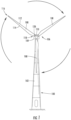
- FIG. 1 illustrates a diagrammatic view of a horizontal-axis wind turbine generator (WTG) 100.
- the WTG 100 typically includes a tower 102 and a nacelle 104 located at the top of the tower 102.
- a wind turbine rotor 106 may be connected with the nacelle 104 through a low speed shaft extending out of the nacelle 104.
- the wind turbine rotor 106 includes three rotor blades 108 mounted on a common hub 110, but may include any suitable number of blades, such as two, four, five, or more blades.
- the blade 108 typically has an aerodynamic shape with a leading edge 112 for facing into the wind, a trailing edge 114 at the opposite end of a chord for the blade 108, a tip 116, and a root 118 for attaching to the hub 110 in any suitable manner.
- the blades 108 may be connected to the hub 110 using pitch bearings 120 such that each blade 108 may be rotated around its longitudinal axis to adjust the blade's pitch.
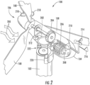
- Figure 2 illustrates a diagrammatic view of typical components internal to the nacelle 104 and tower 102 of the WTG 100.
- the rotor 106 spins and rotates a low-speed shaft 202.
- Gears in a gearbox 204 mechanically convert the low rotational speed of the low-speed shaft 202 into a relatively high rotational speed of a high-speed shaft 208 suitable for generating electricity using a generator 206.
- the WTG 100 may also include a braking system 212 for emergency shutdown situations and/or for locking the rotor in a required position.
- a controller 210 may sense the rotational speed of one or both of the shafts 202, 208.
- the controller 210 may receive inputs from an anemometer 214 (providing wind speed) and/or a wind vane 216 (providing wind direction). Based on information received, the controller 210 may send a control signal to one or more of the blades 108 in an effort to adjust the pitch 218 of the blades. By adjusting the pitch 218 of the blades with respect to the wind direction, the rotational speed of the rotor (and therefore, the shafts 202, 208) may be increased or decreased.
- the controller 210 may send a control signal to an assembly comprising a yaw motor 220 and a yaw drive 222 to rotate the nacelle 104 with respect to the tower 102, such that the rotor 106 may be positioned to face more (or, in certain circumstances, less) upwind.
- FIG. 3 is a schematic view of a control system 300 for one or more ETH panels 302 inside the WTG 100.
- the control system 300 may include a plurality of blade control and power distribution boxes 304, hub control and power distribution box 306, a slip ring 314, a power source 316, and a system controller 308.
- the one or more ETH panels 302 may be embedded in each blade 108 and may be controlled by blade control and power distribution boxes 304 located in the root 118 of each blade 108.
- blade control and power distribution boxes 304 for each blade 108.
- the one or more ETH panels 302 cover the entire blade 108 except for the root 118.
- Electrical power may be supplied to the one or more ETH panels 302 from blade power and distribution box 304 located in the blade root.
- the blade power and distribution box 304 may include relays for switching on and off the one or more ETH panels 302 in each blade 108.
- the blade power and distribution box 304 may also include lightning protection components. From the blade power and distribution box 304, power cables are routed to each ETH panel 302.
- the WTG 100 includes three blades and three power cables 307, and each power cable 307 connects the hub power and distribution box 306 to a corresponding blade power and distribution box 304 located in a corresponding blade 108.
- the hub control and power distribution box 306 may be electrically connected a slip ring 314 located inside the nacelle 104.
- the slip ring 314 may be electrically connected to a power source 316 located inside the nacelle 104.
- the power source 316 may include a circuit breaker switch to allow the system to be de-energized. Electrical power may be supplied from the power source 316 through the hub interface of the nacelle 104 via the slip ring 314 and may be supplied to the one or more ETH panels 302 in each blade 108 via the slip ring 314, the hub control and power distribution box 306, and the blade control and power distribution box 304.
- the control and operation of the control system 300 may be achieved by remote connection via the system controller 308 and communication through the slip ring 314.
- the control system 300 may utilize duty cycling (i.e., switching on and off relays over a period of time) to achieve power distribution across the one or more ETH panels 302 in each blade 108. During severe icing conditions ideally all of the ETH panels 302 embedded in the blades 108 should be switched on continuously.
- the slip ring 314 may have a power or current constraint which will restrict the energy drawn from the power source 316 to the ETH Panels 302. To maximize the potential power available to the ETH panels 302, the control system 300 will focus on a fixed and predetermined set of zones having combined energy consumption less than the capabilities of the slip ring 314.
- FIG 4A is a perspective view of the blade 108 showing a portion of the embedded ETH panel 302.
- the ETH panel 302 may be embedded in the blade 108, such as between a first layer 402 and a second layer 404 of the blade 108.
- the ETH panel 302 may be any suitable resistive heating element.
- each ETH panel 302 includes a carbon mesh 406 and a busbar 408 disposed across the carbon mesh 406 for supplying power to the carbon mesh 406, as shown in Figure 4B .
- FIG. 5A illustrates an example of conventional system 500 for controlling temperature of a blade in a wind turbine.
- the system 500 includes an input 502, control logic 504, and output 506.
- the input 502 is provided to the control logic 504.
- the input 502 is a current temperature measured by temperature sensors positioned on each ETH panel in each blade.
- the control logic 504 determines whether the temperature provided by the input 502 exceeds a target temperature.
- the control logic 504 Based on this determination, the control logic 504 generates an output 506. If the control logic 504 determines that the temperature provided by input 502 exceeds the target temperature, then the control logic 504 generates the output 506 to stop providing energy to the ETH panels in the blade. If, however, the control logic 504 determines that the temperature does not exceed the target temperature, then the control logic 504 generates an output 506 that continues to provide energy to the ETH elements.
- the input 502 continually provides temperature readings to the control logic 504, which, in turn, continually generates an output 506. This continual process creates a feedback loop 508 between the control logic 504 and the input 502 so that the system continuously monitors the temperature of the ETH elements in the blade.
- Figure 5B illustrates an improved system 510 for controlling temperature of a blade in a wind turbine system, according to one example.
- the system 510 includes an input 512, control logic 514, and output 516.
- the input 512 is provided to the control logic 514.
- the input 512 may include information such as physical conditions of the blade and ambient conditions surrounding the blade.
- the control logic 514 takes the input 512 and generates an output 516.
- the output 516 may be an amount of energy to be provided to the ETH panel.
- the input 512 continually provides information to the control logic 514, which in turn continually generates output 516.
- the system 510 differs from the conventional system 500 by removing the need for a feedback loop.
- the temperature of a blade in a wind turbine may be controlled without the need of temperature sensors on each ETH panel, which decreases the complexity of the controller hardware.
- Figure 6 illustrates a graph 600 depicting a relationship between a temperature of an object and an amount of time that object is heated.
- time is depicted along the x-axis 602 and temperature is depicted along the y-axis 604.
- Line 606 designates an initial temperature of an object.
- Line 608 designates an end temperature of the object.
- the heating curve 610 plateaus.
- the ending temperature is the point at which the temperature of the object begins to plateau, known as the equilibrium point.
- System 510 is configured to create a function that takes inputs 512 to generate an output 516 such that the blade may reach a target temperature at the end temperature line 608. This may be done by tailoring a function to be dependent on ambient conditions surrounding the blade and physical conditions of the blade to generate a minimum amount of energy such that the target temperature occurs at the end temperature line 608 in graph 600, i.e., where the heating curve plateaus.
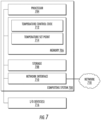
- FIG. 7 illustrates one example of a computing system 700, such as system controller 308, which is configured to carry out a method for controlling the temperature of a blade in a wind turbine system.
- the computing system 700 includes a processor 704, a memory 706, storage 708, and a network interface 710.
- the processor 704 is included to be representative of a single processor, multiple processors, a single processor having multiple processing cores, and the like.
- the storage 708 may be a hard disk drive or a solid state drive or embedded RAM. Although shown as a single unit, the storage 708 may be a combination of fixed and/or removable storage devices, such as fixed drives, removable memory cards, optical storage, network attached storage (NAS), or storage-area-network (SAN).
- NAS network attached storage
- SAN storage-area-network
- the temperature control code 712 includes a function that generates a minimum amount of energy to be provided to each ETH panel such that the desired end temperatures stored in the temperature set points 714 may be reached.
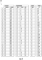
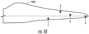
- the function may generate a minimum amount of energy that is to be provided to the ETH panel at Point A that differs from the minimum amount of energy that is to be provided to the ETH panel at Point B. This may be due to a variety of factors, such as differences in radius positions, RPMs, chord positions, and the like.
- E represents the energy to be provided to the ETH panel
- T start represents the starting temperature
- T max represents the plateau or target temperature
- WS represents the wind speed over the surface of the blade as a function of the radius position (R), chord position (C), and rotor speed (RPM)
- LWC represents the liquid water content of the air.
- FIG. 9 is a flow diagram 900 for controlling the temperature of a blade in a wind turbine system, according to one embodiment.
- the flow diagram 900 begins at step 902.
- a user sets a target temperature for a given location in the blade.
- the target temperature for a given location in the blade may correspond to a given heating element, such as an ETH panel.
- the target temperature is the temperature at which the heating curve for that location of the blade will plateau, as exemplified in graph 600.
- a minimum amount of energy to be provided to the ETH panel is outputted.
- the minimum amount of energy outputted is the minimum amount of energy required to reach the target temperature that was set in step 902.
- the amount of energy generated is less than the amount of energy needed to reach a material safety limit.
- the energy provided to the ETH panel is adjusted based on the minimum amount of energy generated in step 904 to reach the target temperature.
- the inputs of the functions are changed.
- the minimum amount of energy required for the ETH panel to reach the target temperature is continually updated.
- Adjusting the amount of energy provided to the ETH panel includes not only adjusting the wattage provided to the ETH panel, but also the duration that wattage is provided to the ETH panel.
- each block in the flowchart or block diagrams may represent a module, segment, or portion of code, which comprises one or more executable instructions for implementing the specified logical function(s).
- the functions noted in the block may occur out of the order noted in the figures. For example, two blocks shown in succession may, in fact, be executed substantially concurrently, or the blocks may sometimes be executed in the reverse order, depending upon the functionality involved.
Landscapes
- Engineering & Computer Science (AREA)
- Life Sciences & Earth Sciences (AREA)
- Sustainable Development (AREA)
- Sustainable Energy (AREA)
- Chemical & Material Sciences (AREA)
- Combustion & Propulsion (AREA)
- Mechanical Engineering (AREA)
- General Engineering & Computer Science (AREA)
- Wind Motors (AREA)
Claims (15)
- Procédé de commande d'une température d'une pale dans un système d'éolienne, comprenant :le réglage d'une température cible de la pale ;l'entrée de conditions physiques de la pale et de conditions ambiantes autour de la pale dans un processeur ;la sortie d'une quantité minimale d'énergie à fournir à un élément chauffant de la pale, requise pour atteindre la température cible en adaptant une fonction pour qu'elle dépende des conditions physiques et conditions ambiantes de sorte que la température cible se produit au niveau d'une ligne de température finale (608), où une courbe de chauffage pour la pale atteint un plateau ; etl'ajustement de l'énergie fournie à l'élément chauffant pour atteindre la température cible.
- Procédé selon la revendication 1, dans lequel les conditions ambiantes incluent la température d'air extérieur et la vitesse de vent.
- Procédé selon la revendication 1 ou 2, dans lequel les conditions ambiantes incluent en outre une teneur en eau liquide de l'air.
- Procédé selon une quelconque revendication précédente, dans lequel les conditions physiques incluent des rotations par minute de la pale, un angle de la pale, une position de rayon de la pale, une position de corde de la pale, et un coefficient de matériau de la pale.
- Procédé selon une quelconque revendication précédente, dans lequel la température cible ne dépasse pas une limite de sécurité de matériau de la pale.
- Procédé selon une quelconque revendication précédente, comprenant en outre :l'entrée continue de conditions ambiantes et physiques mises à jour ;la sortie de la quantité minimale d'énergie pour atteindre la température cible sur la base des conditions ambiantes et physiques mises à jour ; etl'ajustement de l'énergie requise pour atteindre la température cible.
- Procédé selon une quelconque revendication précédente, dans lequel l'ajustement de l'énergie comprend :
l'ajustement d'une durée pendant laquelle une quantité d'énergie est fournie à l'élément chauffant. - Système, comprenant :un processeur ; etun mémoire stockant un code de programme, qui, lorsqu'il est exécuté sur le processeur met en oeuvre une opération pour commander une température d'une pale dans un système d'éolienne, l'opération comprenant :le réglage d'une température cible de la pale ;l'entrée de conditions physiques de la pale et de conditions ambiantes autour de la pale dans le processeur ;la sortie d'une quantité minimale d'énergie à un élément chauffant de la pale, requise pour atteindre la température cible en adaptant une fonction pour qu'elle dépende des conditions physiques et conditions ambiantes de sorte que la température cible se produit au niveau d'une ligne de température finale (608), où une courbe de chauffage pour la pale atteint un plateau ; etl'ajustement de l'énergie fournie à l'élément chauffant pour atteindre la température cible.
- Système selon la revendication 8, dans lequel les conditions ambiantes incluent la température d'air extérieur et la vitesse de vent.
- Système selon la revendication 8 ou 9, dans lequel les conditions ambiantes incluent en outre une teneur en eau liquide de l'air.
- Système selon l'une quelconque des revendications 8 à 10, dans lequel les conditions physiques incluent des rotations par minute de la pale, un angle de la pale, une position de rayon de la pale, une position de corde de la pale, et un coefficient de matériau de la pale.
- Système selon l'une quelconque des revendications 8 à 11, dans lequel la température cible ne dépasse pas une limite de sécurité de matériau de la pale.
- Système selon l'une quelconque des revendications 8 à 12, comprenant en outre :l'entrée continue de conditions ambiantes et physiques mises à jour ;la sortie de la quantité minimale d'énergie pour atteindre la température cible sur la base des conditions ambiantes et physiques mises à jour ; etl'ajustement de l'énergie requise pour atteindre la température cible.
- Système selon l'une quelconque des revendications 8 à 13, dans lequel l'ajustement de l'énergie comprend :
l'ajustement d'une durée pendant laquelle la quantité d'énergie est fournie à l'élément chauffant. - Support de stockage lisible par ordinateur sur lequel sont stockées des instructions qui, lorsqu'elles sont exécutées par un processeur, amènent le processeur à mettre en oeuvre un procédé de commande d'une température d'une pale dans un système d'éolienne, le procédé comprenant :le réglage d'une température cible de la pale ;l'entrée de conditions physiques de la pale et de conditions ambiantes autour de la pale dans un processeur ;la sortie d'une quantité minimale d'énergie à un élément chauffant de la pale, requise pour atteindre la température cible en adaptant une fonction pour qu'elle dépende des conditions physiques et conditions ambiantes de sorte que la température cible se produit au niveau d'une ligne de température finale (608), où une courbe de chauffage pour la pale atteint un plateau ; etl'ajustement de l'énergie fournie à l'élément chauffant pour atteindre la température cible.
Applications Claiming Priority (2)
| Application Number | Priority Date | Filing Date | Title |
|---|---|---|---|
| DKPA201670180 | 2016-03-31 | ||
| PCT/DK2017/050097 WO2017167346A1 (fr) | 2016-03-31 | 2017-03-30 | Commande d'éléments chauffants dans un système de turbine éolienne |
Publications (3)
| Publication Number | Publication Date |
|---|---|
| EP3436697A1 EP3436697A1 (fr) | 2019-02-06 |
| EP3436697C0 EP3436697C0 (fr) | 2023-08-02 |
| EP3436697B1 true EP3436697B1 (fr) | 2023-08-02 |
Family
ID=59962636
Family Applications (1)
| Application Number | Title | Priority Date | Filing Date |
|---|---|---|---|
| EP17715905.0A Active EP3436697B1 (fr) | 2016-03-31 | 2017-03-30 | Commande d'éléments chauffants dans un système de turbine éolienne |
Country Status (5)
| Country | Link |
|---|---|
| US (1) | US10927821B2 (fr) |
| EP (1) | EP3436697B1 (fr) |
| CN (1) | CN108884813A (fr) |
| CA (1) | CA3017775C (fr) |
| WO (1) | WO2017167346A1 (fr) |
Families Citing this family (12)
| Publication number | Priority date | Publication date | Assignee | Title |
|---|---|---|---|---|
| CN108884813A (zh) | 2016-03-31 | 2018-11-23 | 维斯塔斯风力系统集团公司 | 控制风力涡轮机系统中的加热元件 |
| WO2018001435A1 (fr) * | 2016-06-30 | 2018-01-04 | Vestas Wind Systems A/S | Barres omnibus dans un agencement d'empilage |
| EP3559457B1 (fr) | 2016-12-22 | 2020-08-12 | Vestas Wind Systems A/S | Régulation de température basée sur la prévision météorologique |
| US10442539B2 (en) * | 2017-05-12 | 2019-10-15 | Bell Helicopter Textron Inc. | Anti-ice system for thermally fragile materials |
| WO2019001658A1 (fr) * | 2017-06-30 | 2019-01-03 | Vestas Wind Systems A/S | Diagnostic de défaut de contact électrique |
| US20220003210A1 (en) * | 2018-10-26 | 2022-01-06 | Vestas Wind Systems A/S | Controller for a wind farm |
| CA3123700A1 (fr) * | 2018-12-20 | 2020-06-25 | Vestas Wind Systems A/S | Perfectionnements apportes aux systemes de degivrage de pales d'eolienne |
| PT3792487T (pt) * | 2019-09-16 | 2022-10-11 | Siemens Gamesa Renewable Energy Innovation & Technology SL | Proteção contra raios de pá de turbina eólica com componentes ativos |
| US20220195993A1 (en) * | 2020-12-23 | 2022-06-23 | Borealis Wind Inc. | Wind turbine ice protection system |
| CA3234024A1 (fr) * | 2021-10-07 | 2023-04-13 | Kjell Lindskog | Procede destine a empecher la formation de glace au niveau d'une pale d'une eolienne |
| EP4194685A1 (fr) * | 2021-12-07 | 2023-06-14 | General Electric Renovables España S.L. | Procédé de fonctionnement d'une éolienne et éolienne |
| GR1010560B (el) * | 2023-01-26 | 2023-10-25 | Βασιλειος Νικολαου Ορφανος | Συστημα προστασιας απο πτωση παγου τουλαχιστον μιας συσκευης εποπτειας κινουμενων αντικειμενων και/ή τουλαχιστον μιας συσκευης αποτροπης προσκρουσης κινουμενων αντικειμενων τοποθετημενης στον πυλωνα ανεμογεννητριας |
Family Cites Families (14)
| Publication number | Priority date | Publication date | Assignee | Title |
|---|---|---|---|---|
| FR2863586B1 (fr) | 2003-12-12 | 2007-01-19 | Eurocopter France | Dispositif de degivrage/antigivrage modulaire d'une surface aerodynamique. |
| US20100119370A1 (en) * | 2009-11-17 | 2010-05-13 | Modi Vivendi As | Intelligent and optimized wind turbine system for harsh environmental conditions |
| FI20110232L (fi) | 2011-07-05 | 2013-01-11 | Hafmex Oy | Lämmitettävä tuulivoimalan roottori |
| EP2805045B1 (fr) * | 2012-01-20 | 2018-03-14 | Vestas Wind Systems A/S | Procédé de dégivrage d'une pale de turbine éolienne |
| CN103034271B (zh) | 2013-01-15 | 2016-03-16 | 天津工业大学 | 风力发电机叶片的防凝冻抗积冰电控装置 |
| US9488157B2 (en) * | 2013-03-15 | 2016-11-08 | Frontier Wind, Llc | Blade balancing |
| DE102013206039A1 (de) | 2013-04-05 | 2014-10-09 | Wobben Properties Gmbh | Windenergieanlage und Verfahren zum Betreiben einer Windenergieanlage |
| CN103291560A (zh) | 2013-04-26 | 2013-09-11 | 湘电新能源有限公司 | 一种碳晶防冰的方法和采用该方法的风力发电机防冰系统 |
| EP2826993B1 (fr) * | 2013-07-17 | 2017-04-12 | ADIOS Patent GmbH | Procédé de dégivrage des pales de rotor d'une installation éolienne et système de dégivrage des pales de rotor d'une installation éolienne |
| CN203452981U (zh) | 2013-07-22 | 2014-02-26 | 广西银河风力发电有限公司 | 一种带有叶片热气抗凝冻系统的风机 |
| ES2642417T3 (es) * | 2014-09-19 | 2017-11-16 | Nordex Energy Gmbh | Procedimiento para el funcionamiento de una planta de energía eólica con un dispositivo calefactor de pala de rotor |
| DE102015000636A1 (de) | 2015-01-22 | 2016-07-28 | Senvion Gmbh | Verfahren zum Enteisen eines Rotorblatts einer Windenergieanlage |
| CA3008043C (fr) * | 2016-03-01 | 2019-03-12 | 9719245 Canada Inc. | Systemes et procedes de degivrage de pale d'eolienne |
| CN108884813A (zh) | 2016-03-31 | 2018-11-23 | 维斯塔斯风力系统集团公司 | 控制风力涡轮机系统中的加热元件 |
-
2017
- 2017-03-30 CN CN201780020931.XA patent/CN108884813A/zh active Pending
- 2017-03-30 WO PCT/DK2017/050097 patent/WO2017167346A1/fr active Application Filing
- 2017-03-30 CA CA3017775A patent/CA3017775C/fr active Active
- 2017-03-30 US US16/090,105 patent/US10927821B2/en active Active
- 2017-03-30 EP EP17715905.0A patent/EP3436697B1/fr active Active
Also Published As
| Publication number | Publication date |
|---|---|
| CA3017775A1 (fr) | 2017-10-05 |
| US20190113025A1 (en) | 2019-04-18 |
| US10927821B2 (en) | 2021-02-23 |
| WO2017167346A1 (fr) | 2017-10-05 |
| CA3017775C (fr) | 2020-08-25 |
| EP3436697C0 (fr) | 2023-08-02 |
| EP3436697A1 (fr) | 2019-02-06 |
| CN108884813A (zh) | 2018-11-23 |
Similar Documents
| Publication | Publication Date | Title |
|---|---|---|
| EP3436697B1 (fr) | Commande d'éléments chauffants dans un système de turbine éolienne | |
| EP3559457B1 (fr) | Régulation de température basée sur la prévision météorologique | |
| EP3436698B1 (fr) | Contrôle de condition et commande d'éléments chauffants dans des turbines éoliennes | |
| EP3203066B1 (fr) | Système et procédé de dégivrer une lame d'éolienne | |
| US10495062B2 (en) | Power ramping a turbine from a low-power mode | |
| EP3387253B1 (fr) | Commande de production d'énergie d'éolienne à l'intérieur d'une limite de taux d'accroissement de puissance pour centrale éolienne | |
| EP3032095A1 (fr) | Procédé de fonctionnement d'une éolienne et éoliennes | |
| EP3899267B1 (fr) | Perfectionnements apportés aux systèmes de dégivrage de pales d'éolienne | |
| CA2977926C (fr) | Regulation de puissance dans une methode de demarrage d'une eolienne | |
| EP2607688B1 (fr) | Procédé de commande d'éolienne | |
| CA2888726C (fr) | Regulation de temperature d'aube de turbine pour la reduction du bruit | |
| WO2017190747A1 (fr) | Génération et stockage d'énergie dans le moyeu pour antigivrage de pales d'éolienne | |
| CN108644072B (zh) | 风力发电机组桨叶的除冰装置及其方法 | |
| KR101411478B1 (ko) | 풍력 발전기 |
Legal Events
| Date | Code | Title | Description |
|---|---|---|---|
| STAA | Information on the status of an ep patent application or granted ep patent |
Free format text: STATUS: UNKNOWN |
|
| STAA | Information on the status of an ep patent application or granted ep patent |
Free format text: STATUS: THE INTERNATIONAL PUBLICATION HAS BEEN MADE |
|
| PUAI | Public reference made under article 153(3) epc to a published international application that has entered the european phase |
Free format text: ORIGINAL CODE: 0009012 |
|
| STAA | Information on the status of an ep patent application or granted ep patent |
Free format text: STATUS: REQUEST FOR EXAMINATION WAS MADE |
|
| 17P | Request for examination filed |
Effective date: 20181026 |
|
| AK | Designated contracting states |
Kind code of ref document: A1 Designated state(s): AL AT BE BG CH CY CZ DE DK EE ES FI FR GB GR HR HU IE IS IT LI LT LU LV MC MK MT NL NO PL PT RO RS SE SI SK SM TR |
|
| AX | Request for extension of the european patent |
Extension state: BA ME |
|
| DAV | Request for validation of the european patent (deleted) | ||
| DAX | Request for extension of the european patent (deleted) | ||
| STAA | Information on the status of an ep patent application or granted ep patent |
Free format text: STATUS: EXAMINATION IS IN PROGRESS |
|
| 17Q | First examination report despatched |
Effective date: 20200730 |
|
| STAA | Information on the status of an ep patent application or granted ep patent |
Free format text: STATUS: EXAMINATION IS IN PROGRESS |
|
| STAA | Information on the status of an ep patent application or granted ep patent |
Free format text: STATUS: EXAMINATION IS IN PROGRESS |
|
| GRAP | Despatch of communication of intention to grant a patent |
Free format text: ORIGINAL CODE: EPIDOSNIGR1 |
|
| STAA | Information on the status of an ep patent application or granted ep patent |
Free format text: STATUS: GRANT OF PATENT IS INTENDED |
|
| INTG | Intention to grant announced |
Effective date: 20220721 |
|
| GRAJ | Information related to disapproval of communication of intention to grant by the applicant or resumption of examination proceedings by the epo deleted |
Free format text: ORIGINAL CODE: EPIDOSDIGR1 |
|
| STAA | Information on the status of an ep patent application or granted ep patent |
Free format text: STATUS: EXAMINATION IS IN PROGRESS |
|
| GRAJ | Information related to disapproval of communication of intention to grant by the applicant or resumption of examination proceedings by the epo deleted |
Free format text: ORIGINAL CODE: EPIDOSDIGR1 |
|
| GRAP | Despatch of communication of intention to grant a patent |
Free format text: ORIGINAL CODE: EPIDOSNIGR1 |
|
| INTC | Intention to grant announced (deleted) | ||
| GRAP | Despatch of communication of intention to grant a patent |
Free format text: ORIGINAL CODE: EPIDOSNIGR1 |
|
| STAA | Information on the status of an ep patent application or granted ep patent |
Free format text: STATUS: GRANT OF PATENT IS INTENDED |
|
| INTG | Intention to grant announced |
Effective date: 20230210 |
|
| GRAS | Grant fee paid |
Free format text: ORIGINAL CODE: EPIDOSNIGR3 |
|
| GRAA | (expected) grant |
Free format text: ORIGINAL CODE: 0009210 |
|
| STAA | Information on the status of an ep patent application or granted ep patent |
Free format text: STATUS: THE PATENT HAS BEEN GRANTED |
|
| AK | Designated contracting states |
Kind code of ref document: B1 Designated state(s): AL AT BE BG CH CY CZ DE DK EE ES FI FR GB GR HR HU IE IS IT LI LT LU LV MC MK MT NL NO PL PT RO RS SE SI SK SM TR |
|
| REG | Reference to a national code |
Ref country code: GB Ref legal event code: FG4D |
|
| REG | Reference to a national code |
Ref country code: CH Ref legal event code: EP |
|
| REG | Reference to a national code |
Ref country code: DE Ref legal event code: R096 Ref document number: 602017072086 Country of ref document: DE |
|
| REG | Reference to a national code |
Ref country code: IE Ref legal event code: FG4D |
|
| U01 | Request for unitary effect filed |
Effective date: 20230823 |
|
| U07 | Unitary effect registered |
Designated state(s): AT BE BG DE DK EE FI FR IT LT LU LV MT NL PT SE SI Effective date: 20230829 |
|
| REG | Reference to a national code |
Ref country code: NO Ref legal event code: T2 Effective date: 20230802 |
|
| PG25 | Lapsed in a contracting state [announced via postgrant information from national office to epo] |
Ref country code: GR Free format text: LAPSE BECAUSE OF FAILURE TO SUBMIT A TRANSLATION OF THE DESCRIPTION OR TO PAY THE FEE WITHIN THE PRESCRIBED TIME-LIMIT Effective date: 20231103 |
|
| PG25 | Lapsed in a contracting state [announced via postgrant information from national office to epo] |
Ref country code: IS Free format text: LAPSE BECAUSE OF FAILURE TO SUBMIT A TRANSLATION OF THE DESCRIPTION OR TO PAY THE FEE WITHIN THE PRESCRIBED TIME-LIMIT Effective date: 20231202 |
|
| PG25 | Lapsed in a contracting state [announced via postgrant information from national office to epo] |
Ref country code: RS Free format text: LAPSE BECAUSE OF FAILURE TO SUBMIT A TRANSLATION OF THE DESCRIPTION OR TO PAY THE FEE WITHIN THE PRESCRIBED TIME-LIMIT Effective date: 20230802 Ref country code: IS Free format text: LAPSE BECAUSE OF FAILURE TO SUBMIT A TRANSLATION OF THE DESCRIPTION OR TO PAY THE FEE WITHIN THE PRESCRIBED TIME-LIMIT Effective date: 20231202 Ref country code: HR Free format text: LAPSE BECAUSE OF FAILURE TO SUBMIT A TRANSLATION OF THE DESCRIPTION OR TO PAY THE FEE WITHIN THE PRESCRIBED TIME-LIMIT Effective date: 20230802 Ref country code: GR Free format text: LAPSE BECAUSE OF FAILURE TO SUBMIT A TRANSLATION OF THE DESCRIPTION OR TO PAY THE FEE WITHIN THE PRESCRIBED TIME-LIMIT Effective date: 20231103 |
|
| PG25 | Lapsed in a contracting state [announced via postgrant information from national office to epo] |
Ref country code: PL Free format text: LAPSE BECAUSE OF FAILURE TO SUBMIT A TRANSLATION OF THE DESCRIPTION OR TO PAY THE FEE WITHIN THE PRESCRIBED TIME-LIMIT Effective date: 20230802 |
|
| PG25 | Lapsed in a contracting state [announced via postgrant information from national office to epo] |
Ref country code: ES Free format text: LAPSE BECAUSE OF FAILURE TO SUBMIT A TRANSLATION OF THE DESCRIPTION OR TO PAY THE FEE WITHIN THE PRESCRIBED TIME-LIMIT Effective date: 20230802 |
|
| PG25 | Lapsed in a contracting state [announced via postgrant information from national office to epo] |
Ref country code: SM Free format text: LAPSE BECAUSE OF FAILURE TO SUBMIT A TRANSLATION OF THE DESCRIPTION OR TO PAY THE FEE WITHIN THE PRESCRIBED TIME-LIMIT Effective date: 20230802 Ref country code: RO Free format text: LAPSE BECAUSE OF FAILURE TO SUBMIT A TRANSLATION OF THE DESCRIPTION OR TO PAY THE FEE WITHIN THE PRESCRIBED TIME-LIMIT Effective date: 20230802 Ref country code: ES Free format text: LAPSE BECAUSE OF FAILURE TO SUBMIT A TRANSLATION OF THE DESCRIPTION OR TO PAY THE FEE WITHIN THE PRESCRIBED TIME-LIMIT Effective date: 20230802 Ref country code: CZ Free format text: LAPSE BECAUSE OF FAILURE TO SUBMIT A TRANSLATION OF THE DESCRIPTION OR TO PAY THE FEE WITHIN THE PRESCRIBED TIME-LIMIT Effective date: 20230802 Ref country code: SK Free format text: LAPSE BECAUSE OF FAILURE TO SUBMIT A TRANSLATION OF THE DESCRIPTION OR TO PAY THE FEE WITHIN THE PRESCRIBED TIME-LIMIT Effective date: 20230802 |
|
| PGFP | Annual fee paid to national office [announced via postgrant information from national office to epo] |
Ref country code: GB Payment date: 20240319 Year of fee payment: 8 |
|
| U20 | Renewal fee paid [unitary effect] |
Year of fee payment: 8 Effective date: 20240326 |