EP3436636B1 - Masked coating blade - Google Patents
Masked coating blade Download PDFInfo
- Publication number
- EP3436636B1 EP3436636B1 EP17714237.9A EP17714237A EP3436636B1 EP 3436636 B1 EP3436636 B1 EP 3436636B1 EP 17714237 A EP17714237 A EP 17714237A EP 3436636 B1 EP3436636 B1 EP 3436636B1
- Authority
- EP
- European Patent Office
- Prior art keywords
- deposit
- wear
- coating
- masking
- resistant
- Prior art date
- Legal status (The legal status is an assumption and is not a legal conclusion. Google has not performed a legal analysis and makes no representation as to the accuracy of the status listed.)
- Active
Links
Images

Classifications
-
- B—PERFORMING OPERATIONS; TRANSPORTING
- B05—SPRAYING OR ATOMISING IN GENERAL; APPLYING FLUENT MATERIALS TO SURFACES, IN GENERAL
- B05C—APPARATUS FOR APPLYING FLUENT MATERIALS TO SURFACES, IN GENERAL
- B05C11/00—Component parts, details or accessories not specifically provided for in groups B05C1/00 - B05C9/00
- B05C11/02—Apparatus for spreading or distributing liquids or other fluent materials already applied to a surface ; Controlling means therefor; Control of the thickness of a coating by spreading or distributing liquids or other fluent materials already applied to the coated surface
- B05C11/04—Apparatus for spreading or distributing liquids or other fluent materials already applied to a surface ; Controlling means therefor; Control of the thickness of a coating by spreading or distributing liquids or other fluent materials already applied to the coated surface with blades
- B05C11/045—Apparatus for spreading or distributing liquids or other fluent materials already applied to a surface ; Controlling means therefor; Control of the thickness of a coating by spreading or distributing liquids or other fluent materials already applied to the coated surface with blades characterised by the blades themselves
-
- D—TEXTILES; PAPER
- D21—PAPER-MAKING; PRODUCTION OF CELLULOSE
- D21G—CALENDERS; ACCESSORIES FOR PAPER-MAKING MACHINES
- D21G3/00—Doctors
- D21G3/005—Doctor knifes
-
- D—TEXTILES; PAPER
- D21—PAPER-MAKING; PRODUCTION OF CELLULOSE
- D21H—PULP COMPOSITIONS; PREPARATION THEREOF NOT COVERED BY SUBCLASSES D21C OR D21D; IMPREGNATING OR COATING OF PAPER; TREATMENT OF FINISHED PAPER NOT COVERED BY CLASS B31 OR SUBCLASS D21G; PAPER NOT OTHERWISE PROVIDED FOR
- D21H23/00—Processes or apparatus for adding material to the pulp or to the paper
- D21H23/02—Processes or apparatus for adding material to the pulp or to the paper characterised by the manner in which substances are added
- D21H23/22—Addition to the formed paper
- D21H23/32—Addition to the formed paper by contacting paper with an excess of material, e.g. from a reservoir or in a manner necessitating removal of applied excess material from the paper
- D21H23/34—Knife or blade type coaters
-
- D—TEXTILES; PAPER
- D21—PAPER-MAKING; PRODUCTION OF CELLULOSE
- D21H—PULP COMPOSITIONS; PREPARATION THEREOF NOT COVERED BY SUBCLASSES D21C OR D21D; IMPREGNATING OR COATING OF PAPER; TREATMENT OF FINISHED PAPER NOT COVERED BY CLASS B31 OR SUBCLASS D21G; PAPER NOT OTHERWISE PROVIDED FOR
- D21H25/00—After-treatment of paper not provided for in groups D21H17/00 - D21H23/00
- D21H25/08—Rearranging applied substances, e.g. metering, smoothing; Removing excess material
- D21H25/10—Rearranging applied substances, e.g. metering, smoothing; Removing excess material with blades
Definitions
- the present invention relates to a coating blade for application of coating color to a fibrous web.
- Coating blades are known in the art also as doctor blades or scrapers, all of which will be referred to herein as coating blades.
- the coating blade is typically constituted by a steel substrate onto which a deposit has been applied.
- an excess of coating color liquid is applied to the surface of the paper and subsequently doctored off using the coating blade.
- the paper is usually supplied as a web, which is supported and fed by a backing roll during the application and doctoring of coating color.
- the coating blade applies a pressure on the coating color liquid. Pigment particles in the coating color fluid subject the coating blade to both abrasive and erosive wear.
- Wear-resistant deposits are intrinsically hard and/or rigid, thus affecting the flexibility of the coating blade.
- the tendency in the art is to develop harder and more wear-resistant materials.
- the global amount of applied material tends to increase. This strongly rigidifies the structure, resulting in limited blade flexibility (in the machine direction and in the cross/transversal direction).
- the coating blade is sufficiently flexible in order to adapt appropriately, at high machine speed, to the topography of the paper to be coated.
- the wear-resistant deposit normally covers only a relatively narrow area along a longitudinal edge of the substrate.
- JP 2006/161713 discloses a coating blade provided with a wear-resistant deposit for the application of coating color to paper.
- the wear-resistant deposit has a tapered shape giving a smooth transition between the surface of the wear-resistant deposit and the surface of the substrate.
- Residues of coating color typically having a high pigment concentration in a surrounding latex phase, tend however to stick to the deposit surface or blade surface upstream of the blade tip. Such residues, or “stickies”, cause streaks in the paper coating and thus lead to quality issues.
- WO 2010/133762 A1 discloses a doctor blade having a multiple layer coating.
- US 2014/0137361 A1 discloses a cleaning scraper having a coating that is formed with a first coating layer and a second coating layer arranged on the first coating layer.
- US 2005/0172889 A1 discloses a coating blade having a sacrificial layer covering at least an edge section thereof.
- the masking deposit thus hides a part of the substrate from contact with the coating color. It is contemplated that the masking deposit has a lower elastic modulus than the wear-resistant deposit.
- the high requirements of paper coating can be met in that the coating blade during use has a long life-time, and provides a stable doctoring effect producing coated paper with excellent surface quality.
- the masking deposit is thus arranged on the substrate next to and joining the wear-resistant deposit. It is contemplated that the masking deposit extends over the substrate, next to the wear-resistant deposit, in a direction perpendicular to the longitudinal edge, for a substantially larger distance than the thickness of the masking deposit, such as for more than about 5 or more than about 10 times its thickness.
- the masking deposit consists of one or more layers.
- the masking deposit has a lower elastic modulus than the substrate.
- the substrate typically has an elastic modulus in the range of about 170-220 GPa.
- the masking deposit typically has an elastic modulus of less than about 50 GPa, preferably less than about 20 GPa.
- the wear-resistant deposit typically has a higher elastic modulus than the substrate, such as higher than 220 GPa.
- the masking deposit may comprise a polymer material.
- the polymer material may be a polyurethane material, typically an ester based, ether based or solvent based polyurethane material.
- the polymer material may alternatively be a polyepoxide, polysiloxane or acrylic polymer. Additives or fillers may be used to improve the mechanical properties of the masking deposit, without affecting negatively the elastic modulus of the masking deposit and/or the flexibility of the coating blade.
- the masking deposit may taper towards the surface of the substrate.
- a tapered shape is preferred in order to minimize the amount of material used for the masking deposit.
- the tapered shape additionally improves the fluid dynamic properties of the coating color.
- the masking deposit may thus taper from a larger thickness near the wear-resistant deposit to a smaller thickness more remote from the wear-resistant deposit.
- the larger thickness is typically substantially similar to the thickness of the wear-resistant deposit.
- the masking deposit may taper at a constant rate from the larger thickness to the smaller thickness. The thickness of the masking deposit will thus decrease following a straight path from the larger thickness to the smaller thickness. Typically, however, the masking deposit will taper at varying rates from the larger thickness to the smaller thickness.
- the thickness of the masking deposit may decrease strongly near the wear-resistant deposit and weakly more remote from the wear-resistant deposit.
- the thickness of the masking deposit may thus decrease following a substantially curved path from the larger thickness to the smaller thickness.
- the masking deposit may taper over substantially its total width or over a narrow part of its width.
- the masking deposit typically tapers over about 5-95 % of its width, preferably over about 50-90 % of its width.
- the transition between the surface intended for contact with the coating color of the wear-resistant deposit and the surface intended for contact with the coating color of the masking deposit is substantially flush.
- the surface intended for contact with the coating color of the wear-resistant deposit thus substantially levels with the surface intended for contact with the coating color of the masking deposit at the transition.
- a part of the masking deposit may overlap the wear-resistant deposit.
- the wear-resistant deposit may be partially overlapped.
- a partial overlap may typically be narrow, such as less than about 1 mm, preferably covering essentially a steep or abrupt from the surface of the wear-resistant deposit to the surface of the steel substrate.
- it may be advantageous that the overlap is wide, typically due to ease of manufacture.
- a wide overlap may cover a majority of operating zone.
- a wide overlap may provide the coating blade with alternative surface properties, may protect the wear-resistant deposit before and during "run-in” of the blade and may facilitate "run-in” of the blade.
- the thickness of the masking deposit may be up to about 200 ⁇ m, preferably up to 100 ⁇ m.
- the thickness of the masking deposit may vary over the width of the deposit.
- the width of the masking deposit may be in the range of about 5-30 mm, preferably of about 6-16 mm.
- the wear-resistant deposit may comprise a ceramic material, such as a metal oxide, metal carbide, metal nitride or metal boride.
- suitable metal oxides are Cr 2 O 3 and Al 2 O 3 .
- suitable metal carbides are WC and CrC.
- suitable metal nitrides are CrN and TiN.
- the metal carbides are typically present in a metal matrix, such as in a Ni-based or Co-based matrix.
- the wear-resistant deposit may comprise a cermet.
- a wear-resistant deposit relates to a deposit having a higher abrasive wear-resistance than steel.
- a wear-resistant deposit relates to a deposit having a higher erosive wear-resistance than steel.
- the width of the wear-resistant deposit may be in the range of about 1-9 mm, preferably about 3-7 mm, more preferably about 4-6 mm. Alternatively, the width of the wear-resistant deposit is in the range of about 1-2.5 mm, preferably about 1.5-2.5 mm.
- the wear-resistant deposit may have a thickness of up to about 200 ⁇ m, preferably up to about 100 ⁇ m, typically where it covers an unbevelled part of the substrate. The thickness may vary over the width of the deposit.
- the deposit may typically be thicker, such as up to about 500 ⁇ m, where it covers a pre-ground bevel of the substrate and/or at the longitudinal edge of the coating blade.
- the coating blade may be provided with the wear-resistant deposit by methods known in the art.
- the coating blade may be provided with the wear-resistant deposit by thermal spraying, preferably by HVOF (high velocity oxygen fuel) spraying or by APS (atmospheric plasma spraying).
- the raw material for the thermal spraying may be in the form of powder.
- the wear-resistant deposit may consist of one or more layers, as is customary in the art.
- the wear-resistant deposit may be provided with at least one bevel.
- the width of the bevel is typically less than about 2 mm.
- the bevel may form an angle of about 0-45° with the substrate surface onto which the wear-resistant and masking deposits are arranged.
- the bevel of the wear-resistant deposit provides adaption of the coating blade to the backing roll.
- the substrate may have a pre-ground bevel in order for the bevel of the wear-resistant deposit to form when applying the wear-resistant material to the substrate.
- the bevel of the wear-resistant deposit may alternatively, or additionally, be obtained by grinding of the wear-resistant deposit.
- the coating blade of the present invention may be a coating blade adapted for operation in bent mode (0-15° sliding angle towards the web) or stiff mode (15-45° sliding angle towards the web), as illustrated in Figs. 4 and 5 , respectively of GB 2 130 924 .
- the blade of Fig. 4 has a sliding bevel on the wear-resistant deposit but no pre-ground bevel on the substrate whereas the blade of Fig. 5 has both a sliding bevel on the wear-resistant deposit and a pre-ground bevel on the substrate.
- the longitudinal wear-resistant deposit may adjoin the longitudinal edge of the substrate.
- the substrate may be a steel substrate, such as a substrate of a carbon steel, for example spring steel, or of a stainless steel.
- the steel may be hardened, tempered or treated in other ways known in the art.
- the substrate may typically have a thickness in the range of about 0.3-0.7 mm.
- the width of the substrate may typically be in the range of about 70-100 mm.
- the length of the substrate may be up to about 12 meters.
- the fibrous web may be a paper web.
- the fibrous web may, during application of coating color, be supported and fed by a backing roll.
- the fibrous web is contacted with coating color and a coating blade is used to doctor off excess amounts of coating color and ensure a correct metering of coating color.
- the coating blade may have been provided with the masking deposit by methods known in the art, for example by a process similar to the one disclosed in WO 2000/048746 .
- the masking deposit is typically provided after the wear-resistant deposit has been provided and may be provided before, during or at the end of further surface finishing, such as grinding and/or polishing, of the coating blade. Accordingly, the masking material is applied in a liquid state to the substrate at the back of the wear-resistant deposit.
- the masking deposit is thus typically not allowed to extend to the edge of the substrate at the tip of the blade.
- the viscosity and flow properties of the liquid masking material may contribute to the formation of a masking deposit having a shape that tapers from the surface of the wear-resistant deposit towards the surface of the substrate.
- a shape desired for the masking deposit may be obtained by grinding after solidification of masking material.
- the coating blade may alternatively have been provided with the masking deposit by spraying of a liquid masking material onto the substrate.
- part of the masking deposit may overlap the wear-resistant deposit, possibly all the way to the longitudinal edge of the coating blade.
- the substrate of the coating blade may be provided with a wear-resistant deposit having a width of about 3-7 mm, preferably about 4-6 mm, and a masking deposit having a width of about 6-16 mm, preferably about 10-15 mm.
- a wear-resistant deposit having a width of about 3-7 mm, preferably about 4-6 mm
- a masking deposit having a width of about 6-16 mm, preferably about 10-15 mm.
- the substrate of the coating blade may be provided with a wear-resistant deposit having a width of about 1-2.5 mm, preferably about 1.5-2.5 mm, and a masking deposit having a width of about 5-30 mm, such as 15-20 mm.
- a wear-resistant deposit having a width of about 1-2.5 mm, preferably about 1.5-2.5 mm
- a masking deposit having a width of about 5-30 mm, such as 15-20 mm.
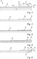
- Figure 1 shows a paper coating arrangement provided with a coating blade 1 having a substrate 2 with a wear-resistant deposit 3 and a masking deposit 4, to be further described in connection with Figures 2-6 .
- the paper coating arrangement has a backing roll 5, rotating in the direction of the arrow, supporting and feeding a fibrous web 6, onto which coating color liquid 7 is provided.
- the coating color liquid 7 is provided in excess amounts.
- the coating blade 1 applies a pressure onto the coating color liquid 7, which causes excess amounts of coating color liquid 7 to be wiped, or doctored, off. The pressure applied by the coating blade 1 determines the amount of coating color fluid 7 that is applied to the fibrous web.
- Figure 2 shows in a side view a masked coating blade 21 having a substrate 22 being provided with a longitudinal wear-resistant deposit 23 and a longitudinal masking deposit 24 adjoining the wear-resistant deposit 23.
- Figure 2 furthermore illustrates schematically the thickness t and the width w of the substrate 22, as referred to herein.
- Figure 2 also illustrates schematically the thickness wrt and width wrw of the wear-resistant deposit 23 and the thickness mt and width mw of the masking deposit 24, as referred to herein.
- Figure 3 shows an alternative arrangement wherein a part of the masking deposit 34 partially overlaps the wear-resistant deposit 33 in order to cover the steep transition from the surface of the wear-resistant deposit 33 to the surface of the substrate 32.
- Figure 4 shows an embodiment wherein the width of the wear-resistant deposit 43 has been reduced and the width of the masking deposit 44 has been extended.
- the masking deposit 44 tapers at a constant rate towards the surface of the substrate 42. The thickness of the masking deposit thus decreases following a straight path.
- the wear-resistant deposit 43 and the masking deposit 44 are shown without the masking deposit 44 overlapping the wear-resistant deposit 43, but the masking deposit may alternatively overlap the wear-resistant deposit.
- Figure 5 shows an embodiment wherein the masking deposit 54 tapers along a curved path towards the surface of the substrate 52.
- the thickness of the masking deposit decreases strongly near the wear-resistant deposit 53 and weakly more remote from the wear-resistant deposit.
- Figure 6 shows an embodiment wherein the substrate 62 has a pre-ground bevel 68.
- the substrate 62 is provided with a wear-resistant deposit 63, extending over the pre-ground bevel 68, and an adjoining masking deposit 64.
- the wear-resistant deposit 63 has a sliding bevel 69.
- Figure 6 also illustrates schematically the width bw of the sliding bevel 69 and the angle ⁇ between the sliding bevel 69 and the surface of the wear-resistant deposit 63, as referred to herein.
- a reference coating blade was manufactured by providing a stainless steel substrate of 100 mm width and 0.457 mm thickness with a Cr 2 O 3 based wear-resistant deposit of 5 mm width.
- a test coating blade according to the invention was manufactured by providing a stainless steel substrate of 100 mm width and 0.457 mm thickness with a Cr 2 O 3 based wear-resistant deposit of 5 mm width and an adjoining polyurethane masking deposit of 15 mm width.
- the masking material was applied as a solvent based dispersion of methyl diphenyl diisocyanate (MDI) based polyurethane.
- MDI methyl diphenyl diisocyanate
- test and reference coating blades were used to top-coat a paper web in a Jagenberg Combiblade coater at the following machine conditions and settings.
- the quality of the "mirror” i.e. the appearance of the wet coated paper surface just after the blade was noticed by the machine operators to be better for the test blade than for the reference blade. After 8 hours of operation, the blades were taken out of operation and washed. There was more build-up of coating color residues at the rear of the wear-resistant deposit on the reference blade than on the test blade. As concerns the test blade, the masking deposit was perfectly clean.
Landscapes
- Paper (AREA)
- Coating Apparatus (AREA)
- Decoration Of Textiles (AREA)
- Treatment Of Fiber Materials (AREA)
- Braiding, Manufacturing Of Bobbin-Net Or Lace, And Manufacturing Of Nets By Knotting (AREA)
Description
- The present invention relates to a coating blade for application of coating color to a fibrous web.
- In the art of coating paper, coating color is applied using a coating blade. Coating blades are known in the art also as doctor blades or scrapers, all of which will be referred to herein as coating blades. The coating blade is typically constituted by a steel substrate onto which a deposit has been applied. For the purpose of coating the paper, an excess of coating color liquid is applied to the surface of the paper and subsequently doctored off using the coating blade. The paper is usually supplied as a web, which is supported and fed by a backing roll during the application and doctoring of coating color. The coating blade applies a pressure on the coating color liquid. Pigment particles in the coating color fluid subject the coating blade to both abrasive and erosive wear.
- It is known in the art to apply a wear-resistant deposit onto the steel substrate in order to extend the life time of coating blades. Worn out coating blades affect the quality of the coated paper in an unacceptable manner and need to be replaced. In case of a blade change the coating machine is either stopped for up to one hour, causing a productivity loss, or still operated during 5-10 minutes, in which period the paper produced needs to be scrapped. Replacement of coating blades are furthermore costly due to the need to "run in" a new coating blade for up to 30 minutes before it can be used to produce coated paper of acceptable quality.
- Wear-resistant deposits are intrinsically hard and/or rigid, thus affecting the flexibility of the coating blade. The tendency in the art is to develop harder and more wear-resistant materials. Moreover, the global amount of applied material tends to increase. This strongly rigidifies the structure, resulting in limited blade flexibility (in the machine direction and in the cross/transversal direction). It is crucial that the coating blade is sufficiently flexible in order to adapt appropriately, at high machine speed, to the topography of the paper to be coated. In order minimize the effect of the deposit on the flexibility of the blade, the wear-resistant deposit normally covers only a relatively narrow area along a longitudinal edge of the substrate.
- It has been found that an abrupt or steep transition at the upstream longitudinal boundary of the wear-resistant deposit, opposite to the longitudinal edge of the coating blade, from the surface of the wear-resistant deposit to the surface of the steel substrate negatively affects the surface quality of the paper coating. It is believed that one reason for this is an impact on the fluid dynamics of the coating color liquid caused by such transition.
-
JP 2006/161713 - Residues of coating color, typically having a high pigment concentration in a surrounding latex phase, tend however to stick to the deposit surface or blade surface upstream of the blade tip. Such residues, or "stickies", cause streaks in the paper coating and thus lead to quality issues.
- For these and other reasons there is a need for development of coating blades for application of coating color to paper.
-
WO 2010/133762 A1 discloses a doctor blade having a multiple layer coating.US 2014/0137361 A1 discloses a cleaning scraper having a coating that is formed with a first coating layer and a second coating layer arranged on the first coating layer.US 2005/0172889 A1 discloses a coating blade having a sacrificial layer covering at least an edge section thereof. - It is an object of the present invention to provide a coating blade for the application of coating color to a fibrous web, allowing for excellent coating quality and outstanding operational productivity. It is thus an object of the present invention to provide a coating blade having an operating zone intended for contact with a coating color, the operating zone being indisposed for affecting negatively the fluid dynamics in the coating color. It is another object of the present invention to provide a coating blade having an operating zone intended for contact with a coating color, the operating zone being indisposed of affecting negatively the flexibility of the coating blade. It is a further object of the present invention to provide such a coating blade having improved surface properties.
- These objects as well as other objects of the invention, which should be apparent to a person skilled in the art after having studied the description below, are accomplished by a coating blade as set out in the appended claims. The masking deposit thus hides a part of the substrate from contact with the coating color. It is contemplated that the masking deposit has a lower elastic modulus than the wear-resistant deposit.
- It was surprisingly found that by providing an operating zone of the coating blade with a wear-resistant deposit adjoined by a masking deposit the high requirements of paper coating can be met in that the coating blade during use has a long life-time, and provides a stable doctoring effect producing coated paper with excellent surface quality. The masking deposit is thus arranged on the substrate next to and joining the wear-resistant deposit. It is contemplated that the masking deposit extends over the substrate, next to the wear-resistant deposit, in a direction perpendicular to the longitudinal edge, for a substantially larger distance than the thickness of the masking deposit, such as for more than about 5 or more than about 10 times its thickness. The masking deposit consists of one or more layers.
- The masking deposit has a lower elastic modulus than the substrate. The substrate typically has an elastic modulus in the range of about 170-220 GPa. In order to not affect negatively the flexibility of the coating blade, the masking deposit typically has an elastic modulus of less than about 50 GPa, preferably less than about 20 GPa. The wear-resistant deposit typically has a higher elastic modulus than the substrate, such as higher than 220 GPa.
- The masking deposit may comprise a polymer material. The polymer material may be a polyurethane material, typically an ester based, ether based or solvent based polyurethane material. The polymer material may alternatively be a polyepoxide, polysiloxane or acrylic polymer. Additives or fillers may be used to improve the mechanical properties of the masking deposit, without affecting negatively the elastic modulus of the masking deposit and/or the flexibility of the coating blade.
- The masking deposit may taper towards the surface of the substrate. A tapered shape is preferred in order to minimize the amount of material used for the masking deposit. The tapered shape additionally improves the fluid dynamic properties of the coating color. The masking deposit may thus taper from a larger thickness near the wear-resistant deposit to a smaller thickness more remote from the wear-resistant deposit. The larger thickness is typically substantially similar to the thickness of the wear-resistant deposit. The masking deposit may taper at a constant rate from the larger thickness to the smaller thickness. The thickness of the masking deposit will thus decrease following a straight path from the larger thickness to the smaller thickness. Typically, however, the masking deposit will taper at varying rates from the larger thickness to the smaller thickness. As an example, the thickness of the masking deposit may decrease strongly near the wear-resistant deposit and weakly more remote from the wear-resistant deposit. The thickness of the masking deposit may thus decrease following a substantially curved path from the larger thickness to the smaller thickness. The masking deposit may taper over substantially its total width or over a narrow part of its width. The masking deposit typically tapers over about 5-95 % of its width, preferably over about 50-90 % of its width.
- The transition between the surface intended for contact with the coating color of the wear-resistant deposit and the surface intended for contact with the coating color of the masking deposit is substantially flush. The surface intended for contact with the coating color of the wear-resistant deposit thus substantially levels with the surface intended for contact with the coating color of the masking deposit at the transition.
- A part of the masking deposit may overlap the wear-resistant deposit. The wear-resistant deposit may be partially overlapped. A partial overlap may typically be narrow, such as less than about 1 mm, preferably covering essentially a steep or abrupt from the surface of the wear-resistant deposit to the surface of the steel substrate. In some embodiments, it may be advantageous that the overlap is wide, typically due to ease of manufacture. A wide overlap may cover a majority of operating zone. A wide overlap may provide the coating blade with alternative surface properties, may protect the wear-resistant deposit before and during "run-in" of the blade and may facilitate "run-in" of the blade.
- The thickness of the masking deposit may be up to about 200 µm, preferably up to 100 µm. The thickness of the masking deposit may vary over the width of the deposit.
- The width of the masking deposit may be in the range of about 5-30 mm, preferably of about 6-16 mm.
- The wear-resistant deposit may comprise a ceramic material, such as a metal oxide, metal carbide, metal nitride or metal boride. Examples of suitable metal oxides are Cr2O3 and Al2O3. Examples of suitable metal carbides are WC and CrC. Examples of suitable metal nitrides are CrN and TiN. The metal carbides are typically present in a metal matrix, such as in a Ni-based or Co-based matrix. The wear-resistant deposit may comprise a cermet. In the present disclosure, a wear-resistant deposit relates to a deposit having a higher abrasive wear-resistance than steel. Furthermore, a wear-resistant deposit relates to a deposit having a higher erosive wear-resistance than steel.
- The width of the wear-resistant deposit may be in the range of about 1-9 mm, preferably about 3-7 mm, more preferably about 4-6 mm. Alternatively, the width of the wear-resistant deposit is in the range of about 1-2.5 mm, preferably about 1.5-2.5 mm. By reducing the width of the wear-resistant deposit, and replacing part of it with the masking deposit, the flexibility of the coating blade increases (i.e. the rigidity of the coating blade decreases). The flexibility increase positively impacts the blade adaptability, leading to reduced "run in" time, improved process stability and higher quality of the coated paper.
- The wear-resistant deposit may have a thickness of up to about 200 µm, preferably up to about 100 µm, typically where it covers an unbevelled part of the substrate. The thickness may vary over the width of the deposit. The deposit may typically be thicker, such as up to about 500 µm, where it covers a pre-ground bevel of the substrate and/or at the longitudinal edge of the coating blade.
- The coating blade may be provided with the wear-resistant deposit by methods known in the art. The coating blade may be provided with the wear-resistant deposit by thermal spraying, preferably by HVOF (high velocity oxygen fuel) spraying or by APS (atmospheric plasma spraying). The raw material for the thermal spraying may be in the form of powder. The wear-resistant deposit may consist of one or more layers, as is customary in the art.
- The wear-resistant deposit may be provided with at least one bevel. The width of the bevel is typically less than about 2 mm. The bevel may form an angle of about 0-45° with the substrate surface onto which the wear-resistant and masking deposits are arranged. The bevel of the wear-resistant deposit provides adaption of the coating blade to the backing roll. The substrate may have a pre-ground bevel in order for the bevel of the wear-resistant deposit to form when applying the wear-resistant material to the substrate. The bevel of the wear-resistant deposit may alternatively, or additionally, be obtained by grinding of the wear-resistant deposit.
- The coating blade of the present invention may be a coating blade adapted for operation in bent mode (0-15° sliding angle towards the web) or stiff mode (15-45° sliding angle towards the web), as illustrated in
Figs. 4 and 5 , respectively ofGB 2 130 924Fig. 4 has a sliding bevel on the wear-resistant deposit but no pre-ground bevel on the substrate whereas the blade ofFig. 5 has both a sliding bevel on the wear-resistant deposit and a pre-ground bevel on the substrate. - The longitudinal wear-resistant deposit may adjoin the longitudinal edge of the substrate.
- The substrate may be a steel substrate, such as a substrate of a carbon steel, for example spring steel, or of a stainless steel. The steel may be hardened, tempered or treated in other ways known in the art. The substrate may typically have a thickness in the range of about 0.3-0.7 mm. The width of the substrate may typically be in the range of about 70-100 mm. The length of the substrate may be up to about 12 meters.
- The fibrous web may be a paper web. The fibrous web may, during application of coating color, be supported and fed by a backing roll. The fibrous web is contacted with coating color and a coating blade is used to doctor off excess amounts of coating color and ensure a correct metering of coating color.
- The coating blade may have been provided with the masking deposit by methods known in the art, for example by a process similar to the one disclosed in
WO 2000/048746 . The masking deposit is typically provided after the wear-resistant deposit has been provided and may be provided before, during or at the end of further surface finishing, such as grinding and/or polishing, of the coating blade. Accordingly, the masking material is applied in a liquid state to the substrate at the back of the wear-resistant deposit. The masking deposit is thus typically not allowed to extend to the edge of the substrate at the tip of the blade.The viscosity and flow properties of the liquid masking material may contribute to the formation of a masking deposit having a shape that tapers from the surface of the wear-resistant deposit towards the surface of the substrate. Alternatively, a shape desired for the masking deposit may be obtained by grinding after solidification of masking material. The coating blade may alternatively have been provided with the masking deposit by spraying of a liquid masking material onto the substrate. When providing the masking deposit by spraying it is contemplated that part of the masking deposit may overlap the wear-resistant deposit, possibly all the way to the longitudinal edge of the coating blade. - As an example, the substrate of the coating blade may be provided with a wear-resistant deposit having a width of about 3-7 mm, preferably about 4-6 mm, and a masking deposit having a width of about 6-16 mm, preferably about 10-15 mm. Such arrangement gives rise to several advantages, some of which are accounted for herein. By adjoining the wear-resistant deposit with a masking deposit, an abrupt or steep transition, opposite to the edge of the coating blade, from the surface of the wear-resistant deposit to the surface of the steel substrate can be avoided in the vicinity of the blade tip without compromising with the blade flexibility. This leads to improved fluid dynamics of the coating color, leading in turn to an improved coating quality. Such an arrangement also allows for improved surface properties of the blade upstream of the blade tip.
- As another example, the substrate of the coating blade may be provided with a wear-resistant deposit having a width of about 1-2.5 mm, preferably about 1.5-2.5 mm, and a masking deposit having a width of about 5-30 mm, such as 15-20 mm. By reducing the width of the wear-resistant deposit, and replacing part of it with the masking deposit, the flexibility of the coating blade increases (i.e. the rigidity of the coating blade decreases). This may lead to an improved metering effect and thus an improved surface quality of the paper coating, without compromising the wear-resistance of the coated blade or the fluid dynamics of the coating color. Such an arrangement also allows for improved surface properties of the blade upstream of the blade tip.
- The features of the present invention described above may be applicable to invention taken alone or in any combination thereof.
- The invention will be described in the following with reference to the appended drawings.
-
Figure 1 shows diagrammatically in a side view a paper coating arrangement. -
Figures 2-6 show diagrammatical side views of five different embodiments of masked coating blades. -
Figure 1 shows a paper coating arrangement provided with acoating blade 1 having asubstrate 2 with a wear-resistant deposit 3 and a maskingdeposit 4, to be further described in connection withFigures 2-6 . Furthermore, the paper coating arrangement has abacking roll 5, rotating in the direction of the arrow, supporting and feeding afibrous web 6, onto whichcoating color liquid 7 is provided. Thecoating color liquid 7 is provided in excess amounts. Thecoating blade 1 applies a pressure onto thecoating color liquid 7, which causes excess amounts ofcoating color liquid 7 to be wiped, or doctored, off. The pressure applied by thecoating blade 1 determines the amount ofcoating color fluid 7 that is applied to the fibrous web. -
Figure 2 shows in a side view amasked coating blade 21 having asubstrate 22 being provided with a longitudinal wear-resistant deposit 23 and alongitudinal masking deposit 24 adjoining the wear-resistant deposit 23.Figure 2 furthermore illustrates schematically the thickness t and the width w of thesubstrate 22, as referred to herein.Figure 2 also illustrates schematically the thickness wrt and width wrw of the wear-resistant deposit 23 and the thickness mt and width mw of the maskingdeposit 24, as referred to herein. -
Figure 3 shows an alternative arrangement wherein a part of the maskingdeposit 34 partially overlaps the wear-resistant deposit 33 in order to cover the steep transition from the surface of the wear-resistant deposit 33 to the surface of thesubstrate 32. -
Figure 4 shows an embodiment wherein the width of the wear-resistant deposit 43 has been reduced and the width of the maskingdeposit 44 has been extended. The maskingdeposit 44 tapers at a constant rate towards the surface of thesubstrate 42. The thickness of the masking deposit thus decreases following a straight path. The wear-resistant deposit 43 and the maskingdeposit 44 are shown without the maskingdeposit 44 overlapping the wear-resistant deposit 43, but the masking deposit may alternatively overlap the wear-resistant deposit. -
Figure 5 shows an embodiment wherein the masking deposit 54 tapers along a curved path towards the surface of thesubstrate 52. The thickness of the masking deposit decreases strongly near the wear-resistant deposit 53 and weakly more remote from the wear-resistant deposit. -
Figure 6 shows an embodiment wherein thesubstrate 62 has apre-ground bevel 68. Thesubstrate 62 is provided with a wear-resistant deposit 63, extending over thepre-ground bevel 68, and an adjoiningmasking deposit 64. The wear-resistant deposit 63 has a slidingbevel 69.Figure 6 also illustrates schematically the width bw of the slidingbevel 69 and the angle α between the slidingbevel 69 and the surface of the wear-resistant deposit 63, as referred to herein. - A reference coating blade was manufactured by providing a stainless steel substrate of 100 mm width and 0.457 mm thickness with a Cr2O3 based wear-resistant deposit of 5 mm width. A test coating blade according to the invention was manufactured by providing a stainless steel substrate of 100 mm width and 0.457 mm thickness with a Cr2O3 based wear-resistant deposit of 5 mm width and an adjoining polyurethane masking deposit of 15 mm width. The masking material was applied as a solvent based dispersion of methyl diphenyl diisocyanate (MDI) based polyurethane. The wear-resistant deposits had a sliding bevel of 10°.
- The test and reference coating blades, respectively, were used to top-coat a paper web in a Jagenberg Combiblade coater at the following machine conditions and settings.
- Coating station configuration:
- Pre-coat (both paper sides - film press; 5-7 g/m2)
- Middle-coat (top paper side - coating rod; 7-8 g/m2)
- Top-coat (top paper side - bent blade; 9-10 g/m2)
- Machine speed: 800 m/min
- Base paper: 150-180 g/m2, 100 % recycled fibers
- Coating color: CaCO3 85 % + clay 15 % + latex binder (solids content 66-67 %), viscosity 950 cPs
- The quality of the "mirror" (i.e. the appearance of the wet coated paper surface just after the blade) was noticed by the machine operators to be better for the test blade than for the reference blade. After 8 hours of operation, the blades were taken out of operation and washed. There was more build-up of coating color residues at the rear of the wear-resistant deposit on the reference blade than on the test blade. As concerns the test blade, the masking deposit was perfectly clean.
- Visual inspection of the used test blade confirms that the polymeric masking deposit at the back of the ceramic wear-resistant deposit resisted to the friction of the coating color back flow during coating of the paper: no dissolution or change (chemical process), no wear (abrasion/erosion process) or delamination of the masking deposit has been noticed. The behaviour of the test blade has been similar to the reference blade regarding coating quality criteria.
Claims (12)
- A coating blade (1, 21) for application of coating color (7) to a fibrous web (6), the coating blade comprising
an elongate substrate (2, 22, 32, 42, 52, 62) having a longitudinal edge, wherein, within an operating zone, intended for contact with a coating color, of the coating blade, the substrate is provided with:a longitudinal wear-resistant deposit (3, 23, 33, 43, 53, 63) adjacent to the longitudinal edge; anda longitudinal masking deposit (4, 24, 34, 44, 54, 64) arranged on the substrate next to and joining the longitudinal wear-resistant deposit, wherein the masking deposit has a lower elastic modulus than the substrate andwherein the transition between the surface intended for contact with the coating color of the wear-resistant deposit and the surface intended for contact with the coating color of the masking deposit is substantially flush. - A coating blade according to claim 1, wherein the masking deposit has an elastic modulus of less than about 50 GPa, preferably less than about 20 GPa.
- A coating blade according to anyone of the previous claims, wherein the masking deposit comprises a polymer material.
- A coating blade according to claim 3, wherein the polymer material is polyurethane.
- A coating blade according to any of the previous claims, wherein the masking deposit tapers towards the surface of the substrate.
- A coating blade according to any one of the previous claims,
wherein a part of the masking deposit overlaps the wear-resistant deposit. - A coating blade according to any one of the preceding claims, wherein the thickness (mt) of the masking deposit is up to about 200 µm, preferably up to about 100 µm.
- A coating blade according to any one of the previous claims, wherein the width (mw) of the masking deposit is in the range of about 5-30 mm, preferably about 6-16 mm.
- A coating blade according to any one of the previous claims, wherein the wear-resistant deposit comprises a ceramic material, such as a metal oxide, metal carbide, metal nitride or metal boride.
- A coating blade according to any one of the previous claims, wherein the width (wrw) of the wear-resistant deposit is in the range of about 1-9 mm, preferably about 3-7 mm, more preferably about 4-6 mm.
- A coating blade according to any one of claims 1-9, wherein the width (wrw) of the wear-resistant deposit is in the range of about 1-2.5 mm, preferably about 1.5 to 2.5 mm.
- A coating blade according to any one of the preceding claims, wherein the thickness (wrt) of the wear-resistant deposit is up to about 200 µm, preferably up to about 100 µm.
Applications Claiming Priority (2)
| Application Number | Priority Date | Filing Date | Title |
|---|---|---|---|
| EP16163276.5A EP3225736A1 (en) | 2016-03-31 | 2016-03-31 | Masked coating blade |
| PCT/EP2017/057581 WO2017167904A1 (en) | 2016-03-31 | 2017-03-30 | Masked coating blade |
Publications (2)
| Publication Number | Publication Date |
|---|---|
| EP3436636A1 EP3436636A1 (en) | 2019-02-06 |
| EP3436636B1 true EP3436636B1 (en) | 2022-01-05 |
Family
ID=55642375
Family Applications (2)
| Application Number | Title | Priority Date | Filing Date |
|---|---|---|---|
| EP16163276.5A Withdrawn EP3225736A1 (en) | 2016-03-31 | 2016-03-31 | Masked coating blade |
| EP17714237.9A Active EP3436636B1 (en) | 2016-03-31 | 2017-03-30 | Masked coating blade |
Family Applications Before (1)
| Application Number | Title | Priority Date | Filing Date |
|---|---|---|---|
| EP16163276.5A Withdrawn EP3225736A1 (en) | 2016-03-31 | 2016-03-31 | Masked coating blade |
Country Status (8)
| Country | Link |
|---|---|
| US (1) | US11466407B2 (en) |
| EP (2) | EP3225736A1 (en) |
| JP (1) | JP6968815B2 (en) |
| KR (1) | KR102471153B1 (en) |
| CN (1) | CN108884641B (en) |
| BR (1) | BR112018069779B1 (en) |
| ES (1) | ES2909586T3 (en) |
| WO (1) | WO2017167904A1 (en) |
Citations (2)
| Publication number | Priority date | Publication date | Assignee | Title |
|---|---|---|---|---|
| US20050172889A1 (en) * | 2002-07-15 | 2005-08-11 | Gunter Bellmann | Coating blade and method of preparing the same |
| US20140137361A1 (en) * | 2011-07-06 | 2014-05-22 | Voith Patent Gmbh | Dirt-repellent cleaning scraper |
Family Cites Families (30)
| Publication number | Priority date | Publication date | Assignee | Title |
|---|---|---|---|---|
| SE437681B (en) | 1982-10-13 | 1985-03-11 | Inventing Ab | CREATIVE OR RABLE FOR CONTROLLABLE PAIRING AND EXTRAORDINATION OF APPLIANCES ON A CURRENT PAPER COAT |
| JP2583611B2 (en) | 1989-07-31 | 1997-02-19 | ノムラテクノリサーチ株式会社 | Manufacturing method of coating blade |
| JPH0347561U (en) | 1989-09-18 | 1991-05-02 | ||
| JPH06508533A (en) * | 1991-04-05 | 1994-09-29 | ワーナー−ランバート・カンパニー | painting cutting tools |
| SE507926C2 (en) * | 1996-12-19 | 1998-07-27 | Btg Kaelle Inventing Ab | Coating sheet for coating a running track |
| SE513660C2 (en) | 1999-02-18 | 2000-10-16 | Btg Eclepens Sa | Process for making sheets with soft edge coating |
| SE0000215L (en) * | 2000-01-25 | 2001-07-26 | Btg Eclepens Sa | Rakelknive |
| JP2002144478A (en) * | 2000-11-16 | 2002-05-21 | Nippon Steel Corp | Alkali-soluble lubricated surface treated metal product with excellent moldability |
| SE519466C2 (en) | 2000-12-07 | 2003-03-04 | Swedev Ab | Schaber or razor blade with nickel coating including abrasion-resistant particles and method of manufacture |
| SE517846C2 (en) | 2001-02-16 | 2002-07-23 | Btg Eclepens Sa | Self-adjusting blades |
| US20030226579A1 (en) * | 2002-06-06 | 2003-12-11 | Carrier Gordon Eugene | Serrated doctor blades |
| FI113676B (en) * | 2002-10-22 | 2004-05-31 | Pikoblade Oy | Method and plant for producing a wear resistant coating on a coating sheet or equivalent |
| EP1508628A1 (en) * | 2003-08-18 | 2005-02-23 | Siemens Aktiengesellschaft | Part comprising a masking layer and method for coating a part |
| SE526191C2 (en) | 2003-12-19 | 2005-07-26 | Sandvik Ab | Egg-provided tools and methods for making them |
| FR2878843B1 (en) * | 2004-12-02 | 2007-07-20 | Saint Gobain | SUBSTRATE PROTECTED AGAINST ORGANIC POLLUTION |
| JP4648692B2 (en) | 2004-12-08 | 2011-03-09 | 株式会社不二工機 | Switching valve device for compressor |
| US7431801B2 (en) * | 2005-01-27 | 2008-10-07 | The Procter & Gamble Company | Creping blade |
| ES2569496T3 (en) * | 2005-07-01 | 2016-05-11 | BTG Eclépens S.A. | Coated blade, improved |
| SE529662C2 (en) * | 2005-11-28 | 2007-10-16 | Mattsonfoeretagen I Uddevalla | Coating method and apparatus |
| DE102006001336A1 (en) | 2006-01-09 | 2007-07-12 | Martin Bauer | Creping doctor, method of making a creping doctor and using a creping doctor |
| CN100387775C (en) | 2006-04-13 | 2008-05-14 | 山东科技大学 | Wear-resistant paper coating scraper |
| JP2007330830A (en) * | 2006-06-10 | 2007-12-27 | Spectris Co Ltd | Coating blade and method of manufacturing the same |
| JP4827897B2 (en) * | 2008-07-11 | 2011-11-30 | 大王製紙株式会社 | Method for producing coated paper for printing |
| DE102009029699A1 (en) | 2009-09-23 | 2011-03-24 | Voith Patent Gmbh | blade coating |
| DE102009029698A1 (en) | 2009-09-23 | 2011-03-24 | Voith Patent Gmbh | blade coating |
| JP5813314B2 (en) | 2010-06-30 | 2015-11-17 | 株式会社野村鍍金 | Coater blade |
| DE102011115813A1 (en) * | 2011-10-13 | 2013-04-18 | Clouth Sprenger Gmbh | Crepe scraper for scraping paper web i.e. tissue web, from drying cylinder in tissue machine, has two ceramic layers arranged one above other at working edge and comprising wear-resistant, hard and less hard ceramic materials, respectively |
| WO2013133762A1 (en) * | 2012-03-08 | 2013-09-12 | Swedev Ab | Electrolytically puls-plated doctor blade with a multiple layer coating |
| CN202492766U (en) | 2012-03-15 | 2012-10-17 | 刘言 | High-strength abrasion-resistant coating scraper |
| US20170361564A1 (en) * | 2014-12-30 | 2017-12-21 | Kimberly-Clark Worldwide, Inc. | Dampened creping blade |
-
2016
- 2016-03-31 EP EP16163276.5A patent/EP3225736A1/en not_active Withdrawn
-
2017
- 2017-03-30 BR BR112018069779-6A patent/BR112018069779B1/en active IP Right Grant
- 2017-03-30 EP EP17714237.9A patent/EP3436636B1/en active Active
- 2017-03-30 WO PCT/EP2017/057581 patent/WO2017167904A1/en not_active Ceased
- 2017-03-30 CN CN201780020884.9A patent/CN108884641B/en active Active
- 2017-03-30 US US16/088,626 patent/US11466407B2/en active Active
- 2017-03-30 KR KR1020187026634A patent/KR102471153B1/en active Active
- 2017-03-30 JP JP2018551783A patent/JP6968815B2/en active Active
- 2017-03-30 ES ES17714237T patent/ES2909586T3/en active Active
Patent Citations (2)
| Publication number | Priority date | Publication date | Assignee | Title |
|---|---|---|---|---|
| US20050172889A1 (en) * | 2002-07-15 | 2005-08-11 | Gunter Bellmann | Coating blade and method of preparing the same |
| US20140137361A1 (en) * | 2011-07-06 | 2014-05-22 | Voith Patent Gmbh | Dirt-repellent cleaning scraper |
Also Published As
| Publication number | Publication date |
|---|---|
| US11466407B2 (en) | 2022-10-11 |
| JP2019510143A (en) | 2019-04-11 |
| BR112018069779A2 (en) | 2019-02-05 |
| WO2017167904A1 (en) | 2017-10-05 |
| BR112018069779B1 (en) | 2022-07-19 |
| EP3225736A1 (en) | 2017-10-04 |
| EP3436636A1 (en) | 2019-02-06 |
| CN108884641B (en) | 2022-05-03 |
| US20190112765A1 (en) | 2019-04-18 |
| KR102471153B1 (en) | 2022-11-25 |
| CN108884641A (en) | 2018-11-23 |
| KR20180128903A (en) | 2018-12-04 |
| JP6968815B2 (en) | 2021-11-17 |
| ES2909586T3 (en) | 2022-05-09 |
Similar Documents
| Publication | Publication Date | Title |
|---|---|---|
| JP4057138B2 (en) | Paper machine / board paper machine roll or finisher roll, manufacturing method thereof, and coating composition thereof | |
| SE437681B (en) | CREATIVE OR RABLE FOR CONTROLLABLE PAIRING AND EXTRAORDINATION OF APPLIANCES ON A CURRENT PAPER COAT | |
| GB2128551A (en) | Scraper with wear-resistant coating | |
| EP0906472B1 (en) | Creping blade | |
| US9044777B2 (en) | Blade coating | |
| US3703019A (en) | Surface conforming wear resistant doctor blade for rolls | |
| SE437682B (en) | SET AND APPLICATION TO APPLY A NUTS-RESISTANT COATING ON A THIN METALLIC, BAND-SHAPED BEARING MATERIAL | |
| CN102666904A (en) | Spray powder for the cermet coating of doctor blades | |
| US20070158045A1 (en) | Edge-provided tool and method for the manufacture thereof | |
| US11466407B2 (en) | Masked coating blade | |
| AU5966386A (en) | Wear resistant doctor blade | |
| EP1920112B1 (en) | Device and method for coating | |
| FI113677B (en) | Wear-resistant coating sheet or equivalent sheet for treating a paper web | |
| WO2006134209A1 (en) | Method and apparatus for making a wear-resistant coating on a blade for the treatment of a paper web, and blade for the treatment of a paper web | |
| CN102575429B (en) | Self-conditioning roll doctoring means | |
| EP1573126A1 (en) | Method and apparatus for making a wear resistant plating on a coating blade or the like | |
| DE102004048517A1 (en) | Gap between scraper blade and rotating paper-making drum is adjusted by release of fluid between drum and blade-holder block | |
| JPH08168713A (en) | Coater blade | |
| JPH09132894A (en) | Metalling roll provided with crown | |
| KR20060134725A (en) | Metal bars for scraping paper coating liquid coated with abrasion resistant materials |
Legal Events
| Date | Code | Title | Description |
|---|---|---|---|
| STAA | Information on the status of an ep patent application or granted ep patent |
Free format text: STATUS: UNKNOWN |
|
| STAA | Information on the status of an ep patent application or granted ep patent |
Free format text: STATUS: THE INTERNATIONAL PUBLICATION HAS BEEN MADE |
|
| PUAI | Public reference made under article 153(3) epc to a published international application that has entered the european phase |
Free format text: ORIGINAL CODE: 0009012 |
|
| STAA | Information on the status of an ep patent application or granted ep patent |
Free format text: STATUS: REQUEST FOR EXAMINATION WAS MADE |
|
| 17P | Request for examination filed |
Effective date: 20180905 |
|
| AK | Designated contracting states |
Kind code of ref document: A1 Designated state(s): AL AT BE BG CH CY CZ DE DK EE ES FI FR GB GR HR HU IE IS IT LI LT LU LV MC MK MT NL NO PL PT RO RS SE SI SK SM TR |
|
| AX | Request for extension of the european patent |
Extension state: BA ME |
|
| DAV | Request for validation of the european patent (deleted) | ||
| DAX | Request for extension of the european patent (deleted) | ||
| STAA | Information on the status of an ep patent application or granted ep patent |
Free format text: STATUS: EXAMINATION IS IN PROGRESS |
|
| 17Q | First examination report despatched |
Effective date: 20191209 |
|
| GRAP | Despatch of communication of intention to grant a patent |
Free format text: ORIGINAL CODE: EPIDOSNIGR1 |
|
| STAA | Information on the status of an ep patent application or granted ep patent |
Free format text: STATUS: GRANT OF PATENT IS INTENDED |
|
| INTG | Intention to grant announced |
Effective date: 20210729 |
|
| GRAS | Grant fee paid |
Free format text: ORIGINAL CODE: EPIDOSNIGR3 |
|
| GRAA | (expected) grant |
Free format text: ORIGINAL CODE: 0009210 |
|
| STAA | Information on the status of an ep patent application or granted ep patent |
Free format text: STATUS: THE PATENT HAS BEEN GRANTED |
|
| AK | Designated contracting states |
Kind code of ref document: B1 Designated state(s): AL AT BE BG CH CY CZ DE DK EE ES FI FR GB GR HR HU IE IS IT LI LT LU LV MC MK MT NL NO PL PT RO RS SE SI SK SM TR |
|
| REG | Reference to a national code |
Ref country code: GB Ref legal event code: FG4D |
|
| REG | Reference to a national code |
Ref country code: CH Ref legal event code: EP |
|
| REG | Reference to a national code |
Ref country code: AT Ref legal event code: REF Ref document number: 1460713 Country of ref document: AT Kind code of ref document: T Effective date: 20220115 |
|
| REG | Reference to a national code |
Ref country code: DE Ref legal event code: R096 Ref document number: 602017051860 Country of ref document: DE |
|
| REG | Reference to a national code |
Ref country code: IE Ref legal event code: FG4D |
|
| REG | Reference to a national code |
Ref country code: FI Ref legal event code: FGE |
|
| REG | Reference to a national code |
Ref country code: LT Ref legal event code: MG9D |
|
| REG | Reference to a national code |
Ref country code: SE Ref legal event code: TRGR |
|
| REG | Reference to a national code |
Ref country code: ES Ref legal event code: FG2A Ref document number: 2909586 Country of ref document: ES Kind code of ref document: T3 Effective date: 20220509 |
|
| REG | Reference to a national code |
Ref country code: NL Ref legal event code: MP Effective date: 20220105 |
|
| PG25 | Lapsed in a contracting state [announced via postgrant information from national office to epo] |
Ref country code: NL Free format text: LAPSE BECAUSE OF FAILURE TO SUBMIT A TRANSLATION OF THE DESCRIPTION OR TO PAY THE FEE WITHIN THE PRESCRIBED TIME-LIMIT Effective date: 20220105 |
|
| PG25 | Lapsed in a contracting state [announced via postgrant information from national office to epo] |
Ref country code: RS Free format text: LAPSE BECAUSE OF FAILURE TO SUBMIT A TRANSLATION OF THE DESCRIPTION OR TO PAY THE FEE WITHIN THE PRESCRIBED TIME-LIMIT Effective date: 20220105 Ref country code: PT Free format text: LAPSE BECAUSE OF FAILURE TO SUBMIT A TRANSLATION OF THE DESCRIPTION OR TO PAY THE FEE WITHIN THE PRESCRIBED TIME-LIMIT Effective date: 20220505 Ref country code: NO Free format text: LAPSE BECAUSE OF FAILURE TO SUBMIT A TRANSLATION OF THE DESCRIPTION OR TO PAY THE FEE WITHIN THE PRESCRIBED TIME-LIMIT Effective date: 20220405 Ref country code: LT Free format text: LAPSE BECAUSE OF FAILURE TO SUBMIT A TRANSLATION OF THE DESCRIPTION OR TO PAY THE FEE WITHIN THE PRESCRIBED TIME-LIMIT Effective date: 20220105 Ref country code: HR Free format text: LAPSE BECAUSE OF FAILURE TO SUBMIT A TRANSLATION OF THE DESCRIPTION OR TO PAY THE FEE WITHIN THE PRESCRIBED TIME-LIMIT Effective date: 20220105 Ref country code: BG Free format text: LAPSE BECAUSE OF FAILURE TO SUBMIT A TRANSLATION OF THE DESCRIPTION OR TO PAY THE FEE WITHIN THE PRESCRIBED TIME-LIMIT Effective date: 20220405 |
|
| PG25 | Lapsed in a contracting state [announced via postgrant information from national office to epo] |
Ref country code: PL Free format text: LAPSE BECAUSE OF FAILURE TO SUBMIT A TRANSLATION OF THE DESCRIPTION OR TO PAY THE FEE WITHIN THE PRESCRIBED TIME-LIMIT Effective date: 20220105 Ref country code: LV Free format text: LAPSE BECAUSE OF FAILURE TO SUBMIT A TRANSLATION OF THE DESCRIPTION OR TO PAY THE FEE WITHIN THE PRESCRIBED TIME-LIMIT Effective date: 20220105 Ref country code: GR Free format text: LAPSE BECAUSE OF FAILURE TO SUBMIT A TRANSLATION OF THE DESCRIPTION OR TO PAY THE FEE WITHIN THE PRESCRIBED TIME-LIMIT Effective date: 20220406 |
|
| PG25 | Lapsed in a contracting state [announced via postgrant information from national office to epo] |
Ref country code: IS Free format text: LAPSE BECAUSE OF FAILURE TO SUBMIT A TRANSLATION OF THE DESCRIPTION OR TO PAY THE FEE WITHIN THE PRESCRIBED TIME-LIMIT Effective date: 20220505 |
|
| REG | Reference to a national code |
Ref country code: DE Ref legal event code: R097 Ref document number: 602017051860 Country of ref document: DE |
|
| PG25 | Lapsed in a contracting state [announced via postgrant information from national office to epo] |
Ref country code: SM Free format text: LAPSE BECAUSE OF FAILURE TO SUBMIT A TRANSLATION OF THE DESCRIPTION OR TO PAY THE FEE WITHIN THE PRESCRIBED TIME-LIMIT Effective date: 20220105 Ref country code: SK Free format text: LAPSE BECAUSE OF FAILURE TO SUBMIT A TRANSLATION OF THE DESCRIPTION OR TO PAY THE FEE WITHIN THE PRESCRIBED TIME-LIMIT Effective date: 20220105 Ref country code: RO Free format text: LAPSE BECAUSE OF FAILURE TO SUBMIT A TRANSLATION OF THE DESCRIPTION OR TO PAY THE FEE WITHIN THE PRESCRIBED TIME-LIMIT Effective date: 20220105 Ref country code: MC Free format text: LAPSE BECAUSE OF FAILURE TO SUBMIT A TRANSLATION OF THE DESCRIPTION OR TO PAY THE FEE WITHIN THE PRESCRIBED TIME-LIMIT Effective date: 20220105 Ref country code: EE Free format text: LAPSE BECAUSE OF FAILURE TO SUBMIT A TRANSLATION OF THE DESCRIPTION OR TO PAY THE FEE WITHIN THE PRESCRIBED TIME-LIMIT Effective date: 20220105 Ref country code: DK Free format text: LAPSE BECAUSE OF FAILURE TO SUBMIT A TRANSLATION OF THE DESCRIPTION OR TO PAY THE FEE WITHIN THE PRESCRIBED TIME-LIMIT Effective date: 20220105 Ref country code: CZ Free format text: LAPSE BECAUSE OF FAILURE TO SUBMIT A TRANSLATION OF THE DESCRIPTION OR TO PAY THE FEE WITHIN THE PRESCRIBED TIME-LIMIT Effective date: 20220105 |
|
| PLBE | No opposition filed within time limit |
Free format text: ORIGINAL CODE: 0009261 |
|
| STAA | Information on the status of an ep patent application or granted ep patent |
Free format text: STATUS: NO OPPOSITION FILED WITHIN TIME LIMIT |
|
| PG25 | Lapsed in a contracting state [announced via postgrant information from national office to epo] |
Ref country code: AL Free format text: LAPSE BECAUSE OF FAILURE TO SUBMIT A TRANSLATION OF THE DESCRIPTION OR TO PAY THE FEE WITHIN THE PRESCRIBED TIME-LIMIT Effective date: 20220105 |
|
| 26N | No opposition filed |
Effective date: 20221006 |
|
| PG25 | Lapsed in a contracting state [announced via postgrant information from national office to epo] |
Ref country code: LU Free format text: LAPSE BECAUSE OF NON-PAYMENT OF DUE FEES Effective date: 20220330 Ref country code: IE Free format text: LAPSE BECAUSE OF NON-PAYMENT OF DUE FEES Effective date: 20220330 |
|
| PG25 | Lapsed in a contracting state [announced via postgrant information from national office to epo] |
Ref country code: SI Free format text: LAPSE BECAUSE OF FAILURE TO SUBMIT A TRANSLATION OF THE DESCRIPTION OR TO PAY THE FEE WITHIN THE PRESCRIBED TIME-LIMIT Effective date: 20220105 |
|
| REG | Reference to a national code |
Ref country code: AT Ref legal event code: UEP Ref document number: 1460713 Country of ref document: AT Kind code of ref document: T Effective date: 20220105 |
|
| PG25 | Lapsed in a contracting state [announced via postgrant information from national office to epo] |
Ref country code: HU Free format text: LAPSE BECAUSE OF FAILURE TO SUBMIT A TRANSLATION OF THE DESCRIPTION OR TO PAY THE FEE WITHIN THE PRESCRIBED TIME-LIMIT; INVALID AB INITIO Effective date: 20170330 |
|
| PG25 | Lapsed in a contracting state [announced via postgrant information from national office to epo] |
Ref country code: MK Free format text: LAPSE BECAUSE OF FAILURE TO SUBMIT A TRANSLATION OF THE DESCRIPTION OR TO PAY THE FEE WITHIN THE PRESCRIBED TIME-LIMIT Effective date: 20220105 Ref country code: CY Free format text: LAPSE BECAUSE OF FAILURE TO SUBMIT A TRANSLATION OF THE DESCRIPTION OR TO PAY THE FEE WITHIN THE PRESCRIBED TIME-LIMIT Effective date: 20220105 |
|
| PG25 | Lapsed in a contracting state [announced via postgrant information from national office to epo] |
Ref country code: MT Free format text: LAPSE BECAUSE OF FAILURE TO SUBMIT A TRANSLATION OF THE DESCRIPTION OR TO PAY THE FEE WITHIN THE PRESCRIBED TIME-LIMIT Effective date: 20220105 |
|
| PGFP | Annual fee paid to national office [announced via postgrant information from national office to epo] |
Ref country code: ES Payment date: 20250429 Year of fee payment: 9 |
|
| PGFP | Annual fee paid to national office [announced via postgrant information from national office to epo] |
Ref country code: CH Payment date: 20250401 Year of fee payment: 9 |
|
| PG25 | Lapsed in a contracting state [announced via postgrant information from national office to epo] |
Ref country code: TR Free format text: LAPSE BECAUSE OF FAILURE TO SUBMIT A TRANSLATION OF THE DESCRIPTION OR TO PAY THE FEE WITHIN THE PRESCRIBED TIME-LIMIT Effective date: 20220105 |
|
| REG | Reference to a national code |
Ref country code: CH Ref legal event code: U11 Free format text: ST27 STATUS EVENT CODE: U-0-0-U10-U11 (AS PROVIDED BY THE NATIONAL OFFICE) Effective date: 20260401 |
|
| PGFP | Annual fee paid to national office [announced via postgrant information from national office to epo] |
Ref country code: SE Payment date: 20260319 Year of fee payment: 10 |
|
| PGFP | Annual fee paid to national office [announced via postgrant information from national office to epo] |
Ref country code: GB Payment date: 20260324 Year of fee payment: 10 |
|
| PGFP | Annual fee paid to national office [announced via postgrant information from national office to epo] |
Ref country code: DE Payment date: 20260319 Year of fee payment: 10 |
|
| PGFP | Annual fee paid to national office [announced via postgrant information from national office to epo] |
Ref country code: AT Payment date: 20260320 Year of fee payment: 10 |
|
| PGFP | Annual fee paid to national office [announced via postgrant information from national office to epo] |
Ref country code: FI Payment date: 20260323 Year of fee payment: 10 Ref country code: BE Payment date: 20260319 Year of fee payment: 10 Ref country code: IT Payment date: 20260324 Year of fee payment: 10 |
|
| PGFP | Annual fee paid to national office [announced via postgrant information from national office to epo] |
Ref country code: FR Payment date: 20260320 Year of fee payment: 10 |