EP3436351B1 - Amenity monument for aircraft cabins - Google Patents
Amenity monument for aircraft cabins Download PDFInfo
- Publication number
- EP3436351B1 EP3436351B1 EP17776889.2A EP17776889A EP3436351B1 EP 3436351 B1 EP3436351 B1 EP 3436351B1 EP 17776889 A EP17776889 A EP 17776889A EP 3436351 B1 EP3436351 B1 EP 3436351B1
- Authority
- EP
- European Patent Office
- Prior art keywords
- monument
- amenity
- passenger
- panels
- privacy
- Prior art date
- Legal status (The legal status is an assumption and is not a legal conclusion. Google has not performed a legal analysis and makes no representation as to the accuracy of the status listed.)
- Active
Links
- 238000005192 partition Methods 0.000 claims description 23
- 230000002452 interceptive effect Effects 0.000 claims description 13
- 238000009434 installation Methods 0.000 claims description 2
- 239000011521 glass Substances 0.000 description 14
- 238000010586 diagram Methods 0.000 description 12
- 230000004888 barrier function Effects 0.000 description 10
- 230000007246 mechanism Effects 0.000 description 8
- 230000000694 effects Effects 0.000 description 6
- 230000033001 locomotion Effects 0.000 description 5
- 230000008859 change Effects 0.000 description 4
- 239000000463 material Substances 0.000 description 4
- 230000005540 biological transmission Effects 0.000 description 3
- 238000010276 construction Methods 0.000 description 3
- 230000003287 optical effect Effects 0.000 description 3
- 238000009413 insulation Methods 0.000 description 2
- 238000000638 solvent extraction Methods 0.000 description 2
- 241001503987 Clematis vitalba Species 0.000 description 1
- 238000013459 approach Methods 0.000 description 1
- 235000019568 aromas Nutrition 0.000 description 1
- 238000000222 aromatherapy Methods 0.000 description 1
- 230000003190 augmentative effect Effects 0.000 description 1
- 235000013361 beverage Nutrition 0.000 description 1
- 230000017531 blood circulation Effects 0.000 description 1
- 230000000295 complement effect Effects 0.000 description 1
- 230000001419 dependent effect Effects 0.000 description 1
- 239000000835 fiber Substances 0.000 description 1
- 230000010006 flight Effects 0.000 description 1
- 230000036541 health Effects 0.000 description 1
- 230000003993 interaction Effects 0.000 description 1
- 230000002045 lasting effect Effects 0.000 description 1
- 230000001795 light effect Effects 0.000 description 1
- 210000003141 lower extremity Anatomy 0.000 description 1
- 235000012054 meals Nutrition 0.000 description 1
- 238000000034 method Methods 0.000 description 1
- 230000004048 modification Effects 0.000 description 1
- 238000012986 modification Methods 0.000 description 1
- 239000002304 perfume Substances 0.000 description 1
- 238000001126 phototherapy Methods 0.000 description 1
- 230000005855 radiation Effects 0.000 description 1
- 230000004044 response Effects 0.000 description 1
- 238000011012 sanitization Methods 0.000 description 1
- 238000004088 simulation Methods 0.000 description 1
- 239000011343 solid material Substances 0.000 description 1
Images


Classifications
-
- B—PERFORMING OPERATIONS; TRANSPORTING
- B64—AIRCRAFT; AVIATION; COSMONAUTICS
- B64D—EQUIPMENT FOR FITTING IN OR TO AIRCRAFT; FLIGHT SUITS; PARACHUTES; ARRANGEMENT OR MOUNTING OF POWER PLANTS OR PROPULSION TRANSMISSIONS IN AIRCRAFT
- B64D11/00—Passenger or crew accommodation; Flight-deck installations not otherwise provided for
- B64D11/06—Arrangements of seats, or adaptations or details specially adapted for aircraft seats
- B64D11/0601—Arrangement of seats for non-standard seating layouts, e.g. seats staggered horizontally or vertically, arranged in an angled or fishbone layout, or facing in other directions than the direction of flight
-
- B—PERFORMING OPERATIONS; TRANSPORTING
- B64—AIRCRAFT; AVIATION; COSMONAUTICS
- B64D—EQUIPMENT FOR FITTING IN OR TO AIRCRAFT; FLIGHT SUITS; PARACHUTES; ARRANGEMENT OR MOUNTING OF POWER PLANTS OR PROPULSION TRANSMISSIONS IN AIRCRAFT
- B64D11/00—Passenger or crew accommodation; Flight-deck installations not otherwise provided for
- B64D11/06—Arrangements of seats, or adaptations or details specially adapted for aircraft seats
- B64D11/0602—Seat modules, i.e. seat systems including furniture separate from the seat itself
-
- B—PERFORMING OPERATIONS; TRANSPORTING
- B64—AIRCRAFT; AVIATION; COSMONAUTICS
- B64D—EQUIPMENT FOR FITTING IN OR TO AIRCRAFT; FLIGHT SUITS; PARACHUTES; ARRANGEMENT OR MOUNTING OF POWER PLANTS OR PROPULSION TRANSMISSIONS IN AIRCRAFT
- B64D11/00—Passenger or crew accommodation; Flight-deck installations not otherwise provided for
- B64D11/0015—Arrangements for entertainment or communications, e.g. radio, television
-
- B—PERFORMING OPERATIONS; TRANSPORTING
- B64—AIRCRAFT; AVIATION; COSMONAUTICS
- B64D—EQUIPMENT FOR FITTING IN OR TO AIRCRAFT; FLIGHT SUITS; PARACHUTES; ARRANGEMENT OR MOUNTING OF POWER PLANTS OR PROPULSION TRANSMISSIONS IN AIRCRAFT
- B64D11/00—Passenger or crew accommodation; Flight-deck installations not otherwise provided for
- B64D11/0023—Movable or removable cabin dividers, e.g. for class separation
-
- B—PERFORMING OPERATIONS; TRANSPORTING
- B64—AIRCRAFT; AVIATION; COSMONAUTICS
- B64D—EQUIPMENT FOR FITTING IN OR TO AIRCRAFT; FLIGHT SUITS; PARACHUTES; ARRANGEMENT OR MOUNTING OF POWER PLANTS OR PROPULSION TRANSMISSIONS IN AIRCRAFT
- B64D11/00—Passenger or crew accommodation; Flight-deck installations not otherwise provided for
- B64D11/06—Arrangements of seats, or adaptations or details specially adapted for aircraft seats
- B64D11/0602—Seat modules, i.e. seat systems including furniture separate from the seat itself
- B64D11/0605—Seat modules, i.e. seat systems including furniture separate from the seat itself including tables or desks
-
- B—PERFORMING OPERATIONS; TRANSPORTING
- B64—AIRCRAFT; AVIATION; COSMONAUTICS
- B64D—EQUIPMENT FOR FITTING IN OR TO AIRCRAFT; FLIGHT SUITS; PARACHUTES; ARRANGEMENT OR MOUNTING OF POWER PLANTS OR PROPULSION TRANSMISSIONS IN AIRCRAFT
- B64D11/00—Passenger or crew accommodation; Flight-deck installations not otherwise provided for
- B64D11/06—Arrangements of seats, or adaptations or details specially adapted for aircraft seats
- B64D11/0611—Arrangements of seats, or adaptations or details specially adapted for aircraft seats with means for holding the passenger in a standing position
-
- B—PERFORMING OPERATIONS; TRANSPORTING
- B64—AIRCRAFT; AVIATION; COSMONAUTICS
- B64D—EQUIPMENT FOR FITTING IN OR TO AIRCRAFT; FLIGHT SUITS; PARACHUTES; ARRANGEMENT OR MOUNTING OF POWER PLANTS OR PROPULSION TRANSMISSIONS IN AIRCRAFT
- B64D11/00—Passenger or crew accommodation; Flight-deck installations not otherwise provided for
- B64D11/04—Galleys
-
- B—PERFORMING OPERATIONS; TRANSPORTING
- B64—AIRCRAFT; AVIATION; COSMONAUTICS
- B64D—EQUIPMENT FOR FITTING IN OR TO AIRCRAFT; FLIGHT SUITS; PARACHUTES; ARRANGEMENT OR MOUNTING OF POWER PLANTS OR PROPULSION TRANSMISSIONS IN AIRCRAFT
- B64D11/00—Passenger or crew accommodation; Flight-deck installations not otherwise provided for
- B64D2011/0046—Modular or preassembled units for creating cabin interior structures
Definitions
- U. S. Provisional Patent Application Serial No. 62/316,691 is related to an "Airline Onboard Revenue Generating Display Area," .
- U.S. Patent Application Serial No. 15/288,823 to B/E Aerospace, Inc. is related to an "Aircraft Modular Lavatory System,”.
- passengers may be permitted to leave their seat. For example, on a long flight lasting more than 3 hours, lack of physical movement can create unhealthy conditions, such as limited blood flow in the lower extremities. When passengers leave their seats to stretch their legs, they typically have little opportunity to find someplace of interest in the cabin where they are allowed to go. Also, passengers may find clearance difficult due to activities in the aisle such as meal service or beverage service.
- the inventors recognized the need for a location for passengers to temporarily dwell while taking a break from sitting. Additionally, the inventors recognized the need for a location where a passenger may tuck in to avoid collision with a galley cart or other aisle impedance.
- US2011101160 A1 discloses galley units having a moveable galley structure in the interior aircraft cabin.
- the galley structure may be moved so as to be laterally adjacent the main cabin door and thereby provide access to the door.
- the galley structure may be moved laterally so as to cover the main cabin door and thereby provide enhanced acoustic and/or thermal insulation in the main cabin door area.
- the space vacated by the moveable galley structure may thus expose other galley structures and/or equipment.
- US2012025018 A1 discloses a class divider for dividing seating areas of aircraft, which has cavity defined between wall members, where one of members allows seat in class to be contiguous to divider and feet of passenger to be located below seat in class.
- US 2012038587 A1 discloses an aircraft passenger seat privacy partition including a screen selectively switchable between an opaque optical state and a substantially transparent optical state in response to a change in voltage applied to the screen, and a touch-responsive switch embedded in the screen for detecting a change in capacitance in the screen and applying the voltage change to the screen to selectively switch between the opaque and substantially transparent optical states.
- US 2012228902 A1 discloses a seating arrangement for an aircraft.
- the arrangement provides a plurality of seating positions, a seating position comprising a seat and a footwell.
- the footwell of a first seating position is located beside the seat of a second seating position, the second seating position being located generally forward of the first seating position.
- Each seat is operable into a reclined state in which a leg-supporting component of the seat projects into the associated footwell.
- a tray assembly is associated with each console, the tray assembly being deployable from a stowed state in or on the console in which it is disposed generally parallel with a ground surface on which the seating arrangement rests during use.
- US9022320 B2 discloses an aircraft passenger suite including a seat configured for movement between an upright position and a horizontal bed position, an ottoman positioned apart from the passenger seat, and at least one armrest assembly configured for vertical movement, wherein the seat, ottoman and at least one armrest reside in horizontal alignment to form a bed in the horizontal bed position.
- EP 2783983 A1 discloses a passenger module for a seating array for an aircraft cabin which comprises: a pair of end walls generally extending in a first direction connected by at least one side wall generally extending in a second direction which is substantially orthogonal to the first direction, at least one of the walls defining an entrance to the module; at least one door assembly moveable from a stowed position in which the entrance is unobstructed by the door assembly to a deployed position in which the entrance is at least partially obstructed by the door assembly; an ottoman; and a seat assembly orientated in the second direction so as to face the ottoman.
- the ottoman is spaced from the seat in the second direction and the ottoman is wider in the first direction than the seat.
- US 2010219292 A1 discloses an adjustable partitioning mechanism for an aircraft which comprises a more or less straight upper rod of variable length and assumed to be horizontal.
- the rod comprises at its end's connection means allowing the rod to pivot around a vertical axis.
- the mechanism further comprises a curtain having attachment means intended to cooperate with complementary attachment means mounted on the rod.
- the invention also relates to an aircraft equipped with at least one such partitioning mechanism.
- the invention is defined according to claim 1 and preferred embodiments are defined according to the dependent claims 2 to 10.
- Preferred embodiments relate to an amenity monument installed in the middle of a cabin space that absorbs "dead-space" in a seating layout while simultaneously providing features and amenities that are desirable to passengers. In preferred embodiments, this may substantially enhance the array of seating options and configurations available to an aircraft interior designer.
- the amenity monument may be equipped with dimmable panels that are set to a transparent condition during taxi, take-off and landing. During flight, the dimmable panels may set to a translucent or opaque condition that provides privacy for the passenger utilizing the amenity monument as well as passengers seated nearby.
- the monuments may provide enhanced amenities like curved, surround- view screens and which display gaming, advertising, multimedia and/or retail content.
- the amenity monument is defined in part by a partition formed in part by the privacy partitions of one or more adjacent passenger seating suites, where a footwell of at least one passenger seating suite extends into and is encompassed by features of the amenity monument.
- a footwell region of a passenger suite may be hidden behind exterior vertical surfaces of a storage compartment section of the amenity monument.
- the storage compartment for example, may be disposed beneath a horizontal surface (e.g., countertop).
- the amenity monument in one example, may be used for displaying multimedia information to passengers including advertisements and/or the opportunity to purchase retail items. Further to the example, the storage compartment may house merchandise available for purchase. In another example, the amenity monument may be used for displaying destination information such as lodging, activities and sites of interest.
- the storage compartment may house travel brochures or other materials related to travel destinations.
- the amenity monument includes an inset region in an interior of the amenity monument sized to accept an average adult passenger such that a galley cart may transit an aisle abutting the amenity monument.
- the inset region for example, may be bound by the footwell of two opposing passenger suites between which the amenity monument is situated.
- one or more privacy panels may be disposed from an upper edge of adjoining partitions of the passenger suite(s) to at least an eye level of an average passenger.
- the one or more privacy panels in some implementations comprise transparent, dimmable material.
- at least one of the one or more privacy panels comprises at least a portion of a display monitor configured to present visitors to the amenity monument with information.
- the terms “approximately,” “about,” “proximate,” “minor variation,” and similar terms generally refer to ranges that include the identified value within a margin of 20%, 10% or preferably 5% in certain embodiments, and any values therebetween.
- FIG. 1 depicts a schematic diagram representing a passenger usage of an easily accessible display space on an airplane installed with an exemplary airline display compartment, which does not represent the claimed invention, but which may be useful for understanding it.
- a passenger 100 approaches an amenity monument 105 from an aisle 110.
- the amenity monument 105 is installed adjacent to the aisle 110 with at least three partitions 115a-H5c extending from the floor 120 towards a ceiling.
- the three partitions create a partial enclosure and do not reach a ceiling in this depiction.
- a planar surface 125 extends parallel to the floor 120 from a partition 115b towards the aisle 110.
- the planar surface 125 supports various displays 130 with examples of physical items 135.
- the storage compartments 140 may store inventory of the physical items 135 or any other item displayed in the display 130.
- a footwell of an aft-adjacent and/or a forward-adjacent suite may protrude into the space under the planar surface 125.
- the amenity monument 105 can be installed on an airplane to advantageously use non- revenue-generating space to produce revenue for an airline and various airline partners. Furthermore, the construction of amenity monument 105 allows a passenger 100 to access the amenity monument 105 easily from the aisle 110 and allows the passenger 100 to view physical items 135 in partial privacy.
- the partitions 115a-l 15c may extend from a floor 120 all the way to a ceiling or may only extend part of the way to a ceiling. The height of the partitions 115a- 115c may offer some or very little privacy for a passenger 100 to view and browse the items for purchase 135.
- the installation of the amenity monument 105 may, in some examples, advantageously encourage passengers to walk about the cabin during flight, and may advantageously create additional value for passengers, and potential revenue-generating opportunities for the airline.
- the various displays 130 on the planar surface 125 may be virtual or physical.
- the display may be a projection or may be on a screen capable of interaction.
- the inventory in the storage compartments 140 are physical items.
- the storage compartments 140 have doors that swing or slide open, but the doors may alternately slidably retract and protrude towards the aisle 110.
- the storage compartments 140 may be installed with a locking mechanism.
- the locks may be integrated with a payment mechanism to engage or disengage when payment is made so that the physical items 135 may be dispensed to the passenger 100.
- the locks may be manually accessed by a flight attendant or other airline professional to dispense the physical items 135 purchased by the passenger 100.
- the locks may automatically engage or disengage with an integrated payment system to dispense the physical items 135 to the passenger 100.
- a payment mechanism may be installed as a device in the amenity monument 105.
- a payment mechanism may also be operated by a flight attendant or other airline professional through a mobile terminal.
- the payment mechanism in some examples, may be provided through readily available software installed on personal passenger devices or provided airline devices.
- the physical items 135, in some examples, may be luxury goods.
- luxury goods can include jewelry, watches, or other physical items 135.
- the luxury goods may, in some embodiments, be perfumes or luxury gift items.
- the luxury goods may be similar to physical items available in a Duty-Free airport shop at a destination and available for pick up upon arrival.
- the physical items 135 would be available to the passenger 100 to enhance their inflight experience, to provide entertainment, and to encourage movement during a flight.
- the amenity monument 105 may advantageously promote happier customers and additional revenue streams.
- FIG. 2 depicts a schematic diagram of an airplane cabin layout installed with various exemplary airline display or amenity monuments.
- an exemplary layout of an airplane 200 is provided including various seating units 205a-205t, aisles 210a-210b, and various amenity monuments 215a-215c.
- the aisles 210a-210b extend between a front 220 of the airplane 200 towards a back 225 of the airplane 200.
- the compartments 215a-215c are easily accessible from the aisles 210a-210b and interspersed around the aircraft cabin 200.
- the compartments 215a-215c are advantageously placed around the aircraft to be accessible to passengers from various seating compartments 205a-205t. The passengers, during flight, may walk around their section of the aircraft and interact with the display or amenity monuments providing movement opportunities and entertainment.
- FIG. 3 depicts a schematic diagram representing a passenger usage of an exemplary configuration of an airline display compartment.
- an airplane passenger 300 engages with a display compartment 305.
- the display compartment 305 is installed adjacent to an aisle 310, which extends between a front of a plane and a back of a plane, and constructed of various partitions 315a-315c which extend from a floor 320 towards a ceiling and various planar surfaces 325 parallel to a cabin floor 320.
- the partitions 315a-315c may only extend partially towards a ceiling.
- the planar surfaces 325 are constructed such that the passenger 300 can engage with the display compartment 305 from the aisle 310 or by stepping into an inner display compartment 330.
- the inner display compartment 330 is defined by an inner surface 335 of the planar surfaces 325.
- the planar surface 325 is constructed to support various displays 340.
- the display compartment 305 is advantageously constructed to allow a passenger 300 to engage with various displays 340 while keeping the aisle 310 clear.
- the display compartment 305 additionally allows an under-commercialized space on an airplane to be converted into a revenue-generating space, while maintaining regular operations on the plane.
- the display compartment 305 allows a passenger 300 to engage with various displays 340 while on an airplane.
- the various displays 340 may be virtual or physical.
- Virtual displays for example, may be projections or may be viewable on interactive screens.
- the virtual displays may allow a passenger 300 to preview attractions at the destination or at other destinations for future trips.
- the attractions may be previews of museums, points of interest, activities of interest, flight connection, luggage pickup, or terminal amenities, or local businesses at the passenger's destination (e.g., hotels, airport terminal kiosk information, transportation options).
- the businesses previewed, for example, may be popular restaurants or stores.
- the activities of interest previewed, for example, may be installed by tour guide companies, museums, or theaters.
- the physical displays may be similar to the physical goods displays depicted in FIG. 1 .
- the physical displays may be replicas of museums, points of interest, or of other possible destinations.
- the physical displays may be informational, to allow the passenger 300 to better navigate the destination airport, or the destination city.
- the display compartment 305 may advantageously allow for passenger education and a premium passenger experience.
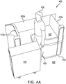
- FIG. 4A and 4B depict a schematic and plan diagram representing a passenger using an exemplary configuration of an airline amenity monument designed, in some examples, for display, merchandising, or entertainment purposes.
- a passenger 400 engages with an amenity monument 405.
- the amenity monument 405 is constructed with various partitions 410a-410c which extend from a floor 415 towards a ceiling and various planar surfaces 420 which extend from the partitions 410a-410c parallel to the floor 415.
- the various planar surfaces 420 extend from the partitions 410a-410c to an inner amenity monument 425.
- the inner amenity monument 425 can be entered from an aisle 430 which, for example, may extend between the front of an aircraft cabin to the back of the aircraft cabin.
- the passenger 400 entered the inner amenity monument 425 to allow a service cart 435 to travel towards the front or the back of the cabin by way of the aisle 430.
- a perspective drawing shows the passenger 400 engaging with the amenity monument 405 while allowing the cart 435 to pass down the aisle 430.
- the amenity monument 405 is advantageously constructed so as not to disrupt travel of the cart 435 or of any people using the aisle 430.
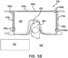
- FIG. 5A and 5B depict a schematic and plan diagram representing a passenger using an exemplary configuration of an airline display compartment with see-through electrically dimmable glass.
- a passenger 400 engages with an amenity monument 505 (similar in construction to the amenity monument 405 of figure 4A ).
- figure 5A includes the additional features of three electrically dimmable glass panels 540a, 540b, and 540c. These panels may be set to a transparent condition during taxi, take-off and landing and to an opaque condition during other times to preserve the privacy of passengers seated in suites near the amenity monument.
- the electrically dimmable glass panels 540a-540c are shown as being supported by the partitions 410a-410c, respectively.
- the electrically dimmable glass panels 540a-540c each possess an electrochromic layer that is configured to adjust an amount of transparency of the electrochromic layer based on an applied voltage.
- the electrically dimmable glass panels 540a-540c aid in improving the amount of privacy provided to suites adjoining the amenity monument 505.
- the electrochromic layer can change light transmission properties to exhibit varied amounts of transparency, translucency, or opacity based on the applied voltage.
- the amount of voltage supplied to the electrochromic layer of each of the electrically dimmable glass panels 540a-540c may be individually controlled by a controller that determines the light transmission properties of the electrochromic layer based on predetermined settings, or inputs received from a passenger or flight attendant at an input/output (I/O) device such as a touchscreen video monitor at a passenger suite or flight attendant station.
- I/O input/output
- a passenger seated in a passenger suite may select a transparent setting for the electrochromic layer at one of the I/O devices 545a-545c when the passenger desires to increase the amount of light transmission between the passenger suite and the amenity monument 505.
- the passenger may select a setting at one of the I/O devices 545a-545c to adjust the electrochromic layer to exhibit varied amounts of translucency or opacity.
- a passenger with an electrically dimmable glass panel separating a passenger suite from the amenity monument 505 may cause the electrically dimmable glass panel to become opaque to provide privacy from persons using the amenity monument 505.
- the embodiment of FIG. 5 A is enhanced with interactive displays on countertop 420.
- multiple flat screens may be provided to substantially surround the passenger with 400 with multimedia content.
- one screen may be positioned in front of the passenger, one to the right of the passenger, and one to the left of the passenger.
- the displays may optionally be equipped with touch-screens and/or keyboards.
- the displays may extend the "desktop" of a single computer or may be independent displays optionally driven by separate processors.
- the display screens are preferably titled upward to accommodate the viewing angle of passenger 400.
- the multiple displays may be replaced with curved display that occupies substantially the entire span of the countertop 420.
- This embodiment may provide an enhanced, immersive experience for the passenger 400. Coupled with the privacy provided by the dimmable panels, the passenger 400 may have an enhanced sense of intimacy and privacy that encourages the passenger to interact with the displays.
- Further privacy may be provided by dimmable panels which extend along the aisle toward the passenger from panels 540a and 540c. Such may provide almost complete privacy to the passenger 400 and may substantially enhance the likelihood that the passenger will utilize the amenities offered in monument 405.
- the amenities may include video games and other multimedia content such as news and information concerning points of interests at the aircraft destinations.
- the passenger opening or cavity formed by the curved countertop 420 may be widened to accommodate two passengers. Headsets and handheld controls may be provided for at least two passengers.
- the passengers may be spouses and they may view on the screen(s) information related to a scuba-diving excursion and the passengers may book the excursion during the flight.
- the passengers are friends or siblings and they may, for a fee, play two-player video games during the flight.
- FIG. 5B a perspective drawing shows the passenger 400 engaging with the amenity monument 505 while allowing the cart 435 to pass down the aisle 430.
- Passengers seated on a side of the electrically dimmable glass panels 540a-540c opposite the amenity monument 505 may desire (or may be indifferent to) increased privacy from the passenger 400 engaging with the amenity monument.
- the privacy desires of such a seated passenger may be accommodated by adjustably controlling the transparency (or opacity) of one (or more than one) of the electrically dimmable glass panels 540a-540c.
- FIG. 6A and 6B depict a schematic and plan diagram representing a passenger using an exemplary configuration of an airline display compartment with touch screen monitors.
- a passenger 400 engages with an amenity monument 605 (similar in construction to the amenity monument 405 and 505 of figures 4A and 5A , respectively).
- figure 6A has a different feature of three touch screen monitors 640a, 640b, and 640c.
- the touch screen monitors 640a-640c are shown as being supported by the partitions 410a-410c, respectively.
- the touch screen monitors 640a-640c may be used for a variety of commercial uses.
- the touch screen monitors 640a-640c may provide information about the tourist areas and locale based interests the aircraft is flying towards.
- the touch screen monitors 640a-640c may be used to display various types of merchandise, such as jewelry or accessories (such as rings or watches), available to passengers through the in-flight magazine or duty free offerings.
- the touch screen monitors 640a-640c may be used to render images of artefacts of museums or art galleries, thus providing a means to inform the premium passengers on long range flights about possible places of interest they may wish to visit upon landing at their destination.
- several watches, artefacts, and electronic devices are displayed on the touch screen monitors 640b.
- a perspective drawing shows the passenger 400 engaging with the amenity monument 605 while allowing the cart 435 to pass down the aisle 430.
- the passenger 400 may interact with any of the touch screen monitors 640a-640c while they are using the amenity monument 605.
- the touch screen monitors 640a-640c may also be configured to provide purchase options for passengers, such that a passenger can select an item they want to purchase on one of the touch screen monitors 640a-640c, and then pay for the item at the amenity monument 605 (or perhaps add the item to their virtual "cart" and purchase at a later time).
- an airline display compartment may incorporate a see-through electrically dimmable glass panel.
- see-through electrically dimmable glass panels are described in further detail with reference to, for example, at least the various Figures of U. S. Patent Application Serial No. 62/317,701 , entitled “Dimmable Window for Direct View in Aircraft Cabins,” by Shawn Claflin, filed on April 4, 2016.
- an amenity monument may be separated from an aisle by a retractable barrier.
- the retractable barrier may be constructed of a flexible material with a fastening end extending from a retraction device towards a fastening device.
- the retractable barrier may limit the number of participants able to engage at one time. Furthermore, the retractable barrier may increase safety, security, or privacy for those engaging with the amenity monument.
- a barrier may extend from the floor of an amenity monument and may define an entrance to the amenity monument.
- the barrier may be constructed of a solid material.
- the barrier may be constructed of a flexible material.
- the barrier may slidably extend across the entrance.
- the barrier may hingedly connect to one side of the entrance to pivotally open or close.
- the barrier may limit the number of participants able to engage with the amenity monument at one time.
- the amenity monument may include a gaming room for engaging in video gaming with fellow passengers.
- the amenity monument may include a dispensing apparatus, which houses items for purchase and has a display or interactive component allowing a person to purchase items being housed within the dispensing apparatus.
- the dispensing apparatus may be a vending machine.
- an amenity monument may include an interactive system.
- the interactive system may include various accessories.
- the accessories may be headphones or an augmented/virtual reality headset.
- the accessories may include interactive displays, which may be touchscreen or voice enabled.
- the interactive displays may provide relevant information about a destination.
- the interactive display may be used to purchase items or content, and may have various connection capabilities to attach a personal device.
- the amenity monument may accommodate various payment devices.
- storage compartments may be incorporated into the amenity monument.
- an airline display compartment may include a workstation.
- an amenity monument may have a sanitizing device.
- an amenity monument may include a charging station 1550.
- an activity compartment may include an exercise machine.
- the exercise machine may be a stationary bicycle or a stair climber.
- the exercise machine may be configured to be compact or contained in a small space.
- an activity compartment may have emitting devices to emit light for the purposes of light therapy.
- the emitting devices emit radiation for the purposes of tanning.
- the emitting devices emit mists with or without aromas for the purposes of relaxation, health and wellness, or aromatherapy.
- the amenity monument may include an interactive floor.
- the interactive floor may be used in simulations or games. For example, dance or active games may be enhanced by using floor sensors.
- the interactive floor may have pressure sensors or may have fiber optic capabilities to allow for various light effects.
Landscapes
- Engineering & Computer Science (AREA)
- Aviation & Aerospace Engineering (AREA)
- Electrochromic Elements, Electrophoresis, Or Variable Reflection Or Absorption Elements (AREA)
- User Interface Of Digital Computer (AREA)
- Controls And Circuits For Display Device (AREA)
Description
-
U. S. Provisional Patent Application Serial No. 62/316,691 U.S. Patent Application Serial No. 15/288,823 to B/E Aerospace, Inc., is related to an "Aircraft Modular Lavatory System,". - During some portions of a flight, passengers may be permitted to leave their seat. For example, on a long flight lasting more than 3 hours, lack of physical movement can create unhealthy conditions, such as limited blood flow in the lower extremities. When passengers leave their seats to stretch their legs, they typically have little opportunity to find someplace of interest in the cabin where they are allowed to go. Also, passengers may find clearance difficult due to activities in the aisle such as meal service or beverage service.
- The inventors recognized the need for a location for passengers to temporarily dwell while taking a break from sitting. Additionally, the inventors recognized the need for a location where a passenger may tuck in to avoid collision with a galley cart or other aisle impedance.
- The inventors also recognized that this need could be satisfied by utilizing "dead space" that occurs in certain aircraft seating layouts. For example, business class suite layouts in certain aircraft sometimes leave areas of the cabin floor unused. Heretofore such layouts were generally avoided or the suites were rearranged such that the unused spaced is positioned adjacent a bulkhead or other monument such that an additional monument such as a storage cabinet may be conveniently positioned in the gap. Such storage cabinets generally cannot be positioned in the middle of a cabin, including because safety guidelines require flight attendants to have line of sight across the cabin during take-off and landing. Seating layouts have substantially limited by the constraint that "dead space" in the middle of a cabin must generally be avoided. By eliminating this constraint, the inventors have substantially broadened the scope of available seating layouts.
-
US2011101160 A1 discloses galley units having a moveable galley structure in the interior aircraft cabin. During passenger ingress/egress and during certain phases of the aircraft's flight (e.g., take-off and landing), the galley structure may be moved so as to be laterally adjacent the main cabin door and thereby provide access to the door. During other phases of the aircraft's flight (e.g., during cruise flight at altitude), the galley structure may be moved laterally so as to cover the main cabin door and thereby provide enhanced acoustic and/or thermal insulation in the main cabin door area. The space vacated by the moveable galley structure may thus expose other galley structures and/or equipment. An aircraft which includes such an aircraft galley unit and methods to achieve acoustic and/or thermal insulation for an aircraft cabin door using such an aircraft galley unit are also provided.US2012025018 A1 discloses a class divider for dividing seating areas of aircraft, which has cavity defined between wall members, where one of members allows seat in class to be contiguous to divider and feet of passenger to be located below seat in class.US 2012038587 A1 discloses an aircraft passenger seat privacy partition including a screen selectively switchable between an opaque optical state and a substantially transparent optical state in response to a change in voltage applied to the screen, and a touch-responsive switch embedded in the screen for detecting a change in capacitance in the screen and applying the voltage change to the screen to selectively switch between the opaque and substantially transparent optical states.US 2012228902 A1 discloses a seating arrangement for an aircraft. The arrangement provides a plurality of seating positions, a seating position comprising a seat and a footwell. The footwell of a first seating position is located beside the seat of a second seating position, the second seating position being located generally forward of the first seating position. Each seat is operable into a reclined state in which a leg-supporting component of the seat projects into the associated footwell. A tray assembly is associated with each console, the tray assembly being deployable from a stowed state in or on the console in which it is disposed generally parallel with a ground surface on which the seating arrangement rests during use.US9022320 B2 EP 2783983 A1 discloses a passenger module for a seating array for an aircraft cabin which comprises: a pair of end walls generally extending in a first direction connected by at least one side wall generally extending in a second direction which is substantially orthogonal to the first direction, at least one of the walls defining an entrance to the module; at least one door assembly moveable from a stowed position in which the entrance is unobstructed by the door assembly to a deployed position in which the entrance is at least partially obstructed by the door assembly; an ottoman; and a seat assembly orientated in the second direction so as to face the ottoman. The ottoman is spaced from the seat in the second direction and the ottoman is wider in the first direction than the seat.US 2010219292 A1 discloses an adjustable partitioning mechanism for an aircraft which comprises a more or less straight upper rod of variable length and assumed to be horizontal. The rod comprises at its end's connection means allowing the rod to pivot around a vertical axis. The mechanism further comprises a curtain having attachment means intended to cooperate with complementary attachment means mounted on the rod. The invention also relates to an aircraft equipped with at least one such partitioning mechanism. - The invention is defined according to claim 1 and preferred embodiments are defined according to the dependent claims 2 to 10. Preferred embodiments relate to an amenity monument installed in the middle of a cabin space that absorbs "dead-space" in a seating layout while simultaneously providing features and amenities that are desirable to passengers. In preferred embodiments, this may substantially enhance the array of seating options and configurations available to an aircraft interior designer. In certain embodiments, the amenity monument may be equipped with dimmable panels that are set to a transparent condition during taxi, take-off and landing. During flight, the dimmable panels may set to a translucent or opaque condition that provides privacy for the passenger utilizing the amenity monument as well as passengers seated nearby. In some embodiments, the monuments may provide enhanced amenities like curved, surround- view screens and which display gaming, advertising, multimedia and/or retail content.
- The amenity monument is defined in part by a partition formed in part by the privacy partitions of one or more adjacent passenger seating suites, where a footwell of at least one passenger seating suite extends into and is encompassed by features of the amenity monument. For example, a footwell region of a passenger suite may be hidden behind exterior vertical surfaces of a storage compartment section of the amenity monument. The storage compartment, for example, may be disposed beneath a horizontal surface (e.g., countertop). The amenity monument, in one example, may be used for displaying multimedia information to passengers including advertisements and/or the opportunity to purchase retail items. Further to the example, the storage compartment may house merchandise available for purchase. In another example, the amenity monument may be used for displaying destination information such as lodging, activities and sites of interest. The storage compartment, according to this example, may house travel brochures or other materials related to travel destinations.
- The amenity monument, includes an inset region in an interior of the amenity monument sized to accept an average adult passenger such that a galley cart may transit an aisle abutting the amenity monument. The inset region, for example, may be bound by the footwell of two opposing passenger suites between which the amenity monument is situated.
- In some embodiments, to provide increased privacy to passengers in the passenger suite(s) adjacent to the amenity monument, one or more privacy panels may be disposed from an upper edge of adjoining partitions of the passenger suite(s) to at least an eye level of an average passenger. The one or more privacy panels, in some implementations comprise transparent, dimmable material. In another example, at least one of the one or more privacy panels comprises at least a portion of a display monitor configured to present visitors to the amenity monument with information.
- The forgoing general description of the illustrative implementations and the following detailed description thereof are merely exemplary aspects of the teachings of this disclosure, and are not restrictive.
- The accompanying drawings, which are incorporated in and constitute a part of the specification, illustrate one or more embodiments and, together with the description, explain these embodiments. The accompanying drawings have not necessarily been drawn to scale. Any values dimensions illustrated in the accompanying graphs and figures are for illustration purposes only and may or may not represent actual or preferred values or dimensions. Where applicable, some or all features may not be illustrated to assist in the description of underlying features. In the drawings:
-
FIG. 1 depicts a schematic diagram representing a passenger usage of an easily accessible display space on an airplane installed with an exemplary airline display compartment, which does not represent the claimed invention, but which may be useful for understanding it; -
FIG. 2 depicts a schematic diagram of an airplane layout installed with various exemplary airline display compartments; -
FIG. 3 depicts a schematic diagram representing a passenger usage of an exemplary configuration of an airline display compartment; -
FIG. 4A and4B depict a schematic and plan diagram representing a passenger using an exemplary configuration of an airline display compartment; -
FIG. 5A and5B depict a schematic and plan diagram representing a passenger using an exemplary configuration of an airline display compartment with see-through electrically dimmable glass; and -
FIG. 6A and6B depict a schematic and plan diagram representing a passenger using an exemplary configuration of an airline display compartment with touch screen monitors. - The description set forth below in connection with the appended drawings is intended to be a description of various, illustrative embodiments of the disclosed subject matter. Specific features and functionalities are described in connection with each illustrative embodiment; however, it will be apparent to those skilled in the art that the disclosed embodiments may be practiced without each of those specific features and functionalities.
- Reference throughout the specification to "one embodiment" or "an embodiment" means that a particular feature, structure, or characteristic described in connection with an embodiment is included in at least one embodiment of the subject matter disclosed. Thus, the appearance of the phrases "in one embodiment" or "in an embodiment" in various places throughout the specification is not necessarily referring to the same embodiment. Further, the particular features, structures or characteristics may be combined in any suitable manner in one or more embodiments. Further, it is intended that embodiments of the disclosed subject matter cover modifications and variations thereof.
- It must be noted that, as used in the specification and the appended claims, the singular forms "a," "an," and "the" include plural referents unless the context expressly dictates otherwise. That is, unless expressly specified otherwise, as used herein the words "a," "an," "the," and the like carry the meaning of "one or more." Additionally, it is to be understood that terms such as "left," "right," "top," "bottom," "front," "rear," "side," "height," "length," "width," "upper," "lower," "interior," "exterior," "inner," "outer," and the like that may be used herein merely describe points of reference and do not necessarily limit embodiments of the present disclosure to any particular orientation or configuration. Furthermore, terms such as "first," "second," "third," etc., merely identify one of a number of portions, components, steps, operations, functions, and/or points of reference as disclosed herein, and likewise do not necessarily limit embodiments of the present disclosure to any particular configuration or orientation.
- Furthermore, the terms "approximately," "about," "proximate," "minor variation," and similar terms generally refer to ranges that include the identified value within a margin of 20%, 10% or preferably 5% in certain embodiments, and any values therebetween.
- All of the functionalities described in connection with one embodiment are intended to be applicable to the additional embodiments described below except where expressly stated or where the feature or function is incompatible with the additional embodiments. For example, where a given feature or function is expressly described in connection with one embodiment but not expressly mentioned in connection with an alternative embodiment, it should be understood that the inventors intend that that feature or function may be deployed, utilized or implemented in connection with the alternative embodiment unless the feature or function is incompatible with the alternative embodiment.
-
FIG. 1 depicts a schematic diagram representing a passenger usage of an easily accessible display space on an airplane installed with an exemplary airline display compartment, which does not represent the claimed invention, but which may be useful for understanding it. In the depicted figure, apassenger 100 approaches anamenity monument 105 from anaisle 110. Theamenity monument 105 is installed adjacent to theaisle 110 with at least threepartitions 115a-H5c extending from thefloor 120 towards a ceiling. The three partitions create a partial enclosure and do not reach a ceiling in this depiction. Furthermore, at a defined height above acabin floor 120, aplanar surface 125 extends parallel to thefloor 120 from apartition 115b towards theaisle 110. Theplanar surface 125 supportsvarious displays 130 with examples ofphysical items 135. Between the surface 115 and thefloor 120, there are various enclosed storage compartments 140. The storage compartments 140 may store inventory of thephysical items 135 or any other item displayed in thedisplay 130. In some implementations, a footwell of an aft-adjacent and/or a forward-adjacent suite may protrude into the space under theplanar surface 125. - The
amenity monument 105 can be installed on an airplane to advantageously use non- revenue-generating space to produce revenue for an airline and various airline partners. Furthermore, the construction ofamenity monument 105 allows apassenger 100 to access theamenity monument 105 easily from theaisle 110 and allows thepassenger 100 to viewphysical items 135 in partial privacy. Thepartitions 115a-l 15c may extend from afloor 120 all the way to a ceiling or may only extend part of the way to a ceiling. The height of thepartitions 115a- 115c may offer some or very little privacy for apassenger 100 to view and browse the items forpurchase 135. The installation of theamenity monument 105 may, in some examples, advantageously encourage passengers to walk about the cabin during flight, and may advantageously create additional value for passengers, and potential revenue-generating opportunities for the airline. - The
various displays 130 on theplanar surface 125 may be virtual or physical. For virtual displays, the display may be a projection or may be on a screen capable of interaction. However, the inventory in the storage compartments 140 are physical items. In some examples, the storage compartments 140 have doors that swing or slide open, but the doors may alternately slidably retract and protrude towards theaisle 110. The storage compartments 140 may be installed with a locking mechanism. The locks may be integrated with a payment mechanism to engage or disengage when payment is made so that thephysical items 135 may be dispensed to thepassenger 100. The locks may be manually accessed by a flight attendant or other airline professional to dispense thephysical items 135 purchased by thepassenger 100. In some examples, the locks may automatically engage or disengage with an integrated payment system to dispense thephysical items 135 to thepassenger 100. In some embodiments, a payment mechanism may be installed as a device in theamenity monument 105. A payment mechanism may also be operated by a flight attendant or other airline professional through a mobile terminal. The payment mechanism, in some examples, may be provided through readily available software installed on personal passenger devices or provided airline devices. - The
physical items 135, in some examples, may be luxury goods. Luxury goods can include jewelry, watches, or otherphysical items 135. The luxury goods may, in some embodiments, be perfumes or luxury gift items. In some examples, the luxury goods may be similar to physical items available in a Duty-Free airport shop at a destination and available for pick up upon arrival. Thephysical items 135 would be available to thepassenger 100 to enhance their inflight experience, to provide entertainment, and to encourage movement during a flight. Theamenity monument 105 may advantageously promote happier customers and additional revenue streams. -
FIG. 2 depicts a schematic diagram of an airplane cabin layout installed with various exemplary airline display or amenity monuments. In the depictedfigure 2 , an exemplary layout of an airplane 200 is provided includingvarious seating units 205a-205t,aisles 210a-210b, andvarious amenity monuments 215a-215c. Theaisles 210a-210b extend between a front 220 of the airplane 200 towards a back 225 of the airplane 200. Thecompartments 215a-215c are easily accessible from theaisles 210a-210b and interspersed around the aircraft cabin 200. Thecompartments 215a-215c are advantageously placed around the aircraft to be accessible to passengers fromvarious seating compartments 205a-205t. The passengers, during flight, may walk around their section of the aircraft and interact with the display or amenity monuments providing movement opportunities and entertainment. -
FIG. 3 depicts a schematic diagram representing a passenger usage of an exemplary configuration of an airline display compartment. In the depictedfigure 3 , anairplane passenger 300 engages with adisplay compartment 305. Thedisplay compartment 305 is installed adjacent to anaisle 310, which extends between a front of a plane and a back of a plane, and constructed ofvarious partitions 315a-315c which extend from afloor 320 towards a ceiling and variousplanar surfaces 325 parallel to acabin floor 320. Thepartitions 315a-315c may only extend partially towards a ceiling. Theplanar surfaces 325 are constructed such that thepassenger 300 can engage with thedisplay compartment 305 from theaisle 310 or by stepping into aninner display compartment 330. Theinner display compartment 330 is defined by aninner surface 335 of theplanar surfaces 325. Theplanar surface 325 is constructed to supportvarious displays 340. Thedisplay compartment 305 is advantageously constructed to allow apassenger 300 to engage withvarious displays 340 while keeping theaisle 310 clear. Thedisplay compartment 305 additionally allows an under-commercialized space on an airplane to be converted into a revenue-generating space, while maintaining regular operations on the plane. - The
display compartment 305 allows apassenger 300 to engage withvarious displays 340 while on an airplane. Thevarious displays 340 may be virtual or physical. Virtual displays, for example, may be projections or may be viewable on interactive screens. The virtual displays may allow apassenger 300 to preview attractions at the destination or at other destinations for future trips. The attractions may be previews of museums, points of interest, activities of interest, flight connection, luggage pickup, or terminal amenities, or local businesses at the passenger's destination (e.g., hotels, airport terminal kiosk information, transportation options). The businesses previewed, for example, may be popular restaurants or stores. The activities of interest previewed, for example, may be installed by tour guide companies, museums, or theaters. The physical displays may be similar to the physical goods displays depicted inFIG. 1 . In some embodiments, the physical displays may be replicas of museums, points of interest, or of other possible destinations. The physical displays may be informational, to allow thepassenger 300 to better navigate the destination airport, or the destination city. Thedisplay compartment 305 may advantageously allow for passenger education and a premium passenger experience. -
FIG. 4A and4B depict a schematic and plan diagram representing a passenger using an exemplary configuration of an airline amenity monument designed, in some examples, for display, merchandising, or entertainment purposes. In the depictedfigure 4A , apassenger 400 engages with anamenity monument 405. Theamenity monument 405 is constructed withvarious partitions 410a-410c which extend from afloor 415 towards a ceiling and variousplanar surfaces 420 which extend from thepartitions 410a-410c parallel to thefloor 415. Furthermore, the variousplanar surfaces 420 extend from thepartitions 410a-410c to aninner amenity monument 425. Theinner amenity monument 425 can be entered from anaisle 430 which, for example, may extend between the front of an aircraft cabin to the back of the aircraft cabin. Thepassenger 400 entered theinner amenity monument 425 to allow aservice cart 435 to travel towards the front or the back of the cabin by way of theaisle 430. In the depictedfigure 4B , a perspective drawing shows thepassenger 400 engaging with theamenity monument 405 while allowing thecart 435 to pass down theaisle 430. Theamenity monument 405 is advantageously constructed so as not to disrupt travel of thecart 435 or of any people using theaisle 430. -
FIG. 5A and5B depict a schematic and plan diagram representing a passenger using an exemplary configuration of an airline display compartment with see-through electrically dimmable glass. In the depictedfigure 5A , apassenger 400 engages with an amenity monument 505 (similar in construction to theamenity monument 405 offigure 4A ). However,figure 5A includes the additional features of three electricallydimmable glass panels - The electrically
dimmable glass panels 540a-540c are shown as being supported by thepartitions 410a-410c, respectively. The electricallydimmable glass panels 540a-540c each possess an electrochromic layer that is configured to adjust an amount of transparency of the electrochromic layer based on an applied voltage. Thus, the electricallydimmable glass panels 540a-540c aid in improving the amount of privacy provided to suites adjoining theamenity monument 505. - For example, the electrochromic layer can change light transmission properties to exhibit varied amounts of transparency, translucency, or opacity based on the applied voltage. In some implementations, the amount of voltage supplied to the electrochromic layer of each of the electrically
dimmable glass panels 540a-540c may be individually controlled by a controller that determines the light transmission properties of the electrochromic layer based on predetermined settings, or inputs received from a passenger or flight attendant at an input/output (I/O) device such as a touchscreen video monitor at a passenger suite or flight attendant station. - For example, for an electrochromic layer associated with an electrically dimmable glass panel separating a passenger suite from the
amenity monument 505, a passenger seated in a passenger suite may select a transparent setting for the electrochromic layer at one of the I/O devices 545a-545c when the passenger desires to increase the amount of light transmission between the passenger suite and theamenity monument 505. Similarly, if the passenger desires to increase the amount of privacy and/or reduce the amount of light entering the passenger suite (such as when the passenger sleeping) the passenger may select a setting at one of the I/O devices 545a-545c to adjust the electrochromic layer to exhibit varied amounts of translucency or opacity. In this sense, a passenger with an electrically dimmable glass panel separating a passenger suite from theamenity monument 505 may cause the electrically dimmable glass panel to become opaque to provide privacy from persons using theamenity monument 505. - In an alternative embodiment, the embodiment of
FIG. 5 A is enhanced with interactive displays oncountertop 420. For instance, multiple flat screens may be provided to substantially surround the passenger with 400 with multimedia content. Relative to thepassenger 400 depicted inFIG. 5A , one screen may be positioned in front of the passenger, one to the right of the passenger, and one to the left of the passenger. The displays may optionally be equipped with touch-screens and/or keyboards. The displays may extend the "desktop" of a single computer or may be independent displays optionally driven by separate processors. The display screens are preferably titled upward to accommodate the viewing angle ofpassenger 400. - In still a further alternative, the multiple displays may be replaced with curved display that occupies substantially the entire span of the
countertop 420. This embodiment may provide an enhanced, immersive experience for thepassenger 400. Coupled with the privacy provided by the dimmable panels, thepassenger 400 may have an enhanced sense of intimacy and privacy that encourages the passenger to interact with the displays. - Further privacy may be provided by dimmable panels which extend along the aisle toward the passenger from
panels passenger 400 and may substantially enhance the likelihood that the passenger will utilize the amenities offered inmonument 405. - The amenities may include video games and other multimedia content such as news and information concerning points of interests at the aircraft destinations. In this embodiment the passenger opening or cavity formed by the
curved countertop 420 may be widened to accommodate two passengers. Headsets and handheld controls may be provided for at least two passengers. In one example, the passengers may be spouses and they may view on the screen(s) information related to a scuba-diving excursion and the passengers may book the excursion during the flight. In another example, the passengers are friends or siblings and they may, for a fee, play two-player video games during the flight. - In the depicted
FIG. 5B , a perspective drawing shows thepassenger 400 engaging with theamenity monument 505 while allowing thecart 435 to pass down theaisle 430. Passengers seated on a side of the electricallydimmable glass panels 540a-540c opposite theamenity monument 505 may desire (or may be indifferent to) increased privacy from thepassenger 400 engaging with the amenity monument. The privacy desires of such a seated passenger may be accommodated by adjustably controlling the transparency (or opacity) of one (or more than one) of the electricallydimmable glass panels 540a-540c. -
FIG. 6A and6B depict a schematic and plan diagram representing a passenger using an exemplary configuration of an airline display compartment with touch screen monitors. In the depictedfigure 6A , apassenger 400 engages with an amenity monument 605 (similar in construction to theamenity monument figures 4A and5A , respectively). However,figure 6A has a different feature of three touch screen monitors 640a, 640b, and 640c. The touch screen monitors 640a-640c are shown as being supported by thepartitions 410a-410c, respectively. - The touch screen monitors 640a-640c may be used for a variety of commercial uses. In one example, the touch screen monitors 640a-640c may provide information about the tourist areas and locale based interests the aircraft is flying towards. In some embodiments, the touch screen monitors 640a-640c may be used to display various types of merchandise, such as jewelry or accessories (such as rings or watches), available to passengers through the in-flight magazine or duty free offerings. In some implementations, the touch screen monitors 640a-640c may be used to render images of artefacts of museums or art galleries, thus providing a means to inform the premium passengers on long range flights about possible places of interest they may wish to visit upon landing at their destination. In the present illustrative embodiment, several watches, artefacts, and electronic devices are displayed on the touch screen monitors 640b.
- In the depicted
figure 6B , a perspective drawing shows thepassenger 400 engaging with theamenity monument 605 while allowing thecart 435 to pass down theaisle 430. Thepassenger 400 may interact with any of the touch screen monitors 640a-640c while they are using theamenity monument 605. The touch screen monitors 640a-640c may also be configured to provide purchase options for passengers, such that a passenger can select an item they want to purchase on one of the touch screen monitors 640a-640c, and then pay for the item at the amenity monument 605 (or perhaps add the item to their virtual "cart" and purchase at a later time). - Although various embodiments have been described with reference to the Figures, other embodiments are possible. In some embodiments, an airline display compartment may incorporate a see-through electrically dimmable glass panel. Examples of see-through electrically dimmable glass panels are described in further detail with reference to, for example, at least the various Figures of
U. S. Patent Application Serial No. 62/317,701 - In some embodiments, an amenity monument may be separated from an aisle by a retractable barrier. In some embodiments, the retractable barrier may be constructed of a flexible material with a fastening end extending from a retraction device towards a fastening device. In some embodiments, the retractable barrier may limit the number of participants able to engage at one time. Furthermore, the retractable barrier may increase safety, security, or privacy for those engaging with the amenity monument.
- In some embodiments, a barrier may extend from the floor of an amenity monument and may define an entrance to the amenity monument. In some embodiments, the barrier may be constructed of a solid material. In some embodiments, the barrier may be constructed of a flexible material. In some embodiments, the barrier may slidably extend across the entrance. In some embodiments, the barrier may hingedly connect to one side of the entrance to pivotally open or close. In some embodiments, the barrier may limit the number of participants able to engage with the amenity monument at one time.
- In some embodiments, the amenity monument may include a gaming room for engaging in video gaming with fellow passengers. In some embodiments, the amenity monument may include a dispensing apparatus, which houses items for purchase and has a display or interactive component allowing a person to purchase items being housed within the dispensing apparatus. In some embodiments, the dispensing apparatus may be a vending machine.
- In some embodiments, an amenity monument may include an interactive system. In some embodiments, the interactive system may include various accessories. For example, the accessories may be headphones or an augmented/virtual reality headset. In one example, the accessories may include interactive displays, which may be touchscreen or voice enabled. In some embodiments, the interactive displays may provide relevant information about a destination. In some embodiments, the interactive display may be used to purchase items or content, and may have various connection capabilities to attach a personal device. In some embodiments, the amenity monument may accommodate various payment devices.
- In some embodiments, storage compartments may be incorporated into the amenity monument. In some embodiments, an airline display compartment may include a workstation. In some embodiments, an amenity monument may have a sanitizing device. In some embodiments, an amenity monument may include a charging station 1550.
- In some embodiments, an activity compartment may include an exercise machine. For example, the exercise machine may be a stationary bicycle or a stair climber. In some embodiments, the exercise machine may be configured to be compact or contained in a small space.
- In some embodiments, an activity compartment may have emitting devices to emit light for the purposes of light therapy. For example, the emitting devices emit radiation for the purposes of tanning. In some embodiments, the emitting devices emit mists with or without aromas for the purposes of relaxation, health and wellness, or aromatherapy.
- In some embodiments, the amenity monument may include an interactive floor. In some embodiments, the interactive floor may be used in simulations or games. For example, dance or active games may be enhanced by using floor sensors. In some embodiments, the interactive floor may have pressure sensors or may have fiber optic capabilities to allow for various light effects.
Claims (10)
- An amenity monument (405, 505, 605) for installation in an aircraft cabin (200), comprising:a contoured counter (420) at least partially defining an inset region configured to permit a user to at least partially enter the monument, thereby providing clearance for passengers (300, 400) or crewmembers transiting an adjacent aisle (210a-b, 310, 430); anda first region, disposed below the counter (420);partition elements (315a-c, 410a-c) extending upwardly from the counter at least to a height corresponding, when the monument (405, 505, 605) is installed in the aircraft cabin (200), to partitions or walls of adjacent passenger seats, passenger suites (205a-t) or monuments;the amenity monument characterized:in that the first region is configured such that it may be at least partially occupied by footwells of adjacent passenger seats;in that an interactive display screen is disposed on the counter (420) or on at least one of the partition elements, the interactive display screen being coupled to a controller which is adapted to display on the display screen content selected from the group consisting of multimedia content, gaming content, destination-related content, and retail content and/or electronically dimmable panels (540a-c) disposed in or above the partition elements, the panels being adapted to switch between an transparent condition and an opaque or translucent condition; andin that the amenity monument is configured to permit the utilization of space in between passenger seats, said space being insufficient to accommodate additional seating.
- The amenity monument according to claim 1, wherein the counter (420) has a curved or arcuate contour at least partially defining the inset region.
- The amenity monument according to claim 1 or 2, wherein the inset regions configured to accommodate two users while permitting passengers and crew members to transit an adjacent aisle (210a-b, 310, 430).
- The amenity monument according to claim 1, 2 or 3, further comprising a curved display screen providing an immersive multimedia experience.
- The amenity monument according to any of claims 1-4, wherein the electronically dimmable panels (540a-c) are coupled to a controller to set the panels to a transparent condition during taxi, take-off and landing.
- The amenity monument according to any of claims 1-5, further comprising privacy panels disposed above counter-height that extend along the adjacent aisle to provide the user additional privacy from passengers or crewmembers transiting the aisle.
- The amenity monument according to any of claims 1-6, wherein the monument includes gaming controllers and headsets and the display displays (130, 340) gaming content.
- The amenity monument according to claim 7, wherein the inset region is configured to accommodate two users.
- The amenity monument according to any of claims 1-8, wherein the first region is adapted to store merchandise that may be purchased via the display screen (340) in a secure condition and wherein the monument includes means to prevent unauthorized access to the merchandise.
- An aircraft cabin (200) comprising:one or more passenger suites (205a-t) comprising a passenger seat and a footwell and further comprising privacy partitions (215a-c, 3 15a-c, 410a-c);a partition formed in part by privacy partitions of the one or more adjacent passenger suites; andan amenity monument (405, 425, 505, 605) according to one or more of the preceding claims, wherein the first region is at least partially occupied by footwells of the one or more adjacent passenger seats.
Applications Claiming Priority (2)
| Application Number | Priority Date | Filing Date | Title |
|---|---|---|---|
| US201662316691P | 2016-04-01 | 2016-04-01 | |
| PCT/US2017/025653 WO2017173425A1 (en) | 2016-04-01 | 2017-04-01 | Amenity monument for aircraft cabins |
Publications (3)
| Publication Number | Publication Date |
|---|---|
| EP3436351A1 EP3436351A1 (en) | 2019-02-06 |
| EP3436351A4 EP3436351A4 (en) | 2019-10-09 |
| EP3436351B1 true EP3436351B1 (en) | 2020-12-09 |
Family
ID=59960195
Family Applications (1)
| Application Number | Title | Priority Date | Filing Date |
|---|---|---|---|
| EP17776889.2A Active EP3436351B1 (en) | 2016-04-01 | 2017-04-01 | Amenity monument for aircraft cabins |
Country Status (4)
| Country | Link |
|---|---|
| US (2) | US10399678B2 (en) |
| EP (1) | EP3436351B1 (en) |
| CN (1) | CN109153454A (en) |
| WO (1) | WO2017173425A1 (en) |
Families Citing this family (3)
| Publication number | Priority date | Publication date | Assignee | Title |
|---|---|---|---|---|
| US20170283065A1 (en) * | 2016-04-04 | 2017-10-05 | B/E Aerospace, Inc. | Aircraft Interior Surface and Method of Illuminating an Aircraft Interior Surface |
| US11613358B2 (en) * | 2020-02-25 | 2023-03-28 | B/E Aerospace, Inc. | Aircraft interior structure including a surface and an integrated footwell |
| US11572170B2 (en) | 2020-07-21 | 2023-02-07 | B/E Aerospace, Inc. | Aircraft interior structure including actuatable panels and a footwell |
Family Cites Families (21)
| Publication number | Priority date | Publication date | Assignee | Title |
|---|---|---|---|---|
| GB9425078D0 (en) * | 1994-12-13 | 1995-02-08 | British Airways Plc | A seating unit |
| GB0316733D0 (en) * | 2003-07-17 | 2003-08-20 | Thompson James | Seating for a passenger vehicle |
| DE10339077A1 (en) * | 2003-08-26 | 2005-03-31 | Airbus Deutschland Gmbh | Passenger compartment in the cabin of a commercial airplane |
| US20080192213A1 (en) * | 2007-02-08 | 2008-08-14 | Johnson Glenn M | Apparatus, system, and method for mounting and positioning an optical projector |
| US7770966B2 (en) * | 2007-11-12 | 2010-08-10 | Be Aerospace, Inc. | Convertible passenger seat assembly |
| US8167244B2 (en) * | 2008-02-11 | 2012-05-01 | B E Aerospace, Inc. | Class divider for aircraft cabin |
| US20100163469A1 (en) * | 2008-12-26 | 2010-07-01 | Zhaoyang Wan | Control system for monitoring localized corrosion in an industrial water system |
| FR2941917B1 (en) * | 2009-02-11 | 2012-08-31 | Airbus | MODULAR CLOSURE DEVICE FOR AN AIRCRAFT |
| EP2440989B1 (en) * | 2009-06-08 | 2017-04-12 | BE Aerospace, Inc. | Touch responsive privacy partition |
| US8322654B2 (en) * | 2009-11-02 | 2012-12-04 | Embraer S.A. | Aircraft galley units |
| US8882035B2 (en) * | 2010-01-22 | 2014-11-11 | James Dominic France | Class divider |
| US8662447B2 (en) * | 2011-06-17 | 2014-03-04 | Be Aerospace, Inc. | Flexible-usage travel suite |
| CA2866748C (en) * | 2012-03-14 | 2017-06-06 | B/E Aerospace, Inc. | Deployable in-flight entertainment monitor |
| JP5936761B2 (en) * | 2012-03-14 | 2016-06-22 | ビーイー・エアロスペース・インコーポレーテッドB/E Aerospace, Inc. | Aircraft passenger suite with combination bed |
| CN104271446B (en) * | 2012-03-20 | 2016-12-14 | B/E航空公司 | There is the deluxe class aircraft passenger inner room of independent seating area |
| JP5946589B2 (en) * | 2012-08-01 | 2016-07-06 | ビーイー・エアロスペース・インコーポレーテッドB/E Aerospace, Inc. | Seating arrangement for passenger suites with movable video monitors |
| CA2884688C (en) * | 2012-09-30 | 2020-01-28 | Pierre Gagnon | Aircraft sideboard |
| EP2948372B1 (en) * | 2013-01-23 | 2016-08-24 | Zodiac Seats France | Bed extension |
| EP2978666B1 (en) * | 2013-03-26 | 2020-10-14 | Airbus Operations GmbH | Lavatory unit |
| EP2783983A1 (en) * | 2013-03-28 | 2014-10-01 | Etihad Airways | Passenger module for a seating array for an aircraft cabin |
| CN203623690U (en) * | 2013-10-25 | 2014-06-04 | 西安蒙德信息技术有限公司 | Vending machine for trains |
-
2017
- 2017-04-01 US US15/477,044 patent/US10399678B2/en not_active Expired - Fee Related
- 2017-04-01 WO PCT/US2017/025653 patent/WO2017173425A1/en active Application Filing
- 2017-04-01 EP EP17776889.2A patent/EP3436351B1/en active Active
- 2017-04-01 CN CN201780015297.0A patent/CN109153454A/en active Pending
-
2019
- 2019-07-12 US US16/509,772 patent/US20190329890A1/en not_active Abandoned
Non-Patent Citations (1)
| Title |
|---|
| None * |
Also Published As
| Publication number | Publication date |
|---|---|
| US20170283063A1 (en) | 2017-10-05 |
| EP3436351A4 (en) | 2019-10-09 |
| EP3436351A1 (en) | 2019-02-06 |
| WO2017173425A1 (en) | 2017-10-05 |
| US20190329890A1 (en) | 2019-10-31 |
| US10399678B2 (en) | 2019-09-03 |
| CN109153454A (en) | 2019-01-04 |
Similar Documents
| Publication | Publication Date | Title |
|---|---|---|
| JP6775520B2 (en) | Passenger equipment system including partition wall | |
| US11273730B2 (en) | Comfortable seating arrangements with easy access | |
| CN108349591B (en) | Passenger aircraft passenger suite seat structure capable of being arranged in passenger aircraft | |
| US20190329890A1 (en) | Amenity Monument for Aircraft Cabins | |
| EP2828160B1 (en) | Premium class aircraft passenger suite with separate seating areas | |
| US20070102579A1 (en) | Modular structure | |
| WO1998035876A1 (en) | Seating plan arrangements for an aircraft cabin | |
| US20100140400A1 (en) | Compartment For Accommodating At Least One Flight Crewmember | |
| CN114655441A (en) | Passenger suite seating arrangement with movable video monitor | |
| US20130335336A1 (en) | Interactive lobby partition | |
| CN106573673A (en) | Lower deck commercial cabin | |
| EP3684690B1 (en) | Aircraft passenger room | |
| CN110914154A (en) | Enhanced lower deck commercial cabin | |
| US11801941B2 (en) | Suite with improved arrangement, in particular for an aircraft cabin | |
| JP2023519652A (en) | Multi-layer sleep compartment | |
| Vallero | What’s New in Airliner Interiors | |
| WO2023057440A1 (en) | Seating system for an aircraft |
Legal Events
| Date | Code | Title | Description |
|---|---|---|---|
| STAA | Information on the status of an ep patent application or granted ep patent |
Free format text: STATUS: THE INTERNATIONAL PUBLICATION HAS BEEN MADE |
|
| PUAI | Public reference made under article 153(3) epc to a published international application that has entered the european phase |
Free format text: ORIGINAL CODE: 0009012 |
|
| STAA | Information on the status of an ep patent application or granted ep patent |
Free format text: STATUS: REQUEST FOR EXAMINATION WAS MADE |
|
| 17P | Request for examination filed |
Effective date: 20180824 |
|
| AK | Designated contracting states |
Kind code of ref document: A1 Designated state(s): AL AT BE BG CH CY CZ DE DK EE ES FI FR GB GR HR HU IE IS IT LI LT LU LV MC MK MT NL NO PL PT RO RS SE SI SK SM TR |
|
| AX | Request for extension of the european patent |
Extension state: BA ME |
|
| DAV | Request for validation of the european patent (deleted) | ||
| DAX | Request for extension of the european patent (deleted) | ||
| A4 | Supplementary search report drawn up and despatched |
Effective date: 20190910 |
|
| RIC1 | Information provided on ipc code assigned before grant |
Ipc: B64D 11/06 20060101ALI20190904BHEP Ipc: E06B 9/24 20060101ALI20190904BHEP Ipc: B64D 11/00 20060101AFI20190904BHEP |
|
| GRAP | Despatch of communication of intention to grant a patent |
Free format text: ORIGINAL CODE: EPIDOSNIGR1 |
|
| STAA | Information on the status of an ep patent application or granted ep patent |
Free format text: STATUS: GRANT OF PATENT IS INTENDED |
|
| INTG | Intention to grant announced |
Effective date: 20200722 |
|
| GRAS | Grant fee paid |
Free format text: ORIGINAL CODE: EPIDOSNIGR3 |
|
| GRAA | (expected) grant |
Free format text: ORIGINAL CODE: 0009210 |
|
| STAA | Information on the status of an ep patent application or granted ep patent |
Free format text: STATUS: THE PATENT HAS BEEN GRANTED |
|
| AK | Designated contracting states |
Kind code of ref document: B1 Designated state(s): AL AT BE BG CH CY CZ DE DK EE ES FI FR GB GR HR HU IE IS IT LI LT LU LV MC MK MT NL NO PL PT RO RS SE SI SK SM TR |
|
| REG | Reference to a national code |
Ref country code: GB Ref legal event code: FG4D |
|
| REG | Reference to a national code |
Ref country code: AT Ref legal event code: REF Ref document number: 1343183 Country of ref document: AT Kind code of ref document: T Effective date: 20201215 Ref country code: CH Ref legal event code: EP |
|
| REG | Reference to a national code |
Ref country code: DE Ref legal event code: R096 Ref document number: 602017029328 Country of ref document: DE |
|
| REG | Reference to a national code |
Ref country code: IE Ref legal event code: FG4D |
|
| PG25 | Lapsed in a contracting state [announced via postgrant information from national office to epo] |
Ref country code: FI Free format text: LAPSE BECAUSE OF FAILURE TO SUBMIT A TRANSLATION OF THE DESCRIPTION OR TO PAY THE FEE WITHIN THE PRESCRIBED TIME-LIMIT Effective date: 20201209 Ref country code: RS Free format text: LAPSE BECAUSE OF FAILURE TO SUBMIT A TRANSLATION OF THE DESCRIPTION OR TO PAY THE FEE WITHIN THE PRESCRIBED TIME-LIMIT Effective date: 20201209 Ref country code: NO Free format text: LAPSE BECAUSE OF FAILURE TO SUBMIT A TRANSLATION OF THE DESCRIPTION OR TO PAY THE FEE WITHIN THE PRESCRIBED TIME-LIMIT Effective date: 20210309 Ref country code: GR Free format text: LAPSE BECAUSE OF FAILURE TO SUBMIT A TRANSLATION OF THE DESCRIPTION OR TO PAY THE FEE WITHIN THE PRESCRIBED TIME-LIMIT Effective date: 20210310 |
|
| REG | Reference to a national code |
Ref country code: AT Ref legal event code: MK05 Ref document number: 1343183 Country of ref document: AT Kind code of ref document: T Effective date: 20201209 |
|
| PG25 | Lapsed in a contracting state [announced via postgrant information from national office to epo] |
Ref country code: SE Free format text: LAPSE BECAUSE OF FAILURE TO SUBMIT A TRANSLATION OF THE DESCRIPTION OR TO PAY THE FEE WITHIN THE PRESCRIBED TIME-LIMIT Effective date: 20201209 Ref country code: LV Free format text: LAPSE BECAUSE OF FAILURE TO SUBMIT A TRANSLATION OF THE DESCRIPTION OR TO PAY THE FEE WITHIN THE PRESCRIBED TIME-LIMIT Effective date: 20201209 Ref country code: BG Free format text: LAPSE BECAUSE OF FAILURE TO SUBMIT A TRANSLATION OF THE DESCRIPTION OR TO PAY THE FEE WITHIN THE PRESCRIBED TIME-LIMIT Effective date: 20210309 |
|
| REG | Reference to a national code |
Ref country code: NL Ref legal event code: MP Effective date: 20201209 |
|
| PG25 | Lapsed in a contracting state [announced via postgrant information from national office to epo] |
Ref country code: HR Free format text: LAPSE BECAUSE OF FAILURE TO SUBMIT A TRANSLATION OF THE DESCRIPTION OR TO PAY THE FEE WITHIN THE PRESCRIBED TIME-LIMIT Effective date: 20201209 Ref country code: NL Free format text: LAPSE BECAUSE OF FAILURE TO SUBMIT A TRANSLATION OF THE DESCRIPTION OR TO PAY THE FEE WITHIN THE PRESCRIBED TIME-LIMIT Effective date: 20201209 |
|
| REG | Reference to a national code |
Ref country code: LT Ref legal event code: MG9D |
|
| PG25 | Lapsed in a contracting state [announced via postgrant information from national office to epo] |
Ref country code: SM Free format text: LAPSE BECAUSE OF FAILURE TO SUBMIT A TRANSLATION OF THE DESCRIPTION OR TO PAY THE FEE WITHIN THE PRESCRIBED TIME-LIMIT Effective date: 20201209 Ref country code: CZ Free format text: LAPSE BECAUSE OF FAILURE TO SUBMIT A TRANSLATION OF THE DESCRIPTION OR TO PAY THE FEE WITHIN THE PRESCRIBED TIME-LIMIT Effective date: 20201209 Ref country code: EE Free format text: LAPSE BECAUSE OF FAILURE TO SUBMIT A TRANSLATION OF THE DESCRIPTION OR TO PAY THE FEE WITHIN THE PRESCRIBED TIME-LIMIT Effective date: 20201209 Ref country code: LT Free format text: LAPSE BECAUSE OF FAILURE TO SUBMIT A TRANSLATION OF THE DESCRIPTION OR TO PAY THE FEE WITHIN THE PRESCRIBED TIME-LIMIT Effective date: 20201209 Ref country code: PT Free format text: LAPSE BECAUSE OF FAILURE TO SUBMIT A TRANSLATION OF THE DESCRIPTION OR TO PAY THE FEE WITHIN THE PRESCRIBED TIME-LIMIT Effective date: 20210409 Ref country code: RO Free format text: LAPSE BECAUSE OF FAILURE TO SUBMIT A TRANSLATION OF THE DESCRIPTION OR TO PAY THE FEE WITHIN THE PRESCRIBED TIME-LIMIT Effective date: 20201209 Ref country code: SK Free format text: LAPSE BECAUSE OF FAILURE TO SUBMIT A TRANSLATION OF THE DESCRIPTION OR TO PAY THE FEE WITHIN THE PRESCRIBED TIME-LIMIT Effective date: 20201209 |
|
| PG25 | Lapsed in a contracting state [announced via postgrant information from national office to epo] |
Ref country code: AT Free format text: LAPSE BECAUSE OF FAILURE TO SUBMIT A TRANSLATION OF THE DESCRIPTION OR TO PAY THE FEE WITHIN THE PRESCRIBED TIME-LIMIT Effective date: 20201209 Ref country code: PL Free format text: LAPSE BECAUSE OF FAILURE TO SUBMIT A TRANSLATION OF THE DESCRIPTION OR TO PAY THE FEE WITHIN THE PRESCRIBED TIME-LIMIT Effective date: 20201209 |
|
| REG | Reference to a national code |
Ref country code: DE Ref legal event code: R097 Ref document number: 602017029328 Country of ref document: DE |
|
| PG25 | Lapsed in a contracting state [announced via postgrant information from national office to epo] |
Ref country code: IS Free format text: LAPSE BECAUSE OF FAILURE TO SUBMIT A TRANSLATION OF THE DESCRIPTION OR TO PAY THE FEE WITHIN THE PRESCRIBED TIME-LIMIT Effective date: 20210409 |
|
| PLBE | No opposition filed within time limit |
Free format text: ORIGINAL CODE: 0009261 |
|
| STAA | Information on the status of an ep patent application or granted ep patent |
Free format text: STATUS: NO OPPOSITION FILED WITHIN TIME LIMIT |
|
| PG25 | Lapsed in a contracting state [announced via postgrant information from national office to epo] |
Ref country code: AL Free format text: LAPSE BECAUSE OF FAILURE TO SUBMIT A TRANSLATION OF THE DESCRIPTION OR TO PAY THE FEE WITHIN THE PRESCRIBED TIME-LIMIT Effective date: 20201209 Ref country code: IT Free format text: LAPSE BECAUSE OF FAILURE TO SUBMIT A TRANSLATION OF THE DESCRIPTION OR TO PAY THE FEE WITHIN THE PRESCRIBED TIME-LIMIT Effective date: 20201209 |
|
| REG | Reference to a national code |
Ref country code: DE Ref legal event code: R119 Ref document number: 602017029328 Country of ref document: DE |
|
| 26N | No opposition filed |
Effective date: 20210910 |
|
| PG25 | Lapsed in a contracting state [announced via postgrant information from national office to epo] |
Ref country code: DK Free format text: LAPSE BECAUSE OF FAILURE TO SUBMIT A TRANSLATION OF THE DESCRIPTION OR TO PAY THE FEE WITHIN THE PRESCRIBED TIME-LIMIT Effective date: 20201209 Ref country code: SI Free format text: LAPSE BECAUSE OF FAILURE TO SUBMIT A TRANSLATION OF THE DESCRIPTION OR TO PAY THE FEE WITHIN THE PRESCRIBED TIME-LIMIT Effective date: 20201209 Ref country code: MC Free format text: LAPSE BECAUSE OF FAILURE TO SUBMIT A TRANSLATION OF THE DESCRIPTION OR TO PAY THE FEE WITHIN THE PRESCRIBED TIME-LIMIT Effective date: 20201209 |
|
| GBPC | Gb: european patent ceased through non-payment of renewal fee |
Effective date: 20210401 |
|
| PG25 | Lapsed in a contracting state [announced via postgrant information from national office to epo] |
Ref country code: LU Free format text: LAPSE BECAUSE OF NON-PAYMENT OF DUE FEES Effective date: 20210401 |
|
| REG | Reference to a national code |
Ref country code: BE Ref legal event code: MM Effective date: 20210430 |
|
| PG25 | Lapsed in a contracting state [announced via postgrant information from national office to epo] |
Ref country code: ES Free format text: LAPSE BECAUSE OF FAILURE TO SUBMIT A TRANSLATION OF THE DESCRIPTION OR TO PAY THE FEE WITHIN THE PRESCRIBED TIME-LIMIT Effective date: 20201209 Ref country code: DE Free format text: LAPSE BECAUSE OF NON-PAYMENT OF DUE FEES Effective date: 20211103 Ref country code: CH Free format text: LAPSE BECAUSE OF NON-PAYMENT OF DUE FEES Effective date: 20210430 Ref country code: LI Free format text: LAPSE BECAUSE OF NON-PAYMENT OF DUE FEES Effective date: 20210430 Ref country code: FR Free format text: LAPSE BECAUSE OF NON-PAYMENT OF DUE FEES Effective date: 20210430 Ref country code: GB Free format text: LAPSE BECAUSE OF NON-PAYMENT OF DUE FEES Effective date: 20210401 |
|
| PG25 | Lapsed in a contracting state [announced via postgrant information from national office to epo] |
Ref country code: IE Free format text: LAPSE BECAUSE OF NON-PAYMENT OF DUE FEES Effective date: 20210401 |
|
| PG25 | Lapsed in a contracting state [announced via postgrant information from national office to epo] |
Ref country code: IS Free format text: LAPSE BECAUSE OF FAILURE TO SUBMIT A TRANSLATION OF THE DESCRIPTION OR TO PAY THE FEE WITHIN THE PRESCRIBED TIME-LIMIT Effective date: 20210409 |
|
| PG25 | Lapsed in a contracting state [announced via postgrant information from national office to epo] |
Ref country code: BE Free format text: LAPSE BECAUSE OF NON-PAYMENT OF DUE FEES Effective date: 20210430 |
|
| PG25 | Lapsed in a contracting state [announced via postgrant information from national office to epo] |
Ref country code: CY Free format text: LAPSE BECAUSE OF FAILURE TO SUBMIT A TRANSLATION OF THE DESCRIPTION OR TO PAY THE FEE WITHIN THE PRESCRIBED TIME-LIMIT Effective date: 20201209 |
|
| PG25 | Lapsed in a contracting state [announced via postgrant information from national office to epo] |
Ref country code: HU Free format text: LAPSE BECAUSE OF FAILURE TO SUBMIT A TRANSLATION OF THE DESCRIPTION OR TO PAY THE FEE WITHIN THE PRESCRIBED TIME-LIMIT; INVALID AB INITIO Effective date: 20170401 |
|
| PG25 | Lapsed in a contracting state [announced via postgrant information from national office to epo] |
Ref country code: MK Free format text: LAPSE BECAUSE OF FAILURE TO SUBMIT A TRANSLATION OF THE DESCRIPTION OR TO PAY THE FEE WITHIN THE PRESCRIBED TIME-LIMIT Effective date: 20201209 |
|
| PG25 | Lapsed in a contracting state [announced via postgrant information from national office to epo] |
Ref country code: MT Free format text: LAPSE BECAUSE OF FAILURE TO SUBMIT A TRANSLATION OF THE DESCRIPTION OR TO PAY THE FEE WITHIN THE PRESCRIBED TIME-LIMIT Effective date: 20201209 |