EP3435927B1 - Prosthetic blade attachment system - Google Patents
Prosthetic blade attachment system Download PDFInfo
- Publication number
- EP3435927B1 EP3435927B1 EP17718199.7A EP17718199A EP3435927B1 EP 3435927 B1 EP3435927 B1 EP 3435927B1 EP 17718199 A EP17718199 A EP 17718199A EP 3435927 B1 EP3435927 B1 EP 3435927B1
- Authority
- EP
- European Patent Office
- Prior art keywords
- component
- latch
- channel
- prosthetic
- attached
- Prior art date
- Legal status (The legal status is an assumption and is not a legal conclusion. Google has not performed a legal analysis and makes no representation as to the accuracy of the status listed.)
- Active
Links
Images







Classifications
-
- A—HUMAN NECESSITIES
- A61—MEDICAL OR VETERINARY SCIENCE; HYGIENE
- A61F—FILTERS IMPLANTABLE INTO BLOOD VESSELS; PROSTHESES; DEVICES PROVIDING PATENCY TO, OR PREVENTING COLLAPSING OF, TUBULAR STRUCTURES OF THE BODY, e.g. STENTS; ORTHOPAEDIC, NURSING OR CONTRACEPTIVE DEVICES; FOMENTATION; TREATMENT OR PROTECTION OF EYES OR EARS; BANDAGES, DRESSINGS OR ABSORBENT PADS; FIRST-AID KITS
- A61F2/00—Filters implantable into blood vessels; Prostheses, i.e. artificial substitutes or replacements for parts of the body; Appliances for connecting them with the body; Devices providing patency to, or preventing collapsing of, tubular structures of the body, e.g. stents
- A61F2/50—Prostheses not implantable in the body
- A61F2/60—Artificial legs or feet or parts thereof
- A61F2/66—Feet; Ankle joints
-
- A—HUMAN NECESSITIES
- A61—MEDICAL OR VETERINARY SCIENCE; HYGIENE
- A61F—FILTERS IMPLANTABLE INTO BLOOD VESSELS; PROSTHESES; DEVICES PROVIDING PATENCY TO, OR PREVENTING COLLAPSING OF, TUBULAR STRUCTURES OF THE BODY, e.g. STENTS; ORTHOPAEDIC, NURSING OR CONTRACEPTIVE DEVICES; FOMENTATION; TREATMENT OR PROTECTION OF EYES OR EARS; BANDAGES, DRESSINGS OR ABSORBENT PADS; FIRST-AID KITS
- A61F2/00—Filters implantable into blood vessels; Prostheses, i.e. artificial substitutes or replacements for parts of the body; Appliances for connecting them with the body; Devices providing patency to, or preventing collapsing of, tubular structures of the body, e.g. stents
- A61F2/50—Prostheses not implantable in the body
- A61F2/60—Artificial legs or feet or parts thereof
-
- A—HUMAN NECESSITIES
- A61—MEDICAL OR VETERINARY SCIENCE; HYGIENE
- A61F—FILTERS IMPLANTABLE INTO BLOOD VESSELS; PROSTHESES; DEVICES PROVIDING PATENCY TO, OR PREVENTING COLLAPSING OF, TUBULAR STRUCTURES OF THE BODY, e.g. STENTS; ORTHOPAEDIC, NURSING OR CONTRACEPTIVE DEVICES; FOMENTATION; TREATMENT OR PROTECTION OF EYES OR EARS; BANDAGES, DRESSINGS OR ABSORBENT PADS; FIRST-AID KITS
- A61F2/00—Filters implantable into blood vessels; Prostheses, i.e. artificial substitutes or replacements for parts of the body; Appliances for connecting them with the body; Devices providing patency to, or preventing collapsing of, tubular structures of the body, e.g. stents
- A61F2/50—Prostheses not implantable in the body
- A61F2/76—Means for assembling, fitting or testing prostheses, e.g. for measuring or balancing, e.g. alignment means
-
- A—HUMAN NECESSITIES
- A61—MEDICAL OR VETERINARY SCIENCE; HYGIENE
- A61F—FILTERS IMPLANTABLE INTO BLOOD VESSELS; PROSTHESES; DEVICES PROVIDING PATENCY TO, OR PREVENTING COLLAPSING OF, TUBULAR STRUCTURES OF THE BODY, e.g. STENTS; ORTHOPAEDIC, NURSING OR CONTRACEPTIVE DEVICES; FOMENTATION; TREATMENT OR PROTECTION OF EYES OR EARS; BANDAGES, DRESSINGS OR ABSORBENT PADS; FIRST-AID KITS
- A61F2/00—Filters implantable into blood vessels; Prostheses, i.e. artificial substitutes or replacements for parts of the body; Appliances for connecting them with the body; Devices providing patency to, or preventing collapsing of, tubular structures of the body, e.g. stents
- A61F2/50—Prostheses not implantable in the body
- A61F2002/5003—Prostheses not implantable in the body having damping means, e.g. shock absorbers
-
- A—HUMAN NECESSITIES
- A61—MEDICAL OR VETERINARY SCIENCE; HYGIENE
- A61F—FILTERS IMPLANTABLE INTO BLOOD VESSELS; PROSTHESES; DEVICES PROVIDING PATENCY TO, OR PREVENTING COLLAPSING OF, TUBULAR STRUCTURES OF THE BODY, e.g. STENTS; ORTHOPAEDIC, NURSING OR CONTRACEPTIVE DEVICES; FOMENTATION; TREATMENT OR PROTECTION OF EYES OR EARS; BANDAGES, DRESSINGS OR ABSORBENT PADS; FIRST-AID KITS
- A61F2/00—Filters implantable into blood vessels; Prostheses, i.e. artificial substitutes or replacements for parts of the body; Appliances for connecting them with the body; Devices providing patency to, or preventing collapsing of, tubular structures of the body, e.g. stents
- A61F2/50—Prostheses not implantable in the body
- A61F2002/5003—Prostheses not implantable in the body having damping means, e.g. shock absorbers
- A61F2002/5006—Dampers, e.g. hydraulic damper
-
- A—HUMAN NECESSITIES
- A61—MEDICAL OR VETERINARY SCIENCE; HYGIENE
- A61F—FILTERS IMPLANTABLE INTO BLOOD VESSELS; PROSTHESES; DEVICES PROVIDING PATENCY TO, OR PREVENTING COLLAPSING OF, TUBULAR STRUCTURES OF THE BODY, e.g. STENTS; ORTHOPAEDIC, NURSING OR CONTRACEPTIVE DEVICES; FOMENTATION; TREATMENT OR PROTECTION OF EYES OR EARS; BANDAGES, DRESSINGS OR ABSORBENT PADS; FIRST-AID KITS
- A61F2/00—Filters implantable into blood vessels; Prostheses, i.e. artificial substitutes or replacements for parts of the body; Appliances for connecting them with the body; Devices providing patency to, or preventing collapsing of, tubular structures of the body, e.g. stents
- A61F2/50—Prostheses not implantable in the body
- A61F2002/5007—Prostheses not implantable in the body having elastic means different from springs, e.g. including an elastomeric insert
-
- A—HUMAN NECESSITIES
- A61—MEDICAL OR VETERINARY SCIENCE; HYGIENE
- A61F—FILTERS IMPLANTABLE INTO BLOOD VESSELS; PROSTHESES; DEVICES PROVIDING PATENCY TO, OR PREVENTING COLLAPSING OF, TUBULAR STRUCTURES OF THE BODY, e.g. STENTS; ORTHOPAEDIC, NURSING OR CONTRACEPTIVE DEVICES; FOMENTATION; TREATMENT OR PROTECTION OF EYES OR EARS; BANDAGES, DRESSINGS OR ABSORBENT PADS; FIRST-AID KITS
- A61F2/00—Filters implantable into blood vessels; Prostheses, i.e. artificial substitutes or replacements for parts of the body; Appliances for connecting them with the body; Devices providing patency to, or preventing collapsing of, tubular structures of the body, e.g. stents
- A61F2/50—Prostheses not implantable in the body
- A61F2002/5016—Prostheses not implantable in the body adjustable
-
- A—HUMAN NECESSITIES
- A61—MEDICAL OR VETERINARY SCIENCE; HYGIENE
- A61F—FILTERS IMPLANTABLE INTO BLOOD VESSELS; PROSTHESES; DEVICES PROVIDING PATENCY TO, OR PREVENTING COLLAPSING OF, TUBULAR STRUCTURES OF THE BODY, e.g. STENTS; ORTHOPAEDIC, NURSING OR CONTRACEPTIVE DEVICES; FOMENTATION; TREATMENT OR PROTECTION OF EYES OR EARS; BANDAGES, DRESSINGS OR ABSORBENT PADS; FIRST-AID KITS
- A61F2/00—Filters implantable into blood vessels; Prostheses, i.e. artificial substitutes or replacements for parts of the body; Appliances for connecting them with the body; Devices providing patency to, or preventing collapsing of, tubular structures of the body, e.g. stents
- A61F2/50—Prostheses not implantable in the body
- A61F2002/5072—Prostheses not implantable in the body having spring elements
-
- A—HUMAN NECESSITIES
- A61—MEDICAL OR VETERINARY SCIENCE; HYGIENE
- A61F—FILTERS IMPLANTABLE INTO BLOOD VESSELS; PROSTHESES; DEVICES PROVIDING PATENCY TO, OR PREVENTING COLLAPSING OF, TUBULAR STRUCTURES OF THE BODY, e.g. STENTS; ORTHOPAEDIC, NURSING OR CONTRACEPTIVE DEVICES; FOMENTATION; TREATMENT OR PROTECTION OF EYES OR EARS; BANDAGES, DRESSINGS OR ABSORBENT PADS; FIRST-AID KITS
- A61F2/00—Filters implantable into blood vessels; Prostheses, i.e. artificial substitutes or replacements for parts of the body; Appliances for connecting them with the body; Devices providing patency to, or preventing collapsing of, tubular structures of the body, e.g. stents
- A61F2/50—Prostheses not implantable in the body
- A61F2002/5081—Additional features
- A61F2002/5083—Additional features modular
-
- A—HUMAN NECESSITIES
- A61—MEDICAL OR VETERINARY SCIENCE; HYGIENE
- A61F—FILTERS IMPLANTABLE INTO BLOOD VESSELS; PROSTHESES; DEVICES PROVIDING PATENCY TO, OR PREVENTING COLLAPSING OF, TUBULAR STRUCTURES OF THE BODY, e.g. STENTS; ORTHOPAEDIC, NURSING OR CONTRACEPTIVE DEVICES; FOMENTATION; TREATMENT OR PROTECTION OF EYES OR EARS; BANDAGES, DRESSINGS OR ABSORBENT PADS; FIRST-AID KITS
- A61F2/00—Filters implantable into blood vessels; Prostheses, i.e. artificial substitutes or replacements for parts of the body; Appliances for connecting them with the body; Devices providing patency to, or preventing collapsing of, tubular structures of the body, e.g. stents
- A61F2/50—Prostheses not implantable in the body
- A61F2/60—Artificial legs or feet or parts thereof
- A61F2/66—Feet; Ankle joints
- A61F2002/6614—Feet
-
- A—HUMAN NECESSITIES
- A61—MEDICAL OR VETERINARY SCIENCE; HYGIENE
- A61F—FILTERS IMPLANTABLE INTO BLOOD VESSELS; PROSTHESES; DEVICES PROVIDING PATENCY TO, OR PREVENTING COLLAPSING OF, TUBULAR STRUCTURES OF THE BODY, e.g. STENTS; ORTHOPAEDIC, NURSING OR CONTRACEPTIVE DEVICES; FOMENTATION; TREATMENT OR PROTECTION OF EYES OR EARS; BANDAGES, DRESSINGS OR ABSORBENT PADS; FIRST-AID KITS
- A61F2/00—Filters implantable into blood vessels; Prostheses, i.e. artificial substitutes or replacements for parts of the body; Appliances for connecting them with the body; Devices providing patency to, or preventing collapsing of, tubular structures of the body, e.g. stents
- A61F2/50—Prostheses not implantable in the body
- A61F2/60—Artificial legs or feet or parts thereof
- A61F2/66—Feet; Ankle joints
- A61F2002/6614—Feet
- A61F2002/665—Soles
-
- A—HUMAN NECESSITIES
- A61—MEDICAL OR VETERINARY SCIENCE; HYGIENE
- A61F—FILTERS IMPLANTABLE INTO BLOOD VESSELS; PROSTHESES; DEVICES PROVIDING PATENCY TO, OR PREVENTING COLLAPSING OF, TUBULAR STRUCTURES OF THE BODY, e.g. STENTS; ORTHOPAEDIC, NURSING OR CONTRACEPTIVE DEVICES; FOMENTATION; TREATMENT OR PROTECTION OF EYES OR EARS; BANDAGES, DRESSINGS OR ABSORBENT PADS; FIRST-AID KITS
- A61F2/00—Filters implantable into blood vessels; Prostheses, i.e. artificial substitutes or replacements for parts of the body; Appliances for connecting them with the body; Devices providing patency to, or preventing collapsing of, tubular structures of the body, e.g. stents
- A61F2/50—Prostheses not implantable in the body
- A61F2/60—Artificial legs or feet or parts thereof
- A61F2/66—Feet; Ankle joints
- A61F2002/6614—Feet
- A61F2002/6657—Feet having a plate-like or strip-like spring element, e.g. an energy-storing cantilever spring keel
-
- A—HUMAN NECESSITIES
- A61—MEDICAL OR VETERINARY SCIENCE; HYGIENE
- A61F—FILTERS IMPLANTABLE INTO BLOOD VESSELS; PROSTHESES; DEVICES PROVIDING PATENCY TO, OR PREVENTING COLLAPSING OF, TUBULAR STRUCTURES OF THE BODY, e.g. STENTS; ORTHOPAEDIC, NURSING OR CONTRACEPTIVE DEVICES; FOMENTATION; TREATMENT OR PROTECTION OF EYES OR EARS; BANDAGES, DRESSINGS OR ABSORBENT PADS; FIRST-AID KITS
- A61F2/00—Filters implantable into blood vessels; Prostheses, i.e. artificial substitutes or replacements for parts of the body; Appliances for connecting them with the body; Devices providing patency to, or preventing collapsing of, tubular structures of the body, e.g. stents
- A61F2/50—Prostheses not implantable in the body
- A61F2/60—Artificial legs or feet or parts thereof
- A61F2/66—Feet; Ankle joints
- A61F2002/6614—Feet
- A61F2002/6657—Feet having a plate-like or strip-like spring element, e.g. an energy-storing cantilever spring keel
- A61F2002/6671—C-shaped
Definitions
- the present disclosure relates to attachment systems and more particularly to an attachment system for securing to a prosthetic device a component having a ground-contacting surface.
- Prosthetic devices are used by amputees to replace all of, or some portion of, a limb.
- prosthetic legs may be used to replace a portion of a person's leg surgically removed at or above the knee.
- Such prosthetic devices allow the person to walk in a conventional manner by supporting the person's weight and, in some cases, by providing a prosthetic joint at the person's knee that bends and otherwise mimics operation of a human knee.
- Prosthetic legs may be incorporated at one or both of the person's legs depending on the person's condition.
- Prosthetic legs may be used in conjunction with prosthetic feet that are designed to replace the foot of the amputee.
- prosthetic feet are designed to allow an amputee to walk in a conventional manner by supporting the person's weight during use.
- Prosthetic feet are sometimes also designed to flex and bend in an effort to function in a similar manner as a human ankle and foot.
- One conventional prosthetic foot is a so-called prosthetic blade that includes a substantially flat member extending from a distal end of a prosthetic leg.
- Prosthetic blades are typically formed from a resilient material that permits the blade to bend and flex during use while automatically returning to a relaxed state once an applied force is released. Such bending and flexing of the prosthetic blade is enhanced by the generally curved shape of the blade that facilitates bending and flexing when the blade comes in contact with the ground during use.
- the foregoing properties of prosthetic blades allow the blades to absorb energy associated with ground-contacting forces and, as such, provide an amputee with a degree of comfort during use. Further, such bending and flexing provides the amputee with an energy return during walking and running movements that enhances the performance of the amputee during such movements.
- prosthetic blades provide an amputee with the ability to walk and run, such blades do not typically include a ground-contacting surface suitable for all potential activities. Accordingly, prosthetic blades may be fitted with an outsole that is affixed to the blade using an adhesive to restrict relative movement between the material of the blade and the material of the outsole. While such outsoles protect the blade during use and, further, enhance the traction of the blade with the ground during some uses, such outsoles are difficult to attach and, further, are even more difficult to remove. Accordingly, the few outsoles currently used in conjunction with prosthetic blades cannot be easily interchanged with one another for use in a particular activity or with a particular ground surface.
- WO 2005/041819 A2 discloses a prosthetic foot having an adjustable ankle, and having upper and lower portions.
- GB 978 586 discloses an artificial leg for attachment to a socket comprising a metal load bearing member having a lockable ball and socket joint at each end for universal adjustment.
- WO 98/40038 A1 discloses a pyramidal link plate assembly for coupling a prosthetic limb upright assembly to another prosthetic limb component.
- US 8 535 390 B1 discloses a traction device for a prosthetic running foot having a curved profile and mechanisms for attaching the traction device to the prosthetic running foot.
- Example configurations will now be described more fully with reference to the accompanying drawings.
- Example configurations are provided so that this disclosure will be thorough, and will fully convey the scope of the disclosure to those of ordinary skill in the art. Specific details are set forth such as examples of specific components, devices, and methods, to provide a thorough understanding of configurations of the present disclosure. It will be apparent to those of ordinary skill in the art that specific details need not be employed, that example configurations may be embodied in many different forms, and that the specific details and the example configurations should not be construed to limit the scope of the disclosure.
- first, second, third, etc. may be used herein to describe various elements, components, regions, layers and/or sections. These elements, components, regions, layers and/or sections should not be limited by these terms. These terms may be only used to distinguish one element, component, region, layer or section from another region, layer or section. Terms such as “first,” “second,” and other numerical terms do not imply a sequence or order unless clearly indicated by the context. Thus, a first element, component, region, layer or section discussed below could be termed a second element, component, region, layer or section without departing from the teachings of the example configurations.
- the attachment system includes a first component including a first surface, and further including one of a channel and a projection disposed on an opposite side of the first component than the first surface.
- the system also includes a second component including a second surface, and further including the other of the channel and the projection disposed on an opposite side of the second component than the second surface, the other of the channel and the projection slidably engaging the one of the channel and the projection to selectively couple the first component and the second component together.
- One of the first surface and the second surface is operable to be attached to the prosthetic device, and the other of the first surface and the second surface is operable to be attached to a sole structure having a ground-engaging surface.
- Implementations of the disclosure may include one or more of the following optional features.
- the channel matingly receives the projection therein.
- the projection may include a first portion that is disposed at a junction of the prosthetic device and the one of the first surface and the second surface and a second portion that is spaced apart from the first portion and is received by the channel, whereby the projection has a cross-section that is wider at the second portion than at the first portion to restrict removal of the projection from the channel.
- the channel and the projection may cooperate to selectively provide a dovetail connection between the first component and the second component.
- the sole structure may include a cushioning layer disposed between the other of the first surface and the second surface and the ground-engaging surface.
- the ground-engaging surface is formed by the cushioning layer.
- the ground-engaging surface may be formed by an outsole layer that is attached to the cushioning layer.
- the attachment system includes a latch mechanism operable to fix a relative position between the first component and the second component.
- the latch mechanism may be automatically moved into a latched state to fix the relative position between the first component and the second component when the projection is moved into the channel a predetermined distance.
- the latch mechanism may include a male component that is fixed for movement with one of the first component and the second component and a female component that is fixed for movement with the other of the first component and the second component, the female component receiving the male component and securing the male component to the female component when the projection is moved the predetermined distance into the channel.
- the latch mechanism may also include a latching element fixed for movement with one of the first component and the second component, and further includes a latching feature fixed for movement with the other of the first component and the second component, the latching element operable to be actuated by and to engage the latching feature in response to a sliding engagement between the first component and the second component.
- the other of the first component and the second component may include a ramping surface operable to deflect the latching element and to position the latching element into engagement with the latching feature in response to the one of the first component and the second component slidingly engaging with the other of the first component and the second component.
- the prosthetic device is a foot prosthetic device or the prosthetic device may be a blade prosthetic device.
- the first component and the second component may be elongated components.
- the attachment includes a first elongate component attached to the prosthetic device and a second elongate component attached to a sole structure having a ground-engaging surface.
- the second elongate component slidably engages the first elongate component to attach the sole structure to the prosthetic device.
- the second elongate component matingly receives the first elongate component therein.
- the first elongate component may include a projection extending from a surface of the prosthetic device.
- the projection may include a first portion disposed at a junction of the projection and the surface of the prosthetic device and a second portion that is spaced apart from the first portion and is received by a channel.
- a cross-section of the projection may be wider at the second portion than at the first portion.
- the channel and the projection may cooperate to selectively provide a dovetail connection between the first elongate component and the second elongate component.
- the sole structure includes a cushioning layer disposed between the second elongate component and the ground-engaging surface.
- the ground-engaging surface may be formed by the cushioning layer.
- the ground-engaging surface may be formed by an outsole layer that is attached to the cushioning layer.
- the attachment system includes a latch mechanism operable to selectively fix a relative position between the first elongate component and the second elongate component.
- the latch mechanism may be automatically moved into a latched state to fix the relative position between the first elongate component and the second elongate component when the first elongate component is moved into the second elongate component a predetermined distance.
- the latch mechanism may include a male component that is fixed for movement with one of the first elongate component and the second elongate component, and further includes a female component that is fixed for movement with the other of the first elongate component and the second elongate component.
- the female component may receive the male component and secure the male component to the female component when the first elongate component is moved the predetermined distance into the second elongate component.
- the latch mechanism includes a latching element fixed for movement with one of the first elongate component and the second elongate component, and a latching feature fixed for movement with the other of the first elongate component and the second elongate component.
- the latching element may be operable to be moved relative to the one of the first elongate component and the second elongate component to engage the latching feature.
- the other of the first elongate component and the second elongate component includes a ramping surface operable to deflect the latching element and to position the latching element into engagement with the latching feature.
- the prosthetic device may be a foot prosthetic device.
- the prosthetic device may be a blade prosthetic device, in some examples.
- the first elongate component may be integrally formed with the prosthetic device.
- the attachment system includes a first component attached to the prosthetic device and including a first latch mechanism, and a second component selectively attachable to the first component.
- the second component includes a second latch mechanism and a ground-engaging surface.
- the second latch mechanism is configured and disposed to latchingly engage with the first latch mechanism when the first component is moved a predetermined distance relative to the second component in a first direction.
- the second latch mechanism is disposed on an opposite side of the second component than the ground-engaging surface.
- the second component may be slidably attached to the first component.
- the first component may include one of a projection and a channel and the second component includes the other of the projection and the channel.
- the channel may receive the projection to guide movement of the first component relative to the second component.
- the projection is matingly received by the channel and is permitted to slide relative to and within the channel to permit movement of the first component relative to the second component in the first direction.
- the projection may include a first end that is attached to one of the first component and the second component and a second end that is spaced apart from the first end and is received by the channel of the other of the first component and the second component.
- the projection may have a cross-section that increases in width from the first end to the second end to restrict removal of the projection from the channel.
- a second portion may include a cushioning layer disposed between the prosthetic device and the ground-engaging surface.
- the ground-engaging surface is formed by the cushioning layer.
- the ground-engaging surface may be formed by an outsole layer that is attached to the cushioning layer.
- the first latch mechanism includes one of a male component and a female component that is fixed for movement with the first component.
- the second latch mechanism may include the other of the male component and the female component, the female component being fixed for movement with the second component and may receive the male component to secure the male component to the female component when the first component is moved the predetermined distance in the first direction.
- the attachment system includes a first component fixed for movement with the prosthetic device and a second component that matingly receives the first component and includes a ground-engaging surface.
- the second component is automatically secured to the first component when the first component is moved a predetermined distance relative to the second component in a first direction.
- the first component includes a first latch mechanism and the second component includes a second latch mechanism.
- the second latch mechanism may engage the first latch mechanism when the first component is moved the predetermined distance relative to the second component in the first direction.
- the first latch mechanism may include one of a male component and a female component that is fixed for movement with the first component and the second latch mechanism includes the other of the male component and the female component.
- the female component may be fixed for movement with the second component and may receive the male component to secure the male component to the female component when the first component is moved the predetermined distance in the first direction.
- the second latch mechanism may be disposed on an opposite side of the second component than the ground-engaging surface.
- the second component may be slidably attached to the first component.
- the first component includes one of a projection and a channel and the second component includes the other of the projection and the channel. The channel may receive the projection to guide movement of the first component relative to the second component.
- the projection is matingly received by the channel and is permitted to slide relative to and within the channel to permit movement of the first component relative to the second component in the first direction.
- the projection may include a first end that is attached to one of the first component and the second component and a second end that is spaced apart from the first end and is received by the channel of the other of the first component and the second component.
- the projection may have a cross-section that increases in width from the first end to the second end to restrict removal of the projection from the channel.
- the second component includes a cushioning layer, the cushioning layer being disposed between the prosthetic device and the ground-engaging surface.
- the ground-engaging surface may be formed by the cushioning layer.
- the ground-engaging surface may also be formed by an outsole layer that is attached to the cushioning layer.
- an attachment system 10 for use with a prosthetic device 12 is provided.
- the prosthetic device 10 may be a foot prosthetic device and, further, may be a so-called prosthetic "blade" that may be attached to a lower portion of a person's leg.
- the prosthetic blade 12 may be attached to a distal end of a prosthetic leg and is positioned to provide the person with support during walking and running movements. While the prosthetic device 12 could be any prosthetic device, the prosthetic device 12 will be described hereinafter as being a prosthetic blade.
- the prosthetic blade 12 includes a proximal end 14 and a distal end 16 disposed on an opposite end of the prosthetic blade 12 than the proximal end 14.
- a body portion 18 extends between and connects the proximal end 14 and the distal end 16.
- the body portion 18 includes a generally curved shape and includes a substantially concave surface 20 and a substantially convex surface 22 disposed on an opposite side of the body portion 18 than the concave surface 20.
- the body portion 18 may be formed from metal and/or carbon fiber.
- the material of the body portion 18 along with its generally curved shape allow the prosthetic blade 12 to function as a spring during use which, in turn, provides a user with shock absorption and energy return during walking and running movements.
- the proximal end 14 may include an attachment feature 24 for use in attaching the prosthetic blade 12 to a person's leg.
- the attachment feature 24 may be an aperture that receives a fastener (not shown) for use in attaching the prosthetic blade 12 to a distal end of a prosthetic leg.
- the attachment system includes a first component 26 and a second component 28 that cooperate to selectively attach a sole structure 30 to the prosthetic blade 12.
- the first component 26 is shown as being attached to the prosthetic blade 12 while the second component 28 is shown as being attached to the sole structure 30. While the first component 26 is shown as being attached to the prosthetic blade 12 and the second component 28 is shown as being attached to the sole structure 30, the first component 26 could alternatively be attached to the sole structure 30 and the second component 28 could be attached to the prosthetic blade 12.
- the first component 26 includes a rail 32 that projects from the convex surface 22 of the body portion 18.
- the rail 32 may be integrally formed with the body portion 18 of the prosthetic blade 12 or, alternatively, may be fixedly attached to the body portion 18 at the convex surface 22. If the rail 32 is integrally formed with the body portion 18, the rail may be machined into the shape shown in Figures 2 and 3B . If the rail 32 is separately formed from the body potion 18, the rail 32 may be attached to the body portion 18 via a mechanical fastener such as a bolt and/or adhesive.
- the rail 32 includes a projection extending from a first end 34 to a second end 36.
- the first end 34 is disposed adjacent to the convex surface 22 of the body portion 18 and includes a first width (W 1 ).
- the second end 36 is disposed at an opposite end of the rail 32 than the first end 34 and includes a second width (W 2 ). As shown in FIG. 3B , the second width (W 2 ) is larger than the first width (W 1 ).
- the rail 32 is a tapered projection that has a constant taper extending from the first end 34 to the second end 36. Further, the rail 32 includes a substantially planar surface 38 disposed at the second end 36 and defining a width of the rail 32 at the second end. A length of the rail 32 extends from the distal end 16 of the body portion 18 in a direction toward the proximal end 14 of the body portion 18. The length is greater than the width and, as such, the rail 32 is an elongate component extending along a longitudinal axis (L) of the body portion 18.
- the second component 28 includes a main body 40 having a projection 42 and a flange 44 extending from the projection 42.
- the main body 40 is disposed between and connects the first component 26 and the sole structure 30. Because the first component 26 is attached to the prosthetic blade 12, connecting the first component 26 to the sole structure 30 via the main body 40 likewise connects the sole structure 30 to the prosthetic blade 12.
- the projection 42 extends in a direction away from the sole structure 30 toward the first component 26 and includes a channel 46 formed therein.
- the channel 46 extends along a length of the second component 28 and in a direction along the longitudinal axis (L) of the body portion 18 to a similar extent as the first component 26.
- the second component 28 is similarly an elongate component.
- the channel 46 includes a shape that matingly receives the profile of the rail 32.
- the channel 46 includes a first end 48 having a first width (W 1 ) and a second end 50 having a second with (W 2 ), whereby the first width (W 1 ) is less than the second width (W 2 ).
- the channel 46 may likewise include a taper that matches the taper of the first component 26 to allow the channel 46 to matingly receive the rail 32 of the first component 32. While the first component 26 and the second component 28 are both described as being elongate components, the first component 26 and the second component 28 may have the same length or different lengths. For example, the first component 26 may include a shorter or longer length than the second component 28. Further yet, second components 28 having different lengths may be used with the same first component 26 at different times to allow the first component 26 to be a universal component.
- the flange 44 extends outward from the projection 42 and over the sole structure 30.
- the flange 44 defines an outer edge 52 that corresponds generally to an outer edge 54 of the sole structure 30.
- the outer edge 52 of the flange 44 is substantially flush with the outer edge 54 of the sole structure 30. While the outer edge 52 is described and shown as being substantially flush with the outer edge 54, the outer edge 52 could alternatively be recessed from or extend over the outer edge 54.
- the channel 46 slidably receives the rail 32 to attach the first component 26 to the second component 28 and, thus, the sole structure 30 to the prosthetic blade 12.
- the distal end 16 of the prosthetic blade 12 is first inserted into the channel 46 at an opening 56 of the channel 46 ( FIG. 2 ).
- the second component 28 and, thus, the sole structure 30, are moved along and relative to the rail 32 until the distal end 16 of the prosthetic blade 12 contacts a stop surface 58 of the second component 28.
- Contact between the distal end 16 and the stop surface 58 prevents further movement of the second component 28 and sole structure 30 in a direction (D) shown in FIG. 3A .
- the sole structure 30 is attached and properly positioned relative to the prosthetic blade 12 via the attachment system 10.
- the sole structure 30 is restricted from disengaging the prosthetic blade 12 due to the shape of the rail 32 and mating channel 46. Namely, because the width (W 2 ) is greater than the width (Wi), movement of the rail 32 and, thus, the prosthetic blade 12, in a direction (Z; FIG. 3B ) relative to and away from the sole structure 30 is restricted. Specifically, if a force is exerted on the first component 26 in the direction (Z), the force is transmitted to the main body 40 of the second component 28 via the rail 32. The second component 28 moves with the rail 32 in the direction (Z) due to the shape of the rail 32 and channel 46. In one configuration, the rail 32 and the channel 46 cooperate to form a dovetail joint, thereby connecting the rail 32 and channel 46 together. This connection fixes the first component 26 to the second component 28 such that these components 26, 28 are fixed for movement in the Z direction.
- the rail 32 and the mating channel 46 could have another shape.
- the rail 32 could have virtually any shape that includes a narrower cross section proximate to the prosthetic blade 12 than at the second end 36.
- the rail 32 may include a stem and bulb configuration, whereby the stem is attached to the prosthetic blade 12 at the first end 34 and the bulb extends from the stem and defines the second end 36.
- the rail 32 may include a cross section having a "T" shape with the stem of the "T" shape being connected to the prosthetic blade 12 and defining the first end 34 and the cross member of the "T" shape extending from the stem and defining the second end 36.
- the rail could include a circular or oval cross section with an outer perimeter attached to the prosthetic blade 12.
- Each of the foregoing configurations may be matingly received by a corresponding channel 46 to provide for slidable engagement between the first component 26 and the second component 28 while restricting disengagement between these components 26, 28 in the direction (Z).
- Removal of the rail 32 from the channel 46 may be accomplished by applying a force on the second component in a direction opposite to direction (D).
- the force causes the rail 32 to slide relative to and within the channel 46 as the second component 28 moves in the direction opposite to direction (D).
- the distal end 16 of the prosthetic blade 12 disengages and moves away from the stop surface 58. Movement of the second component 28 relative to the first component 26 continues until the rail 32 exits the channel 46 at the opening 56. At this point, the second component 28 and sole structure 30 are disconnected from the first component 26 and prosthetic blade 12.
- the attachment system 10 may be used to attach different sole structures 30 to the prosthetic blade 12.
- the attachment system 10 may be used to attach a particular sole structure 30 for use in a particular activity, thereby providing the user with a sole structure that is designed for the particular activity.
- the sole structure 30 shown in FIG. 2 includes a midsole 60 and an outsole 62.
- the midsole 60 is disposed between the second component 28 and the outsole 62 and may be attached to both the second component 28 and the outsole via a suitable adhesive.
- an adhesive may be applied to the flange 44 of the second component 28 on an opposite side of the second component 28 than the projection 42.
- an adhesive may be applied to the outsole 62 at a surface 64 disposed on an opposite side of the outsole 62 than a ground-contacting surface 66. The adhesive attaches the midsole 60 to the second component 28 at the flange 44 and attaches the midsole 60 to the outsole 62 at the surface 64.
- the midsole 60 provides a degree of cushioning to the sole structure 30 and may be formed from a foamed polymer material and/or may be a fluid-filled chamber. If the midsole 60 is a fluid-filled chamber, the midsole 60 may be formed by joining two sheets of polymer material together to define a chamber therebetween. The chamber may be filled with a fluid such as, for example, air, and may be pressurized. Regardless of the particular construction of the midsole 60, the midsole 60 is disposed between and is attached to the flange 44 on one side of the midsole 60 and is attached to the outsole 62 on the other side of the midsole 60.
- the materials and constructions of the midsole 60 are not limited to the described exemplary configurations. As such, other materials and constructions of midsole cushioning structures are also intended to be within the scope of the present disclosure.
- the outsole 62 shown in FIG. 2 includes a series of treads 68.
- the treads 68 are formed into the material of the outsole 62 and provide the outsole 62 with a tread pattern suitable for walking and/or running on a substantially smooth surface (i.e., concrete or asphalt).
- the outsole 62 may be formed from an abrasion-resistant material such as, for example, rubber that provides a degree of friction between the outsole 62 and a ground surface or other underlying substrate surface during use.
- the outsole 62 can provide a degree of relatively low frictional engagement between the outsole and an underlying surface, such as an ice skating blade, a curling shoe outsole, a bowling shoe outsole, or other materials or constructions that allow sliding of a user's foot relative to an underlying surface as may be typical and beneficial during many activities, as will be recognized by a person of ordinary skill in the art in view of this description and the accompanying drawing figures.
- the outsole 62 may include a binding or a cleat that is matingly received in a catch (none shown), to allow the outsole 62 and, thus, the sole structure 30 and prosthetic blade 12, to be attached to an external structure such as a bike pedal or ski boot binding.
- the midsole 60 and the outsole 62 may also be used as a "spacer" that allows the prosthetic blade 12 to provide the user with an effective leg length that is approximately the same as the user's other leg.
- a number of different second components 28 may be provided that each include a different thickness, as measured in a direction extending from the outsole 62 to the midsole 60.
- the different thicknesses of the various second components 28 allow the user to select a particular second component 28 that results in the effective length of the leg having the prosthetic blade 12 and sole structure 30 being the same as the user's other leg. Accordingly, the user can select the appropriate second component 28 based on the article of footwear in use on the user's other leg.
- a second component 28 having a larger thickness could be used when the user's is wearing a high-heel shoe on the foot of the other leg to accommodate for the height of the high-heel shoe and a second component 28 having a reduced thickness could be used when the user is wearing a flat-bottom shoe on the foot of the other leg.
- a sole structure 30a is provided and includes an outsole 62a having a series of cleats 70.
- like reference numerals are used hereinafter and in the drawings to identify like components while like reference numerals containing letter extensions are used to identify those components that have been modified.
- the cleats 70 extend from the outsole 62a and provide the sole structure 30a with the ability to grip a ground surface such a natural or synthetic turf surface during use.
- the sole structure 30a may be attached to the prosthetic blade 12 via the attachment system 10 when a user participates in an athletic activity such as football, soccer, or lacrosse.
- a sole structure 30b is provided and includes an outsole 62b having a series of spikes 72.
- like reference numerals are used hereinafter and in the drawings to identify like components while like reference numerals containing letter extensions are used to identify those components that have been modified.
- the spikes 72 extend from the outsole 62b and provide the sole structure 30b with the ability to grip a ground surface such a natural or synthetic track surface during use.
- the sole structure 30b may be attached to the prosthetic blade 12 via the attachment system 10 when a user participates in an athletic activity such as a track-and-field competition.
- a sole structure 30c is provided and includes an outsole 62c having a series of treads 68c.
- like reference numerals are used hereinafter and in the drawings to identify like components while like reference numerals containing letter extensions are used to identify those components that have been modified.
- the treads 68c extend from the outsole 62 and provide the sole structure 30c with the ability to grip a ground surface such as loose dirt, rocks, and/or snow during use.
- the sole structure 30c may be attached to the prosthetic blade 12 via the attachment system 10 when a user participates in an activity such as hiking.
- each of the sole structures30, 30a, 30b, 30c may include a dedicated second component 28 that allow the respective sole structures 30, 30a, 30b, 30c to be attached to the same rail 32 at different times.
- the prosthetic blade 12 can include a single rail 32 but may be used with a variety of sole structures 30, 30a, 30b, 30c.
- such sole structures 30, 30a, 30b, 30c are easily interchanged with one another by removing the rails 32 from one of the sole structures 30, 30a, 30b, 30c and attaching it to another of the sole structures 30, 30a, 30b, 30c.
- Providing the foregoing relationship between the rail 32 and the second component 28 of the various sole structures 30, 30a, 30b, 30c allows a user to quickly and easily change the sole structure 30, 30a, 30b, 30c attached to the prosthetic blade 12. As such, a user can quickly and easily tailor the prosthetic blade 12 for use in different activities (i.e., running, hiking, etc.).
- the attachment system 10 utilizes a stop surface 58 of the second component 28 to properly position the second component 28 and the sole structure 30 relative to the first component 26 and prosthetic blade 12.
- the stop surface 58 ensures that the second component 28 and, thus, the sole structure 30 is moved a predetermined distance along the rail 32 to properly position the sole structure 30 relative to the prosthetic blade 12.
- the connection between the rail 32 and the channel 46 restricts detachment of the first component 26 from the second component 28 in the direction (Z; FIG. 3B ).
- first component 26 and the second component 28 are attached to one another via interaction between the rail 32 and channel 46, movement of the second component along the rail 32 (i.e., along the longitudinal axis (L) of the prosthetic blade 12) is only restricted by the friction between the rail 32 and the channel 46.
- a latch mechanism 74 may be used to fix a position of the second component 28 relative to the first component 26. Fixing a position of the second component 28 relative to the first component likewise fixes a position of the sole structure 30 relative to the prosthetic blade 12.
- the latch mechanism 74 includes a first latch component 76 attached to the prosthetic blade 12 and a second latch component 78 attached to the second component 28. While the first latch component 76 is shown and described as being attached to the prosthetic blade 12 and the second latch component 78 is shown and described as being attached to the second component 28, the first latch component 76 could alternatively be attached to the second component 28 and the second latch component 78 could alternatively be attached to the prosthetic blade 12.
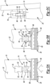
- the first latch component 76 includes an opening 80 and a pair of apertures 82 disposed on side surfaces of the latch component 76 and positioned substantially ninety degrees (90°) relative to the opening 80.
- the second latch mechanism 78 includes a locating tab 84 and a pair of latch elements 86 extending from a base 88.
- the second latch mechanism 78 may be formed from a resilient material such as, for example, plastic and may be movable from a relaxed state to a compressed state.
- the first latch component 76 may be positioned relative to the rail 32 such that when the second component 28 is moved the predetermined distance relative to the first component 26 and the distal end 16 of the prosthetic blade 12 engages the stop surface 58, the second latch component 78 is received by the first latch component 76.
- the locating tab 84 may enter the first latch component 74 and may guide the second latch component 78 into the first latch component 74.
- the second latch component 78 is sufficiently received by the first latch component 76, a force is applied to the latch elements 86 by walls 90 ( FIG. 5C ) of the first latch component 76 to move the latch elements 86 from the relaxed state to the compressed state.
- the latch elements 86 oppose respective ones of the apertures 82.
- the resilient nature of the material of the second latch component 78 causes the latch elements 86 to automatically return to the relaxed state and protrude from the apertures 82 ( FIG. 5B ).
- the first component 76 and the second component 78 are attached to one another and relative movement therebetween is restricted due to engagement between the latch elements 86 and the respective apertures 82. Accordingly, relative movement between the first component 26 and the second component 28 along the longitudinal axis (L) of the prosthetic blade 12 is restricted and the position of the sole structure 30 relative to the prosthetic blade 12 is maintained.
- the second latch component 78 may be removed from the first latch component 76 by applying a force on the latch elements 86 in a direction (X; FIG. 5B ). Applying a force on the latch elements 86 in the direction (X) moves the latch elements 86 from the relaxed state to the compressed state and removes the latch elements 86 from the apertures 82. Once the latch elements 86 are removed from the apertures 82, the second latch component 78 may be removed from the first latch component 76 by moving the second latch component 78-along with the second component 28 and sole structure 30—in a direction away from the first latch component 76. Removing the second latch component 78 from the first latch component 76 allows the channel 46 to move relative to and along the rail 32. Sufficient movement of the channel 46 relative to and along the rail 32 allows the channel 46 to disengage the rail 32. Once disengaged from the channel 46, the rail 32 may be attached to another of the sole structures 30, 30a, 30b, 30c.
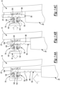
- FIGS. 6A-6C another latch mechanism 74a for use with the attachment system 10 is provided.
- like reference numerals are used hereinafter and in the drawings to identify like components while like reference numerals containing letter extensions are used to identify those components that have been modified.
- the latch mechanism 74a includes a first latch component 76a attached to the prosthetic blade 12 and a second latch component 78a attached to the second component 28. While the first latch component 76a is shown and described as being attached to the prosthetic blade 12 and the second latch component 78a is shown and described as being attached to the second component 28, the first latch component 76a could alternatively be attached to the second component 28 and the second latch component 78a could alternatively be attached to the prosthetic blade 12.
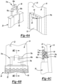
- the first latch component 76a includes a notch 92 having an engagement surface 94.
- the second latch mechanism 78a includes a latch element 86a extending from a base 88a.
- the second latch mechanism 78a may be formed from a resilient material such as, for example, plastic and may be movable from a relaxed state to a flexed state.
- the first latch component 76a may be positioned relative to the rail 32 such that when the second component 28 is moved the predetermined distance relative to the first component 26 and the distal end 16 of the prosthetic blade 12 engages the stop surface 58, the second latch component 78a is received by the first latch component 76a. Specifically, the latch element 86a is received by the notch 92 to fix a position of the second latch component 78a relative to the first latch component 76a.
- the latch element 86a is moved from the flexed state to the relaxed state and drops into the notch 92. Namely, a sloped surface 96 of the latch element 86a rides along the first latch component 76a and positions the latch element 86a in the flexed state. When the latch element 86a encounters the notch 92, the latch element 86a is automatically moved into the relaxed state due to the resilient nature of the material of the latch element 86a and drops into the notch 92.
- a latch surface 98 of the latch element 86a engages the engagement surface 94 of the first latch component 76a, thereby fixing a position of the first component 26 relative to the second component 28.
- the first component 76a and the second component 78a are attached to one another and relative movement therebetween is restricted due to engagement between the latch element 86a and the engagement surface 94. Accordingly, relative movement between the first component 26 and the second component 28 along the longitudinal axis (L) of the prosthetic blade 12 is restricted and the position of the sole structure 30 relative to the prosthetic blade 12 is maintained.
- the second latch component 78a may be removed from the first latch component 76a by applying a force on the latch element 86a in a direction (Y; FIG. 6C ). Applying a force on the latch element 86a in the direction (Y) moves the latch element 86a from the relaxed state to the flexed state and removes the latch element 86a from the notch 92. Once the latch element 86a is removed from the notch 92, the second latch component 78a may be removed from the first latch component 76a by moving the second latch component 78a-along with the second component 28 and sole structure 30—in a direction away from the first latch component 76a.
- Removing the second latch component 78a from the first latch component 76a allows the channel 46 to move relative to and along the rail 32. Sufficient movement of the channel 46 relative to and along the rail 32 allows the channel 46 to disengage the rail 32. Once disengaged from the channel 46, the rail 32 may be attached to another of the sole structures 30, 30a, 30b, 30c.
- FIGS. 7A-7C another latch mechanism 74b for use with the attachment system 10 is provided.
- like reference numerals are used hereinafter and in the drawings to identify like components while like reference numerals containing letter extensions are used to identify those components that have been modified.
- the latch mechanism 74b includes a first latch component 76b attached to the prosthetic blade 12 and a second latch component 78b attached to the second component 28. While the first latch component 76b is shown and described as being attached to the prosthetic blade 12 and the second latch component 78b is shown and described as being attached to the second component 28, the first latch component 76b could alternatively be attached to the second component 28 and the second latch component 78b could alternatively be attached to the prosthetic blade 12.
- the first latch component 76b includes a notch 92 having an engagement surface 94.
- the second latch mechanism 78b includes a latch element 86b extending from a base 88b.
- the second latch mechanism 78b may be formed from a resilient material such as, for example, plastic and may be movable from a relaxed state to a flexed state.
- the first latch component 76b may be positioned relative to the rail 32 such that when the second component 28 is moved the predetermined distance relative to the first component 26 and the distal end 16 of the prosthetic blade 12 engages the stop surface 58, the second latch component 78b is received by the first latch component 76b. Specifically, the latch element 86b is received by the notch 92 to fix a position of the second latch component 78b relative to the first latch component 76b. Alignment of the latch element 86b and the notch 92 may be further achieved by engaging projections 100 of the second latch component 78b with stops 102 of the first latch component 76b.
- the latch element 86b is moved from the flexed state to the relaxed state and drops into the notch 92. Namely, a sloped surface 96 of the latch element 86b rides along the first latch component 76b and positions the latch element 86b in the flexed state. When the latch element 86b encounters the notch 92, the latch element 86b is automatically moved into the relaxed state due to the resilient nature of the material of the latch element 86b and drops into the notch 92.
- a latch surface 98 of the latch element 86b engages the engagement surface 94 of the first latch component 76b, thereby fixing a position of the first component 26 relative to the second component 28.
- the first component 76b and the second component 78b are attached to one another and relative movement therebetween is restricted due to engagement between the latch element 86b and the engagement surface 94. Accordingly, relative movement between the first component 26 and the second component 28 along the longitudinal axis (L) of the prosthetic blade 12 is restricted and the position of the sole structure 30 relative to the prosthetic blade 12 is maintained.
- the second latch component 78b may be removed from the first latch component 76b by applying a force on the latch element 86b in a direction (W; FIG. 7D). Applying a force on the latch element 86b in the direction (W) moves the latch element 86b from the relaxed state to the flexed state and removes the latch element 86b from the notch 92. Once the latch element 86b is removed from the notch 92, the second latch component 78b may be removed from the first latch component 76b by moving the second latch component 78b-along with the second component 28 and sole structure 30—in a direction away from the first latch component 76b.
- Removing the second latch component 78b from the first latch component 76b allows the channel 46 to move relative to and along the rail 32. Sufficient movement of the channel 46 relative to and along the rail 32 allows the channel 46 to disengage the rail 32. Once disengaged from the channel 46, the rail 32 may be attached to another of the sole structures 30, 30a, 30b, 30c.
- FIGS. 8A-8C another latch mechanism 74c for use with the attachment system 10 is provided.
- like reference numerals are used hereinafter and in the drawings to identify like components while like reference numerals containing letter extensions are used to identify those components that have been modified.
- the latch mechanism 74c includes a first latch component 76c attached to the prosthetic blade 12 and a second latch component 78c attached to the second component 28. While the first latch component 76c is shown and described as being attached to the prosthetic blade 12 and the second latch component 78c is shown and described as being attached to the second component 28, the first latch component 76c could alternatively be attached to the second component 28 and the second latch component 78c could alternatively be attached to the prosthetic blade 12.
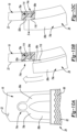
- the first latch component 76c includes a channel 104 having an engagement surface 94c and a ramped surface 106.
- the second latch mechanism 78c includes a latch element 86c extending from a base 88c.
- the second latch mechanism 78c may be formed from a resilient material such as, for example, plastic and may be movable from a relaxed state to a flexed state.
- the first latch component 76c may be positioned relative to the rail 32 such that when the second component 28 is moved the predetermined distance relative to the first component 26 and the distal end 16 of the prosthetic blade 12 engages the stop surface 58, the second latch component 78c is received by the first latch component 76c. Specifically, the latch element 86c is received by the channel 104 to fix a position of the second latch component 78c relative to the first latch component 76c.
- the latch element 86c is moved from the relaxed state to the flexed state when the sloped surface 96 engages the ramped surface 106.
- the latch element 86c remains in the flexed state until the latch element 86c traverses the channel 104 and the latch surface 98 engages the engagement surface 94c. Namely, the sloped surface 96 of the latch element 86c rides along the ramped surface 106 and positions the latch element 86c in the flexed state.
- the latch element 86c When the latch element 86c traverses the entire channel 104, the latch element 86c is automatically moved into the relaxed state due to the resilient nature of the material of the latch element 86c and is positioned in the configuration shown in FIG. 8C . In so doing, the latch surface 98 of the latch element 86c engages the engagement surface 94c of the first latch component 76c, thereby fixing a position of the first component 26 relative to the second component 28. At this point, the first component 76c and the second component 78c are attached to one another and relative movement therebetween is restricted due to engagement between the latch element 86c and the engagement surface 94c. Accordingly, relative movement between the first component 26 and the second component 28 along the longitudinal axis (L) of the prosthetic blade 12 is restricted and the position of the sole structure 30 relative to the prosthetic blade 12 is maintained.
- the second latch component 78c may be removed from the first latch component 76c by applying a force on the latch element 86c in a direction (Q; FIG. 8C ). Applying a force on the latch element 86c in the direction (Q) moves the latch element 86c from the relaxed state to the flexed state and removes the latch element 86c from engagement with the engagement surface 94c. Once the latch element 86c is removed from engagement with the engagement surface 94c, the second latch component 78c may be removed from the first latch component 76c by moving the second latch component 78c-along with the second component 28 and sole structure 30—in a direction away from the first latch component 76c.
- Removing the second latch component 78c from the first latch component 76c allows the channel 46 to move relative to and along the rail 32. Sufficient movement of the channel 46 relative to and along the rail 32 allows the channel 46 to disengage the rail 32. Once disengaged from the channel 46, the rail 32 may be attached to another of the sole structures 30, 30a, 30b, 30c.
- FIGS. 9A-9C another latch mechanism 74d for use with the attachment system 10 is provided.
- like reference numerals are used hereinafter and in the drawings to identify like components while like reference numerals containing letter extensions are used to identify those components that have been modified.
- the latch mechanism 74d includes a first latch component 76d attached to the prosthetic blade 12 and a second latch component 78d attached to the second component 28. While the first latch component 76d is shown and described as being attached to the prosthetic blade 12 and the second latch component 78d is shown and described as being attached to the second component 28, the first latch component 76d could alternatively be attached to the second component 28 and the second latch component 78d could alternatively be attached to the prosthetic blade 12.
- the second latch component 78d includes a latch element 86d extending from a base 88d.
- the second latch mechanism 78d may be formed from a resilient material such as, for example, plastic and/or rubber and may be movable from a relaxed state to a flexed state.
- the first latch component 76d may be positioned relative to the rail 32 such that when the second component 28 is moved the predetermined distance relative to the first component 26 and the distal end 16 of the prosthetic blade 12 engages the stop surface 58, the second latch component 78d is positioned proximate to the first latch component 76d.
- the latch element 86d opposes a projection 108 of the first latch component 76d and may be attached to the projection 108 to fix a position of the second latch component 78d relative to the first latch component 76d.
- the latch element 86d is moved from the relaxed state to the flexed state. Specifically, a force may be applied to the latch element 86d to move the latch element 86d from the relaxed state ( FIG. 9C ) to the flexed state ( FIGS. 9A and 9B ) and into engagement with the projection 108 of the first latch component 76d.
- the latch element 86d may include a hook 110 that is received by a recess 112 of the first latch component 76d when the latch element 86d is returned to the relaxed state.
- the first component 76d and the second component 78d are attached to one another and relative movement therebetween is restricted due to engagement between the hook 110 of the latch element 86d and the recess 110 of the first latch component 76d. Accordingly, relative movement between the first component 26 and the second component 28 along the longitudinal axis (L) of the prosthetic blade 12 is restricted and the position of the sole structure 30 relative to the prosthetic blade 12 is maintained.
- the second latch component 78d may be removed from the first latch component 76d by applying a force on the latch element 86d in a direction (R; FIG. 9C ). Applying a force on the latch element 86d in the direction (R) moves the latch element 86d from the relaxed state to the flexed state and removes the latch element 86d from engagement with the recess 112. Once the latch element 86d is removed from engagement with the recess 112, the second latch component 78d may be removed from the first latch component 76d by moving the second latch component 78d-along with the second component 28 and sole structure 30—in a direction away from the first latch component 76d.
- Removing the second latch component 78d from the first latch component 76d allows the channel 46 to move relative to and along the rail 32. Sufficient movement of the channel 46 relative to and along the rail 32 allows the channel 46 to disengage the rail 32. Once disengaged from the channel 46, the rail 32 may be attached to another of the sole structures 30, 30a, 30b, 30c.
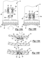
- FIGS. 10A-10C another latch mechanism 74e for use with the attachment system 10 is provided.
- like reference numerals are used hereinafter and in the drawings to identify like components while like reference numerals containing letter extensions are used to identify those components that have been modified.
- the latch mechanism 74e includes a first latch component 76e attached to the prosthetic blade 12 and a second latch component 78e attached to the second component 28. While the first latch component 76e is shown and described as being attached to the prosthetic blade 12 and the second latch component 78e is shown and described as being attached to the second component 28, the first latch component 76e could alternatively be attached to the second component 28 and the second latch component 78e could alternatively be attached to the prosthetic blade 12.
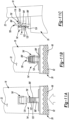
- the first latch component 76e includes a notch 92e having an engagement surface 94e ( FIG. 10B ) and a magnet 114 located on an opposite side of the first latch component 76e than the notch 92e. As shown in FIGS. 10B and 10C , the notch 92e and magnet 114 may be located on opposite sides of the body portion 18 of the prosthetic blade 12 such that the notch 92e is formed into the material of the body portion 18 and the magnet 114 is recessed into the body portion 18.
- the second latch mechanism 78e includes a projection 116 extending from a base 88e and including at least a portion formed from metal.
- the base 88e and at least a portion of the projection 116 of the second latch mechanism 78e may be formed from a resilient material such as, for example, plastic and may be movable from a relaxed state to a flexed state.
- the first latch component 76e may be positioned relative to the rail 32 such that when the second component 28 is moved the predetermined distance relative to the first component 26 and the distal end 16 of the prosthetic blade 12 engages the stop surface 58, the second latch component 78e is received by the first latch component 76e. Specifically, the latch element 86e is received by the notch 92e to fix a position of the second latch component 78e relative to the first latch component 76e.
- the latch element 86e is moved from the flexed state to the relaxed state and drops into the notch 92e. Namely, the projection 116 of the latch element 86e rides along the first latch component 76e and positions the latch element 86e in the flexed state. When the latch element 86e encounters the notch 92e, the latch element 86e is automatically moved into the relaxed state due to the resilient nature of the material of the latch element 86e and due to the magnet exerting a force on the projection 116 and drops into the notch 92e.
- a latch surface 98e of the latch element 86e engages the engagement surface 94e of the first latch component 76e, thereby fixing a position of the first component 26 relative to the second component 28.
- the first component 76e and the second component 78e are attached to one another and relative movement therebetween is restricted due to engagement between the latch element 86e and the engagement surface 94e. Accordingly, relative movement between the first component 26 and the second component 28 along the longitudinal axis (L) of the prosthetic blade 12 is restricted and the position of the sole structure 30 relative to the prosthetic blade 12 is maintained.
- the second latch component 78e may be removed from the first latch component 76e by applying a force on the latch element 86e in a direction (S; FIG. 10C ). Applying a force on the latch element 86e in the direction (S) moves the latch element 86e from the relaxed state to the flexed state and removes the latch element 86e from the notch 92e. Once the latch element 86e is removed from the notch 92e, the second latch component 78e may be removed from the first latch component 76e by moving the second latch component 78e-along with the second component 28 and sole structure 30—in a direction away from the first latch component 76e.
- Removing the second latch component 78e from the first latch component 76e allows the channel 46 to move relative to and along the rail 32. Sufficient movement of the channel 46 relative to and along the rail 32 allows the channel 46 to disengage the rail 32. Once disengaged from the channel 46, the rail 32 may be attached to another of the sole structures 30, 30a, 30b, 30c.
- FIGS. 11A-11C another latch mechanism 74f for use with the attachment system 10 is provided.
- like reference numerals are used hereinafter and in the drawings to identify like components while like reference numerals containing letter extensions are used to identify those components that have been modified.
- the latch mechanism 74f includes a first latch component 76f attached to the prosthetic blade 12 and a second latch component 78f attached to the second component 28. While the first latch component 76f is shown and described as being attached to the prosthetic blade 12 and the second latch component 78f is shown and described as being attached to the second component 28, the first latch component 76f could alternatively be attached to the second component 28 and the second latch component 78f could alternatively be attached to the prosthetic blade 12.
- the first latch component 76f includes a channel 104f and a projection 118 including an engagement surface 94f formed at a distal end thereof extending into the channel 104f.
- the second latch mechanism 78f includes a latch element 86f extending from a base 88f and including a series of peaks 120 and depressions 122 formed between adjacent peaks 120.
- the first latch component 76f may be positioned relative to the rail 32 such that when the second component 28 is moved the predetermined distance relative to the first component 26 and the distal end 16 of the prosthetic blade 12 engages the stop surface 58, the second latch component 78f is received by the first latch component 76f. Specifically, the latch element 86f is received by the channel 104f to fix a position of the second latch component 78f relative to the first latch component 76f.
- the latch element 86f is moved into engagement with the engagement surface 94f of the projection 118.
- the projection 118 moves along the latch element 86f and is received within depressions 122 formed between adjacent peaks 120.
- the latch element 86f may be received within any of the depressions 122 depending on the extent to which the latch element 86f extends into the channel 104f.
- the second latch component 78f may be removed from the first latch component 76f by applying a force on a release tab 124 to depress the release tab 124 and remove the projection 118 from engagement with the depressions 120. Specifically, the applied force causes the projection 118 to move in the direction (T) and away from the latch element 86f. Once the engagement surface 94f of the projection 118 is removed from engagement with the latch element 86f, the second latch component 78f may be removed from the first latch component 76f by moving the second latch component 78f-along with the second component 28 and sole structure 30—in a direction away from the first latch component 76f. Removing the second latch component 78f from the first latch component 76f allows the channel 46 to move relative to and along the rail 32. Sufficient movement of the channel 46 relative to and along the rail 32 allows the channel 46 to disengage the rail 32. Once disengaged from the channel 46, the rail 32 may be attached to another of the sole structures 30, 30a, 30b, 30c.
- FIGS. 12A-12B another latch mechanism 74g for use with the attachment system 10 is provided.
- like reference numerals are used hereinafter and in the drawings to identify like components while like reference numerals containing letter extensions are used to identify those components that have been modified.
- the latch mechanism 74g includes a first latch component 76g attached to the prosthetic blade 12 and a second latch component 78g attached to the second component 28. While the first latch component 76g is shown and described as being attached to the prosthetic blade 12 and the second latch component 78g is shown and described as being attached to the second component 28, the first latch component 76g could alternatively be attached to the second component 28 and the second latch component 78g could alternatively be attached to the prosthetic blade 12.
- the first latch component 76g includes a buckle 126.
- the first latch component 76g may be positioned relative to the rail 32 such that when the second component 28 is moved the predetermined distance relative to the first component 26 and the distal end 16 of the prosthetic blade 12 engages the stop surface 58, the second latch component 78g is positioned proximate to the first latch component 76g.
- the buckle 126 receives a belt portion 128 of the second latch component 78g and may be attached to the belt portion 128 to fix a position of the second latch component 78g relative to the first latch component 76g.
- the buckle 124 may include a post 130 that is received by one of a series of apertures 132 associated with the belt portion 128.
- the position of the belt portion 128 relative to the buckle 126 is substantially fixed.
- the first latch component 76g and the second latch component 78g are attached to one another and relative movement therebetween is restricted due to engagement between the buckle 126 and the belt portion 128. Accordingly, relative movement between the first component 26 and the second component 28 along the longitudinal axis (L) of the prosthetic blade 12 is restricted and the position of the sole structure 30 relative to the prosthetic blade 12 is maintained.
- the second latch component 78g may be removed from the first latch component 76g by applying a force on the post 130 to remove the post 120 from the belt portion 128. Once the post 130 is removed from engagement with the belt portion 128, the second latch component 78g may be removed from the first latch component 76g by moving the second latch component 78g-- along with the second component 28 and sole structure 30—in a direction away from the first latch component 76g. Removing the second latch component 78g from the first latch component 76g allows the channel 46 to move relative to and along the rail 32. Sufficient movement of the channel 46 relative to and along the rail 32 allows the channel 46 to disengage the rail 32. Once disengaged from the channel 46, the rail 32 may be attached to another of the sole structures 30, 30a, 30b, 30c.
- FIGS. 13A-13B another latch mechanism 74h for use with the attachment system 10 is provided.
- like reference numerals are used hereinafter and in the drawings to identify like components while like reference numerals containing letter extensions are used to identify those components that have been modified.
- the latch mechanism 74h includes a first latch component 76h attached to the prosthetic blade 12 and a second latch component 78h attached to the second component 28. While the first latch component 76h is shown and described as being attached to the prosthetic blade 12 and the second latch component 78h is shown and described as being attached to the second component 28, the first latch component 76h could alternatively be attached to the second component 28 and the second latch component 78h could alternatively be attached to the prosthetic blade 12.
- the first latch component 76h includes a latch post 134.
- the first latch component 76h may be positioned relative to the rail 32 such that when the second component 28 is moved the predetermined distance relative to the first component 26 and the distal end 16 of the prosthetic blade 12 engages the stop surface 58, the second latch component 78h is positioned proximate to the first latch component 76h.
- the latch post 134 may be inserted into one of a series of apertures 132 of the belt portion 128 to fix a position of the second latch component 78h relative to the first latch component 76h.
- the position of the belt portion 128 relative to the first latch component 76h is substantially fixed.
- the first latch component 76h and the second latch component 78h are attached to one another and relative movement therebetween is restricted due to engagement between the latch post 134 and the belt portion 128. Accordingly, relative movement between the first component 26 and the second component 28 along the longitudinal axis (L) of the prosthetic blade 12 is restricted and the position of the sole structure 30 relative to the prosthetic blade 12 is maintained.
- the second latch component 78h may be removed from the first latch component 76h by removing the latch post 134 from the belt portion 128. Once the post 134 is removed from engagement with the belt portion 128, the second latch component 78h may be removed from the first latch component 76h by moving the second latch component 78h-along with the second component 28 and sole structure 30—in a direction away from the first latch component 76h. Removing the second latch component 78h from the first latch component 76h allows the channel 46 to move relative to and along the rail 32. Sufficient movement of the channel 46 relative to and along the rail 32 allows the channel 46 to disengage the rail 32. Once disengaged from the channel 46, the rail 32 may be attached to another of the sole structures 30, 30a, 30b, 30c.
- FIGS. 14A-14C another latch mechanism 74i for use with the attachment system 10 is provided.
- like reference numerals are used hereinafter and in the drawings to identify like components while like reference numerals containing letter extensions are used to identify those components that have been modified.
- the latch mechanism 74i includes a first latch component 76i attached to the prosthetic blade 12 and a second latch component 78i attached to the second component 28. While the first latch component 76i is shown and described as being attached to the prosthetic blade 12 and the second latch component 78i is shown and described as being attached to the second component 28, the first latch component 76i could alternatively be attached to the second component 28 and the second latch component 78i could alternatively be attached to the prosthetic blade 12.
- the first latch component 76i includes a channel 104i and a recess 136 in communication with the channel 104i.
- the second latch mechanism 78i includes a latch element 86i in selective engagement with a plunger 140.
- the plunger 140 is disposed within the recess 136 and extends into the channel 104i.
- the plunger 140 is biased in the direction (M) shown in FIG. 14B by a biasing member 142.
- the biasing member 142 may be a coil spring that acts on the plunger 142 to bias the plunger 140 into the channel 104i.
- the first latch component 76i may be positioned relative to the rail 32 such that when the second component 28 is moved the predetermined distance relative to the first component 26 and the distal end 16 of the prosthetic blade 12 engages the stop surface 58, the second latch component 78i is received by the first latch component 76i. Specifically, the latch element 86i is received by the channel 104i to fix a position of the second latch component 78i relative to the first latch component 76i.
- the latch element 86i is moved into the channel 104i and into engagement with the plunger 140. Namely, the latch element 86i moves the plunger 140 in a direction opposite to direction (M) upon first entering the channel 104i. Once movement of the latch element 86i into the channel 104i is stopped due to the distal end 16 of the prosthetic blade 12 engaging the stop surface 58, the plunger 140 is received by one of a series of detents 138 formed in the latch element 86i.
- the second latch component 78i may be removed from the first latch component 76i by applying a force on the plunger 140 in a direction opposite to direction (M) and against the force exerted on the plunger 140 by the biasing member 142. Once the plunger 140 is removed from the detent 138, the second latch component 78i may be removed from the first latch component 76i by moving the second latch component 78i-along with the second component 28 and sole structure 30—in a direction away from the first latch component 76i. Removing the second latch component 78i from the first latch component 76i allows the channel 46 to move relative to and along the rail 32. Sufficient movement of the channel 46 relative to and along the rail 32 allows the channel 46 to disengage the rail 32. Once disengaged from the channel 46, the rail 32 may be attached to another of the sole structures 30, 30a, 30b, 30c.
- FIGS. 15A-15C another latch mechanism 74j for use with the attachment system 10 is provided.
- like reference numerals are used hereinafter and in the drawings to identify like components while like reference numerals containing letter extensions are used to identify those components that have been modified.
- the latch mechanism 74j includes a first latch component 76j attached to the prosthetic blade 12 and a second latch component 78j attached to the second component 28. While the first latch component 76j is shown and described as being attached to the prosthetic blade 12 and the second latch component 78j is shown and described as being attached to the second component 28, the first latch component 76j could alternatively be attached to the second component 28 and the second latch component 78j could alternatively be attached to the prosthetic blade 12.
- the first latch component 76j includes a recess 144 receiving a ball 146 and a biasing member 148 therein.
- the biasing member 148 biases the ball 146 in a direction (N) in a direction away from the recess 144.
- the second latch mechanism 78j includes a socket 150 extending into the second latch component 78j .
- the first latch component 76j may be positioned relative to the rail 32 such that when the second component 28 is moved the predetermined distance relative to the first component 26 and the distal end 16 of the prosthetic blade 12 engages the stop surface 58, the ball 146 is automatically received by socket 150 due to the biasing force exerted on the ball 146 by the biasing member 148.
- the second latch component 78j may disengaged from the ball 146 by moving the second latch component 78j-along with the second component 28 and sole structure 30—in a direction away from the first latch component 76j. Removing the socket 150 from the ball 146 allows the channel 46 to move relative to and along the rail 32. Sufficient movement of the channel 46 relative to and along the rail 32 allows the channel 46 to disengage the rail 32. Once disengaged from the channel 46, the rail 32 may be attached to another of the sole structures 30, 30a, 30b, 30c.
- FIGS. 16A-16C another latch mechanism 74k for use with the attachment system 10 is provided.
- like reference numerals are used hereinafter and in the drawings to identify like components while like reference numerals containing letter extensions are used to identify those components that have been modified.
- the latch mechanism 74k includes a first latch component 76k attached to the prosthetic blade 12 and a second latch component 78k attached to the second component 28. While the first latch component 76k is shown and described as being attached to the prosthetic blade 12 and the second latch component 78k is shown and described as being attached to the second component 28, the first latch component 76k could alternatively be attached to the second component 28 and the second latch component 78k could alternatively be attached to the prosthetic blade 12.
- the first latch component 76k includes a channel 104k and a recess 136k in communication with the channel 104k.
- the second latch mechanism 78k includes a latch element 86k in selective engagement with a plunger 140k.
- the plunger 140k is disposed within the recess 136k and extends into the channel 104k.
- the plunger 140k is biased in the direction (O) shown in FIG. 16A by a biasing member 142k.
- the biasing member 142k may be a coil spring that acts on the plunger 142k to bias the plunger 140k into the channel 104k.
- the first latch component 76k may be positioned relative to the rail 32 such that when the second component 28 is moved the predetermined distance relative to the first component 26 and the distal end 16 of the prosthetic blade 12 engages the stop surface 58, the second latch component 78k is received by the first latch component 76k. Specifically, the latch element 86k is received by the channel 104k to fix a position of the second latch component 78k relative to the first latch component 76k.
- the latch element 86k is moved into the channel 104k and into engagement with the plunger 140k. Namely, the latch element 86k moves the plunger 140k in a direction opposite to direction (O) upon first entering the channel 104k at a rounded, distal end 152 of the latch element 86k. Once movement of the latch element 86k into the channel 104k is stopped due to the distal end 16 of the prosthetic blade 12 engaging the stop surface 58, the plunger 140k is received by an aperture 154 formed in the latch element 86k.
- first component 76k and the second component 78k are attached to one another and relative movement therebetween is restricted. Accordingly, relative movement between the first component 26 and the second component 28 along the longitudinal axis (L) of the prosthetic blade 12 is restricted and the position of the sole structure 30 relative to the prosthetic blade 12 is maintained.
- the second latch component 78k may be removed from the first latch component 76k by applying a force on the plunger 140k in a direction opposite to direction (O) and against the force exerted on the plunger 140k by the biasing member 142k. Once the plunger 140k is removed from the aperture 154, the second latch component 78k may be removed from the first latch component 76k by moving the second latch component 78k-along with the second component 28 and sole structure 30—in a direction away from the first latch component 76k. Removing the second latch component 78k from the first latch component 76k allows the channel 46 to move relative to and along the rail 32. Sufficient movement of the channel 46 relative to and along the rail 32 allows the channel 46 to disengage the rail 32. Once disengaged from the channel 46, the rail 32 may be attached to another of the sole structures 30, 30a, 30b, 30c.
- FIGS. 17A-17C another latch mechanism 74l for use with the attachment system 10 is provided.
- like reference numerals are used hereinafter and in the drawings to identify like components while like reference numerals containing letter extensions are used to identify those components that have been modified.
- the latch mechanism 74l includes a first latch component 76l attached to the prosthetic blade 12 and a second latch component 78l attached to the second component 28. While the first latch component 76l is shown and described as being attached to the prosthetic blade 12 and the second latch component 78l is shown and described as being attached to the second component 28, the first latch component 76l could alternatively be attached to the second component 28 and the second latch component 78l could alternatively be attached to the prosthetic blade 12.
- the first latch component 76l includes a post 156 having a pair of projections 158 defining a pair of detents 160.
- the second latch component 76l includes a pair of extensions 162 formed from a flexible material and extending into a channel 164.
- the first latch component 76l may be positioned relative to the rail 32 such that when the second component 28 is moved the predetermined distance relative to the first component 26 and the distal end 16 of the prosthetic blade 12 engages the stop surface 58, the second latch component 78l receives the first latch component 76l.
- the post 156 is received by the channel 164 with the extensions 162 sliding along respective outer surfaces 168 of the post 156. Because the extensions 162 are formed from a flexible material, the extensions 162 bend into the shape shown in FIG. 17A . The extensions 162, upon encountering the projections 158 bend further until being received within respective detents 160. At this point, a position of the second latch component 78l relative to the first latch component 76l is fixed.
- the second latch component 78l may be removed from the first latch component 76l by moving the second latch component 78l-along with the second component 28 and sole structure 30—in a direction away from the first latch component 76l to allow the extensions 162 to disengage the detents 160 and once again slide along the surfaces 168 of the post 156. Removing the second latch component 78l from the first latch component 76lk allows the channel 46 to move relative to and along the rail 32. Sufficient movement of the channel 46 relative to and along the rail 32 allows the channel 46 to disengage the rail 32. Once disengaged from the channel 46, the rail 32 may be attached to another of the sole structures 30, 30a, 30b, 30c.
- FIGS. 18A-18C another latch mechanism 74m for use with the attachment system 10 is provided.
- like reference numerals are used hereinafter and in the drawings to identify like components while like reference numerals containing letter extensions are used to identify those components that have been modified.
- the latch mechanism 74m includes a first latch component 76m attached to the prosthetic blade 12 and a second latch component 78m attached to the second component 28. While the first latch component 76m is shown and described as being attached to the prosthetic blade 12 and the second latch component 78m is shown and described as being attached to the second component 28, the first latch component 76m could alternatively be attached to the second component 28 and the second latch component 78m could alternatively be attached to the prosthetic blade 12.
- the first latch component 76m includes a cage 170 including an opening 172 and a pair of spring members 174 disposed therein.
- the second latch component 76m includes a latch element 86m having a shape that approximates a shape of the opening 172.
- the first latch component 76m may be positioned relative to the rail 32 such that when the second component 28 is moved the predetermined distance relative to the first component 26 and the distal end 16 of the prosthetic blade 12 engages the stop surface 58, the second latch component 78m is received by the cage 170. Specifically, the latch element 78m is positioned above the opening 172 and exerts a force on the spring members 174, thereby causing the spring members 174 to move away from one another. Once fully seated, the latch element 78m is retained within the opening 172 by the spring members 174 acting on the latch element 78m in a direction toward one another. At this point, a position of the second latch component 78m relative to the first latch component 76m is fixed.
- the second latch component 78m may be removed from the first latch component 76m by moving the second latch component 78m-along with the second component 28 and sole structure 30—in a direction away from the first latch component 76m to allow the latch element 78m to disengage the spring members 174 and be removed from the opening 172. Removing the second latch component 78m from the first latch component 76m allows the channel 46 to move relative to and along the rail 32. Sufficient movement of the channel 46 relative to and along the rail 32 allows the channel 46 to disengage the rail 32. Once disengaged from the channel 46, the rail 32 may be attached to another of the sole structures 30, 30a, 30b, 30c.
- FIGS. 19A-19C another latch mechanism 74n for use with the attachment system 10 is provided.
- like reference numerals are used hereinafter and in the drawings to identify like components while like reference numerals containing letter extensions are used to identify those components that have been modified.
- the latch mechanism 74n includes a first latch component 76n attached to the prosthetic blade 12 and a second latch component 78n attached to the second component 28. While the first latch component 76n is shown and described as being attached to the prosthetic blade 12 and the second latch component 78n is shown and described as being attached to the second component 28, the first latch component 76n could alternatively be attached to the second component 28 and the second latch component 78n could alternatively be attached to the prosthetic blade 12.
- the first latch component 76n includes a recess 176 having a post 178 disposed therein.
- the post 178 includes a ball 180 disposed at a distal end thereof.
- the second latch component 78n includes a pair of engagement blocks 182 biased toward one another by a pair of biasing members 184.
- the biasing members 184 are coil springs.
- the first latch component 76n may be positioned relative to the rail 32 such that when the second component 28 is moved the predetermined distance relative to the first component 26 and the distal end 16 of the prosthetic blade 12 engages the stop surface 58, the second latch component 78n is received by the recess 176.
- the ball 180 engages the engagement blocks 182, thereby causing the engagement blocks 182 to move away from one another against the bias of the biasing members 184.
- the engagement blocks 182 may each include a depression 186 sized to mate with the outer perimeter of the ball 180. As such, engagement between the engagement blocks 182 and the ball 180 maintains the second latch component 78n in contact with the first latch component 76n. At this point, a position of the second latch component 78n relative to the first latch component 76n is fixed.
- the second latch component 78n may be removed from the first latch component 76n by moving the second latch component 78n-along with the second component 28 and sole structure 30—in a direction away from the first latch component 76n to allow engagement blocks 182 to disengage the ball 180 and be removed from the opening recess 176. Removing the second latch component 78n from the first latch component 76n allows the channel 46 to move relative to and along the rail 32. Sufficient movement of the channel 46 relative to and along the rail 32 allows the channel 46 to disengage the rail 32. Once disengaged from the channel 46, the rail 32 may be attached to another of the sole structures 30, 30a, 30b, 30c.
Landscapes
- Health & Medical Sciences (AREA)
- Transplantation (AREA)
- Heart & Thoracic Surgery (AREA)
- Oral & Maxillofacial Surgery (AREA)
- Engineering & Computer Science (AREA)
- Biomedical Technology (AREA)
- Cardiology (AREA)
- Vascular Medicine (AREA)
- Life Sciences & Earth Sciences (AREA)
- Animal Behavior & Ethology (AREA)
- General Health & Medical Sciences (AREA)
- Public Health (AREA)
- Veterinary Medicine (AREA)
- Orthopedic Medicine & Surgery (AREA)
- Prostheses (AREA)
Description
- The present disclosure relates to attachment systems and more particularly to an attachment system for securing to a prosthetic device a component having a ground-contacting surface.
- This section provides background information related to the present disclosure and is not necessarily prior art.
- Prosthetic devices are used by amputees to replace all of, or some portion of, a limb. For example, prosthetic legs may be used to replace a portion of a person's leg surgically removed at or above the knee. Such prosthetic devices allow the person to walk in a conventional manner by supporting the person's weight and, in some cases, by providing a prosthetic joint at the person's knee that bends and otherwise mimics operation of a human knee. Prosthetic legs may be incorporated at one or both of the person's legs depending on the person's condition.
- Prosthetic legs may be used in conjunction with prosthetic feet that are designed to replace the foot of the amputee. As with prosthetic legs, prosthetic feet are designed to allow an amputee to walk in a conventional manner by supporting the person's weight during use.
Prosthetic feet are sometimes also designed to flex and bend in an effort to function in a similar manner as a human ankle and foot. - One conventional prosthetic foot is a so-called prosthetic blade that includes a substantially flat member extending from a distal end of a prosthetic leg. Prosthetic blades are typically formed from a resilient material that permits the blade to bend and flex during use while automatically returning to a relaxed state once an applied force is released. Such bending and flexing of the prosthetic blade is enhanced by the generally curved shape of the blade that facilitates bending and flexing when the blade comes in contact with the ground during use. The foregoing properties of prosthetic blades allow the blades to absorb energy associated with ground-contacting forces and, as such, provide an amputee with a degree of comfort during use. Further, such bending and flexing provides the amputee with an energy return during walking and running movements that enhances the performance of the amputee during such movements.
- While prosthetic blades provide an amputee with the ability to walk and run, such blades do not typically include a ground-contacting surface suitable for all potential activities. Accordingly, prosthetic blades may be fitted with an outsole that is affixed to the blade using an adhesive to restrict relative movement between the material of the blade and the material of the outsole. While such outsoles protect the blade during use and, further, enhance the traction of the blade with the ground during some uses, such outsoles are difficult to attach and, further, are even more difficult to remove. Accordingly, the few outsoles currently used in conjunction with prosthetic blades cannot be easily interchanged with one another for use in a particular activity or with a particular ground surface.
WO 2005/041819 A2 discloses a prosthetic foot having an adjustable ankle, and having upper and lower portions.
GB 978 586
WO 98/40038 A1
US 8 535 390 B1 discloses a traction device for a prosthetic running foot having a curved profile and mechanisms for attaching the traction device to the prosthetic running foot. - The drawings described herein are for illustrative purposes only of selected configurations and not all possible implementations, and are not intended to limit the scope of the present disclosure.
-
FIG. 1 is a perspective view of a prosthetic device; -
FIG. 2 is an exploded perspective view of the prosthetic device ofFIG. 1 showing a first component of an attachment system separated from a second component of the attachment system; -
FIG. 3A is a side view of the prosthetic device ofFIG. 1 ; -
FIG. 3B is a cross-sectional view of the prosthetic device ofFIG. 1 taken alongline 3B-3B ofFIG. 3A ; -
FIG. 4A is a perspective view of a sole structure for use with the prosthetic device ofFIG. 1 ; -
FIG. 4B is a perspective view of a sole structure for use with the prosthetic device ofFIG. 1 ; -
FIG. 4C is a perspective view of a sole structure for use with the prosthetic device ofFIG. 1 ; -
FIG. 5A is a top view of a latch mechanism for use with the prosthetic device ofFIG. 1 shown in an unlatched state; -
FIG. 5B is a top view of the latch mechanism ofFIG. 5A shown in a latched state; -
FIG. 5C is a side view of the latch mechanism ofFIG. 5A shown in a latched state; -
FIG. 6A a partial exploded perspective view of a latch mechanism for use with the prosthetic device ofFIG. 1 shown in an unlatched state; -
FIG. 6B is a top view of the latch mechanism ofFIG. 6A shown in a latched state; -
FIG. 6C is a partial cross-sectional view of the latch mechanism ofFIG. 6A taken alongline 6C-6C ofFIG. 6B and shown in a latched state; -
FIG. 7A a partial exploded perspective view of a latch mechanism for use with the prosthetic device ofFIG. 1 shown in an unlatched state; -
FIG. 7B is a top view of the latch mechanism ofFIG. 7A shown in a latched state; -
FIG. 7C is a partial cross-sectional view of the latch mechanism ofFIG. 7A taken alongline 7C-7C ofFIG. 7B and shown in a latched state; -
FIG. 8A is a partial cross-sectional view of a latch mechanism for use with the prosthetic device ofFIG. 1 shown in an unlatched state; -
FIG. 8B is a partial cross-sectional view of the latch mechanism ofFIG. 8A moving from an unlatched state toward a latched state; -
FIG. 8C is a partial cross-sectional view of the latch mechanism ofFIG. 8A shown in a latched state; -
FIG. 9A is a partial cross-sectional view of a latch mechanism for use with the prosthetic device ofFIG. 1 shown in an unlatched state; -
FIG. 9B is a partial cross-sectional view of the latch mechanism ofFIG. 9A moving from an unlatched state toward a latched state; -
FIG. 9C is a partial cross-sectional view of the latch mechanism ofFIG. 9A shown in a latched state; -
FIG. 10A is a top view of a latch mechanism for use with the prosthetic device ofFIG. 1 ; -
FIG. 10B is a partial cross-sectional view of the latch mechanism ofFIG. 10A moving from an unlatched state toward a latched state; -
FIG. 10C is a partial cross-sectional view of the latch mechanism ofFIG. 10A in a latched state; -
FIG. 11A a top view of a latch mechanism for use with the prosthetic device ofFIG. 1 shown in an unlatched state; -
FIG. 11B is a top view of the latch mechanism ofFIG. 11B shown in a latched state; -
FIG. 11C is a partial cross-sectional view of the latch mechanism ofFIG. 11A taken along line 11C-11C ofFIG. 11B and shown in the latched state; -
FIG. 12A is a top view of a latch mechanism for use with the prosthetic device ofFIG. 1 shown in an unlatched state; -
FIG. 12B is a top view of the latch mechanism ofFIG. 12A shown in a latched state; -
FIG. 13A is a top view of a latch mechanism for use with the prosthetic device ofFIG. 1 shown in an unlatched state; -
FIG. 13B is a top view of the latch mechanism ofFIG. 13A shown in a latched state; -
FIG. 14A is a partial cross-sectional view of a latch mechanism for use with the prosthetic device ofFIG. 1 shown in an unlatched state; -
FIG. 14B is a partial cross-sectional view of the latch mechanism ofFIG. 14A moving from an unlatched state toward a latched state; -
FIG. 14C is a partial cross-sectional view of the latch mechanism ofFIG. 14A shown in a latched state; -
FIG. 15A is a partial cross-sectional view of a latch mechanism for use with the prosthetic device ofFIG. 1 shown in an unlatched state; -
FIG. 15B is a partial cross-sectional view of the latch mechanism ofFIG. 15A moving from an unlatched state toward a latched state; -
FIG. 15C is a partial cross-sectional view of the latch mechanism ofFIG. 15A shown in a latched state; -
FIG. 16A is a partial cross-sectional view of a latch mechanism for use with the prosthetic device ofFIG. 1 shown in an unlatched state; -
FIG. 16B is a partial cross-sectional view of the latch mechanism ofFIG. 16A shown in a latched state; -
FIG. 17A is a top view of a latch mechanism for use with the prosthetic device ofFIG. 1 shown in an unlatched state; -
FIG. 17B is a top view of the latch mechanism ofFIG. 17A shown in a latched state; -
FIG. 18A is a top view of a latch mechanism for use with the prosthetic device ofFIG. 1 shown in an unlatched state; -
FIG. 18B is a top view of the latch mechanism ofFIG. 18A shown in a latched state; -
FIG. 19A is a partial cross-sectional view of a latch mechanism for use with the prosthetic device ofFIG. 1 shown in an unlatched state; and -
FIG. 19B is a partial cross-sectional view of the latch mechanism ofFIG. 19A shown in a latched state. - Corresponding reference numerals indicate corresponding parts throughout the drawings.
- Example configurations will now be described more fully with reference to the accompanying drawings. Example configurations are provided so that this disclosure will be thorough, and will fully convey the scope of the disclosure to those of ordinary skill in the art. Specific details are set forth such as examples of specific components, devices, and methods, to provide a thorough understanding of configurations of the present disclosure. It will be apparent to those of ordinary skill in the art that specific details need not be employed, that example configurations may be embodied in many different forms, and that the specific details and the example configurations should not be construed to limit the scope of the disclosure.
- The terminology used herein is for the purpose of describing particular exemplary configurations only and is not intended to be limiting. As used herein, the singular articles "a," "an," and "the" may be intended to include the plural forms as well, unless the context clearly indicates otherwise. The terms "comprises," "comprising," "including," and "having," are inclusive and therefore specify the presence of features, steps, operations, elements, and/or components, but do not preclude the presence or addition of one or more other features, steps, operations, elements, components, and/or groups thereof. The method steps, processes, and operations described herein are not to be construed as necessarily requiring their performance in the particular order discussed or illustrated, unless specifically identified as an order of performance. Additional or alternative steps may be employed.
- When an element or layer is referred to as being "on," "engaged to," "connected to," "attached to," or "coupled to" another element or layer, it may be directly on, engaged, connected, attached, or coupled to the other element or layer, or intervening elements or layers may be present. In contrast, when an element is referred to as being "directly on," "directly engaged to," "directly connected to," "directly attached to," or "directly coupled to" another element or layer, there may be no intervening elements or layers present. Other words used to describe the relationship between elements should be interpreted in a like fashion (e.g., "between" versus "directly between," "adjacent" versus "directly adjacent," etc.). As used herein, the term "and/or" includes any and all combinations of one or more of the associated listed items.
- The terms first, second, third, etc. may be used herein to describe various elements, components, regions, layers and/or sections. These elements, components, regions, layers and/or sections should not be limited by these terms. These terms may be only used to distinguish one element, component, region, layer or section from another region, layer or section. Terms such as "first," "second," and other numerical terms do not imply a sequence or order unless clearly indicated by the context. Thus, a first element, component, region, layer or section discussed below could be termed a second element, component, region, layer or section without departing from the teachings of the example configurations.
- An attachment system for use with a prosthetic device is provided. The attachment system includes a first component including a first surface, and further including one of a channel and a projection disposed on an opposite side of the first component than the first surface. The system also includes a second component including a second surface, and further including the other of the channel and the projection disposed on an opposite side of the second component than the second surface, the other of the channel and the projection slidably engaging the one of the channel and the projection to selectively couple the first component and the second component together. One of the first surface and the second surface is operable to be attached to the prosthetic device, and the other of the first surface and the second surface is operable to be attached to a sole structure having a ground-engaging surface.
- Implementations of the disclosure may include one or more of the following optional features. In some implementations, the channel matingly receives the projection therein. The projection may include a first portion that is disposed at a junction of the prosthetic device and the one of the first surface and the second surface and a second portion that is spaced apart from the first portion and is received by the channel, whereby the projection has a cross-section that is wider at the second portion than at the first portion to restrict removal of the projection from the channel. The channel and the projection may cooperate to selectively provide a dovetail connection between the first component and the second component.
- The sole structure may include a cushioning layer disposed between the other of the first surface and the second surface and the ground-engaging surface. In some examples, the ground-engaging surface is formed by the cushioning layer. The ground-engaging surface may be formed by an outsole layer that is attached to the cushioning layer.
- In some implementations, the attachment system includes a latch mechanism operable to fix a relative position between the first component and the second component. The latch mechanism may be automatically moved into a latched state to fix the relative position between the first component and the second component when the projection is moved into the channel a predetermined distance. The latch mechanism may include a male component that is fixed for movement with one of the first component and the second component and a female component that is fixed for movement with the other of the first component and the second component, the female component receiving the male component and securing the male component to the female component when the projection is moved the predetermined distance into the channel. The latch mechanism may also include a latching element fixed for movement with one of the first component and the second component, and further includes a latching feature fixed for movement with the other of the first component and the second component, the latching element operable to be actuated by and to engage the latching feature in response to a sliding engagement between the first component and the second component. The other of the first component and the second component may include a ramping surface operable to deflect the latching element and to position the latching element into engagement with the latching feature in response to the one of the first component and the second component slidingly engaging with the other of the first component and the second component.
- In some examples, the prosthetic device is a foot prosthetic device or the prosthetic device may be a blade prosthetic device. The first component and the second component may be elongated components.
- Another aspect of the disclosure provides an attachment system for use with a prosthetic device. The attachment includes a first elongate component attached to the prosthetic device and a second elongate component attached to a sole structure having a ground-engaging surface. The second elongate component slidably engages the first elongate component to attach the sole structure to the prosthetic device.
- This aspect may include one or more of the following optional features. In some implementations, the second elongate component matingly receives the first elongate component therein. The first elongate component may include a projection extending from a surface of the prosthetic device. The projection may include a first portion disposed at a junction of the projection and the surface of the prosthetic device and a second portion that is spaced apart from the first portion and is received by a channel. A cross-section of the projection may be wider at the second portion than at the first portion. The channel and the projection may cooperate to selectively provide a dovetail connection between the first elongate component and the second elongate component. In some examples, the sole structure includes a cushioning layer disposed between the second elongate component and the ground-engaging surface. The ground-engaging surface may be formed by the cushioning layer. The ground-engaging surface may be formed by an outsole layer that is attached to the cushioning layer.
- In some implementations, the attachment system includes a latch mechanism operable to selectively fix a relative position between the first elongate component and the second elongate component. The latch mechanism may be automatically moved into a latched state to fix the relative position between the first elongate component and the second elongate component when the first elongate component is moved into the second elongate component a predetermined distance. The latch mechanism may include a male component that is fixed for movement with one of the first elongate component and the second elongate component, and further includes a female component that is fixed for movement with the other of the first elongate component and the second elongate component. The female component may receive the male component and secure the male component to the female component when the first elongate component is moved the predetermined distance into the second elongate component. In some examples, the latch mechanism includes a latching element fixed for movement with one of the first elongate component and the second elongate component, and a latching feature fixed for movement with the other of the first elongate component and the second elongate component. The latching element may be operable to be moved relative to the one of the first elongate component and the second elongate component to engage the latching feature.
- In some examples, the other of the first elongate component and the second elongate component includes a ramping surface operable to deflect the latching element and to position the latching element into engagement with the latching feature. The prosthetic device may be a foot prosthetic device. The prosthetic device may be a blade prosthetic device, in some examples. The first elongate component may be integrally formed with the prosthetic device.
- Yet another aspect of the disclosure provides an attachment system for a prosthetic device. The attachment system includes a first component attached to the prosthetic device and including a first latch mechanism, and a second component selectively attachable to the first component. The second component includes a second latch mechanism and a ground-engaging surface. The second latch mechanism is configured and disposed to latchingly engage with the first latch mechanism when the first component is moved a predetermined distance relative to the second component in a first direction.
- This aspect may include one or more of the following optional features. In some implementations, the second latch mechanism is disposed on an opposite side of the second component than the ground-engaging surface. The second component may be slidably attached to the first component. The first component may include one of a projection and a channel and the second component includes the other of the projection and the channel. The channel may receive the projection to guide movement of the first component relative to the second component.
- In some examples, the projection is matingly received by the channel and is permitted to slide relative to and within the channel to permit movement of the first component relative to the second component in the first direction. The projection may include a first end that is attached to one of the first component and the second component and a second end that is spaced apart from the first end and is received by the channel of the other of the first component and the second component. The projection may have a cross-section that increases in width from the first end to the second end to restrict removal of the projection from the channel. A second portion may include a cushioning layer disposed between the prosthetic device and the ground-engaging surface. In some examples, the ground-engaging surface is formed by the cushioning layer. The ground-engaging surface may be formed by an outsole layer that is attached to the cushioning layer.
- In some examples, the first latch mechanism includes one of a male component and a female component that is fixed for movement with the first component. The second latch mechanism may include the other of the male component and the female component, the female component being fixed for movement with the second component and may receive the male component to secure the male component to the female component when the first component is moved the predetermined distance in the first direction.
- Yet another aspect of the disclosure provides an attachment system for a prosthetic device. The attachment system includes a first component fixed for movement with the prosthetic device and a second component that matingly receives the first component and includes a ground-engaging surface. The second component is automatically secured to the first component when the first component is moved a predetermined distance relative to the second component in a first direction.
- This aspect may include one or more of the following optional features. In some implementations, the first component includes a first latch mechanism and the second component includes a second latch mechanism. The second latch mechanism may engage the first latch mechanism when the first component is moved the predetermined distance relative to the second component in the first direction. The first latch mechanism may include one of a male component and a female component that is fixed for movement with the first component and the second latch mechanism includes the other of the male component and the female component. The female component may be fixed for movement with the second component and may receive the male component to secure the male component to the female component when the first component is moved the predetermined distance in the first direction. The second latch mechanism may be disposed on an opposite side of the second component than the ground-engaging surface. The second component may be slidably attached to the first component. In some examples, the first component includes one of a projection and a channel and the second component includes the other of the projection and the channel. The channel may receive the projection to guide movement of the first component relative to the second component.
- In some implementations, the projection is matingly received by the channel and is permitted to slide relative to and within the channel to permit movement of the first component relative to the second component in the first direction. The projection may include a first end that is attached to one of the first component and the second component and a second end that is spaced apart from the first end and is received by the channel of the other of the first component and the second component. The projection may have a cross-section that increases in width from the first end to the second end to restrict removal of the projection from the channel. In some examples, the second component includes a cushioning layer, the cushioning layer being disposed between the prosthetic device and the ground-engaging surface. The ground-engaging surface may be formed by the cushioning layer. The ground-engaging surface may also be formed by an outsole layer that is attached to the cushioning layer.
- With reference to the figures, an
attachment system 10 for use with aprosthetic device 12 is provided. Theprosthetic device 10 may be a foot prosthetic device and, further, may be a so-called prosthetic "blade" that may be attached to a lower portion of a person's leg. For example, theprosthetic blade 12 may be attached to a distal end of a prosthetic leg and is positioned to provide the person with support during walking and running movements. While theprosthetic device 12 could be any prosthetic device, theprosthetic device 12 will be described hereinafter as being a prosthetic blade. - The
prosthetic blade 12 includes aproximal end 14 and adistal end 16 disposed on an opposite end of theprosthetic blade 12 than theproximal end 14. Abody portion 18 extends between and connects theproximal end 14 and thedistal end 16. Thebody portion 18 includes a generally curved shape and includes a substantiallyconcave surface 20 and a substantiallyconvex surface 22 disposed on an opposite side of thebody portion 18 than theconcave surface 20. Thebody portion 18 may be formed from metal and/or carbon fiber. The material of thebody portion 18 along with its generally curved shape allow theprosthetic blade 12 to function as a spring during use which, in turn, provides a user with shock absorption and energy return during walking and running movements. - The
proximal end 14 may include anattachment feature 24 for use in attaching theprosthetic blade 12 to a person's leg. For example, theattachment feature 24 may be an aperture that receives a fastener (not shown) for use in attaching theprosthetic blade 12 to a distal end of a prosthetic leg. - The attachment system includes a
first component 26 and asecond component 28 that cooperate to selectively attach asole structure 30 to theprosthetic blade 12. Thefirst component 26 is shown as being attached to theprosthetic blade 12 while thesecond component 28 is shown as being attached to thesole structure 30. While thefirst component 26 is shown as being attached to theprosthetic blade 12 and thesecond component 28 is shown as being attached to thesole structure 30, thefirst component 26 could alternatively be attached to thesole structure 30 and thesecond component 28 could be attached to theprosthetic blade 12. - The
first component 26 includes arail 32 that projects from theconvex surface 22 of thebody portion 18. Therail 32 may be integrally formed with thebody portion 18 of theprosthetic blade 12 or, alternatively, may be fixedly attached to thebody portion 18 at theconvex surface 22. If therail 32 is integrally formed with thebody portion 18, the rail may be machined into the shape shown inFigures 2 and3B . If therail 32 is separately formed from thebody potion 18, therail 32 may be attached to thebody portion 18 via a mechanical fastener such as a bolt and/or adhesive. - The
rail 32 includes a projection extending from afirst end 34 to asecond end 36. Thefirst end 34 is disposed adjacent to theconvex surface 22 of thebody portion 18 and includes a first width (W1). Thesecond end 36 is disposed at an opposite end of therail 32 than thefirst end 34 and includes a second width (W2). As shown inFIG. 3B , the second width (W2) is larger than the first width (W1). - In one configuration, the
rail 32 is a tapered projection that has a constant taper extending from thefirst end 34 to thesecond end 36. Further, therail 32 includes a substantiallyplanar surface 38 disposed at thesecond end 36 and defining a width of therail 32 at the second end. A length of therail 32 extends from thedistal end 16 of thebody portion 18 in a direction toward theproximal end 14 of thebody portion 18. The length is greater than the width and, as such, therail 32 is an elongate component extending along a longitudinal axis (L) of thebody portion 18. - The
second component 28 includes amain body 40 having aprojection 42 and aflange 44 extending from theprojection 42. Themain body 40 is disposed between and connects thefirst component 26 and thesole structure 30. Because thefirst component 26 is attached to theprosthetic blade 12, connecting thefirst component 26 to thesole structure 30 via themain body 40 likewise connects thesole structure 30 to theprosthetic blade 12. - The
projection 42 extends in a direction away from thesole structure 30 toward thefirst component 26 and includes achannel 46 formed therein. Thechannel 46 extends along a length of thesecond component 28 and in a direction along the longitudinal axis (L) of thebody portion 18 to a similar extent as thefirst component 26. As such, thesecond component 28 is similarly an elongate component. Thechannel 46 includes a shape that matingly receives the profile of therail 32. Specifically, thechannel 46 includes afirst end 48 having a first width (W1) and asecond end 50 having a second with (W2), whereby the first width (W1) is less than the second width (W2). If thefirst component 26 includes a tapered projection, thechannel 46 may likewise include a taper that matches the taper of thefirst component 26 to allow thechannel 46 to matingly receive therail 32 of thefirst component 32. While thefirst component 26 and thesecond component 28 are both described as being elongate components, thefirst component 26 and thesecond component 28 may have the same length or different lengths. For example, thefirst component 26 may include a shorter or longer length than thesecond component 28. Further yet,second components 28 having different lengths may be used with the samefirst component 26 at different times to allow thefirst component 26 to be a universal component. - As shown in
FIG. 3B , theflange 44 extends outward from theprojection 42 and over thesole structure 30. Theflange 44 defines anouter edge 52 that corresponds generally to anouter edge 54 of thesole structure 30. As such, theouter edge 52 of theflange 44 is substantially flush with theouter edge 54 of thesole structure 30. While theouter edge 52 is described and shown as being substantially flush with theouter edge 54, theouter edge 52 could alternatively be recessed from or extend over theouter edge 54. - In operation, the
channel 46 slidably receives therail 32 to attach thefirst component 26 to thesecond component 28 and, thus, thesole structure 30 to theprosthetic blade 12. Namely, thedistal end 16 of theprosthetic blade 12 is first inserted into thechannel 46 at anopening 56 of the channel 46 (FIG. 2 ). Thesecond component 28 and, thus, thesole structure 30, are moved along and relative to therail 32 until thedistal end 16 of theprosthetic blade 12 contacts astop surface 58 of thesecond component 28. Contact between thedistal end 16 and thestop surface 58 prevents further movement of thesecond component 28 andsole structure 30 in a direction (D) shown inFIG. 3A . In this state, thesole structure 30 is attached and properly positioned relative to theprosthetic blade 12 via theattachment system 10. - The
sole structure 30 is restricted from disengaging theprosthetic blade 12 due to the shape of therail 32 andmating channel 46. Namely, because the width (W2) is greater than the width (Wi), movement of therail 32 and, thus, theprosthetic blade 12, in a direction (Z;FIG. 3B ) relative to and away from thesole structure 30 is restricted. Specifically, if a force is exerted on thefirst component 26 in the direction (Z), the force is transmitted to themain body 40 of thesecond component 28 via therail 32. Thesecond component 28 moves with therail 32 in the direction (Z) due to the shape of therail 32 andchannel 46. In one configuration, therail 32 and thechannel 46 cooperate to form a dovetail joint, thereby connecting therail 32 andchannel 46 together. This connection fixes thefirst component 26 to thesecond component 28 such that thesecomponents - While the shape of the
rail 32 and themating channel 46 are described and shown as including a dovetail joint, therail 32 andmating channel 46 could have another shape. Namely, therail 32 could have virtually any shape that includes a narrower cross section proximate to theprosthetic blade 12 than at thesecond end 36. For example, therail 32 may include a stem and bulb configuration, whereby the stem is attached to theprosthetic blade 12 at thefirst end 34 and the bulb extends from the stem and defines thesecond end 36. Similarly, therail 32 may include a cross section having a "T" shape with the stem of the "T" shape being connected to theprosthetic blade 12 and defining thefirst end 34 and the cross member of the "T" shape extending from the stem and defining thesecond end 36. Finally, the rail could include a circular or oval cross section with an outer perimeter attached to theprosthetic blade 12. Each of the foregoing configurations may be matingly received by a correspondingchannel 46 to provide for slidable engagement between thefirst component 26 and thesecond component 28 while restricting disengagement between thesecomponents - Removal of the
rail 32 from thechannel 46 may be accomplished by applying a force on the second component in a direction opposite to direction (D). The force causes therail 32 to slide relative to and within thechannel 46 as thesecond component 28 moves in the direction opposite to direction (D). In so doing, thedistal end 16 of theprosthetic blade 12 disengages and moves away from thestop surface 58. Movement of thesecond component 28 relative to thefirst component 26 continues until therail 32 exits thechannel 46 at theopening 56. At this point, thesecond component 28 andsole structure 30 are disconnected from thefirst component 26 andprosthetic blade 12. - The
attachment system 10 may be used to attach differentsole structures 30 to theprosthetic blade 12. For example, theattachment system 10 may be used to attach a particularsole structure 30 for use in a particular activity, thereby providing the user with a sole structure that is designed for the particular activity. - The
sole structure 30 shown inFIG. 2 includes amidsole 60 and anoutsole 62. Themidsole 60 is disposed between thesecond component 28 and theoutsole 62 and may be attached to both thesecond component 28 and the outsole via a suitable adhesive. Specifically, an adhesive may be applied to theflange 44 of thesecond component 28 on an opposite side of thesecond component 28 than theprojection 42. Similarly, an adhesive may be applied to theoutsole 62 at asurface 64 disposed on an opposite side of theoutsole 62 than a ground-contactingsurface 66. The adhesive attaches themidsole 60 to thesecond component 28 at theflange 44 and attaches themidsole 60 to theoutsole 62 at thesurface 64. - The
midsole 60 provides a degree of cushioning to thesole structure 30 and may be formed from a foamed polymer material and/or may be a fluid-filled chamber. If themidsole 60 is a fluid-filled chamber, themidsole 60 may be formed by joining two sheets of polymer material together to define a chamber therebetween. The chamber may be filled with a fluid such as, for example, air, and may be pressurized. Regardless of the particular construction of themidsole 60, themidsole 60 is disposed between and is attached to theflange 44 on one side of themidsole 60 and is attached to theoutsole 62 on the other side of themidsole 60. The materials and constructions of themidsole 60 are not limited to the described exemplary configurations. As such, other materials and constructions of midsole cushioning structures are also intended to be within the scope of the present disclosure. - The
outsole 62 shown inFIG. 2 includes a series oftreads 68. Thetreads 68 are formed into the material of theoutsole 62 and provide theoutsole 62 with a tread pattern suitable for walking and/or running on a substantially smooth surface (i.e., concrete or asphalt). Theoutsole 62 may be formed from an abrasion-resistant material such as, for example, rubber that provides a degree of friction between theoutsole 62 and a ground surface or other underlying substrate surface during use. Alternatively, theoutsole 62 can provide a degree of relatively low frictional engagement between the outsole and an underlying surface, such as an ice skating blade, a curling shoe outsole, a bowling shoe outsole, or other materials or constructions that allow sliding of a user's foot relative to an underlying surface as may be typical and beneficial during many activities, as will be recognized by a person of ordinary skill in the art in view of this description and the accompanying drawing figures. Further, theoutsole 62 may include a binding or a cleat that is matingly received in a catch (none shown), to allow theoutsole 62 and, thus, thesole structure 30 andprosthetic blade 12, to be attached to an external structure such as a bike pedal or ski boot binding. - The
midsole 60 and theoutsole 62 may also be used as a "spacer" that allows theprosthetic blade 12 to provide the user with an effective leg length that is approximately the same as the user's other leg. For example, a number of differentsecond components 28 may be provided that each include a different thickness, as measured in a direction extending from theoutsole 62 to themidsole 60. The different thicknesses of the varioussecond components 28 allow the user to select a particularsecond component 28 that results in the effective length of the leg having theprosthetic blade 12 andsole structure 30 being the same as the user's other leg. Accordingly, the user can select the appropriatesecond component 28 based on the article of footwear in use on the user's other leg. For example, asecond component 28 having a larger thickness could be used when the user's is wearing a high-heel shoe on the foot of the other leg to accommodate for the height of the high-heel shoe and asecond component 28 having a reduced thickness could be used when the user is wearing a flat-bottom shoe on the foot of the other leg. - With particular reference to
FIG. 4A , asole structure 30a is provided and includes anoutsole 62a having a series ofcleats 70. In view of the substantial similarity in structure and function of the components associated with thesole structure 30 with respect to thesole structure 30a, like reference numerals are used hereinafter and in the drawings to identify like components while like reference numerals containing letter extensions are used to identify those components that have been modified. - The
cleats 70 extend from theoutsole 62a and provide thesole structure 30a with the ability to grip a ground surface such a natural or synthetic turf surface during use. As such, thesole structure 30a may be attached to theprosthetic blade 12 via theattachment system 10 when a user participates in an athletic activity such as football, soccer, or lacrosse. - With particular reference to
FIG. 4B , asole structure 30b is provided and includes anoutsole 62b having a series ofspikes 72. In view of the substantial similarity in structure and function of the components associated with thesole structure 30b with respect to thesole structure 30, like reference numerals are used hereinafter and in the drawings to identify like components while like reference numerals containing letter extensions are used to identify those components that have been modified. - The
spikes 72 extend from theoutsole 62b and provide thesole structure 30b with the ability to grip a ground surface such a natural or synthetic track surface during use. As such, thesole structure 30b may be attached to theprosthetic blade 12 via theattachment system 10 when a user participates in an athletic activity such as a track-and-field competition. - With particular reference to
FIG. 4C , asole structure 30c is provided and includes anoutsole 62c having a series oftreads 68c. In view of the substantial similarity in structure and function of the components associated with thesole structure 30c with respect to thesole structure 30, like reference numerals are used hereinafter and in the drawings to identify like components while like reference numerals containing letter extensions are used to identify those components that have been modified. - The
treads 68c extend from theoutsole 62 and provide thesole structure 30c with the ability to grip a ground surface such as loose dirt, rocks, and/or snow during use. As such, thesole structure 30c may be attached to theprosthetic blade 12 via theattachment system 10 when a user participates in an activity such as hiking. - The various
sole structures prosthetic blade 12 via theattachment system 10. Namely, each of the sole structures30, 30a, 30b, 30c may include a dedicatedsecond component 28 that allow the respectivesole structures same rail 32 at different times. As such, theprosthetic blade 12 can include asingle rail 32 but may be used with a variety ofsole structures sole structures rails 32 from one of thesole structures sole structures rail 32 and thesecond component 28 of the varioussole structures sole structure prosthetic blade 12. As such, a user can quickly and easily tailor theprosthetic blade 12 for use in different activities (i.e., running, hiking, etc.). - As described above, the
attachment system 10 utilizes astop surface 58 of thesecond component 28 to properly position thesecond component 28 and thesole structure 30 relative to thefirst component 26 andprosthetic blade 12. Thestop surface 58 ensures that thesecond component 28 and, thus, thesole structure 30 is moved a predetermined distance along therail 32 to properly position thesole structure 30 relative to theprosthetic blade 12. The connection between therail 32 and thechannel 46 restricts detachment of thefirst component 26 from thesecond component 28 in the direction (Z;FIG. 3B ). However, while thefirst component 26 and thesecond component 28 are attached to one another via interaction between therail 32 andchannel 46, movement of the second component along the rail 32 (i.e., along the longitudinal axis (L) of the prosthetic blade 12) is only restricted by the friction between therail 32 and thechannel 46. - A
latch mechanism 74 may be used to fix a position of thesecond component 28 relative to thefirst component 26. Fixing a position of thesecond component 28 relative to the first component likewise fixes a position of thesole structure 30 relative to theprosthetic blade 12. - With reference to
FIGS. 1 ,2 , and5A-5C , thelatch mechanism 74 includes afirst latch component 76 attached to theprosthetic blade 12 and asecond latch component 78 attached to thesecond component 28. While thefirst latch component 76 is shown and described as being attached to theprosthetic blade 12 and thesecond latch component 78 is shown and described as being attached to thesecond component 28, thefirst latch component 76 could alternatively be attached to thesecond component 28 and thesecond latch component 78 could alternatively be attached to theprosthetic blade 12. - The
first latch component 76 includes anopening 80 and a pair ofapertures 82 disposed on side surfaces of thelatch component 76 and positioned substantially ninety degrees (90°) relative to theopening 80. Thesecond latch mechanism 78 includes a locatingtab 84 and a pair oflatch elements 86 extending from abase 88. Thesecond latch mechanism 78 may be formed from a resilient material such as, for example, plastic and may be movable from a relaxed state to a compressed state. - The
first latch component 76 may be positioned relative to therail 32 such that when thesecond component 28 is moved the predetermined distance relative to thefirst component 26 and thedistal end 16 of theprosthetic blade 12 engages thestop surface 58, thesecond latch component 78 is received by thefirst latch component 76. Specifically, the locatingtab 84 may enter thefirst latch component 74 and may guide thesecond latch component 78 into thefirst latch component 74. - Once the
second latch component 78 is sufficiently received by thefirst latch component 76, a force is applied to thelatch elements 86 by walls 90 (FIG. 5C ) of thefirst latch component 76 to move thelatch elements 86 from the relaxed state to the compressed state. When thedistal end 16 of theprosthetic blade 12 contacts thestop surface 58, thelatch elements 86 oppose respective ones of theapertures 82. At this point, the resilient nature of the material of thesecond latch component 78 causes thelatch elements 86 to automatically return to the relaxed state and protrude from the apertures 82 (FIG. 5B ). At this point, thefirst component 76 and thesecond component 78 are attached to one another and relative movement therebetween is restricted due to engagement between thelatch elements 86 and therespective apertures 82. Accordingly, relative movement between thefirst component 26 and thesecond component 28 along the longitudinal axis (L) of theprosthetic blade 12 is restricted and the position of thesole structure 30 relative to theprosthetic blade 12 is maintained. - The
second latch component 78 may be removed from thefirst latch component 76 by applying a force on thelatch elements 86 in a direction (X;FIG. 5B ). Applying a force on thelatch elements 86 in the direction (X) moves thelatch elements 86 from the relaxed state to the compressed state and removes thelatch elements 86 from theapertures 82. Once thelatch elements 86 are removed from theapertures 82, thesecond latch component 78 may be removed from thefirst latch component 76 by moving the second latch component 78-along with thesecond component 28 andsole structure 30—in a direction away from thefirst latch component 76. Removing thesecond latch component 78 from thefirst latch component 76 allows thechannel 46 to move relative to and along therail 32. Sufficient movement of thechannel 46 relative to and along therail 32 allows thechannel 46 to disengage therail 32. Once disengaged from thechannel 46, therail 32 may be attached to another of thesole structures - With reference to
FIGS. 6A-6C , anotherlatch mechanism 74a for use with theattachment system 10 is provided. In view of the substantial similarity in structure and function of the components associated with thelatch mechanism 74 with respect to thelatch mechanism 74a, like reference numerals are used hereinafter and in the drawings to identify like components while like reference numerals containing letter extensions are used to identify those components that have been modified. - The
latch mechanism 74a includes afirst latch component 76a attached to theprosthetic blade 12 and asecond latch component 78a attached to thesecond component 28. While thefirst latch component 76a is shown and described as being attached to theprosthetic blade 12 and thesecond latch component 78a is shown and described as being attached to thesecond component 28, thefirst latch component 76a could alternatively be attached to thesecond component 28 and thesecond latch component 78a could alternatively be attached to theprosthetic blade 12. - The
first latch component 76a includes anotch 92 having anengagement surface 94. Thesecond latch mechanism 78a includes alatch element 86a extending from abase 88a. Thesecond latch mechanism 78a may be formed from a resilient material such as, for example, plastic and may be movable from a relaxed state to a flexed state. - The
first latch component 76a may be positioned relative to therail 32 such that when thesecond component 28 is moved the predetermined distance relative to thefirst component 26 and thedistal end 16 of theprosthetic blade 12 engages thestop surface 58, thesecond latch component 78a is received by thefirst latch component 76a. Specifically, thelatch element 86a is received by thenotch 92 to fix a position of thesecond latch component 78a relative to thefirst latch component 76a. - Once the
second latch component 78a is sufficiently received by thefirst latch component 76a, thelatch element 86a is moved from the flexed state to the relaxed state and drops into thenotch 92. Namely, asloped surface 96 of thelatch element 86a rides along thefirst latch component 76a and positions thelatch element 86a in the flexed state. When thelatch element 86a encounters thenotch 92, thelatch element 86a is automatically moved into the relaxed state due to the resilient nature of the material of thelatch element 86a and drops into thenotch 92. In so doing, alatch surface 98 of thelatch element 86a engages theengagement surface 94 of thefirst latch component 76a, thereby fixing a position of thefirst component 26 relative to thesecond component 28. At this point, thefirst component 76a and thesecond component 78a are attached to one another and relative movement therebetween is restricted due to engagement between thelatch element 86a and theengagement surface 94. Accordingly, relative movement between thefirst component 26 and thesecond component 28 along the longitudinal axis (L) of theprosthetic blade 12 is restricted and the position of thesole structure 30 relative to theprosthetic blade 12 is maintained. - The
second latch component 78a may be removed from thefirst latch component 76a by applying a force on thelatch element 86a in a direction (Y;FIG. 6C ). Applying a force on thelatch element 86a in the direction (Y) moves thelatch element 86a from the relaxed state to the flexed state and removes thelatch element 86a from thenotch 92. Once thelatch element 86a is removed from thenotch 92, thesecond latch component 78a may be removed from thefirst latch component 76a by moving thesecond latch component 78a-along with thesecond component 28 andsole structure 30—in a direction away from thefirst latch component 76a. Removing thesecond latch component 78a from thefirst latch component 76a allows thechannel 46 to move relative to and along therail 32. Sufficient movement of thechannel 46 relative to and along therail 32 allows thechannel 46 to disengage therail 32. Once disengaged from thechannel 46, therail 32 may be attached to another of thesole structures - With reference to
FIGS. 7A-7C , anotherlatch mechanism 74b for use with theattachment system 10 is provided. In view of the substantial similarity in structure and function of the components associated with thelatch mechanism 74 with respect to thelatch mechanism 74b, like reference numerals are used hereinafter and in the drawings to identify like components while like reference numerals containing letter extensions are used to identify those components that have been modified. - The
latch mechanism 74b includes afirst latch component 76b attached to theprosthetic blade 12 and asecond latch component 78b attached to thesecond component 28. While thefirst latch component 76b is shown and described as being attached to theprosthetic blade 12 and thesecond latch component 78b is shown and described as being attached to thesecond component 28, thefirst latch component 76b could alternatively be attached to thesecond component 28 and thesecond latch component 78b could alternatively be attached to theprosthetic blade 12. - The
first latch component 76b includes anotch 92 having anengagement surface 94. Thesecond latch mechanism 78b includes alatch element 86b extending from a base 88b. Thesecond latch mechanism 78b may be formed from a resilient material such as, for example, plastic and may be movable from a relaxed state to a flexed state. - The
first latch component 76b may be positioned relative to therail 32 such that when thesecond component 28 is moved the predetermined distance relative to thefirst component 26 and thedistal end 16 of theprosthetic blade 12 engages thestop surface 58, thesecond latch component 78b is received by thefirst latch component 76b. Specifically, thelatch element 86b is received by thenotch 92 to fix a position of thesecond latch component 78b relative to thefirst latch component 76b. Alignment of thelatch element 86b and thenotch 92 may be further achieved by engagingprojections 100 of thesecond latch component 78b withstops 102 of thefirst latch component 76b. - Once the
second latch component 78b is sufficiently received by thefirst latch component 76b, thelatch element 86b is moved from the flexed state to the relaxed state and drops into thenotch 92. Namely, asloped surface 96 of thelatch element 86b rides along thefirst latch component 76b and positions thelatch element 86b in the flexed state. When thelatch element 86b encounters thenotch 92, thelatch element 86b is automatically moved into the relaxed state due to the resilient nature of the material of thelatch element 86b and drops into thenotch 92. In so doing, alatch surface 98 of thelatch element 86b engages theengagement surface 94 of thefirst latch component 76b, thereby fixing a position of thefirst component 26 relative to thesecond component 28. At this point, thefirst component 76b and thesecond component 78b are attached to one another and relative movement therebetween is restricted due to engagement between thelatch element 86b and theengagement surface 94. Accordingly, relative movement between thefirst component 26 and thesecond component 28 along the longitudinal axis (L) of theprosthetic blade 12 is restricted and the position of thesole structure 30 relative to theprosthetic blade 12 is maintained. - The
second latch component 78b may be removed from thefirst latch component 76b by applying a force on thelatch element 86b in a direction (W; FIG. 7D). Applying a force on thelatch element 86b in the direction (W) moves thelatch element 86b from the relaxed state to the flexed state and removes thelatch element 86b from thenotch 92. Once thelatch element 86b is removed from thenotch 92, thesecond latch component 78b may be removed from thefirst latch component 76b by moving thesecond latch component 78b-along with thesecond component 28 andsole structure 30—in a direction away from thefirst latch component 76b. Removing thesecond latch component 78b from thefirst latch component 76b allows thechannel 46 to move relative to and along therail 32. Sufficient movement of thechannel 46 relative to and along therail 32 allows thechannel 46 to disengage therail 32. Once disengaged from thechannel 46, therail 32 may be attached to another of thesole structures - With reference to
FIGS. 8A-8C , anotherlatch mechanism 74c for use with theattachment system 10 is provided. In view of the substantial similarity in structure and function of the components associated with thelatch mechanism 74 with respect to thelatch mechanism 74c, like reference numerals are used hereinafter and in the drawings to identify like components while like reference numerals containing letter extensions are used to identify those components that have been modified. - The
latch mechanism 74c includes afirst latch component 76c attached to theprosthetic blade 12 and asecond latch component 78c attached to thesecond component 28. While thefirst latch component 76c is shown and described as being attached to theprosthetic blade 12 and thesecond latch component 78c is shown and described as being attached to thesecond component 28, thefirst latch component 76c could alternatively be attached to thesecond component 28 and thesecond latch component 78c could alternatively be attached to theprosthetic blade 12. - The
first latch component 76c includes achannel 104 having anengagement surface 94c and a rampedsurface 106. Thesecond latch mechanism 78c includes alatch element 86c extending from abase 88c. Thesecond latch mechanism 78c may be formed from a resilient material such as, for example, plastic and may be movable from a relaxed state to a flexed state. - The
first latch component 76c may be positioned relative to therail 32 such that when thesecond component 28 is moved the predetermined distance relative to thefirst component 26 and thedistal end 16 of theprosthetic blade 12 engages thestop surface 58, thesecond latch component 78c is received by thefirst latch component 76c. Specifically, thelatch element 86c is received by thechannel 104 to fix a position of thesecond latch component 78c relative to thefirst latch component 76c. - Once the
second latch component 78c is sufficiently received by thefirst latch component 76c, thelatch element 86c is moved from the relaxed state to the flexed state when the slopedsurface 96 engages the rampedsurface 106. Thelatch element 86c remains in the flexed state until thelatch element 86c traverses thechannel 104 and thelatch surface 98 engages theengagement surface 94c. Namely, the slopedsurface 96 of thelatch element 86c rides along the rampedsurface 106 and positions thelatch element 86c in the flexed state. When thelatch element 86c traverses theentire channel 104, thelatch element 86c is automatically moved into the relaxed state due to the resilient nature of the material of thelatch element 86c and is positioned in the configuration shown inFIG. 8C . In so doing, thelatch surface 98 of thelatch element 86c engages theengagement surface 94c of thefirst latch component 76c, thereby fixing a position of thefirst component 26 relative to thesecond component 28. At this point, thefirst component 76c and thesecond component 78c are attached to one another and relative movement therebetween is restricted due to engagement between thelatch element 86c and theengagement surface 94c. Accordingly, relative movement between thefirst component 26 and thesecond component 28 along the longitudinal axis (L) of theprosthetic blade 12 is restricted and the position of thesole structure 30 relative to theprosthetic blade 12 is maintained. - The
second latch component 78c may be removed from thefirst latch component 76c by applying a force on thelatch element 86c in a direction (Q;FIG. 8C ). Applying a force on thelatch element 86c in the direction (Q) moves thelatch element 86c from the relaxed state to the flexed state and removes thelatch element 86c from engagement with theengagement surface 94c. Once thelatch element 86c is removed from engagement with theengagement surface 94c, thesecond latch component 78c may be removed from thefirst latch component 76c by moving thesecond latch component 78c-along with thesecond component 28 andsole structure 30—in a direction away from thefirst latch component 76c. Removing thesecond latch component 78c from thefirst latch component 76c allows thechannel 46 to move relative to and along therail 32. Sufficient movement of thechannel 46 relative to and along therail 32 allows thechannel 46 to disengage therail 32. Once disengaged from thechannel 46, therail 32 may be attached to another of thesole structures - With reference to
FIGS. 9A-9C , anotherlatch mechanism 74d for use with theattachment system 10 is provided. In view of the substantial similarity in structure and function of the components associated with thelatch mechanism 74 with respect to thelatch mechanism 74d, like reference numerals are used hereinafter and in the drawings to identify like components while like reference numerals containing letter extensions are used to identify those components that have been modified. - The
latch mechanism 74d includes afirst latch component 76d attached to theprosthetic blade 12 and asecond latch component 78d attached to thesecond component 28. While thefirst latch component 76d is shown and described as being attached to theprosthetic blade 12 and thesecond latch component 78d is shown and described as being attached to thesecond component 28, thefirst latch component 76d could alternatively be attached to thesecond component 28 and thesecond latch component 78d could alternatively be attached to theprosthetic blade 12. - The
second latch component 78d includes a latch element 86d extending from abase 88d. Thesecond latch mechanism 78d may be formed from a resilient material such as, for example, plastic and/or rubber and may be movable from a relaxed state to a flexed state. - The
first latch component 76d may be positioned relative to therail 32 such that when thesecond component 28 is moved the predetermined distance relative to thefirst component 26 and thedistal end 16 of theprosthetic blade 12 engages thestop surface 58, thesecond latch component 78d is positioned proximate to thefirst latch component 76d. Specifically, the latch element 86d opposes aprojection 108 of thefirst latch component 76d and may be attached to theprojection 108 to fix a position of thesecond latch component 78d relative to thefirst latch component 76d. - Once the
second latch component 78d is sufficiently attached to thefirst latch component 76d, the latch element 86d is moved from the relaxed state to the flexed state. Specifically, a force may be applied to the latch element 86d to move the latch element 86d from the relaxed state (FIG. 9C ) to the flexed state (FIGS. 9A and 9B ) and into engagement with theprojection 108 of thefirst latch component 76d. - The latch element 86d may include a
hook 110 that is received by arecess 112 of thefirst latch component 76d when the latch element 86d is returned to the relaxed state. At this point, thefirst component 76d and thesecond component 78d are attached to one another and relative movement therebetween is restricted due to engagement between thehook 110 of the latch element 86d and therecess 110 of thefirst latch component 76d. Accordingly, relative movement between thefirst component 26 and thesecond component 28 along the longitudinal axis (L) of theprosthetic blade 12 is restricted and the position of thesole structure 30 relative to theprosthetic blade 12 is maintained. - The
second latch component 78d may be removed from thefirst latch component 76d by applying a force on the latch element 86d in a direction (R;FIG. 9C ). Applying a force on the latch element 86d in the direction (R) moves the latch element 86d from the relaxed state to the flexed state and removes the latch element 86d from engagement with therecess 112. Once the latch element 86d is removed from engagement with therecess 112, thesecond latch component 78d may be removed from thefirst latch component 76d by moving thesecond latch component 78d-along with thesecond component 28 andsole structure 30—in a direction away from thefirst latch component 76d. Removing thesecond latch component 78d from thefirst latch component 76d allows thechannel 46 to move relative to and along therail 32. Sufficient movement of thechannel 46 relative to and along therail 32 allows thechannel 46 to disengage therail 32. Once disengaged from thechannel 46, therail 32 may be attached to another of thesole structures - With reference to
FIGS. 10A-10C , anotherlatch mechanism 74e for use with theattachment system 10 is provided. In view of the substantial similarity in structure and function of the components associated with thelatch mechanism 74 with respect to thelatch mechanism 74e, like reference numerals are used hereinafter and in the drawings to identify like components while like reference numerals containing letter extensions are used to identify those components that have been modified. - The
latch mechanism 74e includes afirst latch component 76e attached to theprosthetic blade 12 and asecond latch component 78e attached to thesecond component 28. While thefirst latch component 76e is shown and described as being attached to theprosthetic blade 12 and thesecond latch component 78e is shown and described as being attached to thesecond component 28, thefirst latch component 76e could alternatively be attached to thesecond component 28 and thesecond latch component 78e could alternatively be attached to theprosthetic blade 12. - The
first latch component 76e includes anotch 92e having anengagement surface 94e (FIG. 10B ) and amagnet 114 located on an opposite side of thefirst latch component 76e than thenotch 92e. As shown inFIGS. 10B and 10C , thenotch 92e andmagnet 114 may be located on opposite sides of thebody portion 18 of theprosthetic blade 12 such that thenotch 92e is formed into the material of thebody portion 18 and themagnet 114 is recessed into thebody portion 18. Thesecond latch mechanism 78e includes aprojection 116 extending from abase 88e and including at least a portion formed from metal. Thebase 88e and at least a portion of theprojection 116 of thesecond latch mechanism 78e may be formed from a resilient material such as, for example, plastic and may be movable from a relaxed state to a flexed state. - The
first latch component 76e may be positioned relative to therail 32 such that when thesecond component 28 is moved the predetermined distance relative to thefirst component 26 and thedistal end 16 of theprosthetic blade 12 engages thestop surface 58, thesecond latch component 78e is received by thefirst latch component 76e. Specifically, thelatch element 86e is received by thenotch 92e to fix a position of thesecond latch component 78e relative to thefirst latch component 76e. - Once the
second latch component 78e is sufficiently received by thefirst latch component 76e, thelatch element 86e is moved from the flexed state to the relaxed state and drops into thenotch 92e. Namely, theprojection 116 of thelatch element 86e rides along thefirst latch component 76e and positions thelatch element 86e in the flexed state. When thelatch element 86e encounters thenotch 92e, thelatch element 86e is automatically moved into the relaxed state due to the resilient nature of the material of thelatch element 86e and due to the magnet exerting a force on theprojection 116 and drops into thenotch 92e. In so doing, alatch surface 98e of thelatch element 86e engages theengagement surface 94e of thefirst latch component 76e, thereby fixing a position of thefirst component 26 relative to thesecond component 28. At this point, thefirst component 76e and thesecond component 78e are attached to one another and relative movement therebetween is restricted due to engagement between thelatch element 86e and theengagement surface 94e. Accordingly, relative movement between thefirst component 26 and thesecond component 28 along the longitudinal axis (L) of theprosthetic blade 12 is restricted and the position of thesole structure 30 relative to theprosthetic blade 12 is maintained. - The
second latch component 78e may be removed from thefirst latch component 76e by applying a force on thelatch element 86e in a direction (S;FIG. 10C ). Applying a force on thelatch element 86e in the direction (S) moves thelatch element 86e from the relaxed state to the flexed state and removes thelatch element 86e from thenotch 92e. Once thelatch element 86e is removed from thenotch 92e, thesecond latch component 78e may be removed from thefirst latch component 76e by moving thesecond latch component 78e-along with thesecond component 28 andsole structure 30—in a direction away from thefirst latch component 76e. Removing thesecond latch component 78e from thefirst latch component 76e allows thechannel 46 to move relative to and along therail 32. Sufficient movement of thechannel 46 relative to and along therail 32 allows thechannel 46 to disengage therail 32. Once disengaged from thechannel 46, therail 32 may be attached to another of thesole structures - With reference to
FIGS. 11A-11C , anotherlatch mechanism 74f for use with theattachment system 10 is provided. In view of the substantial similarity in structure and function of the components associated with thelatch mechanism 74 with respect to thelatch mechanism 74f, like reference numerals are used hereinafter and in the drawings to identify like components while like reference numerals containing letter extensions are used to identify those components that have been modified. - The
latch mechanism 74f includes afirst latch component 76f attached to theprosthetic blade 12 and asecond latch component 78f attached to thesecond component 28. While thefirst latch component 76f is shown and described as being attached to theprosthetic blade 12 and thesecond latch component 78f is shown and described as being attached to thesecond component 28, thefirst latch component 76f could alternatively be attached to thesecond component 28 and thesecond latch component 78f could alternatively be attached to theprosthetic blade 12. - The
first latch component 76f includes achannel 104f and aprojection 118 including anengagement surface 94f formed at a distal end thereof extending into thechannel 104f. Thesecond latch mechanism 78f includes alatch element 86f extending from abase 88f and including a series ofpeaks 120 anddepressions 122 formed betweenadjacent peaks 120. - The
first latch component 76f may be positioned relative to therail 32 such that when thesecond component 28 is moved the predetermined distance relative to thefirst component 26 and thedistal end 16 of theprosthetic blade 12 engages thestop surface 58, thesecond latch component 78f is received by thefirst latch component 76f. Specifically, thelatch element 86f is received by thechannel 104f to fix a position of thesecond latch component 78f relative to thefirst latch component 76f. - Once the
second latch component 78f is sufficiently received by thefirst latch component 76f, thelatch element 86f is moved into engagement with theengagement surface 94f of theprojection 118. Namely, theprojection 118 moves along thelatch element 86f and is received withindepressions 122 formed betweenadjacent peaks 120. Thelatch element 86f may be received within any of thedepressions 122 depending on the extent to which thelatch element 86f extends into thechannel 104f. Once movement of thelatch element 86f into thechannel 104f is stopped and theprojection 118 is received within adepression 122, thefirst component 76f and thesecond component 78f are attached to one another and relative movement therebetween is restricted due to engagement between thelatch element 86f and theengagement surface 94f of theprojection 118. Accordingly, relative movement between thefirst component 26 and thesecond component 28 along the longitudinal axis (L) of theprosthetic blade 12 is restricted and the position of thesole structure 30 relative to theprosthetic blade 12 is maintained. - The
second latch component 78f may be removed from thefirst latch component 76f by applying a force on arelease tab 124 to depress therelease tab 124 and remove theprojection 118 from engagement with thedepressions 120. Specifically, the applied force causes theprojection 118 to move in the direction (T) and away from thelatch element 86f. Once theengagement surface 94f of theprojection 118 is removed from engagement with thelatch element 86f, thesecond latch component 78f may be removed from thefirst latch component 76f by moving thesecond latch component 78f-along with thesecond component 28 andsole structure 30—in a direction away from thefirst latch component 76f. Removing thesecond latch component 78f from thefirst latch component 76f allows thechannel 46 to move relative to and along therail 32. Sufficient movement of thechannel 46 relative to and along therail 32 allows thechannel 46 to disengage therail 32. Once disengaged from thechannel 46, therail 32 may be attached to another of thesole structures - With reference to
FIGS. 12A-12B , anotherlatch mechanism 74g for use with theattachment system 10 is provided. In view of the substantial similarity in structure and function of the components associated with thelatch mechanism 74 with respect to thelatch mechanism 74g, like reference numerals are used hereinafter and in the drawings to identify like components while like reference numerals containing letter extensions are used to identify those components that have been modified. - The
latch mechanism 74g includes afirst latch component 76g attached to theprosthetic blade 12 and asecond latch component 78g attached to thesecond component 28. While thefirst latch component 76g is shown and described as being attached to theprosthetic blade 12 and thesecond latch component 78g is shown and described as being attached to thesecond component 28, thefirst latch component 76g could alternatively be attached to thesecond component 28 and thesecond latch component 78g could alternatively be attached to theprosthetic blade 12. - The
first latch component 76g includes abuckle 126. Thefirst latch component 76g may be positioned relative to therail 32 such that when thesecond component 28 is moved the predetermined distance relative to thefirst component 26 and thedistal end 16 of theprosthetic blade 12 engages thestop surface 58, thesecond latch component 78g is positioned proximate to thefirst latch component 76g. Specifically, thebuckle 126 receives abelt portion 128 of thesecond latch component 78g and may be attached to thebelt portion 128 to fix a position of thesecond latch component 78g relative to thefirst latch component 76g. - The
buckle 124 may include apost 130 that is received by one of a series ofapertures 132 associated with thebelt portion 128. When thepost 130 is received in one of theapertures 132, the position of thebelt portion 128 relative to thebuckle 126 is substantially fixed. At this point, thefirst latch component 76g and thesecond latch component 78g are attached to one another and relative movement therebetween is restricted due to engagement between thebuckle 126 and thebelt portion 128. Accordingly, relative movement between thefirst component 26 and thesecond component 28 along the longitudinal axis (L) of theprosthetic blade 12 is restricted and the position of thesole structure 30 relative to theprosthetic blade 12 is maintained. - The
second latch component 78g may be removed from thefirst latch component 76g by applying a force on thepost 130 to remove thepost 120 from thebelt portion 128. Once thepost 130 is removed from engagement with thebelt portion 128, thesecond latch component 78g may be removed from thefirst latch component 76g by moving thesecond latch component 78g-- along with thesecond component 28 andsole structure 30—in a direction away from thefirst latch component 76g. Removing thesecond latch component 78g from thefirst latch component 76g allows thechannel 46 to move relative to and along therail 32. Sufficient movement of thechannel 46 relative to and along therail 32 allows thechannel 46 to disengage therail 32. Once disengaged from thechannel 46, therail 32 may be attached to another of thesole structures - With reference to
FIGS. 13A-13B , anotherlatch mechanism 74h for use with theattachment system 10 is provided. In view of the substantial similarity in structure and function of the components associated with thelatch mechanism 74 with respect to thelatch mechanism 74g, like reference numerals are used hereinafter and in the drawings to identify like components while like reference numerals containing letter extensions are used to identify those components that have been modified. - The
latch mechanism 74h includes afirst latch component 76h attached to theprosthetic blade 12 and asecond latch component 78h attached to thesecond component 28. While thefirst latch component 76h is shown and described as being attached to theprosthetic blade 12 and thesecond latch component 78h is shown and described as being attached to thesecond component 28, thefirst latch component 76h could alternatively be attached to thesecond component 28 and thesecond latch component 78h could alternatively be attached to theprosthetic blade 12. - The
first latch component 76h includes alatch post 134. Thefirst latch component 76h may be positioned relative to therail 32 such that when thesecond component 28 is moved the predetermined distance relative to thefirst component 26 and thedistal end 16 of theprosthetic blade 12 engages thestop surface 58, thesecond latch component 78h is positioned proximate to thefirst latch component 76h. Specifically, thelatch post 134 may be inserted into one of a series ofapertures 132 of thebelt portion 128 to fix a position of thesecond latch component 78h relative to thefirst latch component 76h. - When the
latch post 134 is received in one of theapertures 132, the position of thebelt portion 128 relative to thefirst latch component 76h is substantially fixed. At this point, thefirst latch component 76h and thesecond latch component 78h are attached to one another and relative movement therebetween is restricted due to engagement between thelatch post 134 and thebelt portion 128. Accordingly, relative movement between thefirst component 26 and thesecond component 28 along the longitudinal axis (L) of theprosthetic blade 12 is restricted and the position of thesole structure 30 relative to theprosthetic blade 12 is maintained. - The
second latch component 78h may be removed from thefirst latch component 76h by removing thelatch post 134 from thebelt portion 128. Once thepost 134 is removed from engagement with thebelt portion 128, thesecond latch component 78h may be removed from thefirst latch component 76h by moving thesecond latch component 78h-along with thesecond component 28 andsole structure 30—in a direction away from thefirst latch component 76h. Removing thesecond latch component 78h from thefirst latch component 76h allows thechannel 46 to move relative to and along therail 32. Sufficient movement of thechannel 46 relative to and along therail 32 allows thechannel 46 to disengage therail 32. Once disengaged from thechannel 46, therail 32 may be attached to another of thesole structures - With reference to
FIGS. 14A-14C , anotherlatch mechanism 74i for use with theattachment system 10 is provided. In view of the substantial similarity in structure and function of the components associated with thelatch mechanism 74 with respect to thelatch mechanism 74i, like reference numerals are used hereinafter and in the drawings to identify like components while like reference numerals containing letter extensions are used to identify those components that have been modified. - The
latch mechanism 74i includes a first latch component 76i attached to theprosthetic blade 12 and asecond latch component 78i attached to thesecond component 28. While the first latch component 76i is shown and described as being attached to theprosthetic blade 12 and thesecond latch component 78i is shown and described as being attached to thesecond component 28, the first latch component 76i could alternatively be attached to thesecond component 28 and thesecond latch component 78i could alternatively be attached to theprosthetic blade 12. - The first latch component 76i includes a
channel 104i and arecess 136 in communication with thechannel 104i. Thesecond latch mechanism 78i includes alatch element 86i in selective engagement with aplunger 140. Theplunger 140 is disposed within therecess 136 and extends into thechannel 104i. Theplunger 140 is biased in the direction (M) shown inFIG. 14B by a biasingmember 142. The biasingmember 142 may be a coil spring that acts on theplunger 142 to bias theplunger 140 into thechannel 104i. - The first latch component 76i may be positioned relative to the
rail 32 such that when thesecond component 28 is moved the predetermined distance relative to thefirst component 26 and thedistal end 16 of theprosthetic blade 12 engages thestop surface 58, thesecond latch component 78i is received by the first latch component 76i. Specifically, thelatch element 86i is received by thechannel 104i to fix a position of thesecond latch component 78i relative to the first latch component 76i. - Once the
second latch component 78i is sufficiently received by the first latch component 76i, thelatch element 86i is moved into thechannel 104i and into engagement with theplunger 140. Namely, thelatch element 86i moves theplunger 140 in a direction opposite to direction (M) upon first entering thechannel 104i. Once movement of thelatch element 86i into thechannel 104i is stopped due to thedistal end 16 of theprosthetic blade 12 engaging thestop surface 58, theplunger 140 is received by one of a series ofdetents 138 formed in thelatch element 86i. Once movement of thelatch element 86i into thechannel 104i is stopped and theplunger 140 is received within adetent 138, the first component 76i and thesecond component 78i are attached to one another and relative movement therebetween is restricted. Accordingly, relative movement between thefirst component 26 and thesecond component 28 along the longitudinal axis (L) of theprosthetic blade 12 is restricted and the position of thesole structure 30 relative to theprosthetic blade 12 is maintained. - The
second latch component 78i may be removed from the first latch component 76i by applying a force on theplunger 140 in a direction opposite to direction (M) and against the force exerted on theplunger 140 by the biasingmember 142. Once theplunger 140 is removed from thedetent 138, thesecond latch component 78i may be removed from the first latch component 76i by moving thesecond latch component 78i-along with thesecond component 28 andsole structure 30—in a direction away from the first latch component 76i. Removing thesecond latch component 78i from the first latch component 76i allows thechannel 46 to move relative to and along therail 32. Sufficient movement of thechannel 46 relative to and along therail 32 allows thechannel 46 to disengage therail 32. Once disengaged from thechannel 46, therail 32 may be attached to another of thesole structures - With reference to
FIGS. 15A-15C , anotherlatch mechanism 74j for use with theattachment system 10 is provided. In view of the substantial similarity in structure and function of the components associated with thelatch mechanism 74 with respect to thelatch mechanism 74j, like reference numerals are used hereinafter and in the drawings to identify like components while like reference numerals containing letter extensions are used to identify those components that have been modified. - The
latch mechanism 74j includes afirst latch component 76j attached to theprosthetic blade 12 and asecond latch component 78j attached to thesecond component 28. While thefirst latch component 76j is shown and described as being attached to theprosthetic blade 12 and thesecond latch component 78j is shown and described as being attached to thesecond component 28, thefirst latch component 76j could alternatively be attached to thesecond component 28 and thesecond latch component 78j could alternatively be attached to theprosthetic blade 12. - The
first latch component 76j includes arecess 144 receiving a ball 146 and a biasing member 148 therein. The biasing member 148 biases the ball 146 in a direction (N) in a direction away from therecess 144. Thesecond latch mechanism 78j includes asocket 150 extending into thesecond latch component 78j . - The
first latch component 76j may be positioned relative to therail 32 such that when thesecond component 28 is moved the predetermined distance relative to thefirst component 26 and thedistal end 16 of theprosthetic blade 12 engages thestop surface 58, the ball 146 is automatically received bysocket 150 due to the biasing force exerted on the ball 146 by the biasing member 148. - Once the ball 146 is sufficiently received by the
socket 150, a position of thefirst component 26 relative to thesecond component 28 is fixed. At this point, thefirst component 76j and thesecond component 78j are attached to one another and relative movement therebetween is restricted. Accordingly, relative movement between thefirst component 26 and thesecond component 28 along the longitudinal axis (L) of theprosthetic blade 12 is restricted and the position of thesole structure 30 relative to theprosthetic blade 12 is maintained. - The
second latch component 78j may disengaged from the ball 146 by moving thesecond latch component 78j-along with thesecond component 28 andsole structure 30—in a direction away from thefirst latch component 76j. Removing thesocket 150 from the ball 146 allows thechannel 46 to move relative to and along therail 32. Sufficient movement of thechannel 46 relative to and along therail 32 allows thechannel 46 to disengage therail 32. Once disengaged from thechannel 46, therail 32 may be attached to another of thesole structures - With reference to
FIGS. 16A-16C , anotherlatch mechanism 74k for use with theattachment system 10 is provided. In view of the substantial similarity in structure and function of the components associated with thelatch mechanism 74 with respect to thelatch mechanism 74k, like reference numerals are used hereinafter and in the drawings to identify like components while like reference numerals containing letter extensions are used to identify those components that have been modified. - The
latch mechanism 74k includes afirst latch component 76k attached to theprosthetic blade 12 and asecond latch component 78k attached to thesecond component 28. While thefirst latch component 76k is shown and described as being attached to theprosthetic blade 12 and thesecond latch component 78k is shown and described as being attached to thesecond component 28, thefirst latch component 76k could alternatively be attached to thesecond component 28 and thesecond latch component 78k could alternatively be attached to theprosthetic blade 12. - The
first latch component 76k includes achannel 104k and arecess 136k in communication with thechannel 104k. Thesecond latch mechanism 78k includes alatch element 86k in selective engagement with aplunger 140k. Theplunger 140k is disposed within therecess 136k and extends into thechannel 104k. Theplunger 140k is biased in the direction (O) shown inFIG. 16A by a biasingmember 142k. The biasingmember 142k may be a coil spring that acts on theplunger 142k to bias theplunger 140k into thechannel 104k. - The
first latch component 76k may be positioned relative to therail 32 such that when thesecond component 28 is moved the predetermined distance relative to thefirst component 26 and thedistal end 16 of theprosthetic blade 12 engages thestop surface 58, thesecond latch component 78k is received by thefirst latch component 76k. Specifically, thelatch element 86k is received by thechannel 104k to fix a position of thesecond latch component 78k relative to thefirst latch component 76k. - Once the
second latch component 78k is sufficiently received by thefirst latch component 76k, thelatch element 86k is moved into thechannel 104k and into engagement with theplunger 140k. Namely, thelatch element 86k moves theplunger 140k in a direction opposite to direction (O) upon first entering thechannel 104k at a rounded,distal end 152 of thelatch element 86k. Once movement of thelatch element 86k into thechannel 104k is stopped due to thedistal end 16 of theprosthetic blade 12 engaging thestop surface 58, theplunger 140k is received by anaperture 154 formed in thelatch element 86k. Once movement of thelatch element 86k into thechannel 104k is stopped and theplunger 140k is received within theaperture 154, thefirst component 76k and thesecond component 78k are attached to one another and relative movement therebetween is restricted. Accordingly, relative movement between thefirst component 26 and thesecond component 28 along the longitudinal axis (L) of theprosthetic blade 12 is restricted and the position of thesole structure 30 relative to theprosthetic blade 12 is maintained. - The
second latch component 78k may be removed from thefirst latch component 76k by applying a force on theplunger 140k in a direction opposite to direction (O) and against the force exerted on theplunger 140k by the biasingmember 142k. Once theplunger 140k is removed from theaperture 154, thesecond latch component 78k may be removed from thefirst latch component 76k by moving thesecond latch component 78k-along with thesecond component 28 andsole structure 30—in a direction away from thefirst latch component 76k. Removing thesecond latch component 78k from thefirst latch component 76k allows thechannel 46 to move relative to and along therail 32. Sufficient movement of thechannel 46 relative to and along therail 32 allows thechannel 46 to disengage therail 32. Once disengaged from thechannel 46, therail 32 may be attached to another of thesole structures - With reference to
FIGS. 17A-17C , another latch mechanism 74l for use with theattachment system 10 is provided. In view of the substantial similarity in structure and function of the components associated with thelatch mechanism 74 with respect to the latch mechanism 74l, like reference numerals are used hereinafter and in the drawings to identify like components while like reference numerals containing letter extensions are used to identify those components that have been modified. - The latch mechanism 74l includes a first latch component 76l attached to the
prosthetic blade 12 and a second latch component 78l attached to thesecond component 28. While the first latch component 76l is shown and described as being attached to theprosthetic blade 12 and the second latch component 78l is shown and described as being attached to thesecond component 28, the first latch component 76l could alternatively be attached to thesecond component 28 and the second latch component 78l could alternatively be attached to theprosthetic blade 12. - The first latch component 76l includes a
post 156 having a pair ofprojections 158 defining a pair ofdetents 160. The second latch component 76l includes a pair ofextensions 162 formed from a flexible material and extending into achannel 164. - The first latch component 76l may be positioned relative to the
rail 32 such that when thesecond component 28 is moved the predetermined distance relative to thefirst component 26 and thedistal end 16 of theprosthetic blade 12 engages thestop surface 58, the second latch component 78l receives the first latch component 76l. Specifically, thepost 156 is received by thechannel 164 with theextensions 162 sliding along respectiveouter surfaces 168 of thepost 156. Because theextensions 162 are formed from a flexible material, theextensions 162 bend into the shape shown inFIG. 17A . Theextensions 162, upon encountering theprojections 158 bend further until being received withinrespective detents 160. At this point, a position of the second latch component 78l relative to the first latch component 76l is fixed. - The second latch component 78l may be removed from the first latch component 76l by moving the second latch component 78l-along with the
second component 28 andsole structure 30—in a direction away from the first latch component 76l to allow theextensions 162 to disengage thedetents 160 and once again slide along thesurfaces 168 of thepost 156. Removing the second latch component 78l from the first latch component 76lk allows thechannel 46 to move relative to and along therail 32. Sufficient movement of thechannel 46 relative to and along therail 32 allows thechannel 46 to disengage therail 32. Once disengaged from thechannel 46, therail 32 may be attached to another of thesole structures - With reference to
FIGS. 18A-18C , anotherlatch mechanism 74m for use with theattachment system 10 is provided. In view of the substantial similarity in structure and function of the components associated with thelatch mechanism 74 with respect to thelatch mechanism 74m, like reference numerals are used hereinafter and in the drawings to identify like components while like reference numerals containing letter extensions are used to identify those components that have been modified. - The
latch mechanism 74m includes afirst latch component 76m attached to theprosthetic blade 12 and asecond latch component 78m attached to thesecond component 28. While thefirst latch component 76m is shown and described as being attached to theprosthetic blade 12 and thesecond latch component 78m is shown and described as being attached to thesecond component 28, thefirst latch component 76m could alternatively be attached to thesecond component 28 and thesecond latch component 78m could alternatively be attached to theprosthetic blade 12. - The
first latch component 76m includes acage 170 including anopening 172 and a pair ofspring members 174 disposed therein. Thesecond latch component 76m includes alatch element 86m having a shape that approximates a shape of theopening 172. - The
first latch component 76m may be positioned relative to therail 32 such that when thesecond component 28 is moved the predetermined distance relative to thefirst component 26 and thedistal end 16 of theprosthetic blade 12 engages thestop surface 58, thesecond latch component 78m is received by thecage 170. Specifically, thelatch element 78m is positioned above theopening 172 and exerts a force on thespring members 174, thereby causing thespring members 174 to move away from one another. Once fully seated, thelatch element 78m is retained within theopening 172 by thespring members 174 acting on thelatch element 78m in a direction toward one another. At this point, a position of thesecond latch component 78m relative to thefirst latch component 76m is fixed. - The
second latch component 78m may be removed from thefirst latch component 76m by moving thesecond latch component 78m-along with thesecond component 28 andsole structure 30—in a direction away from thefirst latch component 76m to allow thelatch element 78m to disengage thespring members 174 and be removed from theopening 172. Removing thesecond latch component 78m from thefirst latch component 76m allows thechannel 46 to move relative to and along therail 32. Sufficient movement of thechannel 46 relative to and along therail 32 allows thechannel 46 to disengage therail 32. Once disengaged from thechannel 46, therail 32 may be attached to another of thesole structures - With reference to
FIGS. 19A-19C , anotherlatch mechanism 74n for use with theattachment system 10 is provided. In view of the substantial similarity in structure and function of the components associated with thelatch mechanism 74 with respect to thelatch mechanism 74n, like reference numerals are used hereinafter and in the drawings to identify like components while like reference numerals containing letter extensions are used to identify those components that have been modified. - The
latch mechanism 74n includes afirst latch component 76n attached to theprosthetic blade 12 and asecond latch component 78n attached to thesecond component 28. While thefirst latch component 76n is shown and described as being attached to theprosthetic blade 12 and thesecond latch component 78n is shown and described as being attached to thesecond component 28, thefirst latch component 76n could alternatively be attached to thesecond component 28 and thesecond latch component 78n could alternatively be attached to theprosthetic blade 12. - The
first latch component 76n includes arecess 176 having apost 178 disposed therein. In one configuration, thepost 178 includes aball 180 disposed at a distal end thereof. Thesecond latch component 78n includes a pair of engagement blocks 182 biased toward one another by a pair of biasingmembers 184. In one configuration, the biasingmembers 184 are coil springs. - The
first latch component 76n may be positioned relative to therail 32 such that when thesecond component 28 is moved the predetermined distance relative to thefirst component 26 and thedistal end 16 of theprosthetic blade 12 engages thestop surface 58, thesecond latch component 78n is received by therecess 176. Specifically, theball 180 engages the engagement blocks 182, thereby causing the engagement blocks 182 to move away from one another against the bias of the biasingmembers 184. The engagement blocks 182 may each include adepression 186 sized to mate with the outer perimeter of theball 180. As such, engagement between the engagement blocks 182 and theball 180 maintains thesecond latch component 78n in contact with thefirst latch component 76n. At this point, a position of thesecond latch component 78n relative to thefirst latch component 76n is fixed. - The
second latch component 78n may be removed from thefirst latch component 76n by moving thesecond latch component 78n-along with thesecond component 28 andsole structure 30—in a direction away from thefirst latch component 76n to allowengagement blocks 182 to disengage theball 180 and be removed from theopening recess 176. Removing thesecond latch component 78n from thefirst latch component 76n allows thechannel 46 to move relative to and along therail 32. Sufficient movement of thechannel 46 relative to and along therail 32 allows thechannel 46 to disengage therail 32. Once disengaged from thechannel 46, therail 32 may be attached to another of thesole structures - The foregoing description has been provided for purposes of illustration and description. It is not intended to be exhaustive or to limit the disclosure. Individual elements or features of a particular configuration are generally not limited to that particular configuration, but, where applicable, are interchangeable and can be used in a selected configuration, even if not specifically shown or described. The same may also be varied in many ways. Such variations are not to be regarded as a departure from the disclosure, and all such modifications are intended to be included within the scope of the disclosure.
- The scope of the invention is solely defined by the appended claims.
Claims (11)
- An attachment system (10) for use with a prosthetic device (12), the attachment system comprising:a first component (26) including a first surface, and further including a rail (32) disposed on an opposite side of the first component than the first surface;a second component (28) including a second surface, and further including a channel (46) formed in a projection (42) and disposed on an opposite side of the second component (28) than the second surface, the channel (46) slidably engaging the rail (32) to selectively couple the first component (26) and the second component (28) together; anda latch mechanism (74) operable to fix a relative position between the first component (26) and the second component (28),wherein one of the first surface and the second surface is integral with or operable to be attached to the prosthetic device and the other of the first surface and the second surface is operable to be attached to a sole structure (30) having a ground-engaging surface (66),characterized in thatthe latch mechanism (74) is automatically moved into a latched state to fix the relative position between the first component (26) and the second component (28) when the rail (32) is moved into the channel (46) a predetermined distance.
- The attachment system (10) of Claim 1, wherein the slidably engaging comprises the channel matingly receiving the rail (32) therein.
- The attachment system (10) of Claim 1, wherein the channel (46) and the rail (32) cooperate to selectively provide a dovetail connection between the first component (26) and the second component (28).
- The attachment system (10) of any one of the preceding claims, wherein the latch mechanism (74) includes a male component (78) that is fixed for movement with one of the first component (26) and the second component (28) and a female component (76) that is fixed for movement with the other of the first component (26) and the second component, the female component receiving the male component and securing the male component to the female component when the rail (32) is moved the predetermined distance into the channel (46).
- The attachment system (10) of Claim 4, wherein the latch mechanism (74) includes a latching element (78) fixed for movement with one of the first component (26) and the second component (28), and further including a latching feature (76) fixed for movement with the other of the first component (26) and the second component (28), the latching element operable to be actuated by and to engage the latching feature in response to a sliding engagement between the first component (26) and the second component (28).
- The attachment system (10) of Claim 5, wherein the other of the first component (26) and the second component (28) includes a ramping surface operable to deflect the latching element (78) to position the latching element into engagement with the latching feature (76).
- The attachment system (10) of any one of the preceding claims, wherein at least one of the first component (26) and the second component (28) is elongate.
- The attachment system (10) of any of the preceding claims, wherein the first component (26) and the second component (28) are elongate components.
- A prosthetic leg comprising:a prosthetic device (12);a sole structure (30) having a ground-engaging surface (66); andthe attachment system (10) of any of the preceding claims.
- The prosthetic leg of claim 9, wherein the prosthetic device (12) is a foot prosthetic device.
- The prosthetic leg of Claim 10, wherein the prosthetic device (12) is a blade prosthetic device.
Applications Claiming Priority (3)
| Application Number | Priority Date | Filing Date | Title |
|---|---|---|---|
| US201662316497P | 2016-03-31 | 2016-03-31 | |
| US15/474,536 US10485680B2 (en) | 2016-03-31 | 2017-03-30 | Prosthetic blade attachment system |
| PCT/US2017/025238 WO2017173200A1 (en) | 2016-03-31 | 2017-03-31 | Prosthetic blade attachment system |
Publications (2)
| Publication Number | Publication Date |
|---|---|
| EP3435927A1 EP3435927A1 (en) | 2019-02-06 |
| EP3435927B1 true EP3435927B1 (en) | 2024-11-27 |
Family
ID=59960562
Family Applications (1)
| Application Number | Title | Priority Date | Filing Date |
|---|---|---|---|
| EP17718199.7A Active EP3435927B1 (en) | 2016-03-31 | 2017-03-31 | Prosthetic blade attachment system |
Country Status (4)
| Country | Link |
|---|---|
| US (2) | US10485680B2 (en) |
| EP (1) | EP3435927B1 (en) |
| CN (2) | CN114081691B (en) |
| WO (1) | WO2017173200A1 (en) |
Families Citing this family (17)
| Publication number | Priority date | Publication date | Assignee | Title |
|---|---|---|---|---|
| JP7199424B2 (en) * | 2018-04-17 | 2023-01-05 | 株式会社ブリヂストン | Athletic prosthesis sole |
| JP7288897B2 (en) * | 2018-04-17 | 2023-06-08 | 株式会社ブリヂストン | Athletic prosthesis sole |
| US20210161684A1 (en) * | 2018-04-17 | 2021-06-03 | Bridgestone Corporation | Sole of athletic prosthetic leg |
| WO2019203285A1 (en) * | 2018-04-17 | 2019-10-24 | 株式会社ブリヂストン | Sole for sports artificial foot |
| WO2019203288A1 (en) * | 2018-04-17 | 2019-10-24 | 株式会社ブリヂストン | Sole for sports artificial foot |
| WO2019203282A1 (en) * | 2018-04-17 | 2019-10-24 | 株式会社ブリヂストン | Sole for sports artificial foot |
| JPWO2019203290A1 (en) * | 2018-04-17 | 2021-04-22 | 株式会社ブリヂストン | Competition prosthesis sole |
| CN112040911B (en) * | 2018-04-17 | 2024-03-08 | 株式会社普利司通 | Sole of artificial foot for sports |
| JP2020010998A (en) * | 2018-07-20 | 2020-01-23 | 株式会社ブリヂストン | Prosthetic sole |
| US20210290413A1 (en) * | 2018-07-24 | 2021-09-23 | Bridgestone Corporation | Sole for prosthetic leg |
| WO2020022292A1 (en) * | 2018-07-24 | 2020-01-30 | 株式会社ブリヂストン | Sole for athletic prosthetic leg |
| WO2020022275A1 (en) * | 2018-07-24 | 2020-01-30 | 株式会社ブリヂストン | Sole for athletic prosthetic leg |
| EP3827789A4 (en) * | 2018-07-24 | 2022-04-20 | Bridgestone Corporation | SOLE FOR ATHLETIC LEG PROSTHESIS |
| WO2021202071A1 (en) * | 2020-04-03 | 2021-10-07 | Nike Innovate C.V. | Traction system for an ambulatory support |
| FR3125216B1 (en) | 2021-07-16 | 2023-06-16 | Salomon Sas | Sole for flexible blade |
| US20240390167A1 (en) * | 2023-05-22 | 2024-11-28 | Ossur Iceland Ehf | Attachment system for prosthetic foot assembly to footwear |
| US12575949B2 (en) | 2023-06-05 | 2026-03-17 | Camp Scandinavia Ab | Prosthetic/orthosis spring layer(s) with composite rivet(s) |
Citations (1)
| Publication number | Priority date | Publication date | Assignee | Title |
|---|---|---|---|---|
| US8535390B1 (en) * | 2011-09-16 | 2013-09-17 | össur hf | Traction device and associated attachment device for a prosthetic running foot |
Family Cites Families (21)
| Publication number | Priority date | Publication date | Assignee | Title |
|---|---|---|---|---|
| GB978586A (en) | 1962-09-21 | 1964-12-23 | Vessa Ltd | Improvements in artificial legs |
| US5692322A (en) * | 1996-10-03 | 1997-12-02 | Lombardino; Thomas D. | Combination athletic shoes and plometric training device |
| WO1998040038A1 (en) | 1997-03-13 | 1998-09-17 | Prosthetic Design, Inc. | Adjustable pyramidal link plate assembly for a prosthetic limb |
| WO1999018895A1 (en) | 1997-09-08 | 1999-04-22 | Prosthetic Design, Inc. | Prosthetic foot with lateral and angular adjustability |
| CN2299502Y (en) * | 1997-10-17 | 1998-12-09 | 泉州市区梅峰塑料五金制品厂 | Insert buckle |
| JP2004522471A (en) * | 2000-10-26 | 2004-07-29 | オサール ノースアメリカ インコーポレイテッド | Prosthesis with cushioned ankle |
| US7611543B2 (en) * | 2001-03-30 | 2009-11-03 | Bioquest Prosthetics, Llc | Prosthetic foot with tunable performance |
| CN100579771C (en) * | 2003-06-25 | 2010-01-13 | 约瑟夫·史蒂夫·伊根 | Prosthesis and method for producing same |
| US7520904B2 (en) * | 2003-10-21 | 2009-04-21 | Freedom Innovations, Llc | Prosthetic foot with an adjustable ankle and method |
| US7462201B2 (en) | 2003-10-21 | 2008-12-09 | Freedom Innovations, Llc | Prosthetic foot with an adjustable ankle and method |
| RU2348380C2 (en) * | 2004-04-01 | 2009-03-10 | Барри В. ТАУНСЕНД | Prosthesis foot with adjusted functional characteristics |
| US9486331B2 (en) * | 2009-11-25 | 2016-11-08 | Otto Bock Healthcare Gmbh | Prosthetic foot |
| CN201782848U (en) * | 2010-09-14 | 2011-04-06 | 唐志红 | Forked bionic energy-storage prosthesis for movement |
| DE102012006023B4 (en) * | 2012-03-27 | 2013-12-24 | Medi Gmbh & Co. Kg | Foot prosthesis |
| CN102972929B (en) * | 2012-10-24 | 2015-03-11 | 上海柏拉斯运动用品配件有限公司 | Novel inserting buckle |
| EP2956094B1 (en) * | 2013-02-13 | 2017-10-11 | Össur hf | Overmould attachments for prosthetic foot |
| US10070987B2 (en) * | 2013-03-12 | 2018-09-11 | James Gordon Scott | Medical device, method of making and using the same |
| US9282780B2 (en) * | 2013-03-15 | 2016-03-15 | Under Armor, Inc. | Article of footwear for use with a prosthetic |
| DE102014000647B4 (en) * | 2014-01-17 | 2015-09-24 | Otto Bock Healthcare Products Gmbh | ankle cuff |
| DE102014006744B3 (en) * | 2014-05-12 | 2015-10-08 | Otto Bock Healthcare Gmbh | Artless prosthetic foot |
| CN204393539U (en) * | 2015-01-26 | 2015-06-17 | 颜英全 | A strong buckle device |
-
2017
- 2017-03-30 US US15/474,536 patent/US10485680B2/en active Active
- 2017-03-31 CN CN202111220309.8A patent/CN114081691B/en active Active
- 2017-03-31 WO PCT/US2017/025238 patent/WO2017173200A1/en not_active Ceased
- 2017-03-31 EP EP17718199.7A patent/EP3435927B1/en active Active
- 2017-03-31 CN CN201780021438.XA patent/CN109152647B/en active Active
-
2019
- 2019-11-25 US US16/694,477 patent/US20200085597A1/en not_active Abandoned
Patent Citations (1)
| Publication number | Priority date | Publication date | Assignee | Title |
|---|---|---|---|---|
| US8535390B1 (en) * | 2011-09-16 | 2013-09-17 | össur hf | Traction device and associated attachment device for a prosthetic running foot |
Also Published As
| Publication number | Publication date |
|---|---|
| US10485680B2 (en) | 2019-11-26 |
| US20200085597A1 (en) | 2020-03-19 |
| CN109152647A (en) | 2019-01-04 |
| WO2017173200A1 (en) | 2017-10-05 |
| CN114081691A (en) | 2022-02-25 |
| US20170281371A1 (en) | 2017-10-05 |
| CN114081691B (en) | 2026-02-03 |
| EP3435927A1 (en) | 2019-02-06 |
| CN109152647B (en) | 2021-10-26 |
Similar Documents
| Publication | Publication Date | Title |
|---|---|---|
| CN114081691B (en) | Prosthetic leaf attachment system | |
| EP3570697B1 (en) | Toe portion for a track and field shoe | |
| CN100548168C (en) | Anti-skid overshoes | |
| US8578629B2 (en) | Footwear | |
| US10750827B2 (en) | Crampons provided with spikes | |
| US9993717B2 (en) | Skin cleat | |
| US20080000102A1 (en) | Shoe covering for traction and/or sports | |
| WO2013136048A1 (en) | Reconfigurable footwear item | |
| US9039043B2 (en) | Ice skate blade guard with safety feature | |
| US9656151B2 (en) | Skin cleat | |
| KR20170002540U (en) | Shoe Enabling Sip-Prevention | |
| KR101056729B1 (en) | Snow Blocker for Chain Eisen | |
| KR100576352B1 (en) | Shoes with anti-skid eigen | |
| KR20110103666A (en) | The outaole of a shoe for crampon | |
| KR101910223B1 (en) | Eisen | |
| US20080000104A1 (en) | Traction element for shoes | |
| US20080000103A1 (en) | Shoes having deployable traction elements | |
| KR100917104B1 (en) | Eisen | |
| KR101056728B1 (en) | Climbing Eisen | |
| CZ306338B6 (en) | Antiskid shoe slider on | |
| KR100792132B1 (en) | Chain Eisen | |
| KR200301651Y1 (en) | No slip foot wear | |
| KR101507518B1 (en) | Crampons | |
| KR200477253Y1 (en) | Eisen | |
| KR200335415Y1 (en) | Climbing irons |
Legal Events
| Date | Code | Title | Description |
|---|---|---|---|
| STAA | Information on the status of an ep patent application or granted ep patent |
Free format text: STATUS: UNKNOWN |
|
| STAA | Information on the status of an ep patent application or granted ep patent |
Free format text: STATUS: THE INTERNATIONAL PUBLICATION HAS BEEN MADE |
|
| PUAI | Public reference made under article 153(3) epc to a published international application that has entered the european phase |
Free format text: ORIGINAL CODE: 0009012 |
|
| STAA | Information on the status of an ep patent application or granted ep patent |
Free format text: STATUS: REQUEST FOR EXAMINATION WAS MADE |
|
| 17P | Request for examination filed |
Effective date: 20181025 |
|
| AK | Designated contracting states |
Kind code of ref document: A1 Designated state(s): AL AT BE BG CH CY CZ DE DK EE ES FI FR GB GR HR HU IE IS IT LI LT LU LV MC MK MT NL NO PL PT RO RS SE SI SK SM TR |
|
| AX | Request for extension of the european patent |
Extension state: BA ME |
|
| DAV | Request for validation of the european patent (deleted) | ||
| DAX | Request for extension of the european patent (deleted) | ||
| STAA | Information on the status of an ep patent application or granted ep patent |
Free format text: STATUS: EXAMINATION IS IN PROGRESS |
|
| 17Q | First examination report despatched |
Effective date: 20200907 |
|
| P01 | Opt-out of the competence of the unified patent court (upc) registered |
Effective date: 20230515 |
|
| REG | Reference to a national code |
Ref country code: DE Ref legal event code: R079 Free format text: PREVIOUS MAIN CLASS: A61F0002660000 Ipc: A61F0002500000 Ref document number: 602017086359 Country of ref document: DE |
|
| GRAP | Despatch of communication of intention to grant a patent |
Free format text: ORIGINAL CODE: EPIDOSNIGR1 |
|
| STAA | Information on the status of an ep patent application or granted ep patent |
Free format text: STATUS: GRANT OF PATENT IS INTENDED |
|
| RIC1 | Information provided on ipc code assigned before grant |
Ipc: A61F 2/76 20060101ALN20231214BHEP Ipc: A61F 2/66 20060101ALI20231214BHEP Ipc: A61F 2/50 20060101AFI20231214BHEP |
|
| INTG | Intention to grant announced |
Effective date: 20240108 |
|
| GRAJ | Information related to disapproval of communication of intention to grant by the applicant or resumption of examination proceedings by the epo deleted |
Free format text: ORIGINAL CODE: EPIDOSDIGR1 |
|
| STAA | Information on the status of an ep patent application or granted ep patent |
Free format text: STATUS: EXAMINATION IS IN PROGRESS |
|
| INTC | Intention to grant announced (deleted) | ||
| GRAP | Despatch of communication of intention to grant a patent |
Free format text: ORIGINAL CODE: EPIDOSNIGR1 |
|
| STAA | Information on the status of an ep patent application or granted ep patent |
Free format text: STATUS: GRANT OF PATENT IS INTENDED |
|
| RIC1 | Information provided on ipc code assigned before grant |
Ipc: A61F 2/76 20060101ALN20240521BHEP Ipc: A61F 2/66 20060101ALI20240521BHEP Ipc: A61F 2/50 20060101AFI20240521BHEP |
|
| INTG | Intention to grant announced |
Effective date: 20240619 |
|
| GRAS | Grant fee paid |
Free format text: ORIGINAL CODE: EPIDOSNIGR3 |
|
| GRAA | (expected) grant |
Free format text: ORIGINAL CODE: 0009210 |
|
| STAA | Information on the status of an ep patent application or granted ep patent |
Free format text: STATUS: THE PATENT HAS BEEN GRANTED |
|
| AK | Designated contracting states |
Kind code of ref document: B1 Designated state(s): AL AT BE BG CH CY CZ DE DK EE ES FI FR GB GR HR HU IE IS IT LI LT LU LV MC MK MT NL NO PL PT RO RS SE SI SK SM TR |
|
| REG | Reference to a national code |
Ref country code: GB Ref legal event code: FG4D |
|
| REG | Reference to a national code |
Ref country code: CH Ref legal event code: EP |
|
| REG | Reference to a national code |
Ref country code: IE Ref legal event code: FG4D |
|
| REG | Reference to a national code |
Ref country code: DE Ref legal event code: R096 Ref document number: 602017086359 Country of ref document: DE |
|
| REG | Reference to a national code |
Ref country code: LT Ref legal event code: MG9D |
|
| REG | Reference to a national code |
Ref country code: NL Ref legal event code: MP Effective date: 20241127 |
|
| PG25 | Lapsed in a contracting state [announced via postgrant information from national office to epo] |
Ref country code: PT Free format text: LAPSE BECAUSE OF FAILURE TO SUBMIT A TRANSLATION OF THE DESCRIPTION OR TO PAY THE FEE WITHIN THE PRESCRIBED TIME-LIMIT Effective date: 20250327 Ref country code: IS Free format text: LAPSE BECAUSE OF FAILURE TO SUBMIT A TRANSLATION OF THE DESCRIPTION OR TO PAY THE FEE WITHIN THE PRESCRIBED TIME-LIMIT Effective date: 20250327 Ref country code: HR Free format text: LAPSE BECAUSE OF FAILURE TO SUBMIT A TRANSLATION OF THE DESCRIPTION OR TO PAY THE FEE WITHIN THE PRESCRIBED TIME-LIMIT Effective date: 20241127 |
|
| PG25 | Lapsed in a contracting state [announced via postgrant information from national office to epo] |
Ref country code: NL Free format text: LAPSE BECAUSE OF FAILURE TO SUBMIT A TRANSLATION OF THE DESCRIPTION OR TO PAY THE FEE WITHIN THE PRESCRIBED TIME-LIMIT Effective date: 20241127 Ref country code: FI Free format text: LAPSE BECAUSE OF FAILURE TO SUBMIT A TRANSLATION OF THE DESCRIPTION OR TO PAY THE FEE WITHIN THE PRESCRIBED TIME-LIMIT Effective date: 20241127 |
|
| REG | Reference to a national code |
Ref country code: AT Ref legal event code: MK05 Ref document number: 1745016 Country of ref document: AT Kind code of ref document: T Effective date: 20241127 |
|
| PG25 | Lapsed in a contracting state [announced via postgrant information from national office to epo] |
Ref country code: BG Free format text: LAPSE BECAUSE OF FAILURE TO SUBMIT A TRANSLATION OF THE DESCRIPTION OR TO PAY THE FEE WITHIN THE PRESCRIBED TIME-LIMIT Effective date: 20241127 |
|
| PG25 | Lapsed in a contracting state [announced via postgrant information from national office to epo] |
Ref country code: ES Free format text: LAPSE BECAUSE OF FAILURE TO SUBMIT A TRANSLATION OF THE DESCRIPTION OR TO PAY THE FEE WITHIN THE PRESCRIBED TIME-LIMIT Effective date: 20241127 |
|
| PG25 | Lapsed in a contracting state [announced via postgrant information from national office to epo] |
Ref country code: NO Free format text: LAPSE BECAUSE OF FAILURE TO SUBMIT A TRANSLATION OF THE DESCRIPTION OR TO PAY THE FEE WITHIN THE PRESCRIBED TIME-LIMIT Effective date: 20250227 |
|
| PG25 | Lapsed in a contracting state [announced via postgrant information from national office to epo] |
Ref country code: LV Free format text: LAPSE BECAUSE OF FAILURE TO SUBMIT A TRANSLATION OF THE DESCRIPTION OR TO PAY THE FEE WITHIN THE PRESCRIBED TIME-LIMIT Effective date: 20241127 Ref country code: AT Free format text: LAPSE BECAUSE OF FAILURE TO SUBMIT A TRANSLATION OF THE DESCRIPTION OR TO PAY THE FEE WITHIN THE PRESCRIBED TIME-LIMIT Effective date: 20241127 Ref country code: GR Free format text: LAPSE BECAUSE OF FAILURE TO SUBMIT A TRANSLATION OF THE DESCRIPTION OR TO PAY THE FEE WITHIN THE PRESCRIBED TIME-LIMIT Effective date: 20250228 |
|
| PG25 | Lapsed in a contracting state [announced via postgrant information from national office to epo] |
Ref country code: PL Free format text: LAPSE BECAUSE OF FAILURE TO SUBMIT A TRANSLATION OF THE DESCRIPTION OR TO PAY THE FEE WITHIN THE PRESCRIBED TIME-LIMIT Effective date: 20241127 |
|
| PG25 | Lapsed in a contracting state [announced via postgrant information from national office to epo] |
Ref country code: RS Free format text: LAPSE BECAUSE OF FAILURE TO SUBMIT A TRANSLATION OF THE DESCRIPTION OR TO PAY THE FEE WITHIN THE PRESCRIBED TIME-LIMIT Effective date: 20250227 |
|
| PG25 | Lapsed in a contracting state [announced via postgrant information from national office to epo] |
Ref country code: SM Free format text: LAPSE BECAUSE OF FAILURE TO SUBMIT A TRANSLATION OF THE DESCRIPTION OR TO PAY THE FEE WITHIN THE PRESCRIBED TIME-LIMIT Effective date: 20241127 |
|
| PG25 | Lapsed in a contracting state [announced via postgrant information from national office to epo] |
Ref country code: DK Free format text: LAPSE BECAUSE OF FAILURE TO SUBMIT A TRANSLATION OF THE DESCRIPTION OR TO PAY THE FEE WITHIN THE PRESCRIBED TIME-LIMIT Effective date: 20241127 |
|
| PG25 | Lapsed in a contracting state [announced via postgrant information from national office to epo] |
Ref country code: EE Free format text: LAPSE BECAUSE OF FAILURE TO SUBMIT A TRANSLATION OF THE DESCRIPTION OR TO PAY THE FEE WITHIN THE PRESCRIBED TIME-LIMIT Effective date: 20241127 |
|
| PG25 | Lapsed in a contracting state [announced via postgrant information from national office to epo] |
Ref country code: RO Free format text: LAPSE BECAUSE OF FAILURE TO SUBMIT A TRANSLATION OF THE DESCRIPTION OR TO PAY THE FEE WITHIN THE PRESCRIBED TIME-LIMIT Effective date: 20241127 |
|
| PG25 | Lapsed in a contracting state [announced via postgrant information from national office to epo] |
Ref country code: SK Free format text: LAPSE BECAUSE OF FAILURE TO SUBMIT A TRANSLATION OF THE DESCRIPTION OR TO PAY THE FEE WITHIN THE PRESCRIBED TIME-LIMIT Effective date: 20241127 |
|
| PG25 | Lapsed in a contracting state [announced via postgrant information from national office to epo] |
Ref country code: CZ Free format text: LAPSE BECAUSE OF FAILURE TO SUBMIT A TRANSLATION OF THE DESCRIPTION OR TO PAY THE FEE WITHIN THE PRESCRIBED TIME-LIMIT Effective date: 20241127 |
|
| PG25 | Lapsed in a contracting state [announced via postgrant information from national office to epo] |
Ref country code: IT Free format text: LAPSE BECAUSE OF FAILURE TO SUBMIT A TRANSLATION OF THE DESCRIPTION OR TO PAY THE FEE WITHIN THE PRESCRIBED TIME-LIMIT Effective date: 20241127 |
|
| REG | Reference to a national code |
Ref country code: DE Ref legal event code: R097 Ref document number: 602017086359 Country of ref document: DE |
|
| PG25 | Lapsed in a contracting state [announced via postgrant information from national office to epo] |
Ref country code: SE Free format text: LAPSE BECAUSE OF FAILURE TO SUBMIT A TRANSLATION OF THE DESCRIPTION OR TO PAY THE FEE WITHIN THE PRESCRIBED TIME-LIMIT Effective date: 20241127 |
|
| PLBE | No opposition filed within time limit |
Free format text: ORIGINAL CODE: 0009261 |
|
| STAA | Information on the status of an ep patent application or granted ep patent |
Free format text: STATUS: NO OPPOSITION FILED WITHIN TIME LIMIT |
|
| REG | Reference to a national code |
Ref country code: CH Ref legal event code: L10 Free format text: ST27 STATUS EVENT CODE: U-0-0-L10-L00 (AS PROVIDED BY THE NATIONAL OFFICE) Effective date: 20251008 |
|
| PG25 | Lapsed in a contracting state [announced via postgrant information from national office to epo] |
Ref country code: MC Free format text: LAPSE BECAUSE OF FAILURE TO SUBMIT A TRANSLATION OF THE DESCRIPTION OR TO PAY THE FEE WITHIN THE PRESCRIBED TIME-LIMIT Effective date: 20241127 |
|
| REG | Reference to a national code |
Ref country code: CH Ref legal event code: H13 Free format text: ST27 STATUS EVENT CODE: U-0-0-H10-H13 (AS PROVIDED BY THE NATIONAL OFFICE) Effective date: 20251023 |
|
| 26N | No opposition filed |
Effective date: 20250828 |
|
| PG25 | Lapsed in a contracting state [announced via postgrant information from national office to epo] |
Ref country code: LU Free format text: LAPSE BECAUSE OF NON-PAYMENT OF DUE FEES Effective date: 20250331 |
|
| REG | Reference to a national code |
Ref country code: BE Ref legal event code: MM Effective date: 20250331 |
|
| PG25 | Lapsed in a contracting state [announced via postgrant information from national office to epo] |
Ref country code: BE Free format text: LAPSE BECAUSE OF NON-PAYMENT OF DUE FEES Effective date: 20250331 |
|
| PG25 | Lapsed in a contracting state [announced via postgrant information from national office to epo] |
Ref country code: CH Free format text: LAPSE BECAUSE OF NON-PAYMENT OF DUE FEES Effective date: 20250331 |
|
| PG25 | Lapsed in a contracting state [announced via postgrant information from national office to epo] |
Ref country code: IE Free format text: LAPSE BECAUSE OF NON-PAYMENT OF DUE FEES Effective date: 20250331 |
|
| PGFP | Annual fee paid to national office [announced via postgrant information from national office to epo] |
Ref country code: GB Payment date: 20260209 Year of fee payment: 10 |
|
| PGFP | Annual fee paid to national office [announced via postgrant information from national office to epo] |
Ref country code: DE Payment date: 20260102 Year of fee payment: 10 |
|
| PGFP | Annual fee paid to national office [announced via postgrant information from national office to epo] |
Ref country code: FR Payment date: 20260209 Year of fee payment: 10 |