EP3435877B1 - Intravascular devices, systems, and methods utilizing photoacoustic, ultrasound, and optical coherence tomography imaging techniques - Google Patents
Intravascular devices, systems, and methods utilizing photoacoustic, ultrasound, and optical coherence tomography imaging techniques Download PDFInfo
- Publication number
- EP3435877B1 EP3435877B1 EP17715093.5A EP17715093A EP3435877B1 EP 3435877 B1 EP3435877 B1 EP 3435877B1 EP 17715093 A EP17715093 A EP 17715093A EP 3435877 B1 EP3435877 B1 EP 3435877B1
- Authority
- EP
- European Patent Office
- Prior art keywords
- measurement apparatus
- ultrasound
- tissue
- laser pulses
- sensor array
- Prior art date
- Legal status (The legal status is an assumption and is not a legal conclusion. Google has not performed a legal analysis and makes no representation as to the accuracy of the status listed.)
- Active
Links
- 238000002604 ultrasonography Methods 0.000 title claims description 69
- 238000000034 method Methods 0.000 title description 53
- 238000003384 imaging method Methods 0.000 title description 34
- 238000012014 optical coherence tomography Methods 0.000 title description 29
- 238000005259 measurement Methods 0.000 claims description 134
- 230000003287 optical effect Effects 0.000 claims description 95
- 230000002792 vascular Effects 0.000 claims description 60
- 230000037361 pathway Effects 0.000 claims description 58
- 238000013507 mapping Methods 0.000 claims description 36
- 238000004891 communication Methods 0.000 claims description 27
- 238000012545 processing Methods 0.000 claims description 23
- 230000003993 interaction Effects 0.000 claims description 10
- 238000002608 intravascular ultrasound Methods 0.000 description 44
- 244000208734 Pisonia aculeata Species 0.000 description 13
- 230000006870 function Effects 0.000 description 10
- 239000000523 sample Substances 0.000 description 8
- 239000013307 optical fiber Substances 0.000 description 6
- 238000001514 detection method Methods 0.000 description 4
- 230000008569 process Effects 0.000 description 4
- 238000003491 array Methods 0.000 description 3
- 230000007246 mechanism Effects 0.000 description 3
- 210000005166 vasculature Anatomy 0.000 description 3
- 238000010521 absorption reaction Methods 0.000 description 2
- 238000004458 analytical method Methods 0.000 description 2
- 210000003484 anatomy Anatomy 0.000 description 2
- 230000008901 benefit Effects 0.000 description 2
- 239000012472 biological sample Substances 0.000 description 2
- 230000005540 biological transmission Effects 0.000 description 2
- 230000015572 biosynthetic process Effects 0.000 description 2
- 239000008280 blood Substances 0.000 description 2
- 210000004369 blood Anatomy 0.000 description 2
- 238000003745 diagnosis Methods 0.000 description 2
- 201000010099 disease Diseases 0.000 description 2
- 208000037265 diseases, disorders, signs and symptoms Diseases 0.000 description 2
- 230000000694 effects Effects 0.000 description 2
- 239000012530 fluid Substances 0.000 description 2
- 210000002216 heart Anatomy 0.000 description 2
- 238000010438 heat treatment Methods 0.000 description 2
- 230000004048 modification Effects 0.000 description 2
- 238000012986 modification Methods 0.000 description 2
- 230000035515 penetration Effects 0.000 description 2
- BASFCYQUMIYNBI-UHFFFAOYSA-N platinum Chemical compound [Pt] BASFCYQUMIYNBI-UHFFFAOYSA-N 0.000 description 2
- CCEKAJIANROZEO-UHFFFAOYSA-N sulfluramid Chemical group CCNS(=O)(=O)C(F)(F)C(F)(F)C(F)(F)C(F)(F)C(F)(F)C(F)(F)C(F)(F)C(F)(F)F CCEKAJIANROZEO-UHFFFAOYSA-N 0.000 description 2
- 238000013175 transesophageal echocardiography Methods 0.000 description 2
- 208000019553 vascular disease Diseases 0.000 description 2
- 206010028980 Neoplasm Diseases 0.000 description 1
- 208000031481 Pathologic Constriction Diseases 0.000 description 1
- 230000003213 activating effect Effects 0.000 description 1
- 230000004913 activation Effects 0.000 description 1
- 230000004931 aggregating effect Effects 0.000 description 1
- 230000004075 alteration Effects 0.000 description 1
- 230000003321 amplification Effects 0.000 description 1
- 238000002583 angiography Methods 0.000 description 1
- 238000013459 approach Methods 0.000 description 1
- 210000001367 artery Anatomy 0.000 description 1
- 230000008859 change Effects 0.000 description 1
- 230000008878 coupling Effects 0.000 description 1
- 238000010168 coupling process Methods 0.000 description 1
- 238000005859 coupling reaction Methods 0.000 description 1
- 230000001419 dependent effect Effects 0.000 description 1
- 238000002405 diagnostic procedure Methods 0.000 description 1
- 238000010586 diagram Methods 0.000 description 1
- 238000002592 echocardiography Methods 0.000 description 1
- 230000002526 effect on cardiovascular system Effects 0.000 description 1
- 239000000835 fiber Substances 0.000 description 1
- 238000001914 filtration Methods 0.000 description 1
- 210000001035 gastrointestinal tract Anatomy 0.000 description 1
- 210000003709 heart valve Anatomy 0.000 description 1
- 208000014674 injury Diseases 0.000 description 1
- 210000003734 kidney Anatomy 0.000 description 1
- 238000002647 laser therapy Methods 0.000 description 1
- 210000004185 liver Anatomy 0.000 description 1
- 238000000386 microscopy Methods 0.000 description 1
- 239000000203 mixture Substances 0.000 description 1
- 230000008450 motivation Effects 0.000 description 1
- 238000003199 nucleic acid amplification method Methods 0.000 description 1
- 210000000056 organ Anatomy 0.000 description 1
- 229910052697 platinum Inorganic materials 0.000 description 1
- 230000001737 promoting effect Effects 0.000 description 1
- 238000009987 spinning Methods 0.000 description 1
- 208000037804 stenosis Diseases 0.000 description 1
- 230000036262 stenosis Effects 0.000 description 1
- 238000006467 substitution reaction Methods 0.000 description 1
- 238000002560 therapeutic procedure Methods 0.000 description 1
- 230000000451 tissue damage Effects 0.000 description 1
- 231100000827 tissue damage Toxicity 0.000 description 1
- 238000003325 tomography Methods 0.000 description 1
- 230000008733 trauma Effects 0.000 description 1
- 238000012285 ultrasound imaging Methods 0.000 description 1
- 238000012800 visualization Methods 0.000 description 1
Images


Classifications
-
- A—HUMAN NECESSITIES
- A61—MEDICAL OR VETERINARY SCIENCE; HYGIENE
- A61B—DIAGNOSIS; SURGERY; IDENTIFICATION
- A61B8/00—Diagnosis using ultrasonic, sonic or infrasonic waves
- A61B8/08—Detecting organic movements or changes, e.g. tumours, cysts, swellings
- A61B8/0891—Detecting organic movements or changes, e.g. tumours, cysts, swellings for diagnosis of blood vessels
-
- A—HUMAN NECESSITIES
- A61—MEDICAL OR VETERINARY SCIENCE; HYGIENE
- A61B—DIAGNOSIS; SURGERY; IDENTIFICATION
- A61B5/00—Measuring for diagnostic purposes; Identification of persons
- A61B5/0059—Measuring for diagnostic purposes; Identification of persons using light, e.g. diagnosis by transillumination, diascopy, fluorescence
- A61B5/0082—Measuring for diagnostic purposes; Identification of persons using light, e.g. diagnosis by transillumination, diascopy, fluorescence adapted for particular medical purposes
- A61B5/0084—Measuring for diagnostic purposes; Identification of persons using light, e.g. diagnosis by transillumination, diascopy, fluorescence adapted for particular medical purposes for introduction into the body, e.g. by catheters
-
- A—HUMAN NECESSITIES
- A61—MEDICAL OR VETERINARY SCIENCE; HYGIENE
- A61B—DIAGNOSIS; SURGERY; IDENTIFICATION
- A61B5/00—Measuring for diagnostic purposes; Identification of persons
- A61B5/0093—Detecting, measuring or recording by applying one single type of energy and measuring its conversion into another type of energy
- A61B5/0095—Detecting, measuring or recording by applying one single type of energy and measuring its conversion into another type of energy by applying light and detecting acoustic waves, i.e. photoacoustic measurements
-
- A—HUMAN NECESSITIES
- A61—MEDICAL OR VETERINARY SCIENCE; HYGIENE
- A61B—DIAGNOSIS; SURGERY; IDENTIFICATION
- A61B5/00—Measuring for diagnostic purposes; Identification of persons
- A61B5/48—Other medical applications
- A61B5/4887—Locating particular structures in or on the body
- A61B5/489—Blood vessels
-
- A—HUMAN NECESSITIES
- A61—MEDICAL OR VETERINARY SCIENCE; HYGIENE
- A61B—DIAGNOSIS; SURGERY; IDENTIFICATION
- A61B8/00—Diagnosis using ultrasonic, sonic or infrasonic waves
- A61B8/12—Diagnosis using ultrasonic, sonic or infrasonic waves in body cavities or body tracts, e.g. by using catheters
-
- A—HUMAN NECESSITIES
- A61—MEDICAL OR VETERINARY SCIENCE; HYGIENE
- A61B—DIAGNOSIS; SURGERY; IDENTIFICATION
- A61B8/00—Diagnosis using ultrasonic, sonic or infrasonic waves
- A61B8/44—Constructional features of the ultrasonic, sonic or infrasonic diagnostic device
- A61B8/4416—Constructional features of the ultrasonic, sonic or infrasonic diagnostic device related to combined acquisition of different diagnostic modalities, e.g. combination of ultrasound and X-ray acquisitions
-
- A—HUMAN NECESSITIES
- A61—MEDICAL OR VETERINARY SCIENCE; HYGIENE
- A61B—DIAGNOSIS; SURGERY; IDENTIFICATION
- A61B5/00—Measuring for diagnostic purposes; Identification of persons
- A61B5/0059—Measuring for diagnostic purposes; Identification of persons using light, e.g. diagnosis by transillumination, diascopy, fluorescence
- A61B5/0062—Arrangements for scanning
- A61B5/0066—Optical coherence imaging
-
- A—HUMAN NECESSITIES
- A61—MEDICAL OR VETERINARY SCIENCE; HYGIENE
- A61B—DIAGNOSIS; SURGERY; IDENTIFICATION
- A61B8/00—Diagnosis using ultrasonic, sonic or infrasonic waves
- A61B8/52—Devices using data or image processing specially adapted for diagnosis using ultrasonic, sonic or infrasonic waves
- A61B8/5215—Devices using data or image processing specially adapted for diagnosis using ultrasonic, sonic or infrasonic waves involving processing of medical diagnostic data
- A61B8/5238—Devices using data or image processing specially adapted for diagnosis using ultrasonic, sonic or infrasonic waves involving processing of medical diagnostic data for combining image data of patient, e.g. merging several images from different acquisition modes into one image
- A61B8/5261—Devices using data or image processing specially adapted for diagnosis using ultrasonic, sonic or infrasonic waves involving processing of medical diagnostic data for combining image data of patient, e.g. merging several images from different acquisition modes into one image combining images from different diagnostic modalities, e.g. ultrasound and X-ray
-
- A—HUMAN NECESSITIES
- A61—MEDICAL OR VETERINARY SCIENCE; HYGIENE
- A61B—DIAGNOSIS; SURGERY; IDENTIFICATION
- A61B8/00—Diagnosis using ultrasonic, sonic or infrasonic waves
- A61B8/54—Control of the diagnostic device
Definitions
- the present disclosure relates generally to imaging and mapping vascular pathways and surrounding tissue with photoacoustic and ultrasound modalities.
- diagnostic equipment and processes have been developed for diagnosing vasculature blockages and other vasculature disease by means of ultra-miniature sensors placed upon the distal end of a flexible measurement apparatus such as a catheter, or a guide wire used for catheterization procedures.
- known medical sensing techniques include angiography, intravascular ultrasound (IVUS), forward looking IVUS (FL-IVUS), fractional flow reserve (FFR) determination, a coronary flow reserve (CFR) determination, optical coherence tomography (OCT), trans-esophageal echocardiography, and image-guided therapy.
- IVUS imaging is widely used in interventional cardiology as a diagnostic tool for assessing a diseased vessel, such as an artery, within the human body to determine the need for treatment, to guide the intervention, and/or to assess its effectiveness.
- IVUS devices There are two general types of IVUS devices in use today: rotational and solid-state (also known as synthetic aperture phased array).
- rotational and solid-state also known as synthetic aperture phased array.
- a typical rotational IVUS device a single ultrasound transducer element is located at the tip of a flexible driveshaft that spins inside a plastic sheath inserted into the vessel of interest.
- the transducer element is oriented such that the ultrasound beam propagates generally perpendicular to the longitudinal axis of the device.
- the transducer element In forward-looking rotational devices, the transducer element is pitched towards the distal tip so that the ultrasound beam propagates more towards the tip (in some devices, being emitted parallel to the longitudinal centerline).
- the fluid-filled sheath protects the vessel tissue from the spinning transducer and driveshaft while permitting ultrasound signals to propagate from the transducer into the tissue and back.
- the transducer As the driveshaft rotates, the transducer is periodically excited with a high voltage pulse to emit a short burst of ultrasound. The same transducer then listens for the returning echoes reflected from various tissue structures.
- the IVUS medical sensing system may assemble a two dimensional display of the tissue, vessel, heart structure, etc. from a sequence of pulse/acquisition cycles occurring during a single revolution of the transducer. In order to image a length of a vessel, the transducer element may be drawn through the vessel as it spins.
- solid-state IVUS devices utilize a scanner assembly that includes an array of ultrasound transducers connected to a set of transducer controllers.
- the transducers are distributed around the circumference of the device.
- the transducers are a linear array arranged at the distal tip and pitched so that the ultrasound beam propagates closer to parallel with the longitudinal centerline.
- the transducer controllers select transducer sets for transmitting an ultrasound pulse and for receiving the echo signal. By stepping through a sequence of transmit-receive sets, the solid-state IVUS system can synthesize the effect of a mechanically scanned transducer element but without moving parts.
- the sensor array can be placed in direct contact with the blood and vessel tissue with minimal risk of vessel trauma. Furthermore, because there is no rotating element, the interface is simplified.
- the solid-state scanner can be wired directly to the medical sensing system with a simple electrical cable and a standard detachable electrical connector. While the transducers of the scanner assembly do not spin, operation is similar to that of a rotational system in that, in order to image a length of a vessel, the scanner assembly is drawn through the vessel while stepping through the transmit-receive sets to produce a series of radial scans.
- Rotational and solid-state state IVUS are merely some examples of imaging modalities that sample a narrow region of the environment and assemble a two- or three-dimensional image from the results.
- Other examples include optical coherence tomography (OCT), which has been used in conjunction with ultrasound systems.
- OCT optical coherence tomography
- One of the key challenges using these modalities with in a vascular pathway is that they are limited in gathering data on anatomy beyond the vessel walls.
- OCT imaging may yield higher resolution than IVUS imaging, OCT has particularly limited penetration depth and may take more time to image a region of tissue.
- Photoacoustic imaging devices deliver a short laser pulse into tissue and monitor the resulting acoustic output from the tissue. Due to varying optical absorption throughout the tissue, pulse energy from the laser pulse causes differential heating in the tissue. This heating and associated expansion leads to the creation of sound waves corresponding to the optical absorption of the tissue. These sound waves can be detected and an image of the tissue can be generated through analysis of the sound waves and associated vascular structures can be identified, as described in U.S. Patent Publication 2013/0046167 titled "SYSTEMS AND METHODS FOR IDENTIFYING VASCULAR BORDERS”.
- US 2011/098572 A1 relates to an imaging probe for a biological sample that includes an OCT probe and an ultrasound probe combined with the OCT probe in an integral probe package capable of providing by a single scanning operation images from the OCT probe and ultrasound probe to simultaneously provide integrated optical coherence tomography (OCT) and ultrasound imaging of the same biological sample.
- OCT optical coherence tomography
- WO 2015/054243 A1 relates to a multimodality imaging system including ultrasound, optical coherence tomography (OCT), photoacoustic (PA) imaging, florescence imaging and endoscopic catheter for imaging inside the gastrointestinal tract with real-time automatic image co-registration capability, including: an ultrasound subsystem for imaging; an optical coherence tomography (OCT) subsystem for imaging, a PA microscopy or tomography subsystem for imaging and a florescence imaging subsystem for imaging.
- OCT optical coherence tomography
- PA photoacoustic
- Embodiments of the present disclosure provide a mapping system that combines photoacoustic and IVUS imaging system on a measurement apparatus configured to be placed in a vascular pathway.
- the system may allow for combinations of three mapping modalities: ultrasound, photoacoustic, and OCT.
- the sensor array may be rotatable around an axis of the measurement apparatus and allow the system to map vascular pathways and surrounding tissue.
- Fig. 1A is a diagrammatic schematic view of a medical sensing system 100 according to some embodiments of the present disclosure.
- the medical sensing system 100 includes a measurement apparatus 102 (such as a catheter, guide wire, or guide catheter).
- a measurement apparatus 102 such as a catheter, guide wire, or guide catheter.
- measurement apparatus or “flexible measurement apparatus” includes at least any thin, long, flexible structure that can be inserted into the vasculature of a patient.
- flexible measurement apparatus 102 may include, for example, guide wires, catheters, and guide catheters.
- a catheter may or may not include a lumen extending along all or a portion of its length for receiving and/or guiding other instruments. If the catheter includes a lumen, the lumen may be centered or offset with respect to the cross-sectional profile of the device.
- the medical sensing system 100 may be utilized in a variety of applications and can be used to assess vessels and structures within a living body. To do so, the measurement apparatus 102 is advanced into a vessel 104.
- Vessel 104 represents fluid filled or surrounded structures, both natural and man-made, within a living body that may be imaged and can include for example, but without limitation, structures such as: organs including the liver, heart, kidneys, as well as valves within the blood or other systems of the body.
- the images may also include man-made structures such as, but without limitation, heart valves, stents, shunts, filters and other devices positioned within the body.
- the measurement apparatus 102 includes one or more sensors 106 disposed along the length of the apparatus 102 to collect diagnostic data regarding the vessel 104.
- the one or more sensors 106 correspond to sensing modalities such as IVUS imaging, pressure, flow, OCT imaging, transesophageal echocardiography, temperature, other suitable modalities, and/or combinations thereof.
- the measurement apparatus 102 includes a solid-state IVUS device, and the sensors 106 include one or more IVUS ultrasound transducers and/or photoacoustic transducers and associated control.
- a "photoacoustic transducer" includes at least a sensor configured to detect photoacoustic waves generated as a result of the interaction of optical pulses with tissue.
- a photoacoustic transducer utilizes the same ultrasound detection mechanism as an IVUS ultrasound transducer.
- a single transducer can serve as both an IVUS transducer and a photoacoustic transducer.
- a photoacoustic transducer uses a dedicated photoacoustic wave detection mechanism distinct from that of an IVUS ultrasound transducer.
- the system of Fig. 1A may include aspects of phased-array IVUS devices, systems, and methods associated with the Eagle Eye® Platinum catheter available from Volcano Corporation as well as those described in U.S. Patent No. 7,846,101 and/or U.S. Patent Application No. 14/812,792, filed July 29, 2015 (published as US 2016/0029999 A1 ).
- a photoacoustic transducer uses a dedicated photoacoustic wave detection mechanism distinct from that of an IVUS ultrasound transceiver.
- optical emitter can include an optical source such a laser emitter, as well as an optical device used to transmit optical signals, such as lenses, fibers, and optical ports.
- optical transceiver can be any device used to receive and measure optical signals, such as photo detectors and charge-coupled devices (CCD).
- the sensors 106 may be arranged around the circumference of the measurement apparatus 102 and positioned to emit ultrasound energy radially 110 in order to obtain a cross-sectional representation of the vessel 104 and the surrounding anatomy.
- the control circuitry selects one or more IVUS transducers to transmit an ultrasound pulse that is reflected by the vessel 104 and the surrounding structures.
- the control circuitry also selects one or more transducers to receive the ultrasound echo signal.
- the sensors 106 are disposed circumferentially around a distal portion of the measurement apparatus 102. In another embodiment, the sensors 106 are contained within the body of the measurement apparatus 102. In other embodiments, the sensors 106 are disposed radially across the measurement apparatus 102, on a movable drive member connected to the measurement apparatus 102, or on one or more planar arrays connected to the measurement apparatus 102. More examples of sensor placement are shown in Figs. 1C , ID, and 2A-2E.
- the processing engine 134 which may be included in the console 116, combines the imaging data acquired from both the IVUS and photoacoustic modalities into a single visualization.
- This use of both IVUS and photoacoustic modalities may provide a number of advantages over traditional systems using a single modality.
- the addition of photoacoustic sensors may allow for higher resolution mapping than traditional IVUS methods alone.
- the combination of IVUS and photoacoustic modalities may allow for faster imaging speeds than OCT imaging or other methods.
- the combination may allow for two-dimensional and/or three-dimensional imaging of the tissue surrounding vascular pathways.
- the use of photoacoustic imaging may expand the diagnostic scope of an IVUS mapping procedure by including more of the surrounding tissue.
- the combined IVUS and photoacoustic mapping can allow for detection of certain types of cancers, tissue damage, and the mapping of multiple vascular pathways without sacrificing the dependability of ultrasound in detecting plaques, stenosis, and other forms of vascular diseases.
- Fifth, combining these two modalities may allow substantial costs savings because existing IVUS systems may be adapted to mapping systems using both modalities.
- mapping capabilities of the present disclosure may be integrated with some forms of laser therapy.
- diagnosis of diseases in tissue may be accomplished using the optical emitter in diagnostic mode.
- the optical emitter can be switched to a treatment mode.
- the map of the vasculature and surrounding tissue may be used to guide the application of the treatment.
- the optical emitter can be switched back to diagnostic mode to confirm treatment of the diseased portion of tissue.
- Sensor data may be transmitted via a cable 112 to a Patient Interface Module (PIM) 114 and to console 116, as well as to the processing engine 134 which may be disposed within the console 116.
- Data from the one or more sensors 106 may be received by a processing engine 134 of the console 116.
- the processing engine 134 is physically separated from the measurement apparatus 102 but in communication with the measurement apparatus (e.g., via wireless communications).
- the processing engine 134 is configured to control the sensors 106. Precise timing of the transmission and reception of signals may be used to map vascular pathways 104 in procedures using both IVUS and photoacoustic modalities. In particular, some procedures may involve the activation of sensors 106 to alternately transmit and receive signals.
- the processing engine 134 may be configured to control the state (e.g., send/receive) of one or more transducers during the mapping of the vascular pathway and surrounding tissue.
- the processing engine 134, PIM 114, and console 116 are collocated and/or part of the same system, unit, chassis, or module. Together the processing engine 134, PIM 114, and/or console 116 assemble, process, and render the sensor data for display as an image on a display 118. For example, in various embodiments, the processing engine 134, PIM 114, and/or the console 116 generates control signals to configure the sensor 106, generates signals to activate the sensor 106, performs amplification, filtering, and/or aggregating of sensor data, and formats the sensor data as an image for display. The allocation of these tasks and others can be distributed in various ways between the processing engine 134, PIM 114, and the console 116.
- a pullback device 138 may be connected to the measurement apparatus 102.
- the pullback device 138 is configured to pull a measurement apparatus 102 through a vascular pathway 104.
- the pullback device 138 may be configured to pull the measurement apparatus at one or more fixed velocities and/or fixed distances. In other instances, the pullback device 138 may be configured to pull the measurement apparatus at variable speeds and/or variable distances.
- the pullback device 138 may be selectively connected to the measurement apparatus 102 by mechanical connections such as male/female plug interactions, mechanical couplings, fasteners, and/or combinations thereof. Further, in some instances the pullback device 138 may be mechanically coupled and/or integrated with the PIM 114.
- connection of the measurement apparatus 102 to the PIM 114 can couple the pullback device 138 to the measurement apparatus 102.
- the pullback device 138 may be slid across a cable, track, wire, or ribbon.
- the pullback device 138 is in communication with one or more of a processing engine 134, a PIM 114, or a console 116.
- the pullback device 138 may be controlled by signals sent through a processing engine 134, a PIM 114, or a console 116.
- the pullback device 138 may also be placed in communication with another motivation device such as an actuator to drive an external optical emitter.
- an actuator is synched with the pullback device 138 to synchronously move an external optical emitter and a measurement apparatus 102.
- the measurement apparatus 102 may include a guide wire exit port 120 as shown in Fig. 1A .
- the guide wire exit port 120 allows a guide wire 122 to be inserted towards the distal end in order to direct the member 102 through a vascular structure ( i.e ., the vessel) 104.
- the measurement apparatus 102 is a rapid-exchange catheter.
- the measurement apparatus 102 can be advanced through the vessel 104 inside a guide catheter 124.
- the measurement apparatus 102 includes an inflatable balloon portion 126 near the distal tip.
- the balloon portion 126 is open to a lumen that travels along the length of the IVUS device and ends in an inflation port (not shown).
- the balloon 126 may be selectively inflated and deflated via the inflation port.
- the measurement apparatus 102 does not include balloon portion 126.
- Fig. IB is a schematic view of a system that includes an alternative measurement apparatus 102 according to some embodiments of the present disclosure.
- the measurement apparatus 102 of Fig. IB is typical of a rotational device such as a rotational IVUS ultrasound system and the one or more sensors 106 include one or more IVUS transducers arranged to emit ultrasound energy in a radial direction 110, as well as one or more photoacoustic transducers. Again, a single transducer may serve as both an IVUS transducer and a photoacoustic transducer.
- the one or more sensors 106 may be mechanically rotated around a longitudinal axis of the measurement apparatus 102 to obtain a cross-sectional representation of the vessel 104.
- IB may include aspects of rotational IVUS devices, systems, and methods associated with the Revolution® catheter available from Volcano Corporation as well as those described in U.S. Nos. 5,243,988 , 5,546,948 , and 8,104,479 and/or U.S. Patent Application No. 14/837,829, filed August 27, 2015 (published as US 2016/0058414 A1 ).
- sensors 106 include an OCT transceiver or an optical emitter configured to emit optical pulses from within the vascular pathway.
- An optical emitter may be configured to rotate around the measurement apparatus 102.
- Other embodiments incorporate other combinations of sensors. No particular sensor or combination of sensors is required for any particular embodiment.
- Figs. 1C and 1D show further examples of a measurement apparatus 102 as contemplated by the present disclosure.
- the composition and placement of sensors 106 may be varied on the measurement apparatus 102.
- Fig. 1C shows a measurement apparatus 102 which includes solid-state sensors 106a (also known as phased array sensors) and a rotational sensor 106b.
- the rotational sensor 106b is disposed on a drive member 140 that is attached to the measurement apparatus 102.
- Sensors 106 may include IVUS transducers, IVUS emitters, photoacoustic transducers, and optical emitters.
- the rotational sensor 106b may include an optical emitter or an ultrasound transducer.
- the drive member 140 is attached to the measurement apparatus 102 with a drive shaft or movable hinge.
- the drive member 140 may be configured to rotate with respect to a longitudinal axis of the measurement apparatus 102.
- the solid-state sensors 106a are attached directly to the measurement apparatus 102 and remain relatively stationary with respect to the rotating drive member 140.
- the solid-state sensors 106a are disposed circumferentially around the measurement apparatus 102.
- the rotational sensor 106b may be configured to rotate around the measurement apparatus 102 in full 360° arcs. Alternatively or additionally, the rotational sensor is configured to rotate in arcs of 270°, 180°, 90°, or arcs of various other measurements. The direction of rotation of the rotational sensor 106b may vary along the length of the vascular pathway.
- Fig. ID shows a measurement apparatus 102 that includes a sensor array 128.
- the sensor array 128 may be configured to rotate with respect to a longitudinal axis of the measurement apparatus 102.
- the sensor array 128 may include sensors and emitters including IVUS transducers, IVUS emitters, photoacoustic transducers, and optical emitters.
- the sensor array 128 includes sensors of at least two different types or modalities.
- the sensor array 128 may include one or more rotational sensors 106a as well as sensors of a first type 130 and sensors of a second type 132.
- Fig. ID shows a measurement apparatus 102 that includes a sensor array 128.
- the sensor array 128 may be configured to rotate with respect to a longitudinal axis of the measurement apparatus 102.
- the sensor array 128 may include sensors and emitters including IVUS transducers, IVUS emitters, photoacoustic transducers, and optical emitters.
- the sensor array 128 includes sensors of at least two different types or modalities.
- the sensors of the first and second types 130, 132 are disposed on the array 128 in an alternating manner.
- sensors of the first and second types 130, 132 are disposed on the array 128 in a checkerboard configuration such that individual sensors of the first type 130 are not adjacent to each other.
- sensors of the first and second types 130, 132 may take up roughly equal proportions of the area of the array 128. Although they appear as square or rectangular in the example of Fig. 1C , sensors of the first and second types 130, 132 may have circular, elliptical, polygonal, or other shapes. Sensors of the first and second types 130, 132 may be spaced across the measurement apparatus 120 or they may be placed flush against each other.
- each type of sensor may take up roughly equal proportions of the area of the array 128 relative to the other sensor types.
- the ratio of the surface areas of two or more sensor types on the sensor array 128 is 20% and 80%, 30% and 70%, or 40% and 60%, respectively.
- a sensor array 128 is shown with sensors of two or more different types 130, 132 disposed in alternating rows. These rows may be disposed radially and may extend part way or completely around the measurement apparatus 102. In some embodiments, rows of sensors placed in a staggered formation such that the ends of individual rows are not co-terminus. In some embodiments, rows of sensors are placed adjacent to each other with no space in between. Alternatively, rows of sensors are spaced across the measurement apparatus 102 with space therebetween. In some cases, 2, 3, 4, or 5 rows of alternating sensors are disposed on the measurement apparatus 102. As discussed above, the array 128 may be configured to rotate around an axis of the measurement apparatus 102.
- the rotational sensors 106b and the sensors of the first and second types 130, 132 may be operable to image and/or map different sections of the interior of the vascular pathway.
- the measurement apparatus 102 is moved at a slow speed so that sensors on opposite sides of the sensor array 128 are able to map the entire vascular pathway 104 individually, creating a multimodal map of the vascular pathway 104.
- the sensor array 128 may also be disposed on a separate instrument in contact with the measurement apparatus 102, as shown in Fig. 1C .
- the sensor array 128 may be disposed circumferentially on a drive member 140 which is in contact with the measurement apparatus 102 and revolves about the longitudinal axis of the measurement apparatus 102.
- Figs. 2A-2E show examples of a sensor array 128 that may be used in conjunction with the measurement apparatus 102 according to some embodiments of the present disclosure. Only a portion of the measurement apparatus 102 is shown in Figs. 2A-2E . In some embodiments, other components are disposed distal or proximal to the sensor array 128 that are not portrayed in Figs. 2A-2E . In some embodiments, a sensor array 128 is placed in a similar position as the sensors 106 of Figs. 1A and IB.
- the sensor array 128 may include one or more sensors and emitters including ultrasound transducers, photoacoustic transceivers, optical emitters, and/or optical receivers. In the example of Figs.
- the sensor array 128 is disposed around the circumference of the measurement apparatus 102, while in Fig. 2E , parts of the sensor array 128 are disposed within the body of the measurement apparatus 102.
- sensor arrays 128 may also disposed on a distal end of the measurement apparatus or on a drive member or other device separate from the measurement apparatus.
- sensors of a first type 130 and sensors of a second type 132 are included in a sensor array 128.
- the sensors of the first and second type 130, 132 may be disposed in alternating rows. These rows may be disposed radially and may extend part way or completely around the measurement apparatus 102. In some embodiments, rows of sensors placed in a staggered formation such that the ends of individual rows are not co-terminus. In some embodiments, rows of sensors are placed adjacent to each other with no space in between. Alternatively, rows of sensors are spaced across the measurement apparatus 102 with space(s) therebetween. In some cases, 2, 3, 4, or 5 rows of alternating sensors are disposed on the measurement apparatus 102. As discussed above, the array 128 may be configured to rotate around an axis of the measurement apparatus 102.
- a sensor array 128 is shown with sensors of a first type and a second type 130, 132 disposed in alternating columns. These columns of sensors may be disposed around the entire circumference of the measurement apparatus, or alternatively, may only reach around part of the circumference. In some embodiments, columns of sensors are placed adjacent to each other with no space in between. Alternatively, columns are spaced across the circumference of the measurement apparatus 102 with space therebetween.
- the sensors of the first and second types 130, 132 are disposed on the array 128 in an alternating manner. In some embodiments, sensors of the first and second types 130, 132 are disposed on the array 128 in a checkerboard configuration such that individual sensors of the first type 130 are not adjacent to each other. Additionally, sensors of the first and second types 130, 132 may take up roughly equal proportions of the area of the array 128. Although they appear as square or rectangular in the example of Fig. 2C , sensors of the first and second types 130, 132 may have circular, elliptical, polygonal, or other shapes. Sensors of the first and second types 130, 132 may be spaced across the measurement apparatus 120 or they may be placed flush against each other.
- a sensor array 128 is shown with sensors of the first type 130 surrounded by sensors the second type 132.
- the ratio of the surface areas of the sensors of the first and second types 130, 132 on the sensor array 128 is 20% and 80%, 30% and 70%, or 40% and 60%, respectively.
- sensors of the first and second types 130, 132 are disposed on the same layer and lie flush across the surface of the sensor array 128.
- some sensors of the first and second types 130, 132 are raised relative to other sensors.
- sensors of the first and second types 130, 132 may extend a distance of 0.25 mm, 0.5 mm, or 1 mm from the base of the sensor array 128.
- a sensor array 128 is shown with concentric layers 136 of sensors.
- layers 136 of sensors are disposed coaxially with the measurement apparatus 102.
- sensors of the first and second types 130, 132 may form alternating layers 136 in the sensor array 128.
- a sensor layer 136 comprising ultrasound transducers may lie above a layer of photoacoustic transducers, which lies above another layer of ultrasound transducers. This arrangement may allow for a more compact measurement apparatus 102 suitable for use within a wide range of vascular passages.
- Other exemplary sensor arrays 128 and combinations of sensors are contemplated besides those shown in Figs. 2A-2E .
- a sensor array 128 may combine the layers of Fig. 2E with the checkerboard layout of Fig. 2C to create a layered, alternating sensor array 128.
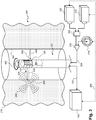
- Fig. 3 is a diagrammatic, perspective view of a medical mapping system 200 as well as a vascular pathway 104 and surrounding tissue 210.
- the medical mapping system 200 includes a measurement apparatus 102 disposed within the vascular pathway 104.
- the measurement apparatus 102 may be similar to the measurement apparatus 102 depicted in Figs. 1A-1D .
- the measurement apparatus 102 is connected to and moved through the vascular pathway 104 by a pullback device 138 such as that depicted in Figs. 1A and IB.
- a sensor array 128 may be disposed around the measurement apparatus 102.
- the sensor array 128 may be any of those depicted in Figs. 2A-2E .
- the sensor array 128 includes a plurality of ultrasound transducers which emit ultrasound signals 402 radially toward a section of the wall of the vascular pathway 104.
- the ultrasound signals 402 are reflected off the wall of the vascular pathway 104 and travel back toward the measurement apparatus 102 as ultrasound echo signals 404.
- These ultrasound echo signals 404 may be received by ultrasound transducers on the sensor array 128.
- a communication system 250 controls the transducers of the sensor array 128 to emit ultrasound signals 402 and receive ultrasound echo signals 404.
- the medical sensing system 100 is operable to map the vascular pathway 104 by mapping sections of the pathway wall as the measurement apparatus 102 is advanced through the vascular pathway 104 in direction 400.
- the sensor array 128 may be configured to rotate around a longitudinal axis of the measurement apparatus 102.
- a top section of the measurement apparatus 102 with the sensor array 128 is rotated in direction 400.
- the speed, axis, and direction of the rotation may vary throughout a medical procedure.
- the direction of rotation may be changed several times to allow the measurement apparatus to image an area several times or obtain additional diagnostic data on an area of interest.
- sections of the measurement apparatus 102 are disposed within a sheath 124 such as that depicted in Fig. IB in order to protect the measurement apparatus 102 and/or vascular pathway 104.
- some of the sensors of the sensor array 128 are rotatable around an axis of the measurement apparatus 128 while other sensors are not rotated.
- an optical element 260 such as that shown emitting the first and second sets of optical pulses 230, 252 may be rotated while a solid-state portion of the measurement apparatus remains relatively stationary. In some cases, different layers of the measurement apparatus 128 are rotated while others remain stationary.
- an operator may move the measurement apparatus 102 through the vascular pathway 104 during the process of mapping a vascular pathway 104.
- the sensor array 128 is configured to map the vascular pathway 104 independently with different modalities.
- the vascular pathway may be mapped by an ultrasound procedure independently of procedures using photoacoustic or OCT modalities.
- the sensor array 128 is operable to map with different combinations of modalities depending on a desired outcome of a procedure.
- a first optical emitter 220 and a second optical emitter 222 are also shown in Fig. 3 .
- the first optical emitter 220 and second optical emitter 222 are laser sources that are configured to emit short laser pulses toward an area of interest within the tissue 210 of the patient.
- the area of interest includes part of a vascular pathway 104 as well as adjacent tissue.
- the first and second optical emitters 220, 222 are disposed externally and optical pulses from the optical emitters 220, 222 are transmitted through a route to the measurement apparatus 102.
- one or more optical emitters may be placed within the vascular pathway.
- an optical emitter or an optical element 260 may be placed directly on the measurement apparatus 102 and may form part of the sensor array 128.
- the first optical emitter 220 may be configured to emit a first set of optical pulses 230 which travel on a route to the measurement apparatus 102 and ultimately are focused on a focus point 242 within the region of interest.
- the first set of optical pulses 230 may interact with the tissue 210 at the focus point 242, generating a series of photoacoustic waves 240 that propagate through the tissue 210 and the vascular pathway 104.
- the photoacoustic waves 240 may be received by sensors in the sensor array 128.
- the sensor array 128 is disposed on the measurement apparatus 102. In other embodiments, the sensor array 128 is disposed on a separate device in contact with the measurement apparatus.
- the sensor array 128 may be configured to send and receive signals to map the vascular pathway.
- the first and second sets of optical pulses 230, 252 are routed through one or more optical fibers disposed between the measurement apparatus and the first and second optical emitters 220, 222.
- optical fibers pass between the first and second optical emitters 220, 222 and a junction 224, between the junction 224 and a switch 226, between the switch 226 and a photo detector 228, and between the switch 226 and a measurement apparatus.
- other optical components including lenses, mirrors, and other reflectors form various sections of the route through which the first and second sets of optical pulses 230, 252 travel.
- the second optical emitter 222 may be configured as an OCT emitter.
- the second optical emitter 222 may emit a second set of optical pulses 252 which travel on a route to the measurement apparatus 102 and ultimately are emitted into the region of interest.
- the second set of optical pulses 252 may interact with tissue 210, and a set of scattered or reflected pulses 254 may travel back toward the measurement apparatus 102. In some cases, this set of reflected pulses 254 is measured and compared to the second set of optical pulses 252, allowing for the mapping of the region of interest.
- the second optical emitter 222 is configured with a similar functionality to the first optical emitter 220, and may emit sets of optical pulses that create photoacoustic waves that are received by the system to map a region of interest. This two-emitter approach may allow the medical mapping system 200 to achieve higher frequency of measurements, varying penetration depths, and/or improved contrast of imaging.
- the function of the second optical emitter 222 may be changed from a photoacoustic function to an OCT function depending on the desired outcome of the procedure. For example, the medical mapping system 200 may first be used to conduct a preliminary mapping procedure with the first optical emitter 220 having a photoacoustic function and the second optical emitter 222 having an OCT function.
- Tissue identified by the preliminary mapping procedure as a trouble area may be re-mapped at different depths and at higher resolution with both the first optical emitter 220 and the second optical emitter 222 having a photoacoustic function.
- the first and second optical emitters 220, 222 are combined into a single unit.
- the optical emitters 220, 222 may share a power source and may be operated simultaneously or independently.
- optical pulses emitted by the first and second optical emitters 220, 222 pass through a junction 224.
- This junction 224 may be adjustable and in some cases may be used to shorten or lengthen the route of the first and second sets of laser pulses 230, 252.
- the junction may be controllable by a communication system 250, a processing engine 134, a PIM 114, or a console 116, such as those depicted in Fig. 1 .
- the junction 224 is a motorized reflector.
- the junction 224 may also be included with the first and second optical emitters 220, 222 in a single housing.
- the sets of optical pulses 230, 252 emitted by the first and second optical emitters 220, 222 may also pass through a switch 226.
- the switch 226 may include one or more optical fibers, one or more reflectors, one or more lenses, and/or other optical devices.
- the switch 226 may be used to route the optical pulses in different directions. For example, optical pulses traveling from the first or second optical emitters 220, 222 may be routed to a photo detector 228 by the switch. This may allow for the analysis of reflected or deflected pulses, as in OCT imaging and/or mapping procedures.
- the switch 226 is controllable by a communication system 250, a processing engine 134, a PIM 114, or a console 116, such as those depicted in Fig. 1 .
- the first and second optical emitters 220, 222 are in communication with a communication system 250 via connection 236.
- the communication system 250 is the processing engine 134, the PIM 114, or the console 116 of Fig. 1A .
- the communication system 250 may also be connected to the measurement apparatus 102 via connection 234.
- the measurement apparatus 102 may be in direct communication with the optical emitter 220 via connection 232.
- connections 232, 234, and 236 are cables operable to transmit electronic or optical signals.
- connection 232 may be a microcable
- connection 234 may be an optical fiber
- connection 236 may be a wireless connection such as a Bluetooth or WiFi connection.
- the optical emitter 220 may include a wireless signal receiver. Connection 234 may also operate to power the measurement apparatus 102 including the sensor array 128.
- a communication system 250 may coordinate the operation of various elements, such as the first and second optical emitters 220, 222, junction 224, switch 226, photo detector 228, sensor array 128, and measurement apparatus 102. For example, several connections 232, 234, 236 may allow communication between the various elements.
- the communication system 250 includes one or more of the processing engine 134, the PIM 114, or the console 116 of Fig. 1A .
- the communication system 250 may coordinate the operation of the first and second optical emitters 220, 222 and the sensors of the sensor array 128 by sending signals to synchronize the emission of optical pulses 230, 252 and the reception of photoacoustic signals by the sensor array 128.
- the communication system 250 coordinates the operation of different sensor types on the sensor array 128.
- the communication system 250 may switch between ultrasound, optical, and photoacoustic functions on the sensor array 128.
- the operation of only one type of sensor at a time may filter out noise and yield more accurate mapping of the vascular pathway.
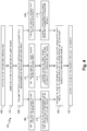
- Fig. 4 is a flow chart showing a method 400 of mapping an area of interest using photoacoustic, ultrasound, and OCT modalities. It is understood that additional steps can be provided before, during, and after the steps of method 400, and that some of the steps described can be replaced or eliminated for other examples of the method. In particular, steps 408, 410, 412, 414, 416, and 418 may be performed simultaneously or in various sequences as discussed below.
- the method 400 can include activating a first and a second laser source.
- These laser sources may be the first and second optical emitters 220, 222 depicted in Fig. 3 .
- the first and second laser sources are disposed externally and are in communication with a measurement apparatus.
- the measurement device is the measurement apparatus 102 depicted in Figs. 1A, 1B , 1C, 1D , 2A-2E , and 3 .
- the first and second laser sources may transmit laser pulses through a communication device, such as an optical fiber, to the measurement apparatus.
- the first and second laser sources are disposed on or within the measurement apparatus.
- the first and second laser sources may be included on a sensor array disposed on or within the measurement apparatus.
- the sensor array is the sensor array 128 depicted in Figs. 1A, 1B , 1C , ID, and 2A-2E.
- the sensor array may include one or more sensors and emitters including IVUS transducers, IVUS emitters, OCT transducers, photoacoustic transceivers, and optical emitters.
- the two or more transducer elements may be arranged in any of the examples depicted in Figs.
- the first and second laser sources are activated by a communication system by means of an electronic or optical signal. This signal may be sent wirelessly, and the first and second laser sources may be equipped with a wireless signal receiver.
- the method 400 can include generating a first and second set of laser pulses.
- the first and second sets of laser pulses are generated simultaneously.
- the generation of the first and second sets of laser pulses occurs at different times. This may allow the laser pulses to function with different modalities without causing interference between the pulses.
- the first set of laser pulses may be configured to produce photoacoustic waves, while the second set of laser pulses may be configured to conduct OCT imaging and/or mapping.
- the method 400 can include transmitting the first and second sets of laser pulses along a route to a measurement apparatus and a sensor array.
- the sensor array is a solid-state array or a phased array that does not rotate as it travels through the vascular pathway 104.
- the sensor array is a rotational array.
- the sensor array is disposed on a revolving portion of the measurement device.
- the sensor array is disposed circumferentially around the measurement device. The sensor array may be disposed on the measurement apparatus or alternatively, be disposed on a separate device that is connected to the measurement apparatus.
- the first and second sets of laser pulses may travel across one or more optical devices to the measurement apparatus, including optical fibers, reflectors, mirrors, etc. In some cases, the first and second sets of laser pulses travel across one or more junctions and switches. This may allow an operator to control the path of the first and second sets of laser pulses.
- the method 400 can include emitting the first set of laser pulses from the sensor array.
- the first set of laser pulses is emitted from an optical component on the sensor array, such as an optical wire or port.
- the first set of laser pulses may be focused on a tissue in a region of interest.
- the region of interest includes a portion of tissue including a portion of at least one vascular pathway 104, and the measurement device may be disposed within the vascular pathway 104.
- the region of interest may be chosen based on a suspected or diagnosed problem in the tissue, or based on the proximity of a region of tissue to problems within a vascular pathway 104. In other embodiments, the region of interest is part of a more general mapping plan.
- a mapping plan for a section of a vascular pathway 104 may involve the mapping of tissue surrounding the vascular pathway 104 along its length.
- the laser pulse is emitted outwards from a measurement device that is placed within a vascular pathway.
- the first set of laser pulses may interact with the tissue, creating a set of sound waves that travels through the tissue and the vascular pathway 104.
- the method 400 can include receiving sound waves generated by the interaction of the first set of laser pulses and tissue.
- the sensor array includes a photoacoustic sensor, which may also function with the traditional IVUS function and receive ultrasound waves.
- the photoacoustic sensor may be an ultrasound transducer.
- the photoacoustic sensor is configured to receive only photoacoustic waves.
- the sensor elements, including a photoacoustic sensor are controlled by a communication system similar to communication system 250 of Fig. 3 .
- a processing engine 134 or a PIM 114 controls the operation of the sensor of the sensor array 128. Signals may be sent from processing engine 134 or the PIM 114 to sensors in the sensor array, via connector 234, causing the sensors to receive diagnostic information.
- the method 400 can include emitting the second set of laser pulses from the sensor array.
- the second set of laser pulses may be focused on a region of tissue. A portion of the laser pulses may be scattered or reflected by interaction optical pulses with the tissue, and some of these reflected pulses may travel back toward the sensor array.
- the method 400 can include receiving the reflected laser pulses generated by the interaction of the second set of laser pulses and the tissue.
- the pulses are received by one or more optical receivers on the sensor array.
- these optical receivers may receive the reflected laser pulses and send data on the reflected pulses to be compared with the second set of optical pulses. This may allow parts of the tissue to be imaged, for example, in an OCT modality.
- the method 400 can include transmitting ultrasound signals into the vascular pathway 104.
- the sensor array of step 406 includes one or more ultrasound transducers which may emit ultrasound signals toward the walls of the vascular pathway 104.
- the transmitted ultrasound signals may be deflected off the walls of the vascular pathway 104 and propagate through the vascular pathway 104 as ultrasound echo signals.
- the method 400 can include receiving the ultrasound echo signals from the transmitted ultrasound signals.
- an ultrasound transducer receives the ultrasound echo signals.
- the ultrasound transducer of steps 410, 416, and 418 may be combined in a single element. In this case, the transducer may be able to receive both sound waves and ultrasound signals. In other embodiments, the transducer elements are separate elements.
- steps 404, 406, 408, 410, 412, 414, 416, and 418 may be coordinated in various combinations and orders in the method 400.
- the order of steps of method 400 may be determined based on the desired outcome of a medical procedure. For example, transmission of ultrasound signals and reception of ultrasound echo signals can occur at regular intervals throughout the method 400, while reception of photoacoustic waves and reflected laser pulses may occur sporadically. This may be the case in a medical procedure to map a vascular pathway 104 and spot-check trouble areas of tissue surrounding sections of the vascular pathway 104.
- steps 408, 410, 412, 414, 416, and 418 are performed successively.
- each of steps 408, 410, and 416 may be performed individually before proceeding to the next step to avoid signal noise and allow for adequate signal processing. This may be the case when method 400 in used conjunction with a system where a photoacoustic sensor, optical transducer, and ultrasound transducer are each included in the sensor array. Furthermore, the steps of method 400 may be interleaved in various orders.
- the measurement apparatus and sensor array may be moved during the operation of steps 406, 408, 410, 412, 414, 416, and 418.
- method 400 can include rotating the sensor array about a longitudinal axis of the measurement device.
- the sensor array is rotated throughout steps 408, 410, 412, 414, 416 and 418, as in the case where the measurement device continually maps a vascular pathway as is it pulled through the vascular pathway.
- the sensor array is kept motionless during various steps.
- the rotation of the sensor array may be accomplished through the use of a drive member connected to the measurement device. In some embodiments, such as the example of Fig.
- parts of the sensor array are rotated around a longitudinal axis of the measurement device while other parts of the sensor array are not rotated.
- the rotation of the sensor array can vary in direction and rate of rotation.
- the sensor array may be rotated 180° in a counter-clockwise direction and/or rotated in an 180° counter-clockwise direction. Rotations in each direction of 90°, 270°, 360°, and other angles are also contemplated.
- the method 400 can include producing an image of the region of interest, including the vascular pathway 104 and surrounding tissue, based on the sound waves, reflected laser pulses, and the ultrasound echo signals.
- a processing engine 134 in communication with the sensor array produces the image of the region of interest. This image can include both two-dimensional and three-dimensional images based on the received sensor data. In some cases, the image includes a number of two-dimensional cross sections of the vascular pathway 104 and surrounding tissue.
- the method 400 can include outputting the image of the region of interest to a display.
- this display is the display 118 depicted in Fig. 1A .
- the display 118 can include a computer monitor, a screen on a patient interface module (PIM) 114 or console 116, or other suitable device for receiving and displaying images.
- PIM patient interface module
- the method 400 repeats after step 422, such that method flow goes back to step 404 and begins again. Iteration of the method 400 may be utilized to map a vascular pathway and surrounding tissue.
Description
- The present disclosure relates generally to imaging and mapping vascular pathways and surrounding tissue with photoacoustic and ultrasound modalities.
- Innovations in diagnosing and verifying the level of success of treatment of disease have migrated from external imaging processes to internal diagnostic processes. In particular, diagnostic equipment and processes have been developed for diagnosing vasculature blockages and other vasculature disease by means of ultra-miniature sensors placed upon the distal end of a flexible measurement apparatus such as a catheter, or a guide wire used for catheterization procedures. For example, known medical sensing techniques include angiography, intravascular ultrasound (IVUS), forward looking IVUS (FL-IVUS), fractional flow reserve (FFR) determination, a coronary flow reserve (CFR) determination, optical coherence tomography (OCT), trans-esophageal echocardiography, and image-guided therapy.
- For example, intravascular ultrasound (IVUS) imaging is widely used in interventional cardiology as a diagnostic tool for assessing a diseased vessel, such as an artery, within the human body to determine the need for treatment, to guide the intervention, and/or to assess its effectiveness. There are two general types of IVUS devices in use today: rotational and solid-state (also known as synthetic aperture phased array). For a typical rotational IVUS device, a single ultrasound transducer element is located at the tip of a flexible driveshaft that spins inside a plastic sheath inserted into the vessel of interest. In side-looking rotational devices, the transducer element is oriented such that the ultrasound beam propagates generally perpendicular to the longitudinal axis of the device. In forward-looking rotational devices, the transducer element is pitched towards the distal tip so that the ultrasound beam propagates more towards the tip (in some devices, being emitted parallel to the longitudinal centerline). The fluid-filled sheath protects the vessel tissue from the spinning transducer and driveshaft while permitting ultrasound signals to propagate from the transducer into the tissue and back. As the driveshaft rotates, the transducer is periodically excited with a high voltage pulse to emit a short burst of ultrasound. The same transducer then listens for the returning echoes reflected from various tissue structures. The IVUS medical sensing system may assemble a two dimensional display of the tissue, vessel, heart structure, etc. from a sequence of pulse/acquisition cycles occurring during a single revolution of the transducer. In order to image a length of a vessel, the transducer element may be drawn through the vessel as it spins.
- In contrast, solid-state IVUS devices utilize a scanner assembly that includes an array of ultrasound transducers connected to a set of transducer controllers. In side-looking and some forward-looking IVUS devices, the transducers are distributed around the circumference of the device. In other forward-looking IVUS devices, the transducers are a linear array arranged at the distal tip and pitched so that the ultrasound beam propagates closer to parallel with the longitudinal centerline. The transducer controllers select transducer sets for transmitting an ultrasound pulse and for receiving the echo signal. By stepping through a sequence of transmit-receive sets, the solid-state IVUS system can synthesize the effect of a mechanically scanned transducer element but without moving parts. Since there is no rotating mechanical element, the sensor array can be placed in direct contact with the blood and vessel tissue with minimal risk of vessel trauma. Furthermore, because there is no rotating element, the interface is simplified. The solid-state scanner can be wired directly to the medical sensing system with a simple electrical cable and a standard detachable electrical connector. While the transducers of the scanner assembly do not spin, operation is similar to that of a rotational system in that, in order to image a length of a vessel, the scanner assembly is drawn through the vessel while stepping through the transmit-receive sets to produce a series of radial scans.
- Rotational and solid-state state IVUS are merely some examples of imaging modalities that sample a narrow region of the environment and assemble a two- or three-dimensional image from the results. Other examples include optical coherence tomography (OCT), which has been used in conjunction with ultrasound systems. One of the key challenges using these modalities with in a vascular pathway is that they are limited in gathering data on anatomy beyond the vessel walls. Although OCT imaging may yield higher resolution than IVUS imaging, OCT has particularly limited penetration depth and may take more time to image a region of tissue.
- Another recent biomedical imaging modality is photoacoustic imaging. Photoacoustic imaging devices deliver a short laser pulse into tissue and monitor the resulting acoustic output from the tissue. Due to varying optical absorption throughout the tissue, pulse energy from the laser pulse causes differential heating in the tissue. This heating and associated expansion leads to the creation of sound waves corresponding to the optical absorption of the tissue. These sound waves can be detected and an image of the tissue can be generated through analysis of the sound waves and associated vascular structures can be identified, as described in
U.S. Patent Publication 2013/0046167 titled "SYSTEMS AND METHODS FOR IDENTIFYING VASCULAR BORDERS". -
US 2011/098572 A1 relates to an imaging probe for a biological sample that includes an OCT probe and an ultrasound probe combined with the OCT probe in an integral probe package capable of providing by a single scanning operation images from the OCT probe and ultrasound probe to simultaneously provide integrated optical coherence tomography (OCT) and ultrasound imaging of the same biological sample. -
WO 2015/054243 A1 relates to a multimodality imaging system including ultrasound, optical coherence tomography (OCT), photoacoustic (PA) imaging, florescence imaging and endoscopic catheter for imaging inside the gastrointestinal tract with real-time automatic image co-registration capability, including: an ultrasound subsystem for imaging; an optical coherence tomography (OCT) subsystem for imaging, a PA microscopy or tomography subsystem for imaging and a florescence imaging subsystem for imaging. - Accordingly, for these reasons and others, the need exists for improved systems and techniques that allow for the mapping of vascular pathways and surrounding tissue.
- The object of the present invention is solved by the subject-matter of the independent claim; further embodiments are incorporated in the dependent claims. Embodiments of the present disclosure provide a mapping system that combines photoacoustic and IVUS imaging system on a measurement apparatus configured to be placed in a vascular pathway. The system may allow for combinations of three mapping modalities: ultrasound, photoacoustic, and OCT. The sensor array may be rotatable around an axis of the measurement apparatus and allow the system to map vascular pathways and surrounding tissue.
- Additional aspects, features, and advantages of the present disclosure will become apparent from the following detailed description.
- Illustrative embodiments of the present disclosure will be described with reference to the accompanying drawings, of which:
-
Fig 1A is a diagrammatic schematic view of a medical sensing system according to some embodiments of the present disclosure. - Fig IB is a diagrammatic schematic view of a medical sensing system according to some embodiments of the present disclosure.
-
Fig 1C is a diagrammatic schematic view of a medical sensing system with an exemplary sensor array according to some embodiments of the present disclosure. - Fig ID is a diagrammatic schematic view of a medical sensing system with another exemplary sensor array according to some embodiments of the present disclosure.
-
Fig 2A is a diagrammatic schematic view of a medical sensing system with a sensor array according to an embodiment of the present disclosure. -
Fig 2B is a diagrammatic schematic view of a medical sensing system with a sensor array according to another embodiment of the present disclosure. -
Fig 2C is a diagrammatic schematic view of a medical sensing system with a sensor array according to another embodiment of the present disclosure. -
Fig 2D is a diagrammatic schematic view of a medical sensing system with a sensor array according to another embodiment of the present disclosure. -
Fig 2E is a diagrammatic schematic view of a medical sensing system with a sensor array according to another embodiment of the present disclosure. -
Fig. 3 is a diagrammatic, perspective view of a vascular pathway and surrounding tissue with an instrument positioned within the pathway according to an embodiment of the present disclosure. -
Fig. 4 is a flow diagram of a method for mapping a vascular pathway with a sensor array according to an example provided for better understanding. - For the purposes of promoting an understanding of the principles of the present disclosure, reference will now be made to the embodiments illustrated in the drawings, and specific language will be used to describe the same. It is nevertheless understood that no limitation to the scope of the disclosure is intended. Any alterations and further modifications to the described devices and systems, and any further application of the principles of the present disclosure are fully contemplated and included within the present disclosure as would normally occur to one skilled in the art to which the disclosure relates. For example, while the intravascular sensing system is described in terms of cardiovascular imaging, it is understood that it is not intended to be limited to this application. The system is equally well suited to any application requiring imaging within a confined cavity. In particular, it is fully contemplated that the features, components, and/or steps described with respect to one embodiment may be combined with the features, components, and/or steps described with respect to other embodiments of the present disclosure. For the sake of brevity, however, the numerous iterations of these combinations will not be described separately.
-
Fig. 1A is a diagrammatic schematic view of amedical sensing system 100 according to some embodiments of the present disclosure. Themedical sensing system 100 includes a measurement apparatus 102 (such as a catheter, guide wire, or guide catheter). As used herein, "measurement apparatus" or "flexible measurement apparatus" includes at least any thin, long, flexible structure that can be inserted into the vasculature of a patient. While the illustrated embodiments of the "measurement apparatus" of the present disclosure have a cylindrical profile with a circular cross-sectional profile that defines an outer diameter of theflexible measurement apparatus 102, in other instances, all or a portion of theflexible measurement apparatus 102 may have other geometric cross-sectional profiles (e.g., oval, rectangular, square, elliptical, etc.) or non-geometric cross-sectional profiles.Flexible measurement apparatus 102 may include, for example, guide wires, catheters, and guide catheters. In that regard, a catheter may or may not include a lumen extending along all or a portion of its length for receiving and/or guiding other instruments. If the catheter includes a lumen, the lumen may be centered or offset with respect to the cross-sectional profile of the device. - The
medical sensing system 100 may be utilized in a variety of applications and can be used to assess vessels and structures within a living body. To do so, themeasurement apparatus 102 is advanced into avessel 104.Vessel 104 represents fluid filled or surrounded structures, both natural and man-made, within a living body that may be imaged and can include for example, but without limitation, structures such as: organs including the liver, heart, kidneys, as well as valves within the blood or other systems of the body. In addition to imaging natural structures, the images may also include man-made structures such as, but without limitation, heart valves, stents, shunts, filters and other devices positioned within the body. Themeasurement apparatus 102 includes one ormore sensors 106 disposed along the length of theapparatus 102 to collect diagnostic data regarding thevessel 104. In various embodiments, the one ormore sensors 106 correspond to sensing modalities such as IVUS imaging, pressure, flow, OCT imaging, transesophageal echocardiography, temperature, other suitable modalities, and/or combinations thereof. - In the exemplary embodiment of
Fig. 1A , themeasurement apparatus 102 includes a solid-state IVUS device, and thesensors 106 include one or more IVUS ultrasound transducers and/or photoacoustic transducers and associated control. As used herein, a "photoacoustic transducer" includes at least a sensor configured to detect photoacoustic waves generated as a result of the interaction of optical pulses with tissue. In one embodiment, a photoacoustic transducer utilizes the same ultrasound detection mechanism as an IVUS ultrasound transducer. In some implementations, a single transducer can serve as both an IVUS transducer and a photoacoustic transducer. In another embodiment, a photoacoustic transducer uses a dedicated photoacoustic wave detection mechanism distinct from that of an IVUS ultrasound transducer. The system ofFig. 1A may include aspects of phased-array IVUS devices, systems, and methods associated with the Eagle Eye® Platinum catheter available from Volcano Corporation as well as those described inU.S. Patent No. 7,846,101 and/orU.S. Patent Application No. 14/812,792, filed July 29, 2015 US 2016/0029999 A1 ). - In another embodiment, a photoacoustic transducer uses a dedicated photoacoustic wave detection mechanism distinct from that of an IVUS ultrasound transceiver. As used herein, "optical emitter" can include an optical source such a laser emitter, as well as an optical device used to transmit optical signals, such as lenses, fibers, and optical ports. As used herein, "optical transceiver" can be any device used to receive and measure optical signals, such as photo detectors and charge-coupled devices (CCD).
- The
sensors 106 may be arranged around the circumference of themeasurement apparatus 102 and positioned to emit ultrasound energy radially 110 in order to obtain a cross-sectional representation of thevessel 104 and the surrounding anatomy. When thesensors 106 are positioned near the area to be imaged, the control circuitry selects one or more IVUS transducers to transmit an ultrasound pulse that is reflected by thevessel 104 and the surrounding structures. The control circuitry also selects one or more transducers to receive the ultrasound echo signal. By stepping through sequences of transmit-receive sets, themedical sensing system 100 system can synthesize the effect of a mechanically scanned transducer element without moving parts. - In one embodiment, the
sensors 106 are disposed circumferentially around a distal portion of themeasurement apparatus 102. In another embodiment, thesensors 106 are contained within the body of themeasurement apparatus 102. In other embodiments, thesensors 106 are disposed radially across themeasurement apparatus 102, on a movable drive member connected to themeasurement apparatus 102, or on one or more planar arrays connected to themeasurement apparatus 102. More examples of sensor placement are shown inFigs. 1C , ID, and 2A-2E. - In some embodiments, the
processing engine 134, which may be included in theconsole 116, combines the imaging data acquired from both the IVUS and photoacoustic modalities into a single visualization. This use of both IVUS and photoacoustic modalities may provide a number of advantages over traditional systems using a single modality. First, the addition of photoacoustic sensors may allow for higher resolution mapping than traditional IVUS methods alone. Second, the combination of IVUS and photoacoustic modalities may allow for faster imaging speeds than OCT imaging or other methods. Third, the combination may allow for two-dimensional and/or three-dimensional imaging of the tissue surrounding vascular pathways. Fourth, the use of photoacoustic imaging may expand the diagnostic scope of an IVUS mapping procedure by including more of the surrounding tissue. In particular, the combined IVUS and photoacoustic mapping can allow for detection of certain types of cancers, tissue damage, and the mapping of multiple vascular pathways without sacrificing the dependability of ultrasound in detecting plaques, stenosis, and other forms of vascular diseases. Fifth, combining these two modalities may allow substantial costs savings because existing IVUS systems may be adapted to mapping systems using both modalities. Sixth, due to the interaction of optical pulses with tissue and the omni-directional emission of photoacoustic waves from the tissue, an optical pulse need not be emitted along the same axis as the transducer. This allows for more flexibility in carrying out combined photoacoustic and IVUS procedures, and may allow for precise mapping procedures even along deep or convoluted vascular pathways. Seventh, the mapping capabilities of the present disclosure may be integrated with some forms of laser therapy. For example, diagnosis of diseases in tissue may be accomplished using the optical emitter in diagnostic mode. After a diagnosis, the optical emitter can be switched to a treatment mode. In this regard, the map of the vasculature and surrounding tissue may be used to guide the application of the treatment. After the optical treatment is finished, the optical emitter can be switched back to diagnostic mode to confirm treatment of the diseased portion of tissue. - Sensor data may be transmitted via a
cable 112 to a Patient Interface Module (PIM) 114 and to console 116, as well as to theprocessing engine 134 which may be disposed within theconsole 116. Data from the one ormore sensors 106 may be received by aprocessing engine 134 of theconsole 116. In other embodiments, theprocessing engine 134 is physically separated from themeasurement apparatus 102 but in communication with the measurement apparatus (e.g., via wireless communications). In some embodiments, theprocessing engine 134 is configured to control thesensors 106. Precise timing of the transmission and reception of signals may be used to mapvascular pathways 104 in procedures using both IVUS and photoacoustic modalities. In particular, some procedures may involve the activation ofsensors 106 to alternately transmit and receive signals. In systems using one or more IVUS transducers that are configured to receive both photoacoustic and ultrasound signals, theprocessing engine 134 may be configured to control the state (e.g., send/receive) of one or more transducers during the mapping of the vascular pathway and surrounding tissue. - Moreover, in some embodiments, the
processing engine 134,PIM 114, andconsole 116 are collocated and/or part of the same system, unit, chassis, or module. Together theprocessing engine 134,PIM 114, and/orconsole 116 assemble, process, and render the sensor data for display as an image on adisplay 118. For example, in various embodiments, theprocessing engine 134,PIM 114, and/or theconsole 116 generates control signals to configure thesensor 106, generates signals to activate thesensor 106, performs amplification, filtering, and/or aggregating of sensor data, and formats the sensor data as an image for display. The allocation of these tasks and others can be distributed in various ways between theprocessing engine 134,PIM 114, and theconsole 116. - Sill referring to
Fig. 1A , apullback device 138 may be connected to themeasurement apparatus 102. In some embodiments, thepullback device 138 is configured to pull ameasurement apparatus 102 through avascular pathway 104. Thepullback device 138 may be configured to pull the measurement apparatus at one or more fixed velocities and/or fixed distances. In other instances, thepullback device 138 may be configured to pull the measurement apparatus at variable speeds and/or variable distances. Thepullback device 138 may be selectively connected to themeasurement apparatus 102 by mechanical connections such as male/female plug interactions, mechanical couplings, fasteners, and/or combinations thereof. Further, in some instances thepullback device 138 may be mechanically coupled and/or integrated with thePIM 114. In such instances, connection of themeasurement apparatus 102 to thePIM 114 can couple thepullback device 138 to themeasurement apparatus 102. Thepullback device 138 may be slid across a cable, track, wire, or ribbon. In some embodiments, thepullback device 138 is in communication with one or more of aprocessing engine 134, aPIM 114, or aconsole 116. Furthermore, thepullback device 138 may be controlled by signals sent through aprocessing engine 134, aPIM 114, or aconsole 116. Thepullback device 138 may also be placed in communication with another motivation device such as an actuator to drive an external optical emitter. In some embodiments, an actuator is synched with thepullback device 138 to synchronously move an external optical emitter and ameasurement apparatus 102. - In addition to
various sensors 106, themeasurement apparatus 102 may include a guidewire exit port 120 as shown inFig. 1A . The guidewire exit port 120 allows aguide wire 122 to be inserted towards the distal end in order to direct themember 102 through a vascular structure (i.e., the vessel) 104. Accordingly, in some instances themeasurement apparatus 102 is a rapid-exchange catheter. Additionally or in the alternative, themeasurement apparatus 102 can be advanced through thevessel 104 inside aguide catheter 124. In an embodiment, themeasurement apparatus 102 includes aninflatable balloon portion 126 near the distal tip. Theballoon portion 126 is open to a lumen that travels along the length of the IVUS device and ends in an inflation port (not shown). Theballoon 126 may be selectively inflated and deflated via the inflation port. In other embodiments, themeasurement apparatus 102 does not includeballoon portion 126. - Fig. IB is a schematic view of a system that includes an
alternative measurement apparatus 102 according to some embodiments of the present disclosure. Themeasurement apparatus 102 of Fig. IB is typical of a rotational device such as a rotational IVUS ultrasound system and the one ormore sensors 106 include one or more IVUS transducers arranged to emit ultrasound energy in aradial direction 110, as well as one or more photoacoustic transducers. Again, a single transducer may serve as both an IVUS transducer and a photoacoustic transducer. In such an embodiment, the one ormore sensors 106 may be mechanically rotated around a longitudinal axis of themeasurement apparatus 102 to obtain a cross-sectional representation of thevessel 104. The system of Fig. IB may include aspects of rotational IVUS devices, systems, and methods associated with the Revolution® catheter available from Volcano Corporation as well as those described inU.S. Nos. 5,243,988 ,5,546,948 , and8,104,479 and/orU.S. Patent Application No. 14/837,829, filed August 27, 2015 US 2016/0058414 A1 ). - In some embodiments,
sensors 106 include an OCT transceiver or an optical emitter configured to emit optical pulses from within the vascular pathway. An optical emitter may be configured to rotate around themeasurement apparatus 102. Other embodiments incorporate other combinations of sensors. No particular sensor or combination of sensors is required for any particular embodiment. -
Figs. 1C and 1D show further examples of ameasurement apparatus 102 as contemplated by the present disclosure. In particular, the composition and placement ofsensors 106 may be varied on themeasurement apparatus 102. For example,Fig. 1C shows ameasurement apparatus 102 which includes solid-state sensors 106a (also known as phased array sensors) and arotational sensor 106b. In the example ofFig. 1C , therotational sensor 106b is disposed on adrive member 140 that is attached to themeasurement apparatus 102.Sensors 106 may include IVUS transducers, IVUS emitters, photoacoustic transducers, and optical emitters. Therotational sensor 106b may include an optical emitter or an ultrasound transducer. In some embodiments, thedrive member 140 is attached to themeasurement apparatus 102 with a drive shaft or movable hinge. Thedrive member 140 may be configured to rotate with respect to a longitudinal axis of themeasurement apparatus 102. In some cases, the solid-state sensors 106a are attached directly to themeasurement apparatus 102 and remain relatively stationary with respect to therotating drive member 140. In some embodiments, the solid-state sensors 106a are disposed circumferentially around themeasurement apparatus 102. Therotational sensor 106b may be configured to rotate around themeasurement apparatus 102 in full 360° arcs. Alternatively or additionally, the rotational sensor is configured to rotate in arcs of 270°, 180°, 90°, or arcs of various other measurements. The direction of rotation of therotational sensor 106b may vary along the length of the vascular pathway. - Fig. ID shows a
measurement apparatus 102 that includes asensor array 128. In the example if Fig. ID, thesensor array 128 may be configured to rotate with respect to a longitudinal axis of themeasurement apparatus 102. In particular, thesensor array 128 may include sensors and emitters including IVUS transducers, IVUS emitters, photoacoustic transducers, and optical emitters. In some embodiments, thesensor array 128 includes sensors of at least two different types or modalities. For example, thesensor array 128 may include one or morerotational sensors 106a as well as sensors of afirst type 130 and sensors of asecond type 132. In the example of Fig. ID, the sensors of the first andsecond types array 128 in an alternating manner. In some embodiments (not shown), sensors of the first andsecond types array 128 in a checkerboard configuration such that individual sensors of thefirst type 130 are not adjacent to each other. Additionally, sensors of the first andsecond types array 128. Although they appear as square or rectangular in the example ofFig. 1C , sensors of the first andsecond types second types measurement apparatus 120 or they may be placed flush against each other. In some embodiments, each type of sensor may take up roughly equal proportions of the area of thearray 128 relative to the other sensor types. In other embodiments, the ratio of the surface areas of two or more sensor types on thesensor array 128 is 20% and 80%, 30% and 70%, or 40% and 60%, respectively. - In the example of Fig. ID, a
sensor array 128 is shown with sensors of two or moredifferent types measurement apparatus 102. In some embodiments, rows of sensors placed in a staggered formation such that the ends of individual rows are not co-terminus. In some embodiments, rows of sensors are placed adjacent to each other with no space in between. Alternatively, rows of sensors are spaced across themeasurement apparatus 102 with space therebetween. In some cases, 2, 3, 4, or 5 rows of alternating sensors are disposed on themeasurement apparatus 102. As discussed above, thearray 128 may be configured to rotate around an axis of themeasurement apparatus 102. - As the
measurement apparatus 102 is moved along avascular pathway 104, therotational sensors 106b and the sensors of the first andsecond types measurement apparatus 102 is moved at a slow speed so that sensors on opposite sides of thesensor array 128 are able to map the entirevascular pathway 104 individually, creating a multimodal map of thevascular pathway 104. - The
sensor array 128 may also be disposed on a separate instrument in contact with themeasurement apparatus 102, as shown inFig. 1C . For example, thesensor array 128 may be disposed circumferentially on adrive member 140 which is in contact with themeasurement apparatus 102 and revolves about the longitudinal axis of themeasurement apparatus 102. -
Figs. 2A-2E show examples of asensor array 128 that may be used in conjunction with themeasurement apparatus 102 according to some embodiments of the present disclosure. Only a portion of themeasurement apparatus 102 is shown inFigs. 2A-2E . In some embodiments, other components are disposed distal or proximal to thesensor array 128 that are not portrayed inFigs. 2A-2E . In some embodiments, asensor array 128 is placed in a similar position as thesensors 106 ofFigs. 1A and IB. Thesensor array 128 may include one or more sensors and emitters including ultrasound transducers, photoacoustic transceivers, optical emitters, and/or optical receivers. In the example ofFigs. 2A-2D , thesensor array 128 is disposed around the circumference of themeasurement apparatus 102, while inFig. 2E , parts of thesensor array 128 are disposed within the body of themeasurement apparatus 102. Although not shown,sensor arrays 128 may also disposed on a distal end of the measurement apparatus or on a drive member or other device separate from the measurement apparatus. - In the example of
Fig. 2A , sensors of afirst type 130 and sensors of asecond type 132 are included in asensor array 128. The sensors of the first andsecond type measurement apparatus 102. In some embodiments, rows of sensors placed in a staggered formation such that the ends of individual rows are not co-terminus. In some embodiments, rows of sensors are placed adjacent to each other with no space in between. Alternatively, rows of sensors are spaced across themeasurement apparatus 102 with space(s) therebetween. In some cases, 2, 3, 4, or 5 rows of alternating sensors are disposed on themeasurement apparatus 102. As discussed above, thearray 128 may be configured to rotate around an axis of themeasurement apparatus 102. - In the example of
Fig. 2B , asensor array 128 is shown with sensors of a first type and asecond type measurement apparatus 102 with space therebetween. - In the example of
Fig. 2C , the sensors of the first andsecond types array 128 in an alternating manner. In some embodiments, sensors of the first andsecond types array 128 in a checkerboard configuration such that individual sensors of thefirst type 130 are not adjacent to each other. Additionally, sensors of the first andsecond types array 128. Although they appear as square or rectangular in the example ofFig. 2C , sensors of the first andsecond types second types measurement apparatus 120 or they may be placed flush against each other. - In the example of
Fig. 2D , asensor array 128 is shown with sensors of thefirst type 130 surrounded by sensors thesecond type 132. In some embodiments, the ratio of the surface areas of the sensors of the first andsecond types sensor array 128 is 20% and 80%, 30% and 70%, or 40% and 60%, respectively. In one embodiment, sensors of the first andsecond types sensor array 128. In another embodiment, some sensors of the first andsecond types second types sensor array 128. - In the example of
Fig. 2E , asensor array 128 is shown withconcentric layers 136 of sensors. In some embodiments,layers 136 of sensors are disposed coaxially with themeasurement apparatus 102. Furthermore, sensors of the first andsecond types layers 136 in thesensor array 128. For example, asensor layer 136 comprising ultrasound transducers may lie above a layer of photoacoustic transducers, which lies above another layer of ultrasound transducers. This arrangement may allow for a morecompact measurement apparatus 102 suitable for use within a wide range of vascular passages. Otherexemplary sensor arrays 128 and combinations of sensors are contemplated besides those shown inFigs. 2A-2E . For example, asensor array 128 may combine the layers ofFig. 2E with the checkerboard layout ofFig. 2C to create a layered, alternatingsensor array 128. -
Fig. 3 is a diagrammatic, perspective view of amedical mapping system 200 as well as avascular pathway 104 and surroundingtissue 210. In some embodiments, themedical mapping system 200 includes ameasurement apparatus 102 disposed within thevascular pathway 104. Themeasurement apparatus 102 may be similar to themeasurement apparatus 102 depicted inFigs. 1A-1D . In some embodiments, themeasurement apparatus 102 is connected to and moved through thevascular pathway 104 by apullback device 138 such as that depicted inFigs. 1A and IB. Asensor array 128 may be disposed around themeasurement apparatus 102. Thesensor array 128 may be any of those depicted inFigs. 2A-2E . In some embodiments, thesensor array 128 includes a plurality of ultrasound transducers which emit ultrasound signals 402 radially toward a section of the wall of thevascular pathway 104. The ultrasound signals 402 are reflected off the wall of thevascular pathway 104 and travel back toward themeasurement apparatus 102 as ultrasound echo signals 404. These ultrasound echo signals 404 may be received by ultrasound transducers on thesensor array 128. In some cases, acommunication system 250 controls the transducers of thesensor array 128 to emit ultrasound signals 402 and receive ultrasound echo signals 404. In some embodiments, themedical sensing system 100 is operable to map thevascular pathway 104 by mapping sections of the pathway wall as themeasurement apparatus 102 is advanced through thevascular pathway 104 indirection 400. - In some embodiments, the
sensor array 128 may be configured to rotate around a longitudinal axis of themeasurement apparatus 102. In the example ofFig. 3 , a top section of themeasurement apparatus 102 with thesensor array 128 is rotated indirection 400. The speed, axis, and direction of the rotation may vary throughout a medical procedure. For example, the direction of rotation may be changed several times to allow the measurement apparatus to image an area several times or obtain additional diagnostic data on an area of interest. In some embodiments, sections of themeasurement apparatus 102 are disposed within asheath 124 such as that depicted in Fig. IB in order to protect themeasurement apparatus 102 and/orvascular pathway 104. In some embodiments, some of the sensors of thesensor array 128 are rotatable around an axis of themeasurement apparatus 128 while other sensors are not rotated. For example, anoptical element 260, such as that shown emitting the first and second sets ofoptical pulses measurement apparatus 128 are rotated while others remain stationary. - In some cases, an operator may move the
measurement apparatus 102 through thevascular pathway 104 during the process of mapping avascular pathway 104. In some cases, thesensor array 128 is configured to map thevascular pathway 104 independently with different modalities. For example, the vascular pathway may be mapped by an ultrasound procedure independently of procedures using photoacoustic or OCT modalities. In some embodiments, thesensor array 128 is operable to map with different combinations of modalities depending on a desired outcome of a procedure. - A first
optical emitter 220 and a secondoptical emitter 222 are also shown inFig. 3 . In some embodiments, the firstoptical emitter 220 and secondoptical emitter 222 are laser sources that are configured to emit short laser pulses toward an area of interest within thetissue 210 of the patient. In some embodiments, the area of interest includes part of avascular pathway 104 as well as adjacent tissue. In the example ofFig. 3 , the first and secondoptical emitters optical emitters measurement apparatus 102. However, in other embodiments, one or more optical emitters may be placed within the vascular pathway. For example, an optical emitter or anoptical element 260 may be placed directly on themeasurement apparatus 102 and may form part of thesensor array 128. - The first
optical emitter 220 may be configured to emit a first set ofoptical pulses 230 which travel on a route to themeasurement apparatus 102 and ultimately are focused on afocus point 242 within the region of interest. The first set ofoptical pulses 230 may interact with thetissue 210 at thefocus point 242, generating a series ofphotoacoustic waves 240 that propagate through thetissue 210 and thevascular pathway 104. Thephotoacoustic waves 240 may be received by sensors in thesensor array 128. In some embodiments, thesensor array 128 is disposed on themeasurement apparatus 102. In other embodiments, thesensor array 128 is disposed on a separate device in contact with the measurement apparatus. Thesensor array 128 may be configured to send and receive signals to map the vascular pathway. - In some embodiments, the first and second sets of
optical pulses optical emitters optical emitters junction 224, between thejunction 224 and aswitch 226, between theswitch 226 and aphoto detector 228, and between theswitch 226 and a measurement apparatus. Additionally, other optical components, including lenses, mirrors, and other reflectors form various sections of the route through which the first and second sets ofoptical pulses - The second
optical emitter 222 may be configured as an OCT emitter. In particular, the secondoptical emitter 222 may emit a second set ofoptical pulses 252 which travel on a route to themeasurement apparatus 102 and ultimately are emitted into the region of interest. The second set ofoptical pulses 252 may interact withtissue 210, and a set of scattered or reflectedpulses 254 may travel back toward themeasurement apparatus 102. In some cases, this set of reflectedpulses 254 is measured and compared to the second set ofoptical pulses 252, allowing for the mapping of the region of interest. In some embodiments, the secondoptical emitter 222 is configured with a similar functionality to the firstoptical emitter 220, and may emit sets of optical pulses that create photoacoustic waves that are received by the system to map a region of interest. This two-emitter approach may allow themedical mapping system 200 to achieve higher frequency of measurements, varying penetration depths, and/or improved contrast of imaging. In some embodiments, the function of the secondoptical emitter 222 may be changed from a photoacoustic function to an OCT function depending on the desired outcome of the procedure. For example, themedical mapping system 200 may first be used to conduct a preliminary mapping procedure with the firstoptical emitter 220 having a photoacoustic function and the secondoptical emitter 222 having an OCT function. Tissue identified by the preliminary mapping procedure as a trouble area may be re-mapped at different depths and at higher resolution with both the firstoptical emitter 220 and the secondoptical emitter 222 having a photoacoustic function. In some embodiments, the first and secondoptical emitters optical emitters - In some embodiments, optical pulses emitted by the first and second
optical emitters junction 224. Thisjunction 224 may be adjustable and in some cases may be used to shorten or lengthen the route of the first and second sets oflaser pulses communication system 250, aprocessing engine 134, aPIM 114, or aconsole 116, such as those depicted inFig. 1 . In some embodiments, thejunction 224 is a motorized reflector. Thejunction 224 may also be included with the first and secondoptical emitters - The sets of
optical pulses optical emitters switch 226. Theswitch 226 may include one or more optical fibers, one or more reflectors, one or more lenses, and/or other optical devices. Theswitch 226 may be used to route the optical pulses in different directions. For example, optical pulses traveling from the first or secondoptical emitters photo detector 228 by the switch. This may allow for the analysis of reflected or deflected pulses, as in OCT imaging and/or mapping procedures. In some embodiments, theswitch 226 is controllable by acommunication system 250, aprocessing engine 134, aPIM 114, or aconsole 116, such as those depicted inFig. 1 . - In the example of
Fig. 2 , the first and secondoptical emitters communication system 250 viaconnection 236. In some embodiments, thecommunication system 250 is theprocessing engine 134, thePIM 114, or theconsole 116 ofFig. 1A . Thecommunication system 250 may also be connected to themeasurement apparatus 102 viaconnection 234. Furthermore, themeasurement apparatus 102 may be in direct communication with theoptical emitter 220 viaconnection 232. In some embodiments,connections connection 232 may be a microcable,connection 234 may be an optical fiber, andconnection 236 may be a wireless connection such as a Bluetooth or WiFi connection. Additionally, theoptical emitter 220 may include a wireless signal receiver.Connection 234 may also operate to power themeasurement apparatus 102 including thesensor array 128. - A
communication system 250 may coordinate the operation of various elements, such as the first and secondoptical emitters junction 224,switch 226,photo detector 228,sensor array 128, andmeasurement apparatus 102. For example,several connections communication system 250 includes one or more of theprocessing engine 134, thePIM 114, or theconsole 116 ofFig. 1A . In particular, thecommunication system 250 may coordinate the operation of the first and secondoptical emitters sensor array 128 by sending signals to synchronize the emission ofoptical pulses sensor array 128. In some cases, thecommunication system 250 coordinates the operation of different sensor types on thesensor array 128. In particular, thecommunication system 250 may switch between ultrasound, optical, and photoacoustic functions on thesensor array 128. The operation of only one type of sensor at a time may filter out noise and yield more accurate mapping of the vascular pathway. -
Fig. 4 is a flow chart showing amethod 400 of mapping an area of interest using photoacoustic, ultrasound, and OCT modalities. It is understood that additional steps can be provided before, during, and after the steps ofmethod 400, and that some of the steps described can be replaced or eliminated for other examples of the method. In particular, steps 408, 410, 412, 414, 416, and 418 may be performed simultaneously or in various sequences as discussed below. - At
step 402, themethod 400 can include activating a first and a second laser source. These laser sources may be the first and secondoptical emitters Fig. 3 . In some embodiments, the first and second laser sources are disposed externally and are in communication with a measurement apparatus. In some embodiments, the measurement device is themeasurement apparatus 102 depicted inFigs. 1A, 1B ,1C, 1D ,2A-2E , and3 . - The first and second laser sources may transmit laser pulses through a communication device, such as an optical fiber, to the measurement apparatus. In other embodiments, the first and second laser sources are disposed on or within the measurement apparatus. For example, the first and second laser sources may be included on a sensor array disposed on or within the measurement apparatus. In some embodiments, the sensor array is the
sensor array 128 depicted inFigs. 1A, 1B ,1C , ID, and 2A-2E. The sensor array may include one or more sensors and emitters including IVUS transducers, IVUS emitters, OCT transducers, photoacoustic transceivers, and optical emitters. The two or more transducer elements may be arranged in any of the examples depicted inFigs. 1A-1D , and2A-2E . In some cases, the first and second laser sources are activated by a communication system by means of an electronic or optical signal. This signal may be sent wirelessly, and the first and second laser sources may be equipped with a wireless signal receiver. - At
step 404, themethod 400 can include generating a first and second set of laser pulses. In some examples, the first and second sets of laser pulses are generated simultaneously. In other examples, the generation of the first and second sets of laser pulses occurs at different times. This may allow the laser pulses to function with different modalities without causing interference between the pulses. For example, the first set of laser pulses may be configured to produce photoacoustic waves, while the second set of laser pulses may be configured to conduct OCT imaging and/or mapping. - At
step 406, themethod 400 can include transmitting the first and second sets of laser pulses along a route to a measurement apparatus and a sensor array. In some embodiments, the sensor array is a solid-state array or a phased array that does not rotate as it travels through thevascular pathway 104. In other embodiments, the sensor array is a rotational array. In some embodiments, the sensor array is disposed on a revolving portion of the measurement device. In some embodiments, the sensor array is disposed circumferentially around the measurement device. The sensor array may be disposed on the measurement apparatus or alternatively, be disposed on a separate device that is connected to the measurement apparatus. - The first and second sets of laser pulses may travel across one or more optical devices to the measurement apparatus, including optical fibers, reflectors, mirrors, etc. In some cases, the first and second sets of laser pulses travel across one or more junctions and switches. This may allow an operator to control the path of the first and second sets of laser pulses.
- At
step 408, themethod 400 can include emitting the first set of laser pulses from the sensor array. In some embodiments, the first set of laser pulses is emitted from an optical component on the sensor array, such as an optical wire or port. The first set of laser pulses may be focused on a tissue in a region of interest. In some embodiments, the region of interest includes a portion of tissue including a portion of at least onevascular pathway 104, and the measurement device may be disposed within thevascular pathway 104. The region of interest may be chosen based on a suspected or diagnosed problem in the tissue, or based on the proximity of a region of tissue to problems within avascular pathway 104. In other embodiments, the region of interest is part of a more general mapping plan. For example, a mapping plan for a section of avascular pathway 104 may involve the mapping of tissue surrounding thevascular pathway 104 along its length. In some embodiments, the laser pulse is emitted outwards from a measurement device that is placed within a vascular pathway. The first set of laser pulses may interact with the tissue, creating a set of sound waves that travels through the tissue and thevascular pathway 104. - At
step 410, themethod 400 can include receiving sound waves generated by the interaction of the first set of laser pulses and tissue. In some cases, the sensor array includes a photoacoustic sensor, which may also function with the traditional IVUS function and receive ultrasound waves. The photoacoustic sensor may be an ultrasound transducer. In other cases, the photoacoustic sensor is configured to receive only photoacoustic waves. In some embodiments, the sensor elements, including a photoacoustic sensor, are controlled by a communication system similar tocommunication system 250 ofFig. 3 . In another embodiment, aprocessing engine 134 or aPIM 114 controls the operation of the sensor of thesensor array 128. Signals may be sent fromprocessing engine 134 or thePIM 114 to sensors in the sensor array, viaconnector 234, causing the sensors to receive diagnostic information. - At
step 412, themethod 400 can include emitting the second set of laser pulses from the sensor array. In some embodiments, the second set of laser pulses may be focused on a region of tissue. A portion of the laser pulses may be scattered or reflected by interaction optical pulses with the tissue, and some of these reflected pulses may travel back toward the sensor array. - At
step 414, themethod 400 can include receiving the reflected laser pulses generated by the interaction of the second set of laser pulses and the tissue. In some cases, the pulses are received by one or more optical receivers on the sensor array. In particular, these optical receivers may receive the reflected laser pulses and send data on the reflected pulses to be compared with the second set of optical pulses. This may allow parts of the tissue to be imaged, for example, in an OCT modality. - At
step 416, themethod 400 can include transmitting ultrasound signals into thevascular pathway 104. In some embodiments, the sensor array ofstep 406 includes one or more ultrasound transducers which may emit ultrasound signals toward the walls of thevascular pathway 104. The transmitted ultrasound signals may be deflected off the walls of thevascular pathway 104 and propagate through thevascular pathway 104 as ultrasound echo signals. - At
step 418, themethod 400 can include receiving the ultrasound echo signals from the transmitted ultrasound signals. In some embodiments, an ultrasound transducer receives the ultrasound echo signals. The ultrasound transducer ofsteps - It is noted that
steps method 400. In some cases, the order of steps ofmethod 400 may be determined based on the desired outcome of a medical procedure. For example, transmission of ultrasound signals and reception of ultrasound echo signals can occur at regular intervals throughout themethod 400, while reception of photoacoustic waves and reflected laser pulses may occur sporadically. This may be the case in a medical procedure to map avascular pathway 104 and spot-check trouble areas of tissue surrounding sections of thevascular pathway 104. Alternatively, steps 408, 410, 412, 414, 416, and 418 are performed successively. For example, each ofsteps method 400 in used conjunction with a system where a photoacoustic sensor, optical transducer, and ultrasound transducer are each included in the sensor array. Furthermore, the steps ofmethod 400 may be interleaved in various orders. - It is also noted that the measurement apparatus and sensor array may be moved during the operation of
steps method 400 can include rotating the sensor array about a longitudinal axis of the measurement device. In some embodiments, the sensor array is rotated throughoutsteps Fig. 1C , parts of the sensor array are rotated around a longitudinal axis of the measurement device while other parts of the sensor array are not rotated. The rotation of the sensor array can vary in direction and rate of rotation. For example, the sensor array may be rotated 180° in a counter-clockwise direction and/or rotated in an 180° counter-clockwise direction. Rotations in each direction of 90°, 270°, 360°, and other angles are also contemplated. - At
step 420, themethod 400 can include producing an image of the region of interest, including thevascular pathway 104 and surrounding tissue, based on the sound waves, reflected laser pulses, and the ultrasound echo signals. In some embodiments, aprocessing engine 134 in communication with the sensor array produces the image of the region of interest. This image can include both two-dimensional and three-dimensional images based on the received sensor data. In some cases, the image includes a number of two-dimensional cross sections of thevascular pathway 104 and surrounding tissue. - At
step 422, themethod 400 can include outputting the image of the region of interest to a display. In some embodiments, this display is thedisplay 118 depicted inFig. 1A . Thedisplay 118 can include a computer monitor, a screen on a patient interface module (PIM) 114 orconsole 116, or other suitable device for receiving and displaying images. - In an examples, the
method 400 repeats afterstep 422, such that method flow goes back to step 404 and begins again. Iteration of themethod 400 may be utilized to map a vascular pathway and surrounding tissue. - Persons skilled in the art will recognize that the apparatus, systems, and methods described above can be modified in various ways. Accordingly, persons of ordinary skill in the art will appreciate that the embodiments encompassed by the present disclosure are not limited to the particular exemplary embodiments described above. In that regard, although illustrative embodiments have been shown and described, a wide range of modification, change, and substitution is contemplated in the foregoing disclosure. It is understood that such variations may be made to the foregoing without departing from the scope of the present disclosure. Accordingly, it is appropriate that the appended claims be construed broadly and in a manner consistent with the present disclosure.
Claims (6)
- A medical mapping system (100) comprising:a first laser source (220) configured to emit a first set of laser pulses (230);a second laser source (222) configured to emit a second set of laser pulses (252);a measurement apparatus (102) comprising a sensor array (128) including a plurality of ultrasound transducers disposed circumferentially around the longitudinal axis of the measurement apparatus (102), adapted to emit (416) and receive (418) ultrasound signals;a photo detector (228) in communication with the measurement apparatus (102);wherein the measurement apparatus (102) is configured to be placed within a vascular pathway (104) in a region of interest;wherein the measurement apparatus (102) is configured to:transmit (408) the first set of laser pulses (230) to tissue in the region of interest;receive (410) sound waves generated by the tissue as a result of interaction of the first set of laser pulses (230) with the tissue;transmit (412) the second set of laser pulses (252) to tissue in the region of interest;receive (414) a set of reflected laser pulses as a result of interaction of the second set of laser pulses (252) with the tissue;transmit ultrasound signals (416) to tissue in the region of interest;receive ultrasound echo signals (418) as a result of interaction of the ultrasound signals with the tissue;wherein an optical element (260) is placed on the measurement apparatus (102) forming part of the sensor array (128), the optical element being configured to emit the first and second sets of laser pulses (230, 252);wherein the optical element (260) is adapted to rotate around a longitudinal axis of the measurement apparatus (102) while other sensors of the sensor array (128) are adapted to remain stationary;and wherein the medical mapping system (100) further comprises:a processing engine (134) in communication with the measurement apparatus (102), the processing engine (134) operable to produce an image of the region of interest based on the received sound waves (410), the received reflected laser pulses (414), and the received ultrasound echo signals (418); wherein the image includes both two-dimensional and three-dimensional images based on the received sensor data; anda display (118) in communication with the processing engine (134), the display (118) configured to visually display the image of the region of interest.
- The medical mapping system of claim 1, further comprising a motorized reflector system configured to selectively transmit the first set of laser pulses (230) or the second set of laser pulses (252) to the measurement apparatus (102).
- The medical mapping system of claim 1, wherein the measurement apparatus (102) includes
an optical emitter configured to transmit at least one of the first set of laser pulses or the second set of laser pulses. - The medical mapping system of claim 1 wherein the ultrasound transducer comprises a plurality of phased array sensors.
- The medical mapping system of claim 3, wherein the optical emitter is disposed opposite the ultrasound transducer.
- The medical mapping system of claim 1, wherein the ultrasound transducer is further configured to receive the sound waves generated by the tissue as a result of interaction of the optical pulses with the tissue.
Applications Claiming Priority (2)
| Application Number | Priority Date | Filing Date | Title |
|---|---|---|---|
| US201662315275P | 2016-03-30 | 2016-03-30 | |
| PCT/EP2017/057479 WO2017167842A1 (en) | 2016-03-30 | 2017-03-30 | Intravascular devices, systems, and methods utilizing photoacoustic, ultrasound, and optical coherence tomography imaging techniques |
Publications (2)
| Publication Number | Publication Date |
|---|---|
| EP3435877A1 EP3435877A1 (en) | 2019-02-06 |
| EP3435877B1 true EP3435877B1 (en) | 2021-06-30 |
Family
ID=58464534
Family Applications (1)
| Application Number | Title | Priority Date | Filing Date |
|---|---|---|---|
| EP17715093.5A Active EP3435877B1 (en) | 2016-03-30 | 2017-03-30 | Intravascular devices, systems, and methods utilizing photoacoustic, ultrasound, and optical coherence tomography imaging techniques |
Country Status (4)
| Country | Link |
|---|---|
| US (1) | US20190110772A1 (en) |
| EP (1) | EP3435877B1 (en) |
| JP (1) | JP7010840B2 (en) |
| WO (1) | WO2017167842A1 (en) |
Families Citing this family (5)
| Publication number | Priority date | Publication date | Assignee | Title |
|---|---|---|---|---|
| KR101965636B1 (en) * | 2017-12-14 | 2019-08-13 | 포항공과대학교 산학협력단 | Apparatus for rotation stabilization and scalability improvement of fusion scanning system and method thereof |
| JP2021517035A (en) * | 2018-03-15 | 2021-07-15 | コーニンクレッカ フィリップス エヌ ヴェKoninklijke Philips N.V. | Variable intraluminal ultrasound transmission pulse generation and control devices, systems and methods |
| CN108703774A (en) * | 2018-06-14 | 2018-10-26 | 华北电力大学(保定) | Joint imaging method and system based on intravascular ultrasound-optoacoustic-OCT |
| JP2020134655A (en) * | 2019-02-18 | 2020-08-31 | 株式会社ニコン | Observation device, method for observation, microscope device, and endoscope device |
| CN116138805B (en) * | 2022-12-30 | 2023-09-08 | 深圳开立生物医疗科技股份有限公司 | Photoacoustic ultrasound multi-modality imaging apparatus and method, electronic apparatus, and storage medium |
Family Cites Families (13)
| Publication number | Priority date | Publication date | Assignee | Title |
|---|---|---|---|---|
| US5243988A (en) | 1991-03-13 | 1993-09-14 | Scimed Life Systems, Inc. | Intravascular imaging apparatus and methods for use and manufacture |
| DE69328423T2 (en) | 1992-02-21 | 2000-10-19 | Boston Scient Ltd | GUIDE DEVICE FOR ULTRASONIC IMAGING DEVICE |
| US7226417B1 (en) | 1995-12-26 | 2007-06-05 | Volcano Corporation | High resolution intravascular ultrasound transducer assembly having a flexible substrate |
| US8104479B2 (en) | 2005-06-23 | 2012-01-31 | Volcano Corporation | Pleated bag for interventional pullback systems |
| US8764666B2 (en) * | 2008-10-28 | 2014-07-01 | The Regents Of The University Of California | Ultrasound guided optical coherence tomography, photoacoustic probe for biomedical imaging |
| WO2010086861A1 (en) | 2009-01-29 | 2010-08-05 | Noel Axelrod | Multimodal depth-resolving endoscope |
| US9295447B2 (en) | 2011-08-17 | 2016-03-29 | Volcano Corporation | Systems and methods for identifying vascular borders |
| WO2013123014A1 (en) | 2012-02-14 | 2013-08-22 | St. Jude Medical, Atrial Fibrillation Division, Inc. | System for assessing effects of ablation therapy on cardiac tissue using photoacoustics |
| WO2013145690A1 (en) | 2012-03-26 | 2013-10-03 | テルモ株式会社 | Tomographic image generation device and control method |
| WO2015054243A1 (en) * | 2013-10-07 | 2015-04-16 | Van Dam, Jacques | Integrated ultrasound, oct, pa and/or florescence imaging endoscope for diagnosing cancers in gastrointestinal, respiratory, and urogenital tracts |
| JP2015150238A (en) | 2014-02-14 | 2015-08-24 | オリンパス株式会社 | Ultrasonic observation device, operation method of the same and operation program of the same |
| WO2016031700A1 (en) | 2014-08-28 | 2016-03-03 | プレキシオン株式会社 | Photoacoustic wave detector and photoacoustic imaging device |
| CN104257342B (en) * | 2014-10-21 | 2016-09-21 | 深圳英美达医疗技术有限公司 | A kind of endoscopic imaging probe and utilize the formation method that above-mentioned imaging probe carries out |
-
2017
- 2017-03-30 JP JP2018551389A patent/JP7010840B2/en active Active
- 2017-03-30 WO PCT/EP2017/057479 patent/WO2017167842A1/en active Application Filing
- 2017-03-30 EP EP17715093.5A patent/EP3435877B1/en active Active
- 2017-03-30 US US16/088,115 patent/US20190110772A1/en not_active Abandoned
Non-Patent Citations (1)
| Title |
|---|
| None * |
Also Published As
| Publication number | Publication date |
|---|---|
| EP3435877A1 (en) | 2019-02-06 |
| JP2019512356A (en) | 2019-05-16 |
| JP7010840B2 (en) | 2022-01-26 |
| US20190110772A1 (en) | 2019-04-18 |
| WO2017167842A1 (en) | 2017-10-05 |
Similar Documents
| Publication | Publication Date | Title |
|---|---|---|
| EP3435877B1 (en) | Intravascular devices, systems, and methods utilizing photoacoustic, ultrasound, and optical coherence tomography imaging techniques | |
| US20230293149A1 (en) | Phased array intravascular devices, systems, and methods utilizing photoacoustic and ultrasound techniques` | |
| JP7199415B2 (en) | Intraluminal imager using multiple center frequencies | |
| JP7304344B2 (en) | Wireless Digital Patient Interface Module with Wireless Charging | |
| JP7194733B2 (en) | Digital Rotation Patient Interface Module | |
| JP6581671B2 (en) | Intravascular ultrasound device having impedance matching structure | |
| US20100179432A1 (en) | Systems and methods for making and using intravascular ultrasound systems with photo-acoustic imaging capabilities | |
| US20140163361A1 (en) | Combination Rotational and Phased-Array In Vivo Imaging Devices and Methods | |
| EP3316791B1 (en) | Multi-mode capacitive micromachined ultrasound transducer and associated devices and systems | |
| US11559207B2 (en) | Rotational intravascular devices, systems, and methods utilizing photoacoustic and ultrasound imaging techniques | |
| EP3435876B1 (en) | Tissue and vascular pathway mapping utilizing photoacoustic and ultrasound techniques | |
| US11596385B2 (en) | Tissue and vascular pathway mapping using synchronized photoacoustic and ultrasound pullback techniques | |
| CN110475512B (en) | Intravascular ultrasound Patient Interface Module (PIM) for a distributed wireless intraluminal imaging system |
Legal Events
| Date | Code | Title | Description |
|---|---|---|---|
| STAA | Information on the status of an ep patent application or granted ep patent |
Free format text: STATUS: UNKNOWN |
|
| STAA | Information on the status of an ep patent application or granted ep patent |
Free format text: STATUS: THE INTERNATIONAL PUBLICATION HAS BEEN MADE |
|
| PUAI | Public reference made under article 153(3) epc to a published international application that has entered the european phase |
Free format text: ORIGINAL CODE: 0009012 |
|
| STAA | Information on the status of an ep patent application or granted ep patent |
Free format text: STATUS: REQUEST FOR EXAMINATION WAS MADE |
|
| 17P | Request for examination filed |
Effective date: 20181030 |
|
| AK | Designated contracting states |
Kind code of ref document: A1 Designated state(s): AL AT BE BG CH CY CZ DE DK EE ES FI FR GB GR HR HU IE IS IT LI LT LU LV MC MK MT NL NO PL PT RO RS SE SI SK SM TR |
|
| AX | Request for extension of the european patent |
Extension state: BA ME |
|
| DAV | Request for validation of the european patent (deleted) | ||
| DAX | Request for extension of the european patent (deleted) | ||
| STAA | Information on the status of an ep patent application or granted ep patent |
Free format text: STATUS: EXAMINATION IS IN PROGRESS |
|
| 17Q | First examination report despatched |
Effective date: 20200217 |
|
| RAP1 | Party data changed (applicant data changed or rights of an application transferred) |
Owner name: KONINKLIJKE PHILIPS N.V. |
|
| STAA | Information on the status of an ep patent application or granted ep patent |
Free format text: STATUS: EXAMINATION IS IN PROGRESS |
|
| GRAP | Despatch of communication of intention to grant a patent |
Free format text: ORIGINAL CODE: EPIDOSNIGR1 |
|
| STAA | Information on the status of an ep patent application or granted ep patent |
Free format text: STATUS: GRANT OF PATENT IS INTENDED |
|
| INTG | Intention to grant announced |
Effective date: 20210202 |
|
| GRAS | Grant fee paid |
Free format text: ORIGINAL CODE: EPIDOSNIGR3 |
|
| GRAA | (expected) grant |
Free format text: ORIGINAL CODE: 0009210 |
|
| STAA | Information on the status of an ep patent application or granted ep patent |
Free format text: STATUS: THE PATENT HAS BEEN GRANTED |
|
| AK | Designated contracting states |
Kind code of ref document: B1 Designated state(s): AL AT BE BG CH CY CZ DE DK EE ES FI FR GB GR HR HU IE IS IT LI LT LU LV MC MK MT NL NO PL PT RO RS SE SI SK SM TR |
|
| REG | Reference to a national code |
Ref country code: CH Ref legal event code: EP |
|
| REG | Reference to a national code |
Ref country code: AT Ref legal event code: REF Ref document number: 1405601 Country of ref document: AT Kind code of ref document: T Effective date: 20210715 |
|
| REG | Reference to a national code |
Ref country code: DE Ref legal event code: R096 Ref document number: 602017041183 Country of ref document: DE |
|
| REG | Reference to a national code |
Ref country code: IE Ref legal event code: FG4D |
|
| REG | Reference to a national code |
Ref country code: LT Ref legal event code: MG9D |
|
| PG25 | Lapsed in a contracting state [announced via postgrant information from national office to epo] |
Ref country code: BG Free format text: LAPSE BECAUSE OF FAILURE TO SUBMIT A TRANSLATION OF THE DESCRIPTION OR TO PAY THE FEE WITHIN THE PRESCRIBED TIME-LIMIT Effective date: 20210930 Ref country code: HR Free format text: LAPSE BECAUSE OF FAILURE TO SUBMIT A TRANSLATION OF THE DESCRIPTION OR TO PAY THE FEE WITHIN THE PRESCRIBED TIME-LIMIT Effective date: 20210630 Ref country code: FI Free format text: LAPSE BECAUSE OF FAILURE TO SUBMIT A TRANSLATION OF THE DESCRIPTION OR TO PAY THE FEE WITHIN THE PRESCRIBED TIME-LIMIT Effective date: 20210630 |
|
| REG | Reference to a national code |
Ref country code: NL Ref legal event code: MP Effective date: 20210630 |
|
| REG | Reference to a national code |
Ref country code: AT Ref legal event code: MK05 Ref document number: 1405601 Country of ref document: AT Kind code of ref document: T Effective date: 20210630 |
|
| PG25 | Lapsed in a contracting state [announced via postgrant information from national office to epo] |
Ref country code: GR Free format text: LAPSE BECAUSE OF FAILURE TO SUBMIT A TRANSLATION OF THE DESCRIPTION OR TO PAY THE FEE WITHIN THE PRESCRIBED TIME-LIMIT Effective date: 20211001 Ref country code: LV Free format text: LAPSE BECAUSE OF FAILURE TO SUBMIT A TRANSLATION OF THE DESCRIPTION OR TO PAY THE FEE WITHIN THE PRESCRIBED TIME-LIMIT Effective date: 20210630 Ref country code: RS Free format text: LAPSE BECAUSE OF FAILURE TO SUBMIT A TRANSLATION OF THE DESCRIPTION OR TO PAY THE FEE WITHIN THE PRESCRIBED TIME-LIMIT Effective date: 20210630 Ref country code: SE Free format text: LAPSE BECAUSE OF FAILURE TO SUBMIT A TRANSLATION OF THE DESCRIPTION OR TO PAY THE FEE WITHIN THE PRESCRIBED TIME-LIMIT Effective date: 20210630 Ref country code: NO Free format text: LAPSE BECAUSE OF FAILURE TO SUBMIT A TRANSLATION OF THE DESCRIPTION OR TO PAY THE FEE WITHIN THE PRESCRIBED TIME-LIMIT Effective date: 20210930 |
|
| PG25 | Lapsed in a contracting state [announced via postgrant information from national office to epo] |
Ref country code: EE Free format text: LAPSE BECAUSE OF FAILURE TO SUBMIT A TRANSLATION OF THE DESCRIPTION OR TO PAY THE FEE WITHIN THE PRESCRIBED TIME-LIMIT Effective date: 20210630 Ref country code: CZ Free format text: LAPSE BECAUSE OF FAILURE TO SUBMIT A TRANSLATION OF THE DESCRIPTION OR TO PAY THE FEE WITHIN THE PRESCRIBED TIME-LIMIT Effective date: 20210630 Ref country code: AT Free format text: LAPSE BECAUSE OF FAILURE TO SUBMIT A TRANSLATION OF THE DESCRIPTION OR TO PAY THE FEE WITHIN THE PRESCRIBED TIME-LIMIT Effective date: 20210630 Ref country code: ES Free format text: LAPSE BECAUSE OF FAILURE TO SUBMIT A TRANSLATION OF THE DESCRIPTION OR TO PAY THE FEE WITHIN THE PRESCRIBED TIME-LIMIT Effective date: 20210630 Ref country code: PT Free format text: LAPSE BECAUSE OF FAILURE TO SUBMIT A TRANSLATION OF THE DESCRIPTION OR TO PAY THE FEE WITHIN THE PRESCRIBED TIME-LIMIT Effective date: 20211102 Ref country code: NL Free format text: LAPSE BECAUSE OF FAILURE TO SUBMIT A TRANSLATION OF THE DESCRIPTION OR TO PAY THE FEE WITHIN THE PRESCRIBED TIME-LIMIT Effective date: 20210630 Ref country code: RO Free format text: LAPSE BECAUSE OF FAILURE TO SUBMIT A TRANSLATION OF THE DESCRIPTION OR TO PAY THE FEE WITHIN THE PRESCRIBED TIME-LIMIT Effective date: 20210630 Ref country code: SM Free format text: LAPSE BECAUSE OF FAILURE TO SUBMIT A TRANSLATION OF THE DESCRIPTION OR TO PAY THE FEE WITHIN THE PRESCRIBED TIME-LIMIT Effective date: 20210630 Ref country code: SK Free format text: LAPSE BECAUSE OF FAILURE TO SUBMIT A TRANSLATION OF THE DESCRIPTION OR TO PAY THE FEE WITHIN THE PRESCRIBED TIME-LIMIT Effective date: 20210630 |
|
| PG25 | Lapsed in a contracting state [announced via postgrant information from national office to epo] |
Ref country code: PL Free format text: LAPSE BECAUSE OF FAILURE TO SUBMIT A TRANSLATION OF THE DESCRIPTION OR TO PAY THE FEE WITHIN THE PRESCRIBED TIME-LIMIT Effective date: 20210630 |
|
| REG | Reference to a national code |
Ref country code: DE Ref legal event code: R097 Ref document number: 602017041183 Country of ref document: DE |
|
| PG25 | Lapsed in a contracting state [announced via postgrant information from national office to epo] |
Ref country code: DK Free format text: LAPSE BECAUSE OF FAILURE TO SUBMIT A TRANSLATION OF THE DESCRIPTION OR TO PAY THE FEE WITHIN THE PRESCRIBED TIME-LIMIT Effective date: 20210630 |
|
| PGFP | Annual fee paid to national office [announced via postgrant information from national office to epo] |
Ref country code: GB Payment date: 20220322 Year of fee payment: 6 Ref country code: DE Payment date: 20220329 Year of fee payment: 6 |
|
| PLBE | No opposition filed within time limit |
Free format text: ORIGINAL CODE: 0009261 |
|
| STAA | Information on the status of an ep patent application or granted ep patent |
Free format text: STATUS: NO OPPOSITION FILED WITHIN TIME LIMIT |
|
| PG25 | Lapsed in a contracting state [announced via postgrant information from national office to epo] |
Ref country code: AL Free format text: LAPSE BECAUSE OF FAILURE TO SUBMIT A TRANSLATION OF THE DESCRIPTION OR TO PAY THE FEE WITHIN THE PRESCRIBED TIME-LIMIT Effective date: 20210630 |
|
| PGFP | Annual fee paid to national office [announced via postgrant information from national office to epo] |
Ref country code: FR Payment date: 20220325 Year of fee payment: 6 |
|
| 26N | No opposition filed |
Effective date: 20220331 |
|
| PG25 | Lapsed in a contracting state [announced via postgrant information from national office to epo] |
Ref country code: IT Free format text: LAPSE BECAUSE OF FAILURE TO SUBMIT A TRANSLATION OF THE DESCRIPTION OR TO PAY THE FEE WITHIN THE PRESCRIBED TIME-LIMIT Effective date: 20210630 |
|
| PG25 | Lapsed in a contracting state [announced via postgrant information from national office to epo] |
Ref country code: MC Free format text: LAPSE BECAUSE OF FAILURE TO SUBMIT A TRANSLATION OF THE DESCRIPTION OR TO PAY THE FEE WITHIN THE PRESCRIBED TIME-LIMIT Effective date: 20210630 |
|
| REG | Reference to a national code |
Ref country code: CH Ref legal event code: PL |
|
| REG | Reference to a national code |
Ref country code: BE Ref legal event code: MM Effective date: 20220331 |
|
| PG25 | Lapsed in a contracting state [announced via postgrant information from national office to epo] |
Ref country code: LU Free format text: LAPSE BECAUSE OF NON-PAYMENT OF DUE FEES Effective date: 20220330 Ref country code: LI Free format text: LAPSE BECAUSE OF NON-PAYMENT OF DUE FEES Effective date: 20220331 Ref country code: IE Free format text: LAPSE BECAUSE OF NON-PAYMENT OF DUE FEES Effective date: 20220330 Ref country code: CH Free format text: LAPSE BECAUSE OF NON-PAYMENT OF DUE FEES Effective date: 20220331 |
|
| PG25 | Lapsed in a contracting state [announced via postgrant information from national office to epo] |
Ref country code: BE Free format text: LAPSE BECAUSE OF NON-PAYMENT OF DUE FEES Effective date: 20220331 |
|
| PG25 | Lapsed in a contracting state [announced via postgrant information from national office to epo] |
Ref country code: LT Free format text: LAPSE BECAUSE OF FAILURE TO SUBMIT A TRANSLATION OF THE DESCRIPTION OR TO PAY THE FEE WITHIN THE PRESCRIBED TIME-LIMIT Effective date: 20210630 |
|
| REG | Reference to a national code |
Ref country code: DE Ref legal event code: R119 Ref document number: 602017041183 Country of ref document: DE |
|
| GBPC | Gb: european patent ceased through non-payment of renewal fee |
Effective date: 20230330 |
|
| PG25 | Lapsed in a contracting state [announced via postgrant information from national office to epo] |
Ref country code: GB Free format text: LAPSE BECAUSE OF NON-PAYMENT OF DUE FEES Effective date: 20230330 |
|
| PG25 | Lapsed in a contracting state [announced via postgrant information from national office to epo] |
Ref country code: GB Free format text: LAPSE BECAUSE OF NON-PAYMENT OF DUE FEES Effective date: 20230330 Ref country code: FR Free format text: LAPSE BECAUSE OF NON-PAYMENT OF DUE FEES Effective date: 20230331 Ref country code: DE Free format text: LAPSE BECAUSE OF NON-PAYMENT OF DUE FEES Effective date: 20231003 |
|
| PG25 | Lapsed in a contracting state [announced via postgrant information from national office to epo] |
Ref country code: HU Free format text: LAPSE BECAUSE OF FAILURE TO SUBMIT A TRANSLATION OF THE DESCRIPTION OR TO PAY THE FEE WITHIN THE PRESCRIBED TIME-LIMIT; INVALID AB INITIO Effective date: 20170330 |