EP3435760B1 - Apparatus for sampling - Google Patents
Apparatus for sampling Download PDFInfo
- Publication number
- EP3435760B1 EP3435760B1 EP17773419.1A EP17773419A EP3435760B1 EP 3435760 B1 EP3435760 B1 EP 3435760B1 EP 17773419 A EP17773419 A EP 17773419A EP 3435760 B1 EP3435760 B1 EP 3435760B1
- Authority
- EP
- European Patent Office
- Prior art keywords
- sample
- sampler
- item
- collecting device
- reader
- Prior art date
- Legal status (The legal status is an assumption and is not a legal conclusion. Google has not performed a legal analysis and makes no representation as to the accuracy of the status listed.)
- Active
Links
Images








Classifications
-
- A—HUMAN NECESSITIES
- A01—AGRICULTURE; FORESTRY; ANIMAL HUSBANDRY; HUNTING; TRAPPING; FISHING
- A01K—ANIMAL HUSBANDRY; AVICULTURE; APICULTURE; PISCICULTURE; FISHING; REARING OR BREEDING ANIMALS, NOT OTHERWISE PROVIDED FOR; NEW BREEDS OF ANIMALS
- A01K11/00—Marking of animals
- A01K11/001—Ear-tags
- A01K11/003—Ear-tags with means for taking tissue samples, e.g. for DNA analysis
-
- A—HUMAN NECESSITIES
- A01—AGRICULTURE; FORESTRY; ANIMAL HUSBANDRY; HUNTING; TRAPPING; FISHING
- A01K—ANIMAL HUSBANDRY; AVICULTURE; APICULTURE; PISCICULTURE; FISHING; REARING OR BREEDING ANIMALS, NOT OTHERWISE PROVIDED FOR; NEW BREEDS OF ANIMALS
- A01K11/00—Marking of animals
- A01K11/001—Ear-tags
- A01K11/004—Ear-tags with electronic identification means, e.g. transponders
-
- A—HUMAN NECESSITIES
- A61—MEDICAL OR VETERINARY SCIENCE; HYGIENE
- A61B—DIAGNOSIS; SURGERY; IDENTIFICATION
- A61B10/00—Instruments for taking body samples for diagnostic purposes; Other methods or instruments for diagnosis, e.g. for vaccination diagnosis, sex determination or ovulation-period determination; Throat striking implements
- A61B10/0096—Casings for storing test samples
-
- A—HUMAN NECESSITIES
- A61—MEDICAL OR VETERINARY SCIENCE; HYGIENE
- A61B—DIAGNOSIS; SURGERY; IDENTIFICATION
- A61B10/00—Instruments for taking body samples for diagnostic purposes; Other methods or instruments for diagnosis, e.g. for vaccination diagnosis, sex determination or ovulation-period determination; Throat striking implements
- A61B10/02—Instruments for taking cell samples or for biopsy
- A61B10/0233—Pointed or sharp biopsy instruments
-
- A—HUMAN NECESSITIES
- A61—MEDICAL OR VETERINARY SCIENCE; HYGIENE
- A61B—DIAGNOSIS; SURGERY; IDENTIFICATION
- A61B90/00—Instruments, implements or accessories specially adapted for surgery or diagnosis and not covered by any of the groups A61B1/00 - A61B50/00, e.g. for luxation treatment or for protecting wound edges
- A61B90/90—Identification means for patients or instruments, e.g. tags
- A61B90/98—Identification means for patients or instruments, e.g. tags using electromagnetic means, e.g. transponders
-
- A—HUMAN NECESSITIES
- A61—MEDICAL OR VETERINARY SCIENCE; HYGIENE
- A61F—FILTERS IMPLANTABLE INTO BLOOD VESSELS; PROSTHESES; DEVICES PROVIDING PATENCY TO, OR PREVENTING COLLAPSING OF, TUBULAR STRUCTURES OF THE BODY, e.g. STENTS; ORTHOPAEDIC, NURSING OR CONTRACEPTIVE DEVICES; FOMENTATION; TREATMENT OR PROTECTION OF EYES OR EARS; BANDAGES, DRESSINGS OR ABSORBENT PADS; FIRST-AID KITS
- A61F13/00—Bandages or dressings; Absorbent pads
- A61F13/15—Absorbent pads, e.g. sanitary towels, swabs or tampons for external or internal application to the body; Supporting or fastening means therefor; Tampon applicators
- A61F13/38—Swabs having a stick-type handle, e.g. cotton tips
-
- A—HUMAN NECESSITIES
- A61—MEDICAL OR VETERINARY SCIENCE; HYGIENE
- A61B—DIAGNOSIS; SURGERY; IDENTIFICATION
- A61B10/00—Instruments for taking body samples for diagnostic purposes; Other methods or instruments for diagnosis, e.g. for vaccination diagnosis, sex determination or ovulation-period determination; Throat striking implements
- A61B10/02—Instruments for taking cell samples or for biopsy
- A61B2010/0208—Biopsy devices with actuators, e.g. with triggered spring mechanisms
-
- A—HUMAN NECESSITIES
- A61—MEDICAL OR VETERINARY SCIENCE; HYGIENE
- A61B—DIAGNOSIS; SURGERY; IDENTIFICATION
- A61B2503/00—Evaluating a particular growth phase or type of persons or animals
- A61B2503/40—Animals
Definitions
- the present invention relates to an apparatus for sampling.
- the invention is defined in the claims.
- biological samples may be collected from animals.
- the sample is usually cut from an animal using a sampling device and is placed in a storage compartment for laboratory analysis.
- the tag attached to the animal, e.g., to the animal's ear(s), has a unique identifier on or transmittable by the tag.
- These unique codes can be registered centrally, together with additional data related to the animal, farmer. Further, the unique identifier allows the sample to be unambiguously linked to the animal in question. Accordingly, in an outbreak of a disease, the source can be traced and the disease may be controlled more effectively and efficiently.
- sampling process is often labour intensive and prone to errors and inaccuracies, as the process typically requires logging of multiple pieces of information associated with each sample, concurrently while taking a sample.
- WO2005/050412 A2 includes an apparatus, and corresponding method, for taking a sample.
- the sampling location is determined
- the operator records sampling-related data, operator's ID, sampling time and date, handwritten or machine-encoded identifiers of the sample media and its storage container.
- a barcode reader may also be used for tracking information.
- the operator may scan an ID label of a storage container using the camera. Similar to the sample ID label, the storage container's ID label is correlated to the sample, sample location, sample time, etc.
- US 6,659,338B1 discloses a sampler ( Fig 1 ) comprising a handheld body with a storage container holder (magazine 3), sample collecting device holder (magazine 10 in handle 11), a sample removing region (8) and an actuator adapted to drive a sample collecting device.
- US6,659,338B1 discloses a portable data entry device as the reader unit in Fig 22 which has a sample identification reader (barcode reader 4) and an animal ID reader (display 1).
- Biological samples as referenced herein may include for example, animal tissue such as flesh, blood, hair, fur, saliva, sweat, urine, or plant tissue such as leaves, bark, roots or wood, or any other part of a plant or animal but particularly those that are made up of similar cells, or which perform a similar function.
- Tissue may come from plants and animals particularly, including pigs, goats, cattle, sheep, poultry, and fish. The animals may be production animals or companion animals or wild animals.
- the present invention may be said to be a system for taking a biological sample from an item, the system being defined in accordance with claim 1.
- the present invention may be said to be a sampler being defined in accordance with claim 2.
- the reader unit comprises memory storage and/or can receive removable memory storage.
- the memory storage can store item ID and sample information, that become associated with each other.
- the reader unit comprises a transmitter to transmit item ID and/or sample information to an external device.
- an external device e.g. a data storage or collection device.
- the reader unit comprises a rechargeable power supply.
- the collecting device holder is permanently engaged to the handheld body.
- the sampler is still able to function to remove a sample for the item.
- the reader unit comprises a sample identification reader, and wherein said sample information to be read by the sample identification reader comprises one or more of a machine readable ID and an electronic ID, associated with the collecting device.
- the reader unit comprises an item ID reader and wherein said item ID to be read by the item ID reader comprises one or more of a machine readable ID and an electronic ID, associated with the item from which the sample is to be taken.
- the reader unit comprises a sample identification reader and an item ID reader (to for example read ear tag ID) wherein each reader is configured to capture respective identification information via compatible EID communication (preferably RFID).
- the readers utilise different frequencies for EID communication.
- the sample identification reader operates at 125kHz and the item reader operates at 134.2 kHz.
- the reader unit comprises a camera configured for one or more of:
- the reader unit comprises a positional tracking system.
- the reader unit comprises:
- the reader unit comprises an item ID reader, and wherein the reader unit is configured to measure and/or record time between:
- the handheld body or reader unit Preferably if said measured and/or recorded time exceeds the predetermined time the handheld body or reader unit provides directly or indirectly (e.g. to an external device) audio, visual or haptic feedback.
- the sampler preferably the reader unit
- the sampler prompts the user to take a new sample.
- the sampler is deactivated by preventing said actuator(s) from being actuated.
- the user is required to perform one or more authorisation steps comprising one or more of inputting user login details and capturing user credentials, and/or to restart the sampling process, in order to reactivate the sampler.
- the sampler records a warning data tag associated with the sample, (preferably associated with said sample information and/or item ID and stored on memory storage of said reader unit).
- Preferably said predetermined time is between about 2 and 20 seconds.
- Preferably said predetermined time limit is between about 1 second and 5 minutes.
- Preferably said time limit is between about 5 and 10 seconds.
- the reader unit comprises a animal tag reader, wherein the reader unit records a time stamp at the time when said animal tag ID is captured, and wherein the reader unit records another time stamp at the time the sample is taken.
- the reader unit comprises a sample identification reader, and wherein the time of taking the sample corresponds to the capturing of said sample information on the collecting device as the collecting device is driven from the collecting device holder (preferably through the item) to remove the sample from the item.
- the reader unit comprises a processor for controlling operation or operability of the sampler.
- the reader unit comprises a user interface for receiving and/or capturing user credentials.
- the reader unit comprises wireless communication means for transmitting data to one or more external devices.
- the reader unit is able to wirelessly transmit data to one or more external devices.
- the memory storage can store at least one of:
- sampler is as herein before described.
- the item is an animal.
- sampler comprising a handheld body comprising a sample collecting device holder adapted in use to accommodate a sample collecting device, an actuator adapted to drive the sample collecting device from the sample collecting device holder, (preferably through the item) to remove the sample from the item, and an ID reader (preferably removably engaged to the handheld body or located, during sampling, proximate to the handheld body), the ID reader adapted to capture identification information (hereinafter "item ID") associated with (and preferably carried by) the item from which the sample is to be taken, the method comprising:
- sampling time duration is compared (and is preferably recorded) with a predetermined time limit.
- the method comprising providing at least at least one of audio, visual and haptic feedback to a user if said sampling time duration is longer than said predetermined time limit.
- the method further comprising prompting the user to restart the sampling process if said sampling time duration is longer than said predetermined time limit.
- step (b) the sampling time duration when step (b) occurs after step (c) is monitored such that if the sampling time duration exceeds said predetermined time limit, said driving of the actuator is prevented by said sampler.
- sampling time duration is longer than said predetermined time limit and said sampler is deactivated by preventing said actuator(s) from being actuated, the user must perform one or more authorisation steps comprising one or more of inputting user login details and capturing user credentials, and/or to restart the sampling process s, in order to reactivate the sampler.
- the method further comprising recording or assigning a warning data tag associated with the sample if said sampling time duration is longer than said respective predetermined limit.
- warning data tag is associated with said item ID. (preferably on a separate memory storage and/or on memory storage associated with said handheld body).
- warning data tag is associated with information carried by one of both of said collecting device and storage container.
- time stamps are recorded as time stamps, and said recorded time stamps are associated with said sample. (preferably on a separate memory storage and/or on memory storage associated with said handheld body).
- time stamps are recorded and associated with information carried by one or both of said collecting device and storage container, preferably on a separate memory storage and/or on memory storage associated with said handheld body.
- time stamps are associated with said item ID information recorded preferably on a separate memory storage and/or on memory storage associated with said handheld body.
- sample information associated with the collecting device as the collecting device is driven from the collecting device holder and (preferably through the item) to remove the sample from the item, wherein the time of taking the sample corresponds to said capturing of said sample information.
- the predetermined time limit against which the sampling time duration is compared is between about 2 and 20 seconds.
- the predetermined time limit against which the sampling time duration is compared is between about 2 seconds and 5 minutes.
- the predetermined time limit against which the sampling time duration is compared is between about 5 and 10 seconds.
- the predetermined time limit against which the seal time duration is compared is between about 2 and 20 seconds.
- the predetermined time limit against which the seal time duration is compared is between about 5 and 10 seconds.
- the sampler includes a location sensor that can sense the geolocation of the sampler and record this information associated with information of said item ID and/or sample information.
- sampling system to collect a sample from an item, comprising:
- sampling system to remove a sample from an item, comprising:
- GPS information is recorded at the time of sampling, said GPS information recorded with said item ID and sample information for subsequent processing.
- sampling time information is also recorded together with said GPS and item ID and sample information.
- a method of recording information and associating the information with sample taken from an item comprising: using a sampler that can (a) receive a plurality of sample collecting devices that can remove a sample from the item and (b) record information of or carried by said item and (c) record information of or carried by each said sample collecting device, (if) recording geolocation information of the sampler at the time of taking a sample, (ii) recording information of or carried by said item and (iii) recording information of or carried by said sample collecting device and (iv) associating said geolocation information and information of or carried by said item and information of or carried by said sample collecting device together.
- the time between at least one of (i) recording the geolocation of the sampler at the time of taking a sample, (ii) recording information of or carried by said item and (iii) recording information of or carried by said sample collecting device is also associated with said geolocation information and information of or carried by said item and information of or carried by said sample collecting device.
- the sampler carries a GPS or other geolocation sensing/capable device.
- steps (i) to (iv) is sequential and in the order of step (i) then step (ii) then step (iii) and step (iv).
- steps (i) to (iv) are carried out in no specific order.
- the method further includes taking a reading of the geolocation of the location of the item and digitally storing the geolocation reading,
- the method also further comprises recording the time of or time lapse between at least two of steps if-iii above.
- the present disclosure relates to sampling methods that may utilise different variations of sampler hardware and consumable components such a tissue punches or swabs for obtaining biological samples from plants and animals particularly, including pigs, goats, cattle, sheep, poultry, and fish. Sampling from production and/or from companion animals such as cats, dogs and horses is envisaged. These biological samples may include for example, animal tissue, flesh, blood, hair, fur, saliva, sweat, urine.
- the invention relates more specifically to improvements in sampling, sample and animal correlation, meta-data collection, sample security and fraud reduction or prevention mechanisms for detecting, reducing and/or eliminating tampering of the sampling process or inadvertent errors during the sampling process.
- a magazine may be used that comprising a plurality of collecting devices 250.
- Each collecting device may comprise a punch 251 having a cutting element for cutting a sample from the item (such as animal or plant material for example).
- Each collecting device 250 may also comprise a plunger that pushes the sample into a storage container held by the sampler by movement of an actuating means. If a magazine is included (integrally or removably) with the sampler, the magazine can be rotated, after a sample is taken, to bring another collecting device into position for taking another sample or the same or different item to be sampled, so that sequential samples can be taken efficiently.
- the collecting device 250 may comprise a hollow punch 251 having a cutter 255 configured to remove a sample from an organism.
- the collecting device 250 may also comprise a plunger 257 that is slidably movable within the punch 251, to push the sample off the cutter 255 of the punch.
- the collecting device 250 may consist essentially of a punch 251, which is driven to punch a sample from the organism and then moved into a storage container 500.
- an example of a sampler 1 may comprise a body 100 having a magazine receptacle 200 for holding a plurality of collecting devices 250, a storage container holder 300, and a sample removing region 400.
- the sample removing region is located between the magazine receptacle and storage container holder.
- An actuator 130 is actuable to drive the collecting device 250 from magazine 200 into storage container 300.
- the sampler 1' may comprise a body 100 having a storage container holder 300 and a punch holder 50 that may be configured to hold a single punch 251 associated with the storage container 500.
- the sampler 1" may comprise a body 100 and a detachable scanning/sensing/reader unit 1000.
- the detachable reader unit 1000 comprises storage container holder 300 and digital memory storage 1100.
- the detachable reader unit 1000 holds a single storage container 300, such that the user replaces the storage container 300 after each sample is taken.
- the detachable reader unit 1000 may comprise a magazine for holding a plurality of storage tubes 300.
- the magazine may be rotatable, so that new storage containers can be sequentially moved into the active collecting position for each sample.
- the body 100 of the sampler 1" may comprise of magazine receptacle 200 holding a plurality of collecting devices 250, and a sample removing region 400.
- the sample removing region is located between the magazine receptacle and storage container holder 300.
- the sampler 1''' may be configured to removably receive (e.g., via snap fit or push fit or other fit) a cassette 303.
- the cassette preferably carries a collecting device 250 such as one described above, a storage container 300 such as one described above, and (optionally) a seal or cover 260.
- Seal 260 may be provided to cover the open end of the storage container 500 once the sample has been deposited within, for additional protection of the sample against contamination.
- the collecting device 250 comprises a plunger 257 (that is slidably movable within the punch 251, to push the sample off the cutter 255 of the punch)
- the seal 260 may also be adapted to push onto the plunger when the seal engages onto the storage container 500, to thus push the sample off the punch into the storage container.
- the cassette 303 comprises a storage container holding region 306 and a collecting device region 307.
- the two regions are preferably integrally connected, with a sample removing region 400 defined therebetween.
- the collecting device region 307 is configured to hold the collecting device 250 and seal 260 (if provided). If the seal 260 if provided separately from the collecting device 250, the two elements may be provided by way of a collecting device and seal magazine 309, as shown in Figures 5a to 5d .
- the magazine 309 can move or be caused to move relative to the collecting device region 307 so as to selectively and sequentially present inline, the collecting device 250 and the seal 260 for actuation by the sampler 1"'.
- Figure 5b shows the collecting device 250 axially aligned with the storage container 500.
- the sampler 1''' may then be actuated to punch a sample from the organism and move the sample into a storage container 500.
- Figure 5c illustrates the cassette 303 in a manner where the collecting device 250 has been delivered to the storage container 500, and the magazine 309 has been displaced to axially align the seal 260 with the storage container 500.
- the sampler 1''' may then be actuated to drive the seal 260 into or onto the open end of storage container, as shown in Figure 5d .
- sampler 1''' may comprise a drive mechanism that moves the actuator 130 back towards an initial/retracted position after it has been actuated, so that first the collecting device 250, then the seal 260 can be driven into the storage container in a 2-step process.
- a magazine may not be provided, and the collecting device region may be configured to hold the collecting device 250 (or collecting device with integral seal 260).
- the cassette 303 may in some embodiments retain the storage container 500 after the sample has been taken, and the single-use cassette assembly may be shipped to a laboratory. In other embodiments, the filled storage container 500 may be removed from the cassette and shipped to the laboratory, and the single-use cassette 303 disposed. In yet other embodiments, after a sample is taken, a new storage container 500 and collecting device 250 and seal 260 (where provided) or magazine 309 (where provided) may be inserted into the cassette 303, ready for a new sample.
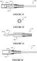
- FIG 10B illustrates an alternative sampler 500 that is for example designed to hold and actuate a swab assembly 501 as seen in figure 10A and figure 11 .
- the sampler 500 may include a trigger 502 that can be actuated by a user in order to cause the swab 503, held pre-swabbing in a protective sleeve 504 that may be capped by a cap 505, to be moved by virtue of a sampler ram or push rod (not shown).
- Such movement may be a push and retract movement where the swab head 503a is moved over an item such as a tongue of an animal, in order to take a saliva sample.
- the movement may be quick.
- the sampler 500 has no jaw of sample taking region unlike the samplers as prior described.
- the sampler 500 provide for the same of similar GPS and timing and reading functionality as is herein described with reference to the other samplers, and such may be removably carried by the sampler 500 or permanently.
- FIG. 1 A suitable method of actuating the sampler as previously described to obtain a sample is illustrated in Figure 1 .
- the magazine 200 is rotatable within sampler 1, so that unused collecting devices 250 can be sequentially moved into the active collecting position.
- the sampler 1 comprises actuating means to actuate, e.g., a ram, to push the active collecting device out of the chamber of the magazine 200, through the sample removing region 400 and toward the storage container.
- the ram pushes the collecting device 250 through the sample removing region 400, the cutting end of the punch pushes through the item (e.g., ear or other part of the animal) to cut a sample plug from the item.
- the ram may be actuated via a handle or trigger of the sampler.
- any of these exemplary samplers 1, 1', 1", 1''' may comprise additional sensing, processing and connectivity components to improve the ease, efficiency, convenience, security and/or accuracy of the sampling process and subsequent downstream sample analysis.
- the sampler 1, 1', 1", 1''' as seen in Figures 1 to 4 may comprise a tag reader 1500 configured to scan or read an identifier on an animal tag that is associated with the animal from which the sample is to be taken/has been taken.
- Animal tags are known in the art and have been widely used to provide a unique identification of each animal.
- the animal tag may comprise a human readable identification component, such as an alphanumerical sequence printed or otherwise provided on the animal tag.
- the animal tag may additionally or alternatively comprise a visible machine readable component such as a linear barcode or a matrix barcode such as quick response (QR) codes.
- the animal tag may additionally or alternatively be an electronic identification (EID) tag, e.g., a radio-frequency identification (RFID) tag, a near field communication (NFC) tag, which comprises electronically stored information and means for transmitting this information to the tag reader.
- EID electronic identification
- RFID radio-frequency identification
- NFC near field communication
- the animal tag may be embedded (e.g., subcutaneously) in the animal; in other cases, the tag is attached to the animal (e.g., to the animal's ear) such that at least a portion of the tag is visible to the user; in yet other cases, the tag is marked onto the animal, e.g., via branding, tattooing.
- the RFID system may operate in a suitable frequency range, e.g., low frequency (FL), high frequency (HF), ultra high frequency (UHF).
- FL low frequency
- HF high frequency
- UHF ultra high frequency
- the frequency range may be selected according to effectiveness over the distances required, according to regulation or standards, and/or so as not to interfere with other RFID systems (as discussed in more detail below).
- the tag reader 1500 is accordingly configured to read, sense, scan, capture and/or record one or more identification components from the animal tag.
- the animal tag reader 1500 is configured to be able to capture identifiers from more than one type of animal tag, for greater versatility across a range of different environments and scenarios.
- the tag reader 1500 is configured to read electronically stored data from an EID tag.
- the animal tag may comprise a passive RFID transponder that is powered inductively by the animal tag reader.
- the animal tag may be an active RFID tag.
- the tag reader 1500 comprises an RFID reader antenna configured to read the electronic ID transmitted by the animal tag across a specific carrier frequency or frequency band.
- the configuration of the RFID system conforms to ISO standards 11784 and 11785.
- the RFID system is preferably a low frequency (LF) system, and operates across the ISO-compliant carrier frequency of 134.2 kHz.
- LF low frequency
- the RFID system could be instead compliant with other national or regional standards relating to animal identification and tracing, and may therefore operate at or across other frequencies as appropriate.
- the tag reader 1500 may additionally or alternatively comprise a barcode or QR code scanner for use with tags that have no RFID capability.
- the tag reader 1500 may comprise a barcode scanner, image scanner, a camera or other image capturing means.
- the tag reader 1500 of sampler 1, 1', 1", 1''' may further comprise a processor running image recognition software for processing and interpreting the captured barcode image.
- the tag reader 1500 may simply record the barcode image, to be transferred to a separate storage location, apparatus, database, server, for subsequent processing and interpreting.
- the tag reader 1500 may be a camera 1800 for recording human viewable/readable animal ID or ID components, such as alphanumeric serial numbers, from the animal tag.
- the recorded image may be processed using image recognition and processing software, whether this is run on board the sampler, or after the data has been transferred to a remote server.
- the camera 1800 could also be used to take photographs or videos of identifying features of the animal, for example, photographs of the animal tag, biometric data such as a retinal scan of the animal, visual patterns on the animal such as colouring variation or distribution of spots, or other identification features such as visual brands on the animal, ear notches.
- biometric identification data may be captured in addition to, or instead of, identification from an animal tag associated with the animal.
- the camera 1800 may be provided with one or more accessories (whether integrally formed with the camera or not) such as a flash, laser pointers, for use in low-light conditions and/or as a laser "sight" to increase accuracy of focus on the ID component or other identifying features of the animal before/when capturing the photograph.
- accessories may include rangefinders (e.g., laser rangefinders), proximity sensors, infrared sensors, to aid with focusing and capturing of photographs and optionally also to obtain more information about the images captured e.g., distance.
- the user may be prompted to scan the animal tag and/or capture other animal identification data immediately before and/or immediately after taking the sample of the animal.
- This prompting may be by way of visual, audio or haptic feedback.
- a countdown timer may be visible and/or audible.
- Timing between the scanning and sampling steps may be restricted, regulated, recorded or monitored, as discussed in more detail below.
- the scanning or transmission of the animal EID may be automatically activated, for example, actuating the trigger of the sampler to take the sample may simultaneously activate the tag reader 1500 to read the EID and/or capture the image.
- the sampler is configured to so that there is a predetermined time limit between (1) scanning or reading of the animal ID and (b) taking the sample or taking of a sample marked as valid (e.g. a validated sample) and that accordingly will or should be treated as valid in subsequent processing, (or vice versa).
- a sample marked as valid e.g. a validated sample
- This time limit may be factory set. This time limit may be programmable by an authorised user, so that it may be adapted for different scenarios.
- the user may be notified (via sound, visual, haptic feedback) and the user will need to rescan the animal tag before the sample (or a validated sample) can be taken. That is, the sampler may be blocked or deactivated such that the punch of the collecting device cannot be actuated unless the animal tag is rescanned.
- the sampler may be deactivated, e.g., the actuator 130 may be prevented from being actuated (for example via solenoid pins that lock the push rod), the sampler may power off or go into standby mode, until the user performs one or more authorisation steps, e.g., by inputting user login details (may be user's login details or a supervisor's login details), or by capturing user (or a supervisor's) credentials e.g., sensing, reading, and/or recognising one or more identifiers associated with the user, such as a barcode, QR code, EID on a user's ID card, and/or biometric data such as the user's thumbprint, eye scan. Further, the user may also be required to restart the sampling process once the authorisation step(s) have been performed, in order to reactivate the sampler.
- a data warning tag is added to the data associated with the sample, so that a laboratory analyst will be aware that the time limit was breached during that particular sampling instance. Ie the sample is not valid or is not a validated sample. Exemplary embodiments for associating data with the sample, e.g., via an ID on the collecting device or storage container, are described in more detail below.
- the sampler could record two time stamps, one at the time the animal tag is scanned, and another at the time the sample is taken. The duration between the two time stamps may then be assessed, e.g., at the laboratory, to determine if too much time elapsed between these two events. The sample may then be treated as non-validated sample.
- the identification of these events is performed automatically by the sampler or associated portable device, and cannot be modified by the user.
- a proximity or magnetic switch 1550 may be provided in a suitable location to confirm that the collecting device 250 or punch 251 has moved, e.g., out of magazine 200, or into storage container 500. This automatic detection can therefore be linked unambiguously to the sampling action.
- the sample ID reader may be positioned to only capture the ID of the actual collecting device while it is moving to take a sample or after it has moved into the storage container after taking a sample. Accordingly, the time of the reading of the sample ID could be used as an unambiguous confirmation of the sampling action.
- the required scanning process may either require the animal identification data to be captured before or after taking the sample. Where the scan is done after taking the sample, the procedure would not prohibit a sample from being taken (e.g., by deactivating the sampler) if the time limit is breached, but the sample could be tagged with data warning tags as described above.
- a multi-scan process may be implemented. For example, the user may be required to scan the animal tag, take the sample, then re-scan the animal tag. Optionally, this must all be done within a predetermined time period. This will help to reduce the risk of cross-sampling fraud.
- the animal tag reader 1500 may be provided integrally with (and permanently attached to) the sampler, as shown in Figures 1 and 2 .
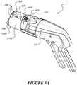
- the animal tag reader 1500 may be provided on a reader unit 1000 that is removably attachable to the body 100 of the sampler, as shown in Figures 3 and 4 .
- the detachable reader unit 1000 may also comprise inbuilt memory storage 1100 and/or means for receiving removable memory storage, e.g., memory cards, USB, for storing the animal ID.
- the animal ID data and other data such as time stamp data may be written to the memory storage to be recorded thereon.
- the reader unit 1000 may transmit the animal ID and other data to an external device or database without storing the data on the reader unit 1000.
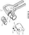
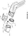
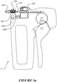
- the detachable reader unit 1000 may be configured to be reversibly attached to the sampler via any suitable attachment means, e.g., snap-fit, interference fit, screw-fit, a lug and slot connection (as shown in Figures 3a to 3c ), clamps.
- any suitable attachment means e.g., snap-fit, interference fit, screw-fit, a lug and slot connection (as shown in Figures 3a to 3c ), clamps.
- the animal tag reader 1500 may be physically separate from the sampler.
- the animal tag reader 1500 may comprise a smartphone 2000 or other portable computing device, having a camera which may function as a barcode/QR code scanner, and/or having RFID/NFC capabilities for receiving EID data from the animal tag.
- the smartphone 2000 may run software or applications to provide a user interface to facilitate the link between the smartphone and the sampler. Additionally, the smartphone 2000 may perform some or all of the image recognition and processing of the captured data. Alternatively, some or all of the raw captured data may individually or collectively be transmitted (whether via a wired or wireless connection) to a server or database for further processing.
- the sampler may be wirelessly connectable to a smartphone 2000 via, for example, Bluetooth, Bluetooth low energy (BLEW), Wi-Fi, infrared, NFC, mobile networks such as GSM, GPRS, 3G, 4G LTE, to perform one or more of the following functions: user authorisation, data transfer, user interaction.
- BLEW Bluetooth low energy
- Wi-Fi wireless local area network
- NFC wireless local area network
- mobile networks such as GSM, GPRS, 3G, 4G LTE
- the sampler is preferably able to connect wirelessly with a smartphone or other portable computing device to facilitate one or more of these functions.
- the sampler may comprise a holder or other means for temporarily attaching a smartphone 2000 or other portable computing device to the body 100 of the sampler.
- some embodiments may provide means for wired data connectivity between the two devices (for example, a USB plug connection) while the smartphone 2000 is mounted to the sampler.
- the sampler 1, 1', 1", 1''' also comprises a sample ID reader 1600 to read, sense, scan, capture and/or record one or more identification components of the collecting device 250 and/or storage container 500.
- the plunger 257 or punch 251 of the collecting device 250 may comprise a machine readable EID tag, such as an RFID tag.
- the RFID system may be selected according to the anticipated manufacturing and use conditions of the sample collector. For example a typical passive tag, active reader system operating at low frequency can provide robust identification devices suitable for embedding in molded plastic components at a unit cost that is appropriate. Other systems, such as NFC, or passive or active tag systems operating in the high frequency (HF) or ultra high frequency (UHF) range may also provide affordable, effective solutions.
- HF high frequency
- UHF ultra high frequency
- the electronic ID transmitted by the tag on the collecting device 250 or storage container 500 is preferably across a carrier frequency that is different from the carrier frequency of the animal tag ID (if an RFID animal tag is used or intended to be used).
- the sample ID tag preferably does not operate over 134.2 kHz, which is the ISO-compliant frequency for the animal EID. This will ensure that the two tagging systems do not interfere with each other.
- the sample ID system operates at 125 kHz.
- the sample ID reader 1600 may be integrated to the sampler, or mounted to the sampler, adjacent the position that the sample, the collecting device 250 or the storage container 500 occupies before or after the sample has been taken, and/or adjacent the position that the collecting device 250 passes through while taking the sample. Examples of suitable locations of the sample ID reader 1600 are shown in Figures 1 to 4 respectively.
- the sample ID reader 1600 may be located on the detachable reader unit 1000, adjacent where the collecting device 250 moves into the storage container 5000 when the sample is taken.
- the device has means for selectively reading only the ID of the actual collecting device 250 or punch 251 that is currently being used to take the sample.
- the other collecting devices/punches may be shielded from being scanned by the sample ID reader 1600, e.g., by manufacturing (at least part of) the magazine from an RFID blocking material, Faraday's cage.
- sample ID reader may be tuned to very close range, such that it only reads a collecting device 250 or punch 251 that is directly adjacent to it (this being the collecting device/punch that has been moved into position, ready for use).
- the sample ID reader is located away from the pre-use position of the collecting devices/punches, and positioned adjacent where the collecting device 250 or punch 251 will pass through while taking the sample, or where the collecting device 250 will end up after taking the sample.
- This provides a means for automatically and unambiguously detecting the sampling action. The exact time of the sampling action may therefore be linked to the time that the sample ID reader captures the sample ID, and this data may be used to implement the restricted time limit between capturing the animal ID and taking the sample, as described above.
- the sample ID reader is configured to scan/read the sample ID as appropriate, e.g., the sample ID reader may be a camera, barcode scanner, smartphone with camera.
- the sampler may comprise GPS or other 3D positional recording or tracking systems for providing location data. Additionally or alternatively, the sampler may also comprise other forms of positioning technology to provide location data, including but not limited to cell phone network based triangulation, Wi-Fi-based geolocation by the correlation of the SSID, MAC address or other identifiers of the Wi-Fi access point with a public or private database of locations associated with the Wi-Fi access point.
- this form of positional information may be supplemented with one or more other commonly used localisation techniques.
- Such techniques may include the estimation of position based on signal strength from one or more access points, fingerprinting, angle of arrival based techniques where more than one antenna or access point is available, or time of flight techniques.
- the sampler may comprise a GPS or other positioning technology module 1700 to obtain or estimate the location where a sample was taken.
- the positioning technology module may be provided either as a component either separate and preferably connectable or associable with the handheld body of the sampler, or may be integral with the handheld body of the sampler. Where provided separate from the handheld body, the positioning technology module 1700 may be provided by the smart phone 2000, where present. It is contemplated that the positioning technology module 1700 may additionally be provided by any other commonly available device capable of
- the smart phone may be located near to the sampler, such that the location data may be transmitted to the sampler.
- Such a range limitation may be provided by using short-distance communication protocol, such as Bluetooth or Wi-Fi.
- short-distance communication protocol such as Bluetooth or Wi-Fi.
- the smart phone may be carried by the user while sampling, or may be located nearby such as on a fence post, in a nearby vehicle.
- Additional security measures may optionally be employed, e.g., back-up position tracking systems, additional cell tower metadata, assisted GPS, to prevent GPS spoofing fraud, verify the collected location data, and/or increase accuracy of the location data.
- the accuracy of location data is desired to be such that it is possible to distinguish between farms or regions within farms, or individual ocean areas, but not necessarily to the level of individual animals or plants.
- more accurate location data may be able to be provided, such that it is possible to determine between specific areas of land or sea.
- the location data may then be recorded and linked to the sample (e.g. sample ID, animal ID, other relevant information associated with the particular sample). This linking of the data may be performed onboard the sampler, via a connected device such as a smartphone 2000, and/or after the datasets have been transferred to a server or database.
- sample ID e.g. sample ID, animal ID, other relevant information associated with the particular sample.
- This linking of the data may be performed onboard the sampler, via a connected device such as a smartphone 2000, and/or after the datasets have been transferred to a server or database.
- the location data is linked to the sample it may be desirable, in order to prevent fraud, to provide a time limit between the sample being taken and the sampler acquiring the location data from the positioning technology module 1700. If the time between the sample being taken and the acquiring of the location data exceeds the time limit, the sampler may either reject the sample or record this information for assessment at the laboratory. This may go at least some way in preventing fraud by sampling of an animal in a first location, but the provision of location information from a second location.
- the sampler may require that the location data be timestamped within a particular time period. This may further prevent the spoofing of positioning information and the recording by the sampler of inaccurate location data.
- the time timestamps and locations of each recorded sample location may be compared against the time between each related sample, in order to determine if the distances travelled between each successive sampling was possible in that amount of time. Where this analysis is conducted, some leeway may be provided dependent on the accuracy and type of positioning technology that is utilised.
- images of the sample location may be captured immediately before, during or immediately after the sample is taken, and the data linked with each other to provide a comprehensive collection of data tags associated with a particular sample. For example, actuating the trigger of the sampler to take the sample may simultaneously initiate the recording of these additional data.
- Increasing the number and variety of data tags associated with a particular sample will generally increase the security of the sampling process, sample tracking and sample processing. Further, automating the collection of these data will reduce labour costs by eliminating or reducing steps which may previously have been done manually, such as writing down the date and time as each sample is taken.
- Location data or other information, as described above, that is captured and associated with a particular sample may be stored on the sample tube 500, or may be recorded on the sampler itself, or on a connected device such as a smartphone 2000, where present. Recorded data on the sampler or connected device may be instantaneously uploaded to a desired location for review at the laboratory, or may be manually uploaded, such as by reading the data off a memory card associated with the sampler, at a later time.
- location data or other information is associated with a sample and stored or transmitted, it may first be encrypted by either the sampler or associated connected device prior to storage or transmission. This encryption may assist in preventing fraudulent modification of the data, such as by the insertion of a falsified data stream.
- the information required for decrypting the data may be provided at an authorised end source, such as a laboratory where the samples are reviewed.
- An additional layer of security may be provided by requiring operator authentication prior to using the sampler, and/or prior to taking a sample.
- Operator login may be performed via direct operator input to the sampler, via switches, touch screens, keypads, provided on the sampler.
- the operator may instead log in via an application on a connected device such as a smartphone 2000.
- the user's credentials may be obtained by sensing, reading, and/or recognising one or more identifiers associated with the user, such as a barcode, QR code, EID on a user's ID card, and/or biometric data such as the user's thumbprint, eye scan.
- identifiers such as a barcode, QR code, EID on a user's ID card, and/or biometric data such as the user's thumbprint, eye scan.
- the user may be prompted to input user credentials intermittently or regularly throughout the entire sampling process.
- the sampler and/or connected device may be configurable such that the frequency of the user input prompts may be varied depending on the security required for a particular situation.
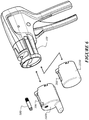
- FIG. 3 and 4 illustrate one particular configuration of a sampler 1" comprising a standalone reader unit 1000, which is attachable and detachable from the sampler body 100.
- This reader unit 1000 preferably comprises the animal tag reader 1500, the sample ID reader 1600 and memory storage 1100.
- the reader unit 1000 may further comprise processing system including a communication module, e.g., for wireless communication with a smartphone.
- the detachable reader unit 1000 may also comprise a GPS module 1700, or other position tracking components.
- the detachable reader unit 1000 may also comprise a camera 1800 which, in some cases, may function as animal ID reader 1500 and/or sample ID reader 1600.
- the detachable reader unit 1000 may comprise essentially all the "smart" components of sampler 1".
- the reader unit 1000 may be standalone, in that it may be powered by its own battery 1900, which may be rechargeable via any known method, such as a removable rechargeable battery, USB charging, wall socket charging, inductive charging.
- the reader unit 1000 is preferably completely sealed and weather resistant, water resistant or waterproof.
- the reader unit 1000 may be hot swappable from the sampler while the sampler remains in operation. That is, the reader unit 1000 may be replaced with another reader unit while the sampler remains in operation. This may be done when the memory storage 1100 is full, so that the data may then be uploaded to a server or database.
- the reader unit 1000 may be hot swappable from the sampler while the sampler remains in operation. That is, the reader unit 1000 may be replaced with another reader unit while the sampler remains in operation. This may be done when the memory storage 1100 is full, so that the data may then be uploaded to a server or database.
- the reader unit 1000 may be provided by the on-board functions or connected functions of a smart phone 2000 where present, or may alternatively be provided as another separate element, not attachable or detachable to the sampler body 100.
- the reader unit 1000 may also be able to be attached and detached to the sampler body 100, or may be provided proximate to the sampler body.
- the smart phone may be worn the user who is conducting the sampling, on the body or in their clothes.
- reader unit 1000 is comprised by the smart phone 2000 and/or other commonly available devices connected to it,
- the reader unit 1000 is not attachable or detachable to the sampler body 100 it may be provided proximate to the sampler such that it is still able to receive and record animal ID information from the sampler.
- the sampler and reader unit 1000 may communicate by any commonly used communication platforms such as RF, Wi-Fi, Bluetooth.
- the reader unit 1000 While not attached to the sampler body, the reader unit 1000 would preferably be sufficiently proximate to facilitate communication between the sampler and reader unit.
- the reader unit 1000 may be located on the person of the user of the sampler, on the ground or a fence post nearby to where the sampling is taking place, or in or on a vehicle nearby.
- the standalone, hot swappable "smart" reader unit 1000 may be removed from the sampler, and the sampler used without the smart reader unit.
- a replacement storage container holder 2200 may be attached to the front of the sampler, so that the sampler may then operate as a basic, "non-smart” device.
- This "non-smart" storage container holder 2200 may comprise a holder for a single storage container 500, or may comprise a magazine for holding a plurality of storage containers 500.
- the sampler may be used with the "smart" reader unit 1000 to provide an additional level of security and reduce the risk of tampering, while for lower risk environments, the reader unit 1000 may be removed (and optionally replaced with a standard sample tube holder 2200) to perform less secure, but quicker and (potentially more cost-effective) sampling. Accordingly, this provides several options for the user, i.e., a basic, low-cost system, which may be subsequently upgraded to a "smart" system if/when required.
- the sampler body 100 may not comprise a power supply and/or electronic components, and therefore relies on the detachable reader unit 1000 for the "smart" components of the system.
- the standalone, hot swappable "smart” reader unit 1000 may be configured to receive both the storage container 500 and collecting device 250.
- the cassette 303 received by the sampler 1''' may be provided in two different forms, a "smart" cassette comprising, e.g., animal ID reader 1500 and/or sample ID reader 1600, memory storage 1100, (as illustrated in Figure 5a ) and a basic "non-smart” cassette. That is, the sampler 1''' may be configured to receive either a "smart" cassette/reader unit, or a basic "non-smart” cassette which would still allow the sampler to perform the basic sampling procedure.
- a separate smart device 2000 may be provided in order to provide at least some of the herein described smarts of the system.
- the smart device may be used to scan a EID tag, such as an RFID tag, on the plunger 257 or punch 251 of the collecting device 250 or the punch 251, then also taken an associated animal ID.
- the associated animal ID may also be in the form of an RFID tag, or may be in the form of any one or more of the other forms of animal ID herein described.
- the smart device may scan the RFID tag of a collecting device 250 or punch 251, then also take a location data point from the on-board positioning systems of the smart phone. These pieces of information may then be associated with each other and stored on the smart device, for later transfer or analysis.
- any one or more other forms of animal ID may also be taken simultaneously, or preferably within a predetermined time period.
- the user may take a photograph of the animal using the smart device 2000.
- a maximum time threshold after sampling, or after the scanning of the collecting device or punch may be required in order for the animal ID to be validly recorded.
- the smart device 2000 may reject the sample and require re-sampling, or may record the fact that the threshold was surpassed along with the other animal ID information.
- either or both of the smart device and sampler may be configured such that the collecting device 250 or punch 251 may only be scanned during the sampling process.
- Such a configuration may involve shielding of the collecting device or punch prior to sampling, or a particular location of the smart device 2000 in relation to the sampler body.
- the one or more forms of animal ID which may be sensed or captured by the smart device may either be stored on the smart device, for immediate or deferred transmission to a desired repository, such as the laboratory, or may be transmitted to and stored on the associated collecting device 250 or punch 251.
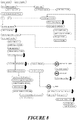
- FIGS 7 and 8 are schematic flow charts that detail particular exemplary embodiments of the sampling device and the sampling process. It will be appreciated that the steps and sequencing depicted in these flow charts are provided for explanatory purposes. Accordingly, any one or more of the components described may be modified or eliminated, without departing from the scope of the invention, as defined in the claims.
- processing unit such as microprocessor 1150 controls the operation of the sampler, such that on wake up (e.g., after accepting user credentials) it may first query the location coordinates of the sampler, by accessing GPS module 1700 (if provided).
- GPS module 1700 if provided.
- alternatives to the GPS module may be other positional tracking or triangulation systems, acquired through user input.
- the most recent location coordinates stored in microprocessor memory 1160 is used as the initial location variable, and this is periodically updated by the GPS module 1700.
- an LED 1180 or other audio, visual or haptic feedback component on the sampler 1, 1', 1", 1''' returns a signal that the GPS is locked and/or warming up, so that the user is informed to wait until the GPS has successfully returned the GPS coordinates.
- the user may then insert a storage container 500 into the storage container holder 300.
- inserting the storage container triggers a micro switch 1170 or other switch, which then triggers the next step of the operation (e.g., reading the animal tag). Triggering of the micro switch may help to conserve the battery of the sampling device (by turning the animal tag reader 1500 and/or sample ID reader 1600 off when not needed), and/or to ensure that the sample is taken only when a storage container 500 is in place.
- the storage container 500 may be inserted before or while the GPS module or other positioning technology is obtaining the GPS coordinates or other location information.
- a micro switch need not be provided, and the sampler may be ready to use as soon as the GPS coordinates have been obtained.
- the GPS requirement may be overridden by an authorised user, e.g., for use in locations where GPS signals may be weak or unavailable. It is preferable that the override to allow sampling to continue without location data is only able to be operated when the signal or information required to determine positioning is not available, or is below a desired threshold, for a predetermined period of time, or by a user having sufficient privileges.
- the sampler In high-risk environments it may be preferable to omit the override, so that the sampling may not continue without location data being provided. In such a situation, in order to ensure that the sampler is able to be used in the maximum number of physical locations, such as indoors or where there is legitimately no capacity to acquire location data, it may be preferable to provide the sampler with multiple positioning technologies, or provide alternative forms of animal ID that must be provided in place of the location data. Where alternative forms of animal ID may be provided, it is preferable that they are only available after a predetermined time has passed with no location data being able to be acquired.
- a new collecting device 250 or punch 251 must be individually inserted before taking the next sample.
- the collecting device/punch may be inserted into the sampler 1 either before or after the storage container 500 has been inserted into the storage container holder 300.
- the user may actuate (e.g., rotate) the magazine to position a new collecting device 250 in place, either before or after the storage container 500 has been inserted into the storage container holder.
- Corresponding visual, audio or haptic feedback e.g., via LED 1180 may be provided to prompt the user to insert the tube 500 and/or collecting device/punch, and subsequently to notify the user that the device is ready to scan the animal tag 2100.
- the user then scans/captures the animal ID (e.g., via RFID, or by taking a picture or barcode scan) and the animal ID is stored in memory 1160.
- a timer may be activated which starts the countdown to the predetermined time limit during which the sample has to be taken. This countdown may be indicated to the user via audio, visual or haptic feedback.
- the punch 251 or collecting device 250 passes through the sample ID reader 1600, the ID of the punch 251 or collecting device 250 is read and stored in memory, e.g., memory storage 1100 of reader unit.
- a time stamp may be recorded simultaneously, or at any other time during the sampling process, as long as the time stamp is unambiguously associated with the individual sample taken.
- the microprocessor 1150 may initialise any one or more of the following responses.
- a warning may be displayed to the user via visual, audio or haptic feedback.
- Micro switch 1170 may then switch off and the user is prompted to enter a password (or other response, e.g., remove the storage container and reposition it in place in the storage container holder 300) to reactivate the micro switch. This may then reactivate the animal tag reader 1500 and the user is then prompted to rescan the animal tag and subsequently take the sample within the time limit.
- the user may be prompted to rescan the animal tag, and the rescanned ID replacing the original ID variable in memory 1160. Subsequently the user may then take the animal sample within the time limit.
- the user may continue to take the sample, but a data warning tag is generated, linked to the sample, and stored in memory. This way, when the data is processed subsequently, the analyst will be alerted to the fact that that particular sample was taken outside of the prescribed time limit. This step of generating a data warning tag may be applied to any of the above response processes.
- a first time stamp is recorded at the time when the animal ID is captured and a second time stamp recorded at the time the sample is taken (or vice versa depending on the sampling procedure, i.e., if the user is required to first take a sample before recording the animal ID, a first time stamp may be recorded as the sample is taken, and the second time stamp recorded when the animal ID is captured).
- the time stamp data may be analysed to flag which (if any) samples were processed outside of the required time limit.
- the time stamp recording may additionally or alternatively be used to record other steps of the sampling process, e.g., recording of sample ID, sealing of the sample tube, entering and authentication of user credentials, and the time duration between any two steps may be analysed (whether directly by the processor on the reader unit, or at the laboratory).
- a warning may also be provided if the ID of the punch 251 or collecting device 250 is not successfully obtained. This may occur, for example if the magazine of collecting devices is empty and needs to be refilled, or if the RFID of the punch or collecting device 250 was not properly scanned/captured. In such cases, a visual, audio or haptic warning may be activated, and the user may be prompted to insert a new collecting device 250, and restart the entire sampling process.
- the time between taking the sample and sealing the sample tube 500 may additionally or alternatively be restricted. That is, the or another timer may be activated (or a second time stamp recorded) when the sampler 1''' is actuated to drive the collecting device 250 and take the sample.
- the timer may stop or a time stamp recorded when the sampler 1''' is actuated to drive the seal into the sample tube 500, and if this step is not within a pre-set time limit, this may trigger one or more responses, e.g., deactivation of the sampler, audio, visual, haptic feedback, as described above in relation to the duration between capturing of animal ID and taking the sample.
- a warning data tag may be recorded and reviewed at the laboratory.
- a first time stamp may be recorded when the sample is taken and/or a first time stamp may be recorded when the animal ID is captured, a second time stamp recorded when the sample tube is capped, and the time stamp data associated with the sample in memory, to be subsequently analysed at the laboratory.
- each sample taken has an associated record of data, which may be stored in memory or transmitted to an external device.
- the record of data comprises at least i) the animal ID and ii) sample identification information.
- the sample identification information is associated with the collecting device and/or storage container (e.g., via machine readable code or EID on the collecting device and/or storage container).
- the sample identification information could be a linked to the specific order in which an ordered/numbered array of collecting devices and/or storage containers is provided to the sampler.
- the record of data further comprises additional information associated with the sample as described above, e.g., time stamps, data warning tags, photographs, GPS data, user credentials, Accordingly, each sample may be automatically associated with a record of multiple pieces of information related to the particular sample, to improve the efficiency and security of the sampling process and prevent fraud.
- the data stored in the microprocessor memory 1160 may be transferred to memory storage 1100.
- the device may then be initialised for the next sample, e.g., the microprocessor memory 1160 may be erased.
- the microprocessor may put the device into sleep or standby mode if the sampler is not used for a predetermined time period, e.g., 30 minutes.
- the microprocessor may activate GPS module 1700 to update the GPS coordinates, as discussed above.
- the feedback may be unique to the particular event or a set of related events, e.g., a specific LED colour, a specific number or pattern of audio beeps, to help the user identify the exact issue/event that is occurring.
- the feedback or warning may be displayed on the user interface of a connected device, e.g., smartphone 2000.
- the preferred methods herein described help improve tamper resistance of the sampling process.
Landscapes
- Life Sciences & Earth Sciences (AREA)
- Health & Medical Sciences (AREA)
- Engineering & Computer Science (AREA)
- Biomedical Technology (AREA)
- General Health & Medical Sciences (AREA)
- Environmental Sciences (AREA)
- Molecular Biology (AREA)
- Surgery (AREA)
- Animal Behavior & Ethology (AREA)
- Heart & Thoracic Surgery (AREA)
- Public Health (AREA)
- Veterinary Medicine (AREA)
- Medical Informatics (AREA)
- Pathology (AREA)
- Zoology (AREA)
- Animal Husbandry (AREA)
- Biodiversity & Conservation Biology (AREA)
- Birds (AREA)
- Biotechnology (AREA)
- Genetics & Genomics (AREA)
- Nuclear Medicine, Radiotherapy & Molecular Imaging (AREA)
- Physics & Mathematics (AREA)
- Electromagnetism (AREA)
- Oral & Maxillofacial Surgery (AREA)
- Vascular Medicine (AREA)
- Epidemiology (AREA)
- Automatic Analysis And Handling Materials Therefor (AREA)
- Sampling And Sample Adjustment (AREA)
- Investigating Or Analysing Biological Materials (AREA)
Description
- The present invention relates to an apparatus for sampling. The invention is defined in the claims.
- To improve the tracking of livestock and to facilitate DNA testing, biological samples may be collected from animals. The sample is usually cut from an animal using a sampling device and is placed in a storage compartment for laboratory analysis.
- For disease control and quality control, it is becoming increasingly important to be able to individually identify each animal with a unique code. This is typically achieved by tagging of livestock which has recently become compulsory in many countries worldwide. The tag, attached to the animal, e.g., to the animal's ear(s), has a unique identifier on or transmittable by the tag. These unique codes can be registered centrally, together with additional data related to the animal, farmer. Further, the unique identifier allows the sample to be unambiguously linked to the animal in question. Accordingly, in an outbreak of a disease, the source can be traced and the disease may be controlled more effectively and efficiently.
- Despite the increased security resulting from the use of identification tags, there still remains the risk of error or fraud, e.g., cross-sampling fraud, where the sample from one animal is linked to the ID of another animal. This may occur during the sampling process if there are insufficient measures to prevent tampering of the samples.
- Further, the sampling process is often labour intensive and prone to errors and inaccuracies, as the process typically requires logging of multiple pieces of information associated with each sample, concurrently while taking a sample.
-
WO2005/050412 A2 includes an apparatus, and corresponding method, for taking a sample. During the sampling process; the sampling location is determined, the operator records sampling-related data, operator's ID, sampling time and date, handwritten or machine-encoded identifiers of the sample media and its storage container. A barcode reader may also be used for tracking information. Further, the operator may scan an ID label of a storage container using the camera. Similar to the sample ID label, the storage container's ID label is correlated to the sample, sample location, sample time, etc. -
US 6,659,338B1 discloses a sampler (Fig 1 ) comprising a handheld body with a storage container holder (magazine 3), sample collecting device holder (magazine 10 in handle 11), a sample removing region (8) and an actuator adapted to drive a sample collecting device.US6,659,338B1 discloses a portable data entry device as the reader unit in Fig 22 which has a sample identification reader (barcode reader 4) and an animal ID reader (display 1). - Accordingly, it is an object of the present invention to provide apparatus for collecting and handling samples that goes at least some way toward overcoming the disadvantages of known collecting methods and/or that will at least provide the public with a useful choice.
- Biological samples as referenced herein may include for example, animal tissue such as flesh, blood, hair, fur, saliva, sweat, urine, or plant tissue such as leaves, bark, roots or wood, or any other part of a plant or animal but particularly those that are made up of similar cells, or which perform a similar function. Tissue may come from plants and animals particularly, including pigs, goats, cattle, sheep, poultry, and fish. The animals may be production animals or companion animals or wild animals.
- In this specification where reference has been made to patent specifications, other external documents, or other sources of information, this is generally for the purpose of providing a context for discussing the features of the invention. Unless specifically stated otherwise, reference to such external documents is not to be construed as an admission that such documents, or such sources of information, in any jurisdiction, are prior art, or form part of the common general knowledge in the art.
- In a first aspect, the present invention may be said to be a system for taking a biological sample from an item, the system being defined in accordance with
claim 1. - In a second aspect the present invention may be said to be a sampler being defined in accordance with
claim 2. - Preferably the reader unit comprises memory storage and/or can receive removable memory storage.
- Preferably the memory storage can store item ID and sample information, that become associated with each other.
- Preferably the reader unit comprises a transmitter to transmit item ID and/or sample information to an external device. (e.g. a data storage or collection device).
- Preferably the reader unit comprises a rechargeable power supply.
- Preferably the collecting device holder is permanently engaged to the handheld body.
- Preferably, if the reader unit, when in the form engageable to the handheld body, is removed, the sampler is still able to function to remove a sample for the item.
- Preferably the reader unit comprises a sample identification reader, and wherein said sample information to be read by the sample identification reader comprises one or more of a machine readable ID and an electronic ID, associated with the collecting device.
- Preferably the reader unit comprises an item ID reader and wherein said item ID to be read by the item ID reader comprises one or more of a machine readable ID and an electronic ID, associated with the item from which the sample is to be taken. Preferably the reader unit comprises a sample identification reader and an item ID reader (to for example read ear tag ID)
wherein each reader is configured to capture respective identification information via compatible EID communication (preferably RFID). - Preferably the readers utilise different frequencies for EID communication.
- Preferably the sample identification reader operates at 125kHz and the item reader operates at 134.2 kHz.
- Preferably the reader unit comprises a camera configured for one or more of:
- a) capturing sample information,
- b) capturing item ID,
- c) obtaining supplemental data relating to one or more of:
- i) the item to be sampled,
- ii) location of sampling,
- iii) sampling procedure.
- Preferably the reader unit comprises a positional tracking system.
- Preferably the reader unit comprises:
- a) a timer and/or
- b) means for obtaining and recording and/or transmitting time stamps.
- Preferably the reader unit comprises an item ID reader, and
wherein the reader unit is configured to measure and/or record time between: - a) capturing said item ID and taking the sample, and/or
- b) taking the sample and capturing said item ID.
- Preferably if said measured and/or recorded time exceeds the predetermined time the handheld body or reader unit provides directly or indirectly (e.g. to an external device) audio, visual or haptic feedback.
- Preferably if said measured and/or recorded time exceeds the predetermined time the sampler (preferably the reader unit) prompts the user to take a new sample.
- Preferably if said measured and/or recorded time exceeds the predetermined time the sampler is deactivated by preventing said actuator(s) from being actuated.
- And preferably the user is required to perform one or more authorisation steps comprising one or more of inputting user login details and capturing user credentials, and/or to restart the sampling process, in order to reactivate the sampler.
- Preferably if said measured and/or recorded time exceeds the predetermined time, the sampler records a warning data tag associated with the sample, (preferably associated with said sample information and/or item ID and stored on memory storage of said reader unit).
- Preferably said predetermined time is between about 2 and 20 seconds.
- Preferably said predetermined time limit is between about 1 second and 5 minutes.
- Preferably said time limit is between about 5 and 10 seconds.
- Preferably the reader unit comprises a animal tag reader,
wherein the reader unit records a time stamp at the time when said animal tag ID is captured, and
wherein the reader unit records another time stamp at the time the sample is taken. - Preferably the reader unit comprises a sample identification reader, and
wherein the time of taking the sample corresponds to the capturing of said sample information on the collecting device as the collecting device is driven from the collecting device holder (preferably through the item) to remove the sample from the item. - Preferably the reader unit comprises a processor for controlling operation or operability of the sampler.
- Preferably the reader unit comprises a user interface for receiving and/or capturing user credentials.
- Preferably the reader unit comprises wireless communication means for transmitting data to one or more external devices.
- Preferably the reader unit is able to wirelessly transmit data to one or more external devices.
- Preferably the memory storage can store at least one of:
- A) item (e.g. animal) ID and sample information, and
- B) GPS data, photographs, time stamps
- Herein described is a method of taking a biological sample from an item and placing the sample into a storage container using a sampler, said sampler comprising a handheld body presenting:
- a sample collecting device holder adapted in use to accommodate a sample collecting device,
- an actuator adapted to drive the sample collecting device from the sample collecting device holder, (preferably through the item) to remove the sample from the item,
- an ID reader adapted to capture identification information (hereinafter item ID) associated with the item from which the sample is to be taken, the method comprising:
- a) supplying the sampler with a sample collecting device at the sample collecting device holder,
- b) driving the actuator to remove a sample from the item,
- c) capturing the item ID,
- Preferably the sampler is as herein before described.
- Preferable the item is an animal.
- Herein described as a mere example is a method of taking a sample from an item using a sampler, said sampler comprising
a handheld body comprising
a sample collecting device holder adapted in use to accommodate a sample collecting device, an actuator adapted to drive the sample collecting device from the sample collecting device holder, (preferably through the item) to remove the sample from the item, and
an ID reader (preferably removably engaged to the handheld body or located, during sampling, proximate to the handheld body), the ID reader adapted to capture identification information (hereinafter "item ID") associated with (and preferably carried by) the item from which the sample is to be taken, the method comprising: - a) supplying the sampler with a sample collecting device at the sample collecting device holder,
- b) driving the actuator to remove a sample from the item,
- c) capturing the item ID,
- Preferably the sampling time duration is compared (and is preferably recorded) with a predetermined time limit.
- Preferably the method comprising providing at least at least one of audio, visual and haptic feedback to a user if said sampling time duration is longer than said predetermined time limit.
- Preferably the method further comprising prompting the user to restart the sampling process if said sampling time duration is longer than said predetermined time limit.
- Preferably the sampling time duration when step (b) occurs after step (c) is monitored such that if the sampling time duration exceeds said predetermined time limit, said driving of the actuator is prevented by said sampler.
- Preferably if said sampling time duration is longer than said predetermined time limit and said sampler is deactivated by preventing said actuator(s) from being actuated, the user must perform one or more authorisation steps comprising one or more of inputting user login details and capturing user credentials, and/or to restart the sampling process s, in order to reactivate the sampler.
- Preferably the method further comprising recording or assigning a warning data tag associated with the sample if said sampling time duration is longer than said respective predetermined limit.
- Preferably said warning data tag is associated with said item ID. (preferably on a separate memory storage and/or on memory storage associated with said handheld body).
- Preferably said warning data tag is associated with information carried by one of both of said collecting device and storage container.
- Preferably the time of steps (b) and (c) taking place, are recorded as time stamps, and said recorded time stamps are associated with said sample. (preferably on a separate memory storage and/or on memory storage associated with said handheld body).
- Preferably said time stamps are recorded and associated with information carried by one or both of said collecting device and storage container, preferably on a separate memory storage and/or on memory storage associated with said handheld body.
- Preferably said time stamps are associated with said item ID information recorded preferably on a separate memory storage and/or on memory storage associated with said handheld body.
- Preferably the mere example of the method further comprising:
capturing identification information (hereinafter "sample information") associated with the collecting device as the collecting device is driven from the collecting device holder and (preferably through the item) to remove the sample from the item, wherein the time of taking the sample corresponds to said capturing of said sample information. - Preferably the predetermined time limit against which the sampling time duration is compared is between about 2 and 20 seconds.
- Preferably the predetermined time limit against which the sampling time duration is compared is between about 2 seconds and 5 minutes.
- Preferably the predetermined time limit against which the sampling time duration is compared is between about 5 and 10 seconds.
- Preferably the predetermined time limit against which the seal time duration is compared is between about 2 and 20 seconds.
- Preferably the predetermined time limit against which the seal time duration is compared is between about 5 and 10 seconds.
- Preferably the sampler includes a location sensor that can sense the geolocation of the sampler and record this information associated with information of said item ID and/or sample information.
- Herein described as a mere example is a sampling system to collect a sample from an item, comprising:
- a sampler comprising a handheld body defining a sampling region at where a sample collecting device can be held (and preferably is held),
- the handheld body carrying an actuator adapted to drive the sample collecting device to remove the sample from the item
- a reader unit removably engageable to said handheld body and comprising one or more of:
- a. a sample identification reader adapted to capture identification information (hereinafter "sample information") associated with the collecting device,
- b. an item ID reader adapted to capture identification information (hereinafter "item ID") associated with the item from which the sample is to be taken,
wherein in a second mode of use, the sampler, without the reader unit engaged to the handheld body, presents a sample collecting device holding region where said sample collecting device can be held. - Herein described is a sampling system to remove a sample from an item, comprising:
- a sampler comprising a handheld body defining a sampling region at where a sample collecting device can be held (and preferably is held),
- the handheld body carrying an actuator adapted to drive the sample collecting device to remove the sample from the item,
- a reader unit (preferably removably engageable to said handheld body, or able to be located remote yet proximate thereto), and comprising one or more of:
- a. a sample identification reader adapted to capture identification information (hereinafter "sample information") associated with the collecting device,
- b. an ID reader adapted to capture identification information (hereinafter "item ID") associated with the item from which the sample is to be taken.
- Preferably during said reader unit captures at least one of sample information and item ID when said sample is being removed.
- Herein described is a sampling system comprising
- (i) a handheld body to hold (and preferably holding):
- a. a sample collecting device holder adapted in use to accommodate a sample collecting device,
- b. an actuator adapted to drive a sample collecting device from the sample collecting device holder to take a sample from the item,
- (ii) a sample identification reader adapted to capture identification information (hereinafter "sample information") associated with the collecting device, and
- (iii) an ID reader adapted to capture identification information (hereinafter "item ID") associated with the item from which the sample is to be taken,
- Preferably GPS information is recorded at the time of sampling, said GPS information recorded with said item ID and sample information for subsequent processing.
- Preferably sampling time information is also recorded together with said GPS and item ID and sample information.
- Herein described as a mere example is a method of recording information and associating the information with sample taken from an item (preferably an animal), the method comprising:
using a sampler that can (a) receive a plurality of sample collecting devices that can remove a sample from the item and (b) record information of or carried by said item and (c) record information of or carried by each said sample collecting device, (if) recording geolocation information of the sampler at the time of taking a sample, (ii) recording information of or carried by said item and (iii) recording information of or carried by said sample collecting device and (iv) associating said geolocation information and information of or carried by said item and information of or carried by said sample collecting device together. - Preferably the time between at least one of (i) recording the geolocation of the sampler at the time of taking a sample, (ii) recording information of or carried by said item and (iii) recording information of or carried by said sample collecting device is also associated with said geolocation information and information of or carried by said item and information of or carried by said sample collecting device.
- Preferably the sampler carries a GPS or other geolocation sensing/capable device.
- Herein described as a mere example is a method of taking and storing a sample from an item, the method comprising:
- (i) taking an item identification reading (e.g. a photo of the item or a reading of an ID carried by the item) and digitally storing the read item identification,
- (ii) taking a sample from the item and locating the sample with a sample holder,
- (iii) taking an identification reading of the sample holder and digitally storing the read sample holder identification reading,
- (iv) taking a reading of the geolocation of the location of the item and digitally storing the geolocation reading,
- (v) recording the time of or time lapse between at least two of steps if-iv above.
- Preferably the order of steps (i) to (iv) is sequential and in the order of step (i) then step (ii) then step (iii) and step (iv).
- Preferably the steps (i) to (iv) are carried out in no specific order.
- Herein described as a mere example is a method of taking and storing a sample from an item, the method comprising:
- (i) taking an item identification reading (e.g. a photo of the item or a reading of an ID carried by the item) and digitally storing the read item identification,
- (ii) taking a sample from the item and locating the sample with a sample holder,
- (iii) taking an identification reading of the sample holder and digitally storing the read sample holder identification reading.
- Preferably the method further includes taking a reading of the geolocation of the location of the item and digitally storing the geolocation reading,
- Preferably the method also further comprises recording the time of or time lapse between at least two of steps if-iii above.
- The term "comprising" as used in this specification means "consisting at least in part of". When interpreting each statement in this specification that includes the term "comprising", features other than that or those prefaced by the term may also be present. Related terms such as "comprise" and "comprises" are to be interpreted in the same manner.
- This disclosure may also be said broadly to consist in the parts, elements and features referred to or indicated in the specification of the application, individually or collectively, and any or all combinations of any two or more said parts, elements or features, and where specific integers are mentioned herein which have known equivalents in the art to which this invention relates, such known equivalents are deemed to be incorporated herein as if individually set forth, without departing from the scope of the invention as defined in the claims.
- The invention consists in the foregoing and also envisages constructions of which the following gives examples only.
- Preferred embodiments of the invention will be described by way of example only and with reference to the drawings, in which:
-
Figure 1 is a cross-sectional view of a sampler that may be used with the methods herein described, -
Figure 2 is a perspective view of a different sampler, -
Figure 3a ,3b and3c show perspective and exploded views of another type of sampler, -
Figure 4a and4b show partial and close up views of a sampler, -
Figure 5a to 5d illustrate a sampling system, -
Figure 6 shows a removable smart reader unit and replacement standard storage holder unit, -
Figure 7 is a flowchart illustrating components (and associated operations) of a sampler, -
Figure 8 is a flowchart illustrating steps of a sampling process, -
Figure 9 illustrates a sampling system according to another embodiment. -
Figure 10A is a side view of a sample collecting device that may for example be provided for the purposes of taking a saliva swap, -
Figure 10B shows a sampler that may be used for the purposes of pausing the sample collecting device ofFigure 10A to be actuated, -
Figure 11 is a sectional view through section AA ofFigure 11 , -
Figure 12 is an end view ofFigure 10A , -
Figure 13 shows the swab of the sample collecting device ofFigure 11 in an extended condition, and -
Figure 14 illustrates the swab of the sample collecting device ofFigure 11 in a retracted condition. - The present disclosure relates to sampling methods that may utilise different variations of sampler hardware and consumable components such a tissue punches or swabs for obtaining biological samples from plants and animals particularly, including pigs, goats, cattle, sheep, poultry, and fish. Sampling from production and/or from companion animals such as cats, dogs and horses is envisaged. These biological samples may include for example, animal tissue, flesh, blood, hair, fur, saliva, sweat, urine. The invention relates more specifically to improvements in sampling, sample and animal correlation, meta-data collection, sample security and fraud reduction or prevention mechanisms for detecting, reducing and/or eliminating tampering of the sampling process or inadvertent errors during the sampling process.
- In one example of a
sampler 1" that may be used as seen infigure 3 and4 a magazine may be used that comprising a plurality of collectingdevices 250. Each collecting device may comprise apunch 251 having a cutting element for cutting a sample from the item (such as animal or plant material for example). Each collectingdevice 250 may also comprise a plunger that pushes the sample into a storage container held by the sampler by movement of an actuating means. If a magazine is included (integrally or removably) with the sampler, the magazine can be rotated, after a sample is taken, to bring another collecting device into position for taking another sample or the same or different item to be sampled, so that sequential samples can be taken efficiently. - The collecting
device 250 may comprise ahollow punch 251 having a cutter 255 configured to remove a sample from an organism. The collectingdevice 250 may also comprise a plunger 257 that is slidably movable within thepunch 251, to push the sample off the cutter 255 of the punch. - In other embodiments, as shown in
Figure 2 , the collectingdevice 250 may consist essentially of apunch 251, which is driven to punch a sample from the organism and then moved into astorage container 500. - In one embodiment as shown in
Figure 1 and9 , an example of asampler 1 that may be used, may comprise abody 100 having amagazine receptacle 200 for holding a plurality of collectingdevices 250, astorage container holder 300, and asample removing region 400. The sample removing region is located between the magazine receptacle and storage container holder. Anactuator 130 is actuable to drive the collectingdevice 250 frommagazine 200 intostorage container 300. - In another embodiment of a sampler, as shown in
Figure 2 , the sampler 1' may comprise abody 100 having astorage container holder 300 and a punch holder 50 that may be configured to hold asingle punch 251 associated with thestorage container 500. - In another embodiment of a sampler, as shown in
Figures 3 and4 , thesampler 1" may comprise abody 100 and a detachable scanning/sensing/reader unit 1000. In some preferred embodiments, thedetachable reader unit 1000 comprisesstorage container holder 300 anddigital memory storage 1100. In the embodiment shown, thedetachable reader unit 1000 holds asingle storage container 300, such that the user replaces thestorage container 300 after each sample is taken. In other embodiments, thedetachable reader unit 1000 may comprise a magazine for holding a plurality ofstorage tubes 300. For example, the magazine may be rotatable, so that new storage containers can be sequentially moved into the active collecting position for each sample. - The
body 100 of thesampler 1" may comprise ofmagazine receptacle 200 holding a plurality of collectingdevices 250, and asample removing region 400. The sample removing region is located between the magazine receptacle andstorage container holder 300. - In another embodiment of a sampler as shown in
Figures 5a to 5d , the sampler 1''' may be configured to removably receive (e.g., via snap fit or push fit or other fit) acassette 303. The cassette preferably carries acollecting device 250 such as one described above, astorage container 300 such as one described above, and (optionally) a seal orcover 260. -
Seal 260 may be provided to cover the open end of thestorage container 500 once the sample has been deposited within, for additional protection of the sample against contamination. In some embodiments, where thecollecting device 250 comprises a plunger 257 (that is slidably movable within thepunch 251, to push the sample off the cutter 255 of the punch), theseal 260 may also be adapted to push onto the plunger when the seal engages onto thestorage container 500, to thus push the sample off the punch into the storage container. - In the preferred form the
cassette 303 comprises a storagecontainer holding region 306 and acollecting device region 307. The two regions are preferably integrally connected, with asample removing region 400 defined therebetween. - The collecting
device region 307 is configured to hold thecollecting device 250 and seal 260 (if provided). If theseal 260 if provided separately from the collectingdevice 250, the two elements may be provided by way of a collecting device andseal magazine 309, as shown inFigures 5a to 5d . Themagazine 309 can move or be caused to move relative to thecollecting device region 307 so as to selectively and sequentially present inline, the collectingdevice 250 and theseal 260 for actuation by thesampler 1"'. - For example,
Figure 5b shows thecollecting device 250 axially aligned with thestorage container 500. The sampler 1''' may then be actuated to punch a sample from the organism and move the sample into astorage container 500. Subsequently,Figure 5c illustrates thecassette 303 in a manner where thecollecting device 250 has been delivered to thestorage container 500, and themagazine 309 has been displaced to axially align theseal 260 with thestorage container 500. The sampler 1''' may then be actuated to drive theseal 260 into or onto the open end of storage container, as shown inFigure 5d . In some embodiments, sampler 1''' may comprise a drive mechanism that moves theactuator 130 back towards an initial/retracted position after it has been actuated, so that first the collectingdevice 250, then theseal 260 can be driven into the storage container in a 2-step process. - In other embodiments, where the
seal 260 is not provided, or is provided integral (or in line) with the collectingdevice 250, a magazine may not be provided, and the collecting device region may be configured to hold the collecting device 250 (or collecting device with integral seal 260). - The
cassette 303 may in some embodiments retain thestorage container 500 after the sample has been taken, and the single-use cassette assembly may be shipped to a laboratory. In other embodiments, the filledstorage container 500 may be removed from the cassette and shipped to the laboratory, and the single-use cassette 303 disposed. In yet other embodiments, after a sample is taken, anew storage container 500 and collectingdevice 250 and seal 260 (where provided) or magazine 309 (where provided) may be inserted into thecassette 303, ready for a new sample. -
Figure 10B illustrates analternative sampler 500 that is for example designed to hold and actuate aswab assembly 501 as seen infigure 10A andfigure 11 . Thesampler 500 may include atrigger 502 that can be actuated by a user in order to cause theswab 503, held pre-swabbing in aprotective sleeve 504 that may be capped by acap 505, to be moved by virtue of a sampler ram or push rod (not shown). Such movement may be a push and retract movement where the swab head 503a is moved over an item such as a tongue of an animal, in order to take a saliva sample. The movement may be quick. Thesampler 500 has no jaw of sample taking region unlike the samplers as prior described. Thesampler 500 provide for the same of similar GPS and timing and reading functionality as is herein described with reference to the other samplers, and such may be removably carried by thesampler 500 or permanently. - It should be understood that these functionality features may be applied to various forms and configurations of collecting devices and samplers (and associated methods of sampling) without departing from the scope of the invention. The functionality adds sensing, processing and connectivity components to the sampling device and/or process, to improve the efficiency and security of the sampling process, and are not restricted to any particular configuration of sampler.
- A suitable method of actuating the sampler as previously described to obtain a sample is illustrated in
Figure 1 . Themagazine 200 is rotatable withinsampler 1, so thatunused collecting devices 250 can be sequentially moved into the active collecting position. Thesampler 1 comprises actuating means to actuate, e.g., a ram, to push the active collecting device out of the chamber of themagazine 200, through thesample removing region 400 and toward the storage container. As the ram pushes the collectingdevice 250 through thesample removing region 400, the cutting end of the punch pushes through the item (e.g., ear or other part of the animal) to cut a sample plug from the item. The ram may be actuated via a handle or trigger of the sampler. - Any of these
exemplary samplers - In one embodiment, the
sampler Figures 1 to 4 may comprise atag reader 1500 configured to scan or read an identifier on an animal tag that is associated with the animal from which the sample is to be taken/has been taken. - Animal tags are known in the art and have been widely used to provide a unique identification of each animal. The animal tag may comprise a human readable identification component, such as an alphanumerical sequence printed or otherwise provided on the animal tag. The animal tag may additionally or alternatively comprise a visible machine readable component such as a linear barcode or a matrix barcode such as quick response (QR) codes. The animal tag may additionally or alternatively be an electronic identification (EID) tag, e.g., a radio-frequency identification (RFID) tag, a near field communication (NFC) tag, which comprises electronically stored information and means for transmitting this information to the tag reader. In some cases, the animal tag may be embedded (e.g., subcutaneously) in the animal; in other cases, the tag is attached to the animal (e.g., to the animal's ear) such that at least a portion of the tag is visible to the user; in yet other cases, the tag is marked onto the animal, e.g., via branding, tattooing.
- Where RFID is used, the RFID system may operate in a suitable frequency range, e.g., low frequency (FL), high frequency (HF), ultra high frequency (UHF). The frequency range may be selected according to effectiveness over the distances required, according to regulation or standards, and/or so as not to interfere with other RFID systems (as discussed in more detail below).
- The
tag reader 1500 is accordingly configured to read, sense, scan, capture and/or record one or more identification components from the animal tag. In some embodiments, theanimal tag reader 1500 is configured to be able to capture identifiers from more than one type of animal tag, for greater versatility across a range of different environments and scenarios. - In one embodiment, the
tag reader 1500 is configured to read electronically stored data from an EID tag. For example, the animal tag may comprise a passive RFID transponder that is powered inductively by the animal tag reader. Alternatively, the animal tag may be an active RFID tag. Thetag reader 1500 comprises an RFID reader antenna configured to read the electronic ID transmitted by the animal tag across a specific carrier frequency or frequency band. - Preferably, the configuration of the RFID system conforms to ISO standards 11784 and 11785. Accordingly, the RFID system is preferably a low frequency (LF) system, and operates across the ISO-compliant carrier frequency of 134.2 kHz. However, it will be appreciated that the RFID system could be instead compliant with other national or regional standards relating to animal identification and tracing, and may therefore operate at or across other frequencies as appropriate.
- The
tag reader 1500 may additionally or alternatively comprise a barcode or QR code scanner for use with tags that have no RFID capability. In these cases, thetag reader 1500 may comprise a barcode scanner, image scanner, a camera or other image capturing means. Thetag reader 1500 ofsampler tag reader 1500 may simply record the barcode image, to be transferred to a separate storage location, apparatus, database, server, for subsequent processing and interpreting. - Additionally or alternatively, the
tag reader 1500 may be acamera 1800 for recording human viewable/readable animal ID or ID components, such as alphanumeric serial numbers, from the animal tag. Similarly, the recorded image may be processed using image recognition and processing software, whether this is run on board the sampler, or after the data has been transferred to a remote server. - Further, the
camera 1800 could also be used to take photographs or videos of identifying features of the animal, for example, photographs of the animal tag, biometric data such as a retinal scan of the animal, visual patterns on the animal such as colouring variation or distribution of spots, or other identification features such as visual brands on the animal, ear notches. This biometric identification data may be captured in addition to, or instead of, identification from an animal tag associated with the animal. - The
camera 1800 may be provided with one or more accessories (whether integrally formed with the camera or not) such as a flash, laser pointers, for use in low-light conditions and/or as a laser "sight" to increase accuracy of focus on the ID component or other identifying features of the animal before/when capturing the photograph. Other accessories may include rangefinders (e.g., laser rangefinders), proximity sensors, infrared sensors, to aid with focusing and capturing of photographs and optionally also to obtain more information about the images captured e.g., distance. - The user may be prompted to scan the animal tag and/or capture other animal identification data immediately before and/or immediately after taking the sample of the animal. This prompting may be by way of visual, audio or haptic feedback. For example, a countdown timer may be visible and/or audible.
- Timing between the scanning and sampling steps may be restricted, regulated, recorded or monitored, as discussed in more detail below. In other embodiments, the scanning or transmission of the animal EID may be automatically activated, for example, actuating the trigger of the sampler to take the sample may simultaneously activate the
tag reader 1500 to read the EID and/or capture the image. - In preferred embodiments, the sampler is configured to so that there is a predetermined time limit between (1) scanning or reading of the animal ID and (b) taking the sample or taking of a sample marked as valid (e.g. a validated sample) and that accordingly will or should be treated as valid in subsequent processing, (or vice versa). This can help reduce the risk of cross-sampling fraud (i.e., prevents the user from scanning one animal's tag and taking a sample from another animal). For example, the user may be provided with between three seconds and ten seconds after scanning the animal tag to complete the sample taking process. This time limit may be factory set. This time limit may be programmable by an authorised user, so that it may be adapted for different scenarios.
- In some embodiments, if the sample is not taken within the time limit, the user may be notified (via sound, visual, haptic feedback) and the user will need to rescan the animal tag before the sample (or a validated sample) can be taken. That is, the sampler may be blocked or deactivated such that the punch of the collecting device cannot be actuated unless the animal tag is rescanned.
- In some embodiments, if the sample is not taken within the time limit, the sampler may be deactivated, e.g., the
actuator 130 may be prevented from being actuated (for example via solenoid pins that lock the push rod), the sampler may power off or go into standby mode, until the user performs one or more authorisation steps, e.g., by inputting user login details (may be user's login details or a supervisor's login details), or by capturing user (or a supervisor's) credentials e.g., sensing, reading, and/or recognising one or more identifiers associated with the user, such as a barcode, QR code, EID on a user's ID card, and/or biometric data such as the user's thumbprint, eye scan. Further, the user may also be required to restart the sampling process once the authorisation step(s) have been performed, in order to reactivate the sampler. - In other embodiments, if the sample is not taken within the time limit, a data warning tag is added to the data associated with the sample, so that a laboratory analyst will be aware that the time limit was breached during that particular sampling instance. Ie the sample is not valid or is not a validated sample. Exemplary embodiments for associating data with the sample, e.g., via an ID on the collecting device or storage container, are described in more detail below.
- Alternatively, instead of setting a predetermined time limit or timer, the sampler could record two time stamps, one at the time the animal tag is scanned, and another at the time the sample is taken. The duration between the two time stamps may then be assessed, e.g., at the laboratory, to determine if too much time elapsed between these two events. The sample may then be treated as non-validated sample.
- Preferably, the identification of these events (i.e., capturing the animal ID and taking the sample) is performed automatically by the sampler or associated portable device, and cannot be modified by the user. For example, a proximity or
magnetic switch 1550 may be provided in a suitable location to confirm that the collectingdevice 250 or punch 251 has moved, e.g., out ofmagazine 200, or intostorage container 500. This automatic detection can therefore be linked unambiguously to the sampling action. - It will be appreciated that other means of detecting the sampling action may also be suitable, e.g., as will be discussed in more detail below, the sample ID reader may be positioned to only capture the ID of the actual collecting device while it is moving to take a sample or after it has moved into the storage container after taking a sample. Accordingly, the time of the reading of the sample ID could be used as an unambiguous confirmation of the sampling action.
- The required scanning process may either require the animal identification data to be captured before or after taking the sample. Where the scan is done after taking the sample, the procedure would not prohibit a sample from being taken (e.g., by deactivating the sampler) if the time limit is breached, but the sample could be tagged with data warning tags as described above.
- For extra security, a multi-scan process may be implemented. For example, the user may be required to scan the animal tag, take the sample, then re-scan the animal tag. Optionally, this must all be done within a predetermined time period. This will help to reduce the risk of cross-sampling fraud.
- In one embodiment, the
animal tag reader 1500 may be provided integrally with (and permanently attached to) the sampler, as shown inFigures 1 and2 . - In another embodiment, the
animal tag reader 1500 may be provided on areader unit 1000 that is removably attachable to thebody 100 of the sampler, as shown inFigures 3 and4 . In this embodiment, thedetachable reader unit 1000 may also compriseinbuilt memory storage 1100 and/or means for receiving removable memory storage, e.g., memory cards, USB, for storing the animal ID. The animal ID data and other data such as time stamp data may be written to the memory storage to be recorded thereon. Alternatively, thereader unit 1000 may transmit the animal ID and other data to an external device or database without storing the data on thereader unit 1000. - The
detachable reader unit 1000 may be configured to be reversibly attached to the sampler via any suitable attachment means, e.g., snap-fit, interference fit, screw-fit, a lug and slot connection (as shown inFigures 3a to 3c ), clamps. - In a third embodiment, the
animal tag reader 1500 may be physically separate from the sampler. For example, as shown inFigure 9 , theanimal tag reader 1500 may comprise asmartphone 2000 or other portable computing device, having a camera which may function as a barcode/QR code scanner, and/or having RFID/NFC capabilities for receiving EID data from the animal tag. - The
smartphone 2000 may run software or applications to provide a user interface to facilitate the link between the smartphone and the sampler. Additionally, thesmartphone 2000 may perform some or all of the image recognition and processing of the captured data. Alternatively, some or all of the raw captured data may individually or collectively be transmitted (whether via a wired or wireless connection) to a server or database for further processing. - In preferred embodiments, the sampler may be wirelessly connectable to a
smartphone 2000 via, for example, Bluetooth, Bluetooth low energy (BLEW), Wi-Fi, infrared, NFC, mobile networks such as GSM, GPRS, 3G, 4G LTE, to perform one or more of the following functions: user authorisation, data transfer, user interaction. Further, even for the embodiments where theanimal tag reader 1500 is provided on the sampler, the sampler is preferably able to connect wirelessly with a smartphone or other portable computing device to facilitate one or more of these functions. - In alternative embodiments, the sampler may comprise a holder or other means for temporarily attaching a
smartphone 2000 or other portable computing device to thebody 100 of the sampler. In addition to physically mounting thesmartphone 2000 to the sampler, some embodiments may provide means for wired data connectivity between the two devices (for example, a USB plug connection) while thesmartphone 2000 is mounted to the sampler. - In preferred embodiments, the
sampler sample ID reader 1600 to read, sense, scan, capture and/or record one or more identification components of thecollecting device 250 and/orstorage container 500. - For example, the plunger 257 or punch 251 of the
collecting device 250 may comprise a machine readable EID tag, such as an RFID tag. The RFID system may be selected according to the anticipated manufacturing and use conditions of the sample collector. For example a typical passive tag, active reader system operating at low frequency can provide robust identification devices suitable for embedding in molded plastic components at a unit cost that is appropriate. Other systems, such as NFC, or passive or active tag systems operating in the high frequency (HF) or ultra high frequency (UHF) range may also provide affordable, effective solutions. - If the sample ID is transmitted via RF, the electronic ID transmitted by the tag on the
collecting device 250 orstorage container 500 is preferably across a carrier frequency that is different from the carrier frequency of the animal tag ID (if an RFID animal tag is used or intended to be used). For example, the sample ID tag preferably does not operate over 134.2 kHz, which is the ISO-compliant frequency for the animal EID. This will ensure that the two tagging systems do not interfere with each other. In one example, the sample ID system operates at 125 kHz. - The
sample ID reader 1600 may be integrated to the sampler, or mounted to the sampler, adjacent the position that the sample, the collectingdevice 250 or thestorage container 500 occupies before or after the sample has been taken, and/or adjacent the position that the collectingdevice 250 passes through while taking the sample. Examples of suitable locations of thesample ID reader 1600 are shown inFigures 1 to 4 respectively. - In the example of
Figure 3 and4 , thesample ID reader 1600 may be located on thedetachable reader unit 1000, adjacent where thecollecting device 250 moves into the storage container 5000 when the sample is taken. - Preferably, if a
magazine 200 of collecting devices/punches is provided, the device has means for selectively reading only the ID of theactual collecting device 250 or punch 251 that is currently being used to take the sample. For example, the other collecting devices/punches may be shielded from being scanned by thesample ID reader 1600, e.g., by manufacturing (at least part of) the magazine from an RFID blocking material, Faraday's cage. - In another example, the sample ID reader may be tuned to very close range, such that it only reads a
collecting device 250 or punch 251 that is directly adjacent to it (this being the collecting device/punch that has been moved into position, ready for use). - In another example, the sample ID reader is located away from the pre-use position of the collecting devices/punches, and positioned adjacent where the
collecting device 250 or punch 251 will pass through while taking the sample, or where thecollecting device 250 will end up after taking the sample. One advantage of this embodiment is that this provides a means for automatically and unambiguously detecting the sampling action. The exact time of the sampling action may therefore be linked to the time that the sample ID reader captures the sample ID, and this data may be used to implement the restricted time limit between capturing the animal ID and taking the sample, as described above. - In cases where the sample ID is not an electronic ID, e.g., it may be a barcode, QR code, the sample ID reader is configured to scan/read the sample ID as appropriate, e.g., the sample ID reader may be a camera, barcode scanner, smartphone with camera.
- In some embodiments, the sampler may comprise GPS or other 3D positional recording or tracking systems for providing location data. Additionally or alternatively, the sampler may also comprise other forms of positioning technology to provide location data, including but not limited to cell phone network based triangulation, Wi-Fi-based geolocation by the correlation of the SSID, MAC address or other identifiers of the Wi-Fi access point with a public or private database of locations associated with the Wi-Fi access point.
- Where Wi-Fi geolocation is used, this form of positional information may be supplemented with one or more other commonly used localisation techniques. Such techniques may include the estimation of position based on signal strength from one or more access points, fingerprinting, angle of arrival based techniques where more than one antenna or access point is available, or time of flight techniques.
- For example, the sampler may comprise a GPS or other
positioning technology module 1700 to obtain or estimate the location where a sample was taken. The positioning technology module may be provided either as a component either separate and preferably connectable or associable with the handheld body of the sampler, or may be integral with the handheld body of the sampler. Where provided separate from the handheld body, thepositioning technology module 1700 may be provided by thesmart phone 2000, where present. It is contemplated that thepositioning technology module 1700 may additionally be provided by any other commonly available device capable of - In the case where the
positioning technology module 1700 is provided by thesmart phone 2000, the smart phone may be located near to the sampler, such that the location data may be transmitted to the sampler. In order to prevent fraud by the recording of location data not sufficiently close to the actual location of the sampling, it may be preferable to limit the range within which thesmart phone 2000 may communicate with the sampler. Such a range limitation may be provided by using short-distance communication protocol, such as Bluetooth or Wi-Fi. Alternatively, it may be provided by requiring a wired connection between the sampler and smart phone. In these cases, the smart phone may be carried by the user while sampling, or may be located nearby such as on a fence post, in a nearby vehicle. - Additional security measures may optionally be employed, e.g., back-up position tracking systems, additional cell tower metadata, assisted GPS, to prevent GPS spoofing fraud, verify the collected location data, and/or increase accuracy of the location data.
- In the preferred form is contemplated that the accuracy of location data is desired to be such that it is possible to distinguish between farms or regions within farms, or individual ocean areas, but not necessarily to the level of individual animals or plants. However, in alternative forms more accurate location data may be able to be provided, such that it is possible to determine between specific areas of land or sea.
- The location data may then be recorded and linked to the sample (e.g. sample ID, animal ID, other relevant information associated with the particular sample). This linking of the data may be performed onboard the sampler, via a connected device such as a
smartphone 2000, and/or after the datasets have been transferred to a server or database. - Where the location data is linked to the sample it may be desirable, in order to prevent fraud, to provide a time limit between the sample being taken and the sampler acquiring the location data from the
positioning technology module 1700. If the time between the sample being taken and the acquiring of the location data exceeds the time limit, the sampler may either reject the sample or record this information for assessment at the laboratory. This may go at least some way in preventing fraud by sampling of an animal in a first location, but the provision of location information from a second location. - In addition to measuring a time between sampling and the provision of the location information from the
positioning technology module 1700 the sampler may require that the location data be timestamped within a particular time period. This may further prevent the spoofing of positioning information and the recording by the sampler of inaccurate location data. - At the laboratory the time timestamps and locations of each recorded sample location may be compared against the time between each related sample, in order to determine if the distances travelled between each successive sampling was possible in that amount of time. Where this analysis is conducted, some leeway may be provided dependent on the accuracy and type of positioning technology that is utilised.
- In addition to the location data, other information such as time and date, images of the sample location, may be captured immediately before, during or immediately after the sample is taken, and the data linked with each other to provide a comprehensive collection of data tags associated with a particular sample. For example, actuating the trigger of the sampler to take the sample may simultaneously initiate the recording of these additional data.
- Increasing the number and variety of data tags associated with a particular sample will generally increase the security of the sampling process, sample tracking and sample processing. Further, automating the collection of these data will reduce labour costs by eliminating or reducing steps which may previously have been done manually, such as writing down the date and time as each sample is taken.
- Location data or other information, as described above, that is captured and associated with a particular sample may be stored on the
sample tube 500, or may be recorded on the sampler itself, or on a connected device such as asmartphone 2000, where present. Recorded data on the sampler or connected device may be instantaneously uploaded to a desired location for review at the laboratory, or may be manually uploaded, such as by reading the data off a memory card associated with the sampler, at a later time. - Where location data or other information is associated with a sample and stored or transmitted, it may first be encrypted by either the sampler or associated connected device prior to storage or transmission. This encryption may assist in preventing fraudulent modification of the data, such as by the insertion of a falsified data stream. The information required for decrypting the data may be provided at an authorised end source, such as a laboratory where the samples are reviewed.
- An additional layer of security may be provided by requiring operator authentication prior to using the sampler, and/or prior to taking a sample. Operator login may be performed via direct operator input to the sampler, via switches, touch screens, keypads, provided on the sampler. Alternatively, the operator may instead log in via an application on a connected device such as a
smartphone 2000. - Alternatively, instead of operator input, the user's credentials may be obtained by sensing, reading, and/or recognising one or more identifiers associated with the user, such as a barcode, QR code, EID on a user's ID card, and/or biometric data such as the user's thumbprint, eye scan.
- For particularly high risk situations, the user may be prompted to input user credentials intermittently or regularly throughout the entire sampling process. Preferably, in such cases, the sampler and/or connected device may be configurable such that the frequency of the user input prompts may be varied depending on the security required for a particular situation.
- The embodiments shown in
Figures 3 and4 illustrate one particular configuration of asampler 1" comprising astandalone reader unit 1000, which is attachable and detachable from thesampler body 100. Thisreader unit 1000 preferably comprises theanimal tag reader 1500, thesample ID reader 1600 andmemory storage 1100. In some embodiments, thereader unit 1000 may further comprise processing system including a communication module, e.g., for wireless communication with a smartphone. Thedetachable reader unit 1000 may also comprise aGPS module 1700, or other position tracking components. Thedetachable reader unit 1000 may also comprise acamera 1800 which, in some cases, may function asanimal ID reader 1500 and/orsample ID reader 1600. - Accordingly, the
detachable reader unit 1000 may comprise essentially all the "smart" components ofsampler 1". Thereader unit 1000 may be standalone, in that it may be powered by its own battery 1900, which may be rechargeable via any known method, such as a removable rechargeable battery, USB charging, wall socket charging, inductive charging. Thereader unit 1000 is preferably completely sealed and weather resistant, water resistant or waterproof. - Further, as the
reader unit 1000 preferably contains itsown memory storage 1100, e.g. inbuilt memory or removable memory, thereader unit 1000 may be hot swappable from the sampler while the sampler remains in operation. That is, thereader unit 1000 may be replaced with another reader unit while the sampler remains in operation. This may be done when thememory storage 1100 is full, so that the data may then be uploaded to a server or database. - While preferably provided attachable and detachable to the
sampler body 100, it is contemplated that thereader unit 1000 may be provided by the on-board functions or connected functions of asmart phone 2000 where present, or may alternatively be provided as another separate element, not attachable or detachable to thesampler body 100. In the example of asmart phone 2000, thereader unit 1000 may also be able to be attached and detached to thesampler body 100, or may be provided proximate to the sampler body. For example, where thereader unit 1000 is comprised by thesmart phone 2000 and/or other devices connected to it, the smart phone may be worn the user who is conducting the sampling, on the body or in their clothes. - Where the
reader unit 1000 is comprised by thesmart phone 2000 and/or other commonly available devices connected to it, - Where the
reader unit 1000 is not attachable or detachable to thesampler body 100 it may be provided proximate to the sampler such that it is still able to receive and record animal ID information from the sampler. The sampler andreader unit 1000 may communicate by any commonly used communication platforms such as RF, Wi-Fi, Bluetooth. - While not attached to the sampler body, the
reader unit 1000 would preferably be sufficiently proximate to facilitate communication between the sampler and reader unit. For example, thereader unit 1000 may be located on the person of the user of the sampler, on the ground or a fence post nearby to where the sampling is taking place, or in or on a vehicle nearby. - In some embodiments as illustrated in
Figure 6 , the standalone, hot swappable "smart"reader unit 1000 may be removed from the sampler, and the sampler used without the smart reader unit. In one example, a replacementstorage container holder 2200 may be attached to the front of the sampler, so that the sampler may then operate as a basic, "non-smart" device. This "non-smart"storage container holder 2200 may comprise a holder for asingle storage container 500, or may comprise a magazine for holding a plurality ofstorage containers 500. - This allows for increased versatility of the sampler, for adapting to different environments depending on the security risk. That is, for high risk, high security environments, the sampler may be used with the "smart"
reader unit 1000 to provide an additional level of security and reduce the risk of tampering, while for lower risk environments, thereader unit 1000 may be removed (and optionally replaced with a standard sample tube holder 2200) to perform less secure, but quicker and (potentially more cost-effective) sampling. Accordingly, this provides several options for the user, i.e., a basic, low-cost system, which may be subsequently upgraded to a "smart" system if/when required. - In some embodiments, the
sampler body 100 may not comprise a power supply and/or electronic components, and therefore relies on thedetachable reader unit 1000 for the "smart" components of the system. - In other embodiments, the standalone, hot swappable "smart"
reader unit 1000 may be configured to receive both thestorage container 500 and collectingdevice 250. For example, thecassette 303 received by the sampler 1''' may be provided in two different forms, a "smart" cassette comprising, e.g.,animal ID reader 1500 and/orsample ID reader 1600,memory storage 1100, (as illustrated inFigure 5a ) and a basic "non-smart" cassette. That is, the sampler 1''' may be configured to receive either a "smart" cassette/reader unit, or a basic "non-smart" cassette which would still allow the sampler to perform the basic sampling procedure. - Where the sampler operates as a basic, "non-smart" device, a separate
smart device 2000 may be provided in order to provide at least some of the herein described smarts of the system. For example, where the smart device is capable of reading RFID tags, the smart device may be used to scan a EID tag, such as an RFID tag, on the plunger 257 or punch 251 of thecollecting device 250 or thepunch 251, then also taken an associated animal ID. The associated animal ID may also be in the form of an RFID tag, or may be in the form of any one or more of the other forms of animal ID herein described. - Specifically, the smart device may scan the RFID tag of a
collecting device 250 or punch 251, then also take a location data point from the on-board positioning systems of the smart phone. These pieces of information may then be associated with each other and stored on the smart device, for later transfer or analysis. - Any one or more other forms of animal ID may also be taken simultaneously, or preferably within a predetermined time period. For example, the user may take a photograph of the animal using the
smart device 2000. Where additional animal ID is to be provided by the user, a maximum time threshold after sampling, or after the scanning of the collecting device or punch, may be required in order for the animal ID to be validly recorded. As herein described, if the time threshold is not met then thesmart device 2000 may reject the sample and require re-sampling, or may record the fact that the threshold was surpassed along with the other animal ID information. - In order to prevent fraud, and ensure that the collecting
device 250 or punch 251 which are scanned by the smart device are associated with the correct sample, either or both of the smart device and sampler may be configured such that the collectingdevice 250 or punch 251 may only be scanned during the sampling process. Such a configuration may involve shielding of the collecting device or punch prior to sampling, or a particular location of thesmart device 2000 in relation to the sampler body. - In the embodiment where the sampler operates as a "basic", "non-smart" device, and a separate
smart device 2000 is provided, the one or more forms of animal ID which may be sensed or captured by the smart device may either be stored on the smart device, for immediate or deferred transmission to a desired repository, such as the laboratory, or may be transmitted to and stored on the associated collectingdevice 250 or punch 251. -
Figures 7 and8 are schematic flow charts that detail particular exemplary embodiments of the sampling device and the sampling process. It will be appreciated that the steps and sequencing depicted in these flow charts are provided for explanatory purposes. Accordingly, any one or more of the components described may be modified or eliminated, without departing from the scope of the invention, as defined in the claims. - With reference to
Figures 7 and8 , processing unit such asmicroprocessor 1150 controls the operation of the sampler, such that on wake up (e.g., after accepting user credentials) it may first query the location coordinates of the sampler, by accessing GPS module 1700 (if provided). As discussed, alternatives to the GPS module may be other positional tracking or triangulation systems, acquired through user input. - In one example, the most recent location coordinates stored in
microprocessor memory 1160 is used as the initial location variable, and this is periodically updated by theGPS module 1700. In some embodiments, while the GPS module is searching for location data, anLED 1180 or other audio, visual or haptic feedback component on thesampler - Once the GPS coordinates have been returned, the user may then insert a
storage container 500 into thestorage container holder 300. In some embodiments, inserting the storage container triggers amicro switch 1170 or other switch, which then triggers the next step of the operation (e.g., reading the animal tag). Triggering of the micro switch may help to conserve the battery of the sampling device (by turning theanimal tag reader 1500 and/orsample ID reader 1600 off when not needed), and/or to ensure that the sample is taken only when astorage container 500 is in place. - In alternative embodiments, the
storage container 500 may be inserted before or while the GPS module or other positioning technology is obtaining the GPS coordinates or other location information. In this case, a micro switch need not be provided, and the sampler may be ready to use as soon as the GPS coordinates have been obtained. It will also be appreciated that the GPS requirement may be overridden by an authorised user, e.g., for use in locations where GPS signals may be weak or unavailable. It is preferable that the override to allow sampling to continue without location data is only able to be operated when the signal or information required to determine positioning is not available, or is below a desired threshold, for a predetermined period of time, or by a user having sufficient privileges. - In high-risk environments it may be preferable to omit the override, so that the sampling may not continue without location data being provided. In such a situation, in order to ensure that the sampler is able to be used in the maximum number of physical locations, such as indoors or where there is legitimately no capacity to acquire location data, it may be preferable to provide the sampler with multiple positioning technologies, or provide alternative forms of animal ID that must be provided in place of the location data. Where alternative forms of animal ID may be provided, it is preferable that they are only available after a predetermined time has passed with no location data being able to be acquired.
- In some embodiments where a magazine of collecting devices is not provided, e.g., as shown in
Figure 2 , anew collecting device 250 or punch 251 must be individually inserted before taking the next sample. The collecting device/punch may be inserted into thesampler 1 either before or after thestorage container 500 has been inserted into thestorage container holder 300. - In other embodiments where a magazine of collecting devices is provided in the sampler, e.g., as shown in
Figure 1 , the user may actuate (e.g., rotate) the magazine to position anew collecting device 250 in place, either before or after thestorage container 500 has been inserted into the storage container holder. - Corresponding visual, audio or haptic feedback, e.g., via
LED 1180 may be provided to prompt the user to insert thetube 500 and/or collecting device/punch, and subsequently to notify the user that the device is ready to scan theanimal tag 2100. - The user then scans/captures the animal ID (e.g., via RFID, or by taking a picture or barcode scan) and the animal ID is stored in
memory 1160. At this stage, a timer may be activated which starts the countdown to the predetermined time limit during which the sample has to be taken. This countdown may be indicated to the user via audio, visual or haptic feedback. - The user then takes the sample, e.g., by activating the trigger/handle of the
sampler punch 251 or collectingdevice 250 across or through the item or animal to remove the sample, and then into thestorage container 500. As thepunch 251 or collectingdevice 250 passes through thesample ID reader 1600, the ID of thepunch 251 or collectingdevice 250 is read and stored in memory, e.g.,memory storage 1100 of reader unit. A time stamp may be recorded simultaneously, or at any other time during the sampling process, as long as the time stamp is unambiguously associated with the individual sample taken. - If however, the sample is not taken within the time limit set by the timer, the
microprocessor 1150 may initialise any one or more of the following responses. In one embodiment, a warning may be displayed to the user via visual, audio or haptic feedback.Micro switch 1170 may then switch off and the user is prompted to enter a password (or other response, e.g., remove the storage container and reposition it in place in the storage container holder 300) to reactivate the micro switch. This may then reactivate theanimal tag reader 1500 and the user is then prompted to rescan the animal tag and subsequently take the sample within the time limit. - In another embodiment, after the visual, audio or haptic warning is activated, the user may be prompted to rescan the animal tag, and the rescanned ID replacing the original ID variable in
memory 1160. Subsequently the user may then take the animal sample within the time limit. - In another embodiment, after the visual, audio or haptic warning is activated, the user may continue to take the sample, but a data warning tag is generated, linked to the sample, and stored in memory. This way, when the data is processed subsequently, the analyst will be alerted to the fact that that particular sample was taken outside of the prescribed time limit. This step of generating a data warning tag may be applied to any of the above response processes.
- In another embodiment, a first time stamp is recorded at the time when the animal ID is captured and a second time stamp recorded at the time the sample is taken (or vice versa depending on the sampling procedure, i.e., if the user is required to first take a sample before recording the animal ID, a first time stamp may be recorded as the sample is taken, and the second time stamp recorded when the animal ID is captured). At the laboratory, the time stamp data may be analysed to flag which (if any) samples were processed outside of the required time limit.
- The time stamp recording may additionally or alternatively be used to record other steps of the sampling process, e.g., recording of sample ID, sealing of the sample tube, entering and authentication of user credentials, and the time duration between any two steps may be analysed (whether directly by the processor on the reader unit, or at the laboratory).
- In one embodiment, a warning may also be provided if the ID of the
punch 251 or collectingdevice 250 is not successfully obtained. This may occur, for example if the magazine of collecting devices is empty and needs to be refilled, or if the RFID of the punch or collectingdevice 250 was not properly scanned/captured. In such cases, a visual, audio or haptic warning may be activated, and the user may be prompted to insert anew collecting device 250, and restart the entire sampling process. - In some embodiments where the
sample tube 500 is sealed with aseal 260 in a two-step process, as described in relation to sampler 1''' above, the time between taking the sample and sealing thesample tube 500 may additionally or alternatively be restricted. That is, the or another timer may be activated (or a second time stamp recorded) when the sampler 1''' is actuated to drive the collectingdevice 250 and take the sample. The timer may stop or a time stamp recorded when the sampler 1''' is actuated to drive the seal into thesample tube 500, and if this step is not within a pre-set time limit, this may trigger one or more responses, e.g., deactivation of the sampler, audio, visual, haptic feedback, as described above in relation to the duration between capturing of animal ID and taking the sample. - Alternatively, as described above, if the time between taking a sample and sealing the sample tube exceeds the time limit, a warning data tag may be recorded and reviewed at the laboratory.
- Alternatively, a first time stamp may be recorded when the sample is taken and/or a first time stamp may be recorded when the animal ID is captured, a second time stamp recorded when the sample tube is capped, and the time stamp data associated with the sample in memory, to be subsequently analysed at the laboratory.
- In preferred embodiments, each sample taken has an associated record of data, which may be stored in memory or transmitted to an external device. The record of data comprises at least i) the animal ID and ii) sample identification information. In some embodiments, the sample identification information is associated with the collecting device and/or storage container (e.g., via machine readable code or EID on the collecting device and/or storage container). In other embodiments, the sample identification information could be a linked to the specific order in which an ordered/numbered array of collecting devices and/or storage containers is provided to the sampler.
- In some embodiments, the record of data further comprises additional information associated with the sample as described above, e.g., time stamps, data warning tags, photographs, GPS data, user credentials, Accordingly, each sample may be automatically associated with a record of multiple pieces of information related to the particular sample, to improve the efficiency and security of the sampling process and prevent fraud.
- Once the full sampling process for one animal is completed, the data stored in the
microprocessor memory 1160 may be transferred tomemory storage 1100. The device may then be initialised for the next sample, e.g., themicroprocessor memory 1160 may be erased. To conserve battery, the microprocessor may put the device into sleep or standby mode if the sampler is not used for a predetermined time period, e.g., 30 minutes. Upon wake up (which may be performed via user login, activating a switch, inserting the storage container 500) the microprocessor may activateGPS module 1700 to update the GPS coordinates, as discussed above. - Where a visual, audio or haptic feedback or warning is indicated in the description above, it should be understood that the feedback may be unique to the particular event or a set of related events, e.g., a specific LED colour, a specific number or pattern of audio beeps, to help the user identify the exact issue/event that is occurring. In another example, the feedback or warning may be displayed on the user interface of a connected device, e.g.,
smartphone 2000. The preferred methods herein described help improve tamper resistance of the sampling process. - The foregoing description of the invention includes preferred forms thereof. Modifications may be made thereto without departing from the scope of the invention, as defined in the claims.
the sample identification reader and the item ID reader together or severally form part of one of said hand held body and a handheld portable electronic device.
Claims (15)
- A system for taking a biological sample from an item, the system comprising:a) a sampler (1) comprising
a handheld body (100) to hold a sample collecting device (250) and an actuator (130) adapted to drive the sample collecting device (250) relative to the handheld body (100) and to contact the item to remove a sample from the item,b) a reader unit (1000) comprising:i. a sample identification reader (1600) adapted to capture identification information (hereinafter "sample information") associated with the sample collecting device (250), andii. an item ID reader (1500) adapted to capture identification information (hereinafter "ID") associated with the item from which the sample is to be taken,characterized in that the reader unit (1000) is configured to measure and/or record time between:a) capturing said item ID and taking the sample, and/orb) taking the sample and capturing said item ID,and to compare the measured and/or recorded time against a predetermined time wherein if said measured and/or recorded time exceeds the predetermined time the handheld body (100) or reader unit (1000) provides directly or indirectly at least one of audio, visual and haptic feedback to a user of the sampler (1). - A sampler (1) comprisinga handheld body (100) to hold:a. a sample collecting device holder (300) adapted in use to accommodate a sample collecting device (250),b. an actuator (130) adapted to drive a sample collecting device (250) from the sample collecting device holder (300), to contact the item to remove a sample from the item,a reader unit (1000) engaged to said handheld body (100) and comprising:i. a sample identification reader (1600) adapted to capture identification information (hereinafter "sample information") associated with the sample collecting device (250), andii. an item ID reader (1500) adapted to capture identification information (hereinafter "item ID") associated with the item from which the sample is to be taken,characterized in that the reader unit is (1000) configured to measure and/or record time between:a) capturing said item ID and taking the sample, and/orb) taking the sample and capturing said item ID,and to compare the measured and/or recorded time against a predetermined time, wherein if said measured and/or recorded time exceeds the predetermined time the handheld body (100) or reader unit (1000) provides directly or indirectly at least one of audio, visual and haptic feedback to a user of the sampler (1).
- The sampler of claim 2 wherein the reader unit (1000) comprises a transmitter to transmit item ID and/or sample information to an external device.
- The sampler of any one of claims 2 or 3, wherein the sample collecting device holder (300) is permanently engaged to the handheld body (100).
- The sampler of any one of claims 2 to 4 wherein the reader unit (1000) comprises a sample identification reader (1600), and wherein said sample information to be read by the sample identification reader (1600) comprises one or more of a machine readable ID and an electronic ID, associated with the sample collecting device (250).
- The sampler of any one of claims 2 to 5 wherein said item ID to be read by the item ID reader (1500) comprises one or more of a machine readable ID and an electronic ID, associated with the item from which the sample is to be taken.
- The sampler any one of claims 2 to 6, wherein the time of taking the sample, being the time when the sample collecting device (250) is driven from the sample collecting device holder (300) (and preferably through the item) to remove the sample from the item, corresponds to said capturing of said sample information.
- A sampler as claimed in any one of claims 2 to 7, wherein the readers utilise different frequencies for EID communication.
- The sampler of any one of claims 2 to 8, wherein the reader unit (1000) comprises a camera (1800) configured for one or more of:a) capturing sample information,b) capturing item ID,c) obtaining supplemental data relating to one or more of:i) the item to be sampled,ii) location of sampling,iii) sampling procedure.
- The sampler of any one of claims 2 to 9, wherein the reader unit (1000) comprises a positional tracking system (1700).
- The sampler of any one claims 2 to 10 wherein the reader unit (1000) comprises:a) a timer and/orb) means for obtaining and recording and/or transmitting time stamps.
- The sampler of any one of claims 2 to 11, wherein the sampler (1) is configured to prompt the user to take a new sample if said measured and/or recorded time exceeds the predetermined time.
- The sampler of any one of claims 2 to 12 wherein the sampler (1) is configured to record a warning data tag associated with the sample if said measured and/or recorded time exceeds the predetermined time.
- The sampler of any one of claims 2 to 13, wherein said predetermined time is between about 2 and 20 seconds.
- The sampler of any one of claims 2 to 14, wherein the reader unit (1000) comprises an animal tag reader (1500),
wherein the reader unit (1000) records a time stamp at the time when said animal tag ID is captured, and
wherein the reader unit (1000) records another time stamp at the time the sample is taken.
Priority Applications (1)
| Application Number | Priority Date | Filing Date | Title |
|---|---|---|---|
| PL17773419T PL3435760T3 (en) | 2016-03-31 | 2017-03-31 | Apparatus for sampling |
Applications Claiming Priority (4)
| Application Number | Priority Date | Filing Date | Title |
|---|---|---|---|
| NZ71858616 | 2016-03-31 | ||
| NZ72509716 | 2016-10-10 | ||
| NZ72583116 | 2016-11-02 | ||
| PCT/IB2017/051841 WO2017168375A1 (en) | 2016-03-31 | 2017-03-31 | Apparatus and methods for sampling |
Publications (3)
| Publication Number | Publication Date |
|---|---|
| EP3435760A1 EP3435760A1 (en) | 2019-02-06 |
| EP3435760A4 EP3435760A4 (en) | 2020-04-08 |
| EP3435760B1 true EP3435760B1 (en) | 2021-05-12 |
Family
ID=59962686
Family Applications (2)
| Application Number | Title | Priority Date | Filing Date |
|---|---|---|---|
| EP17773418.3A Active EP3435759B1 (en) | 2016-03-31 | 2017-03-31 | Apparatus for sampling |
| EP17773419.1A Active EP3435760B1 (en) | 2016-03-31 | 2017-03-31 | Apparatus for sampling |
Family Applications Before (1)
| Application Number | Title | Priority Date | Filing Date |
|---|---|---|---|
| EP17773418.3A Active EP3435759B1 (en) | 2016-03-31 | 2017-03-31 | Apparatus for sampling |
Country Status (10)
| Country | Link |
|---|---|
| US (3) | US20190110435A1 (en) |
| EP (2) | EP3435759B1 (en) |
| JP (1) | JP2019510230A (en) |
| CN (1) | CN109640638B (en) |
| AU (2) | AU2017243976B2 (en) |
| BR (1) | BR112018070122A2 (en) |
| CA (1) | CA3019488A1 (en) |
| PL (1) | PL3435760T3 (en) |
| RU (1) | RU2018137985A (en) |
| WO (2) | WO2017168374A1 (en) |
Families Citing this family (32)
| Publication number | Priority date | Publication date | Assignee | Title |
|---|---|---|---|---|
| PL3122173T5 (en) | 2014-03-26 | 2024-08-05 | Scr Engineers Ltd | Livestock location system |
| US10986817B2 (en) | 2014-09-05 | 2021-04-27 | Intervet Inc. | Method and system for tracking health in animal populations |
| US11071279B2 (en) | 2014-09-05 | 2021-07-27 | Intervet Inc. | Method and system for tracking health in animal populations |
| US11172649B2 (en) | 2016-09-28 | 2021-11-16 | Scr Engineers Ltd. | Holder for a smart monitoring tag for cows |
| CN116570323A (en) * | 2017-11-30 | 2023-08-11 | 巴德股份有限公司 | Sample Container and Coaxial Introducer Cannula for Biopsy Devices |
| AU2019261293B2 (en) | 2018-04-22 | 2024-10-10 | Vence, Corp. | Livestock management system and method |
| FR3086837B1 (en) | 2018-10-03 | 2021-06-18 | Allflex Europe | CLAMP FOR THE HANDLING OF AN ANIMAL IDENTIFICATION DEVICE AND / OR ANIMAL TISSUE REMOVAL INCLUDING HOLDING MEANS WITH REMOTE DRIVING MEANS |
| US11864529B2 (en) | 2018-10-10 | 2024-01-09 | S.C.R. (Engineers) Limited | Livestock dry off method and device |
| WO2020160587A1 (en) | 2019-02-08 | 2020-08-13 | Allflex Australia Pty Ltd | Electronic animal tag reader |
| BR112021015531A2 (en) | 2019-02-08 | 2021-10-26 | Allflex Australia Pty Ltd | DETERMINE THE LOCATION OF AN ANIMAL |
| WO2020160589A1 (en) | 2019-02-08 | 2020-08-13 | Allflex Australia Pty Ltd | Electronic animal identification tag reader synchronisation |
| JP2022543352A (en) * | 2019-08-09 | 2022-10-12 | パーティクル・メージャーリング・システムズ・インコーポレーテッド | User access restriction system and method for operating particle sampling device |
| CN115210005B (en) | 2019-08-28 | 2024-04-23 | Scr工程有限公司 | Fluid analysis equipment |
| CN115803449A (en) * | 2020-06-02 | 2023-03-14 | 新宁研究院 | Home kit for prostate cancer screening and other diseases |
| WO2021243590A1 (en) * | 2020-06-03 | 2021-12-09 | 深圳市溯安智能科技有限公司 | Ear tag pliers with photographic function and method for using same to collect information |
| IL275518B (en) | 2020-06-18 | 2021-10-31 | Scr Eng Ltd | An animal tag |
| USD990062S1 (en) | 2020-06-18 | 2023-06-20 | S.C.R. (Engineers) Limited | Animal ear tag |
| USD990063S1 (en) | 2020-06-18 | 2023-06-20 | S.C.R. (Engineers) Limited | Animal ear tag |
| IL275812B (en) | 2020-07-01 | 2022-01-01 | Scr Eng Ltd | A device assignment system and method |
| CN111658014B (en) * | 2020-07-06 | 2023-07-18 | 于淑东 | A self-service throat swab collector |
| CA3200086A1 (en) | 2020-11-25 | 2022-06-02 | Identigen Limited | A system and method for tracing members of an animal population |
| IL280374B2 (en) | 2021-01-24 | 2023-11-01 | Scr Eng Ltd | An animal marking control system and method |
| IL280744A (en) | 2021-02-09 | 2022-09-01 | Scr Eng Ltd | A system and method for automatic determination of the welfare of an animal population |
| CA206747S (en) | 2021-04-08 | 2024-12-30 | Chevillot Sas | Tag applicator for animals |
| CA206812S (en) | 2021-04-08 | 2023-04-11 | Chevillot Sas | Tag applicator for animals |
| SE544826C2 (en) * | 2021-04-19 | 2022-12-06 | Pexa Ab | A sample preparation device |
| CN113177452B (en) * | 2021-04-22 | 2024-02-27 | 国网江苏省电力有限公司物资分公司 | A sample sealing method and device based on image processing and radio frequency technology |
| IL283741A (en) | 2021-06-03 | 2022-07-01 | Scr Eng Ltd | A system and method for estimating greenhouse gas emissions in an environment housing an animal population |
| US12402596B2 (en) | 2022-05-03 | 2025-09-02 | S.C.R. (Engineers) Limited | Milk channel and feed inlet coupled thereto, and system and method for conserving wash fluid in a washing process for cleaning a milkmeter system |
| CN114858505B (en) * | 2022-07-07 | 2022-09-30 | 中国农业科学院蔬菜花卉研究所 | plant leaf sampler |
| AU2023438465A1 (en) * | 2023-03-23 | 2025-05-01 | Datamars Sa | System for reading tags for livestock |
| KR102869498B1 (en) * | 2024-04-16 | 2025-10-15 | 김영하 | Device for collecting animal tissue sample |
Family Cites Families (42)
| Publication number | Priority date | Publication date | Assignee | Title |
|---|---|---|---|---|
| US5468968A (en) * | 1991-12-13 | 1995-11-21 | Nuclear Fuel Services, Inc. | Air quality monitoring system and process |
| US5591974A (en) * | 1992-09-30 | 1997-01-07 | Westinghouse Electric Corporation | Automated collection and processing of environmental samples |
| US5511556A (en) | 1994-04-11 | 1996-04-30 | Desantis; Stephen A. | Needle core biopsy instrument |
| DE19758619C2 (en) * | 1997-09-11 | 2003-12-18 | Biopsytec Gmbh | Device for sampling and labeling a living being |
| US6509187B2 (en) | 1998-05-25 | 2003-01-21 | Agrobiogen Gmbh | Method and device for collection and preparation of tissue samples for molecular genetic diagnostics |
| US20060108218A1 (en) * | 2001-03-05 | 2006-05-25 | Clinical Analysis Corporation | Test cell for use with medical diagnostic instrument |
| US6861954B2 (en) * | 2001-03-30 | 2005-03-01 | Bruce H. Levin | Tracking medical products with integrated circuits |
| AUPS177202A0 (en) * | 2002-04-16 | 2002-05-23 | Diakyne Pty Ltd | Multi-element screening of trace elements |
| PL376175A1 (en) | 2002-10-08 | 2005-12-27 | Nippon Carbide Kogyo Kabushiki Kaisha | Recursive-reflection display device |
| US7107936B2 (en) | 2003-09-04 | 2006-09-19 | Mmi Genomics, Inc. | Device and method for animal tracking |
| US6947866B2 (en) | 2003-11-24 | 2005-09-20 | The Regents Of The University Of California | Apparatus and method for handheld sampling |
| JP2006141441A (en) * | 2004-11-16 | 2006-06-08 | Olympus Corp | Biopsy device and biopsy device container |
| TWM279747U (en) | 2004-11-24 | 2005-11-01 | Jing-Jung Chen | Improved structure of a turbine blade |
| US7405056B2 (en) * | 2005-03-02 | 2008-07-29 | Edward Lam | Tissue punch and tissue sample labeling methods and devices for microarray preparation, archiving and documentation |
| US8761865B2 (en) * | 2005-03-10 | 2014-06-24 | Anatoly Babchenko | Optical sensor and a method of its use |
| CA2605675A1 (en) * | 2005-05-19 | 2006-11-23 | Vasogen Ireland Limited | Verification method & system for medical treatment |
| US20080064983A1 (en) * | 2006-09-08 | 2008-03-13 | Jenrik Ag, Llc | Livestock tissue identification method and device |
| US20080227662A1 (en) * | 2006-09-08 | 2008-09-18 | Jenrik Ag, Llc | Livestock tissue identification system |
| EP2137607A2 (en) * | 2007-03-08 | 2009-12-30 | 3M Innovative Properties Company | Specimen tracking and management verification |
| US20100063847A1 (en) * | 2007-03-08 | 2010-03-11 | 3M Innovative Properties Company | Rule-driven specimen tracking and management |
| US7970197B2 (en) * | 2007-10-30 | 2011-06-28 | Clarient, Inc. | System and method for preventing sample misidentification in pathology laboratories |
| DE102008034677B4 (en) * | 2008-07-25 | 2012-05-16 | Gepe-Geimuplast Gmbh | Identification and sampling device for animals |
| WO2011019343A1 (en) * | 2009-08-12 | 2011-02-17 | C.R. Bard, Inc. | Biopsy appaparatus having integrated thumbwheel mechanism for manual rotation of biopsy cannula |
| CN201675965U (en) * | 2010-03-19 | 2010-12-22 | 薛颖 | Living tissue sampler |
| CN202191315U (en) * | 2011-07-21 | 2012-04-18 | 江苏康进医疗器材有限公司 | Biopsy forceps |
| HRP20210573T1 (en) * | 2012-05-08 | 2021-05-14 | MAX-PLANCK-Gesellschaft zur Förderung der Wissenschaften e.V. | Disaster alert mediation using nature |
| FR3001860B1 (en) * | 2013-02-12 | 2015-07-24 | Allflex Europ | ANIMAL IDENTIFICATION SYSTEM COMPRISING A MALE PART, A FEMALE PART, AND A REMOVABLE DEVICE FOR STORING A SAMPLE. |
| GB201302451D0 (en) * | 2013-02-12 | 2013-03-27 | Isis Innovation | Method and system for signal analysis |
| CA2914356A1 (en) * | 2013-06-05 | 2014-12-11 | Snpshot Trustee Limited | Tissue sampler |
| AU2014279698B2 (en) * | 2013-06-14 | 2018-04-05 | Dairymaster | A method for communicating with an electronic device and an electronic device locatable on or in an animal |
| US10729386B2 (en) * | 2013-06-21 | 2020-08-04 | Intuity Medical, Inc. | Analyte monitoring system with audible feedback |
| SE537845C2 (en) * | 2013-07-18 | 2015-11-03 | Wememove Ab | Method and system for determining performance indicators for periodic movements |
| MX2016005019A (en) * | 2013-10-18 | 2017-02-28 | Snpshot Trustee Ltd | Biopsy sampler and sample collector. |
| AU2015210991B2 (en) * | 2014-01-29 | 2017-08-10 | Becton, Dickinson And Company | System and method for assuring patient medication and fluid delivery at the clinical point of use |
| US11513038B2 (en) * | 2014-06-30 | 2022-11-29 | Koninklijke Philips N.V. | Sample holder for biological samples |
| US10111679B2 (en) * | 2014-09-05 | 2018-10-30 | Ethicon Llc | Circuitry and sensors for powered medical device |
| US20160157719A1 (en) * | 2014-12-03 | 2016-06-09 | Donald Spector | Multifunction biosensor system |
| US20160178392A1 (en) * | 2014-12-15 | 2016-06-23 | i4c Innovations Inc. | Distance Measuring in a Monitoring System for Animals |
| CN104739457B (en) * | 2015-04-16 | 2017-04-12 | 北京德迈特科技发展有限公司 | Electric bone biopsy device |
| WO2016198910A1 (en) * | 2015-06-07 | 2016-12-15 | Injeq Oy | Biopsy needle for biopsy sampling, biopsy device, and methods of manufacturing a biopsy needle or a biopsy device |
| US20160367188A1 (en) * | 2015-06-17 | 2016-12-22 | Bela Malik | Oral sensor alerting and communication system and developers' tool kit |
| US10921168B2 (en) * | 2015-09-11 | 2021-02-16 | Wuhan Tailimeixin Healthcare Technologies Co., Ltd. | Integrated measuring system and method |
-
2017
- 2017-03-31 US US16/090,546 patent/US20190110435A1/en not_active Abandoned
- 2017-03-31 WO PCT/IB2017/051840 patent/WO2017168374A1/en not_active Ceased
- 2017-03-31 EP EP17773418.3A patent/EP3435759B1/en active Active
- 2017-03-31 AU AU2017243976A patent/AU2017243976B2/en active Active
- 2017-03-31 BR BR112018070122-0A patent/BR112018070122A2/en not_active Application Discontinuation
- 2017-03-31 PL PL17773419T patent/PL3435760T3/en unknown
- 2017-03-31 WO PCT/IB2017/051841 patent/WO2017168375A1/en not_active Ceased
- 2017-03-31 US US16/090,552 patent/US11382308B2/en active Active
- 2017-03-31 RU RU2018137985A patent/RU2018137985A/en not_active Application Discontinuation
- 2017-03-31 EP EP17773419.1A patent/EP3435760B1/en active Active
- 2017-03-31 CN CN201780033483.7A patent/CN109640638B/en active Active
- 2017-03-31 CA CA3019488A patent/CA3019488A1/en not_active Abandoned
- 2017-03-31 AU AU2017243977A patent/AU2017243977A1/en not_active Abandoned
- 2017-03-31 JP JP2018551273A patent/JP2019510230A/en not_active Withdrawn
-
2021
- 2021-09-28 US US17/487,518 patent/US20220022418A1/en not_active Abandoned
Non-Patent Citations (1)
| Title |
|---|
| None * |
Also Published As
| Publication number | Publication date |
|---|---|
| RU2018137985A3 (en) | 2020-05-26 |
| RU2018137985A (en) | 2020-04-30 |
| CN109640638A (en) | 2019-04-16 |
| BR112018070122A2 (en) | 2019-02-12 |
| NZ747653A (en) | 2024-04-26 |
| EP3435760A4 (en) | 2020-04-08 |
| EP3435759B1 (en) | 2021-04-21 |
| EP3435760A1 (en) | 2019-02-06 |
| US20190110435A1 (en) | 2019-04-18 |
| PL3435760T3 (en) | 2021-10-04 |
| AU2017243977A1 (en) | 2018-11-15 |
| WO2017168375A1 (en) | 2017-10-05 |
| EP3435759A1 (en) | 2019-02-06 |
| AU2017243976A1 (en) | 2018-11-15 |
| CN109640638B (en) | 2022-03-01 |
| NZ747672A (en) | 2024-08-30 |
| EP3435759A4 (en) | 2020-04-08 |
| AU2017243976B2 (en) | 2023-05-25 |
| US20190110436A1 (en) | 2019-04-18 |
| US11382308B2 (en) | 2022-07-12 |
| WO2017168374A1 (en) | 2017-10-05 |
| CA3019488A1 (en) | 2017-10-05 |
| JP2019510230A (en) | 2019-04-11 |
| US20220022418A1 (en) | 2022-01-27 |
Similar Documents
| Publication | Publication Date | Title |
|---|---|---|
| US20220022418A1 (en) | Apparatus and methods for sampling | |
| CA2549938C (en) | Method and device for automatically detecting mating of animals | |
| DK178609B1 (en) | Injection Device | |
| KR101788272B1 (en) | Animal Identification and Registration Method based on Biometrics | |
| US20030117284A1 (en) | System and method for applying an animal identification tag | |
| US11647167B2 (en) | Wearable device for performing detection of events by using camera module and wireless communication device | |
| HU230023B1 (en) | Method and device for withdrawing biological samples | |
| US20190053465A1 (en) | Systems and methods for attaching identification information to an animal | |
| CN111417303A (en) | Method and apparatus for identifying animals | |
| US9007218B2 (en) | Animal identification system and related method | |
| KR101677420B1 (en) | Queen positioning device | |
| CN111869586A (en) | Animal wearing mark device and animal ear mark wearing mark and identification system | |
| AU2020202232A1 (en) | Audit and tracing system and related apparatus of or for organisms | |
| KR20150093044A (en) | Management system using a NFC | |
| US20200296925A1 (en) | Device for, system for, method of identifying and capturing information about items (fish tagging) | |
| US20180007187A1 (en) | System and method for connecting mobile devices with machine vision systems | |
| NZ763050A (en) | Audit and tracing system and related apparatus of or for organisms | |
| CN110430907A (en) | For monitoring the portable device of patient compliance | |
| CN118922070A (en) | Detection device for measuring at least one state variable of an organism of livestock | |
| US10595508B2 (en) | System and method for integrating a tracking system into a cattle management system | |
| NZ747672B2 (en) | Apparatus and methods for sampling | |
| CN206003129U (en) | Fast check reagent Intelligent collection monitoring device | |
| RU2580989C1 (en) | Self-contained mobile universal device, providing simultaneous reading of bar codes and rfid labels and simultaneous measurement of real time and geographical coordinates of scanning point | |
| US9852566B2 (en) | Devices and methods for locking and unlocking mechanical equipment | |
| RU143354U1 (en) | BANK CARD |
Legal Events
| Date | Code | Title | Description |
|---|---|---|---|
| STAA | Information on the status of an ep patent application or granted ep patent |
Free format text: STATUS: THE INTERNATIONAL PUBLICATION HAS BEEN MADE |
|
| PUAI | Public reference made under article 153(3) epc to a published international application that has entered the european phase |
Free format text: ORIGINAL CODE: 0009012 |
|
| STAA | Information on the status of an ep patent application or granted ep patent |
Free format text: STATUS: REQUEST FOR EXAMINATION WAS MADE |
|
| 17P | Request for examination filed |
Effective date: 20181026 |
|
| AK | Designated contracting states |
Kind code of ref document: A1 Designated state(s): AL AT BE BG CH CY CZ DE DK EE ES FI FR GB GR HR HU IE IS IT LI LT LU LV MC MK MT NL NO PL PT RO RS SE SI SK SM TR |
|
| AX | Request for extension of the european patent |
Extension state: BA ME |
|
| DAV | Request for validation of the european patent (deleted) | ||
| DAX | Request for extension of the european patent (deleted) | ||
| A4 | Supplementary search report drawn up and despatched |
Effective date: 20200311 |
|
| RIC1 | Information provided on ipc code assigned before grant |
Ipc: A61B 10/00 20060101ALI20200305BHEP Ipc: A61B 10/02 20060101ALI20200305BHEP Ipc: A01K 11/00 20060101AFI20200305BHEP Ipc: G01N 1/02 20060101ALI20200305BHEP |
|
| STAA | Information on the status of an ep patent application or granted ep patent |
Free format text: STATUS: EXAMINATION IS IN PROGRESS |
|
| 17Q | First examination report despatched |
Effective date: 20200921 |
|
| GRAP | Despatch of communication of intention to grant a patent |
Free format text: ORIGINAL CODE: EPIDOSNIGR1 |
|
| STAA | Information on the status of an ep patent application or granted ep patent |
Free format text: STATUS: GRANT OF PATENT IS INTENDED |
|
| INTG | Intention to grant announced |
Effective date: 20210114 |
|
| RIN1 | Information on inventor provided before grant (corrected) |
Inventor name: BLADEN, RORY Inventor name: BLADEN, ROY VICTOR Inventor name: GARDNER, MICHAEL STUART |
|
| GRAS | Grant fee paid |
Free format text: ORIGINAL CODE: EPIDOSNIGR3 |
|
| GRAA | (expected) grant |
Free format text: ORIGINAL CODE: 0009210 |
|
| STAA | Information on the status of an ep patent application or granted ep patent |
Free format text: STATUS: THE PATENT HAS BEEN GRANTED |
|
| AK | Designated contracting states |
Kind code of ref document: B1 Designated state(s): AL AT BE BG CH CY CZ DE DK EE ES FI FR GB GR HR HU IE IS IT LI LT LU LV MC MK MT NL NO PL PT RO RS SE SI SK SM TR |
|
| REG | Reference to a national code |
Ref country code: GB Ref legal event code: FG4D |
|
| REG | Reference to a national code |
Ref country code: CH Ref legal event code: EP |
|
| REG | Reference to a national code |
Ref country code: DE Ref legal event code: R096 Ref document number: 602017038561 Country of ref document: DE |
|
| REG | Reference to a national code |
Ref country code: IE Ref legal event code: FG4D |
|
| REG | Reference to a national code |
Ref country code: AT Ref legal event code: REF Ref document number: 1391557 Country of ref document: AT Kind code of ref document: T Effective date: 20210615 |
|
| REG | Reference to a national code |
Ref country code: NL Ref legal event code: FP |
|
| REG | Reference to a national code |
Ref country code: LT Ref legal event code: MG9D |
|
| REG | Reference to a national code |
Ref country code: NO Ref legal event code: T2 Effective date: 20210512 |
|
| REG | Reference to a national code |
Ref country code: AT Ref legal event code: MK05 Ref document number: 1391557 Country of ref document: AT Kind code of ref document: T Effective date: 20210512 |
|
| PG25 | Lapsed in a contracting state [announced via postgrant information from national office to epo] |
Ref country code: AT Free format text: LAPSE BECAUSE OF FAILURE TO SUBMIT A TRANSLATION OF THE DESCRIPTION OR TO PAY THE FEE WITHIN THE PRESCRIBED TIME-LIMIT Effective date: 20210512 Ref country code: BG Free format text: LAPSE BECAUSE OF FAILURE TO SUBMIT A TRANSLATION OF THE DESCRIPTION OR TO PAY THE FEE WITHIN THE PRESCRIBED TIME-LIMIT Effective date: 20210812 Ref country code: HR Free format text: LAPSE BECAUSE OF FAILURE TO SUBMIT A TRANSLATION OF THE DESCRIPTION OR TO PAY THE FEE WITHIN THE PRESCRIBED TIME-LIMIT Effective date: 20210512 Ref country code: LT Free format text: LAPSE BECAUSE OF FAILURE TO SUBMIT A TRANSLATION OF THE DESCRIPTION OR TO PAY THE FEE WITHIN THE PRESCRIBED TIME-LIMIT Effective date: 20210512 Ref country code: FI Free format text: LAPSE BECAUSE OF FAILURE TO SUBMIT A TRANSLATION OF THE DESCRIPTION OR TO PAY THE FEE WITHIN THE PRESCRIBED TIME-LIMIT Effective date: 20210512 |
|
| PG25 | Lapsed in a contracting state [announced via postgrant information from national office to epo] |
Ref country code: SE Free format text: LAPSE BECAUSE OF FAILURE TO SUBMIT A TRANSLATION OF THE DESCRIPTION OR TO PAY THE FEE WITHIN THE PRESCRIBED TIME-LIMIT Effective date: 20210512 Ref country code: RS Free format text: LAPSE BECAUSE OF FAILURE TO SUBMIT A TRANSLATION OF THE DESCRIPTION OR TO PAY THE FEE WITHIN THE PRESCRIBED TIME-LIMIT Effective date: 20210512 Ref country code: LV Free format text: LAPSE BECAUSE OF FAILURE TO SUBMIT A TRANSLATION OF THE DESCRIPTION OR TO PAY THE FEE WITHIN THE PRESCRIBED TIME-LIMIT Effective date: 20210512 Ref country code: PT Free format text: LAPSE BECAUSE OF FAILURE TO SUBMIT A TRANSLATION OF THE DESCRIPTION OR TO PAY THE FEE WITHIN THE PRESCRIBED TIME-LIMIT Effective date: 20210913 Ref country code: IS Free format text: LAPSE BECAUSE OF FAILURE TO SUBMIT A TRANSLATION OF THE DESCRIPTION OR TO PAY THE FEE WITHIN THE PRESCRIBED TIME-LIMIT Effective date: 20210912 Ref country code: GR Free format text: LAPSE BECAUSE OF FAILURE TO SUBMIT A TRANSLATION OF THE DESCRIPTION OR TO PAY THE FEE WITHIN THE PRESCRIBED TIME-LIMIT Effective date: 20210813 |
|
| PG25 | Lapsed in a contracting state [announced via postgrant information from national office to epo] |
Ref country code: CZ Free format text: LAPSE BECAUSE OF FAILURE TO SUBMIT A TRANSLATION OF THE DESCRIPTION OR TO PAY THE FEE WITHIN THE PRESCRIBED TIME-LIMIT Effective date: 20210512 Ref country code: DK Free format text: LAPSE BECAUSE OF FAILURE TO SUBMIT A TRANSLATION OF THE DESCRIPTION OR TO PAY THE FEE WITHIN THE PRESCRIBED TIME-LIMIT Effective date: 20210512 Ref country code: EE Free format text: LAPSE BECAUSE OF FAILURE TO SUBMIT A TRANSLATION OF THE DESCRIPTION OR TO PAY THE FEE WITHIN THE PRESCRIBED TIME-LIMIT Effective date: 20210512 Ref country code: RO Free format text: LAPSE BECAUSE OF FAILURE TO SUBMIT A TRANSLATION OF THE DESCRIPTION OR TO PAY THE FEE WITHIN THE PRESCRIBED TIME-LIMIT Effective date: 20210512 Ref country code: ES Free format text: LAPSE BECAUSE OF FAILURE TO SUBMIT A TRANSLATION OF THE DESCRIPTION OR TO PAY THE FEE WITHIN THE PRESCRIBED TIME-LIMIT Effective date: 20210512 Ref country code: SK Free format text: LAPSE BECAUSE OF FAILURE TO SUBMIT A TRANSLATION OF THE DESCRIPTION OR TO PAY THE FEE WITHIN THE PRESCRIBED TIME-LIMIT Effective date: 20210512 Ref country code: SM Free format text: LAPSE BECAUSE OF FAILURE TO SUBMIT A TRANSLATION OF THE DESCRIPTION OR TO PAY THE FEE WITHIN THE PRESCRIBED TIME-LIMIT Effective date: 20210512 |
|
| REG | Reference to a national code |
Ref country code: DE Ref legal event code: R097 Ref document number: 602017038561 Country of ref document: DE |
|
| PLBE | No opposition filed within time limit |
Free format text: ORIGINAL CODE: 0009261 |
|
| STAA | Information on the status of an ep patent application or granted ep patent |
Free format text: STATUS: NO OPPOSITION FILED WITHIN TIME LIMIT |
|
| 26N | No opposition filed |
Effective date: 20220215 |
|
| PG25 | Lapsed in a contracting state [announced via postgrant information from national office to epo] |
Ref country code: IS Free format text: LAPSE BECAUSE OF FAILURE TO SUBMIT A TRANSLATION OF THE DESCRIPTION OR TO PAY THE FEE WITHIN THE PRESCRIBED TIME-LIMIT Effective date: 20210912 Ref country code: AL Free format text: LAPSE BECAUSE OF FAILURE TO SUBMIT A TRANSLATION OF THE DESCRIPTION OR TO PAY THE FEE WITHIN THE PRESCRIBED TIME-LIMIT Effective date: 20210512 |
|
| PG25 | Lapsed in a contracting state [announced via postgrant information from national office to epo] |
Ref country code: IT Free format text: LAPSE BECAUSE OF FAILURE TO SUBMIT A TRANSLATION OF THE DESCRIPTION OR TO PAY THE FEE WITHIN THE PRESCRIBED TIME-LIMIT Effective date: 20210512 |
|
| PG25 | Lapsed in a contracting state [announced via postgrant information from national office to epo] |
Ref country code: MC Free format text: LAPSE BECAUSE OF FAILURE TO SUBMIT A TRANSLATION OF THE DESCRIPTION OR TO PAY THE FEE WITHIN THE PRESCRIBED TIME-LIMIT Effective date: 20210512 |
|
| REG | Reference to a national code |
Ref country code: CH Ref legal event code: PL |
|
| REG | Reference to a national code |
Ref country code: BE Ref legal event code: MM Effective date: 20220331 |
|
| PG25 | Lapsed in a contracting state [announced via postgrant information from national office to epo] |
Ref country code: LU Free format text: LAPSE BECAUSE OF NON-PAYMENT OF DUE FEES Effective date: 20220331 Ref country code: LI Free format text: LAPSE BECAUSE OF NON-PAYMENT OF DUE FEES Effective date: 20220331 Ref country code: CH Free format text: LAPSE BECAUSE OF NON-PAYMENT OF DUE FEES Effective date: 20220331 |
|
| PG25 | Lapsed in a contracting state [announced via postgrant information from national office to epo] |
Ref country code: BE Free format text: LAPSE BECAUSE OF NON-PAYMENT OF DUE FEES Effective date: 20220331 |
|
| P01 | Opt-out of the competence of the unified patent court (upc) registered |
Effective date: 20230525 |
|
| PG25 | Lapsed in a contracting state [announced via postgrant information from national office to epo] |
Ref country code: HU Free format text: LAPSE BECAUSE OF FAILURE TO SUBMIT A TRANSLATION OF THE DESCRIPTION OR TO PAY THE FEE WITHIN THE PRESCRIBED TIME-LIMIT; INVALID AB INITIO Effective date: 20170331 |
|
| PG25 | Lapsed in a contracting state [announced via postgrant information from national office to epo] |
Ref country code: MK Free format text: LAPSE BECAUSE OF FAILURE TO SUBMIT A TRANSLATION OF THE DESCRIPTION OR TO PAY THE FEE WITHIN THE PRESCRIBED TIME-LIMIT Effective date: 20210512 Ref country code: CY Free format text: LAPSE BECAUSE OF FAILURE TO SUBMIT A TRANSLATION OF THE DESCRIPTION OR TO PAY THE FEE WITHIN THE PRESCRIBED TIME-LIMIT Effective date: 20210512 |
|
| PG25 | Lapsed in a contracting state [announced via postgrant information from national office to epo] |
Ref country code: MT Free format text: LAPSE BECAUSE OF FAILURE TO SUBMIT A TRANSLATION OF THE DESCRIPTION OR TO PAY THE FEE WITHIN THE PRESCRIBED TIME-LIMIT Effective date: 20210512 |
|
| PG25 | Lapsed in a contracting state [announced via postgrant information from national office to epo] |
Ref country code: TR Free format text: LAPSE BECAUSE OF FAILURE TO SUBMIT A TRANSLATION OF THE DESCRIPTION OR TO PAY THE FEE WITHIN THE PRESCRIBED TIME-LIMIT Effective date: 20210512 |
|
| PGFP | Annual fee paid to national office [announced via postgrant information from national office to epo] |
Ref country code: GB Payment date: 20260302 Year of fee payment: 10 |
|
| PGFP | Annual fee paid to national office [announced via postgrant information from national office to epo] |
Ref country code: DE Payment date: 20260319 Year of fee payment: 10 Ref country code: NO Payment date: 20260325 Year of fee payment: 10 Ref country code: IE Payment date: 20260302 Year of fee payment: 10 |
|
| PGFP | Annual fee paid to national office [announced via postgrant information from national office to epo] |
Ref country code: NL Payment date: 20260319 Year of fee payment: 10 |
|
| PGFP | Annual fee paid to national office [announced via postgrant information from national office to epo] |
Ref country code: FR Payment date: 20260320 Year of fee payment: 10 |
|
| PGFP | Annual fee paid to national office [announced via postgrant information from national office to epo] |
Ref country code: PL Payment date: 20260313 Year of fee payment: 10 |