EP3435739B1 - High frequency heating device - Google Patents
High frequency heating device Download PDFInfo
- Publication number
- EP3435739B1 EP3435739B1 EP17769844.6A EP17769844A EP3435739B1 EP 3435739 B1 EP3435739 B1 EP 3435739B1 EP 17769844 A EP17769844 A EP 17769844A EP 3435739 B1 EP3435739 B1 EP 3435739B1
- Authority
- EP
- European Patent Office
- Prior art keywords
- high frequency
- radio wave
- wave shielding
- heating chamber
- door
- Prior art date
- Legal status (The legal status is an assumption and is not a legal conclusion. Google has not performed a legal analysis and makes no representation as to the accuracy of the status listed.)
- Active
Links
- 238000010438 heat treatment Methods 0.000 title claims description 182
- 239000004020 conductor Substances 0.000 claims description 50
- 230000002093 peripheral effect Effects 0.000 claims description 27
- 230000000694 effects Effects 0.000 description 11
- 230000005684 electric field Effects 0.000 description 10
- 230000001902 propagating effect Effects 0.000 description 9
- 230000003247 decreasing effect Effects 0.000 description 8
- 238000010586 diagram Methods 0.000 description 8
- 238000000034 method Methods 0.000 description 8
- 230000010355 oscillation Effects 0.000 description 6
- 238000005452 bending Methods 0.000 description 5
- 230000035699 permeability Effects 0.000 description 5
- 230000006866 deterioration Effects 0.000 description 4
- 238000009826 distribution Methods 0.000 description 4
- 239000004033 plastic Substances 0.000 description 4
- 229920003023 plastic Polymers 0.000 description 4
- XLYOFNOQVPJJNP-UHFFFAOYSA-N water Substances O XLYOFNOQVPJJNP-UHFFFAOYSA-N 0.000 description 4
- 230000005540 biological transmission Effects 0.000 description 3
- 230000006872 improvement Effects 0.000 description 3
- 238000004519 manufacturing process Methods 0.000 description 3
- -1 polypropylene Polymers 0.000 description 3
- 239000004743 Polypropylene Substances 0.000 description 2
- 230000008901 benefit Effects 0.000 description 2
- 230000008859 change Effects 0.000 description 2
- 238000001816 cooling Methods 0.000 description 2
- 239000000463 material Substances 0.000 description 2
- 229920001707 polybutylene terephthalate Polymers 0.000 description 2
- 229920000139 polyethylene terephthalate Polymers 0.000 description 2
- 239000005020 polyethylene terephthalate Substances 0.000 description 2
- 229920001155 polypropylene Polymers 0.000 description 2
- 230000008569 process Effects 0.000 description 2
- 230000009467 reduction Effects 0.000 description 2
- 238000003466 welding Methods 0.000 description 2
- 230000033228 biological regulation Effects 0.000 description 1
- 230000015572 biosynthetic process Effects 0.000 description 1
- 238000004140 cleaning Methods 0.000 description 1
- 238000004891 communication Methods 0.000 description 1
- 230000006835 compression Effects 0.000 description 1
- 238000007906 compression Methods 0.000 description 1
- 239000000428 dust Substances 0.000 description 1
- 239000011521 glass Substances 0.000 description 1
- 230000006698 induction Effects 0.000 description 1
- 230000002452 interceptive effect Effects 0.000 description 1
- 238000012856 packing Methods 0.000 description 1
- 230000000737 periodic effect Effects 0.000 description 1
- 239000011347 resin Substances 0.000 description 1
- 229920005989 resin Polymers 0.000 description 1
- 239000004065 semiconductor Substances 0.000 description 1
- 239000000126 substance Substances 0.000 description 1
Images


Classifications
-
- F—MECHANICAL ENGINEERING; LIGHTING; HEATING; WEAPONS; BLASTING
- F24—HEATING; RANGES; VENTILATING
- F24C—DOMESTIC STOVES OR RANGES ; DETAILS OF DOMESTIC STOVES OR RANGES, OF GENERAL APPLICATION
- F24C7/00—Stoves or ranges heated by electric energy
- F24C7/02—Stoves or ranges heated by electric energy using microwaves
-
- H—ELECTRICITY
- H05—ELECTRIC TECHNIQUES NOT OTHERWISE PROVIDED FOR
- H05B—ELECTRIC HEATING; ELECTRIC LIGHT SOURCES NOT OTHERWISE PROVIDED FOR; CIRCUIT ARRANGEMENTS FOR ELECTRIC LIGHT SOURCES, IN GENERAL
- H05B6/00—Heating by electric, magnetic or electromagnetic fields
- H05B6/64—Heating using microwaves
- H05B6/76—Prevention of microwave leakage, e.g. door sealings
- H05B6/763—Microwave radiation seals for doors
Definitions
- the present disclosure relates to a high frequency heating device such as a microwave, and more particularly to a high frequency heating device provided with a radio wave shielding portion that shields radio waves (particularly, microwaves which are high frequency waves) that are going to leak to an outside from between a heating chamber and a door.
- FIG. 19 is a perspective view showing an external appearance of microwave 101 which is a conventional high frequency heating device.
- FIG. 20 is a sectional view, along line 20-20, of a radio wave shielding portion provided between heating chamber 103 and door 102 of microwave 101 shown in FIG. 19 .
- High frequency waves generated inside heating chamber 103 provided in microwave 101 propagate from right to left (z direction) in FIG. 20 and are going to leak through gap 106 between door 102 and opening peripheral portion 105 which is located on an outer periphery of opening 104 of heating chamber 103 so as to face door 102.
- choke groove 108 formed from conductor 107 is provided in door 102, and length L of choke groove 108 is set to be a quarter (about 31 mm) of wavelength ⁇ of a frequency to be used.
- impedance Zin seen from open hole 109 at an inlet of choke groove 108 toward the inside of choke groove 108 becomes infinite, so that the high frequency waves in the z direction attenuate (for example, see PTL 1).
- open hole 109 at the inlet of choke groove 108 and gap 106 are disposed to face opening peripheral portion 105, and this configuration generally provides an advantage to reduce the width (z direction) of opening peripheral portion 105.
- length L of choke groove 108 being large, it is difficult to reduce the thickness (y direction) of door 102, which prevents reduction in size of microwave 101.
- PTL 1 proposes radio wave shielding portions illustrated in FIG. 21 (second conventional example) and FIG. 22 (third conventional example) as a configuration for reducing length L of choke groove 108.
- the proposed configuration is such that choke groove 108 is curved to reduce length L of choke groove 108, that is, to make choke groove 108 compact, while maintaining radio wave shielding performance.
- FIGS. 21 and 22 are similar to the configuration shown in FIG. 20 in a theory for shielding radio waves in which impedance Zin seen from open hole 109 at the inlet of choke groove 108 toward the inside of choke groove 108 is set to be infinite to attenuate high frequency waves in the z direction.
- a microwave has been proposed in which high frequency wave propagation path 118 defined by gap 106 between opening peripheral portion 105 and door 102 is formed on an inner wall surface 117 side of heating chamber 103 to improve radio wave shielding performance (see PTL 2, for example).
- PTL 2 proposes microwave 101 having door 102 which is provided with, inside of an outer periphery, choke groove 114 formed by bending single conductor 113 four times as shown in FIG. 23 .
- Protrusion 116 protruding toward heating chamber 103 is formed on outer periphery inner wall 115 on a heating chamber 103 side of door 102.
- High frequency wave propagation path 118 is formed which attenuates high frequency waves by protrusion 116 and inner wall surface 117 of heating chamber 103 before the high frequency waves enter choke groove 114, with door 102 being closed.
- a phase of high frequency waves entering gap 106 between opening peripheral portion 105 and door 102 from heating chamber 103 is changed during propagation through gap 106. Then, the phase is inverted at a position where the high frequency waves advance by a quarter of wavelength ⁇ .
- PTL 3 and PTL 4 propose a microwave in which high frequency wave propagation path 118 is formed in inner wall surface 117 of the heating chamber to reduce the width of opening peripheral portion 105. With this configuration, a wall thickness of microwave 101 can be reduced. Thus, it is possible to downsize a main body with the capacity of heating chamber 103 being unchanged, or to increase capacity of heating chamber 103 with the size of the main body being unchanged.
- slits are formed at regular intervals on either of facing surfaces of the conductors constituting the choke groove. Shapes, positions, and other factors of the slits are not described in detail in PTL 1 to PTL 4.
- the document WO2017/154713 A1 is a document pursuant to Article 54(3) EPC and discloses a high frequency device according to the preamble of claim 1.
- the conventional configuration where slits are formed at regular intervals on either of facing surfaces of the conductors constituting the choke groove may be unable to sufficiently reduce propagation of high frequency waves in an x direction (longitudinal direction).
- the formation of slits may deteriorate mechanical strength of the choke structure.
- a high frequency wave generating device in a microwave often uses a magnetron.
- the magnetron generates high frequency waves with a variety of frequencies within a range from 2.4 GHz to 2.5 GHz.
- the radio wave shielding performance of the choke structure only provides a narrow frequency band in which radio waves can be sufficiently shielded, a frequency band may be generated where high frequency waves generated from the magnetron cannot sufficiently be shielded. Further, a distribution of an oscillation frequency of high frequency waves generated from the magnetron varies depending on a physical value of an object to be heated, a placement position of the object to be heated, a shape of an inside of the heating chamber, and other factors. From the above, the choke structure needs to have radio wave shielding performance for greatly attenuating high frequency waves in a wide variety of frequency bands.
- Unexamined Japanese Patent Publication No. S58-066285 (PTL 5), Unexamined Japanese Patent Publication No. S58-066287 (PTL 6), Unexamined Japanese Patent Publication No. S58-066288 (PTL 7), Unexamined Japanese Patent Publication No. S58-150292 (PTL 8), Unexamined Japanese Patent Publication No. S58-194290 (PTL 9), Unexamined Japanese Patent Publication No. S58-201289 (PTL 10), and Unexamined Japanese Patent Publication No. S58-201290 (PTL 11) are given as documents relating to the prior arts described above.
- the present disclosure addresses the foregoing problems, and aims to provide a high frequency heating device having high radio wave shielding performance.
- a high frequency heating device includes: a heating chamber having an opening; an opening peripheral portion provided at a peripheral edge of the opening; a high frequency wave generation unit that supplies high frequency waves to the heating chamber; and a door that covers the opening in an openable manner and has a radio wave shielding portion at a position facing the opening peripheral portion.
- the radio wave shielding portion is provided with an open hole provided so as to face the opening peripheral portion, and a choke groove formed from a plurality of conductors.
- the choke groove has a first resonance space having a first resonance frequency, and a second resonance space having a second resonance frequency different from the first resonance frequency, charaterised in that from among the radio wave shielding portions provided on four sides of an entire perimeter of the door(5), the radio wave shielding portion provided on a lower side of the door(5)has synthesized resonance characteristics different from synthesized resonance characteristics of the radio wave shielding portions provided on the other three sides.
- radio wave shielding performance can be improved.
- a high frequency heating device having high radio wave shielding performance can be provided.
- a high frequency heating device includes: a heating chamber having an opening; an opening peripheral portion provided at a peripheral edge of the opening; a high frequency wave generation unit that supplies high frequency waves to the heating chamber; and a door that covers the opening in an openable manner and has a radio wave shielding portion at a position facing the opening peripheral portion.
- the radio wave shielding portion is provided with an open hole provided so as to face the opening peripheral portion, and a choke groove formed from a plurality of conductors.
- the choke groove has a first resonance space having a first resonance frequency, and a second resonance space having a second resonance frequency different from the first resonance frequency.
- the choke groove may curve toward both the heating chamber and an opposite side to the heating chamber, across the open hole.
- At least the radio wave shielding portion provided on one side may have synthesized resonance characteristics different from synthesized resonance characteristics of the radio wave shielding portions provided on the other sides.
- the radio wave shielding portion provided on the lower side of the door may have synthesized resonance characteristics different from synthesized resonance characteristics of the radio wave shielding portions provided on the other three sides.
- the radio wave shielding portion provided on one side of the door may have a plurality of regions which is different from one another in synthesized resonance characteristics.
- the radio wave shielding portion provided on a corner of the door may have synthesized resonance characteristics different from synthesized resonance characteristics of the radio wave shielding portion provided on a straight part.
- the synthesized resonance characteristics of the radio wave shielding portion may be varied by changing the length of at least one side of the conductors constituting the radio wave shielding portion.
- the high frequency heating device is a microwave.
- the microwave is only an example of the high frequency heating device.
- the high frequency heating device according to the present disclosure is not limited to a microwave, and may include a high frequency heating device such as a heating device using induction heating, a garbage disposal, or a semiconductor manufacturing device.
- the present disclosure is not limited to specific configurations in the following exemplary embodiments, and a configuration based on a similar technical concept is included in the present disclosure.
- FIGS. 1 to 9 are diagrams for describing a high frequency heating device according to a first exemplary embodiment of the present disclosure.
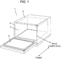
- FIG. 1 is a perspective view of the high frequency heating device with door 5 being opened according to the first exemplary embodiment of the present disclosure.
- FIG. 2 is a longitudinal sectional view of high frequency heating device 1 with door 5 being closed according to the first exemplary embodiment of the present disclosure.
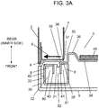
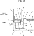
- FIGS. 3A to 3C are partial sectional views showing radio wave shielding portion 30 in the high frequency heating device according to the first exemplary embodiment of the present disclosure.
- FIG. 4 is a partial sectional perspective view of radio wave shielding portion 30 in the high frequency heating device according to the first exemplary embodiment of the present disclosure.
- FIGS. 1 is a perspective view of the high frequency heating device with door 5 being opened according to the first exemplary embodiment of the present disclosure.
- FIG. 2 is a longitudinal sectional view of high frequency heating device 1 with door 5 being closed according to the first exemplary embodiment of the present disclosure.
- FIG. 5 and 6 are partial sectional perspective views of radio wave shielding portion 30 in the high frequency heating device according to the first exemplary embodiment of the present disclosure.
- FIG. 7 is a diagram showing radio wave leakage characteristics of the high frequency heating device according to the first exemplary embodiment of the present disclosure.
- FIG. 8 is a partial sectional view of another radio wave shielding portion 30 in the high frequency heating device according to the first exemplary embodiment of the present disclosure.
- FIG. 9 is a partial sectional view of still another radio wave shielding portion 30 in the high frequency heating device according to the first exemplary embodiment of the present disclosure.
- a side where opening 4 of heating chamber 3 is formed is defined as a front side of high frequency heating device 1, and an inner side of heating chamber 3 is defined as a rear side (inner side) of high frequency heating device 1. Further, a right side of high frequency heating device 1 when high frequency heating device 1 is viewed from front is simply defined as a right side, and a left side of high frequency heating device 1 when high frequency heating device 1 is viewed from front is simply defined as a left side.
- high frequency heating device 1 will be described with reference to FIGS. 1 to 9 as appropriate.
- microwave 1 which is a representative example of the high frequency heating device has heating chamber 3 inside box-shaped outer box 2.
- Food which is a representative example of an object to be heated is accommodated in heating chamber 3.
- Opening 4 is formed in a front surface of heating chamber 3.
- Door 5 which opens and closes opening 4 is mounted to a front surface of outer box 2 in an openable manner.
- Opening peripheral portion 6 (hereinafter referred to as front plate 6) is provided between opening 4 and outer box 2 so as to face door 5 when door 5 is closed.
- a space is formed between an outer periphery of heating chamber 3 and outer box 2.
- Components for supplying high frequency waves such as high frequency wave generation unit 11 are housed in space 10 below heating chamber 3.
- High frequency wave generation unit 11 that is one of heating units for heating food includes components such as magnetron 12, wave guide 13, and rotating antenna 14.
- High frequency waves generated by magnetron 12 are transmitted through wave guide 13 and radiated to the inside of heating chamber 3.
- Rotating antenna 14 which is rotated for diffusing radio waves diffuses the high frequency waves radiated to heating chamber 3 throughout heating chamber 3. This configuration prevents standing waves of the high frequency waves from being fixed, thereby reducing uneven heating of food.
- Fan 15 for cooling magnetron 12 mainly during high frequency heating is provided near magnetron 12. Fan 15 supplies cooling air to magnetron 12.
- Upper heater 17 which is one of the components for heating food is provided in space 16 above heating chamber 3.
- Inner heater 19 which is one of the components for heating food is provided in space 18 behind heating chamber 3.
- Door 5 is configured to be opened and closed vertically.
- FIGS. 3A , 3B , and 3C are partial transverse sectional views of a front left part of microwave 1 with door 5 being closed.
- radio wave shielding portion 30 has open hole 31 formed in a surface facing front plate 6, and choke groove 32 that curves toward both heating chamber 3 and an opposite side to heating chamber 3, with respect to open hole 31.
- Choke groove 32 is formed by bonding recessed plate 33 (conductor) which is an electrical conductor and projecting plate 34 (conductor) which is an electrical conductor to each other.
- Projecting plate 34 has protrusion 36 which is formed near bonding portion 35 between both plates so as to protrude to the inside of heating chamber 3.
- a state of being near bonding portion 35 means herein that protrusion 36 is located within 30 mm from bonding portion 35, for example. It is more preferable that protrusion 36 is formed within 20 mm from bonding portion 35.
- Protrusion 36 is provided to form gap 37 with inner wall surface 7 of heating chamber 3 when door 5 is closed.
- An effective depth of choke groove 32 is set to be approximately a quarter of the wavelength of high frequency waves radiated to heating chamber 3.
- a direction of electric field of high frequency waves leaking to the outside of door 5 from the inside of heating chamber 3 is adjusted when high frequency waves propagate through gap 37 between protrusion 36 and inner wall surface 7 of heating chamber 3 and through gap 38 between front plate 6 and bonding portion 35.
- High frequency waves enter choke groove 32 through open hole 31.
- a phase of high frequency waves reflected in choke groove 32 and returning to open hole 31 is inverted at open hole 31 of choke groove 32. Therefore, an impedance becomes infinite, and thus, a leakage of high frequency waves can be prevented.
- an oscillation frequency of high frequency waves used in microwave 1 is 2450 MHz
- a wavelength is about 123 mm
- the effective depth of choke groove 32 is about 31 mm.
- choke groove 32 curves toward both heating chamber 3 and an opposite side to heating chamber 3, with respect to open hole 31, and thus, choke groove 32 has a plurality of depths. With this, a band effective for radio wave shielding performance in frequency characteristics can be widened.
- Plastic choke cover 42 is provided between recessed plate 33 and front plate 6. A choke structure is covered by plastic choke cover 42, so that intrusion of water, dust, debris, and the like into the choke structure can be prevented.
- the radio wave shielding performance varies due to a difference in dielectric constant between the inside of the choke structure and the intruding substance.
- choke cover 42 is necessary to improve reliability of the radio wave shielding performance. Further, choke cover 42 not only prevents a discharge phenomenon caused by intrusion of foreign matters but also improves appearance.
- the choke structure is often formed from a conductor plate. Therefore, choke cover 42 is provided to prevent a hand or fingers of a user from entering into choke groove 32 and in a slit and getting injured.
- Choke cover 42 corresponds to the shape of the choke structure, and may have a shape for closing the gap between door 5 and front plate 6.
- Choke cover 42 may be formed from a material absorbing high frequency waves and having less dielectric loss constant so as to hardly affect the radio wave shielding performance of the choke structure.
- choke cover 42 may be formed from resin such as polypropylene (PP), polyethylene terephthalate (PET), and polybutylene terephthalate (PBT).
- Inner glass 45 is disposed on a heating chamber 3 side of protrusion 36 for preventing entry of hot air, foreign matters, steam, or the like through a punched hole (not shown) formed in the center of projecting plate 34.
- the dielectric causes a loss of high frequency waves, whereby the leakage of radio waves can be reduced.
- the wavelength of high frequency waves is more compressed than in the air, and therefore, a phase change is greater in the dielectric when the high frequency waves propagate the same distance.
- the area of surfaces of front plate 6 and radio wave shielding portion 30 facing each other can be decreased, whereby the wall thickness between inner wall surface 7 of heating chamber 3 and outer box 2 can be reduced.
- the transmission speed of high frequency waves propagating through the air or in vacuum is equal to the speed of light.
- the transmission rate of high frequency waves transmitting through a dielectric is lower than the speed of light, and the wavelength is shorter than free space wavelength ⁇ .
- transmission rate Vd and wavelength ⁇ d of radio waves through the dielectric can be calculated from (Equation 1) and (Equation 2) described below.
- Specific dielectric constant ⁇ r and specific magnetic permeability ⁇ r of the dielectric are respectively a ratio relative to dielectric constant ⁇ in a vacuum and a ratio relative to magnetic permeability ⁇ in a vacuum.
- Magnetic permeability ⁇ of the dielectric is equal to magnetic permeability ⁇ , and thus, specific magnetic permeability ⁇ r becomes "1", and omitted in (Equation 2) below.
- wavelength ⁇ of radio waves is compressed in the dielectric, which provides an image in which a space is expanded in the dielectric as viewed from the radio waves. Therefore, when a portion of one propagating wave passes through the dielectric, and the rest of the wave propagates through the space, the synthetic wave of these waves propagates while bending and being refracted toward the dielectric.
- choke cover 42 formed from a dielectric
- open hole 31 at the inlet of choke groove 32 and slits 43 seem to be larger than the actual size as viewed from the high frequency waves.
- open hole 31 at the inlet of choke groove 32 and slits 43 can be decreased, whereby the strength of the choke structure can further be improved.
- Recessed plate 33 is formed by bending a plate five times in the same direction.
- Projecting plate 34 is molded by drawing press of L-shaped drawn portion 39 and protrusion 36. Recessed plate 33 and projecting plate 34 are bonded at bonding portion 35 by projection welding.
- Bonding portion 35 is disposed on a heating-chamber 3 center side of protrusion 36 and near protrusion 36, whereby the strength is improved. Due to protrusion 36 being formed into a box shape, the strength of projecting plate 34 can be dramatically improved as compared to a flat plate. Therefore, even if strain and stress are generated on bonding portion 35 due to welding, the deformation of projecting plate 34 such as warpage or waving can be significantly reduced. Accordingly, variation during assembly is prevented and appearance can be improved.
- choke groove 32 is formed such that a groove extending forward from open hole 31 curves toward both heating chamber 3 and an opposite side to heating chamber 3.
- first resonance space 80 and second resonance space 81 are formed in choke groove 32.
- First resonance space 80 and second resonance space 81 share common space 82 extending forward from open hole 31.
- First resonance space 80 and second resonance space 81 are regularly formed across slits 43 as shown in FIG. 4 .
- choke groove 32 can be expressed as follows. As shown in FIG. 3B , choke groove 32 is formed by combining first space 97 extending forward from open hole 31, second space 98 extending in a direction perpendicular to (or may be substantially perpendicular to) first space 97 so as to intersect first space 97, and third space 99 extending in a direction parallel to (or may be substantially parallel to) first space 97 so as to intersect second space 98. According to the study made by the inventors of the present invention, due to the presence of third space 99, a travel path of high frequency waves entering through open hole 31 can be easily separated into a first resonance space 80 side and a second resonance space 81 side.
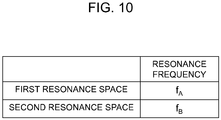
- First resonance space 80 and second resonance space 81 are set to have different resonance frequencies f A and f B . Therefore, the resonance characteristics of choke groove 32 are obtained by combining the resonance characteristics in first resonance space 80 and the resonance characteristics in second resonance space 81 (the obtained characteristics are referred to as synthesized resonance characteristics). Consequently, a frequency band in which radio waves can be shielded can be widened, whereby the radio wave shielding performance of radio wave shielding portion 30 can be improved.
- Examples of a method for setting a resonance frequency include changing the effective depth of choke groove 32 and inserting a dielectric into a part of choke groove 32.
- the distance between the inlet of gap 38 between door 5 and front plate 6 on the heating chamber 3 side and open hole 31 at the inlet of choke groove 32 is variable among the respective resonance spaces. Accordingly, the distance between the inlet of gap 38 between door 5 and front plate 6 on the heating chamber 3 side and open hole 31 at the inlet of choke groove 32 can be set to be a quarter of wavelength ⁇ with respect to a plurality of oscillation frequencies, whereby the frequency band in which radio waves can be shielded can be widened.
- the oscillation frequency of microwaves is limited to within a range from 2.4 GHz to 2.5 GHz according to the industry science medical (ISM) band.
- magnetron 12 is often used as the high frequency wave generation unit in microwave 1.
- Magnetron 12 generates high frequency waves with a variety of frequencies within a range from 2.4 GHz to 2.5 GHz.
- radio wave shielding portion 30 in the present exemplary embodiment has a plurality of resonance spaces 80 and 81, by which a frequency band in which radio waves can be shielded is widened. Thus, excellent radio wave shielding performance can be achieved.
- an electric field intensity in the resonance space is inversely proportional to the volume of the resonance space in choke groove 32. Therefore, when the volume of the resonance spaces as a whole is increased, the electric field intensity is lowered, which can prevent generation of sparks. Thus, safety can be improved.
- the wavelength of high frequency waves is compressed more in the dielectric than in the air, and therefore, the volume of the resonance spaces is apparently increased.
- the present exemplary embodiment only shows an example where there are two resonance spaces. However, the similar effect can also be obtained when there are three or more resonance spaces.
- Choke groove 32 has an effect of preventing a leakage of high frequency waves entering from a direction perpendicular to choke groove 32 by inverting the phase thereof.
- the radio wave shielding performance of choke groove 32 is relatively low for high frequency waves obliquely incident on choke groove 32.
- the effective depth of choke groove 32 is set to be a quarter of wavelength ⁇ for high frequency waves entering from a direction perpendicular to choke groove 32. Therefore, the propagation length of high frequency waves obliquely incident on choke groove 32 may not be equal to a quarter of wavelength ⁇ .
- slits 43 being regularly formed in choke groove 32 in the longitudinal direction, oblique incidence of high frequency waves on choke groove 32 can be converted into perpendicular incidence.
- slits 43 are formed at regular intervals in end 40 of recessed plate 33 and end 41 of projecting plate 34 to form a periodic structure as shown in FIG. 4 .
- the slits 43 are not necessarily formed at regular intervals. This is based on the following reason. Because the angle of incidence of high frequency waves entering choke groove 32 varies according to the distribution of standing waves inside heating chamber 3 around door 5, the best space between slits 43 for improving the radio wave shielding performance differs with location. Therefore, if there is a change in the shape of at least one of rotating antenna 14, wave guide 13, and the inside of heating chamber 3, which affects the distribution of standing waves in heating chamber 3, the space between slits 43 needs to be modified.
- FIG. 7 shows radio wave leakage characteristics for each gap of door 5 with the horizontal axis indicating the height of protrusion 36 and the vertical axis indicating leakage of radio waves.
- the leakage of radio waves is represented by a power density of leaked radio waves at a position 5 cm away from the gap between the door and the microwave main body when magnetron 12 of microwave 1 is driven.
- the technical standard of Electrical Appliances and Materials Safety Act specifies that the leakage of radio waves is 1 mW/cm 2 or less during operation with the maximum output with door 5 being closed, and that the leakage of radio waves is 5 mW/cm 2 or less in a state where door 5 is opened to a position just before the position where an oscillation stop device for magnetron 12 is operated.
- the characteristics with a 1 mm gap of door 5 in FIG. 7 indicate radio wave leakage performance with door 5 being closed, and the prescribed value of 1 mW/cm 2 or less in this state is satisfied, regardless of the height of protrusion 36.
- the height of protrusion 36 is preferably 2 mm or more in consideration of a margin.
- the characteristics with a 3 mm gap of door 5 indicate a state where door 5 is opened to the maximum position where magnetron 12 is operable, and the height of protrusion 36 for satisfying the prescribed value of 5 mW/cm 2 or less is 2 mm or more. In this case, a preferable height of protrusion 36 is 5 mm or more in consideration of a margin.
- the height of protrusion 36 is set to be 2 mm or more. Considering a margin, the height of protrusion 36 is set to be 5 mm or more.
- protrusion 36 the higher the protrusion 36 is, the less radio waves leaks. However, if the height exceeds 10 mm, it is highly likely that protrusion 36 interferes with an object to be heated or a container accommodated in heating chamber 3 upon closing door 5. Further, it is highly likely that protrusion 36 interferes with inner wall surface 7 of heating chamber 3 upon opening and closing door 5.
- the height of protrusion 36 is preferably 10 mm or less.
- this configuration can prevent protrusion 36 from interfering with an object to be heated which is to be accommodated inside heating chamber 3 and the inner wall surface of heating chamber 3. Moreover, this configuration can prevent deterioration in external appearance.
- the present exemplary embodiment shows the configuration in which two plates, recessed plate 33 and projecting plate 34, are bonded to each other at bonding portion 35.
- the present exemplary embodiment does not limit the number and shape of plates, the bonding method, and the like.
- projecting plate 34 may be composed of plate A 51 and plate B 52, and plate A 51 and plate B 52 may be bonded to each other at two portions which are bonding portion A 53 and bonding portion B 54.
- recessed plate 33 is opened at a bonding portion B 54 side with respect to choke groove 32, whereby a bending process or bonding process is facilitated.
- plate A 51 and plate B 52 are fixed at both outer bonding portion A 53 and inner bonding portion B 54 with respect to protrusion 36, whereby a rigid structure can be obtained.
- the strength of entire door 5 can be improved.
- the present exemplary embodiment shows the configuration where choke groove 32 curves toward both heating chamber 3 and the opposite side to heating chamber 3.
- recessed plate 33 may be bent four times so as not to form a dead end space at end 40.
- end 40 may be bent in the opposite direction or end 40 may not be bent.
- the shape of recessed plate 33 can be simplified, whereby low-cost production can be achieved.
- the width of front plate 6 can be decreased.
- microwave 1 which is a high frequency heating device according to the present exemplary embodiment includes: heating chamber 3 having opening 4; high frequency wave generation unit 11 that supplies high frequency waves to heating chamber 3; and door 5 that opens and closes opening 4 and has radio wave shielding portion 30 at a position facing opening peripheral portion 6.
- Radio wave shielding portion 30 is provided with open hole 31 and choke groove 32 on a surface facing front plate 6, wherein choke groove 32 is formed from conductors and has a plurality of dead end spaces 8.
- At least one slit 43 is formed each in both conductors provided across open hole 31.
- This configuration where slits 43 are formed on both facing surfaces of the conductors that constitute choke groove 32 can vary an impedance in the longitudinal direction of choke groove 32 more greatly, as compared to a configuration where slit 43 is formed in only one of the facing surfaces of the conductors constituting choke groove 32.
- the radio wave shielding performance of the choke structure can further be improved.
- high frequency heating device 1 Examples of high frequency heating device 1 according to the present exemplary embodiment will be described below.
- At least the radio wave shielding portion provided on one side has first synthesized resonance characteristics different from second synthesized resonance characteristics of the radio wave shielding portions provided on the other sides.
- "Being different” herein means that the first and second synthesized resonance characteristics do not exactly coincide with each other. That is, if the first and second synthesized resonance characteristics do not exactly coincide with each other, they are different from each other, although they partly coincide with each other.
- synthesized resonance characteristics of radio wave shielding portion 30A provided on lower side 202 of door 5 are different from synthesized resonance characteristics of radio wave shielding portions 30B provided on the other three sides (upper side 201, left side 203, and right side 204).
- Radio wave shielding portion 30A has two resonance spaces 80A and 81A having different resonance frequencies.
- radio wave shielding portion 30B also has two resonance spaces 80B and 81B having different resonance frequencies.
- radio wave shielding portions provided on one side of the door have a plurality of regions which is different from one another in synthesized resonance characteristics.
- radio wave shielding portion 30C has two resonance spaces 80C and 81C having different resonance frequencies. Further, radio wave shielding portion 30D also has two resonance spaces 80D and 81D having different resonance frequencies.
- synthesized resonance characteristics of radio wave shielding portion 30E provided on corner 205 of door 5 are different from synthesized resonance characteristics of radio wave shielding portion 30F provided on straight part 206 of door 5.
- Radio wave shielding portion 30E has two resonance spaces 80E and 81E having different resonance frequencies.
- radio wave shielding portion 30F also has two resonance spaces 80F and 81F having different resonance frequencies.
- cycle S (see FIG. 4 ) has regions which are different from one another in resonance characteristics.
- a high frequency heating device can be obtained which is provided with radio wave shielding portion 30 that can greatly attenuate high frequency waves in a wide variety of bands.
- Examples of a method for changing resonance frequencies in radio wave shielding portion 30 include changing the effective depth of choke groove 32, inserting a dielectric into a part of choke groove 32, and changing the length of one side of the conductors constituting radio wave shielding portion 30.
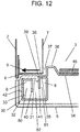
- FIGS. 12 and 13 are explanatory views of a high frequency heating device according to a second exemplary embodiment of the present disclosure. Now, specific configurations, operations, and effects of the present exemplary embodiment will be described below.
- FIG. 12 is a partial sectional view of a radio wave shielding portion in the high frequency heating device according to the second exemplary embodiment of the present disclosure.
- FIG. 13 is a partial sectional perspective view of the radio wave shielding portion in the high frequency heating device according to the second exemplary embodiment of the present disclosure.
- the overall configuration of the high frequency heating device in the present exemplary embodiment is similar to the configuration of microwave 1 shown in FIGS. 1 to 11 .
- microwave 1 which is the high frequency heating device in the present exemplary embodiment is configured such that slits 43 formed in both conductors provided across open hole 31 face each other in relation to direction 9 of leakage of high frequency waves. Slits 43 are not staggered in the direction of cycles.
- the distance between the conductors constituting choke groove 32 can be increased and the area of the facing surfaces of the conductors can be decreased at a location where slits 43 face each other, whereby variation in the impedance in the longitudinal direction of choke groove 32 can be significantly increased.
- the radio wave shielding performance of the choke structure can further be improved.
- projecting plate 34 constitutes one surface of door 5, and when door 5 is closed, projecting plate 34 constitutes a part of inner wall surface 7 of heating chamber 3.
- Recessed plate 33 may constitute one surface (inner wall surface 7 of heating chamber 3) of door 5. Projecting plate 34 is bonded to recessed plate 33 at bonding portion 35 to form choke groove 32.
- FIG. 13 illustrates the configuration where all slits 43 are not staggered in the direction of cycles.
- the present disclosure includes a configuration where at least one pair of slits 43 is not staggered in the direction of cycles.
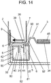
- FIGS. 14 to 18 are explanatory views of a high frequency heating device according to a third exemplary embodiment of the present disclosure.
- FIG. 14 is a partial sectional view of a radio wave shielding portion in the high frequency heating device according to the third exemplary embodiment of the present disclosure.
- FIG. 15 is a partial sectional perspective view of the radio wave shielding portion in the high frequency heating device according to the third exemplary embodiment of the present disclosure.
- FIG. 16 is a conceptual diagram for describing a propagation path of high frequency waves propagating to the radio wave shielding portion in the high frequency heating device in the third exemplary embodiment of the present disclosure.
- FIG. 17 is a partial sectional view of a radio wave shielding portion in the high frequency heating device according to the third exemplary embodiment of the present disclosure.
- FIG. 18 is a conceptual diagram showing a shape of an inner surface of a heating chamber relative to a shape of a protrusion in the third exemplary embodiment of the present disclosure.
- the overall configuration of the high frequency heating device in the present exemplary embodiment is similar to the configuration of microwave 1 shown in FIGS. 1 to 13 .
- protrusion 91 The configuration of protrusion 91 will be described. As shown in FIGS. 14 to 18 , in radio wave shielding portion 90 in the present exemplary embodiment, protrusion facing surface 92 of protrusion 91 facing inner wall surface 7 of heating chamber 3 is inclined to heating chamber 3. The following effects can be obtained by forming gap 93 between inner wall surface 7 of heating chamber 3 and protrusion facing surface 92 into a wedge shape.
- protrusion 91 located on a rotating end (upper side if door 5 is a front open door) upon opening and closing door 5 follows a trajectory to get close to bonding portion 35.
- gap 93 between inner wall surface 7 of heating chamber 3 and protrusion facing surface 92 is generally set to be large.
- protrusion facing surface 92 is inclined to heating chamber 3. Therefore, interference between protrusion 91 and inner wall surface 7 of heating chamber 3 can be avoided without increasing the volume of gap 93.
- end face 94 of inner wall surface 7 of heating chamber 3 facing inclined protrusion facing surface 92 may be inclined so as to form constant (may be substantially constant) gap 95 with protrusion facing surface 92. According to this configuration, the following effects can be obtained.
- predetermined space X is formed so that protrusion 91 and inner wall surface 7 of heating chamber 3 do not interfere with each other even if the relative position between protrusion 91 and inner wall surface 7 of heating chamber 3 varies in a direction parallel to the surface of front plate 6 due to variation in size or mounting variation.
- Protrusion facing surface 92 and end face 94 are inclined parallel to (or may be substantially parallel to) each other, and therefore, width H of constant gap 95 with respect to protrusion facing surface 92 is smaller than space X according to inclination angle ⁇ . As described above, width H of gap 95 can be decreased, whereby attenuation of propagating high frequency waves can be increased.
- slits 43 in the choke structure is as stated in the first exemplary embodiment.
- An advantage will be described below of the configuration where slits 43 are formed such that both conductors provided across open hole 31 so as to constitute the choke structure have at least one portion where both conductors do not face each other.
- High frequency waves propagate while generating an electric field between the conductors facing each other.
- slits 43 are formed in choke groove 32, the propagation in the direction of cycles can be reduced, because the electric field is not generated in slits 43.
- the conductors partly face each other or when an electric field is generated due to another conductor being present near the propagation path in the direction of cycles, the effect of slits 43 is reduced.
- the amount of high frequency waves propagating in the direction of cycles is in proportion to the area of the facing surfaces of the conductors. In view of this, when slits 43 are formed so that the conductors do not face each other at all, the high frequency waves to propagate in the direction of cycles can be effectively reduced.
- slits 43 are formed in radio wave shielding portion 90 so that both conductors provided across open hole 31 have at least one portion where both conductors do not face each other.
- the present exemplary embodiment is different from the second exemplary embodiment in that there is a portion where the conductors do not face each other at all on one side of the conductors constituting the choke structure.
- the present exemplary embodiment is the same as the second exemplary embodiment in that there are portions where the conductors face each other even a little on one side.
- projecting plate 34 constitutes one surface of door 5, and when door 5 is closed, projecting plate 34 constitutes a part of the inner wall surface of heating chamber 3.
- the configuration is not limited thereto.
- Recessed plate 33 may constitute one surface of door 5, and recessed plate 33 may constitute inner wall surface 7 of heating chamber 3. Projecting plate 34 may be bonded to recessed plate 33 at bonding portion 35 to form choke groove 32.
- all slits 43 formed in both conductors provided across open hole 31 are formed such that the conductors do not face each other.
- the present disclosure includes a configuration where both conductors have at least one portion where they do not face each other at all.
- the resonance frequency of radio wave shielding portion 90 may be varied by changing the length of at least one side of conductors 33 and 34 constituting radio wave shielding portion 90.
- step 95 is formed on a surface facing opening peripheral portion 6.
- plastic choke cover 42 is provided on choke groove 32 so as to prevent fingers from entering choke groove 32 and getting injured, step 95 is not formed on the surface facing opening peripheral portion 6. Therefore, the appearance can be improved, cleaning performance can be improved, and a packing for preventing intrusion of water through a gap between choke cover 42 and choke groove 32 can be formed to have a simple structure.
- the high frequency heating device according to the present disclosure is applicable not only to single-function microwaves having only a high frequency heating function but also microwaves having an oven function or grilling function and microwaves having a steam function.
- the high frequency heating device according to the present disclosure is widely applicable to domestic and industrial microwaves.
Description
- The present disclosure relates to a high frequency heating device such as a microwave, and more particularly to a high frequency heating device provided with a radio wave shielding portion that shields radio waves (particularly, microwaves which are high frequency waves) that are going to leak to an outside from between a heating chamber and a door.
- Conventionally, as a most basic concept regarding a radio wave shielding portion used for a microwave, a quarter-wave impedance inversion method in which a choke groove is formed in a door has been proposed.
- First, a first conventional example will be described with reference to the drawings.
FIG. 19 is a perspective view showing an external appearance ofmicrowave 101 which is a conventional high frequency heating device.FIG. 20 is a sectional view, along line 20-20, of a radio wave shielding portion provided betweenheating chamber 103 anddoor 102 ofmicrowave 101 shown inFIG. 19 . - High frequency waves generated inside
heating chamber 103 provided inmicrowave 101 propagate from right to left (z direction) inFIG. 20 and are going to leak throughgap 106 betweendoor 102 and openingperipheral portion 105 which is located on an outer periphery of opening 104 ofheating chamber 103 so as to facedoor 102. Inconventional microwave 101,choke groove 108 formed fromconductor 107 is provided indoor 102, and length L ofchoke groove 108 is set to be a quarter (about 31 mm) of wavelength λ of a frequency to be used. With this, impedance Zin seen fromopen hole 109 at an inlet ofchoke groove 108 toward the inside ofchoke groove 108 becomes infinite, so that the high frequency waves in the z direction attenuate (for example, see PTL 1). - In the conventional configuration described above,
open hole 109 at the inlet ofchoke groove 108 andgap 106 are disposed to face openingperipheral portion 105, and this configuration generally provides an advantage to reduce the width (z direction) of openingperipheral portion 105. However, due to length L ofchoke groove 108 being large, it is difficult to reduce the thickness (y direction) ofdoor 102, which prevents reduction in size ofmicrowave 101. - Next, second and third conventional examples will be described. PTL 1 proposes radio wave shielding portions illustrated in
FIG. 21 (second conventional example) andFIG. 22 (third conventional example) as a configuration for reducing length L ofchoke groove 108. The proposed configuration is such thatchoke groove 108 is curved to reduce length L ofchoke groove 108, that is, to makechoke groove 108 compact, while maintaining radio wave shielding performance. - Note that the configurations shown in
FIGS. 21 and 22 are similar to the configuration shown inFIG. 20 in a theory for shielding radio waves in which impedance Zin seen fromopen hole 109 at the inlet ofchoke groove 108 toward the inside ofchoke groove 108 is set to be infinite to attenuate high frequency waves in the z direction. - In the configuration shown in
FIG. 21 ,single conductor 110 is bent five times to obtain deadend choke groove 108. In this configuration,choke groove 108 can be formed only by bendingsingle conductor 110. Therefore, this configuration is well suited to mass production, and thus, widely applied. - In the configuration shown in
FIG. 22 , two conductors, which areconductor 111 having a recessed shape andconductor 112 having an L shape, are joined to each other to formchoke groove 108 curving towardheating chamber 103. Similar to the configuration shown inFIG. 20 , this configuration hasopen hole 109 at the inlet ofchoke groove 108 andgap 106 which are disposed to face openingperipheral portion 105, thereby being capable of reducing the width (z direction) of openingperipheral portion 105. - Further, as shown in
FIG. 23 , a microwave has been proposed in which high frequencywave propagation path 118 defined bygap 106 between openingperipheral portion 105 anddoor 102 is formed on aninner wall surface 117 side ofheating chamber 103 to improve radio wave shielding performance (seePTL 2, for example). - PTL 2 proposes
microwave 101 havingdoor 102 which is provided with, inside of an outer periphery,choke groove 114 formed by bendingsingle conductor 113 four times as shown inFIG. 23 .Protrusion 116 protruding towardheating chamber 103 is formed on outer peripheryinner wall 115 on aheating chamber 103 side ofdoor 102. High frequencywave propagation path 118 is formed which attenuates high frequency waves byprotrusion 116 andinner wall surface 117 ofheating chamber 103 before the high frequency waves enterchoke groove 114, withdoor 102 being closed. - A phase of high frequency
waves entering gap 106 between openingperipheral portion 105 anddoor 102 fromheating chamber 103 is changed during propagation throughgap 106. Then, the phase is inverted at a position where the high frequency waves advance by a quarter of wavelength λ. - Therefore, as the distance between
open hole 109 at the inlet ofchoke groove 114 and the inlet ofgap 106 between openingperipheral portion 105 anddoor 102 on theheating chamber 103 side is closer to a quarter of wavelength λ, an impedance atend 150 of high frequencywave propagation path 118 nearheating chamber 103 becomes closer to short-circuit. As a result, high frequencywaves entering gap 106 between openingperipheral portion 105 anddoor 102 can be reduced. - With this configuration, it is unnecessary to rely only on
choke groove 114 for the radio wave shielding performance, and a leakage of radio waves can be reduced. - In addition,
PTL 3 and PTL 4 propose a microwave in which high frequencywave propagation path 118 is formed ininner wall surface 117 of the heating chamber to reduce the width of openingperipheral portion 105. With this configuration, a wall thickness ofmicrowave 101 can be reduced. Thus, it is possible to downsize a main body with the capacity ofheating chamber 103 being unchanged, or to increase capacity ofheating chamber 103 with the size of the main body being unchanged. - In choke structures disclosed in
PTL 1 toPTL 4, slits are formed at regular intervals on either of facing surfaces of the conductors constituting the choke groove. Shapes, positions, and other factors of the slits are not described in detail inPTL 1 toPTL 4. The documentWO2017/154713 A1 is a document pursuant to Article 54(3) EPC and discloses a high frequency device according to the preamble ofclaim 1. - However, the conventional configuration where slits are formed at regular intervals on either of facing surfaces of the conductors constituting the choke groove may be unable to sufficiently reduce propagation of high frequency waves in an x direction (longitudinal direction). In addition, the formation of slits may deteriorate mechanical strength of the choke structure.
- In general, a high frequency wave generating device in a microwave often uses a magnetron. The magnetron generates high frequency waves with a variety of frequencies within a range from 2.4 GHz to 2.5 GHz.
- Therefore, when the radio wave shielding performance of the choke structure only provides a narrow frequency band in which radio waves can be sufficiently shielded, a frequency band may be generated where high frequency waves generated from the magnetron cannot sufficiently be shielded. Further, a distribution of an oscillation frequency of high frequency waves generated from the magnetron varies depending on a physical value of an object to be heated, a placement position of the object to be heated, a shape of an inside of the heating chamber, and other factors. From the above, the choke structure needs to have radio wave shielding performance for greatly attenuating high frequency waves in a wide variety of frequency bands.
- Notably, Unexamined
Japanese Patent Publication No. S58-066285 Japanese Patent Publication No. S58-066287 Japanese Patent Publication No. S58-066288 Japanese Patent Publication No. S58-150292 Japanese Patent Publication No. S58-194290 Japanese Patent Publication No. S58-201289 Japanese Patent Publication No. S58-201290 -
- PTL 1: Unexamined
Japanese Patent Publication No. H06-132078 - PTL 2:
Japanese Patent No. 4647548 - PTL 3: Unexamined
Japanese Patent Publication No. S62-5595 - PTL 4: Examined
Japanese Utility Model Publication No. S51-9083 - PTL 5: Unexamined
Japanese Patent Publication No. S58-066285 - PTL 6: Unexamined
Japanese Patent Publication No. S58-066287 - PTL 7: Unexamined
Japanese Patent Publication No. S58-066288 - PTL 8: Unexamined
Japanese Patent Publication No. S58-150292 - PTL 9: Unexamined
Japanese Patent Publication No. S58-194290 - PTL 10: Unexamined
Japanese Patent Publication No. S58-201289 - PTL 11: Unexamined
Japanese Patent Publication No. S58-201290 - The present disclosure addresses the foregoing problems, and aims to provide a high frequency heating device having high radio wave shielding performance.
- In order to address the above-mentioned conventional problems, a high frequency heating device according to the present disclosure includes: a heating chamber having an opening; an opening peripheral portion provided at a peripheral edge of the opening; a high frequency wave generation unit that supplies high frequency waves to the heating chamber; and a door that covers the opening in an openable manner and has a radio wave shielding portion at a position facing the opening peripheral portion. The radio wave shielding portion is provided with an open hole provided so as to face the opening peripheral portion, and a choke groove formed from a plurality of conductors. The choke groove has a first resonance space having a first resonance frequency, and a second resonance space having a second resonance frequency different from the first resonance frequency, charaterised in that from among the radio wave shielding portions provided on four sides of an entire perimeter of the door(5), the radio wave shielding portion provided on a lower side of the door(5)has synthesized resonance characteristics different from synthesized resonance characteristics of the radio wave shielding portions provided on the other three sides.
- Accordingly, radio wave shielding performance can be improved.
- According to the configuration in the present disclosure, a high frequency heating device having high radio wave shielding performance can be provided.
-
-
FIG. 1 is a perspective view of a high frequency heating device with a door being opened according to a first exemplary embodiment of the present disclosure. -
FIG. 2 is a longitudinal sectional view of the high frequency heating device with the door being closed according to the first exemplary embodiment of the present disclosure. -
FIG. 3A is a partial sectional view of a radio wave shielding portion in the high frequency heating device according to the first exemplary embodiment of the present invention. -
FIG. 3B is a partial sectional view of the radio wave shielding portion in the high frequency heating device according to the first exemplary embodiment of the present invention. -
FIG. 3C is a partial sectional view of the radio wave shielding portion in the high frequency heating device according to the first exemplary embodiment of the present invention. -
FIG. 4 is a partial sectional perspective view of the radio wave shielding portion in the high frequency heating device according to the first exemplary embodiment of the present disclosure. -
FIG. 5 is a partial sectional perspective view of a radio wave shielding portion in the high frequency heating device according to the first exemplary embodiment of the present disclosure. -
FIG. 6 is a partial sectional perspective view of a radio wave shielding portion in the high frequency heating device according to the first exemplary embodiment of the present disclosure. -
FIG. 7 is a diagram showing radio wave leakage characteristics of the high frequency heating device according to the first exemplary embodiment of the present disclosure. -
FIG. 8 is a partial sectional view of another radio wave shielding portion in the high frequency heating device according to the first exemplary embodiment of the present disclosure. -
FIG. 9 is a partial sectional view of still another radio wave shielding portion in the high frequency heating device according to the first exemplary embodiment of the present disclosure. -
FIG. 10 is a diagram for describing resonance characteristics of a radio wave shielding portion in the high frequency heating device according to the first exemplary embodiment of the present disclosure. -
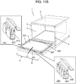
FIG. 11A is a conceptual view for describing radio wave shielding portions in a high frequency heating device according to Example 1 in the present disclosure. -
FIG. 11B is a conceptual view for describing radio wave shielding portions in a high frequency heating device according to Example 2 in the present disclosure. -
FIG. 11C is a conceptual view for describing radio wave shielding portions in a high frequency heating device according to Example 3 in the present disclosure. -
FIG. 12 is a partial sectional view of a radio wave shielding portion in a high frequency heating device according to a second exemplary embodiment of the present disclosure. -
FIG. 13 is a partial sectional perspective view of the radio wave shielding portion in the high frequency heating device according to the second exemplary embodiment of the present disclosure. -
FIG. 14 is a partial sectional view of a radio wave shielding portion in a high frequency heating device according to a third exemplary embodiment of the present disclosure. -
FIG. 15 is a partial sectional perspective view of the radio wave shielding portion in the high frequency heating device according to the third exemplary embodiment of the present disclosure. -
FIG. 16 is a conceptual diagram for describing a propagation path of high frequency waves propagating to the radio wave shielding portion in the high frequency heating device in the third exemplary embodiment of the present disclosure. -
FIG. 17 is a partial sectional view of a radio wave shielding portion in the high frequency heating device according to the third exemplary embodiment of the present disclosure. -
FIG. 18 is a conceptual diagram showing a shape of an inner surface of a heating chamber relative to a shape of a protrusion in the third exemplary embodiment of the present disclosure. -
FIG. 19 is a perspective view showing an external appearance of a high frequency heating device according to a first conventional example. -
FIG. 20 is a sectional view of a radio wave shielding portion, along line 20-20, in the high frequency heating device in the first conventional example. -
FIG. 21 is a partial sectional view of a radio wave shielding portion in a high frequency heating device according to a second conventional example. -
FIG. 22 is a partial sectional view of a radio wave shielding portion in a high frequency heating device according to a third conventional example. -
FIG. 23 is a partial sectional view of a radio wave shielding portion in a high frequency heating device according to a fourth conventional example. - A high frequency heating device according to the present disclosure includes: a heating chamber having an opening; an opening peripheral portion provided at a peripheral edge of the opening; a high frequency wave generation unit that supplies high frequency waves to the heating chamber; and a door that covers the opening in an openable manner and has a radio wave shielding portion at a position facing the opening peripheral portion. The radio wave shielding portion is provided with an open hole provided so as to face the opening peripheral portion, and a choke groove formed from a plurality of conductors. The choke groove has a first resonance space having a first resonance frequency, and a second resonance space having a second resonance frequency different from the first resonance frequency.
- The choke groove may curve toward both the heating chamber and an opposite side to the heating chamber, across the open hole.
- From among radio wave shielding portions provided on four sides of the entire perimeter of the door, at least the radio wave shielding portion provided on one side may have synthesized resonance characteristics different from synthesized resonance characteristics of the radio wave shielding portions provided on the other sides.
- The radio wave shielding portion provided on the lower side of the door may have synthesized resonance characteristics different from synthesized resonance characteristics of the radio wave shielding portions provided on the other three sides.
- The radio wave shielding portion provided on one side of the door may have a plurality of regions which is different from one another in synthesized resonance characteristics.
- The radio wave shielding portion provided on a corner of the door may have synthesized resonance characteristics different from synthesized resonance characteristics of the radio wave shielding portion provided on a straight part.
- The synthesized resonance characteristics of the radio wave shielding portion may be varied by changing the length of at least one side of the conductors constituting the radio wave shielding portion.
- Preferable exemplary embodiments of the high frequency heating device according to the present disclosure will be described below with reference to the accompanying drawings. In the following exemplary embodiments, the high frequency heating device is a microwave. However, the microwave is only an example of the high frequency heating device. The high frequency heating device according to the present disclosure is not limited to a microwave, and may include a high frequency heating device such as a heating device using induction heating, a garbage disposal, or a semiconductor manufacturing device.
- The present disclosure is not limited to specific configurations in the following exemplary embodiments, and a configuration based on a similar technical concept is included in the present disclosure.
-
FIGS. 1 to 9 are diagrams for describing a high frequency heating device according to a first exemplary embodiment of the present disclosure.FIG. 1 is a perspective view of the high frequency heating device withdoor 5 being opened according to the first exemplary embodiment of the present disclosure.FIG. 2 is a longitudinal sectional view of highfrequency heating device 1 withdoor 5 being closed according to the first exemplary embodiment of the present disclosure.FIGS. 3A to 3C are partial sectional views showing radiowave shielding portion 30 in the high frequency heating device according to the first exemplary embodiment of the present disclosure.FIG. 4 is a partial sectional perspective view of radiowave shielding portion 30 in the high frequency heating device according to the first exemplary embodiment of the present disclosure.FIGS. 5 and6 are partial sectional perspective views of radiowave shielding portion 30 in the high frequency heating device according to the first exemplary embodiment of the present disclosure.FIG. 7 is a diagram showing radio wave leakage characteristics of the high frequency heating device according to the first exemplary embodiment of the present disclosure.FIG. 8 is a partial sectional view of another radiowave shielding portion 30 in the high frequency heating device according to the first exemplary embodiment of the present disclosure.FIG. 9 is a partial sectional view of still another radiowave shielding portion 30 in the high frequency heating device according to the first exemplary embodiment of the present disclosure. - In the following description, a side where
opening 4 ofheating chamber 3 is formed is defined as a front side of highfrequency heating device 1, and an inner side ofheating chamber 3 is defined as a rear side (inner side) of highfrequency heating device 1. Further, a right side of highfrequency heating device 1 when highfrequency heating device 1 is viewed from front is simply defined as a right side, and a left side of highfrequency heating device 1 when highfrequency heating device 1 is viewed from front is simply defined as a left side. - Hereinafter, high
frequency heating device 1 will be described with reference toFIGS. 1 to 9 as appropriate. - As shown in
FIG. 1 ,microwave 1 which is a representative example of the high frequency heating device hasheating chamber 3 inside box-shapedouter box 2. Food which is a representative example of an object to be heated is accommodated inheating chamber 3.Opening 4 is formed in a front surface ofheating chamber 3.Door 5 which opens and closesopening 4 is mounted to a front surface ofouter box 2 in an openable manner. - Opening peripheral portion 6 (hereinafter referred to as front plate 6) is provided between
opening 4 andouter box 2 so as to facedoor 5 whendoor 5 is closed. - As shown in
FIG. 2 , a space is formed between an outer periphery ofheating chamber 3 andouter box 2. Components for supplying high frequency waves such as high frequencywave generation unit 11 are housed inspace 10 belowheating chamber 3. High frequencywave generation unit 11 that is one of heating units for heating food includes components such asmagnetron 12,wave guide 13, and rotatingantenna 14. High frequency waves generated bymagnetron 12 are transmitted throughwave guide 13 and radiated to the inside ofheating chamber 3. Rotatingantenna 14 which is rotated for diffusing radio waves diffuses the high frequency waves radiated toheating chamber 3 throughoutheating chamber 3. This configuration prevents standing waves of the high frequency waves from being fixed, thereby reducing uneven heating of food.Fan 15 for coolingmagnetron 12 mainly during high frequency heating is provided nearmagnetron 12.Fan 15 supplies cooling air tomagnetron 12. -
Upper heater 17 which is one of the components for heating food is provided inspace 16 aboveheating chamber 3.Inner heater 19 which is one of the components for heating food is provided inspace 18 behindheating chamber 3. -
Door 5 is configured to be opened and closed vertically. - Next, a configuration of radio
wave shielding portion 30 provided todoor 5 at a position facingfront plate 6 will be described with reference toFIGS. 3A ,3B , and3C .FIGS. 3A ,3B , and3C are partial transverse sectional views of a front left part ofmicrowave 1 withdoor 5 being closed. - In
FIGS. 3A ,3B , and3C , radiowave shielding portion 30 hasopen hole 31 formed in a surface facingfront plate 6, and chokegroove 32 that curves toward bothheating chamber 3 and an opposite side toheating chamber 3, with respect to openhole 31. Chokegroove 32 is formed by bonding recessed plate 33 (conductor) which is an electrical conductor and projecting plate 34 (conductor) which is an electrical conductor to each other. Projectingplate 34 hasprotrusion 36 which is formed nearbonding portion 35 between both plates so as to protrude to the inside ofheating chamber 3. A state of being nearbonding portion 35 means herein thatprotrusion 36 is located within 30 mm from bondingportion 35, for example. It is more preferable thatprotrusion 36 is formed within 20 mm from bondingportion 35. -
Protrusion 36 is provided to formgap 37 withinner wall surface 7 ofheating chamber 3 whendoor 5 is closed. An effective depth ofchoke groove 32 is set to be approximately a quarter of the wavelength of high frequency waves radiated toheating chamber 3. - A direction of electric field of high frequency waves leaking to the outside of
door 5 from the inside ofheating chamber 3 is adjusted when high frequency waves propagate throughgap 37 betweenprotrusion 36 andinner wall surface 7 ofheating chamber 3 and throughgap 38 betweenfront plate 6 andbonding portion 35. High frequency waves enterchoke groove 32 throughopen hole 31. A phase of high frequency waves reflected inchoke groove 32 and returning to openhole 31 is inverted atopen hole 31 ofchoke groove 32. Therefore, an impedance becomes infinite, and thus, a leakage of high frequency waves can be prevented. For example, when an oscillation frequency of high frequency waves used inmicrowave 1 is 2450 MHz, a wavelength is about 123 mm, and therefore, the effective depth ofchoke groove 32 is about 31 mm. - In the present exemplary embodiment, choke
groove 32 curves toward bothheating chamber 3 and an opposite side toheating chamber 3, with respect to openhole 31, and thus, chokegroove 32 has a plurality of depths. With this, a band effective for radio wave shielding performance in frequency characteristics can be widened. - Further, when a surface leading to end 40 of recessed
plate 33 and a surface leading to end 41 of projectingplate 34 inchoke groove 32 face each other with a predetermined space therebetween, the direction of electric field of high frequency waves between both surfaces is adjusted. With this, high frequency waves can be smoothly transmitted intochoke groove 32. Thus, a leakage of radio waves can be reduced. - In addition, high frequency waves attenuate while propagating through
gap 37 betweenprotrusion 36 andinner wall surface 7 ofheating chamber 3, and therefore, a propagation length ofgap 38 betweenfront plate 6 andbonding portion 35 can be decreased. Furthermore, due to chokegroove 32 curving towardheating chamber 3, an area of radiowave shielding portion 30 facingfront plate 6 can be decreased. Thus, a wall thickness betweeninner wall surface 7 ofheating chamber 3 andouter box 2 can be significantly reduced. - While high frequency
waves entering gap 38 betweenfront plate 6 anddoor 5 fromheating chamber 3 propagate throughgap 38, the phase is changed, and inverted when the high frequency waves advance by a quarter of wavelength λ. - Therefore, as the distance between
open hole 31 at the inlet ofchoke groove 32 and the inlet ofgap 38 betweenfront plate 6 anddoor 5 on theheating chamber 3 side is closer to a quarter of wavelength λ, an impedance atinlet 50 ofgap 38 nearheating chamber 3 becomes closer to short-circuit. With this configuration, high frequencywaves entering gap 38 betweenfront plate 6 anddoor 5 can be reduced. Accordingly, it is unnecessary to rely only onchoke groove 32 for the radio wave shielding performance, and a leakage of radio waves can be reduced. - Plastic choke cover 42 is provided between recessed
plate 33 andfront plate 6. A choke structure is covered byplastic choke cover 42, so that intrusion of water, dust, debris, and the like into the choke structure can be prevented. When water intrudes into the choke structure, the radio wave shielding performance varies due to a difference in dielectric constant between the inside of the choke structure and the intruding substance. In view of this, chokecover 42 is necessary to improve reliability of the radio wave shielding performance. Further, chokecover 42 not only prevents a discharge phenomenon caused by intrusion of foreign matters but also improves appearance. - The choke structure is often formed from a conductor plate. Therefore, choke
cover 42 is provided to prevent a hand or fingers of a user from entering intochoke groove 32 and in a slit and getting injured. -
Choke cover 42 corresponds to the shape of the choke structure, and may have a shape for closing the gap betweendoor 5 andfront plate 6.Choke cover 42 may be formed from a material absorbing high frequency waves and having less dielectric loss constant so as to hardly affect the radio wave shielding performance of the choke structure. For example, chokecover 42 may be formed from resin such as polypropylene (PP), polyethylene terephthalate (PET), and polybutylene terephthalate (PBT). -
Inner glass 45 is disposed on aheating chamber 3 side ofprotrusion 36 for preventing entry of hot air, foreign matters, steam, or the like through a punched hole (not shown) formed in the center of projectingplate 34. - Further, in the configuration where a dielectric such as
plastic choke cover 42 is provided between recessedplate 33 andfront plate 6, the dielectric causes a loss of high frequency waves, whereby the leakage of radio waves can be reduced. Moreover, in the dielectric, the wavelength of high frequency waves is more compressed than in the air, and therefore, a phase change is greater in the dielectric when the high frequency waves propagate the same distance. Thus, the area of surfaces offront plate 6 and radiowave shielding portion 30 facing each other can be decreased, whereby the wall thickness betweeninner wall surface 7 ofheating chamber 3 andouter box 2 can be reduced. - The wavelength compression in the dielectric will be described in detail below.
- The transmission speed of high frequency waves propagating through the air or in vacuum is equal to the speed of light. The transmission rate of high frequency waves transmitting through a dielectric is lower than the speed of light, and the wavelength is shorter than free space wavelength λο.
- When the speed of light is defined as Vc (3 × 1011 mm/s) and the specific dielectric constant of the dielectric is defined as εr, transmission rate Vd and wavelength λd of radio waves through the dielectric can be calculated from (Equation 1) and (Equation 2) described below.
- Specific dielectric constant εr and specific magnetic permeability µr of the dielectric are respectively a ratio relative to dielectric constant εο in a vacuum and a ratio relative to magnetic permeability µο in a vacuum. Magnetic permeability µ of the dielectric is equal to magnetic permeability µο, and thus, specific magnetic permeability µr becomes "1", and omitted in (Equation 2) below.


- Specifically, wavelength λ of radio waves is compressed in the dielectric, which provides an image in which a space is expanded in the dielectric as viewed from the radio waves. Therefore, when a portion of one propagating wave passes through the dielectric, and the rest of the wave propagates through the space, the synthetic wave of these waves propagates while bending and being refracted toward the dielectric.
- Therefore, when choke cover 42 (formed from a dielectric) is mounted in
open hole 31 at the inlet ofchoke groove 32 and inslits 43, the wavelength of high frequency waves is compressed inchoke cover 42. Thus,open hole 31 at the inlet ofchoke groove 32 and slits 43 seem to be larger than the actual size as viewed from the high frequency waves. - Accordingly, when choke cover 42 is provided,
open hole 31 at the inlet ofchoke groove 32 and slits 43 can be decreased, whereby the strength of the choke structure can further be improved. - Recessed
plate 33 is formed by bending a plate five times in the same direction. Projectingplate 34 is molded by drawing press of L-shaped drawnportion 39 andprotrusion 36. Recessedplate 33 and projectingplate 34 are bonded atbonding portion 35 by projection welding. -
Bonding portion 35 is disposed on a heating-chamber 3 center side ofprotrusion 36 and nearprotrusion 36, whereby the strength is improved. Due toprotrusion 36 being formed into a box shape, the strength of projectingplate 34 can be dramatically improved as compared to a flat plate. Therefore, even if strain and stress are generated onbonding portion 35 due to welding, the deformation of projectingplate 34 such as warpage or waving can be significantly reduced. Accordingly, variation during assembly is prevented and appearance can be improved. - Next, a choke structure having a plurality of resonance spaces is discussed.
- As shown in
FIG. 3A , chokegroove 32 is formed such that a groove extending forward fromopen hole 31 curves toward bothheating chamber 3 and an opposite side toheating chamber 3. According to this configuration,first resonance space 80 andsecond resonance space 81 are formed inchoke groove 32.First resonance space 80 andsecond resonance space 81 sharecommon space 82 extending forward fromopen hole 31.First resonance space 80 andsecond resonance space 81 are regularly formed acrossslits 43 as shown inFIG. 4 . - The configuration of
choke groove 32 can be expressed as follows. As shown inFIG. 3B , chokegroove 32 is formed by combiningfirst space 97 extending forward fromopen hole 31,second space 98 extending in a direction perpendicular to (or may be substantially perpendicular to)first space 97 so as to intersectfirst space 97, andthird space 99 extending in a direction parallel to (or may be substantially parallel to)first space 97 so as to intersectsecond space 98. According to the study made by the inventors of the present invention, due to the presence ofthird space 99, a travel path of high frequency waves entering throughopen hole 31 can be easily separated into afirst resonance space 80 side and asecond resonance space 81 side. - Subsequently, resonance characteristics of
choke groove 32 will be described with reference toFIG. 10 .First resonance space 80 andsecond resonance space 81 are set to have different resonance frequencies fA and fB. Therefore, the resonance characteristics ofchoke groove 32 are obtained by combining the resonance characteristics infirst resonance space 80 and the resonance characteristics in second resonance space 81 (the obtained characteristics are referred to as synthesized resonance characteristics). Consequently, a frequency band in which radio waves can be shielded can be widened, whereby the radio wave shielding performance of radiowave shielding portion 30 can be improved. - Examples of a method for setting a resonance frequency include changing the effective depth of
choke groove 32 and inserting a dielectric into a part ofchoke groove 32. - Further, due to the configuration where a plurality of resonance spaces is formed, the distance between the inlet of
gap 38 betweendoor 5 andfront plate 6 on theheating chamber 3 side andopen hole 31 at the inlet ofchoke groove 32 is variable among the respective resonance spaces. Accordingly, the distance between the inlet ofgap 38 betweendoor 5 andfront plate 6 on theheating chamber 3 side andopen hole 31 at the inlet ofchoke groove 32 can be set to be a quarter of wavelength λ with respect to a plurality of oscillation frequencies, whereby the frequency band in which radio waves can be shielded can be widened. - The oscillation frequency of microwaves is limited to within a range from 2.4 GHz to 2.5 GHz according to the industry science medical (ISM) band. In general,
magnetron 12 is often used as the high frequency wave generation unit inmicrowave 1.Magnetron 12 generates high frequency waves with a variety of frequencies within a range from 2.4 GHz to 2.5 GHz. - Therefore, when the radio wave shielding performance of the choke structure only provides a narrow frequency band in which radio waves can be sufficiently shielded, a frequency band may be generated in which high frequency waves generated from
magnetron 12 cannot sufficiently be shielded. Further, the distribution of oscillation frequencies of high frequency waves generated frommagnetron 12 varies depending on a physical value of an object to be heated, a placement position of the object to be heated, a shape of the inside ofheating chamber 3, and other factors. As described above, radiowave shielding portion 30 in the present exemplary embodiment has a plurality ofresonance spaces - Next, an increase in volume of the resonance spaces as a whole due to the presence of a plurality of resonance spaces will be discussed.
- When a certain amount of high frequency waves resonates in
choke groove 32, an electric field intensity in the resonance space is inversely proportional to the volume of the resonance space inchoke groove 32. Therefore, when the volume of the resonance spaces as a whole is increased, the electric field intensity is lowered, which can prevent generation of sparks. Thus, safety can be improved. - When the dielectric is inserted into the resonance spaces, the wavelength of high frequency waves is compressed more in the dielectric than in the air, and therefore, the volume of the resonance spaces is apparently increased.
- The present exemplary embodiment only shows an example where there are two resonance spaces. However, the similar effect can also be obtained when there are three or more resonance spaces.
- Choke
groove 32 has an effect of preventing a leakage of high frequency waves entering from a direction perpendicular to chokegroove 32 by inverting the phase thereof. However, the radio wave shielding performance ofchoke groove 32 is relatively low for high frequency waves obliquely incident onchoke groove 32. - This is based on the following reason. Generally, the effective depth of
choke groove 32 is set to be a quarter of wavelength λ for high frequency waves entering from a direction perpendicular to chokegroove 32. Therefore, the propagation length of high frequency waves obliquely incident onchoke groove 32 may not be equal to a quarter of wavelength λ.In general, due toslits 43 being regularly formed inchoke groove 32 in the longitudinal direction, oblique incidence of high frequency waves onchoke groove 32 can be converted into perpendicular incidence. - This is based on the following reason. High frequency waves propagate while generating an electric field between conductors facing each other. Therefore, when slits 43 are formed in
choke groove 32, an electric field is not generated inslits 43, and thus, the angle of incidence of obliquely incident high frequency waves is changed inslits 43 to a right angle with respect to chokegroove 32. - In view of this, slits 43 are formed at regular intervals in
end 40 of recessedplate 33 and end 41 of projectingplate 34 to form a periodic structure as shown inFIG. 4 . With this, the propagation of high frequency waves alongchoke groove 32 is suppressed, whereby a leakage of radio waves can further be reduced. - However, depending on the length and shape of regularly arranged slits 43 formed in
choke groove 32, high frequency waves may leak fromslits 43, which leads to deterioration in radio wave shielding performance. Further, depending on the length, width, and shape of regularly arranged slits 43 formed inchoke groove 32, high frequency waves may leak, which leads to deterioration in radio wave shielding performance. Note that, in the conventional choke structure, the width of each slit 43 is often set to be 3 mm or more. - The
slits 43 are not necessarily formed at regular intervals. This is based on the following reason. Because the angle of incidence of high frequency waves enteringchoke groove 32 varies according to the distribution of standing waves insideheating chamber 3 arounddoor 5, the best space betweenslits 43 for improving the radio wave shielding performance differs with location. Therefore, if there is a change in the shape of at least one of rotatingantenna 14,wave guide 13, and the inside ofheating chamber 3, which affects the distribution of standing waves inheating chamber 3, the space betweenslits 43 needs to be modified. - When slits 43 are formed in both facing surfaces of the conductors constituting
choke groove 32 as shown inFIGS. 5 and6 , the distance between the conductors can be increased without increasing the width ofchoke groove 32. Thus, generation of an electric field between the conductors can be reduced. From the above, the effect of shielding high frequency waves propagating in the longitudinal direction is enhanced due toslits 43, and therefore, the radio wave shielding performance of radiowave shielding portion 30 can be improved. Note that, as shown inFIG. 4 ,single conductor part 32A which is substantially cylindrical andsingle slit 43 are collectively referred to as one cycle S ofchoke groove 32. - Next, the relation between the height of
protrusion 36 and the high frequency wave shielding performance will be described with reference toFIG. 7. FIG. 7 shows radio wave leakage characteristics for each gap ofdoor 5 with the horizontal axis indicating the height ofprotrusion 36 and the vertical axis indicating leakage of radio waves. - The leakage of radio waves is represented by a power density of leaked radio waves at a
position 5 cm away from the gap between the door and the microwave main body whenmagnetron 12 ofmicrowave 1 is driven. The technical standard of Electrical Appliances and Materials Safety Act specifies that the leakage of radio waves is 1 mW/cm2 or less during operation with the maximum output withdoor 5 being closed, and that the leakage of radio waves is 5 mW/cm2 or less in a state wheredoor 5 is opened to a position just before the position where an oscillation stop device formagnetron 12 is operated. - The characteristics with a 1 mm gap of
door 5 inFIG. 7 indicate radio wave leakage performance withdoor 5 being closed, and the prescribed value of 1 mW/cm2 or less in this state is satisfied, regardless of the height ofprotrusion 36. However, ifprotrusion 36 is lower, a margin from the prescribed value is small, and therefore, the height ofprotrusion 36 is preferably 2 mm or more in consideration of a margin. - The characteristics with a 3 mm gap of
door 5 indicate a state wheredoor 5 is opened to the maximum position wheremagnetron 12 is operable, and the height ofprotrusion 36 for satisfying the prescribed value of 5 mW/cm2 or less is 2 mm or more. In this case, a preferable height ofprotrusion 36 is 5 mm or more in consideration of a margin. - As described above, it is preferable that, as a minimum necessary condition for satisfying the regulation, the height of
protrusion 36 is set to be 2 mm or more. Considering a margin, the height ofprotrusion 36 is set to be 5 mm or more. - Meanwhile, the higher the
protrusion 36 is, the less radio waves leaks. However, if the height exceeds 10 mm, it is highly likely thatprotrusion 36 interferes with an object to be heated or a container accommodated inheating chamber 3 upon closingdoor 5. Further, it is highly likely thatprotrusion 36 interferes withinner wall surface 7 ofheating chamber 3 upon opening and closingdoor 5. - In addition, when
door 5 is opened, a step is conspicuous, and the external appearance is deteriorated. Accordingly, the height ofprotrusion 36 is preferably 10 mm or less. - From the above, when the height of
protrusion 36 is set within a range from 2 mm to 10 mm inclusive, high-frequency wave shielding performance that satisfies the prescribed values can be obtained. In addition, this configuration can preventprotrusion 36 from interfering with an object to be heated which is to be accommodated insideheating chamber 3 and the inner wall surface ofheating chamber 3. Moreover, this configuration can prevent deterioration in external appearance. - Recently, communication devices such as mobile phones have rapidly spread due to an application of high frequency devices, and reduction in radio disturbance caused by radio noise to these devices is a social issue to be addressed. From this viewpoint, improvement in radio wave shielding performance of microwaves is a significant technique.
- In Japan and in International Electrotechnical Commission (IEC) standard, power saving performance during high frequency heating to a water load placed at the center of
heating chamber 3 is assessed. - Decreasing high frequency waves leaking to the outside of
heating chamber 3 and increasing an amount of high frequency waves for heating the object to be heated inheating chamber 3 lead to improvement of power saving performance. From this viewpoint, improvement in radio wave shielding performance of microwaves is a significant technique. - The present exemplary embodiment shows the configuration in which two plates, recessed
plate 33 and projectingplate 34, are bonded to each other at bondingportion 35. However, the present exemplary embodiment does not limit the number and shape of plates, the bonding method, and the like. For example, as shown inFIG. 8 , projectingplate 34 may be composed ofplate A 51 andplate B 52, andplate A 51 andplate B 52 may be bonded to each other at two portions which are bondingportion A 53 andbonding portion B 54. - In this case, recessed
plate 33 is opened at abonding portion B 54 side with respect to chokegroove 32, whereby a bending process or bonding process is facilitated. Further,plate A 51 andplate B 52 are fixed at both outerbonding portion A 53 and innerbonding portion B 54 with respect toprotrusion 36, whereby a rigid structure can be obtained. Thus, the strength ofentire door 5 can be improved. - The present exemplary embodiment shows the configuration where
choke groove 32 curves toward bothheating chamber 3 and the opposite side toheating chamber 3. However, the present disclosure is not limited thereto. For example, recessedplate 33 may be bent four times so as not to form a dead end space atend 40. Further, end 40 may be bent in the opposite direction or end 40 may not be bent. With this configuration, the shape of recessedplate 33 can be simplified, whereby low-cost production can be achieved. In addition, the width offront plate 6 can be decreased. - Now, specific configurations, operations, and effects of the present exemplary embodiment will be described below.
- As shown in
FIGS. 1 ,2 ,3A to 3C , and4 ,microwave 1 which is a high frequency heating device according to the present exemplary embodiment includes:heating chamber 3 havingopening 4; high frequencywave generation unit 11 that supplies high frequency waves toheating chamber 3; anddoor 5 that opens and closesopening 4 and has radiowave shielding portion 30 at a position facing openingperipheral portion 6. Radiowave shielding portion 30 is provided withopen hole 31 and chokegroove 32 on a surface facingfront plate 6, whereinchoke groove 32 is formed from conductors and has a plurality ofdead end spaces 8. At least one slit 43 is formed each in both conductors provided acrossopen hole 31. - This configuration where slits 43 are formed on both facing surfaces of the conductors that constitute
choke groove 32 can vary an impedance in the longitudinal direction ofchoke groove 32 more greatly, as compared to a configuration where slit 43 is formed in only one of the facing surfaces of the conductors constitutingchoke groove 32. Thus, the radio wave shielding performance of the choke structure can further be improved. - Examples of high
frequency heating device 1 according to the present exemplary embodiment will be described below. - In this example, from among radio wave shielding portions provided on four sides (upper side, lower side, left side, and right side) of the entire perimeter of the door, at least the radio wave shielding portion provided on one side has first synthesized resonance characteristics different from second synthesized resonance characteristics of the radio wave shielding portions provided on the other sides. "Being different" herein means that the first and second synthesized resonance characteristics do not exactly coincide with each other. That is, if the first and second synthesized resonance characteristics do not exactly coincide with each other, they are different from each other, although they partly coincide with each other.
- More specifically, as shown in
FIG. 11A , synthesized resonance characteristics of radiowave shielding portion 30A provided onlower side 202 ofdoor 5 are different from synthesized resonance characteristics of radiowave shielding portions 30B provided on the other three sides (upper side 201,left side 203, and right side 204). Radiowave shielding portion 30A has tworesonance spaces wave shielding portion 30B also has tworesonance spaces - In this example, radio wave shielding portions provided on one side of the door have a plurality of regions which is different from one another in synthesized resonance characteristics.
- Specifically, as shown in
FIG. 11B , synthesized resonance characteristics in first region A and synthesized resonance characteristics in second region B are different from each other onupper side 201 ofdoor 5. Radiowave shielding portion 30C has tworesonance spaces wave shielding portion 30D also has tworesonance spaces - In this example, as shown in
FIG. 11C , synthesized resonance characteristics of radiowave shielding portion 30E provided oncorner 205 ofdoor 5 are different from synthesized resonance characteristics of radiowave shielding portion 30F provided onstraight part 206 ofdoor 5. Radiowave shielding portion 30E has tworesonance spaces wave shielding portion 30F also has tworesonance spaces - In this example, cycle S (see
FIG. 4 ) has regions which are different from one another in resonance characteristics. - According to the configuration in the above Examples, a high frequency heating device can be obtained which is provided with radio
wave shielding portion 30 that can greatly attenuate high frequency waves in a wide variety of bands. Examples of a method for changing resonance frequencies in radiowave shielding portion 30 include changing the effective depth ofchoke groove 32, inserting a dielectric into a part ofchoke groove 32, and changing the length of one side of the conductors constituting radiowave shielding portion 30. -
FIGS. 12 and13 are explanatory views of a high frequency heating device according to a second exemplary embodiment of the present disclosure. Now, specific configurations, operations, and effects of the present exemplary embodiment will be described below. -
FIG. 12 is a partial sectional view of a radio wave shielding portion in the high frequency heating device according to the second exemplary embodiment of the present disclosure.FIG. 13 is a partial sectional perspective view of the radio wave shielding portion in the high frequency heating device according to the second exemplary embodiment of the present disclosure. - It should be noted that, in the present exemplary embodiment, configurations and functions similar to those in the first exemplary embodiment are given identical reference signs, and are not described in detail below. The overall configuration of the high frequency heating device in the present exemplary embodiment is similar to the configuration of
microwave 1 shown inFIGS. 1 to 11 . - Now, specific configurations, operations, and effects of the present exemplary embodiment will be described below.
- As shown in
FIGS. 12 and13 ,microwave 1 which is the high frequency heating device in the present exemplary embodiment is configured such that slits 43 formed in both conductors provided acrossopen hole 31 face each other in relation todirection 9 of leakage of high frequency waves.Slits 43 are not staggered in the direction of cycles. - With this configuration, the distance between the conductors constituting
choke groove 32 can be increased and the area of the facing surfaces of the conductors can be decreased at a location where slits 43 face each other, whereby variation in the impedance in the longitudinal direction ofchoke groove 32 can be significantly increased. Thus, the radio wave shielding performance of the choke structure can further be improved. - In the present exemplary embodiment, projecting
plate 34 constitutes one surface ofdoor 5, and whendoor 5 is closed, projectingplate 34 constitutes a part ofinner wall surface 7 ofheating chamber 3. However, the configuration is not limited thereto. Recessedplate 33 may constitute one surface (inner wall surface 7 of heating chamber 3) ofdoor 5. Projectingplate 34 is bonded to recessedplate 33 atbonding portion 35 to formchoke groove 32. -
FIG. 13 illustrates the configuration where all slits 43 are not staggered in the direction of cycles. However, the present disclosure includes a configuration where at least one pair ofslits 43 is not staggered in the direction of cycles. -
FIGS. 14 to 18 are explanatory views of a high frequency heating device according to a third exemplary embodiment of the present disclosure.FIG. 14 is a partial sectional view of a radio wave shielding portion in the high frequency heating device according to the third exemplary embodiment of the present disclosure.FIG. 15 is a partial sectional perspective view of the radio wave shielding portion in the high frequency heating device according to the third exemplary embodiment of the present disclosure.FIG. 16 is a conceptual diagram for describing a propagation path of high frequency waves propagating to the radio wave shielding portion in the high frequency heating device in the third exemplary embodiment of the present disclosure.FIG. 17 is a partial sectional view of a radio wave shielding portion in the high frequency heating device according to the third exemplary embodiment of the present disclosure.FIG. 18 is a conceptual diagram showing a shape of an inner surface of a heating chamber relative to a shape of a protrusion in the third exemplary embodiment of the present disclosure. - It should be noted that, in the present exemplary embodiment, configurations and functions similar to those in the first and second exemplary embodiments are given identical reference signs, and are not described in detail below. The overall configuration of the high frequency heating device in the present exemplary embodiment is similar to the configuration of
microwave 1 shown inFIGS. 1 to 13 . - The configuration of
protrusion 91 will be described. As shown inFIGS. 14 to 18 , in radiowave shielding portion 90 in the present exemplary embodiment,protrusion facing surface 92 ofprotrusion 91 facinginner wall surface 7 ofheating chamber 3 is inclined toheating chamber 3. The following effects can be obtained by forminggap 93 betweeninner wall surface 7 ofheating chamber 3 andprotrusion facing surface 92 into a wedge shape. - When high frequency waves enter into wedge-shaped
gap 93 at angle θ larger than a predetermined angle, the high frequency waves are repeatedly reflected oninner wall surface 7 ofheating chamber 3 andprotrusion facing surface 92. During the repeated reflection, the high frequency waves are deflected and returned back toheating chamber 3 as indicated by arrows inFIG. 16 . Therefore, a proportion of high frequency waves propagating throughgap 93 betweeninner wall surface 7 ofheating chamber 3 andprotrusion facing surface 92 and reachingchoke groove 32 can be reduced, whereby the leakage of high frequency waves can further be reduced. - When an axis of rotation of
door 5 for closing and openingdoor 5 is provided insidedoor 5, the tip ofprotrusion 91 located on a rotating end (upper side ifdoor 5 is a front open door) upon opening and closingdoor 5 follows a trajectory to get close to bondingportion 35. To avoid interference betweenprotrusion 91 andinner wall surface 7 ofheating chamber 3 due to variation during assembly,gap 93 betweeninner wall surface 7 ofheating chamber 3 andprotrusion facing surface 92 is generally set to be large. In the present exemplary embodiment,protrusion facing surface 92 is inclined toheating chamber 3. Therefore, interference betweenprotrusion 91 andinner wall surface 7 ofheating chamber 3 can be avoided without increasing the volume ofgap 93. - Further, as shown in
FIGS. 17 and 18 , in radiowave shielding portion 90 in the present exemplary embodiment, end face 94 ofinner wall surface 7 ofheating chamber 3 facing inclinedprotrusion facing surface 92 may be inclined so as to form constant (may be substantially constant)gap 95 withprotrusion facing surface 92. According to this configuration, the following effects can be obtained. - As shown in
FIG. 18 , predetermined space X is formed so thatprotrusion 91 andinner wall surface 7 ofheating chamber 3 do not interfere with each other even if the relative position betweenprotrusion 91 andinner wall surface 7 ofheating chamber 3 varies in a direction parallel to the surface offront plate 6 due to variation in size or mounting variation.Protrusion facing surface 92 and end face 94 are inclined parallel to (or may be substantially parallel to) each other, and therefore, width H ofconstant gap 95 with respect toprotrusion facing surface 92 is smaller than space X according to inclination angle θ. As described above, width H ofgap 95 can be decreased, whereby attenuation of propagating high frequency waves can be increased. - The effect of
slits 43 in the choke structure is as stated in the first exemplary embodiment. An advantage will be described below of the configuration where slits 43 are formed such that both conductors provided acrossopen hole 31 so as to constitute the choke structure have at least one portion where both conductors do not face each other. - High frequency waves propagate while generating an electric field between the conductors facing each other. When slits 43 are formed in
choke groove 32, the propagation in the direction of cycles can be reduced, because the electric field is not generated inslits 43. However, when the conductors partly face each other or when an electric field is generated due to another conductor being present near the propagation path in the direction of cycles, the effect ofslits 43 is reduced. - It is considered that the amount of high frequency waves propagating in the direction of cycles is in proportion to the area of the facing surfaces of the conductors. In view of this, when slits 43 are formed so that the conductors do not face each other at all, the high frequency waves to propagate in the direction of cycles can be effectively reduced.
- Now, specific configurations, operations, and effects of the present exemplary embodiment will be described below.
- As shown in
FIG. 15 , in the microwave which is the high frequency heating device in the present exemplary embodiment, slits 43 are formed in radiowave shielding portion 90 so that both conductors provided acrossopen hole 31 have at least one portion where both conductors do not face each other. - With this configuration, the propagation of high frequency waves in the direction of cycles can be cut at the portion where the conductors do not face each other, whereby the radio wave shielding performance of the choke structure can be improved.
- The present exemplary embodiment is different from the second exemplary embodiment in that there is a portion where the conductors do not face each other at all on one side of the conductors constituting the choke structure. The present exemplary embodiment is the same as the second exemplary embodiment in that there are portions where the conductors face each other even a little on one side.
- In the present exemplary embodiment, projecting
plate 34 constitutes one surface ofdoor 5, and whendoor 5 is closed, projectingplate 34 constitutes a part of the inner wall surface ofheating chamber 3. However, the configuration is not limited thereto. Recessedplate 33 may constitute one surface ofdoor 5, and recessedplate 33 may constituteinner wall surface 7 ofheating chamber 3. Projectingplate 34 may be bonded to recessedplate 33 atbonding portion 35 to formchoke groove 32. - In
FIG. 15 , all slits 43 formed in both conductors provided acrossopen hole 31 are formed such that the conductors do not face each other. However, the present disclosure includes a configuration where both conductors have at least one portion where they do not face each other at all. - The resonance frequency of radio
wave shielding portion 90 may be varied by changing the length of at least one side ofconductors wave shielding portion 90. - As shown in
FIG. 3C , in the microwave which is the high frequency heating device in the present disclosure,step 95 is formed on a surface facing openingperipheral portion 6. With this configuration, intrusion of foreign matters intochoke groove 32 is prevented, whereby deterioration in the radio wave shielding performance and occurrence of discharge of high frequency waves due to foreign matters can be reduced. Whenplastic choke cover 42 is provided onchoke groove 32 so as to prevent fingers from enteringchoke groove 32 and getting injured,step 95 is not formed on the surface facing openingperipheral portion 6. Therefore, the appearance can be improved, cleaning performance can be improved, and a packing for preventing intrusion of water through a gap betweenchoke cover 42 and chokegroove 32 can be formed to have a simple structure. - As described above, the high frequency heating device according to the present disclosure is applicable not only to single-function microwaves having only a high frequency heating function but also microwaves having an oven function or grilling function and microwaves having a steam function. Thus, the high frequency heating device according to the present disclosure is widely applicable to domestic and industrial microwaves.
-
- 1: microwave (high frequency heating device)
- 2: outer box
- 3: heating chamber
- 4: opening
- 5: door
- 6: front plate (opening peripheral portion)
- 7: inner wall surface
- 8: dead end space
- 9: direction of leakage of high frequency waves
- 11: high frequency wave generation unit
- 30, 30A, 30B, 30C, 30D, 30E, 30F, 90: radio wave shielding portion
- 31: open hole
- 32: choke groove
- 33: recessed plate (conductor)
- 34: projecting plate (conductor)
- 35: bonding portion
- 36, 91: protrusion
- 42: choke cover
- 43: slit
- 53: bonding portion A
- 54: bonding portion B
- 80: first resonance space
- 81: second resonance space
- 82: common space
- 97: first space
- 98: second space
- 99: third space
Claims (2)
- A high frequency heating device comprising:a heating chamber (3) having an opening (4);an opening peripheral portion (6) formed on a peripheral edge of the opening (4);a high frequency wave generation unit (11) that supplies high frequency waves to the heating chamber (3); anda door (5) that covers the opening (4) in an openable manner and has a radio wave shielding portion (30; 30A, 30B; 30C, 30D; 30E, 30F; 90) at a position facing the opening peripheral portion (6), the door (5) being configured to be opened and closed vertically,wherein the radio wave shielding portion is provided with an open hole (31) formed to face the opening peripheral portion (6), and a choke groove (32) formed from a plurality of conductors, andthe choke groove (32) has a first resonance space (80) having a first resonance frequency, and a second resonance space (81) having a second resonance frequency different from the first resonance frequency, characterized in that from among the radio wave shielding portions provided on four sides of an entire perimeter of the door (5), the radio wave shielding portion provided on a lower side of the door (5) has synthesized resonance characteristics different from synthesized resonance characteristics of the radio wave shielding portions provided on the other three sides.
- The high frequency heating device according to claim 1, wherein the choke groove (32) curves toward both the heating chamber (3) and an opposite side to the heating chamber (3), across the open hole (31).
Applications Claiming Priority (2)
| Application Number | Priority Date | Filing Date | Title |
|---|---|---|---|
| JP2016061028 | 2016-03-25 | ||
| PCT/JP2017/008212 WO2017163799A1 (en) | 2016-03-25 | 2017-03-02 | High frequency heating device |
Publications (3)
| Publication Number | Publication Date |
|---|---|
| EP3435739A1 EP3435739A1 (en) | 2019-01-30 |
| EP3435739A4 EP3435739A4 (en) | 2019-03-27 |
| EP3435739B1 true EP3435739B1 (en) | 2021-07-07 |
Family
ID=59901259
Family Applications (1)
| Application Number | Title | Priority Date | Filing Date |
|---|---|---|---|
| EP17769844.6A Active EP3435739B1 (en) | 2016-03-25 | 2017-03-02 | High frequency heating device |
Country Status (4)
| Country | Link |
|---|---|
| EP (1) | EP3435739B1 (en) |
| JP (1) | JPWO2017163799A1 (en) |
| CN (1) | CN108886845B (en) |
| WO (1) | WO2017163799A1 (en) |
Families Citing this family (1)
| Publication number | Priority date | Publication date | Assignee | Title |
|---|---|---|---|---|
| TWI777779B (en) * | 2021-09-17 | 2022-09-11 | 宏碩系統股份有限公司 | microwave heating device |
Family Cites Families (21)
| Publication number | Priority date | Publication date | Assignee | Title |
|---|---|---|---|---|
| JPS5536178Y2 (en) | 1974-07-09 | 1980-08-26 | ||
| JPS5866288A (en) | 1981-10-15 | 1983-04-20 | 株式会社日立ホームテック | High frequency heater |
| GB2106360B (en) * | 1981-09-25 | 1985-02-20 | Hitachi Heating Appl | Microwave heating apparatus |
| JPS58150292A (en) | 1982-03-03 | 1983-09-06 | 株式会社日立ホームテック | High frequency heater |
| JPS5854580A (en) * | 1981-09-29 | 1983-03-31 | 株式会社日立ホームテック | High frequency heater |
| JPS5866287A (en) | 1981-10-15 | 1983-04-20 | 株式会社日立ホームテック | High frequency heater |
| JPS5866285A (en) | 1981-10-15 | 1983-04-20 | 株式会社日立ホームテック | High frequency heater |
| JPS58194290A (en) | 1982-05-07 | 1983-11-12 | 株式会社日立ホームテック | High frequency heater |
| JPS58201290A (en) | 1982-05-18 | 1983-11-24 | 株式会社日立ホームテック | High frequency heater |
| JPS58201289A (en) | 1982-05-18 | 1983-11-24 | 株式会社日立ホームテック | High frequency heater |
| JPS6070688A (en) * | 1983-09-26 | 1985-04-22 | 松下電器産業株式会社 | Radio wave sealing device |
| JPS61131391A (en) * | 1984-11-29 | 1986-06-19 | 松下電器産業株式会社 | Riod sealer |
| JPS61224289A (en) * | 1985-03-27 | 1986-10-04 | 松下電器産業株式会社 | Radio wave leakage preventor for electronic oven range |
| JPS625595A (en) | 1985-06-28 | 1987-01-12 | 松下電器産業株式会社 | High frequency heater |
| JPH06132078A (en) | 1992-04-27 | 1994-05-13 | Matsushita Electric Ind Co Ltd | Radio wave seal device |
| JP2698292B2 (en) * | 1992-07-31 | 1998-01-19 | 三洋電機株式会社 | Radio wave leakage prevention structure of high frequency heating device |
| SE519514C2 (en) * | 1998-12-17 | 2003-03-11 | Whirlpool Co | Microwave with microwave seal and sealing procedure |
| CN1615052A (en) * | 2003-11-05 | 2005-05-11 | 厦门灿坤实业股份有限公司 | Door of microwave oven with structure for preventing microwave leakage |
| JP4647548B2 (en) | 2006-05-29 | 2011-03-09 | 三菱電機株式会社 | High frequency heating device |
| US20130228568A1 (en) * | 2012-03-02 | 2013-09-05 | Illinois Tool Works Inc. | Multiple choke system for containing wide frequency band rf leakage |
| JP6893303B2 (en) * | 2016-03-10 | 2021-06-23 | パナソニックIpマネジメント株式会社 | High frequency heating device |
-
2017
- 2017-03-02 JP JP2018507173A patent/JPWO2017163799A1/en active Pending
- 2017-03-02 CN CN201780018772.XA patent/CN108886845B/en active Active
- 2017-03-02 EP EP17769844.6A patent/EP3435739B1/en active Active
- 2017-03-02 WO PCT/JP2017/008212 patent/WO2017163799A1/en active Application Filing
Also Published As
| Publication number | Publication date |
|---|---|
| JPWO2017163799A1 (en) | 2019-01-31 |
| WO2017163799A1 (en) | 2017-09-28 |
| EP3435739A1 (en) | 2019-01-30 |
| CN108886845A (en) | 2018-11-23 |
| EP3435739A4 (en) | 2019-03-27 |
| CN108886845B (en) | 2022-02-18 |
Similar Documents
| Publication | Publication Date | Title |
|---|---|---|
| US5036171A (en) | Electromagnetic wave energy seal arrangement | |
| US4700034A (en) | Electromagnetic energy seal of a microwave oven | |
| JP2003223985A (en) | Electromagnetic wave shield structure and electronic range | |
| EP3435739B1 (en) | High frequency heating device | |
| JP6893303B2 (en) | High frequency heating device | |
| EP3429314A1 (en) | High frequency heating device | |
| JP4647549B2 (en) | High frequency heating device | |
| KR100595570B1 (en) | Microwave interception apparatus of microwave oven | |
| US20230050295A1 (en) | Microwave oven comprising electromagnetic shielding device | |
| WO2023095379A1 (en) | Heating cooker | |
| EP3911121B1 (en) | Oven having multiple chokes | |
| JP5845431B2 (en) | High frequency heating device | |
| JP2007315659A (en) | High frequency heating device | |
| JPS628919B2 (en) | ||
| KR100595569B1 (en) | Microwave interception apparatus of microwave oven | |
| JP3609536B2 (en) | microwave | |
| JPH05326138A (en) | Wave sealing device | |
| KR0152843B1 (en) | High frequency leakage shielding device for microwave oven | |
| JPS6352757B2 (en) | ||
| JP2019192419A (en) | Microwave processing equipment | |
| JPH05190275A (en) | Radio wave seal device | |
| JP2017212113A (en) | High frequency heating device | |
| JP2002246169A (en) | High-frequency heating device | |
| KR20090099224A (en) | An electromagnetic wave shielding device of a cooking apparatus using microwave | |
| JPS6322440B2 (en) |
Legal Events
| Date | Code | Title | Description |
|---|---|---|---|
| STAA | Information on the status of an ep patent application or granted ep patent |
Free format text: STATUS: THE INTERNATIONAL PUBLICATION HAS BEEN MADE |
|
| PUAI | Public reference made under article 153(3) epc to a published international application that has entered the european phase |
Free format text: ORIGINAL CODE: 0009012 |
|
| STAA | Information on the status of an ep patent application or granted ep patent |
Free format text: STATUS: REQUEST FOR EXAMINATION WAS MADE |
|
| 17P | Request for examination filed |
Effective date: 20180919 |
|
| AK | Designated contracting states |
Kind code of ref document: A1 Designated state(s): AL AT BE BG CH CY CZ DE DK EE ES FI FR GB GR HR HU IE IS IT LI LT LU LV MC MK MT NL NO PL PT RO RS SE SI SK SM TR |
|
| AX | Request for extension of the european patent |
Extension state: BA ME |
|
| A4 | Supplementary search report drawn up and despatched |
Effective date: 20190226 |
|
| RIC1 | Information provided on ipc code assigned before grant |
Ipc: F24C 7/02 20060101ALI20190220BHEP Ipc: H05B 6/76 20060101AFI20190220BHEP |
|
| DAV | Request for validation of the european patent (deleted) | ||
| DAX | Request for extension of the european patent (deleted) | ||
| GRAP | Despatch of communication of intention to grant a patent |
Free format text: ORIGINAL CODE: EPIDOSNIGR1 |
|
| STAA | Information on the status of an ep patent application or granted ep patent |
Free format text: STATUS: GRANT OF PATENT IS INTENDED |
|
| INTG | Intention to grant announced |
Effective date: 20210128 |
|
| GRAS | Grant fee paid |
Free format text: ORIGINAL CODE: EPIDOSNIGR3 |
|
| GRAA | (expected) grant |
Free format text: ORIGINAL CODE: 0009210 |
|
| STAA | Information on the status of an ep patent application or granted ep patent |
Free format text: STATUS: THE PATENT HAS BEEN GRANTED |
|
| AK | Designated contracting states |
Kind code of ref document: B1 Designated state(s): AL AT BE BG CH CY CZ DE DK EE ES FI FR GB GR HR HU IE IS IT LI LT LU LV MC MK MT NL NO PL PT RO RS SE SI SK SM TR |
|
| REG | Reference to a national code |
Ref country code: GB Ref legal event code: FG4D |
|
| REG | Reference to a national code |
Ref country code: AT Ref legal event code: REF Ref document number: 1409898 Country of ref document: AT Kind code of ref document: T Effective date: 20210715 |
|
| REG | Reference to a national code |
Ref country code: DE Ref legal event code: R096 Ref document number: 602017041703 Country of ref document: DE |
|
| REG | Reference to a national code |
Ref country code: IE Ref legal event code: FG4D |
|
| REG | Reference to a national code |
Ref country code: LT Ref legal event code: MG9D |
|
| REG | Reference to a national code |
Ref country code: NL Ref legal event code: MP Effective date: 20210707 |
|
| REG | Reference to a national code |
Ref country code: AT Ref legal event code: MK05 Ref document number: 1409898 Country of ref document: AT Kind code of ref document: T Effective date: 20210707 |
|
| PG25 | Lapsed in a contracting state [announced via postgrant information from national office to epo] |
Ref country code: SE Free format text: LAPSE BECAUSE OF FAILURE TO SUBMIT A TRANSLATION OF THE DESCRIPTION OR TO PAY THE FEE WITHIN THE PRESCRIBED TIME-LIMIT Effective date: 20210707 Ref country code: RS Free format text: LAPSE BECAUSE OF FAILURE TO SUBMIT A TRANSLATION OF THE DESCRIPTION OR TO PAY THE FEE WITHIN THE PRESCRIBED TIME-LIMIT Effective date: 20210707 Ref country code: HR Free format text: LAPSE BECAUSE OF FAILURE TO SUBMIT A TRANSLATION OF THE DESCRIPTION OR TO PAY THE FEE WITHIN THE PRESCRIBED TIME-LIMIT Effective date: 20210707 Ref country code: PT Free format text: LAPSE BECAUSE OF FAILURE TO SUBMIT A TRANSLATION OF THE DESCRIPTION OR TO PAY THE FEE WITHIN THE PRESCRIBED TIME-LIMIT Effective date: 20211108 Ref country code: NL Free format text: LAPSE BECAUSE OF FAILURE TO SUBMIT A TRANSLATION OF THE DESCRIPTION OR TO PAY THE FEE WITHIN THE PRESCRIBED TIME-LIMIT Effective date: 20210707 Ref country code: NO Free format text: LAPSE BECAUSE OF FAILURE TO SUBMIT A TRANSLATION OF THE DESCRIPTION OR TO PAY THE FEE WITHIN THE PRESCRIBED TIME-LIMIT Effective date: 20211007 Ref country code: ES Free format text: LAPSE BECAUSE OF FAILURE TO SUBMIT A TRANSLATION OF THE DESCRIPTION OR TO PAY THE FEE WITHIN THE PRESCRIBED TIME-LIMIT Effective date: 20210707 Ref country code: FI Free format text: LAPSE BECAUSE OF FAILURE TO SUBMIT A TRANSLATION OF THE DESCRIPTION OR TO PAY THE FEE WITHIN THE PRESCRIBED TIME-LIMIT Effective date: 20210707 Ref country code: LT Free format text: LAPSE BECAUSE OF FAILURE TO SUBMIT A TRANSLATION OF THE DESCRIPTION OR TO PAY THE FEE WITHIN THE PRESCRIBED TIME-LIMIT Effective date: 20210707 Ref country code: BG Free format text: LAPSE BECAUSE OF FAILURE TO SUBMIT A TRANSLATION OF THE DESCRIPTION OR TO PAY THE FEE WITHIN THE PRESCRIBED TIME-LIMIT Effective date: 20211007 Ref country code: AT Free format text: LAPSE BECAUSE OF FAILURE TO SUBMIT A TRANSLATION OF THE DESCRIPTION OR TO PAY THE FEE WITHIN THE PRESCRIBED TIME-LIMIT Effective date: 20210707 |
|
| PG25 | Lapsed in a contracting state [announced via postgrant information from national office to epo] |
Ref country code: PL Free format text: LAPSE BECAUSE OF FAILURE TO SUBMIT A TRANSLATION OF THE DESCRIPTION OR TO PAY THE FEE WITHIN THE PRESCRIBED TIME-LIMIT Effective date: 20210707 Ref country code: LV Free format text: LAPSE BECAUSE OF FAILURE TO SUBMIT A TRANSLATION OF THE DESCRIPTION OR TO PAY THE FEE WITHIN THE PRESCRIBED TIME-LIMIT Effective date: 20210707 Ref country code: GR Free format text: LAPSE BECAUSE OF FAILURE TO SUBMIT A TRANSLATION OF THE DESCRIPTION OR TO PAY THE FEE WITHIN THE PRESCRIBED TIME-LIMIT Effective date: 20211008 |
|
| REG | Reference to a national code |
Ref country code: DE Ref legal event code: R097 Ref document number: 602017041703 Country of ref document: DE |
|
| PG25 | Lapsed in a contracting state [announced via postgrant information from national office to epo] |
Ref country code: DK Free format text: LAPSE BECAUSE OF FAILURE TO SUBMIT A TRANSLATION OF THE DESCRIPTION OR TO PAY THE FEE WITHIN THE PRESCRIBED TIME-LIMIT Effective date: 20210707 |
|
| PLBE | No opposition filed within time limit |
Free format text: ORIGINAL CODE: 0009261 |
|
| STAA | Information on the status of an ep patent application or granted ep patent |
Free format text: STATUS: NO OPPOSITION FILED WITHIN TIME LIMIT |
|
| PG25 | Lapsed in a contracting state [announced via postgrant information from national office to epo] |
Ref country code: SM Free format text: LAPSE BECAUSE OF FAILURE TO SUBMIT A TRANSLATION OF THE DESCRIPTION OR TO PAY THE FEE WITHIN THE PRESCRIBED TIME-LIMIT Effective date: 20210707 Ref country code: SK Free format text: LAPSE BECAUSE OF FAILURE TO SUBMIT A TRANSLATION OF THE DESCRIPTION OR TO PAY THE FEE WITHIN THE PRESCRIBED TIME-LIMIT Effective date: 20210707 Ref country code: RO Free format text: LAPSE BECAUSE OF FAILURE TO SUBMIT A TRANSLATION OF THE DESCRIPTION OR TO PAY THE FEE WITHIN THE PRESCRIBED TIME-LIMIT Effective date: 20210707 Ref country code: EE Free format text: LAPSE BECAUSE OF FAILURE TO SUBMIT A TRANSLATION OF THE DESCRIPTION OR TO PAY THE FEE WITHIN THE PRESCRIBED TIME-LIMIT Effective date: 20210707 Ref country code: CZ Free format text: LAPSE BECAUSE OF FAILURE TO SUBMIT A TRANSLATION OF THE DESCRIPTION OR TO PAY THE FEE WITHIN THE PRESCRIBED TIME-LIMIT Effective date: 20210707 Ref country code: AL Free format text: LAPSE BECAUSE OF FAILURE TO SUBMIT A TRANSLATION OF THE DESCRIPTION OR TO PAY THE FEE WITHIN THE PRESCRIBED TIME-LIMIT Effective date: 20210707 |
|
| 26N | No opposition filed |
Effective date: 20220408 |
|
| PG25 | Lapsed in a contracting state [announced via postgrant information from national office to epo] |
Ref country code: IT Free format text: LAPSE BECAUSE OF FAILURE TO SUBMIT A TRANSLATION OF THE DESCRIPTION OR TO PAY THE FEE WITHIN THE PRESCRIBED TIME-LIMIT Effective date: 20210707 |
|
| PG25 | Lapsed in a contracting state [announced via postgrant information from national office to epo] |
Ref country code: MC Free format text: LAPSE BECAUSE OF FAILURE TO SUBMIT A TRANSLATION OF THE DESCRIPTION OR TO PAY THE FEE WITHIN THE PRESCRIBED TIME-LIMIT Effective date: 20210707 |
|
| REG | Reference to a national code |
Ref country code: CH Ref legal event code: PL |
|
| REG | Reference to a national code |
Ref country code: BE Ref legal event code: MM Effective date: 20220331 |
|
| PG25 | Lapsed in a contracting state [announced via postgrant information from national office to epo] |
Ref country code: LU Free format text: LAPSE BECAUSE OF NON-PAYMENT OF DUE FEES Effective date: 20220302 Ref country code: LI Free format text: LAPSE BECAUSE OF NON-PAYMENT OF DUE FEES Effective date: 20220331 Ref country code: IE Free format text: LAPSE BECAUSE OF NON-PAYMENT OF DUE FEES Effective date: 20220302 Ref country code: FR Free format text: LAPSE BECAUSE OF NON-PAYMENT OF DUE FEES Effective date: 20220331 Ref country code: CH Free format text: LAPSE BECAUSE OF NON-PAYMENT OF DUE FEES Effective date: 20220331 |
|
| PG25 | Lapsed in a contracting state [announced via postgrant information from national office to epo] |
Ref country code: BE Free format text: LAPSE BECAUSE OF NON-PAYMENT OF DUE FEES Effective date: 20220331 |
|
| PGFP | Annual fee paid to national office [announced via postgrant information from national office to epo] |
Ref country code: GB Payment date: 20230322 Year of fee payment: 7 Ref country code: DE Payment date: 20220609 Year of fee payment: 7 |
|
| PG25 | Lapsed in a contracting state [announced via postgrant information from national office to epo] |
Ref country code: HU Free format text: LAPSE BECAUSE OF FAILURE TO SUBMIT A TRANSLATION OF THE DESCRIPTION OR TO PAY THE FEE WITHIN THE PRESCRIBED TIME-LIMIT; INVALID AB INITIO Effective date: 20170302 |
|
| PG25 | Lapsed in a contracting state [announced via postgrant information from national office to epo] |
Ref country code: MK Free format text: LAPSE BECAUSE OF FAILURE TO SUBMIT A TRANSLATION OF THE DESCRIPTION OR TO PAY THE FEE WITHIN THE PRESCRIBED TIME-LIMIT Effective date: 20210707 Ref country code: CY Free format text: LAPSE BECAUSE OF FAILURE TO SUBMIT A TRANSLATION OF THE DESCRIPTION OR TO PAY THE FEE WITHIN THE PRESCRIBED TIME-LIMIT Effective date: 20210707 |