EP3435337A1 - Data storage structure and method - Google Patents
Data storage structure and method Download PDFInfo
- Publication number
- EP3435337A1 EP3435337A1 EP18182079.6A EP18182079A EP3435337A1 EP 3435337 A1 EP3435337 A1 EP 3435337A1 EP 18182079 A EP18182079 A EP 18182079A EP 3435337 A1 EP3435337 A1 EP 3435337A1
- Authority
- EP
- European Patent Office
- Prior art keywords
- indices
- array
- data
- point cloud
- physical
- Prior art date
- Legal status (The legal status is an assumption and is not a legal conclusion. Google has not performed a legal analysis and makes no representation as to the accuracy of the status listed.)
- Withdrawn
Links
Images

Classifications
-
- G—PHYSICS
- G06—COMPUTING OR CALCULATING; COUNTING
- G06F—ELECTRIC DIGITAL DATA PROCESSING
- G06F3/00—Input arrangements for transferring data to be processed into a form capable of being handled by the computer; Output arrangements for transferring data from processing unit to output unit, e.g. interface arrangements
- G06F3/06—Digital input from, or digital output to, record carriers, e.g. RAID, emulated record carriers or networked record carriers
- G06F3/0601—Interfaces specially adapted for storage systems
- G06F3/0628—Interfaces specially adapted for storage systems making use of a particular technique
- G06F3/0638—Organizing or formatting or addressing of data
- G06F3/0644—Management of space entities, e.g. partitions, extents, pools
-
- G—PHYSICS
- G06—COMPUTING OR CALCULATING; COUNTING
- G06F—ELECTRIC DIGITAL DATA PROCESSING
- G06F3/00—Input arrangements for transferring data to be processed into a form capable of being handled by the computer; Output arrangements for transferring data from processing unit to output unit, e.g. interface arrangements
- G06F3/06—Digital input from, or digital output to, record carriers, e.g. RAID, emulated record carriers or networked record carriers
- G06F3/0601—Interfaces specially adapted for storage systems
- G06F3/0602—Interfaces specially adapted for storage systems specifically adapted to achieve a particular effect
- G06F3/0604—Improving or facilitating administration, e.g. storage management
-
- G—PHYSICS
- G06—COMPUTING OR CALCULATING; COUNTING
- G06T—IMAGE DATA PROCESSING OR GENERATION, IN GENERAL
- G06T17/00—Three-dimensional [3D] modelling for computer graphics
-
- B—PERFORMING OPERATIONS; TRANSPORTING
- B33—ADDITIVE MANUFACTURING TECHNOLOGY
- B33Y—ADDITIVE MANUFACTURING, i.e. MANUFACTURING OF THREE-DIMENSIONAL [3D] OBJECTS BY ADDITIVE DEPOSITION, ADDITIVE AGGLOMERATION OR ADDITIVE LAYERING, e.g. BY 3D PRINTING, STEREOLITHOGRAPHY OR SELECTIVE LASER SINTERING
- B33Y50/00—Data acquisition or data processing for additive manufacturing
-
- G—PHYSICS
- G06—COMPUTING OR CALCULATING; COUNTING
- G06F—ELECTRIC DIGITAL DATA PROCESSING
- G06F3/00—Input arrangements for transferring data to be processed into a form capable of being handled by the computer; Output arrangements for transferring data from processing unit to output unit, e.g. interface arrangements
- G06F3/06—Digital input from, or digital output to, record carriers, e.g. RAID, emulated record carriers or networked record carriers
- G06F3/0601—Interfaces specially adapted for storage systems
- G06F3/0628—Interfaces specially adapted for storage systems making use of a particular technique
- G06F3/0638—Organizing or formatting or addressing of data
-
- G—PHYSICS
- G06—COMPUTING OR CALCULATING; COUNTING
- G06F—ELECTRIC DIGITAL DATA PROCESSING
- G06F3/00—Input arrangements for transferring data to be processed into a form capable of being handled by the computer; Output arrangements for transferring data from processing unit to output unit, e.g. interface arrangements
- G06F3/06—Digital input from, or digital output to, record carriers, e.g. RAID, emulated record carriers or networked record carriers
- G06F3/0601—Interfaces specially adapted for storage systems
- G06F3/0668—Interfaces specially adapted for storage systems adopting a particular infrastructure
- G06F3/0671—In-line storage system
- G06F3/0673—Single storage device
-
- G—PHYSICS
- G06—COMPUTING OR CALCULATING; COUNTING
- G06T—IMAGE DATA PROCESSING OR GENERATION, IN GENERAL
- G06T2210/00—Indexing scheme for image generation or computer graphics
- G06T2210/56—Particle system, point based geometry or rendering
Definitions
- the present invention relates generally to data storage, and more particularly to structures and methods for data storage of large amounts of geometric data.
- Point clouds are often used in situations in which large amounts of geometric data must be stored, e.g. data including indexed to 2-D or 3-D position information. Examples of such applications include digital video processing data, manufacturing process monitoring data, coordinate measuring machine (“CMM”) data, etc.
- CCM coordinate measuring machine
- Additive manufacturing is a process in which material is built up layer-by-layer to form a component.
- Additive manufacturing is also referred to by terms such as “layered manufacturing,” “reverse machining,” “direct metal laser melting” (DMLM), “selective laser sintering” (SLS), stereolithography (SLA), and “3-D printing.” Such terms are treated as synonyms for purposes of the present invention.
- One kind of process monitoring for additive manufacturing uses an optical sensor to generate weld pool intensity measurements at many individual points over the surface of workpiece.
- this point cloud data is generally stored in a tabular form.
- this storage format using the weld pool intensity measurement as an example, each table row stores an X position, a Y position, and the integer value of the data.
- This tabular format requires a disproportionately large amount of storage for large data sets. While computer storage and processing power has generally become more available and less expensive, it does have finite limits and it is desirable to limit the amount of storage required.
- a method of storing a set of data representing a point cloud includes: creating an array in a digital memory having cells addressable by reference to at least one index, wherein each of the at least one indices has a predetermined correspondence to a geometric location within the point cloud; and storing a value of the data set in each of the cells.
- a method of storing a set of data representing a point cloud includes: using a sensor to collect data values from a physical process, each data value corresponding to a specific geometric location which is defined by reference to one or more physical coordinate indices; multiplying each of the one or more physical coordinate indices by a predetermined scalar multiplication factor, so as to produce one or more array indices; creating an array in a digital memory having cells addressable by reference to the one or more array indices; and for each specific geometric location within the point cloud, storing the sensed data value in the corresponding cell of the array.
- a data structure for storing a data set representing a point cloud includes: an array having a first index and a second index each correlated to a physical value; and a plurality of cells addressable by the indices, each cell containing a value of the data set.
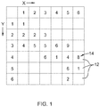
- FIG. 1 is a chart showing a data set 10 which is generally representative of a physical entity or process.
- the data contained in the data set 10 may be values measured by a measuring instrument, values sensed by one or more sensors, or engineering data representative of a physical entity, such as an engineering drawing or computer model.
- the chart includes a number of columns arrayed along an X-axis, labeled with an index (i.e. values 1 through 6 in this particular example).
- the chart further includes a number of rows arrayed along a Y-axis mutually perpendicular to the X-axis, labeled with an index (i.e. values 1 through 6 in this example).
- the chart thus includes thirty-six individual cells 12 which can be referenced by the paired X, Y index references.
- Each cell 12 contains a data value 14.
- the value may be an alphanumeric value, an integer, or a long-format number.
- the cells contain integer values.
- null or zero values are highly compressible using existing compression algorithms; this is an advantage of the data storage format described herein.
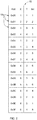
- FIG. 2 is a chart showing a prior art format for storing the information shown in the chart of FIG. 1 .
- the chart is a visual representation of a table 16 that would be stored in a digital memory operably connected to a computing device.
- computing device includes any apparatus having one or more processors operable to execute programmed instructions, such as a mainframe computer, minicomputer, microcomputer, portable computing device, or microprocessor.
- a typical computing device includes a central processing unit (“CPU”), digital memory, a power supply, and input and output devices, (e.g., display, keyboard, mouse).
- digital memory includes any structure or apparatus operable to store digital data, regardless of the underlying principle of operation, e.g. electronic, magnetic, or optical.
- digital memory devices include RAM, ROM, flash memory, magnetic or solid-state hard disk drives, optical disks, or magnetic tape.
- the table 16 contains sixteen rows 18, one row 18 being provided for each nonzero value. Each row 18 is identified by an address, here shown as a simple hexadecimal index (i.e. 0x00 through 0x0F). Each row 18 contains a stored value for the X-location, the Y-location, and the corresponding data value. It will thus be understood that in this example, it is necessary to store 48 individual values in order to completely represent the data set 10.
- FIG. 3 is a chart showing an exemplary structure for storing the information shown in the chart of FIG. 1 , following the data storage principles of an aspect of the present invention.
- the chart is a visual representation of an array 20 that would be stored in digital memory associated with a computing device.
- a first index 22 corresponds to the Y-locations as described above.
- a second index 24 corresponds to the X-locations as described above.
- the array 20 thus includes thirty-six individual cells 26 which can be mapped or addressed by the paired index references. It will be understood that other coordinate systems may be used (for example polar coordinates). It will be further understood that this data storage format is applicable to coordinate systems having any number of dimensions.
- Each cell 26 stores a data value.
- the value may be, for example, an alphanumeric value, an integer, or a long-format number.
- the physical intervals would be multiplied by the scalar multiplication or its inverse, depending on whether data is being stored or retrieved.
- this data organization concept is broadly applicable to any application in which data is stored in a point cloud. It is particularly applicable to processes in which the data relates to physical processes (e.g. measurements or sensed values).
- One exemplary application of the process is data storage related to additive manufacturing, an example of which will be described below.
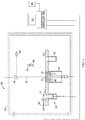
- FIG. 4 illustrates schematically an additive manufacturing apparatus 30 of a known type.
- the apparatus includes a table 32, a powder supply 34, a recoater 36, an overflow container 38, a build platform 40 surrounded by a build chamber 42, a directed energy source 44, and a beam steering apparatus 46, all surrounded by an enclosure 48.
- An example of a basic build process for a workpiece W using the apparatus 30 is as follows.
- the build platform 40 is positioned below the table 32 by a selected layer increment.
- Powder "P" is then deposited over the build platform 40, using the powder supply 34 and the recoater 36.
- the directed energy source 44 is used to melt a two-dimensional cross-section or layer of the workpiece W being built.
- the directed energy source 44 emits a beam "B” and the beam steering apparatus 46 is used to steer the focal spot "S" of the build beam B over the exposed powder surface in an appropriate pattern.
- a small portion of exposed layer of the powder P surrounding the focal spot S referred to herein as a "weld pool” is heated by the build beam B to a temperature allowing it to melt, flow, and consolidate. This step may be referred to as fusing the powder P.
- the weld pool radiates energy in a known part of the electromagnetic spectrum and the intensity of this radiated energy may be used for temperature measurement.
- the build platform 40 is moved vertically downward by the layer increment, and another layer of powder P is applied in a similar thickness.
- the directed energy source 44 again emits a build beam B and the beam steering apparatus 46 is used to steer the focal spot S of the build beam B over the exposed powder surface in an appropriate pattern.
- the exposed layer of the powder P is heated by the build beam B to a temperature allowing it to melt, flow, and consolidate both within the top layer and with the lower, previously-solidified layer. the cycle of moving the build platform 40, applying powder P, and then directed energy fusing the powder P is repeated until the entire workpiece W is complete.
- a monitoring process may be incorporated into the build process described above.
- the monitoring process includes using one or more sensors to measure signals generated during the build process.
- signals that can be measured include, for example: displacement, position, velocity, or acceleration of the various moving components of the apparatus 30, vibration or acoustic signals generated by the apparatus 30, or electromagnetic radiation generated by the apparatus 30, such as the intensity of the build beam B or of the weld pool.
- FIG. 4 illustrates non-contact sensor 50 disposed above the table 12 and configured to detect EM radiation.
- the sensor 50 may comprise a photodetector or camera having an appropriate EM band sensitivity.
- the sensor 50 is used merely as a illustrative example and it will be understood that the processing monitoring and data storage described below may be applied to other types of sensors, including but not limited to any of the other sensors described above (e.g. displacement, position, velocity, acceleration, vibration or acoustic).
- the sensor 50 may be provided with appropriate means for measuring signals with a required spatial resolution, such as using an array of sensors, or using one or more sensors that can be steered to place their field of view in a known position.
- a sensor steering apparatus 52 is used to orient the sensor 50 to an appropriate position over the exposed powder surface.
- the senor 50 is operable to detect a weld pool radiation intensity and to identify the location of the intensity measurement within the X-Y plane.
- the data produced from the sensor 50 for example, includes an intensity value for each discrete X-Y location.
- FIG. 1 may be representative of the sensed data.
- the operation of the apparatus 10, including for example control of the powder supply 34, recoater 36, build platform 40, directed energy source 44, and/or the beam steering apparatus 46, may be controlled by one or more computing devices.
- a representative computing device 54 is shown schematically in FIG. 4 , with single lines indicating operative connections to the various components (e.g. data and/or control lines). Such connections may be wired or wireless.
- the computing device 54 is operably connected to a digital memory as described above, shown schematically at 56.
- the sensor information may be used for numerous purposes. For example, it may be used for quality control by comparing a sensed weld pool intensity to a predetermined weld pool intensity (e.g. determined by process design intent or expected values determined by analysis).
- a predetermined weld pool intensity e.g. determined by process design intent or expected values determined by analysis
- predetermined weld pool information may be used for feedback control of the operation of the apparatus 10.
- weld pool intensity values from the sensor 50 may be compared to a predetermined weld pool intensity. Any difference in the sensed value in the predetermined value may be used to generate an error signal which may be fed to the apparatus 10 in use to adjust operation of the apparatus 10.
- the data from the sensors 50 would be stored in digital memory 56 using the format as described above. More specifically, the sensed value for each specific location in the X-Y plane of a particular layer would be stored in one of the cells 26 of the array 20 described above.
- the point cloud data storage format described herein has several advantages over prior art storage formats. As described in the example above, it greatly reduces the amount of storage space required. A key feature is that the reduction in storage space is "lossless", i.e., the process of reducing the amount of data storage used does not introduce errors or loss of data, as can be the case with known compression algorithms. It is not “compression” per se but rather a method of reorganizing the data to optimize what is important to capture. Furthermore, if further reductions in data storage space are desired, this data storage format is compatible with existing and future compression algorithms.
Landscapes
- Engineering & Computer Science (AREA)
- Theoretical Computer Science (AREA)
- Physics & Mathematics (AREA)
- General Physics & Mathematics (AREA)
- General Engineering & Computer Science (AREA)
- Human Computer Interaction (AREA)
- Materials Engineering (AREA)
- Chemical & Material Sciences (AREA)
- Manufacturing & Machinery (AREA)
- Software Systems (AREA)
- Geometry (AREA)
- Computer Graphics (AREA)
- Length Measuring Devices With Unspecified Measuring Means (AREA)
Abstract
Description
- The present invention relates generally to data storage, and more particularly to structures and methods for data storage of large amounts of geometric data.
- Various industrial and technical processes require electronic storage of data in a point cloud, defined as a set of points in a coordinate system. Point clouds are often used in situations in which large amounts of geometric data must be stored, e.g. data including indexed to 2-D or 3-D position information. Examples of such applications include digital video processing data, manufacturing process monitoring data, coordinate measuring machine ("CMM") data, etc.
- One particular example of the use of this kind of geometric data would be process monitoring of an additive manufacturing process. Additive manufacturing is a process in which material is built up layer-by-layer to form a component. Additive manufacturing is also referred to by terms such as "layered manufacturing," "reverse machining," "direct metal laser melting" (DMLM), "selective laser sintering" (SLS), stereolithography (SLA), and "3-D printing." Such terms are treated as synonyms for purposes of the present invention.
- One kind of process monitoring for additive manufacturing uses an optical sensor to generate weld pool intensity measurements at many individual points over the surface of workpiece.
- In the prior art, this point cloud data is generally stored in a tabular form. In this storage format, using the weld pool intensity measurement as an example, each table row stores an X position, a Y position, and the integer value of the data. One problem with this tabular format is that it requires a disproportionately large amount of storage for large data sets. While computer storage and processing power has generally become more available and less expensive, it does have finite limits and it is desirable to limit the amount of storage required.
- This problem is addressed by a method of storing point cloud data using an array structure.
- According to one aspect of the technology described herein, a method of storing a set of data representing a point cloud includes: creating an array in a digital memory having cells addressable by reference to at least one index, wherein each of the at least one indices has a predetermined correspondence to a geometric location within the point cloud; and storing a value of the data set in each of the cells.
- According to another aspect of the technology described herein, a method of storing a set of data representing a point cloud includes: using a sensor to collect data values from a physical process, each data value corresponding to a specific geometric location which is defined by reference to one or more physical coordinate indices; multiplying each of the one or more physical coordinate indices by a predetermined scalar multiplication factor, so as to produce one or more array indices; creating an array in a digital memory having cells addressable by reference to the one or more array indices; and for each specific geometric location within the point cloud, storing the sensed data value in the corresponding cell of the array.
- According to another aspect of the technology described herein, a data structure for storing a data set representing a point cloud includes: an array having a first index and a second index each correlated to a physical value; and a plurality of cells addressable by the indices, each cell containing a value of the data set.
- The invention may be best understood by reference to the following description taken in conjunction with the accompanying drawing figures in which:
-
FIG. 1 is a chart depicting an example of a dataset representing sensed information related to a physical process; -
FIG. 2 is a chart depicting a prior art format for storing the information shown inFIG. 1 ; -
FIG. 3 is a chart depicting an exemplary format for storing the information shown inFIG. 1 , according to one aspect of the present invention; and -
FIG. 4 is a schematic sectional diagram of an exemplary additive manufacturing apparatus. - Referring to the drawings wherein identical reference numerals denote the same elements throughout the various views,
FIG. 1 is a chart showing a data set 10 which is generally representative of a physical entity or process. For example, the data contained in the data set 10 may be values measured by a measuring instrument, values sensed by one or more sensors, or engineering data representative of a physical entity, such as an engineering drawing or computer model. The chart includes a number of columns arrayed along an X-axis, labeled with an index (i.e. values 1 through 6 in this particular example). The chart further includes a number of rows arrayed along a Y-axis mutually perpendicular to the X-axis, labeled with an index (i.e. values 1 through 6 in this example). The chart thus includes thirty-sixindividual cells 12 which can be referenced by the paired X, Y index references. - Each
cell 12 contains adata value 14. For example, the value may be an alphanumeric value, an integer, or a long-format number. In the illustrated example, the cells contain integer values. - For the purposes of explanation, an example is shown in which fifteen of the
cells 12 contain nonzero values (cells 12 which are shown as blank may be considered to be zero or null values). It is noted that null or zero values are highly compressible using existing compression algorithms; this is an advantage of the data storage format described herein. -
FIG. 2 is a chart showing a prior art format for storing the information shown in the chart ofFIG. 1 . The chart is a visual representation of a table 16 that would be stored in a digital memory operably connected to a computing device. - As used herein, the term "computing device" includes any apparatus having one or more processors operable to execute programmed instructions, such as a mainframe computer, minicomputer, microcomputer, portable computing device, or microprocessor. A typical computing device includes a central processing unit ("CPU"), digital memory, a power supply, and input and output devices, (e.g., display, keyboard, mouse).
- As used herein, the term "digital memory" includes any structure or apparatus operable to store digital data, regardless of the underlying principle of operation, e.g. electronic, magnetic, or optical. Nonlimiting examples of digital memory devices include RAM, ROM, flash memory, magnetic or solid-state hard disk drives, optical disks, or magnetic tape.
- The table 16 contains sixteen
rows 18, onerow 18 being provided for each nonzero value. Eachrow 18 is identified by an address, here shown as a simple hexadecimal index (i.e. 0x00 through 0x0F). Eachrow 18 contains a stored value for the X-location, the Y-location, and the corresponding data value. It will thus be understood that in this example, it is necessary to store 48 individual values in order to completely represent the data set 10. - In contrast,
FIG. 3 is a chart showing an exemplary structure for storing the information shown in the chart ofFIG. 1 , following the data storage principles of an aspect of the present invention. The chart is a visual representation of anarray 20 that would be stored in digital memory associated with a computing device. - In this format, physical positions are mapped by reference to indices that relate to memory addresses within the digital memory structure. A first index 22 (a column in this example) corresponds to the Y-locations as described above. A second index 24 (a row in this example) corresponds to the X-locations as described above.
- ). The
array 20 thus includes thirty-sixindividual cells 26 which can be mapped or addressed by the paired index references. It will be understood that other coordinate systems may be used (for example polar coordinates). It will be further understood that this data storage format is applicable to coordinate systems having any number of dimensions. - Each
cell 26 stores a data value. In one example, the value may be, for example, an alphanumeric value, an integer, or a long-format number. - In this example, it is necessary to store only 36 individual values (some of which are zero or null) in order to completely represent the data set 10.
- It will be understood that it is unlikely that the arbitrary (e.g. integer) values of the
matrix indices - In use, the physical intervals would be multiplied by the scalar multiplication or its inverse, depending on whether data is being stored or retrieved.
- As noted above, this data organization concept is broadly applicable to any application in which data is stored in a point cloud. It is particularly applicable to processes in which the data relates to physical processes (e.g. measurements or sensed values). One exemplary application of the process is data storage related to additive manufacturing, an example of which will be described below.
-
FIG. 4 illustrates schematically anadditive manufacturing apparatus 30 of a known type. The apparatus includes a table 32, apowder supply 34, arecoater 36, anoverflow container 38, abuild platform 40 surrounded by abuild chamber 42, a directedenergy source 44, and abeam steering apparatus 46, all surrounded by anenclosure 48. - An example of a basic build process for a workpiece W using the
apparatus 30 is as follows. Thebuild platform 40 is positioned below the table 32 by a selected layer increment. Powder "P" is then deposited over thebuild platform 40, using thepowder supply 34 and therecoater 36. - The directed
energy source 44 is used to melt a two-dimensional cross-section or layer of the workpiece W being built. The directedenergy source 44 emits a beam "B" and thebeam steering apparatus 46 is used to steer the focal spot "S" of the build beam B over the exposed powder surface in an appropriate pattern. A small portion of exposed layer of the powder P surrounding the focal spot S, referred to herein as a "weld pool" is heated by the build beam B to a temperature allowing it to melt, flow, and consolidate. This step may be referred to as fusing the powder P. The weld pool radiates energy in a known part of the electromagnetic spectrum and the intensity of this radiated energy may be used for temperature measurement. - The
build platform 40 is moved vertically downward by the layer increment, and another layer of powder P is applied in a similar thickness. The directedenergy source 44 again emits a build beam B and thebeam steering apparatus 46 is used to steer the focal spot S of the build beam B over the exposed powder surface in an appropriate pattern. The exposed layer of the powder P is heated by the build beam B to a temperature allowing it to melt, flow, and consolidate both within the top layer and with the lower, previously-solidified layer. the cycle of moving thebuild platform 40, applying powder P, and then directed energy fusing the powder P is repeated until the entire workpiece W is complete. - A monitoring process may be incorporated into the build process described above. Generally stated, the monitoring process includes using one or more sensors to measure signals generated during the build process. Nonlimiting examples of signals that can be measured include, for example: displacement, position, velocity, or acceleration of the various moving components of the
apparatus 30, vibration or acoustic signals generated by theapparatus 30, or electromagnetic radiation generated by theapparatus 30, such as the intensity of the build beam B or of the weld pool. - For example,
FIG. 4 illustrates non-contact sensor 50 disposed above the table 12 and configured to detect EM radiation. For example, the sensor 50 may comprise a photodetector or camera having an appropriate EM band sensitivity. The sensor 50 is used merely as a illustrative example and it will be understood that the processing monitoring and data storage described below may be applied to other types of sensors, including but not limited to any of the other sensors described above (e.g. displacement, position, velocity, acceleration, vibration or acoustic). - The sensor 50 may be provided with appropriate means for measuring signals with a required spatial resolution, such as using an array of sensors, or using one or more sensors that can be steered to place their field of view in a known position. In the illustrated example, a
sensor steering apparatus 52 is used to orient the sensor 50 to an appropriate position over the exposed powder surface. - In operation, the sensor 50 is operable to detect a weld pool radiation intensity and to identify the location of the intensity measurement within the X-Y plane. The data produced from the sensor 50, for example, includes an intensity value for each discrete X-Y location. For example,
FIG. 1 may be representative of the sensed data. - The operation of the apparatus 10, including for example control of the
powder supply 34,recoater 36,build platform 40, directedenergy source 44, and/or thebeam steering apparatus 46, may be controlled by one or more computing devices. Arepresentative computing device 54 is shown schematically inFIG. 4 , with single lines indicating operative connections to the various components (e.g. data and/or control lines). Such connections may be wired or wireless. Thecomputing device 54 is operably connected to a digital memory as described above, shown schematically at 56. - The sensor information may be used for numerous purposes. For example, it may be used for quality control by comparing a sensed weld pool intensity to a predetermined weld pool intensity (e.g. determined by process design intent or expected values determined by analysis).
- Alternatively, predetermined weld pool information may be used for feedback control of the operation of the apparatus 10. For example, weld pool intensity values from the sensor 50 may be compared to a predetermined weld pool intensity. Any difference in the sensed value in the predetermined value may be used to generate an error signal which may be fed to the apparatus 10 in use to adjust operation of the apparatus 10.
- In either case, the data from the sensors 50 would be stored in
digital memory 56 using the format as described above. More specifically, the sensed value for each specific location in the X-Y plane of a particular layer would be stored in one of thecells 26 of thearray 20 described above. - The point cloud data storage format described herein has several advantages over prior art storage formats. As described in the example above, it greatly reduces the amount of storage space required. A key feature is that the reduction in storage space is "lossless", i.e., the process of reducing the amount of data storage used does not introduce errors or loss of data, as can be the case with known compression algorithms. It is not "compression" per se but rather a method of reorganizing the data to optimize what is important to capture. Furthermore, if further reductions in data storage space are desired, this data storage format is compatible with existing and future compression algorithms.
- The foregoing has described a structure and method for storing point cloud information. All of the features disclosed in this specification (including any accompanying claims, abstract and drawings), and/or all of the steps of any method or process so disclosed, may be combined in any combination, except combinations where at least some of such features and/or steps are mutually exclusive.
- Each feature disclosed in this specification (including any accompanying claims, abstract and drawings) may be replaced by alternative features serving the same, equivalent or similar purpose, unless expressly stated otherwise. Thus, unless expressly stated otherwise, each feature disclosed is one example only of a generic series of equivalent or similar features.
- The invention is not restricted to the details of the foregoing embodiment(s). The invention extends to any novel one, or any novel combination, of the features disclosed in this specification (including any accompanying claims, abstract and drawings), or to any novel one, or any novel combination, of the steps of any method or process so disclosed.
- Various aspects and embodiments of the present invention are defined by the following clauses:
- 1. A method of storing a set of data representing a point cloud, comprising:
- creating an array in a digital memory having cells addressable by reference to at least one index, wherein each of the at least one indices has a predetermined correspondence to a geometric location within the point cloud; and
- storing a value of the data set in each of the cells.
- 2. The method of
clause 1 wherein the array includes two or more indices, corresponding to or more physical dimensions, wherein the two or more indices cooperatively define specific geometric locations within the point cloud. - 3. The method of
clause 1 wherein the array includes first and second indices, corresponding to first and second mutually perpendicular axes. - 4. The method of
clause 1 wherein the at least one index is mapped to a digital memory address. - 5. The method of
clause 1 wherein the value stored in each cell is a scalar quantity. - 6. The method of
clause 1 further comprising multiplying a physical dimension by a scalar multiplication factor to determine a value of the at least one index - 7. The method of
clause 1 where the point cloud is representative of a physical manufacturing process. - 8. The method of
clause 1 where the point cloud is representative of an additive manufacturing process. - 9. A method of storing a set of data representing a point cloud, comprising:
- using a sensor to collect data values from a physical process, each data value corresponding to a specific geometric location which is defined by reference to one or more physical coordinate indices;
- multiplying each of the one or more physical coordinate indices by a predetermined scalar multiplication factor, so as to produce one or more array indices;
- creating an array in a digital memory having cells addressable by reference to the one or more array indices; and
- for each specific geometric location within the point cloud, storing the sensed data value in the corresponding cell of the array.
- 10. The method of clause 9 wherein the array includes two or more indices, corresponding to or more physical dimensions, wherein the two or more indices cooperatively define specific geometric locations within the point cloud.
- 11. The method of clause 9 wherein the array includes first and second indices, corresponding to first and second mutually perpendicular axes.
- 12. The method of clause 9 wherein the at one or more array indices are mapped to digital memory addresses.
- 13. The method of clause 9 wherein the value stored in each cell is a scalar quantity.
- 14. The method of clause 9 where the sensed data is collected from a physical manufacturing process.
- 15. The method of clause 9 where the sensed data is collected from an additive manufacturing process.
- 16. A data structure for storing a data set representing a point cloud, comprising:
- an array having a first index and a second index each correlated to a physical value; and
- a plurality of cells addressable by the indices, each cell containing a value of the data set.
- 17. The data structure of
clause 16 stored in a digital memory. - 18. The data structure of
clause 16 further comprising a multiplier correlating the indices to physical measurements.
Claims (15)
- A method of storing a set of data representing a point cloud, comprising:creating an array (20) in a digital memory (56) having cells (26) addressable by reference to at least one index (22, 24), wherein each of the at least one indices (22, 24) has a predetermined correspondence to a geometric location within the point cloud; andstoring a value of the data set in each of the cells (26).
- The method of claim 1 wherein the array (20) includes two or more indices (22, 24), corresponding to or more physical dimensions, wherein the two or more indices (22, 24) cooperatively define specific geometric locations within the point cloud.
- The method of claim 1 or 2 wherein the array (20) includes first and second indices (22, 24), corresponding to first and second mutually perpendicular axes.
- The method of any one of claims 1 to 3 wherein the at least one index (22, 24) is mapped to a digital memory address.
- The method of any one of claims 1 to 4 wherein the value stored in each cell (26) is a scalar quantity.
- The method of any one of claims 1 to 5 further comprising multiplying a physical dimension by a scalar multiplication factor to determine a value of the at least one index (22, 24)
- The method of any one of claims 1 to 6 where the point cloud is representative of a physical manufacturing process.
- The method of any one of claims 1 to 7 where the point cloud is representative of an additive manufacturing process.
- A method of storing a set of data representing a point cloud, comprising:using a sensor (50) to collect data values from a physical process, each data value corresponding to a specific geometric location which is defined by reference to one or more physical coordinate indices;multiplying each of the one or more physical coordinate indices by a predetermined scalar multiplication factor, so as to produce one or more array indices (22, 24);creating an array (20) in a digital memory (56) having cells (26) addressable by reference to the one or more array indices (22, 24); andfor each specific geometric location within the point cloud, storing the sensed data value in the corresponding cell (26) of the array (20).
- The method of claim 9 wherein the array (20) includes two or more indices (22, 24), corresponding to or more physical dimensions, wherein the two or more indices (22, 24) cooperatively define specific geometric locations within the point cloud.
- The method of claim 9 or 10 wherein the array (20) includes first and second indices (22, 24), corresponding to first and second mutually perpendicular axes.
- The method of any one of claims 9 to 11 wherein the at one or more array indices (22, 24) are mapped to digital memory addresses.
- A data structure for storing a data set representing a point cloud, comprising:an array (20) having a first index (22, 24) and a second index (22, 24) each correlated to a physical value; anda plurality of cells (26) addressable by the indices (22, 24), each cell (26) containing a value of the data set.
- The data structure of claim 13 stored in a digital memory (56).
- The data structure of claim 13 or 14 further comprising a multiplier correlating the indices (22, 24) to physical measurements.
Applications Claiming Priority (1)
| Application Number | Priority Date | Filing Date | Title |
|---|---|---|---|
| US15/659,136 US11422725B2 (en) | 2017-07-25 | 2017-07-25 | Point-cloud dataset storage structure and method thereof |
Publications (1)
| Publication Number | Publication Date |
|---|---|
| EP3435337A1 true EP3435337A1 (en) | 2019-01-30 |
Family
ID=63047093
Family Applications (1)
| Application Number | Title | Priority Date | Filing Date |
|---|---|---|---|
| EP18182079.6A Withdrawn EP3435337A1 (en) | 2017-07-25 | 2018-07-06 | Data storage structure and method |
Country Status (4)
| Country | Link |
|---|---|
| US (1) | US11422725B2 (en) |
| EP (1) | EP3435337A1 (en) |
| JP (1) | JP2019081350A (en) |
| CN (1) | CN109298834A (en) |
Cited By (1)
| Publication number | Priority date | Publication date | Assignee | Title |
|---|---|---|---|---|
| CN114147239A (en) * | 2021-12-07 | 2022-03-08 | 浙江机电职业技术学院 | SLM forming process parameter monitoring system |
Families Citing this family (2)
| Publication number | Priority date | Publication date | Assignee | Title |
|---|---|---|---|---|
| CN111680095B (en) * | 2020-06-10 | 2021-01-12 | 上海城市地理信息系统发展有限公司 | Method and device for processing point cloud data and electronic equipment |
| CN117291789B (en) * | 2023-11-27 | 2024-02-27 | 北京超星未来科技有限公司 | Point cloud data storage method, device, equipment and readable storage medium |
Citations (1)
| Publication number | Priority date | Publication date | Assignee | Title |
|---|---|---|---|---|
| US7317456B1 (en) * | 2002-12-02 | 2008-01-08 | Ngrain (Canada) Corporation | Method and apparatus for transforming point cloud data to volumetric data |
Family Cites Families (25)
| Publication number | Priority date | Publication date | Assignee | Title |
|---|---|---|---|---|
| US6377865B1 (en) * | 1998-02-11 | 2002-04-23 | Raindrop Geomagic, Inc. | Methods of generating three-dimensional digital models of objects by wrapping point cloud data points |
| WO2002009419A2 (en) | 2000-07-20 | 2002-01-31 | Giant Leap Ahead Limited | Method and apparatus for determining motion vectors in dynamic images |
| WO2003088085A1 (en) * | 2002-04-04 | 2003-10-23 | Arizona Board Of Regents | Three-dimensional digital library system |
| US7895025B2 (en) | 2004-03-10 | 2011-02-22 | Renault S.A.S. | Validation method for embedded systems |
| US7990397B2 (en) | 2006-10-13 | 2011-08-02 | Leica Geosystems Ag | Image-mapped point cloud with ability to accurately represent point coordinates |
| CN101871767B (en) * | 2009-04-25 | 2012-05-30 | 鸿富锦精密工业(深圳)有限公司 | System and method for detecting form and position tolerance of components |
| US9317965B2 (en) * | 2009-11-16 | 2016-04-19 | Autodesk, Inc. | Uniform point cloud decimation |
| CN102729476B (en) | 2011-04-11 | 2014-10-15 | 研能科技股份有限公司 | Control method of three-dimensional forming mechanism |
| CN103020080A (en) * | 2011-09-23 | 2013-04-03 | 鸿富锦精密工业(深圳)有限公司 | Method and system for rapidly reading point cloud document |
| US9182913B2 (en) * | 2011-10-18 | 2015-11-10 | Ubiterra Corporation | Apparatus, system and method for the efficient storage and retrieval of 3-dimensionally organized data in cloud-based computing architectures |
| DE102011121956A1 (en) | 2011-12-23 | 2013-06-27 | Arburg Gmbh + Co. Kg | Control method for characteristic map determination |
| US9390110B2 (en) * | 2012-05-02 | 2016-07-12 | Level Set Systems Inc. | Method and apparatus for compressing three-dimensional point cloud data |
| US20140067333A1 (en) * | 2012-09-04 | 2014-03-06 | Belcan Corporation | CAD-Based System for Product Definition, Inspection and Validation |
| US8872818B2 (en) * | 2013-03-15 | 2014-10-28 | State Farm Mutual Automobile Insurance Company | Methods and systems for capturing the condition of a physical structure |
| US9508186B2 (en) * | 2013-11-07 | 2016-11-29 | Autodesk, Inc. | Pre-segment point cloud data to run real-time shape extraction faster |
| US9691006B2 (en) * | 2013-12-20 | 2017-06-27 | Visual Technology Services Limited | Point cloud simplification |
| US9925724B2 (en) | 2014-07-03 | 2018-03-27 | United Technologies Corporation | Additive manufacturing system and method of additive manufacture utilizing layer-by-layer thermo-mechanical analysis |
| CN104200518A (en) | 2014-08-06 | 2014-12-10 | 北京工业大学 | Triangular grid re-gridding method based on geometrical image |
| US9789650B2 (en) | 2014-10-15 | 2017-10-17 | Adobe Systems Inc. | Conversion of stereolithographic model into logical subcomponents |
| CN107206495B (en) | 2015-01-29 | 2019-07-02 | 奥科宁克有限公司 | Method for creating a 3D volumetric mass model |
| US10201938B2 (en) | 2015-03-02 | 2019-02-12 | Xerox Corporation | Extracting an embedded database from a physical object |
| EP3098677B1 (en) | 2015-05-27 | 2019-05-08 | Ansaldo Energia IP UK Limited | Method for machining a component on a multi-axis machine tool driven by an nc-controller and apparatus for conducting said method |
| US10672045B2 (en) | 2015-09-11 | 2020-06-02 | Caterpillar Inc. | Systems and methods for processing orders for structural designs |
| US20170090460A1 (en) | 2015-09-25 | 2017-03-30 | Microsoft Technology Licensing, Llc | 3D Model Generation From Map Data |
| CN105844602B (en) | 2016-04-01 | 2018-11-20 | 辽宁工程技术大学 | A kind of airborne LIDAR point cloud three-dimensional filtering method based on volume elements |
-
2017
- 2017-07-25 US US15/659,136 patent/US11422725B2/en active Active
-
2018
- 2018-07-06 EP EP18182079.6A patent/EP3435337A1/en not_active Withdrawn
- 2018-07-20 JP JP2018136289A patent/JP2019081350A/en active Pending
- 2018-07-24 CN CN201810819935.0A patent/CN109298834A/en active Pending
Patent Citations (1)
| Publication number | Priority date | Publication date | Assignee | Title |
|---|---|---|---|---|
| US7317456B1 (en) * | 2002-12-02 | 2008-01-08 | Ngrain (Canada) Corporation | Method and apparatus for transforming point cloud data to volumetric data |
Cited By (1)
| Publication number | Priority date | Publication date | Assignee | Title |
|---|---|---|---|---|
| CN114147239A (en) * | 2021-12-07 | 2022-03-08 | 浙江机电职业技术学院 | SLM forming process parameter monitoring system |
Also Published As
| Publication number | Publication date |
|---|---|
| US11422725B2 (en) | 2022-08-23 |
| JP2019081350A (en) | 2019-05-30 |
| US20190034109A1 (en) | 2019-01-31 |
| CN109298834A (en) | 2019-02-01 |
Similar Documents
| Publication | Publication Date | Title |
|---|---|---|
| Khanzadeh et al. | Quantifying geometric accuracy with unsupervised machine learning: Using self-organizing map on fused filament fabrication additive manufacturing parts | |
| Huang | An analytical foundation for optimal compensation of three-dimensional shape deformation in additive manufacturing | |
| Pan et al. | Multitool and multi-axis computer numerically controlled accumulation for fabricating conformal features on curved surfaces | |
| US20200307174A1 (en) | Systems and methods for structurally analyzing and printing parts | |
| EP3435337A1 (en) | Data storage structure and method | |
| Mears et al. | Quality and inspection of machining operations: CMM integration to the machine tool | |
| EP3283840A1 (en) | Cmm probe path controller and method | |
| CN107063060A (en) | A kind of method and device for determining surface planarity | |
| Panhalkar et al. | Increasing part accuracy in additive manufacturing processes using a kd tree based clustered adaptive layering | |
| Chengyang et al. | Thermal error modeling of rotary axis based on convolutional neural network | |
| CN113198692B (en) | High-precision dispensing method and device suitable for batch products | |
| Luan et al. | Prescriptive data-analytical modeling of laser powder bed fusion processes for accuracy improvement | |
| Hussain et al. | Straight-build assembly optimization: A method to minimize stage-by-stage eccentricity error in the assembly of axisymmetric rigid components (two-dimensional case study) | |
| Shao et al. | Dynamic sampling design for characterizing spatiotemporal processes in manufacturing | |
| Kadashevich et al. | A novel simulation approach to determine thermally induced geometric deviations in dry gear hobbing | |
| Xiong et al. | Probe radius compensation of workpiece localization | |
| Smith et al. | Point laser triangulation probe calibration for coordinate metrology | |
| Wang et al. | Research on the printing error of tilted vertical beams in delta-robot 3D printers | |
| Qi et al. | Line-feature-based calibration method of structured light plane parameters for robot hand-eye system | |
| Wu et al. | A unified calibration method of 3D laser profile measurement with different of laser-line lengths | |
| Cousin et al. | Digitalization of a robot-based directed energy deposition process for In-situ monitoring and post-process data analytics | |
| Zhang et al. | 3D double-vision inspection based on structured light | |
| Zhang et al. | Scalable thermal simulation of powder bed fusion | |
| CN205403709U (en) | Work piece size detection device | |
| CN108489400A (en) | A kind of electron beam fuse increasing material manufacturing shaping surface state monitoring apparatus and method |
Legal Events
| Date | Code | Title | Description |
|---|---|---|---|
| PUAI | Public reference made under article 153(3) epc to a published international application that has entered the european phase |
Free format text: ORIGINAL CODE: 0009012 |
|
| STAA | Information on the status of an ep patent application or granted ep patent |
Free format text: STATUS: THE APPLICATION HAS BEEN PUBLISHED |
|
| AK | Designated contracting states |
Kind code of ref document: A1 Designated state(s): AL AT BE BG CH CY CZ DE DK EE ES FI FR GB GR HR HU IE IS IT LI LT LU LV MC MK MT NL NO PL PT RO RS SE SI SK SM TR |
|
| AX | Request for extension of the european patent |
Extension state: BA ME |
|
| STAA | Information on the status of an ep patent application or granted ep patent |
Free format text: STATUS: REQUEST FOR EXAMINATION WAS MADE |
|
| 17P | Request for examination filed |
Effective date: 20190717 |
|
| RBV | Designated contracting states (corrected) |
Designated state(s): AL AT BE BG CH CY CZ DE DK EE ES FI FR GB GR HR HU IE IS IT LI LT LU LV MC MK MT NL NO PL PT RO RS SE SI SK SM TR |
|
| STAA | Information on the status of an ep patent application or granted ep patent |
Free format text: STATUS: EXAMINATION IS IN PROGRESS |
|
| 17Q | First examination report despatched |
Effective date: 20210610 |
|
| STAA | Information on the status of an ep patent application or granted ep patent |
Free format text: STATUS: THE APPLICATION IS DEEMED TO BE WITHDRAWN |
|
| 18D | Application deemed to be withdrawn |
Effective date: 20211021 |