EP3435294B1 - Systeme und verfahren zur lösung inverser probleme mit einem gekoppelten autoencoder - Google Patents
Systeme und verfahren zur lösung inverser probleme mit einem gekoppelten autoencoder Download PDFInfo
- Publication number
- EP3435294B1 EP3435294B1 EP18156212.5A EP18156212A EP3435294B1 EP 3435294 B1 EP3435294 B1 EP 3435294B1 EP 18156212 A EP18156212 A EP 18156212A EP 3435294 B1 EP3435294 B1 EP 3435294B1
- Authority
- EP
- European Patent Office
- Prior art keywords
- autoencoder
- variable
- target
- represented
- source
- Prior art date
- Legal status (The legal status is an assumption and is not a legal conclusion. Google has not performed a legal analysis and makes no representation as to the accuracy of the status listed.)
- Active
Links
Images


Classifications
-
- G—PHYSICS
- G06—COMPUTING OR CALCULATING; COUNTING
- G06T—IMAGE DATA PROCESSING OR GENERATION, IN GENERAL
- G06T5/00—Image enhancement or restoration
- G06T5/73—Deblurring; Sharpening
-
- G—PHYSICS
- G06—COMPUTING OR CALCULATING; COUNTING
- G06N—COMPUTING ARRANGEMENTS BASED ON SPECIFIC COMPUTATIONAL MODELS
- G06N3/00—Computing arrangements based on biological models
- G06N3/02—Neural networks
- G06N3/04—Architecture, e.g. interconnection topology
- G06N3/045—Combinations of networks
- G06N3/0455—Auto-encoder networks; Encoder-decoder networks
-
- G—PHYSICS
- G06—COMPUTING OR CALCULATING; COUNTING
- G06N—COMPUTING ARRANGEMENTS BASED ON SPECIFIC COMPUTATIONAL MODELS
- G06N3/00—Computing arrangements based on biological models
- G06N3/02—Neural networks
- G06N3/04—Architecture, e.g. interconnection topology
- G06N3/0499—Feedforward networks
-
- G—PHYSICS
- G06—COMPUTING OR CALCULATING; COUNTING
- G06N—COMPUTING ARRANGEMENTS BASED ON SPECIFIC COMPUTATIONAL MODELS
- G06N3/00—Computing arrangements based on biological models
- G06N3/02—Neural networks
- G06N3/08—Learning methods
- G06N3/09—Supervised learning
-
- G—PHYSICS
- G06—COMPUTING OR CALCULATING; COUNTING
- G06N—COMPUTING ARRANGEMENTS BASED ON SPECIFIC COMPUTATIONAL MODELS
- G06N3/00—Computing arrangements based on biological models
- G06N3/02—Neural networks
- G06N3/08—Learning methods
- G06N3/094—Adversarial learning
-
- G—PHYSICS
- G06—COMPUTING OR CALCULATING; COUNTING
- G06N—COMPUTING ARRANGEMENTS BASED ON SPECIFIC COMPUTATIONAL MODELS
- G06N3/00—Computing arrangements based on biological models
- G06N3/02—Neural networks
- G06N3/08—Learning methods
- G06N3/096—Transfer learning
-
- G—PHYSICS
- G06—COMPUTING OR CALCULATING; COUNTING
- G06T—IMAGE DATA PROCESSING OR GENERATION, IN GENERAL
- G06T1/00—General purpose image data processing
- G06T1/20—Processor architectures; Processor configuration, e.g. pipelining
-
- G—PHYSICS
- G06—COMPUTING OR CALCULATING; COUNTING
- G06T—IMAGE DATA PROCESSING OR GENERATION, IN GENERAL
- G06T5/00—Image enhancement or restoration
- G06T5/60—Image enhancement or restoration using machine learning, e.g. neural networks
-
- G—PHYSICS
- G06—COMPUTING OR CALCULATING; COUNTING
- G06T—IMAGE DATA PROCESSING OR GENERATION, IN GENERAL
- G06T5/00—Image enhancement or restoration
- G06T5/70—Denoising; Smoothing
-
- G—PHYSICS
- G06—COMPUTING OR CALCULATING; COUNTING
- G06T—IMAGE DATA PROCESSING OR GENERATION, IN GENERAL
- G06T9/00—Image coding
-
- G—PHYSICS
- G06—COMPUTING OR CALCULATING; COUNTING
- G06T—IMAGE DATA PROCESSING OR GENERATION, IN GENERAL
- G06T2207/00—Indexing scheme for image analysis or image enhancement
- G06T2207/20—Special algorithmic details
- G06T2207/20081—Training; Learning
-
- G—PHYSICS
- G06—COMPUTING OR CALCULATING; COUNTING
- G06T—IMAGE DATA PROCESSING OR GENERATION, IN GENERAL
- G06T2207/00—Indexing scheme for image analysis or image enhancement
- G06T2207/20—Special algorithmic details
- G06T2207/20084—Artificial neural networks [ANN]
-
- G—PHYSICS
- G06—COMPUTING OR CALCULATING; COUNTING
- G06T—IMAGE DATA PROCESSING OR GENERATION, IN GENERAL
- G06T2210/00—Indexing scheme for image generation or computer graphics
- G06T2210/52—Parallel processing
Definitions
- the disclosure herein generally relate to a coupled autoencoder, and, more particularly, to systems and methods for solving inverse problems using a coupled autoencoder.
- An inverse problem in science is the process of calculating from a set of observations the causal factors that produced them: for example, calculating an image in computer tomography, etc.
- Inverse problems are some of the most important mathematical problems in science and mathematics because they tell about parameters that cannot be directly observed. They have wide application in signal processing, machine learning, image processing, etc.
- Motion blurring is one of the common source of image corruption in image processing techniques. It can be caused due to multiple reasons such as lens aberrations, camera shaking, long exposure time etc.
- deblurring The process of recovering sharp images from blurred images.
- Conventional deblurring techniques implement non-generalized kernel based approaches. However these approaches may not be efficient and are computational complex.
- CNNs Convolutional neural networks
- the present disclosure describes systems and methods for solving inverse problems using a coupled autoencoder. It describes a joint optimization technique for coupled autoencoder which learns the autoencoder weights and coupling map (between source and target) simultaneously. The technique is applicable to any transfer learning problem. It describes a formulation that recasts deblurring as a transfer learning problem which is solved using the proposed coupled autoencoder. It may be implemented in one or more fields, for example, optics, radar, acoustics, signal processing, medical imaging, computer vision, machine learning, and so on wherein input is unknown corrupted sample(s) to generate one or more clean samples thereof as output(s).
- FIGS. 1 through 4 where similar reference characters denote corresponding features consistently throughout the figures.
- FIG. 1 illustrates an exemplary block diagram of a system 100 for solving inverse problems using a coupled autoencoder 108.
- the system 100 includes one or more processors 104, communication interface device(s) or input/output (I/O) interface(s) 106, and one or more data storage devices or memory 102 operatively coupled to the one or more processors 104.
- the one or more processors 104 may be one or more software processing modules and/or hardware processors.
- the hardware processors can be implemented as one or more microprocessors, microcomputers, microcontrollers, digital signal processors, central processing units, state machines, logic circuitries, and/or any devices that manipulate signals based on operational instructions.
- the processor(s) is configured to fetch and execute computer-readable instructions stored in the memory.
- the device 100 can be implemented in a variety of computing systems, such as laptop computers, notebooks, hand-held devices, workstations, mainframe computers, servers, a network cloud and the like.
- the I/O interface device(s) 106 can include a variety of software and hardware interfaces, for example, a web interface, a graphical user interface, and the like and can facilitate multiple communications within a wide variety of networks N/W and protocol types, including wired networks, for example, LAN, cable, etc., and wireless networks, such as WLAN, cellular, or satellite.
- the I/O interface device(s) can include one or more ports for connecting a number of devices to one another or to another server.
- the memory 102 may include any computer-readable medium known in the art including, for example, volatile memory, such as static random access memory (SRAM) and dynamic random access memory (DRAM), and/or non-volatile memory, such as read only memory (ROM), erasable programmable ROM, flash memories, hard disks, optical disks, and magnetic tapes.
- volatile memory such as static random access memory (SRAM) and dynamic random access memory (DRAM)
- non-volatile memory such as read only memory (ROM), erasable programmable ROM, flash memories, hard disks, optical disks, and magnetic tapes.
- ROM read only memory
- ROM erasable programmable ROM
- flash memories hard disks
- optical disks optical disks
- magnetic tapes magnetic tapes.
- the coupled autoencoder 108 and a database 110 of the system 100 can be stored in the memory 102, wherein the database 110 may comprise, but are not limited to unknown corrupted samples, clean samples, training dataset, naturally-blurred and
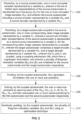
- FIG. 2 illustrates an exemplary flow diagram of a method for solving inverse problems using the coupled autoencoder 108 of the system 100 of FIG. 1 .
- the system(s) 100 comprises one or more data storage devices or the memory 102 operatively coupled to the one or more hardware processors 104 and is configured to store instructions for execution of steps of the method by the one or more processors 104.
- the steps of the method of the present disclosure will now be explained with reference to the components of the system 100 as depicted in FIG. 1 , and the flow diagram.
- Solving inverse problems may comprise, but are not limited to, generating clean images from blurred images, de-noising of noisy or distorted samples (or images), and so on.
- the one or more hardware processors 104 receives (202), via a source autoencoder, one or more corrupted samples (represented by a variable X S ), wherein a first set of hidden layer representations of the source autoencoder is represented as a first proxy (Z S ) for the one or more corrupted image samples (X S ).
- the source autoencoder is configured to receive one or more corrupted samples from the database 110 (or manually fed by one or more users).
- the source autoencoder comprises a source encoder represented by a variable W ES and a source decoder represented by a variable
- a target autoencoder coupled to the source autoencoder wherein the target autoencoder is configured to receive, one or more corresponding clean image samples (represented by a variable X T ).
- a second set of hidden layer representations of the target autoencoder is represented as a second proxy represented by a variable Z T for the corresponding clean image samples represented by a variable X T .
- the target autoencoder comprises a target encoder represented by a variable W ET and a target decoder represented by a variable W DT .
- the target autoencoder is configured to receive one or more corresponding clean samples from the database 110 (or manually fed by one or more users).
- the first proxy Z S and the second proxy Z T are coupled, using a coupling mechanism (M), which form a Lagrangian formulation, and wherein a plurality of Bregman relaxation variables (B S ) and (B T ) are initialized for the source autoencoder and the target autoencoder respectively.
- M coupling mechanism
- the coupling mechanism M learns to map the representation from the source (corrupted) to the target (clean), which is expressed by way of example as illustrated below: argmin W DS , W ES , W DT , W ET , M ⁇ X S ⁇ W DS ⁇ W ES X S ⁇ 2 F + ⁇ X T ⁇ W DT ⁇ W ET X T ⁇ 2 F + ⁇ ⁇ ⁇ W ET X T ⁇ M ⁇ W ES X S ⁇ 2 F
- ⁇ X S - W DS ⁇ ( W ES X S ) ⁇ 2 F is autoencoder formulation for source
- ⁇ X T - W DT ⁇ ( W ET X T ) ⁇ 2 F is autoencoder formulation for target
- ⁇ ⁇ ⁇ ( W ET X T ) - M ⁇ ( W ES X S ) ⁇ 2 F is coupling term.
- the linear map M (or coupling mechanism) couples the representations (e.g., the one or more hidden layer representations) from the source to that of the target.
- the above expression is solved using a variable splitting technique.
- one or more Bregman relaxation variables are introduced B S and B T such that the value of the hyper-parameter need not be changed; the relaxation variable is updated in every iteration automatically so that it enforces equality at convergence.
- the split Bregman formulation is expressed as below by way of example: argmin W DS , W ES , W DT , W ET , M , Z s , Z T ⁇ X S ⁇ W DS Z S ⁇ 2 F + ⁇ X T ⁇ W DT Z T ⁇ 2 F + ⁇ ⁇ Z T ⁇ MZ S ⁇ 2 F + n ⁇ Z S ⁇ ⁇ W ES X S ⁇ B S ⁇ 2 F
- the coupled autoencoder 108 divides the above Lagrangian formulation as expressed in equation (2) into one or more sub-problems as expressed by way of examples below:
- P 1 argmin W DS ⁇ X S ⁇ W DS Z S ⁇ F 2
- P 2 argmin W DT ⁇ X T ⁇ W DT Z T ⁇ F 2
- P 3 argmin W ES ⁇ Z S ⁇ ⁇ W ES X S ⁇ B S ⁇ F 2 ⁇ argmin W ES ⁇ ⁇ ⁇ 1 Z S ⁇ B S ⁇ W ES X S ⁇ F 2
- P 4 argmin W ET ⁇ Z T ⁇ ⁇ W ET X T ⁇ B T ⁇ F 2 ⁇ argmin W ET ⁇ ⁇ ⁇ 1 Z T ⁇ B T ⁇ W ET X T ⁇ F 2
- P 5 argmin Z S ⁇ X S ⁇ W DS Z S ⁇ F 2 + ⁇ ⁇ Z T
- the above one or more sub-problems (P1 till P7) are solved by learning each of the source decoder (W DS ), the target decoder (W DT ), the first proxy (Z S ), the second proxy (Z T ), the coupling mechanism (M), the plurality of Bregman relaxation variables B S and B T , the source encoder (W ES ), the target encoder (W ET ) pertaining to the source autoencoder and the target autoencoder respectively.
- the step of learning each of the source decoder (W DS ), the target decoder (W DT ), the first proxy (Z S ), the second proxy (Z T ), the coupling mechanism (M), the plurality of Bregman relaxation variables B S and B T , the source encoder (W ES ), the target encoder (W ET ) pertaining to the source autoencoder and the target autoencoder respectively comprises learning one or more values associated with each of the source decoder (W DS ), the target decoder (W DT ), the first proxy (Z S ), the second proxy (Z T ), the coupling mechanism (M), the plurality of Bregman relaxation variables B S and B T , the source encoder (W ES ), the target encoder (W ET ) pertaining to the source autoencoder and the target autoencoder respectively.
- sub-problems P1, P2, P5, P6, P7 are simple least squares problems having an analytic solution in the form of pseudoinverse.
- Sub-problems P3 and P4 are originally non-linear least squares problems; but since the activation function is trivial to invert (it is applied element-wise), P3 and P4 are converted to simple linear least squares problems and solved using pseudoinverse.
- the coupled autoencoder 108 iteratively updates the plurality of Bregman relaxation variables (B S ) and (B T ) using an optimization technique.
- the optimization technique may be a gradient descent optimization technique.
- the plurality of Bregman relaxation variables (B S ) and (B T ) may be iteratively updated by using the following expressions illustrated by way of examples: B s ⁇ ⁇ W ES X S + B S ⁇ Z S B T ⁇ ⁇ W ET X T + B T ⁇ Z T
- Iterations criteria is defined to be terminated when it reaches a specified maximum number of iterations or when the objective function converges to a local minimum. By convergence it is meant that the value of the objective function does not change much in successive iterations.
- the coupled autoencoder 108 is configured to receive an unknown corrupted sample
- the source decoder (W DS ) is configured to: receive the unknown corrupted sample from the coupled autoencoder 108, and one or more hidden layer representations of the unknown corrupted sample are obtained and transmitted to the coupling mechanism (M) which further transmits to the target encoder (W ET ).
- the coupled autoencoder 108 is further configured to: couple (e.g., using the coupling mechanism M), the obtained hidden layer representations with each other to obtain one or more hidden layer representations pertaining to the target autoencoder, and transmits the hidden layer representations pertaining to the target autoencoder to the target encoder for generation of a clean sample from the unknown corrupted sample.
- the target encoder then generates a clean sample (e.g., a clean image) from the unknown corrupted sample (e.g., a corrupted image or a blur image or a noisy image or a distorted image).
- Images from image blur dataset were used which contained 630 undistorted, 220 naturally-blurred and 150 artificially-blurred images in the training set and 619 undistorted, 411 naturally blurred and 450 artificially blurred images in the evaluation set. For performance evaluation a small subset of the dataset was considered. Around 50 images were taken for training, 20 images for testing and were corrupted with the motion blur kernels. The methodology was tested for two scenarios uniform kernel and non-uniform kernel. For training and testing, whole image was divided into number of overlapping patches. Each individual patch acts as a sample. The blurry patches are used to train the source autoencoder, the corresponding clean patches to train the target autoencoder and a mapping is learnt between the target and source representation.
- the blurred patch was given as the input of the source.
- the corresponding source representation was obtained from the source encoder from which the target representation is obtained by the coupling map.
- the decoder of the target was used to generate the clean (deblurred) patch.
- the whole image was reconstructed by placing patches at their locations and averaging at the overlapping regions. This eliminates the need of blocking artefacts and post processing of the recovered images. Patches of 40x40 with an overlapping of 20x20 were used for all the images.
- the input size for the autoencoders hence become 1600 and were learnt with 1400 hidden nodes.
- FIG. 3 illustrates an exemplary schematic diagram of the coupled autoencoder 108 of the system 100 according to an embodiment of the present disclosure.
- the proposed method of the present disclosure is also compared with existing techniques (ET) which estimates the kernel and retrieve deblurred image by deconvolution and which learns a Vectorized CNN for deblurring.
- E existing techniques
- the consolidated results are shown in below Table 1.
- the PSNR Peak signal-to-noise ratio
- SSIM structural similarity
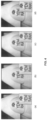
- FIG. 4 depict Non-uniform Blur Removal Comparison of the proposed methodology and existing techniques. More particularly, image (a) of FIG. 4 depicts Ground truth, image (b) of FIG. 4 depicts output generated by ET 3 (from Table 1), image (c) of FIG. 4 depicts output generated by ET 4 (from Table 1), and image (d) of FIG. 4 depicts output generated by the coupled autoencoder 108 of the system 100 of the present disclosure.
- PSNR, SSIM of ET 3 are 21.43 0.73 respectively
- PSNR, SSIM of ET 4 are 21.91 and 0.76 respectively
- PSNR, SSIM of the coupled autoencoder 108 of the system 100 of the present disclosure are 30.37 and 0.89 respectively.
- the hardware device can be any kind of device which can be programmed including e.g. any kind of computer like a server or a personal computer, or the like, or any combination thereof.
- the device may also include means which could be e.g. hardware means like e.g. an application-specific integrated circuit (ASIC), a field-programmable gate array (FPGA), or a combination of hardware and software means, e.g. an ASIC and an FPGA, or at least one microprocessor and at least one memory with software modules located therein.
- the means can include both hardware means and software means.
- the method described herein could be implemented in hardware and software.
- the device may also include software means. It may be implemented on different hardware devices, e.g. using a plurality of CPUs.
- Devices herein can comprise hardware and software elements.
- Software implementations include but are not limited to, firmware, resident software, microcode, etc.
- the functions performed by various modules described herein may be implemented in other modules or combinations of other modules.
- a computerusable or computer readable medium can be any apparatus that can comprise, store, communicate, propagate, or transport the program for use by or in connection with the instruction execution system, apparatus, or device.
- a computer-readable storage medium refers to any type of physical memory on which information or data readable by a processor may be stored. Thus, a computer-readable storage medium may store instructions for execution by one or more processors.
- the term "computer-readable medium” should be understood to include tangible items and exclude carrier waves and transient signals, i.e., be non-transitory. Examples include random access memory (RAM), read-only memory (ROM), volatile memory, nonvolatile memory, hard drives, CD ROMs, DVDs, flash drives, disks, and any other known physical storage media.
Landscapes
- Engineering & Computer Science (AREA)
- Physics & Mathematics (AREA)
- Theoretical Computer Science (AREA)
- General Physics & Mathematics (AREA)
- Computational Linguistics (AREA)
- Data Mining & Analysis (AREA)
- Life Sciences & Earth Sciences (AREA)
- Artificial Intelligence (AREA)
- Biomedical Technology (AREA)
- Biophysics (AREA)
- Software Systems (AREA)
- Health & Medical Sciences (AREA)
- Evolutionary Computation (AREA)
- General Health & Medical Sciences (AREA)
- Molecular Biology (AREA)
- Computing Systems (AREA)
- General Engineering & Computer Science (AREA)
- Mathematical Physics (AREA)
- Multimedia (AREA)
- Compression Or Coding Systems Of Tv Signals (AREA)
Claims (9)
- System (100), umfassend:einen Speicher (102), der Anweisungen speichert;eine oder mehrere Kommunikationsschnittstellen (106); undeinen oder mehrere Hardwareprozessoren (104), die über die eine oder die mehreren Kommunikationsschnittstellen (106) mit dem Speicher (102) gekoppelt sind, wobei der eine oder die mehreren Hardwareprozessoren (104) durch die Anweisungen konfiguriert sind, um Folgendes auszuführen:wobei der gekoppelte Autoencoder ferner konfiguriert ist zum:einen gekoppelten Autoencoder, der im Speicher gespeichert ist, wobei der gekoppelte Autoencoder umfasst:einen Quell-Autoencoder, der einen Quellcodierer, der durch eine Variable WES dargestellt wird, und einen Quelldecodierer, der durch eine Variable WDS dargestellt wird, beinhaltet, wobei der Quell-Autoencoder konfiguriert ist, um eine oder mehrere beschädigte Bildproben zu empfangen, die durch eine Variable Xs dargestellt werden, wobei die beschädigten Bildproben Patches eines beschädigten Bilds sind und wobei ein erster Satz von Darstellungen verborgener Schichten des Quell-Autoencoders durch einen ersten Proxy dargestellt wird, der durch eine Variable ZS für die eine oder die mehreren beschädigten Bildproben dargestellt wird, die durch die Variable XS dargestellt werden;einen Ziel-Autoencoder, der mit dem Quell-Autoencoder über einen Kopplungsmechanismus gekoppelt ist, der durch eine lineare Abbildung M dargestellt wird, wobei der Ziel-Autoencoder einen Zielcodierer, der durch eine Variable WET dargestellt wird, und einen Zieldecodierer, der durch eine Variable WDT dargestellt wird, umfasst, wobei der Ziel-Autoencoder konfiguriert ist, um eine oder mehrere entsprechende saubere Bildproben zu empfangen, wobei die entsprechenden sauberen Bildproben Patches eines sauberen Bilds sind, wobei die beschädigten Bildproben durch Beschädigen der entsprechenden sauberen Bildproben erhalten werden und wobei die entsprechenden sauberen Bildproben durch eine Variable XT dargestellt werden, wobei ein zweiter Satz von Darstellungen verborgener Schichten des Ziel-Autoencoders durch einen zweiten Proxy dargestellt wird, der durch eine Variable ZT für die entsprechenden sauberen Bildproben dargestellt wird, die durch die Variable XT dargestellt werden, wobei der erste Proxy, der durch die Variable Zs dargestellt wird, und der zweite Proxy, der durch die Variable ZT dargestellt wird, unter Verwendung des Kopplungsmechanismus gekoppelt sind, der durch die lineare Abbildung M dargestellt wird, die den ersten Satz von Darstellungen verborgener Schichten des Quell-Autoencoders und den zweiten Satz von Darstellungen verborgener Schichten des Ziel-Autoencoders koppelt, wobei die Variablen ZS, ZT und die lineare Abbildung M eine Lagrangesche Formulierung bilden und wobei eine Mehrzahl von Bregman-Relaxationsvariablen Bs und BT für den Quell-Autoencoder bzw. den Ziel-Autoencoder initialisiert werden;wobei der gekoppelte Autoencoder Gewichte des Autoencoders und den Kopplungsmechanismus zwischen dem Quell-Autoencoder und dem Ziel-Autoencoder gleichzeitig durch Verwenden der beschädigten Bildproben, um den Quell-Autoencoder zu trainieren, durch Verwenden der entsprechenden sauberen Bildproben, um den Ziel-Autoencoder zu trainieren, und durch Lernen der linearen Abbildung M lernt, die den ersten Satz von Darstellungen verborgener Schichten des Quell-Autoencoders und den zweiten Satz von Darstellungen verborgener Schichten des Ziel-Autoencoders koppelt, und konfiguriert ist zum:Teilen der Lagrange-Formulierung in ein oder mehrere Teilprobleme,Lösen des einen oder der mehreren Teilprobleme durch Lernen jedes der Quelldecodierervariablen WDS, der Zieldecodierervariablen WDT, der ersten Proxyvariablen ZS, der zweiten Proxyvariablen ZT, der linearen Abbildung M des Kopplungsmechanismus, der Mehrzahl von Bregman-Relaxationsvariablen Bs und BT, der Quellcodierervariablen WES, der Zielcodierervariablen WET, die zu dem Quell-Autoencoder bzw. dem Ziel-Autoencoder gehören, wobei das Lernen das Lernen eines oder mehrerer Werte umfasst, die mit jedem der Quelldecodierervariablen WDS, der Zieldecodierervariablen WDT, der ersten Proxyvariablen ZS, der zweiten Proxyvariablen ZTS, der linearen Abbildung M des Kopplungsmechanismus, der Mehrzahl von Bregman-Relaxationsvariablen BS und BT, der Quellcodierervariablen WES, der Zielcodierervariablen WET, die zu dem Quell-Autoencoder bzw. dem Ziel-Autoencoder gehören, assoziiert sind; unditeratives Aktualisieren der Mehrzahl von Bregman-Relaxationsvariablen BS und BT unter Verwendung einer Optimierungstechnik und Beenden der Iterationen, wenn die Iterationen eine maximale Anzahl von Iterationen erreichen oder wenn eine Zielfunktion zu einem lokalen Minimum konvergiert, wobei die Mehrzahl von Bregman-Relaxationsvariablen Bs und BT in jeder Iteration automatisch aktualisiert wird, um Gleichheit bei Konvergenz durchzusetzen, wobei sich die Konvergenz auf einen Wert der Zielfunktion bezieht, der sich in aufeinanderfolgenden Iterationen nicht ändert,wobei der gekoppelte Autoencoder ferner konfiguriert ist, um eine beschädigte Bildprobe zu empfangen, und wobei der Quelldecodierer, der durch die Variable WDS dargestellt wird, konfiguriert ist zum:Empfangen der beschädigten Bildprobe von dem gekoppelten Autoencoder;Erhalten einer oder mehrerer Darstellungen verborgener Schichten der beschädigten Bildprobe und Übertragen an den Kopplungsmechanismus, der durch die lineare Abbildung M dargestellt wird, wobei der Kopplungsmechanismus, der durch die lineare Abbildung M dargestellt wird, ferner die erhaltene eine oder die erhaltenen mehreren Darstellungen verborgener Schichten der beschädigten Bildprobe an den Zielcodierer überträgt, der durch die Variable WET dargestellt wird,Koppeln der erhaltenen Darstellungen verborgener Schichten miteinander, um eine oder mehrere Darstellungen verborgener Schichten zu erhalten, die zu dem Ziel-Autoencoder gehören; undÜbertragen der Darstellungen verborgener Schichten, die zu dem Ziel-Autoencoder gehören, an den Zielcodierer, der durch die Variable WET dargestellt wird, zur Erzeugung einer entsprechenden sauberen Bildprobe aus der beschädigten Bildprobe.
- System nach Anspruch 1, wobei die Lagrange-Formulierung unter Verwendung einer Split-Bregman-Technik gelöst wird.
- System nach Anspruch 1, wobei die Optimierungstechnik eine Gradientenabstiegsoptimierungstechnik ist.
- Prozessorimplementiertes Verfahren, umfassend:Empfangen (202), durch einen Quell-Autoencoder, einer oder mehrerer beschädigter Bildproben, die durch eine Variable Xs dargestellt werden, wobei beschädigte Bildproben Patches eines beschädigten Bilds sind, wobei ein erster Satz von Darstellungen verborgener Schichten des Quell-Autoencoders durch einen ersten Proxy dargestellt wird, der durch eine Variable ZS für die eine oder die mehreren beschädigten Bildproben dargestellt wird, die durch eine Variable XS dargestellt werden, und wobei der Quell-Autoencoder einen Quellcodierer, der durch eine Variable WES dargestellt wird, und einen Quelldecodierer, der durch eine Variable WDS dargestellt wird, beinhaltet;Empfangen (204), durch einen Ziel-Autoencoder, der mit dem Quell-Autoencoder über einen Kopplungsmechanismus gekoppelt ist, der durch eine lineare Abbildung M dargestellt wird, einer oder mehrerer entsprechender sauberer Bildproben, wobei die entsprechenden sauberen Bildproben Patches eines sauberen Bilds sind, wobei die beschädigten Bildproben durch Beschädigen der entsprechenden sauberen Bildproben erhalten werden, und wobei die entsprechenden sauberen Bildproben durch eine Variable XT dargestellt werden, wobei ein zweiter Satz von Darstellungen verborgener Schichten des Ziel-Autoencoders durch einen zweiten Proxy dargestellt wird, der durch eine Variable ZT für die entsprechenden sauberen Bildproben dargestellt wird, die durch eine Variable XT dargestellt werden, wobei der Ziel-Autoencoder einen Zielcodierer, der durch eine Variable WET dargestellt wird, und einen Zieldecodierer, der durch eine Variable WDT dargestellt wird, umfasst, wobei der erste Proxy, der durch die Variable ZS dargestellt wird, und der zweite Proxy, der durch die Variable ZT dargestellt wird, unter Verwendung des Kopplungsmechanismus gekoppelt werden, der durch die lineare Abbildung M dargestellt wird, die den ersten Satz von Darstellungen verborgener Schichten des Quell-Autoencoders und den zweiten Satz von Darstellungen verborgener Schichten des Ziel-Autoencoders koppelt, wobei die Variablen Zs, ZT und die lineare Abbildung M eine Lagrange-Formulierung bilden, und wobei eine Mehrzahl von Bregman-Relaxationsvariablen Bs und BT für den Quell-Autoencoder bzw. den Ziel-Autoencoder initialisiert werden, wobei der gekoppelte Autoencoder Gewichte des Autoencoders und den Kopplungsmechanismus zwischen dem Quell-Autoencoder und dem Ziel-Autoencoder gleichzeitig durch Verwenden der beschädigten Bildproben, um den Quell-Autoencoder zu trainieren, durch Verwenden der entsprechenden sauberen Bildproben, um den Ziel-Autoencoder zu trainieren, und durch Lernen der linearen Abbildung M, die den ersten Satz von Darstellungen verborgener Schichten des Quell-Autoencoders und den zweiten Satz von Darstellungen verborgener Schichten des Ziel-Autoencoders koppelt, lernt;Teilen (206), durch den gekoppelten Autoencoder, der Lagrange-Formulierung in ein oder mehrere Teilprobleme;Lösen (208), durch den gekoppelten Autoencoder, des einen oder der mehreren Teilprobleme durch Lernen jedes der Quelldecodierervariablen WDS, der Zieldecodierervariablen WDT, der ersten Proxyvariablen ZS, der zweiten Proxyvariablen ZT, der linearen Abbildung M des Kopplungsmechanismus, der Mehrzahl von Bregman-Relaxationsvariablen Bs und BT, der Quellcodierervariablen WES, der Zielcodierervariablen WET, die zu dem Quell-Autoencoder bzw. dem Ziel-Autoencoder gehören, wobei das Lernen das Lernen eines oder mehrerer Werte umfasst, die mit jedem der Quelldecodierervariablen WDS, der Zieldecodierervariablen WDT, der ersten Proxyvariablen ZS, der zweiten Proxyvariablen ZT, der linearen Abbildung M des Kopplungsmechanismus, der Mehrzahl von Bregman-Relaxationsvariablen Bs und BT, der Quellcodierervariablen WES, der Zielcodierervariablen WET, die zu dem Quell-Autoencoder bzw. dem Ziel-Autoencoder gehören, assoziiert sind;iteratives Aktualisieren (210), durch den gekoppelten Autoencoder, der Mehrzahl von Bregman-Relaxationsvariablen Bs und BT unter Verwendung einer Optimierungstechnik und Beenden der Iterationen, wenn die Iterationen eine maximale Anzahl von Iterationen erreichen oder wenn eine Zielfunktion zu einem lokalen Minimum konvergiert, wobei die Mehrzahl von Bregman-Relaxationsvariablen BS und BT in jeder Iteration automatisch aktualisiert wird, um Gleichheit bei Konvergenz durchzusetzen, wobei sich die Konvergenz auf einen Wert der Zielfunktion bezieht, der sich in aufeinanderfolgenden Iterationen nicht ändert;Empfangen, durch den Quelldecodierer, der durch die Variable WDS dargestellt wird, einer beschädigten Probe;Erhalten einer oder mehrerer Darstellungen verborgener Schichten der beschädigten Bildprobe und Übertragen an den Kopplungsmechanismus, der durch die lineare Abbildung M dargestellt wird, wobei der Kopplungsmechanismus, der durch die lineare Abbildung M dargestellt wird, ferner die erhaltene eine oder die erhaltenen mehreren Darstellungen verborgener Schichten der beschädigten Bildprobe an den Zielcodierer überträgt, der durch die Variable WET dargestellt wird;Koppeln der erhaltenen Darstellungen verborgener Schichten miteinander, um eine oder mehrere Darstellungen verborgener Schichten zu erhalten, die zu dem Ziel-Autoencoder gehören; undÜbertragen der Darstellungen verborgener Schichten, die zu dem Ziel-Autoencoder gehören, an den Zielcodierer, der durch die Variable WET dargestellt wird, zur Erzeugung einer entsprechenden sauberen Bildprobe aus der beschädigten Bildprobe.
- Verfahren nach Anspruch 4, wobei die Lagrange-Formulierung unter Verwendung einer Split-Bregman-Technik gelöst wird.
- Verfahren nach Anspruch 4, wobei die Optimierungstechnik eine Gradientenabstiegsoptimierungstechnik ist.
- Ein oder mehrere nichtflüchtige maschinenlesbare Informationsspeichermedien, umfassend eine oder mehrere Anweisungen, die, wenn sie durch einen oder mehrere Hardwareprozessoren ausgeführt werden, Folgendes bewirken:Empfangen, durch einen Quell-Autoencoder eines gekoppelten Autoencoders, einer oder mehrerer beschädigter Bildproben, die durch eine Variable XS dargestellt werden, wobei beschädigte Bildproben Patches eines beschädigten Bilds sind, wobei ein erster Satz von Darstellungen verborgener Schichten des Quell-Autoencoders durch einen ersten Proxy dargestellt wird, der durch eine Variable ZS für die eine oder die mehreren beschädigten Bildproben dargestellt wird, die durch eine Variable Xs dargestellt werden, und wobei der Quell-Autoencoder einen Quellcodierer, der durch eine Variable WES dargestellt wird, und einen Quelldecodierer, der durch eine Variable WDS dargestellt wird, beinhaltet;Empfangen, durch einen Ziel-Autoencoder, der mit dem Quell-Autoencoder über einen Kopplungsmechanismus gekoppelt ist, der durch eine lineare Abbildung M dargestellt wird, einer oder mehrerer entsprechender sauberer Bildproben, wobei die entsprechenden sauberen Bildproben Patches eines sauberen Bilds sind, wobei die beschädigten Bildproben durch Beschädigen der entsprechenden sauberen Bildproben erhalten werden, und wobei die entsprechenden sauberen Bildproben durch eine Variable XT dargestellt werden, wobei ein zweiter Satz von Darstellungen verborgener Schichten des Ziel-Autoencoders durch einen zweiten Proxy dargestellt wird, der durch eine Variable ZT für die entsprechenden sauberen Bildproben dargestellt wird, die durch eine Variable XT dargestellt werden, wobei der Ziel-Autoencoder einen Zielcodierer, der durch eine Variable WET dargestellt wird, und einen Zieldecodierer, der durch eine Variable WDT dargestellt wird, umfasst, wobei der erste Proxy, der durch die Variable ZS dargestellt wird, und der zweite Proxy, der durch die Variable ZT dargestellt wird, unter Verwendung des Kopplungsmechanismus gekoppelt sind, der durch die lineare Abbildung M dargestellt wird, die den ersten Satz von Darstellungen verborgener Schichten des Quell-Autoencoders und den zweiten Satz von Darstellungen verborgener Schichten des Ziel-Autoencoders koppelt, wobei die Variablen Zs, ZT und die lineare Abbildung M eine Lagrange-Formulierung bilden, und wobei eine Mehrzahl von Bregman-Relaxationsvariablen Bs und BT für den Quell-Autoencoder bzw. den Ziel-Autoencoder initialisiert werden, wobei der gekoppelte Autoencoder Gewichte des Autoencoders und des Kopplungsmechanismus zwischen dem Quell-Autoencoder und dem Ziel-Autoencoder gleichzeitig durch Verwenden der beschädigten Bildproben, um den Quell-Autoencoder zu trainieren, durch Verwenden der entsprechenden sauberen Bildproben, um den Ziel-Autoencoder zu trainieren, und durch Lernen der linearen Abbildung M, die den ersten Satz von Darstellungen verborgener Schichten des Quell-Autoencoders und den zweiten Satz von Darstellungen verborgener Schichten des Ziel-Autoencoders koppelt, lernt;Teilen, durch den gekoppelten Autoencoder, der Lagrange-Formulierung in ein oder mehrere Teilprobleme;Lösen, durch den gekoppelten Autoencoder, des einen oder der mehreren Teilprobleme durch Lernen jedes der Quelldecodierervariablen WDS, der Zieldecodierervariablen WDT, der ersten Proxyvariablen ZS, der zweiten Proxyvariablen ZT, der linearen Abbildung M des Kopplungsmechanismus, der Mehrzahl von Bregman-Relaxationsvariablen Bs und BT, der Quellcodierervariablen WES, der Zielcodierervariablen WET, die zu dem Quell-Autoencoder bzw. dem Ziel-Autoencoder gehören, wobei das Lernen das Lernen eines oder mehrerer Werte umfasst, die mit jedem der Quelldecodierervariablen WDS, der Zieldecodierervariablen WDT, der ersten Proxyvariablen ZS, der zweiten Proxyvariablen ZT, der linearen Abbildung M des Kopplungsmechanismus, der Mehrzahl von Bregman-Relaxationsvariablen Bs und BT, der Quellcodierervariablen WES, der Zielcodierervariablen WET, die zu dem Quell-Autoencoder bzw. dem Ziel-Autoencoder gehören, assoziiert sind;iteratives Aktualisieren, durch den gekoppelten Autoencoder, der Mehrzahl von Bregman-Relaxationsvariablen Bs und BT unter Verwendung einer Optimierungstechnik und Beenden der Iterationen, wenn die Iterationen eine maximale Anzahl von Iterationen erreichen oder wenn eine Zielfunktion zu einem lokalen Minimum konvergiert, wobei die Mehrzahl von Bregman-Relaxationsvariablen BS und BT in jeder Iteration automatisch aktualisiert wird, um Gleichheit bei Konvergenz durchzusetzen, wobei sich die Konvergenz auf einen Wert der Zielfunktion bezieht, der sich in aufeinanderfolgenden Iterationen nicht ändert;Empfangen, durch den Quelldecodierer, der durch die Variable WDS dargestellt wird, einer beschädigten Bildprobe;Erhalten einer oder mehrerer Darstellungen verborgener Schichten der beschädigten Bildprobe und Übertragen an den Kopplungsmechanismus, der durch die lineare Abbildung M dargestellt wird, wobei der Kopplungsmechanismus, der durch die lineare Abbildung M dargestellt wird, ferner die erhaltene eine oder die erhaltenen mehreren Darstellungen verborgener Schichten der beschädigten Bildprobe an den Zielcodierer überträgt, der durch die Variable WET dargestellt wird;Koppeln der erhaltenen Darstellungen verborgener Schichten miteinander, um eine oder mehrere Darstellungen verborgener Schichten zu erhalten, die zu dem Ziel-Autoencoder gehören; undÜbertragen der Darstellungen verborgener Schichten, die zu dem Ziel-Autoencoder gehören, an den Zielcodierer, der durch die Variable WET dargestellt wird, zur Erzeugung einer entsprechenden sauberen Bildprobe aus der beschädigten Bildprobe.
- Ein oder mehrere nichtflüchtige maschinenlesbare Informationsspeichermedien nach Anspruch 7, wobei die Lagrange-Formulierung unter Verwendung einer Split-Bregman-Technik gelöst wird.
- Ein oder mehrere nichtflüchtige maschinenlesbare Informationsspeichermedien nach Anspruch 7, wobei die Optimierungstechnik eine Gradientenabstiegsoptimierungstechnik ist.
Applications Claiming Priority (1)
| Application Number | Priority Date | Filing Date | Title |
|---|---|---|---|
| IN201721026251 | 2017-07-24 |
Publications (3)
| Publication Number | Publication Date |
|---|---|
| EP3435294A1 EP3435294A1 (de) | 2019-01-30 |
| EP3435294B1 true EP3435294B1 (de) | 2024-04-03 |
| EP3435294C0 EP3435294C0 (de) | 2024-04-03 |
Family
ID=61198711
Family Applications (1)
| Application Number | Title | Priority Date | Filing Date |
|---|---|---|---|
| EP18156212.5A Active EP3435294B1 (de) | 2017-07-24 | 2018-02-12 | Systeme und verfahren zur lösung inverser probleme mit einem gekoppelten autoencoder |
Country Status (2)
| Country | Link |
|---|---|
| US (1) | US10360665B2 (de) |
| EP (1) | EP3435294B1 (de) |
Cited By (1)
| Publication number | Priority date | Publication date | Assignee | Title |
|---|---|---|---|---|
| US20220415037A1 (en) * | 2021-06-24 | 2022-12-29 | Meta Platforms, Inc. | Video corruption detection |
Families Citing this family (6)
| Publication number | Priority date | Publication date | Assignee | Title |
|---|---|---|---|---|
| US11222409B2 (en) * | 2019-05-22 | 2022-01-11 | Nec Corporation | Image/video deblurring using convolutional neural networks with applications to SFM/SLAM with blurred images/videos |
| US11126895B2 (en) * | 2019-05-22 | 2021-09-21 | Lawrence Livermore National Security, Llc | Mimicking of corruption in images |
| US11664820B2 (en) * | 2019-09-25 | 2023-05-30 | Nokia Technologies Oy | Domain adaptation |
| CN110751651B (zh) * | 2019-09-27 | 2022-03-04 | 西安电子科技大学 | 基于多尺度迁移学习的mri胰腺图像分割方法 |
| US12468952B2 (en) * | 2020-06-02 | 2025-11-11 | Salesforce, Inc. | Systems and methods for noise-robust contrastive learning |
| US12437194B2 (en) * | 2021-06-28 | 2025-10-07 | International Business Machines Corporation | Mechanistic model parameter inference through artificial intelligence |
Family Cites Families (2)
| Publication number | Priority date | Publication date | Assignee | Title |
|---|---|---|---|---|
| US8873813B2 (en) | 2012-09-17 | 2014-10-28 | Z Advanced Computing, Inc. | Application of Z-webs and Z-factors to analytics, search engine, learning, recognition, natural language, and other utilities |
| US11205103B2 (en) * | 2016-12-09 | 2021-12-21 | The Research Foundation for the State University | Semisupervised autoencoder for sentiment analysis |
-
2018
- 2018-02-12 EP EP18156212.5A patent/EP3435294B1/de active Active
- 2018-02-15 US US15/898,144 patent/US10360665B2/en active Active
Cited By (1)
| Publication number | Priority date | Publication date | Assignee | Title |
|---|---|---|---|---|
| US20220415037A1 (en) * | 2021-06-24 | 2022-12-29 | Meta Platforms, Inc. | Video corruption detection |
Also Published As
| Publication number | Publication date |
|---|---|
| US20190026869A1 (en) | 2019-01-24 |
| US10360665B2 (en) | 2019-07-23 |
| EP3435294C0 (de) | 2024-04-03 |
| EP3435294A1 (de) | 2019-01-30 |
Similar Documents
| Publication | Publication Date | Title |
|---|---|---|
| US10360665B2 (en) | Systems and methods for solving inverse problems using a coupled autoencoder | |
| US20230103638A1 (en) | Image-to-Image Mapping by Iterative De-Noising | |
| Van Veen et al. | Compressed sensing with deep image prior and learned regularization | |
| Singh et al. | Single image dehazing for a variety of haze scenarios using back projected pyramid network | |
| US10991132B2 (en) | Method for processing sparse-view computed tomography image using neural network and apparatus therefor | |
| Bigdeli et al. | Image restoration using autoencoding priors | |
| US20160171727A1 (en) | Feature-preserving noise removal | |
| US11126895B2 (en) | Mimicking of corruption in images | |
| US10657446B2 (en) | Sparsity enforcing neural network | |
| Chen et al. | Deep Richardson–Lucy deconvolution for low-light image deblurring | |
| WO2022100490A1 (en) | Methods and systems for deblurring blurry images | |
| US20190287215A1 (en) | Image Processing Using A Convolutional Neural Network | |
| JP2018526743A (ja) | 検知された測定値を融合する方法及びシステム | |
| Zhang et al. | A fast algorithm for deconvolution and Poisson noise removal | |
| CN113256529A (zh) | 图像处理方法、装置、计算机设备及存储介质 | |
| Wannenwetsch et al. | Probabilistic pixel-adaptive refinement networks | |
| Xiao et al. | Sequential image recovery using joint hierarchical Bayesian learning | |
| US10579905B2 (en) | Fully parallel, low complexity approach to solving computer vision problems | |
| Teodoro et al. | Image restoration with locally selected class-adapted models | |
| US20250278820A1 (en) | Towards unsupervised blind face restoration using diffusion models | |
| Tewari et al. | In-orbit lunar satellite image super resolution for selective data transmission | |
| Sreedhar et al. | Wireless channel corrupted image denoising using residual learning of adaptive wavelet with dilated deep convolutional neural network | |
| Hanis et al. | Satellite and Aerial Image Restoration Using Deep Reinforcement Learning | |
| Zhang et al. | A method for remote sensing image restoration based on the system degradation model | |
| Han et al. | Combined patch-wise minimal-maximal pixels regularization for deblurring |
Legal Events
| Date | Code | Title | Description |
|---|---|---|---|
| PUAI | Public reference made under article 153(3) epc to a published international application that has entered the european phase |
Free format text: ORIGINAL CODE: 0009012 |
|
| STAA | Information on the status of an ep patent application or granted ep patent |
Free format text: STATUS: THE APPLICATION HAS BEEN PUBLISHED |
|
| AK | Designated contracting states |
Kind code of ref document: A1 Designated state(s): AL AT BE BG CH CY CZ DE DK EE ES FI FR GB GR HR HU IE IS IT LI LT LU LV MC MK MT NL NO PL PT RO RS SE SI SK SM TR |
|
| AX | Request for extension of the european patent |
Extension state: BA ME |
|
| STAA | Information on the status of an ep patent application or granted ep patent |
Free format text: STATUS: REQUEST FOR EXAMINATION WAS MADE |
|
| 17P | Request for examination filed |
Effective date: 20190730 |
|
| RBV | Designated contracting states (corrected) |
Designated state(s): AL AT BE BG CH CY CZ DE DK EE ES FI FR GB GR HR HU IE IS IT LI LT LU LV MC MK MT NL NO PL PT RO RS SE SI SK SM TR |
|
| STAA | Information on the status of an ep patent application or granted ep patent |
Free format text: STATUS: EXAMINATION IS IN PROGRESS |
|
| 17Q | First examination report despatched |
Effective date: 20200827 |
|
| REG | Reference to a national code |
Ref country code: DE Ref legal event code: R079 Free format text: PREVIOUS MAIN CLASS: G06N0003040000 Ipc: G06N0003045500 Ref document number: 602018067383 Country of ref document: DE |
|
| GRAP | Despatch of communication of intention to grant a patent |
Free format text: ORIGINAL CODE: EPIDOSNIGR1 |
|
| STAA | Information on the status of an ep patent application or granted ep patent |
Free format text: STATUS: GRANT OF PATENT IS INTENDED |
|
| RIC1 | Information provided on ipc code assigned before grant |
Ipc: G06T 5/00 20060101ALI20230919BHEP Ipc: G06N 3/094 20230101ALI20230919BHEP Ipc: G06N 3/0455 20230101AFI20230919BHEP |
|
| INTG | Intention to grant announced |
Effective date: 20231010 |
|
| GRAS | Grant fee paid |
Free format text: ORIGINAL CODE: EPIDOSNIGR3 |
|
| GRAA | (expected) grant |
Free format text: ORIGINAL CODE: 0009210 |
|
| STAA | Information on the status of an ep patent application or granted ep patent |
Free format text: STATUS: THE PATENT HAS BEEN GRANTED |
|
| AK | Designated contracting states |
Kind code of ref document: B1 Designated state(s): AL AT BE BG CH CY CZ DE DK EE ES FI FR GB GR HR HU IE IS IT LI LT LU LV MC MK MT NL NO PL PT RO RS SE SI SK SM TR |
|
| REG | Reference to a national code |
Ref country code: GB Ref legal event code: FG4D |
|
| REG | Reference to a national code |
Ref country code: CH Ref legal event code: EP |
|
| REG | Reference to a national code |
Ref country code: IE Ref legal event code: FG4D |
|
| REG | Reference to a national code |
Ref country code: DE Ref legal event code: R096 Ref document number: 602018067383 Country of ref document: DE |
|
| U01 | Request for unitary effect filed |
Effective date: 20240430 |
|
| U07 | Unitary effect registered |
Designated state(s): AT BE BG DE DK EE FI FR IT LT LU LV MT NL PT SE SI Effective date: 20240507 |
|
| PG25 | Lapsed in a contracting state [announced via postgrant information from national office to epo] |
Ref country code: IS Free format text: LAPSE BECAUSE OF FAILURE TO SUBMIT A TRANSLATION OF THE DESCRIPTION OR TO PAY THE FEE WITHIN THE PRESCRIBED TIME-LIMIT Effective date: 20240803 |
|
| PG25 | Lapsed in a contracting state [announced via postgrant information from national office to epo] |
Ref country code: HR Free format text: LAPSE BECAUSE OF FAILURE TO SUBMIT A TRANSLATION OF THE DESCRIPTION OR TO PAY THE FEE WITHIN THE PRESCRIBED TIME-LIMIT Effective date: 20240403 |
|
| PG25 | Lapsed in a contracting state [announced via postgrant information from national office to epo] |
Ref country code: GR Free format text: LAPSE BECAUSE OF FAILURE TO SUBMIT A TRANSLATION OF THE DESCRIPTION OR TO PAY THE FEE WITHIN THE PRESCRIBED TIME-LIMIT Effective date: 20240704 |
|
| PG25 | Lapsed in a contracting state [announced via postgrant information from national office to epo] |
Ref country code: ES Free format text: LAPSE BECAUSE OF FAILURE TO SUBMIT A TRANSLATION OF THE DESCRIPTION OR TO PAY THE FEE WITHIN THE PRESCRIBED TIME-LIMIT Effective date: 20240403 |
|
| PG25 | Lapsed in a contracting state [announced via postgrant information from national office to epo] |
Ref country code: CZ Free format text: LAPSE BECAUSE OF FAILURE TO SUBMIT A TRANSLATION OF THE DESCRIPTION OR TO PAY THE FEE WITHIN THE PRESCRIBED TIME-LIMIT Effective date: 20240403 |
|
| PG25 | Lapsed in a contracting state [announced via postgrant information from national office to epo] |
Ref country code: PL Free format text: LAPSE BECAUSE OF FAILURE TO SUBMIT A TRANSLATION OF THE DESCRIPTION OR TO PAY THE FEE WITHIN THE PRESCRIBED TIME-LIMIT Effective date: 20240403 |
|
| PG25 | Lapsed in a contracting state [announced via postgrant information from national office to epo] |
Ref country code: PL Free format text: LAPSE BECAUSE OF FAILURE TO SUBMIT A TRANSLATION OF THE DESCRIPTION OR TO PAY THE FEE WITHIN THE PRESCRIBED TIME-LIMIT Effective date: 20240403 Ref country code: NO Free format text: LAPSE BECAUSE OF FAILURE TO SUBMIT A TRANSLATION OF THE DESCRIPTION OR TO PAY THE FEE WITHIN THE PRESCRIBED TIME-LIMIT Effective date: 20240703 Ref country code: IS Free format text: LAPSE BECAUSE OF FAILURE TO SUBMIT A TRANSLATION OF THE DESCRIPTION OR TO PAY THE FEE WITHIN THE PRESCRIBED TIME-LIMIT Effective date: 20240803 Ref country code: HR Free format text: LAPSE BECAUSE OF FAILURE TO SUBMIT A TRANSLATION OF THE DESCRIPTION OR TO PAY THE FEE WITHIN THE PRESCRIBED TIME-LIMIT Effective date: 20240403 Ref country code: GR Free format text: LAPSE BECAUSE OF FAILURE TO SUBMIT A TRANSLATION OF THE DESCRIPTION OR TO PAY THE FEE WITHIN THE PRESCRIBED TIME-LIMIT Effective date: 20240704 Ref country code: ES Free format text: LAPSE BECAUSE OF FAILURE TO SUBMIT A TRANSLATION OF THE DESCRIPTION OR TO PAY THE FEE WITHIN THE PRESCRIBED TIME-LIMIT Effective date: 20240403 Ref country code: CZ Free format text: LAPSE BECAUSE OF FAILURE TO SUBMIT A TRANSLATION OF THE DESCRIPTION OR TO PAY THE FEE WITHIN THE PRESCRIBED TIME-LIMIT Effective date: 20240403 Ref country code: RS Free format text: LAPSE BECAUSE OF FAILURE TO SUBMIT A TRANSLATION OF THE DESCRIPTION OR TO PAY THE FEE WITHIN THE PRESCRIBED TIME-LIMIT Effective date: 20240703 |
|
| REG | Reference to a national code |
Ref country code: DE Ref legal event code: R097 Ref document number: 602018067383 Country of ref document: DE |
|
| PG25 | Lapsed in a contracting state [announced via postgrant information from national office to epo] |
Ref country code: SK Free format text: LAPSE BECAUSE OF FAILURE TO SUBMIT A TRANSLATION OF THE DESCRIPTION OR TO PAY THE FEE WITHIN THE PRESCRIBED TIME-LIMIT Effective date: 20240403 Ref country code: RO Free format text: LAPSE BECAUSE OF FAILURE TO SUBMIT A TRANSLATION OF THE DESCRIPTION OR TO PAY THE FEE WITHIN THE PRESCRIBED TIME-LIMIT Effective date: 20240403 |
|
| PG25 | Lapsed in a contracting state [announced via postgrant information from national office to epo] |
Ref country code: SM Free format text: LAPSE BECAUSE OF FAILURE TO SUBMIT A TRANSLATION OF THE DESCRIPTION OR TO PAY THE FEE WITHIN THE PRESCRIBED TIME-LIMIT Effective date: 20240403 |
|
| PG25 | Lapsed in a contracting state [announced via postgrant information from national office to epo] |
Ref country code: SM Free format text: LAPSE BECAUSE OF FAILURE TO SUBMIT A TRANSLATION OF THE DESCRIPTION OR TO PAY THE FEE WITHIN THE PRESCRIBED TIME-LIMIT Effective date: 20240403 Ref country code: SK Free format text: LAPSE BECAUSE OF FAILURE TO SUBMIT A TRANSLATION OF THE DESCRIPTION OR TO PAY THE FEE WITHIN THE PRESCRIBED TIME-LIMIT Effective date: 20240403 Ref country code: RO Free format text: LAPSE BECAUSE OF FAILURE TO SUBMIT A TRANSLATION OF THE DESCRIPTION OR TO PAY THE FEE WITHIN THE PRESCRIBED TIME-LIMIT Effective date: 20240403 |
|
| PLBE | No opposition filed within time limit |
Free format text: ORIGINAL CODE: 0009261 |
|
| STAA | Information on the status of an ep patent application or granted ep patent |
Free format text: STATUS: NO OPPOSITION FILED WITHIN TIME LIMIT |
|
| 26N | No opposition filed |
Effective date: 20250106 |
|
| U20 | Renewal fee for the european patent with unitary effect paid |
Year of fee payment: 8 Effective date: 20250224 |
|
| PG25 | Lapsed in a contracting state [announced via postgrant information from national office to epo] |
Ref country code: MC Free format text: LAPSE BECAUSE OF FAILURE TO SUBMIT A TRANSLATION OF THE DESCRIPTION OR TO PAY THE FEE WITHIN THE PRESCRIBED TIME-LIMIT Effective date: 20240403 |
|
| PG25 | Lapsed in a contracting state [announced via postgrant information from national office to epo] |
Ref country code: IE Free format text: LAPSE BECAUSE OF NON-PAYMENT OF DUE FEES Effective date: 20250212 |
|
| REG | Reference to a national code |
Ref country code: CH Ref legal event code: U11 Free format text: ST27 STATUS EVENT CODE: U-0-0-U10-U11 (AS PROVIDED BY THE NATIONAL OFFICE) Effective date: 20260301 |
|
| U20 | Renewal fee for the european patent with unitary effect paid |
Year of fee payment: 9 Effective date: 20260224 |
|
| PGFP | Annual fee paid to national office [announced via postgrant information from national office to epo] |
Ref country code: GB Payment date: 20260223 Year of fee payment: 9 |
|
| PGFP | Annual fee paid to national office [announced via postgrant information from national office to epo] |
Ref country code: CH Payment date: 20260301 Year of fee payment: 9 |