EP3435106A1 - Direct current voltage function calibration device and method - Google Patents
Direct current voltage function calibration device and method Download PDFInfo
- Publication number
- EP3435106A1 EP3435106A1 EP17770473.1A EP17770473A EP3435106A1 EP 3435106 A1 EP3435106 A1 EP 3435106A1 EP 17770473 A EP17770473 A EP 17770473A EP 3435106 A1 EP3435106 A1 EP 3435106A1
- Authority
- EP
- European Patent Office
- Prior art keywords
- meter
- voltage
- calibrator
- meter calibrator
- point
- Prior art date
- Legal status (The legal status is an assumption and is not a legal conclusion. Google has not performed a legal analysis and makes no representation as to the accuracy of the status listed.)
- Granted
Links
Images


Classifications
-
- G—PHYSICS
- G01—MEASURING; TESTING
- G01R—MEASURING ELECTRIC VARIABLES; MEASURING MAGNETIC VARIABLES
- G01R35/00—Testing or calibrating of apparatus covered by the other groups of this subclass
- G01R35/005—Calibrating; Standards or reference devices, e.g. voltage or resistance standards, "golden" references
-
- G—PHYSICS
- G01—MEASURING; TESTING
- G01R—MEASURING ELECTRIC VARIABLES; MEASURING MAGNETIC VARIABLES
- G01R35/00—Testing or calibrating of apparatus covered by the other groups of this subclass
- G01R35/005—Calibrating; Standards or reference devices, e.g. voltage or resistance standards, "golden" references
- G01R35/007—Standards or reference devices, e.g. voltage or resistance standards, "golden references"
-
- G—PHYSICS
- G01—MEASURING; TESTING
- G01R—MEASURING ELECTRIC VARIABLES; MEASURING MAGNETIC VARIABLES
- G01R15/00—Details of measuring arrangements of the types provided for in groups G01R17/00 - G01R29/00, G01R33/00 - G01R33/26 or G01R35/00
- G01R15/12—Circuits for multi-testers, i.e. multimeters, e.g. for measuring voltage, current, or impedance at will
- G01R15/125—Circuits for multi-testers, i.e. multimeters, e.g. for measuring voltage, current, or impedance at will for digital multimeters
-
- G—PHYSICS
- G01—MEASURING; TESTING
- G01R—MEASURING ELECTRIC VARIABLES; MEASURING MAGNETIC VARIABLES
- G01R19/00—Arrangements for measuring currents or voltages or for indicating presence or sign thereof
- G01R19/14—Indicating direction of current; Indicating polarity of voltage
-
- G—PHYSICS
- G01—MEASURING; TESTING
- G01R—MEASURING ELECTRIC VARIABLES; MEASURING MAGNETIC VARIABLES
- G01R19/00—Arrangements for measuring currents or voltages or for indicating presence or sign thereof
- G01R19/25—Arrangements for measuring currents or voltages or for indicating presence or sign thereof using digital measurement techniques
- G01R19/2503—Arrangements for measuring currents or voltages or for indicating presence or sign thereof using digital measurement techniques for measuring voltage only, e.g. digital volt meters (DVM's)
-
- G—PHYSICS
- G01—MEASURING; TESTING
- G01R—MEASURING ELECTRIC VARIABLES; MEASURING MAGNETIC VARIABLES
- G01R19/00—Arrangements for measuring currents or voltages or for indicating presence or sign thereof
- G01R19/25—Arrangements for measuring currents or voltages or for indicating presence or sign thereof using digital measurement techniques
- G01R19/257—Arrangements for measuring currents or voltages or for indicating presence or sign thereof using digital measurement techniques using analogue/digital converters of the type with comparison of different reference values with the value of voltage or current, e.g. using step-by-step method
Definitions
- the present disclosure relates to a measurement device, and more particularly, to a DC voltage function calibration device and method of a multifunction meter calibrator.
- Multifunction meters and meter calibrators are widely used measuring instruments in future high-tech industries such as smart communications electronics, electric vehicles, and medical diagnostics.
- Multifunction meters and meter calibrators for example, are multifunction instruments for measuring DC voltage up to 1 kilovolts (kV), AC voltage of maximum frequency 1 megahertz (Mhz), DC current up to 1 ampere (A), AC current of maximum frequency 10Mhz (megahertz), and resistance up to 1 Gigaohm (G ⁇ ).
- multifunction meter calibrators may be devices that may calibrate voltage, current, and resistance values within the above-mentioned range for each of the five measurement functions of DC voltage, AC voltage, DC current, AC current, and resistance of the multifunction meter, and may have higher stability than multifunction meters.
- calibration operation should be done by direct comparison of DC voltage, AC voltage, DC current, AC current, and resistance with the higher national standard using a multifunction meter calibrator.
- the multifunction meter calibrator must be calibrated at various points (measured DC voltage, AC voltage, DC current, AC current, and resistance) for calibration depending on the function.
- points measured DC voltage, AC voltage, DC current, AC current, and resistance
- the present disclosure is to provide a DC voltage function calibration device and method for a multifunction meter and meter calibrator that may save time and money for calibration of various points on the DC voltage.
- the present disclosure is also to provide a DC voltage function calibration device and method for calibrating a wide range of points for the DC voltage of a multifunction meter calibrator.
- a DC voltage function calibration device includes: a first meter calibrator configured to be calibrated to a reference value for a reference point and having a first plus terminal and a first minus terminal; a second meter calibrator configured to be calibrated to the reference value for the reference point and having a second plus terminal and a second minus terminal connected to the first minus terminal; a digital multi meter having a third plus terminal connected to the first plus terminal and a third minus terminal connected to the second plus terminal; and a DC voltage calibration circuit configured to control to calibrate a DC voltage for other points through up-converting or down-converting a voltage value using the digital multi meter based on the reference value set in the first meter calibrator and the second meter calibrator.
- the first plus terminal may be connected to the second minus terminal and the second minus terminal may be connected to the first plus terminal to calibrate a voltage of a minus polarity to another meter calibrator.
- the DC voltage calibration circuit may upward-extend the plus polarity point of the third plus terminal and the minus polarity point of the third minus terminal of the digital multi meter through calibration with a combination voltage as a reference of an extension point with respect to a voltage calibrated to the first meter calibrator and the second meter calibrator.
- the DC voltage calibration circuit may calibrate points corresponding to 2 n times or 2 n+1 times with respect to the reference value through n-times iterations of an operation according to an upward extension.
- the DC voltage calibration circuit may determine as a virtual reference point a low point corresponding to dividing a minimum point by an integer multiple among the points calibrated to the first meter calibrator and the second meter calibrator, compare the value obtained through the upward extension with the reference value of the minimum point to obtain a state deviation, and calibrate a virtual reference value assigned to the virtual reference point by the state deviation to calibrate the virtual reference point.
- the DC voltage calibration circuit may measure the combination voltage of the first meter calibrator and the second meter calibrator using the digital multi meter, and downward-extend a point corresponding to half the minimum point through calibration after measuring a difference voltage between the first meter calibrator and the second meter calibrator, through a calculation of the output value of the first meter calibrator and the second meter calibrator from the combination voltage and the difference voltage.
- the DC voltage calibration circuit may calibrate points corresponding to 1/2 n times with respect to the reference value through n-times iterations of an operation according to the downward expansion.
- a DC voltage function calibration method includes: calibrating a reference point as a reference value through a higher standard device for one of a first meter calibrator and a second meter calibrator; connecting a first plus terminal of a first meter calibrator to a second minus terminal of the second meter calibrator and connecting a second plus terminal of the second meter calibrator to a first minus terminal of the first meter calibrator to calibrate a voltage of a minus polarity to another meter calibrator; connecting the first plus terminal to a third plus terminal of a digital multi meter, connecting the second plus terminal to a third minus terminal of the digital multi meter, and connecting the first minus terminal to the second minus terminal; calibrating a plus polarity point and a minus polarity point of a digital multi meter based on a combination point as a reference of an extension point with respect to a voltage calibrated to the first meter calibrator and the second meter calibrator; and calibrating a DC voltage for other points through up
- the controlling to calibrate the DC voltage for the other points through the up-converting may include upward-extending the plus polarity point of the third plus terminal and the minus polarity point of the third minus terminal of the digital multi meter based on a combination voltage as an extension point through an iteration of a calibration operation with respect to the voltage calibrated to the first meter calibrator and the second meter calibrator.
- the controlling to calibrate the DC voltage for the other points through the up-converting may include: determining as a virtual reference point a low point corresponding to dividing a minimum point by an integer multiple among the points calibrated to the first meter calibrator and the second meter calibrator; comparing the value obtained through the upward extension with the reference value of the minimum point to obtain a state deviation; and calibrating a virtual reference value assigned to the virtual reference point by the state deviation to calibrate the virtual reference point.
- the controlling to calibrate the DC voltage for the other points through the down-converting may include: measuring the combination voltage of the first meter calibrator and the second meter calibrator using the digital multi meter; measuring a difference voltage between the first meter calibrator and the second meter calibrator; and downward-extending a point corresponding to half the minimum point through calibration through a calculation of the output value of the first meter calibrator and the second meter calibrator from the combination voltage and the difference voltage.
- FIG. 1 shows the best mode for the implementation of the inventive concept.
- the inventive concept provides a DC voltage function calibration device and method for calibrating the DC voltage of a multifunction meter and a multifunction meter calibrator.
- a meter calibrator i.e., a multifunction meter calibrator
- the DC voltage of the multifunction meter may be calibrated.
- FIG. 1 is a diagram illustrating a structure of a DC voltage function calibration device of a multifunction meter calibrator according to an inventive concept.
- a DC voltage function calibration device 100 includes first and second meter calibrators 110 and 120, a digital multi meter 130, and a DC voltage calibration circuit 140.
- the first meter calibrator 110 includes a first plus (+) terminal 111 and a first minus (-) terminal 112.
- the second meter calibrator 120 includes a second plug terminal 121 and a second minus terminal 122.
- the first minus terminal 112 of the first meter calibrator 110 and the second minus terminal 122 of the second meter calibrator 120 are connected to each other.
- the digital multi meter 130 includes a third plus terminal 131 and a third minus terminal 132. At this time, the third plus terminal 131 is connected to the first plus terminal 111 of the first meter calibrator 110 and the third minus terminal 132 is connected to the second plus terminal 121 of the second meter calibrator 120.
- the digital multi meter 130 may be a high resolution digital multi meter.
- the DC voltage calibration circuit 140 is connected to the first and second meter calibrators 110 and 120 and the digital multi meter 130. Through this, the DC voltage calibration circuit 140 controls a point calibration to a DV voltage value inputted through the plus terminals 111, 121, and 131 and the minus terminals 112, 122, and 132, and an output operation of the DC voltage using the calibrated point, through operation control of the first and second meter calibrators 110 and 120 and the digital multi meter 130.
- the first and second meter calibrators 110, 120 or the digital multi meter 130 is a device to measure a wide range of DC voltage, and the measurement range of DC voltage is divided into multiple decimal intervals, such as -100mV to 100mV, -1V to 1V, -10V to 10V, -100V to 100V, and -1000V to 1000V (or -220mV to 220mV, -2.2V to 2.2V, -22V to 22V, -220V to 220V, and -1000V to 1000V).
- a reference value for the reference point of the first meter calibrator 110 may be given as 10V, for example.
- 10V which is the reference value for the reference point
- the reference value is set based on a higher standard device for example, such as a Zener standard device which is a device provided by a higher standard authority.
- the reference point of the negative reference value (-10V) may be calibrated through the digital multi meter 130 based on the first meter calibrator 110.
- the digital multi meter 130 calibrates the reference point with a reference value of 10V through the first meter calibrator 110 and calibrates the second meter calibrator 120 using the digital multi meter 130.
- the calibration for the upper range and the calibration for the lower range will be described for the DC voltage based on the reference point.
- indication values of the first meter calibrator 110 and the digital multi meter 130 have a positive polarity and an indication value of the second meter calibrator 120 has a negative polarity.
- the first meter calibrator 110, the second meter calibrator 120, and the digital multi meter 130 may be configured to have different polarities depending on the implementation.
- one reference point that meets the standard is calibrated for one of the first and second meter calibrators 110 and 120.
- the DC voltage calibration circuit 140 sets one of the previously calibrated points to the first meter calibrator 110 and the second meter calibrator 120 to have a positive polarity and a negative polarity, respectively. Thereafter, the DC voltage calibration circuit 140 calibrates the extension point of the digital multi meter 130 using the combined voltage of the first meter calibrator 110 and the second meter calibrator 120 as a reference of the extension point. The DC voltage calibration circuit 140 may calibrate the positive polarity point of the first meter calibrator 110 and the negative polarity point of the second meter calibrator 120 based on the extension point of the digital multi meter 130.
- the DC voltage calibration circuit 140 sets one of the previously calibrated points to the first meter calibrator 110 and the second meter calibrator 120 to have a positive polarity and a negative polarity, respectively.
- the DC voltage calibration circuit 140 measures the combined voltage of the polarities set in the first meter calibrator 110 and the second meter calibrator 120 as the value of the calibrated digital multi meter 130, and after measuring the difference voltage between the first meter calibrator 110 and the second meter calibrator 120, calculates the output of two meter calibrators from the sum voltage and the difference voltage value to calibrate a point that is half the minimum point.
- the DC voltage calibration circuit 140 determines a low point corresponding to dividing a minimum point among previously calibrated points by an integer multiple, as a virtual reference point.
- the DC voltage calibration circuit 140 temporarily assigns the determined reference point as a virtual reference value, and obtains a relative deviation by comparing the value obtained by performing the upward extension calibration process described first from the virtual reference point to the minimum point with the reference value of the minimum point.
- the DC voltage calibration circuit 140 may calibrate a virtual reference value assigned to the virtual reference point by the relative deviation to calibrate the virtual reference point.
- the DC voltage calibration circuit 140 calibrates the DC voltage value through a higher standard device for one point of the first meter calibrator 110, it may calibrate the multiple points of the first meter calibrator 110 and the multiple points of the second meter calibrator 120 and the digital multi meter 130 through up or down conversion.
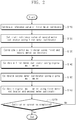
- FIG. 2 is a diagram illustrating an upward range calibration according to the DC voltage function calibration device of FIG. 1 .
- a reference value (10V) which is a DC voltage value, is calibrated with respect to one reference point of the first meter calibrator 110 through a higher standard device (not shown) (operation S110).
- the reference value is set to 10V for convenience of explanation, but it may be set to a DC voltage value other than 10V.
- the DC voltage calibration circuit 140 calibrates the reference point of the second meter calibrator 120 using the reference value of the first meter calibrator 110 (operation S120).
- the DC voltage calibration circuit 140 calibrates the -10V point of the second meter calibrator 120 with the reference value of 10V for the first meter calibrator 110.
- the DC voltage calibration circuit 140 may control through a switch so that the first plus terminal 111 of the first meter calibrator 110 is connected to the second minus terminal 122 of the second meter calibrator 120, and the first minus terminal 112 of the first meter calibrator 110 is connected to the first plus terminal 121 of the second meter calibrator 120.
- the plus terminals 111 and 121 and the minus terminals 112 and 122 of the first meter calibrator 110 and the second meter calibrator 120 are connected to each other.
- the DC voltage calibration circuit 140 calibrates to a point that is twice the reference value of the digital multi meter 130 using the first meter calibrator 110 and the second meter calibrator 120 (operation S130).
- the DC voltage calibration circuit 140 may control the first meter calibrator 110 to output 10V and controls the second meter calibrator 120 to output at -0V, thereby it may set the value of the digital multi meter 130 to 20V.
- operations S110 to S130 are referred to as a method of substitution. This is called the basic calibration of the first meter calibrator 110, the second meter calibrator 120, and the digital multi meter 130.
- the DC voltage calibration circuit 140 calibrates the first meter calibrator 110 with a point that is twice a previously calibrated point, using the digital multi meter 130 (operation S140).
- the DC voltage calibration circuit 140 calibrates the 20V point of the first meter calibrator 110 by controlling the digital multi meter 130 to output at a calibrated 20V.
- the DC voltage calibration circuit 140 calibrates the second meter calibrator 110 with a point that is twice the previously calibrated point, using the digital multi meter 130 (operation S150).
- the DC voltage calibration circuit 140 calibrates the 20V point of the first meter calibrator 110 by controlling the digital multi meter 130 to output at a calibrated -20V.
- the DC voltage calibration circuit 140 calibrates the digital multi meter 130 using the first meter calibrator 110 and the second meter calibrator 120 (operation S160). At this time, when the DC voltage calibration circuit 140 controls the first meter calibrator 110 to output a calibration point of 20V and controls the second meter calibrator 120 to output a calibration point of -20V, it may calibrate the digital multi meter 130 with a 40V point that is twice the previously calibrated point.
- the DC voltage calibration circuit 140 determines whether the calibration operation is completed (operation S170). At this time, the DC voltage calibration circuit 140 ends when the calibration operation is completed.
- the DC voltage calibration circuit 140 proceeds to operation S140. Thereafter, when the DC voltage calibration circuit 140 mutually calibrates the first meter calibrator 110, the second meter calibrator 120, and the digital multi meter 130 by alternating to double points, after the above calibrated 10V, 20V, and 40V points, it may continue to calibrate extended points in the order of 80V and 160V. Because of this, through n-times iterations of a method for extending previously extended points by 2 times to new reference points, it is possible to perform a basic calibration on the first meter calibrator 110, the second meter calibrator 120, and the digital multi meter 130 at a point corresponding to 2 n times.
- the DC voltage calibration circuit 140 when the DC voltage calibration circuit 140 controls the first meter calibrator 110 to output 10V and controls the second meter calibrator 120 to output -20V, it may calibrate the 30V point of the digital multi meter 130. Thereafter, the DC voltage calibration circuit 140 sets the output of the digital multi meter 130 to 30V, thereby it calibrates a point of 30V of the first meter calibrator 110 and the second meter calibrator 120.
- the 40V point of the digital multi meter 130 may be calibrated.
- An extension method in such a manner may calibrate points corresponding to 2 n+1 .
- k and 1 have values of 0, 1, 2, ....
- the combination of the first meter calibrator 110 and the second meter calibrator 120 may be set in various ways according to each extension operation.
- the calibration point P n of n-times extensions may be configured to set one of the multiple obtained from the beginning to the immediately preceding extension operation to the first meter calibrator 110 and the second meter calibrator 120, and since the sum of the first meter calibrator 110 and the second meter calibrator 120 is determined by the digital multi meter 130, it may be expressed by the following Equation 1.
- P n a n + b n P 0
- n is a natural number (1, 2, 3, ).
- a n is a multiple of the first meter calibrator 110 and a positive integer less than or equal to 2 n-1 and b n is a multiple of the second meter calibrator 120 and a positive integer less than or equal to 2 n-1 .
- P 0 is a reference point.
- a calibration value V n of a meter calibrator or the digital multi meter 130 for a calibration point P n may be expressed by the following Equation 2.
- V n a n + b n 1 + ⁇ a n , b n V 0
- ⁇ ( a n , b n ) is a relative correction value of a calibration value for a n +b n combination and V 0 is a reference value of a reference point.
- the interval should be divided and calibrated to units of 10 times the reference voltage.
- the first meter calibrator 110, the second meter calibrator 120, and the digital multi meter 130 calibrate 10V, 30V, 50V, 70V, 90V, and 100V to calibrate the range below 100V.
- the first meter calibrator 110, the second meter calibrator 120, and the digital multi meter 130 calibrate 300V, 500V, 700V, 900V, and 1000V.
- the DC voltage calibration circuit 140 may repeat the operation of calibrating the first meter calibrator 110, the second meter calibrator 120, and the digital multi meter 130.
- FIG. 3 is a flowchart illustrating an exemplary downward calibration operation of a DC voltage in a DC voltage calibration circuit according to an inventive concept.
- a reference value (10V) which is a DC voltage value, is calibrated with respect to one reference point of the first meter calibrator 110 through a higher standard device (not shown) (operation S210).
- the reference value is set to 10V for convenience of explanation, but it may be set to a DC voltage value other than 10V.
- the DC voltage calibration circuit 140 calibrates the reference point of the second meter calibrator 120 using the reference value of the first meter calibrator 110 (operation S220).
- the DC voltage calibration circuit 140 calibrates the -10V point of the second meter calibrator 120 with the reference value of 10V for the first meter calibrator 110.
- the DC voltage calibration circuit 140 may control through a switch so that the first plus terminal 111 of the first meter calibrator 110 is connected to the second minus terminal 122 of the second meter calibrator 120, and the first minus terminal 112 of the first meter calibrator 110 is connected to the first plus terminal 121 of the second meter calibrator 120.
- the plus terminals 111 and 121 and the minus terminals 112 and 122 of the first meter calibrator 110 and the second meter calibrator 120 are connected to each other.
- the DC voltage calibration circuit 140 calibrates to a point that is twice the reference value of the digital multi meter 130 using the first meter calibrator 110 and the second meter calibrator 120 (operation S230). In the connection state as shown in FIG. 1 , the DC voltage calibration circuit 140 controls the first meter calibrator 110 to output 10V and controls the second meter calibrator 120 to output -10V, so that it may set the value of the digital multi meter 130 to 20V.
- the DC voltage calibration circuit 140 sets the first meter calibrator 110 to half of the previous calibration point and measures the set value using the digital multi meter 130 (operation S240).
- the DC voltage calibration circuit 140 sets the first meter calibrator 110 to 5V and controls to output the set value of 5V. Thereafter, the DC voltage calibration circuit 140 measures the output value V1 of the first meter calibrator 110 using the digital multi meter 130.
- the DC voltage calibration circuit 140 sets the second meter calibrator 120 to half of the previous calibration point and measures the set value using the digital multi meter 130 (operation S250).
- the DC voltage calibration circuit 140 sets the second meter calibrator 120 to -5V and controls to output the set value of -5V. Thereafter, the DC voltage calibration circuit 140 measures the output value V1 of the second meter calibrator 120 using the digital multi meter 130.
- the DC voltage calibration circuit 140 sets the input polarity of the digital multi meter 130 to read the bipolar indication value (+5V). Through this, the output values V1 and V2 may be obtained.
- the DC voltage calibration circuit 140 connects the first meter calibrator 110 and the second meter calibrator 120 in series with each other in the opposite polarity and measures the same using the digital multi meter (S240) (operation S260). At this time, a value measured by the digital multi meter 130 is referred to as U3.
- U3 a value measured by the digital multi meter 130
- the output values of the first meter calibrator 110 and the second meter calibrator 120 are defined as unknowns X1 and -X2, respectively.
- X1 and X2 are positive numbers and have a relation of X 1 ⁇ X 2.
- U3(X1 + X2 U3) is obtained.
- Equation 3 X 1 ⁇ X 2 ⁇ V 1 ⁇ V 2
- X1 and X2 may be expressed by the following Equation 4.
- X 1 U 3 + V 1 ⁇ V 2 / 2
- X 2 U 3 ⁇ V 1 + V 2 / 2
- the DC voltage calibration circuit 140 may obtain an output value of 5V of two meter calibrators.
- the DC voltage calibration circuit 140 calibrates the first meter calibrator 110 and the second meter calibrator 120 to half of the previous calibration point using Equation 4 (operation S270). At this time, the DC voltage calibration circuit 140 calibrates a point of 5 V in the first meter calibrator 110 and a point of -5 V in the second meter calibrator 120.
- the DC voltage calibration circuit 140 calibrates the digital multi meter 130 using the first meter calibrator 110 (or the second meter calibrator 120).
- the DC voltage calibration circuit 140 calibrates the first meter calibrator 110, the second meter calibrator 120, and the digital multi meter 130 to 5V, which is half of the reference point.
- the DC voltage calibration circuit 140 determines whether the calibration operation is completed (operation S290). The DC voltage calibration circuit 140 ends when the calibration operation is completed. However, if the calibration operation is not completed, the DC voltage calibration circuit 140 proceeds to operation S240 for downward calibration.
- the first meter calibrator 110, the second meter calibrator 120, and the digital multi meter 130 may calibrate a point corresponding to 1/2 n of the reference point such as 5V, 2.5V, 1.25V, 0.625V, and 0.3125V.
- V 0 a n + b n 1 + ⁇ a n b n v n
- a virtual reference point is set, and the result value obtained by performing the upward calibration from the virtual reference point is compared with the previously calibrated value so that the downward conversion may be performed through correction of the virtual reference point value.
- the initial reference point of 10V may be extended downward to 1V, and when a calibration value of 1V point is obtained, for 3V, 5V, 7V, and 9V points, calibration may be performed by applying the upward extension of FIG. 2 .
- various downward point calibrations may be performed in combination with a low point calibration scheme corresponding to 1/2 n .
- a first downward extension method it may be downward-extended to 5V with an initial reference point of 10V, and then the virtual 1V reference value is upward-extended to 5V (1V -> 2V -> 3V -> 5V) to obtain the final operation d. Then, the calibration value of a 1V point may be obtained by using Equation 6. Then, the calibration values of 2V and 3V may also be calculated using the values obtained in the immediately-preceding performed virtual upward-extension process. Calibrations of 4V, 6V, 7V, 8V, and 9V are possible through upward extension with the combination of 1V, 2V, 3V, and 5V.
- the multifunction meter (or meter calibrator) may perform its own calibration based on one reference point for each function, a wide range of standard retroactive property may be obtained efficiently with low cost and time.
- the calibration described in the inventive concept means that the indication value of the corresponding measurement instrument forms a relationship loop to be retroactive to the upper standard.
- calibration refers to the formation of the standard retroactive relationship, not to the adjustment of the corresponding instrumentation, if necessary, and refers to the operation of obtaining the difference between the indication value and the standard value.
- the high-resolution digital multi meter 130 has lower stability performance than the meter calibrator, there is no performance problem in measuring the first and second meter calibrators 110 and 120 for a short period of time. Therefore, the high resolution of the digital multi meter 130 is utilized only as an intermediary role. For this, the second meter calibrator 120 and the digital multi meter 130 are also calibrated together with the first meter calibrator 110.
- the inventive concept relates to a measurement device, and a DC voltage function calibration device and method of a multifunction meter calibrator that enables calibration of various points for DC voltage may be provided.
Landscapes
- Physics & Mathematics (AREA)
- General Physics & Mathematics (AREA)
- Measurement Of Current Or Voltage (AREA)
Abstract
Description
- The present disclosure relates to a measurement device, and more particularly, to a DC voltage function calibration device and method of a multifunction meter calibrator.
- Multifunction meters and meter calibrators are widely used measuring instruments in future high-tech industries such as smart communications electronics, electric vehicles, and medical diagnostics. Multifunction meters and meter calibrators, for example, are multifunction instruments for measuring DC voltage up to 1 kilovolts (kV), AC voltage of maximum frequency 1 megahertz (Mhz), DC current up to 1 ampere (A), AC current of maximum frequency 10Mhz (megahertz), and resistance up to 1 Gigaohm (GΩ).
- As instruments for calibrating multifunction meters, multifunction meter calibrators may be devices that may calibrate voltage, current, and resistance values within the above-mentioned range for each of the five measurement functions of DC voltage, AC voltage, DC current, AC current, and resistance of the multifunction meter, and may have higher stability than multifunction meters. Conventionally, calibration operation should be done by direct comparison of DC voltage, AC voltage, DC current, AC current, and resistance with the higher national standard using a multifunction meter calibrator.
- However, the multifunction meter calibrator must be calibrated at various points (measured DC voltage, AC voltage, DC current, AC current, and resistance) for calibration depending on the function. When calibrating at various points about the DC voltage calibrated to this multifunction meter calibrator (or multifunction meter), as the number of points for calibration (DC voltages) increases, more time and more cost are required.
- The present disclosure is to provide a DC voltage function calibration device and method for a multifunction meter and meter calibrator that may save time and money for calibration of various points on the DC voltage.
- The present disclosure is also to provide a DC voltage function calibration device and method for calibrating a wide range of points for the DC voltage of a multifunction meter calibrator.
- According to the inventive concept, a DC voltage function calibration device includes: a first meter calibrator configured to be calibrated to a reference value for a reference point and having a first plus terminal and a first minus terminal; a second meter calibrator configured to be calibrated to the reference value for the reference point and having a second plus terminal and a second minus terminal connected to the first minus terminal; a digital multi meter having a third plus terminal connected to the first plus terminal and a third minus terminal connected to the second plus terminal; and a DC voltage calibration circuit configured to control to calibrate a DC voltage for other points through up-converting or down-converting a voltage value using the digital multi meter based on the reference value set in the first meter calibrator and the second meter calibrator.
- In an embodiment, when the DC voltage calibration circuit is calibrated with a reference value as a reference value through a higher standard device for one of the first meter calibrator and the second meter calibrator, the first plus terminal may be connected to the second minus terminal and the second minus terminal may be connected to the first plus terminal to calibrate a voltage of a minus polarity to another meter calibrator.
- In an embodiment, the DC voltage calibration circuit may upward-extend the plus polarity point of the third plus terminal and the minus polarity point of the third minus terminal of the digital multi meter through calibration with a combination voltage as a reference of an extension point with respect to a voltage calibrated to the first meter calibrator and the second meter calibrator.
- In an embodiment, the DC voltage calibration circuit may calibrate points corresponding to 2n times or 2n+1 times with respect to the reference value through n-times iterations of an operation according to an upward extension.
- In an embodiment, the DC voltage calibration circuit may determine as a virtual reference point a low point corresponding to dividing a minimum point by an integer multiple among the points calibrated to the first meter calibrator and the second meter calibrator, compare the value obtained through the upward extension with the reference value of the minimum point to obtain a state deviation, and calibrate a virtual reference value assigned to the virtual reference point by the state deviation to calibrate the virtual reference point.
- In an embodiment, the DC voltage calibration circuit may measure the combination voltage of the first meter calibrator and the second meter calibrator using the digital multi meter, and downward-extend a point corresponding to half the minimum point through calibration after measuring a difference voltage between the first meter calibrator and the second meter calibrator, through a calculation of the output value of the first meter calibrator and the second meter calibrator from the combination voltage and the difference voltage.
- In an embodiment, the DC voltage calibration circuit may calibrate points corresponding to 1/2n times with respect to the reference value through n-times iterations of an operation according to the downward expansion.
- According to the inventive concept, a DC voltage function calibration method includes: calibrating a reference point as a reference value through a higher standard device for one of a first meter calibrator and a second meter calibrator; connecting a first plus terminal of a first meter calibrator to a second minus terminal of the second meter calibrator and connecting a second plus terminal of the second meter calibrator to a first minus terminal of the first meter calibrator to calibrate a voltage of a minus polarity to another meter calibrator; connecting the first plus terminal to a third plus terminal of a digital multi meter, connecting the second plus terminal to a third minus terminal of the digital multi meter, and connecting the first minus terminal to the second minus terminal; calibrating a plus polarity point and a minus polarity point of a digital multi meter based on a combination point as a reference of an extension point with respect to a voltage calibrated to the first meter calibrator and the second meter calibrator; and calibrating a DC voltage for other points through up-converting or down-converting a voltage value using the digital multi meter based on the reference value set in the first meter calibrator and the second meter calibrator.
- In an embodiment, the controlling to calibrate the DC voltage for the other points through the up-converting may include upward-extending the plus polarity point of the third plus terminal and the minus polarity point of the third minus terminal of the digital multi meter based on a combination voltage as an extension point through an iteration of a calibration operation with respect to the voltage calibrated to the first meter calibrator and the second meter calibrator.
- In an embodiment, the controlling to calibrate the DC voltage for the other points through the up-converting may include: determining as a virtual reference point a low point corresponding to dividing a minimum point by an integer multiple among the points calibrated to the first meter calibrator and the second meter calibrator; comparing the value obtained through the upward extension with the reference value of the minimum point to obtain a state deviation; and calibrating a virtual reference value assigned to the virtual reference point by the state deviation to calibrate the virtual reference point.
- In an embodiment, the controlling to calibrate the DC voltage for the other points through the down-converting may include: measuring the combination voltage of the first meter calibrator and the second meter calibrator using the digital multi meter; measuring a difference voltage between the first meter calibrator and the second meter calibrator; and downward-extending a point corresponding to half the minimum point through calibration through a calculation of the output value of the first meter calibrator and the second meter calibrator from the combination voltage and the difference voltage.
- In relation to the DC voltage function calibration method of the inventive concept, when calibration is performed based on one reference point according to the function, since a wide range of points may be calibrated to meet standards, this saves time and money for DC voltage calibration.
-
-
FIG. 1 is a diagram illustrating a structure of a DC voltage function calibration device of a multifunction meter calibrator according to an inventive concept. -
FIG. 2 is a flowchart illustrating an exemplary upward calibration operation of a DC voltage in a DC voltage calibration circuit according to an inventive concept. -
FIG. 3 is a flowchart illustrating an exemplary downward calibration operation of a DC voltage in a DC voltage calibration circuit according to an inventive concept. -
FIG. 1 shows the best mode for the implementation of the inventive concept. - Hereinafter, preferred embodiments of the inventive concept will be described in more detail with reference to the accompanying drawings. In the description below, it should be noted that only parts necessary for understanding operations according to the inventive concept are described and descriptions of other parts are omitted not to obscure the scope of the inventive concept.
- The inventive concept provides a DC voltage function calibration device and method for calibrating the DC voltage of a multifunction meter and a multifunction meter calibrator. In the following description, for convenience of explanation, a meter calibrator (i.e., a multifunction meter calibrator) will be described and when using a multifunction meter instead of a multifunction meter calibrator, the DC voltage of the multifunction meter may be calibrated.
-
FIG. 1 is a diagram illustrating a structure of a DC voltage function calibration device of a multifunction meter calibrator according to an inventive concept. - Referring to
FIG. 1 , a DC voltagefunction calibration device 100 includes first andsecond meter calibrators multi meter 130, and a DCvoltage calibration circuit 140. - The
first meter calibrator 110 includes a first plus (+)terminal 111 and a first minus (-)terminal 112. - The
second meter calibrator 120 includes asecond plug terminal 121 and asecond minus terminal 122. Here, thefirst minus terminal 112 of thefirst meter calibrator 110 and thesecond minus terminal 122 of thesecond meter calibrator 120 are connected to each other. - The digital
multi meter 130 includes athird plus terminal 131 and athird minus terminal 132. At this time, thethird plus terminal 131 is connected to thefirst plus terminal 111 of thefirst meter calibrator 110 and thethird minus terminal 132 is connected to thesecond plus terminal 121 of thesecond meter calibrator 120. The digitalmulti meter 130 may be a high resolution digital multi meter. - The DC
voltage calibration circuit 140 is connected to the first andsecond meter calibrators multi meter 130. Through this, the DCvoltage calibration circuit 140 controls a point calibration to a DV voltage value inputted through theplus terminals minus terminals second meter calibrators multi meter 130. - Moreover, the first and
second meter calibrators multi meter 130 is a device to measure a wide range of DC voltage, and the measurement range of DC voltage is divided into multiple decimal intervals, such as -100mV to 100mV, -1V to 1V, -10V to 10V, -100V to 100V, and -1000V to 1000V (or -220mV to 220mV, -2.2V to 2.2V, -22V to 22V, -220V to 220V, and -1000V to 1000V). - For example, a reference value for the reference point of the
first meter calibrator 110 may be given as 10V, for example. However, 10V, which is the reference value for the reference point, is illustratively described, and may be set to various values other than 10V. At this time, the reference value is set based on a higher standard device for example, such as a Zener standard device which is a device provided by a higher standard authority. Thereafter, the reference point of the negative reference value (-10V) may be calibrated through the digitalmulti meter 130 based on thefirst meter calibrator 110. The digitalmulti meter 130 calibrates the reference point with a reference value of 10V through thefirst meter calibrator 110 and calibrates thesecond meter calibrator 120 using the digitalmulti meter 130. - In the following, the calibration for the upper range and the calibration for the lower range will be described for the DC voltage based on the reference point. Hereinafter, for convenience of explanation, it is described that indication values of the
first meter calibrator 110 and the digitalmulti meter 130 have a positive polarity and an indication value of thesecond meter calibrator 120 has a negative polarity. However, thefirst meter calibrator 110, thesecond meter calibrator 120, and the digitalmulti meter 130 may be configured to have different polarities depending on the implementation. - First, one reference point that meets the standard is calibrated for one of the first and
second meter calibrators - First, the DC
voltage calibration circuit 140 sets one of the previously calibrated points to thefirst meter calibrator 110 and thesecond meter calibrator 120 to have a positive polarity and a negative polarity, respectively. Thereafter, the DCvoltage calibration circuit 140 calibrates the extension point of the digitalmulti meter 130 using the combined voltage of thefirst meter calibrator 110 and thesecond meter calibrator 120 as a reference of the extension point. The DCvoltage calibration circuit 140 may calibrate the positive polarity point of thefirst meter calibrator 110 and the negative polarity point of thesecond meter calibrator 120 based on the extension point of the digitalmulti meter 130. - Second, the DC
voltage calibration circuit 140 sets one of the previously calibrated points to thefirst meter calibrator 110 and thesecond meter calibrator 120 to have a positive polarity and a negative polarity, respectively. The DCvoltage calibration circuit 140 measures the combined voltage of the polarities set in thefirst meter calibrator 110 and thesecond meter calibrator 120 as the value of the calibrated digitalmulti meter 130, and after measuring the difference voltage between thefirst meter calibrator 110 and thesecond meter calibrator 120, calculates the output of two meter calibrators from the sum voltage and the difference voltage value to calibrate a point that is half the minimum point. - Third, the DC
voltage calibration circuit 140 determines a low point corresponding to dividing a minimum point among previously calibrated points by an integer multiple, as a virtual reference point. The DCvoltage calibration circuit 140 temporarily assigns the determined reference point as a virtual reference value, and obtains a relative deviation by comparing the value obtained by performing the upward extension calibration process described first from the virtual reference point to the minimum point with the reference value of the minimum point. The DCvoltage calibration circuit 140 may calibrate a virtual reference value assigned to the virtual reference point by the relative deviation to calibrate the virtual reference point. - When the DC
voltage calibration circuit 140, for example, calibrates the DC voltage value through a higher standard device for one point of thefirst meter calibrator 110, it may calibrate the multiple points of thefirst meter calibrator 110 and the multiple points of thesecond meter calibrator 120 and the digitalmulti meter 130 through up or down conversion. - Through this, since it is possible to calibrate other points using one point of calibration without having to calibrate all the points using a higher standard device, time and cost for calibrating the DC voltage function of a meter calibrator (or multifunction meter, multifunction meter calibrator) may be saved.
-
FIG. 2 is a diagram illustrating an upward range calibration according to the DC voltage function calibration device ofFIG. 1 . - Referring to
FIG. 2 , a reference value (10V), which is a DC voltage value, is calibrated with respect to one reference point of thefirst meter calibrator 110 through a higher standard device (not shown) (operation S110). Here, the reference value is set to 10V for convenience of explanation, but it may be set to a DC voltage value other than 10V. - The DC
voltage calibration circuit 140 calibrates the reference point of thesecond meter calibrator 120 using the reference value of the first meter calibrator 110 (operation S120). The DCvoltage calibration circuit 140 calibrates the -10V point of thesecond meter calibrator 120 with the reference value of 10V for thefirst meter calibrator 110. At this time, the DCvoltage calibration circuit 140 may control through a switch so that thefirst plus terminal 111 of thefirst meter calibrator 110 is connected to thesecond minus terminal 122 of thesecond meter calibrator 120, and thefirst minus terminal 112 of thefirst meter calibrator 110 is connected to thefirst plus terminal 121 of thesecond meter calibrator 120. Through this, theplus terminals minus terminals first meter calibrator 110 and thesecond meter calibrator 120 are connected to each other. - The DC
voltage calibration circuit 140 calibrates to a point that is twice the reference value of the digitalmulti meter 130 using thefirst meter calibrator 110 and the second meter calibrator 120 (operation S130). In the connection state as shown inFIG. 1 , the DCvoltage calibration circuit 140 may control thefirst meter calibrator 110 to output 10V and controls thesecond meter calibrator 120 to output at -0V, thereby it may set the value of the digitalmulti meter 130 to 20V. At this time, when a voltage of 10V is inputted through thethird plus terminal 131 of the digitalmulti meter 130, and a voltage of -10V is inputted through thethird minus terminal 132, since they are inputs through the third minus terminal 133 having a negative polarity, they may become 10V and the combined output may become 20V. - Here, operations S110 to S130 are referred to as a method of substitution. This is called the basic calibration of the
first meter calibrator 110, thesecond meter calibrator 120, and the digitalmulti meter 130. - The DC
voltage calibration circuit 140 calibrates thefirst meter calibrator 110 with a point that is twice a previously calibrated point, using the digital multi meter 130 (operation S140). The DCvoltage calibration circuit 140 calibrates the 20V point of thefirst meter calibrator 110 by controlling the digitalmulti meter 130 to output at a calibrated 20V. - The DC
voltage calibration circuit 140 calibrates thesecond meter calibrator 110 with a point that is twice the previously calibrated point, using the digital multi meter 130 (operation S150). The DCvoltage calibration circuit 140 calibrates the 20V point of thefirst meter calibrator 110 by controlling the digitalmulti meter 130 to output at a calibrated -20V. - The DC
voltage calibration circuit 140 calibrates the digitalmulti meter 130 using thefirst meter calibrator 110 and the second meter calibrator 120 (operation S160). At this time, when the DCvoltage calibration circuit 140 controls thefirst meter calibrator 110 to output a calibration point of 20V and controls thesecond meter calibrator 120 to output a calibration point of -20V, it may calibrate the digitalmulti meter 130 with a 40V point that is twice the previously calibrated point. The DCvoltage calibration circuit 140 determines whether the calibration operation is completed (operation S170). At this time, the DCvoltage calibration circuit 140 ends when the calibration operation is completed. - However, if the calibration operation is not completed, the DC
voltage calibration circuit 140 proceeds to operation S140. Thereafter, when the DCvoltage calibration circuit 140 mutually calibrates thefirst meter calibrator 110, thesecond meter calibrator 120, and the digitalmulti meter 130 by alternating to double points, after the above calibrated 10V, 20V, and 40V points, it may continue to calibrate extended points in the order of 80V and 160V. Because of this, through n-times iterations of a method for extending previously extended points by 2 times to new reference points, it is possible to perform a basic calibration on thefirst meter calibrator 110, thesecond meter calibrator 120, and the digitalmulti meter 130 at a point corresponding to 2n times. - Unlike this, in operation S160, when the DC
voltage calibration circuit 140 controls thefirst meter calibrator 110 to output 10V and controls thesecond meter calibrator 120 to output -20V, it may calibrate the 30V point of the digitalmulti meter 130. Thereafter, the DCvoltage calibration circuit 140 sets the output of the digitalmulti meter 130 to 30V, thereby it calibrates a point of 30V of thefirst meter calibrator 110 and thesecond meter calibrator 120. When thefirst meter calibrator 110 is controlled to output 10V and thesecond meter calibrator 120 is controlled to output -30V, the 40V point of the digitalmulti meter 130 may be calibrated. An extension method in such a manner may calibrate points corresponding to 2n+1. - Through this, it is possible to extend at a k-times interval of the reference point and to calibrate points corresponding to kn+1 times of the reference point. Here, k and 1 have values of 0, 1, 2, ....
- As an example of the above-described operation, the combination of the
first meter calibrator 110 and thesecond meter calibrator 120 may be set in various ways according to each extension operation. The calibration point Pn of n-times extensions may be configured to set one of the multiple obtained from the beginning to the immediately preceding extension operation to thefirst meter calibrator 110 and thesecond meter calibrator 120, and since the sum of thefirst meter calibrator 110 and thesecond meter calibrator 120 is determined by the digitalmulti meter 130, it may be expressed by the following Equation 1.
- Here, n is a natural number (1, 2, 3, ...). an is a multiple of the
first meter calibrator 110 and a positive integer less than or equal to 2n-1 and bn is a multiple of thesecond meter calibrator 120 and a positive integer less than or equal to 2n-1. P0 is a reference point. - When an equation for the extended voltage value is expressed from Equation 1, a calibration value Vn of a meter calibrator or the digital
multi meter 130 for a calibration point Pn may be expressed by the following Equation 2.
- Here, δ(an ,bn ) is a relative correction value of a calibration value for an+bn combination and V0 is a reference value of a reference point.
- Since the measurement ranges of the
first meter calibrator 110, thesecond meter calibrator 120, and the digitalmulti meter 130 are divided into decimal intervals such as 10V or less, 100V or less, and 1000V or less, the interval should be divided and calibrated to units of 10 times the reference voltage. - For example, when the DC
voltage calibration circuit 140 calibrates 10V to the initial reference voltage, thefirst meter calibrator 110, thesecond meter calibrator 120, and the digitalmulti meter 130 calibrate 10V, 30V, 50V, 70V, 90V, and 100V to calibrate the range below 100V. Here, when the DCvoltage calibration circuit 140 sets the calibrated 100V to the reference voltage, thefirst meter calibrator 110, thesecond meter calibrator 120, and the digitalmulti meter 130 calibrate 300V, 500V, 700V, 900V, and 1000V. In such a manner, for the next interval, by using the maximum point of the immediately preceding interval as the new reference point, the DCvoltage calibration circuit 140 may repeat the operation of calibrating thefirst meter calibrator 110, thesecond meter calibrator 120, and the digitalmulti meter 130. -
FIG. 3 is a flowchart illustrating an exemplary downward calibration operation of a DC voltage in a DC voltage calibration circuit according to an inventive concept. - Referring to
FIG. 3 , a reference value (10V), which is a DC voltage value, is calibrated with respect to one reference point of thefirst meter calibrator 110 through a higher standard device (not shown) (operation S210). Here, the reference value is set to 10V for convenience of explanation, but it may be set to a DC voltage value other than 10V. - The DC
voltage calibration circuit 140 calibrates the reference point of thesecond meter calibrator 120 using the reference value of the first meter calibrator 110 (operation S220). The DCvoltage calibration circuit 140 calibrates the -10V point of thesecond meter calibrator 120 with the reference value of 10V for thefirst meter calibrator 110. At this time, the DCvoltage calibration circuit 140 may control through a switch so that thefirst plus terminal 111 of thefirst meter calibrator 110 is connected to thesecond minus terminal 122 of thesecond meter calibrator 120, and thefirst minus terminal 112 of thefirst meter calibrator 110 is connected to thefirst plus terminal 121 of thesecond meter calibrator 120. Through this, theplus terminals minus terminals first meter calibrator 110 and thesecond meter calibrator 120 are connected to each other. - The DC
voltage calibration circuit 140 calibrates to a point that is twice the reference value of the digitalmulti meter 130 using thefirst meter calibrator 110 and the second meter calibrator 120 (operation S230). In the connection state as shown inFIG. 1 , the DCvoltage calibration circuit 140 controls thefirst meter calibrator 110 to output 10V and controls thesecond meter calibrator 120 to output -10V, so that it may set the value of the digitalmulti meter 130 to 20V. At this time, when a voltage of 10V is inputted through thethird plus terminal 131 of the digitalmulti meter 130, and a voltage of -10 V is inputted through thethird minus terminal 132, since they are inputs through thethird minus terminal 132 having a negative polarity, they may become 10V and the combined output may become 20V. - The DC
voltage calibration circuit 140 sets thefirst meter calibrator 110 to half of the previous calibration point and measures the set value using the digital multi meter 130 (operation S240). The DCvoltage calibration circuit 140 sets thefirst meter calibrator 110 to 5V and controls to output the set value of 5V. Thereafter, the DCvoltage calibration circuit 140 measures the output value V1 of thefirst meter calibrator 110 using the digitalmulti meter 130. - The DC
voltage calibration circuit 140 sets thesecond meter calibrator 120 to half of the previous calibration point and measures the set value using the digital multi meter 130 (operation S250). The DCvoltage calibration circuit 140 sets thesecond meter calibrator 120 to -5V and controls to output the set value of -5V. Thereafter, the DCvoltage calibration circuit 140 measures the output value V1 of thesecond meter calibrator 120 using the digitalmulti meter 130. - The DC
voltage calibration circuit 140 sets the input polarity of the digitalmulti meter 130 to read the bipolar indication value (+5V). Through this, the output values V1 and V2 may be obtained. - The DC
voltage calibration circuit 140 connects thefirst meter calibrator 110 and thesecond meter calibrator 120 in series with each other in the opposite polarity and measures the same using the digital multi meter (S240) (operation S260). At this time, a value measured by the digitalmulti meter 130 is referred to as U3. For example, when thefirst meter calibrator 110 is set to 5V and thesecond meter calibrator 120 is set to -5V, the output values of thefirst meter calibrator 110 and thesecond meter calibrator 120 are defined as unknowns X1 and -X2, respectively. X1 and X2 are positive numbers and have a relation of X1≃X2. When the values of X1 and X2 are added, U3(X1 + X2 = U3) is obtained. Generally, the difference between the values of the first andsecond meter calibrators multi meter 130 having a high resolution is excellent. This may be expressed by the following Equation 3.
- Through this, X1 and X2 may be expressed by the following Equation 4.

- Using Equation 4, the DC
voltage calibration circuit 140 may obtain an output value of 5V of two meter calibrators. - The DC
voltage calibration circuit 140 calibrates thefirst meter calibrator 110 and thesecond meter calibrator 120 to half of the previous calibration point using Equation 4 (operation S270). At this time, the DCvoltage calibration circuit 140 calibrates a point of 5 V in thefirst meter calibrator 110 and a point of -5 V in thesecond meter calibrator 120. - The DC
voltage calibration circuit 140 calibrates the digitalmulti meter 130 using the first meter calibrator 110 (or the second meter calibrator 120). - Through this, the DC
voltage calibration circuit 140 calibrates thefirst meter calibrator 110, thesecond meter calibrator 120, and the digitalmulti meter 130 to 5V, which is half of the reference point. - The DC
voltage calibration circuit 140 determines whether the calibration operation is completed (operation S290). The DCvoltage calibration circuit 140 ends when the calibration operation is completed. However, if the calibration operation is not completed, the DCvoltage calibration circuit 140 proceeds to operation S240 for downward calibration. - In such a way, if the above downward extension process is repeated n times using the point that is downward-extended in the previous operation as a new reference point, by extending the calibration point downward by half the previous calibration point, the
first meter calibrator 110, thesecond meter calibrator 120, and the digitalmulti meter 130 may calibrate a point corresponding to 1/2n of the reference point such as 5V, 2.5V, 1.25V, 0.625V, and 0.3125V. - On the other hand, if Equation 2 is set inversely, a point corresponding to dividing the reference point Po corresponding to the initial reference value V0 for downward extension by an integer multiple is determined as a downward calibration point, and the downward calibration point is set to the reference point P-n, and then, the value is defined as X. It selects the upward extension method to generate the scaling integer values of the reference points P0 and P-n, and determines the extension number n and the extension constants an and bn. An arbitrary predicted value is determined to be a virtual reference value by the X value (e.g., determine the correction value of the digital
multi meter 130 as 0), and n-times extended calibration of Equation 2 is performed. At this time, the value Y extended from the virtual reference value X may be expressed by the following Equation 5.
- If the virtual reference point value X is correct, the value of Y should be the original reference value V0. That is, if the actual value of the desired downward calibration point P-n is defined as vn, the following Equation 6 is established.

- If there is a difference between Y and V0, the difference value may be obtained. If the relative difference is determined as d, the following Equation 7 is established.

- Through this, Equation 8 below may be obtained.

- When assuming that the actual value of the downward calibration point P-n to be calibrated is vn, the following Equation 9 may be obtained.

- In such a way, a virtual reference point is set, and the result value obtained by performing the upward calibration from the virtual reference point is compared with the previously calibrated value so that the downward conversion may be performed through correction of the virtual reference point value. For example, the initial reference point of 10V may be extended downward to 1V, and when a calibration value of 1V point is obtained, for 3V, 5V, 7V, and 9V points, calibration may be performed by applying the upward extension of
FIG. 2 . Alternatively, various downward point calibrations may be performed in combination with a low point calibration scheme corresponding to 1/2n. For example, as a first downward extension method, it may be downward-extended to 5V with an initial reference point of 10V, and then the virtual 1V reference value is upward-extended to 5V (1V -> 2V -> 3V -> 5V) to obtain the final operation d. Then, the calibration value of a 1V point may be obtained by using Equation 6. Then, the calibration values of 2V and 3V may also be calculated using the values obtained in the immediately-preceding performed virtual upward-extension process. Calibrations of 4V, 6V, 7V, 8V, and 9V are possible through upward extension with the combination of 1V, 2V, 3V, and 5V. - In the inventive concept, since the multifunction meter (or meter calibrator) may perform its own calibration based on one reference point for each function, a wide range of standard retroactive property may be obtained efficiently with low cost and time. The calibration described in the inventive concept means that the indication value of the corresponding measurement instrument forms a relationship loop to be retroactive to the upper standard. In the inventive concept, calibration refers to the formation of the standard retroactive relationship, not to the adjustment of the corresponding instrumentation, if necessary, and refers to the operation of obtaining the difference between the indication value and the standard value.
- Through this, in the inventive concept, although the high-resolution digital
multi meter 130 has lower stability performance than the meter calibrator, there is no performance problem in measuring the first andsecond meter calibrators multi meter 130 is utilized only as an intermediary role. For this, thesecond meter calibrator 120 and the digitalmulti meter 130 are also calibrated together with thefirst meter calibrator 110. - Although the exemplary embodiments of the inventive concept have been described, it is understood that the inventive concept should not be limited to these exemplary embodiments but various changes and modifications can be made by one ordinary skilled in the art within the spirit and scope of the inventive concept as hereinafter claimed.
- The inventive concept relates to a measurement device, and a DC voltage function calibration device and method of a multifunction meter calibrator that enables calibration of various points for DC voltage may be provided.
Claims (11)
- A DC voltage function calibration device comprising:a first meter calibrator configured to be calibrated to a reference value for a reference point and having a first plus terminal and a first minus terminal;a second meter calibrator configured to be calibrated to the reference value for the reference point and having a second plus terminal and a second minus terminal connected to the first minus terminal;a digital multi meter having a third plus terminal connected to the first plus terminal and a third minus terminal connected to the second plus terminal; anda DC voltage calibration circuit configured to control to calibrate a DC voltage for other points through up-converting or down-converting a voltage value using the digital multi meter based on the reference value set in the first meter calibrator and the second meter calibrator.
- The DC voltage function calibration device of claim 1, wherein when the DC voltage calibration circuit is calibrated with a reference value as a reference value through a higher standard device for one of the first meter calibrator and the second meter calibrator, the first plus terminal is connected to the second minus terminal and the second minus terminal is connected to the first plus terminal to calibrate a voltage of a minus polarity to another meter calibrator.
- The DC voltage function calibration device of claim 2, wherein the DC voltage calibration circuit upward-extends the plus polarity point of the third plus terminal and the minus polarity point of the third minus terminal of the digital multi meter through calibration with a combination voltage as a reference of an extension point with respect to a voltage calibrated to the first meter calibrator and the second meter calibrator.
- The DC voltage function calibration device of claim 3, wherein the DC voltage calibration circuit calibrates points corresponding to 2n times or 2n+1 times with respect to the reference value through n-times iterations of an operation according to a upward extension.
- The DC voltage function calibration device of claim 4, wherein the DC voltage calibration circuit determines as a virtual reference point a low point corresponding to dividing a minimum point by an integer multiple among the points calibrated to the first meter calibrator and the second meter calibrator, compares the value obtained through the upward extension with the reference value of the minimum point to obtain a state deviation, and calibrates a virtual reference value assigned to the virtual reference point by the state deviation to calibrate the virtual reference point.
- The DC voltage function calibration device of claim 2, wherein the DC voltage calibration circuit measures the combination voltage of the first meter calibrator and the second meter calibrator using the digital multi meter, and downward-extends a point corresponding to half the minimum point through calibration after measuring a difference voltage between the first meter calibrator and the second meter calibrator, through a calculation of the output value of the first meter calibrator and the second meter calibrator from the combination voltage and the difference voltage.
- The DC voltage function calibration device of claim 6, wherein the DC voltage calibration circuit calibrates points corresponding to 1/2n times with respect to the reference value through n-times iterations of an operation according to the downward expansion.
- A DC voltage function calibration method comprising:calibrating a reference point as a reference value through a higher standard device for one of a first meter calibrator and a second meter calibrator;connecting a first plus terminal of a first meter calibrator to a second minus terminal of the second meter calibrator and connecting a second plus terminal of the second meter calibrator to a first minus terminal of the first meter calibrator to calibrate a voltage of a minus polarity to another meter calibrator;connecting the first plus terminal to a third plus terminal of a digital multi meter, connecting the second plus terminal to a third minus terminal of the digital multi meter, and connecting the first minus terminal to the second minus terminal;calibrating a plus polarity point and a minus polarity point of a digital multi meter based on a combination point as a reference of an extension point with respect to a voltage calibrated to the first meter calibrator and the second meter calibrator; andcalibrating a DC voltage for other points through up-converting or down-converting a voltage value using the digital multi meter based on the reference value set in the first meter calibrator and the second meter calibrator.
- The DC voltage function calibration method of claim 8, wherein the controlling to calibrate the DC voltage for the other points through the up-converting comprises upward-extending the plus polarity point of the third plus terminal and the minus polarity point of the third minus terminal of the digital multi meter based on a combination voltage as an extension point through an iteration of a calibration operation with respect to the voltage calibrated to the first meter calibrator and the second meter calibrator.
- The DC voltage function calibration method of claim 9, wherein the controlling to calibrate the DC voltage for the other points through the up-converting comprises:determining as a virtual reference point a low point corresponding to dividing a minimum point by an integer multiple among the points calibrated to the first meter calibrator and the second meter calibrator;comparing the value obtained through the upward extension with the reference value of the minimum point to obtain a state deviation; andcalibrating a virtual reference value assigned to the virtual reference point by the state deviation to calibrate the virtual reference point.
- The DC voltage function calibration method of claim 8, wherein the controlling to calibrate the DC voltage for the other points through the down-converting comprises:measuring the combination voltage of the first meter calibrator and the second meter calibrator using the digital multi meter;measuring a difference voltage between the first meter calibrator and the second meter calibrator; anddownward-extending a point corresponding to half the minimum point through calibration through a calculation of the output value of the first meter calibrator and the second meter calibrator from the combination voltage and the difference voltage.
Applications Claiming Priority (2)
| Application Number | Priority Date | Filing Date | Title |
|---|---|---|---|
| KR1020160035448A KR101893916B1 (en) | 2016-03-24 | 2016-03-24 | Apparatus and method for calibrating direct current voltage functions |
| PCT/KR2017/000747 WO2017164502A1 (en) | 2016-03-24 | 2017-01-23 | Direct current voltage function calibration device and method |
Publications (3)
| Publication Number | Publication Date |
|---|---|
| EP3435106A1 true EP3435106A1 (en) | 2019-01-30 |
| EP3435106A4 EP3435106A4 (en) | 2019-08-14 |
| EP3435106B1 EP3435106B1 (en) | 2022-05-04 |
Family
ID=59900582
Family Applications (1)
| Application Number | Title | Priority Date | Filing Date |
|---|---|---|---|
| EP17770473.1A Active EP3435106B1 (en) | 2016-03-24 | 2017-01-23 | Direct current voltage function calibration device and method |
Country Status (4)
| Country | Link |
|---|---|
| EP (1) | EP3435106B1 (en) |
| KR (1) | KR101893916B1 (en) |
| CN (1) | CN108885247B (en) |
| WO (1) | WO2017164502A1 (en) |
Cited By (1)
| Publication number | Priority date | Publication date | Assignee | Title |
|---|---|---|---|---|
| TWI697678B (en) * | 2019-07-26 | 2020-07-01 | 群光電能科技股份有限公司 | Expandable combination electric meter |
Families Citing this family (2)
| Publication number | Priority date | Publication date | Assignee | Title |
|---|---|---|---|---|
| CN110471023B (en) * | 2019-08-02 | 2025-01-07 | 珠海科盈自动化系统有限公司 | A DC instrument testing tool and method |
| CN112924915B (en) * | 2021-01-27 | 2023-11-21 | 云南电网有限责任公司电力科学研究院 | A voltage monitor mutual calibration system and method |
Family Cites Families (10)
| Publication number | Priority date | Publication date | Assignee | Title |
|---|---|---|---|---|
| JPH0628340B2 (en) * | 1985-12-24 | 1994-04-13 | ソニ−・テクトロニクス株式会社 | Calibration method for analog / digital converter |
| CN1016103B (en) * | 1987-01-29 | 1992-04-01 | 约翰弗兰克制造公司 | The apparatus and method of correcting electric measuring calibrating device internally |
| JPH07104406B2 (en) * | 1989-12-28 | 1995-11-13 | シャープ株式会社 | Digital measuring instrument automatic calibration system |
| JPH04151566A (en) * | 1990-10-15 | 1992-05-25 | Advantest Corp | Calibrating method for dc testing apparatus |
| KR20110098036A (en) * | 2010-02-26 | 2011-09-01 | 한국표준과학연구원 | Digital multimeter calibration technology using internet |
| KR101086342B1 (en) * | 2010-03-23 | 2011-11-23 | 한전케이피에스 주식회사 | Multimeter Calibration Device |
| KR20110010655A (en) * | 2011-01-03 | 2011-02-01 | 김동환 | Dice Bump Game and Its Programs |
| CN202330685U (en) * | 2011-11-16 | 2012-07-11 | 贵州航天计量测试技术研究所 | Device for calibrating electromotive force value of standard battery |
| US9494671B2 (en) * | 2013-11-08 | 2016-11-15 | Advantest Corporation | Method and apparatus for improving differential direct (DC) measurement accuracy |
| CN104236448B (en) * | 2014-09-11 | 2016-11-02 | 湖北航天技术研究院计量测试技术研究所 | Calibration method of electronic standard analog dependent variable calibrator |
-
2016
- 2016-03-24 KR KR1020160035448A patent/KR101893916B1/en active Active
-
2017
- 2017-01-23 WO PCT/KR2017/000747 patent/WO2017164502A1/en not_active Ceased
- 2017-01-23 CN CN201780019284.0A patent/CN108885247B/en active Active
- 2017-01-23 EP EP17770473.1A patent/EP3435106B1/en active Active
Cited By (1)
| Publication number | Priority date | Publication date | Assignee | Title |
|---|---|---|---|---|
| TWI697678B (en) * | 2019-07-26 | 2020-07-01 | 群光電能科技股份有限公司 | Expandable combination electric meter |
Also Published As
| Publication number | Publication date |
|---|---|
| KR101893916B1 (en) | 2018-09-04 |
| EP3435106A4 (en) | 2019-08-14 |
| CN108885247A (en) | 2018-11-23 |
| EP3435106B1 (en) | 2022-05-04 |
| WO2017164502A1 (en) | 2017-09-28 |
| KR20170113744A (en) | 2017-10-13 |
| CN108885247B (en) | 2021-01-26 |
Similar Documents
| Publication | Publication Date | Title |
|---|---|---|
| EP3435106B1 (en) | Direct current voltage function calibration device and method | |
| CN106685188B (en) | Parameter setting circuit of power conversion device and current generation method | |
| CN104111432A (en) | Calibration Of Test Instrument Over Extended Operating Range | |
| CN101535818B (en) | Method and device for measuring voltage on a conductor | |
| KR100634924B1 (en) | Low Power Adjustable Input Threshold Circuit | |
| CN110011661B (en) | Semiconductor device and test method | |
| JP2006184047A (en) | Method for measuring FET characteristics | |
| CN102422538B (en) | Analog unit | |
| US20090195430A1 (en) | Analog-to-digital converting apparatus with lower temperature dependence | |
| CN116908763A (en) | Sectional correction method and system for sampling current | |
| JPWO2006118244A1 (en) | FET characteristics measurement system | |
| US10275064B2 (en) | In cell touch display device and common voltage generating method thereof | |
| Sardjono et al. | Calibration process quantity reduction of the thermal voltage converter standard using a three-stage build-up and build-down method | |
| CN114978163A (en) | Frequency discrimination circuit, clock correction circuit, chip and information processing device | |
| KR100248918B1 (en) | Device and method for measuring output resistance of driver ic | |
| CN217183278U (en) | Frequency discrimination circuit, clock correction circuit, chip and information processing device | |
| KR101888663B1 (en) | Apparatus and mehtod for calibrating direct current function | |
| CN111010180A (en) | An analog-to-digital converter calibration system and method | |
| Galliana et al. | Automated setup to accurately calibrate electrical dc voltage generators | |
| US7050919B1 (en) | Method and apparatus for autocalibrating a plurality of phase-delayed clock signal edges within a reference clock period | |
| US7034724B2 (en) | Training circuit and method of digital-analog converter and analog-digital converter | |
| US7272526B2 (en) | Method and apparatus for autocalibrating a plurality of phase-delayed clock signal edges within a reference clock period | |
| RU203558U1 (en) | MEASURING PULSE FORMER | |
| JPH04370769A (en) | Correction method of voltage and current signal by using a/d converter | |
| EP0666646A2 (en) | Differential voltage monitor |
Legal Events
| Date | Code | Title | Description |
|---|---|---|---|
| STAA | Information on the status of an ep patent application or granted ep patent |
Free format text: STATUS: THE INTERNATIONAL PUBLICATION HAS BEEN MADE |
|
| PUAI | Public reference made under article 153(3) epc to a published international application that has entered the european phase |
Free format text: ORIGINAL CODE: 0009012 |
|
| STAA | Information on the status of an ep patent application or granted ep patent |
Free format text: STATUS: REQUEST FOR EXAMINATION WAS MADE |
|
| 17P | Request for examination filed |
Effective date: 20180921 |
|
| AK | Designated contracting states |
Kind code of ref document: A1 Designated state(s): AL AT BE BG CH CY CZ DE DK EE ES FI FR GB GR HR HU IE IS IT LI LT LU LV MC MK MT NL NO PL PT RO RS SE SI SK SM TR |
|
| AX | Request for extension of the european patent |
Extension state: BA ME |
|
| DAV | Request for validation of the european patent (deleted) | ||
| DAX | Request for extension of the european patent (deleted) | ||
| A4 | Supplementary search report drawn up and despatched |
Effective date: 20190712 |
|
| RIC1 | Information provided on ipc code assigned before grant |
Ipc: G01R 19/14 20060101ALI20190708BHEP Ipc: G01R 15/12 20060101ALI20190708BHEP Ipc: G01R 35/00 20060101AFI20190708BHEP Ipc: G01R 19/257 20060101ALI20190708BHEP Ipc: G01R 19/25 20060101ALI20190708BHEP |
|
| GRAP | Despatch of communication of intention to grant a patent |
Free format text: ORIGINAL CODE: EPIDOSNIGR1 |
|
| STAA | Information on the status of an ep patent application or granted ep patent |
Free format text: STATUS: GRANT OF PATENT IS INTENDED |
|
| INTG | Intention to grant announced |
Effective date: 20220221 |
|
| GRAS | Grant fee paid |
Free format text: ORIGINAL CODE: EPIDOSNIGR3 |
|
| GRAA | (expected) grant |
Free format text: ORIGINAL CODE: 0009210 |
|
| STAA | Information on the status of an ep patent application or granted ep patent |
Free format text: STATUS: THE PATENT HAS BEEN GRANTED |
|
| AK | Designated contracting states |
Kind code of ref document: B1 Designated state(s): AL AT BE BG CH CY CZ DE DK EE ES FI FR GB GR HR HU IE IS IT LI LT LU LV MC MK MT NL NO PL PT RO RS SE SI SK SM TR |
|
| REG | Reference to a national code |
Ref country code: GB Ref legal event code: FG4D |
|
| REG | Reference to a national code |
Ref country code: CH Ref legal event code: EP |
|
| REG | Reference to a national code |
Ref country code: AT Ref legal event code: REF Ref document number: 1489623 Country of ref document: AT Kind code of ref document: T Effective date: 20220515 |
|
| REG | Reference to a national code |
Ref country code: DE Ref legal event code: R096 Ref document number: 602017056949 Country of ref document: DE |
|
| REG | Reference to a national code |
Ref country code: IE Ref legal event code: FG4D |
|
| REG | Reference to a national code |
Ref country code: LT Ref legal event code: MG9D |
|
| REG | Reference to a national code |
Ref country code: NL Ref legal event code: MP Effective date: 20220504 |
|
| REG | Reference to a national code |
Ref country code: AT Ref legal event code: MK05 Ref document number: 1489623 Country of ref document: AT Kind code of ref document: T Effective date: 20220504 |
|
| PG25 | Lapsed in a contracting state [announced via postgrant information from national office to epo] |
Ref country code: SE Free format text: LAPSE BECAUSE OF FAILURE TO SUBMIT A TRANSLATION OF THE DESCRIPTION OR TO PAY THE FEE WITHIN THE PRESCRIBED TIME-LIMIT Effective date: 20220504 Ref country code: PT Free format text: LAPSE BECAUSE OF FAILURE TO SUBMIT A TRANSLATION OF THE DESCRIPTION OR TO PAY THE FEE WITHIN THE PRESCRIBED TIME-LIMIT Effective date: 20220905 Ref country code: NO Free format text: LAPSE BECAUSE OF FAILURE TO SUBMIT A TRANSLATION OF THE DESCRIPTION OR TO PAY THE FEE WITHIN THE PRESCRIBED TIME-LIMIT Effective date: 20220804 Ref country code: NL Free format text: LAPSE BECAUSE OF FAILURE TO SUBMIT A TRANSLATION OF THE DESCRIPTION OR TO PAY THE FEE WITHIN THE PRESCRIBED TIME-LIMIT Effective date: 20220504 Ref country code: LT Free format text: LAPSE BECAUSE OF FAILURE TO SUBMIT A TRANSLATION OF THE DESCRIPTION OR TO PAY THE FEE WITHIN THE PRESCRIBED TIME-LIMIT Effective date: 20220504 Ref country code: HR Free format text: LAPSE BECAUSE OF FAILURE TO SUBMIT A TRANSLATION OF THE DESCRIPTION OR TO PAY THE FEE WITHIN THE PRESCRIBED TIME-LIMIT Effective date: 20220504 Ref country code: GR Free format text: LAPSE BECAUSE OF FAILURE TO SUBMIT A TRANSLATION OF THE DESCRIPTION OR TO PAY THE FEE WITHIN THE PRESCRIBED TIME-LIMIT Effective date: 20220805 Ref country code: FI Free format text: LAPSE BECAUSE OF FAILURE TO SUBMIT A TRANSLATION OF THE DESCRIPTION OR TO PAY THE FEE WITHIN THE PRESCRIBED TIME-LIMIT Effective date: 20220504 Ref country code: ES Free format text: LAPSE BECAUSE OF FAILURE TO SUBMIT A TRANSLATION OF THE DESCRIPTION OR TO PAY THE FEE WITHIN THE PRESCRIBED TIME-LIMIT Effective date: 20220504 Ref country code: BG Free format text: LAPSE BECAUSE OF FAILURE TO SUBMIT A TRANSLATION OF THE DESCRIPTION OR TO PAY THE FEE WITHIN THE PRESCRIBED TIME-LIMIT Effective date: 20220804 Ref country code: AT Free format text: LAPSE BECAUSE OF FAILURE TO SUBMIT A TRANSLATION OF THE DESCRIPTION OR TO PAY THE FEE WITHIN THE PRESCRIBED TIME-LIMIT Effective date: 20220504 |
|
| PG25 | Lapsed in a contracting state [announced via postgrant information from national office to epo] |
Ref country code: RS Free format text: LAPSE BECAUSE OF FAILURE TO SUBMIT A TRANSLATION OF THE DESCRIPTION OR TO PAY THE FEE WITHIN THE PRESCRIBED TIME-LIMIT Effective date: 20220504 Ref country code: PL Free format text: LAPSE BECAUSE OF FAILURE TO SUBMIT A TRANSLATION OF THE DESCRIPTION OR TO PAY THE FEE WITHIN THE PRESCRIBED TIME-LIMIT Effective date: 20220504 Ref country code: LV Free format text: LAPSE BECAUSE OF FAILURE TO SUBMIT A TRANSLATION OF THE DESCRIPTION OR TO PAY THE FEE WITHIN THE PRESCRIBED TIME-LIMIT Effective date: 20220504 Ref country code: IS Free format text: LAPSE BECAUSE OF FAILURE TO SUBMIT A TRANSLATION OF THE DESCRIPTION OR TO PAY THE FEE WITHIN THE PRESCRIBED TIME-LIMIT Effective date: 20220904 |
|
| PG25 | Lapsed in a contracting state [announced via postgrant information from national office to epo] |
Ref country code: SM Free format text: LAPSE BECAUSE OF FAILURE TO SUBMIT A TRANSLATION OF THE DESCRIPTION OR TO PAY THE FEE WITHIN THE PRESCRIBED TIME-LIMIT Effective date: 20220504 Ref country code: SK Free format text: LAPSE BECAUSE OF FAILURE TO SUBMIT A TRANSLATION OF THE DESCRIPTION OR TO PAY THE FEE WITHIN THE PRESCRIBED TIME-LIMIT Effective date: 20220504 Ref country code: RO Free format text: LAPSE BECAUSE OF FAILURE TO SUBMIT A TRANSLATION OF THE DESCRIPTION OR TO PAY THE FEE WITHIN THE PRESCRIBED TIME-LIMIT Effective date: 20220504 Ref country code: EE Free format text: LAPSE BECAUSE OF FAILURE TO SUBMIT A TRANSLATION OF THE DESCRIPTION OR TO PAY THE FEE WITHIN THE PRESCRIBED TIME-LIMIT Effective date: 20220504 Ref country code: DK Free format text: LAPSE BECAUSE OF FAILURE TO SUBMIT A TRANSLATION OF THE DESCRIPTION OR TO PAY THE FEE WITHIN THE PRESCRIBED TIME-LIMIT Effective date: 20220504 Ref country code: CZ Free format text: LAPSE BECAUSE OF FAILURE TO SUBMIT A TRANSLATION OF THE DESCRIPTION OR TO PAY THE FEE WITHIN THE PRESCRIBED TIME-LIMIT Effective date: 20220504 |
|
| REG | Reference to a national code |
Ref country code: DE Ref legal event code: R097 Ref document number: 602017056949 Country of ref document: DE |
|
| PLBE | No opposition filed within time limit |
Free format text: ORIGINAL CODE: 0009261 |
|
| STAA | Information on the status of an ep patent application or granted ep patent |
Free format text: STATUS: NO OPPOSITION FILED WITHIN TIME LIMIT |
|
| PG25 | Lapsed in a contracting state [announced via postgrant information from national office to epo] |
Ref country code: AL Free format text: LAPSE BECAUSE OF FAILURE TO SUBMIT A TRANSLATION OF THE DESCRIPTION OR TO PAY THE FEE WITHIN THE PRESCRIBED TIME-LIMIT Effective date: 20220504 |
|
| 26N | No opposition filed |
Effective date: 20230207 |
|
| PG25 | Lapsed in a contracting state [announced via postgrant information from national office to epo] |
Ref country code: SI Free format text: LAPSE BECAUSE OF FAILURE TO SUBMIT A TRANSLATION OF THE DESCRIPTION OR TO PAY THE FEE WITHIN THE PRESCRIBED TIME-LIMIT Effective date: 20220504 |
|
| REG | Reference to a national code |
Ref country code: DE Ref legal event code: R119 Ref document number: 602017056949 Country of ref document: DE |
|
| REG | Reference to a national code |
Ref country code: CH Ref legal event code: PL |
|
| GBPC | Gb: european patent ceased through non-payment of renewal fee |
Effective date: 20230123 |
|
| PG25 | Lapsed in a contracting state [announced via postgrant information from national office to epo] |
Ref country code: LU Free format text: LAPSE BECAUSE OF NON-PAYMENT OF DUE FEES Effective date: 20230123 |
|
| REG | Reference to a national code |
Ref country code: BE Ref legal event code: MM Effective date: 20230131 |
|
| PG25 | Lapsed in a contracting state [announced via postgrant information from national office to epo] |
Ref country code: LI Free format text: LAPSE BECAUSE OF NON-PAYMENT OF DUE FEES Effective date: 20230131 Ref country code: GB Free format text: LAPSE BECAUSE OF NON-PAYMENT OF DUE FEES Effective date: 20230123 Ref country code: DE Free format text: LAPSE BECAUSE OF NON-PAYMENT OF DUE FEES Effective date: 20230801 Ref country code: CH Free format text: LAPSE BECAUSE OF NON-PAYMENT OF DUE FEES Effective date: 20230131 |
|
| PG25 | Lapsed in a contracting state [announced via postgrant information from national office to epo] |
Ref country code: BE Free format text: LAPSE BECAUSE OF NON-PAYMENT OF DUE FEES Effective date: 20230131 |
|
| PG25 | Lapsed in a contracting state [announced via postgrant information from national office to epo] |
Ref country code: IT Free format text: LAPSE BECAUSE OF FAILURE TO SUBMIT A TRANSLATION OF THE DESCRIPTION OR TO PAY THE FEE WITHIN THE PRESCRIBED TIME-LIMIT Effective date: 20220504 Ref country code: IE Free format text: LAPSE BECAUSE OF NON-PAYMENT OF DUE FEES Effective date: 20230123 |
|
| PG25 | Lapsed in a contracting state [announced via postgrant information from national office to epo] |
Ref country code: MC Free format text: LAPSE BECAUSE OF FAILURE TO SUBMIT A TRANSLATION OF THE DESCRIPTION OR TO PAY THE FEE WITHIN THE PRESCRIBED TIME-LIMIT Effective date: 20220504 |
|
| PG25 | Lapsed in a contracting state [announced via postgrant information from national office to epo] |
Ref country code: MC Free format text: LAPSE BECAUSE OF FAILURE TO SUBMIT A TRANSLATION OF THE DESCRIPTION OR TO PAY THE FEE WITHIN THE PRESCRIBED TIME-LIMIT Effective date: 20220504 |
|
| PG25 | Lapsed in a contracting state [announced via postgrant information from national office to epo] |
Ref country code: BG Free format text: LAPSE BECAUSE OF FAILURE TO SUBMIT A TRANSLATION OF THE DESCRIPTION OR TO PAY THE FEE WITHIN THE PRESCRIBED TIME-LIMIT Effective date: 20220504 |
|
| PG25 | Lapsed in a contracting state [announced via postgrant information from national office to epo] |
Ref country code: BG Free format text: LAPSE BECAUSE OF FAILURE TO SUBMIT A TRANSLATION OF THE DESCRIPTION OR TO PAY THE FEE WITHIN THE PRESCRIBED TIME-LIMIT Effective date: 20220504 |
|
| PG25 | Lapsed in a contracting state [announced via postgrant information from national office to epo] |
Ref country code: CY Free format text: LAPSE BECAUSE OF FAILURE TO SUBMIT A TRANSLATION OF THE DESCRIPTION OR TO PAY THE FEE WITHIN THE PRESCRIBED TIME-LIMIT; INVALID AB INITIO Effective date: 20170123 |
|
| PG25 | Lapsed in a contracting state [announced via postgrant information from national office to epo] |
Ref country code: HU Free format text: LAPSE BECAUSE OF FAILURE TO SUBMIT A TRANSLATION OF THE DESCRIPTION OR TO PAY THE FEE WITHIN THE PRESCRIBED TIME-LIMIT; INVALID AB INITIO Effective date: 20170123 |
|
| PG25 | Lapsed in a contracting state [announced via postgrant information from national office to epo] |
Ref country code: TR Free format text: LAPSE BECAUSE OF FAILURE TO SUBMIT A TRANSLATION OF THE DESCRIPTION OR TO PAY THE FEE WITHIN THE PRESCRIBED TIME-LIMIT Effective date: 20220504 |
|
| PGFP | Annual fee paid to national office [announced via postgrant information from national office to epo] |
Ref country code: FR Payment date: 20251223 Year of fee payment: 10 |