EP3435072A1 - Raman spectrum inspection apparatus - Google Patents
Raman spectrum inspection apparatus Download PDFInfo
- Publication number
- EP3435072A1 EP3435072A1 EP18185563.6A EP18185563A EP3435072A1 EP 3435072 A1 EP3435072 A1 EP 3435072A1 EP 18185563 A EP18185563 A EP 18185563A EP 3435072 A1 EP3435072 A1 EP 3435072A1
- Authority
- EP
- European Patent Office
- Prior art keywords
- exciting light
- lens
- inspected
- sample
- raman spectrum
- Prior art date
- Legal status (The legal status is an assumption and is not a legal conclusion. Google has not performed a legal analysis and makes no representation as to the accuracy of the status listed.)
- Granted
Links
Images




Classifications
-
- G—PHYSICS
- G01—MEASURING; TESTING
- G01J—MEASUREMENT OF INTENSITY, VELOCITY, SPECTRAL CONTENT, POLARISATION, PHASE OR PULSE CHARACTERISTICS OF INFRARED, VISIBLE OR ULTRAVIOLET LIGHT; COLORIMETRY; RADIATION PYROMETRY
- G01J3/00—Spectrometry; Spectrophotometry; Monochromators; Measuring colours
- G01J3/02—Details
- G01J3/0202—Mechanical elements; Supports for optical elements
-
- G—PHYSICS
- G01—MEASURING; TESTING
- G01J—MEASUREMENT OF INTENSITY, VELOCITY, SPECTRAL CONTENT, POLARISATION, PHASE OR PULSE CHARACTERISTICS OF INFRARED, VISIBLE OR ULTRAVIOLET LIGHT; COLORIMETRY; RADIATION PYROMETRY
- G01J3/00—Spectrometry; Spectrophotometry; Monochromators; Measuring colours
- G01J3/02—Details
- G01J3/0205—Optical elements not provided otherwise, e.g. optical manifolds, diffusers, windows
- G01J3/0208—Optical elements not provided otherwise, e.g. optical manifolds, diffusers, windows using focussing or collimating elements, e.g. lenses or mirrors; performing aberration correction
-
- G—PHYSICS
- G01—MEASURING; TESTING
- G01J—MEASUREMENT OF INTENSITY, VELOCITY, SPECTRAL CONTENT, POLARISATION, PHASE OR PULSE CHARACTERISTICS OF INFRARED, VISIBLE OR ULTRAVIOLET LIGHT; COLORIMETRY; RADIATION PYROMETRY
- G01J3/00—Spectrometry; Spectrophotometry; Monochromators; Measuring colours
- G01J3/02—Details
- G01J3/0205—Optical elements not provided otherwise, e.g. optical manifolds, diffusers, windows
- G01J3/021—Optical elements not provided otherwise, e.g. optical manifolds, diffusers, windows using plane or convex mirrors, parallel phase plates, or particular reflectors
-
- G—PHYSICS
- G01—MEASURING; TESTING
- G01J—MEASUREMENT OF INTENSITY, VELOCITY, SPECTRAL CONTENT, POLARISATION, PHASE OR PULSE CHARACTERISTICS OF INFRARED, VISIBLE OR ULTRAVIOLET LIGHT; COLORIMETRY; RADIATION PYROMETRY
- G01J3/00—Spectrometry; Spectrophotometry; Monochromators; Measuring colours
- G01J3/02—Details
- G01J3/0205—Optical elements not provided otherwise, e.g. optical manifolds, diffusers, windows
- G01J3/0227—Optical elements not provided otherwise, e.g. optical manifolds, diffusers, windows using notch filters
-
- G—PHYSICS
- G01—MEASURING; TESTING
- G01J—MEASUREMENT OF INTENSITY, VELOCITY, SPECTRAL CONTENT, POLARISATION, PHASE OR PULSE CHARACTERISTICS OF INFRARED, VISIBLE OR ULTRAVIOLET LIGHT; COLORIMETRY; RADIATION PYROMETRY
- G01J3/00—Spectrometry; Spectrophotometry; Monochromators; Measuring colours
- G01J3/02—Details
- G01J3/0205—Optical elements not provided otherwise, e.g. optical manifolds, diffusers, windows
- G01J3/0229—Optical elements not provided otherwise, e.g. optical manifolds, diffusers, windows using masks, aperture plates, spatial light modulators or spatial filters, e.g. reflective filters
-
- G—PHYSICS
- G01—MEASURING; TESTING
- G01J—MEASUREMENT OF INTENSITY, VELOCITY, SPECTRAL CONTENT, POLARISATION, PHASE OR PULSE CHARACTERISTICS OF INFRARED, VISIBLE OR ULTRAVIOLET LIGHT; COLORIMETRY; RADIATION PYROMETRY
- G01J3/00—Spectrometry; Spectrophotometry; Monochromators; Measuring colours
- G01J3/02—Details
- G01J3/10—Arrangements of light sources specially adapted for spectrometry or colorimetry
-
- G—PHYSICS
- G01—MEASURING; TESTING
- G01J—MEASUREMENT OF INTENSITY, VELOCITY, SPECTRAL CONTENT, POLARISATION, PHASE OR PULSE CHARACTERISTICS OF INFRARED, VISIBLE OR ULTRAVIOLET LIGHT; COLORIMETRY; RADIATION PYROMETRY
- G01J3/00—Spectrometry; Spectrophotometry; Monochromators; Measuring colours
- G01J3/28—Investigating the spectrum
- G01J3/44—Raman spectrometry; Scattering spectrometry ; Fluorescence spectrometry
-
- G—PHYSICS
- G01—MEASURING; TESTING
- G01N—INVESTIGATING OR ANALYSING MATERIALS BY DETERMINING THEIR CHEMICAL OR PHYSICAL PROPERTIES
- G01N21/00—Investigating or analysing materials by the use of optical means, i.e. using sub-millimetre waves, infrared, visible or ultraviolet light
- G01N21/62—Systems in which the material investigated is excited whereby it emits light or causes a change in wavelength of the incident light
- G01N21/63—Systems in which the material investigated is excited whereby it emits light or causes a change in wavelength of the incident light optically excited
- G01N21/65—Raman scattering
-
- G—PHYSICS
- G01—MEASURING; TESTING
- G01J—MEASUREMENT OF INTENSITY, VELOCITY, SPECTRAL CONTENT, POLARISATION, PHASE OR PULSE CHARACTERISTICS OF INFRARED, VISIBLE OR ULTRAVIOLET LIGHT; COLORIMETRY; RADIATION PYROMETRY
- G01J3/00—Spectrometry; Spectrophotometry; Monochromators; Measuring colours
- G01J3/28—Investigating the spectrum
- G01J3/44—Raman spectrometry; Scattering spectrometry ; Fluorescence spectrometry
- G01J2003/4424—Fluorescence correction for Raman spectrometry
Definitions
- Embodiments of the disclosure relate to the technical field of Raman spectrum inspection, and in particular to a Raman spectrum inspection apparatus.
- Raman spectrum analysis technology is a non-contact spectrum analysis technology based on Raman scattering effect, which can qualitatively and quantitatively analyse the composition of a substance.
- Raman spectrum is a molecular vibration spectrum that can reflect the fingerprint characteristics of molecules, and can be used for the inspection of substance. Since the difference between a wave number of Raman spectrum and a wave number of the incident light is independent of a light source, but is determined only by the scattering object (i.e., object to be inspected), the Raman spectrometer can inspect and identify the substance by the Raman spectrum generated by the Raman effect of the object to be inspected for an exciting light.
- Raman spectrum inspection methods have been widely used in the fields of liquid security inspection, gem identification, explosive inspection, drug inspection, medicine inspection, etc.
- Raman spectrum analysis technology has been widely used in the fields of dangerous goods inspection and substance identification.
- substance identification because the colours and shapes of various substances are different from each other, it is usually hard for a person to accurately determine the properties of the substance, and a Raman spectrum is determined by the molecular energy level structure of the object to be inspected, and thus a Raman spectrum can be used as the "fingerprint" information of a substance for substance identification. Therefore, Raman spectrum analysis technology has been widely used in the fields of customs, public safety, food & medicine, environment, etc.
- an optical path for the exciting light and an detection opticalpath are often coincident.
- dichroic mirrors are often used for beam-splitting.
- the dichroic mirror exhibits high reflectivity to the exciting light, while exhibiting high transmissivity to the Raman scattering signal light.
- the conventional Raman spectrum inspection apparatus having the dichroic mirror is not satisfied for detection of weak Raman signal.
- an embodiment of the disclosure provides a new Raman spectrum inspection apparatus.
- An embodiment provides a Raman spectrum inspection apparatus, including:
- the excitation optical path in which the exciting light passes from the exciting light source to the sample to be inspected offsets by a predetermined angle relative to the detection optical path in which the optical signal received by the spectrometer passes from the sample to be inspected to the spectrometer.
- the predetermined angle is between 15 degrees and 90 degrees.
- the predetermined angle is between 20 degrees and 60 degrees.
- the optical device includes:
- the predetermined angle is set such that the exciting light is kept away from the first lens.
- a second lens is provided in the excitation optical path in which the exciting light passes from the exciting light source to the sample to be inspected, and the second lens is configured to focus the exciting light on the sample to be inspected.
- the optical device includes:
- a mirror is set in the excitation optical path, and the mirror is configured to guide the exciting light to the first lens.
- the first lens is an aspheric lens.
- a diameter of the first lens is greater than sum of a beam diameter of the exciting light and a beam diameter of the optical signal delivered to the spectrometer from an excitation position.
- the optical device includes:
- a reflective component is provided in the excitation optical path, and the reflective component is provided between the first lens and the filter, and is configured to guide the exciting light to the first lens and only partially block the optical signal from the position, which is irradiated by the exciting light, of the sample to be inspected.
- a projection area of a reflective surface of the reflective component on the first lens is smaller than area of the first lens.
- the reflective component has a reflective region for reflecting the exciting light, and a light transmission hole allowing a part of the optical signal from the position, which is irradiated by the exciting light, of the sample to be inspected to pass through.
- the optical device further includes: a third lens configured to focus and transmit the optical signal having passed through the filter to the spectrometer.
- the filter is a long-pass filter or a notch filter.
- a Raman spectrum inspection apparatus including: an exciting light source configured to emit an exciting light to a sample to be inspected; an optical device configured to collect an optical signal from a position, which is irradiated by the exciting light, of the sample to be inspected; and a spectrometer configured to generate a Raman spectrum of the sample to be inspected from the received optical signal, wherein an optical path in which the exciting light passes from the exciting light source to the sample to be inspected (called as an excitation optical path) and an optical path in which the optical signal received by the spectrometer passes from the sample to be inspected to the spectrspectrometerometer (called as a detection optical path) are separated from each other.
- the excitation optical path is adjacent to the detection optical path.
- FIG. 1 shows a structural diagram of a conventional Raman spectrum inspection apparatus 100.
- a dichroic mirror 12 is provided in the Raman spectrum inspection apparatus 100.
- the dichroic mirror 12 exhibits high reflectivity for an exciting light 11, while exhibiting high transmissivity for a Raman scattering signal light 21'.
- the dichroic mirror 12 is inclined with respect to both the excitation optical path and the detection optical path.
- the exciting light 11 may be reflected by the dichroic mirror 12 to a sample 30 to be inspected, and the Raman scattering signal light 21' from the sample 30 to be inspected may be directed through the dichroic mirror 12 toward a spectrometer 40.
- the measured signal will include these spike noises of the fluorescence, which will result in erroneous substance inspection.
- the occurrence of these noise peak envelopes is greatly associated with the dichroic mirror in the Raman spectrum inspection apparatus. For this reason, in the embodiments of the disclosure, a Raman spectrum inspection apparatus that does not include a dichroic mirror is provided.
- FIG. 3 shows a Raman spectrum inspection apparatus 200 according to an embodiment of the disclosure.
- the Raman spectrum inspection apparatus 200 includes: an exciting light source (for example a laser device) 10 configured to emit the exciting light 11 to the sample 30 to be inspected; an optical device 20 configured to collect an optical signal 21 from a position, which is irradiated by the exciting light 11, of the sample 30 to be inspected; and a spectrometer 40 configured to generate a Raman spectrum of the sample 30 to be inspected from the received optical signal.
- an exciting light source for example a laser device
- an optical device 20 configured to collect an optical signal 21 from a position, which is irradiated by the exciting light 11, of the sample 30 to be inspected
- a spectrometer 40 configured to generate a Raman spectrum of the sample 30 to be inspected from the received optical signal.
- an optical path 31 in which the exciting light 11 passes from the exciting light device 20 to the sample 30 to be inspected and an optical path 32 passed through by the optical signal 21 received by the spectrometer 40 from the sample 30 to be inspected to the spectrometer 40 are separated from each other.
- the dichroic mirror 12 in the Raman spectrum inspection apparatus 200 can be omitted.
- FIG. 7A shows the noise peak envelope in the Raman spectral signal obtained by a Raman spectrum inspection apparatus using a dichroic mirror 12.
- FIG. 7B shows the effect of the above-mentioned Raman spectrum inspection apparatus according to the embodiments of the present disclosure suppressing the noise peak envelope. From the comparison of FIG. 7A and FIG. 7B , it can be seen that the Raman spectrum inspection apparatus 200 according to the embodiments of the present disclosure can significantly suppress the noise peak envelope. In order to show the effect of suppressing the noise peak envelope more clearly, FIG. 8A and FIG. 8B are provided.
- FIG. 8A shows a locally enlarged view of the spectral signal obtained by the Raman spectrum inspection apparatus having the dichroic mirror 12.
- FIG. 8B shows a locally enlarged view of the spectral signal obtained by the above Raman spectrum inspection apparatus 200 that does not include the dichroic mirror.
- the signals shown in FIG. 8A and FIG. 8B are those that have been processed by such as baseline correction and removal of random noises. Such two data processing methods will be explained at the last paragraphs of the present description. From FIG. 8A , it can be seen that spike noises with large amplitudes may be observed in the left part in FIG. 8A after the baseline correction (removing the baseline) has been applied to the signal. The inventors have found these are noise interference caused by the dichroic mirror.
- Raman characteristic peaks in the detection signal are relatively weak, the amplitudes of the characteristic peaks may be comparable to those of the spike pulses shown in the left part in FIG. 8A or even less than those of the spike pulses shown in the left part in FIG. 8A , and thus errors will occur in inspection.
- the Raman spectrum inspection apparatus 200 that does not include the dichroic mirror can effectively suppress the spike noises of fluorescence (i.e., "noise peak envelope"), for example, a noise variance of the Raman spectral signal can be reduced to a low value of about 0.2.
- the use of a Raman spectrum inspection apparatus 200 that does not include a dichroic mirror may significantly reduce the noise peak envelope, which is significant for Raman inspection of weak signals.
- the Raman optical signal is likely to be submerged in the noise peak envelope and treated as noise.
- the probability of Raman signal to be extracted will increase greatly, thereby improving the ability of detecting weak Raman signal with fluorescence interference.
- the optical path 31 (hereinafter referred to as an excitation optical path) in which the exciting light 11 travels from the exciting light source 10 to a sample 30 to be inspected offsets by a predetermined angle relative to the optical path 32 (hereinafter referred to as a detection optical path) in which optical signal 21 received by the spectrometer 40 travels from the sample 30 to be inspected to the spectrometer 40.
- the excitation optical path and the detection opticalpath can be separated from each other, and the irradiation position (or referred to as excitation position) of the exciting light 11 on the sample 30 to be inspected can be kept substantially the same as the position of the optical signal 21 collected by the optical device 20, thereby avoiding using a dichroic mirror.
- the predetermined angle by which the excitation optical path offsets with respect to the detection optical path
- the predetermined angle is as small as possible while separating the two optical paths (the excitation optical path and the detection optical path) from each other and preventing their mounts from being interfered with each other; on the other hand, the first lens 22 for collecting the signal light should have an enough large diameter to collect sufficient signal light, however, the predetermined angle between the detection optical path and the excitation optical path will increase as the diameter of the first lens 22 increases.
- the predetermined angle may be between 15 degrees and 90 degrees, such as between 20 degrees and 60 degrees. The predetermined angle can prevent the excitation optical path and the detection optical path from being disturbed by each other.
- the optical device 200 may include a first lens 22 and a filter 23.
- the first lens 22 may be configured to collect the optical signal 21 from a position (hereinafter referred to as excitation position), which is irradiated by the exciting light 11, of the sample 30 to be inspected.
- the first lens 22 can collimate the optical signal 21 to some extent.
- the filter 23 may be configured to filter out the exciting light from the optical signal passed through the first lens 22.
- the filter 23 can fully realize the long-pass filtering function of a dichroic mirror, and can avoid the noise peak envelope caused by the dichroic mirror.
- a second lens 13 may be provided in the excitation optical path, and the second lens 13 is configured to focus the exciting light 11 onto the sample 30 to be inspected.
- the second lens 13 is not always necessary, for example, the exciting light 11 may also directly illuminate the sample 30 to be inspected without being focused by the lens.
- the optical device 20 may further include a third lens 24.
- the third lens 24 is configured to focus the optical signal 21 having passed through a filter 23 and to direct it to the spectrometer 40.
- the third lens 24 may help to increase the efficiency of the spectrometer 40 receiving the optical signal.
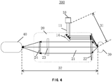
- FIG. 4 shows a structural diagram of a Raman spectrum inspection apparatus according to another embodiment of the disclosure.
- the optical device 20 also includes a first lens 22 and a filter 23.
- the first lens 22 may be configured to collect the optical signal 21 from the position, which is irradiated by the exciting light 11, of the sample 30 to be inspected.
- the exciting light 11 passes through the first lens 22 and is focused by the first lens 22 onto the sample 30 to be inspected, while the exciting light 11 and the optical signal 21 which is directed to the spectrometer 40 from the excitation position of the sample 30 to be inspected are separated from each other, e.g., in space.
- a first lens 22 having a relatively large diameter may be selected to be sufficient to collect the optical signal 21 on a region of the lens while converging the exciting light 11 on another region. Such two regions are separated from each other.
- the exciting light 11 since a beam diameter of the exciting light 11 is usually smaller than a beam diameter of the optical signal 21 from the excitation position, the exciting light 11 can be guided onto the region of the first lens 22 near its periphery, while leaving a large region to collect the optical signal 21.
- the diameter of the first lens 22 may be arranged to be greater than sum of the beam diameter of the exciting light 11 and the beam diameter of the optical signal 21 received by the spectrometer 40 from the excitation position. In this way, the excitation optical path and the detection optical path both pass through the first lens 22 without intersecting each other.
- the lens for converging the exciting light 11 and the lens for collecting the optical signal 21 is the same lens, thus the excitation position of the exciting light 11 on the sample 30 to be inspected can be easily adjusted to a focal point of the first lens 22.
- Collecting the optical signal 21 from the focal point of the first lens 22 helps to increase the collection efficiency, which can significantly increase the intensity of the collected optical signal 21.
- the first lens 22 can collimate the optical signal 21 from the excitation position at its focal point into approximately parallel light beams, which also facilitates the transmission of the optical signal 21.
- a mirror 14 may be provided in the excitation optical path.
- the mirror 14 is configured to guide the exciting light 11 to the first lens 22.
- the first lens 22 may be an aspheric lens, which helps to avoid distortion of the optical path, especially for the first lens 22 with a large diameter. Since different regions of the first lens 22 are respectively used for converging the exciting light 11 and collecting the optical signal 21, it is also very advantageous to prevent the distortion of the optical paths.
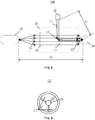
- FIG. 5 shows a structural diagram of a Raman spectrum inspection apparatus according to still another embodiment of the disclosure.
- the optical device 20 also includes the first lens 22 and the filter 23.
- the first lens 22 may be configured to collect the optical signal 21 from a position, which is irradiated by the exciting light 11, of the sample 30 to be inspected.
- the exciting light 11 passes through the first lens 22 and is focused by the first lens 22 onto the sample 30 to be inspected.
- the exciting light 11 and a part of the optical signal 21 from an excitation position of the sample 30 to be inspected are separated from each other.
- the exciting light 11 is separated from only a part (but not all) of the optical signal 21, while another part of the optical signal 21 not separated from the exciting light 11 may be unable to reach the spectrometer. This means that a part of the optical signal 21 from the excitation position can be appropriately sacrificed to avoid the use of a dichroic mirror.
- the lens for converging the exciting light 11 and the lens for collecting the optical signal 21 is the same lens. Therefore, the excitation position of the exciting light 11 on the sample 30 to be inspected can be easily adjusted to a focal point of the first lens 22. Collecting the optical signal 21 from the focal point of the first lens 22 helps to increase the collection efficiency, which can also significantly increase the intensity of the collected optical signal 21, and which can also collimate the optical signal 21 from the excitation position at the focal point into approximately parallel light beams. Furthermore, since the exciting light 11 is not necessary to be separated from all of parts of the optical signal 21 having passed through the first lens 22, this can make the spatial arrangement more compact.
- a reflective component 15 may be provided in the excitation optical path.
- the reflective component 15 may be provided between the first lens 22 and the filter 23, and configured to guide the exciting light 11 to the first lens 22 and to only partially block the optical signal 21 from the excitation position of the sample 30 to be inspected.
- the reflective component 15 is provided not only in the optical path of the exciting light 11, but also in the optical path of the optical device 20.
- the optical path 31 in which the exciting light 11 passes from the exciting light source 10 to the sample 30 to be inspected and the optical path 32 in which the optical signal 21 received by the spectrometer 40 passes from the sample 30 to be inspected to the spectrometer 40 are still separated from each other, because the part of the optical signal 21 that is not separated from the exciting light 11 is blocked by the reflective component 15 rather than received by the spectrometer 40.
- the optical path 32 in which the part of the optical signal 21 received by the spectrometer 40 passes from the sample 30 to be inspected to the spectroscope 40 is still separated from the excitation optical path. In the example of FIG.
- the reflective component 15 blocks a middle part of the optical signal 21 collected by the first lens 22, and the blocked part of the optical signal will not reach the spectrometer 40. However, the part of optical signal surrounding the reflective component 15 is not blocked by the reflective component 15, and can still be directed to the spectrometer 40. The optical path in which the optical signal that finally reaches the spectrometer 40 is still separated from the excitation optical path.
- a projection area of a reflective surface of the reflective component 15 on the first lens 22 may be smaller than an area of the first lens 22, and may be, for example, 50%, 30%, 10%, or less of the area of the first lens 22, such as 20% to 40% of the area of the first lens 22. This may ensure that the reflective component 15 does not block all of parts of the optical signal 21 collected by the first lens 22.
- reduction of the projection area of the reflective surface of the reflective component 15 on the first lens 22 facilitates increasing the intensity of the optical signal reaching the spectrometer 40.
- the diameter of the reflective component 15 cannot be too small to provide sufficient exciting light 11 reflected to the sample 30 for the Raman inspection.
- the reflective component 15 can guide the exciting light 11 toward the first lens 22 along an axis of the first lens 22.
- the portion of the reflective component 15 for reflecting the exciting light 11 is for example located on the axis of the first lens 22.
- the embodiments of the present disclosure are not limited to this.
- the reflective component 15 may be a physical mirror, as shown in FIG. 5 . Alternatively, it may have other forms as well.
- the reflective component 15 may have: a reflective region 16 for reflecting the exciting light 11; and a light transmission hole 17 allowing a part of the optical signal 21 from the excitation position of the sample 30 to be inspected to pass through.
- the reflective region 16 may be located in a central portion of the reflective component 15, while the light transmission hole 17 may be located radially outside the reflective region 16. In this circumstance, the area of the reflective region 16 may also meet the above mentioned ratio.
- the overall shape of the reflective component 15 may be any shape such as a circle, a rectangle, a square, a hexagon, etc.
- the optical device 20 may further include a third lens 24 configured to focus and deliver the optical signal 21, which has passed through the filter 23, to the spectrometer 40.
- the third lens 24 helps to increase the efficiency of the spectroscope 40 for receiving the optical signal.
- the filter 23 may be a long-pass filter or a notch filter. It can effectively filter out Rayleigh scattering light.
- the optical signal 21 collected by the first lens 22 often includes not only the Raman optical signal 21, but also Rayleigh light, fluorescence, etc.
- the exciting light has a shorter wavelength than Raman light, and thus can be removed using a long-pass filter or notch filter.
- a cut-off wavelength of the long-pass filter or the notch filter can be set according to actual requirements. For example, when the Raman spectrum processed by the spectrometer in the Raman spectrum inspection apparatus has a wavelength range of 550 to 1100 nm, the cut-off wavelength can be set to allow light in the wavelength range to pass through.
- the spectrum data obtained by the Raman spectrum inspection apparatus can further be subject to processes of random noise removal and baseline correction so as to reduce the influence of noise.
- Random noise removal removes the random noise contained in the spectrum.
- Common methods include, but are not limited to: moving window average smoothing, polynomial moving average filtering, and the like.
- Baseline correction is used to remove the fluorescence signal in the signal light, thereby obtaining a relatively pure Raman signal.
- Common methods include, but are not limited to: polynomial fitting, wavelet transform techniques, Fourier transform techniques, and the like. The processing of signals is not limited to the above two ways.
- the Raman spectrum inspection apparatus with the separation design of the excitation optical path and the detection optical path, it avoids the use of a dichroic mirror, suppresses the noise peak envelope caused by the dichroic mirror, and improves the inspection accuracy of the Raman signal, especially improves the ability to resist the interference of fluorescence.
Landscapes
- Physics & Mathematics (AREA)
- Spectroscopy & Molecular Physics (AREA)
- General Physics & Mathematics (AREA)
- Health & Medical Sciences (AREA)
- Nuclear Medicine, Radiotherapy & Molecular Imaging (AREA)
- Life Sciences & Earth Sciences (AREA)
- Chemical & Material Sciences (AREA)
- Analytical Chemistry (AREA)
- Biochemistry (AREA)
- General Health & Medical Sciences (AREA)
- Immunology (AREA)
- Pathology (AREA)
- Investigating, Analyzing Materials By Fluorescence Or Luminescence (AREA)
Abstract
Description
- Embodiments of the disclosure relate to the technical field of Raman spectrum inspection, and in particular to a Raman spectrum inspection apparatus.
- Raman spectrum analysis technology is a non-contact spectrum analysis technology based on Raman scattering effect, which can qualitatively and quantitatively analyse the composition of a substance. Raman spectrum is a molecular vibration spectrum that can reflect the fingerprint characteristics of molecules, and can be used for the inspection of substance. Since the difference between a wave number of Raman spectrum and a wave number of the incident light is independent of a light source, but is determined only by the scattering object (i.e., object to be inspected), the Raman spectrometer can inspect and identify the substance by the Raman spectrum generated by the Raman effect of the object to be inspected for an exciting light. Raman spectrum inspection methods have been widely used in the fields of liquid security inspection, gem identification, explosive inspection, drug inspection, medicine inspection, etc.
- In recent years, Raman spectrum analysis technology has been widely used in the fields of dangerous goods inspection and substance identification. In the field of substance identification, because the colours and shapes of various substances are different from each other, it is usually hard for a person to accurately determine the properties of the substance, and a Raman spectrum is determined by the molecular energy level structure of the object to be inspected, and thus a Raman spectrum can be used as the "fingerprint" information of a substance for substance identification. Therefore, Raman spectrum analysis technology has been widely used in the fields of customs, public safety, food & medicine, environment, etc.
- In prior Raman spectrum inspection apparatus, an optical path for the exciting light and an detection opticalpath are often coincident. In order to make the exciting light that is reflected or scattered by the object to be inspected not affect the inspection of the Raman spectrum (signal light), dichroic mirrors are often used for beam-splitting. The dichroic mirror exhibits high reflectivity to the exciting light, while exhibiting high transmissivity to the Raman scattering signal light. However, in practice, the conventional Raman spectrum inspection apparatus having the dichroic mirror is not satisfied for detection of weak Raman signal.
- In order to alleviate the above issues of the conventional Raman inspection apparatus in the prior art, an embodiment of the disclosure provides a new Raman spectrum inspection apparatus.
- An embodiment provides a Raman spectrum inspection apparatus, including:
- an exciting light source configured to emit an exciting light to a sample to be inspected;
- an optical device configured to collect an optical signal from a position, which is irradiated by the exciting light, of the sample to be inspected; and
- a spectrometer configured to generate a Raman spectrum of the sample to be inspected from a received optical signal,
- wherein an excitation optical path in which the exciting light passes from the exciting light source to the sample to be inspected and a detection optical path in which the optical signal received by the spectrometer passes from the sample to be inspected to the spectrometer are separated from each other.
- In an embodiment, the excitation optical path in which the exciting light passes from the exciting light source to the sample to be inspected offsets by a predetermined angle relative to the detection optical path in which the optical signal received by the spectrometer passes from the sample to be inspected to the spectrometer.
- In an embodiment, the predetermined angle is between 15 degrees and 90 degrees.
- In an embodiment, the predetermined angle is between 20 degrees and 60 degrees.
- In an embodiment, the optical device includes:
- a first lens configured to collect the optical signal from the position, which is irradiated by the exciting light, of the sample to be inspected; and
- a filter configured to filter out the exciting light from the optical signal having passed through the first lens.
- In an embodiment, the predetermined angle is set such that the exciting light is kept away from the first lens.
- In an embodiment, a second lens is provided in the excitation optical path in which the exciting light passes from the exciting light source to the sample to be inspected, and the second lens is configured to focus the exciting light on the sample to be inspected.
- In an embodiment, the optical device includes:
- a first lens configured to collect the optical signal from the position, which is irradiated by the exciting light, of the sample to be inspected; and
- a filter configured to filter out the exciting light from the optical signal having passed through the first lens,
- wherein the exciting light passes through the first lens and is focused by the first lens to the sample to be inspected.
- In an embodiment, a mirror is set in the excitation optical path, and the mirror is configured to guide the exciting light to the first lens.
- In an embodiment, the first lens is an aspheric lens.
- In an embodiment, a diameter of the first lens is greater than sum of a beam diameter of the exciting light and a beam diameter of the optical signal delivered to the spectrometer from an excitation position.
- In an embodiment, the optical device includes:
- a first lens configured to collect the optical signal from the position, which is irradiated by the exciting light, of the sample to be inspected; and
- a filter configured to filter out the exciting light from the optical signal having passed the first lens;
- wherein the exciting light passes through the first lens and is focused by the first lens to the sample to be inspected; and the exciting light and a part of the optical signal from the position, which is irradiated by the exciting light, of the sample to be inspected are separated from each other.
- In an embodiment, a reflective component is provided in the excitation optical path, and the reflective component is provided between the first lens and the filter, and is configured to guide the exciting light to the first lens and only partially block the optical signal from the position, which is irradiated by the exciting light, of the sample to be inspected.
- In an embodiment, a projection area of a reflective surface of the reflective component on the first lens is smaller than area of the first lens.
- In an embodiment, the reflective component has a reflective region for reflecting the exciting light, and a light transmission hole allowing a part of the optical signal from the position, which is irradiated by the exciting light, of the sample to be inspected to pass through.
- In an embodiment, the optical device further includes:
a third lens configured to focus and transmit the optical signal having passed through the filter to the spectrometer. - In an embodiment, the filter is a long-pass filter or a notch filter.
- With the Raman spectrum inspection apparatus according to the above embodiments, it is possible to avoid using a dichroic mirror, thereby improving the inspection accuracy of the Raman spectrum inspection apparatus on the Raman signal.
- For a better understanding of the disclosure, embodiments of the disclosure will be described according to the following figures:
-
FIG. 1 shows a structural diagram of a conventional Raman spectrum inspection apparatus having a dichroic mirror; -
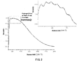
FIG. 2 shows a schematic diagram of a Raman spectrum having noise peak envelope obtained using the Raman spectrum inspection apparatus as shown inFIG. 1 ; -
FIG. 3 shows a structural diagram of a Raman spectrum inspection apparatus according to an embodiment of the disclosure; -
FIG. 4 shows a structural diagram of a Raman spectrum inspection apparatus according to another embodiment of the disclosure; -
FIG. 5 shows a structural diagram of a Raman spectrum inspection apparatus according to still another embodiment of the disclosure; -
FIG. 6 shows a reflective component in a Raman spectrum inspection apparatus according to an embodiment of the disclosure; -
FIG. 7A andFIG. 7B show an inhibitory effect of the Raman spectrum inspection apparatus according to embodiments of the disclosure on noise peak envelope by comparison; and -
FIG. 8A and FIG. 8B in enlarged view show an inhibitory effect of the Raman spectrum inspection apparatus according to embodiments of the disclosure on noise peak envelope by comparison. - The figures do not show all of the circuits or structures in the Raman spectrum inspection apparatus according to embodiments of the disclosure. The same reference numerals denote the same or similar components or features throughout the drawings.
- Technical solution of the disclosure will be further described in detail by way of embodiments with reference to the accompanying drawings. In the description, the same or similar reference numerals denote the same or similar components. The following description of embodiments of the disclosure with reference to the drawings is intended to explain the general inventive concept of the disclosure, and should not be construed as a limitation of the disclosure.
- According to the general concept of the disclosure, it provides a Raman spectrum inspection apparatus including: an exciting light source configured to emit an exciting light to a sample to be inspected; an optical device configured to collect an optical signal from a position, which is irradiated by the exciting light, of the sample to be inspected; and a spectrometer configured to generate a Raman spectrum of the sample to be inspected from the received optical signal, wherein an optical path in which the exciting light passes from the exciting light source to the sample to be inspected (called as an excitation optical path) and an optical path in which the optical signal received by the spectrometer passes from the sample to be inspected to the spectrspectrometerometer (called as a detection optical path) are separated from each other. As an example, the excitation optical path is adjacent to the detection optical path.
- Additionally, in the following detailed description, for ease of explanation, many specific details are set forth in order to provide a thorough understanding of the disclosed embodiments. However, it will be apparent that one or more embodiments may also be practiced without these specific details. In other instances, well-known structures and devices are shown in the drawings to simplify the drawings.
-
FIG. 1 shows a structural diagram of a conventional Ramanspectrum inspection apparatus 100. Adichroic mirror 12 is provided in the Ramanspectrum inspection apparatus 100. Thedichroic mirror 12 exhibits high reflectivity for anexciting light 11, while exhibiting high transmissivity for a Raman scattering signal light 21'. Thedichroic mirror 12 is inclined with respect to both the excitation optical path and the detection optical path. Thus, theexciting light 11 may be reflected by thedichroic mirror 12 to asample 30 to be inspected, and the Raman scattering signal light 21' from thesample 30 to be inspected may be directed through thedichroic mirror 12 toward aspectrometer 40. - Since the sample to be inspected is excited by the exciting light, not only the Raman scattering light will be emitted, but also fluorescence will be excited out. Therefore, in order to obtain a pure Raman signal, it needs to subtract a fluorescence signal from the obtained signal through a process such as baseline correction at the final spectrometer. However, when the fluorescence of the sample is strong, there will be a "noise peak envelope", that is, there is a relatively large amplitude of spike noise in the Raman spectral signal, as shown in
FIG. 2 (the intensity of the vertical ordinate inFIG. 2 indicates normalized values). However, these noise peak envelopes cannot be removed by baseline correction. Therefore, the Raman scattering optical signal is likely to be impure. Finally, the measured signal will include these spike noises of the fluorescence, which will result in erroneous substance inspection. After long-term studies by the inventors of the present application, it has been found that the occurrence of these noise peak envelopes is greatly associated with the dichroic mirror in the Raman spectrum inspection apparatus. For this reason, in the embodiments of the disclosure, a Raman spectrum inspection apparatus that does not include a dichroic mirror is provided. -
FIG. 3 shows a Ramanspectrum inspection apparatus 200 according to an embodiment of the disclosure. The Ramanspectrum inspection apparatus 200 includes: an exciting light source (for example a laser device) 10 configured to emit theexciting light 11 to thesample 30 to be inspected; anoptical device 20 configured to collect anoptical signal 21 from a position, which is irradiated by theexciting light 11, of thesample 30 to be inspected; and aspectrometer 40 configured to generate a Raman spectrum of thesample 30 to be inspected from the received optical signal. In this embodiment, anoptical path 31 in which the exciting light 11 passes from the excitinglight device 20 to thesample 30 to be inspected and anoptical path 32 passed through by theoptical signal 21 received by thespectrometer 40 from thesample 30 to be inspected to thespectrometer 40 are separated from each other. In this embodiment, since theoptical path 31 of theexciting light 11 is separated from theoptical path 32 of theoptical signal 21, thedichroic mirror 12 in the Ramanspectrum inspection apparatus 200 can be omitted. - With the above-mentioned Raman
spectrum inspection apparatus 200 that does not include a dichroic mirror, the spike noise of the fluorescence in the Raman spectral signal described above can be effectively suppressed.FIG. 7A shows the noise peak envelope in the Raman spectral signal obtained by a Raman spectrum inspection apparatus using adichroic mirror 12.FIG. 7B shows the effect of the above-mentioned Raman spectrum inspection apparatus according to the embodiments of the present disclosure suppressing the noise peak envelope. From the comparison ofFIG. 7A andFIG. 7B , it can be seen that the Ramanspectrum inspection apparatus 200 according to the embodiments of the present disclosure can significantly suppress the noise peak envelope. In order to show the effect of suppressing the noise peak envelope more clearly,FIG. 8A and FIG. 8B are provided.FIG. 8A shows a locally enlarged view of the spectral signal obtained by the Raman spectrum inspection apparatus having thedichroic mirror 12.FIG. 8B shows a locally enlarged view of the spectral signal obtained by the above Ramanspectrum inspection apparatus 200 that does not include the dichroic mirror. The signals shown inFIG. 8A and FIG. 8B are those that have been processed by such as baseline correction and removal of random noises. Such two data processing methods will be explained at the last paragraphs of the present description. FromFIG. 8A , it can be seen that spike noises with large amplitudes may be observed in the left part inFIG. 8A after the baseline correction (removing the baseline) has been applied to the signal. The inventors have found these are noise interference caused by the dichroic mirror. If Raman characteristic peaks in the detection signal are relatively weak, the amplitudes of the characteristic peaks may be comparable to those of the spike pulses shown in the left part inFIG. 8A or even less than those of the spike pulses shown in the left part inFIG. 8A , and thus errors will occur in inspection. In contrast, from the spectrum signal after the baseline correction (removing the baseline)FIG. 8B , it can be seen that the Ramanspectrum inspection apparatus 200 that does not include the dichroic mirror can effectively suppress the spike noises of fluorescence (i.e., "noise peak envelope"), for example, a noise variance of the Raman spectral signal can be reduced to a low value of about 0.2. - As described above, the use of a Raman
spectrum inspection apparatus 200 that does not include a dichroic mirror may significantly reduce the noise peak envelope, which is significant for Raman inspection of weak signals. When the sample to be inspected has strong fluorescence signal and weak Raman signal, if a Raman spectrum inspection apparatus including a dichroic mirror is used for inspection, the Raman optical signal is likely to be submerged in the noise peak envelope and treated as noise. In contrast, after eliminating an influence of the dichroic mirror, the probability of Raman signal to be extracted will increase greatly, thereby improving the ability of detecting weak Raman signal with fluorescence interference. - As an example, as shown in
FIG. 3 , in the Ramanspectrum inspection apparatus 200, the optical path 31 (hereinafter referred to as an excitation optical path) in which theexciting light 11 travels from the excitinglight source 10 to asample 30 to be inspected offsets by a predetermined angle relative to the optical path 32 (hereinafter referred to as a detection optical path) in whichoptical signal 21 received by thespectrometer 40 travels from thesample 30 to be inspected to thespectrometer 40. In this way, the excitation optical path and the detection opticalpath can be separated from each other, and the irradiation position (or referred to as excitation position) of theexciting light 11 on thesample 30 to be inspected can be kept substantially the same as the position of theoptical signal 21 collected by theoptical device 20, thereby avoiding using a dichroic mirror. - Regarding the predetermined angle by which the excitation optical path offsets with respect to the detection optical path, the inventors have developed it thoroughly. On one hand, in order to make the area on which the exciting light is focused in coincidence with the focusing area of the
first lens 22 for collecting the signal light as possible, the predetermined angle is as small as possible while separating the two optical paths (the excitation optical path and the detection optical path) from each other and preventing their mounts from being interfered with each other; on the other hand, thefirst lens 22 for collecting the signal light should have an enough large diameter to collect sufficient signal light, however, the predetermined angle between the detection optical path and the excitation optical path will increase as the diameter of thefirst lens 22 increases. Thus, a balance between the above two aspects is desired. In an embodiment, the predetermined angle may be between 15 degrees and 90 degrees, such as between 20 degrees and 60 degrees. The predetermined angle can prevent the excitation optical path and the detection optical path from being disturbed by each other. - In an embodiment, the
optical device 200 may include afirst lens 22 and afilter 23. Thefirst lens 22 may be configured to collect theoptical signal 21 from a position (hereinafter referred to as excitation position), which is irradiated by theexciting light 11, of thesample 30 to be inspected. As an example, thefirst lens 22 can collimate theoptical signal 21 to some extent. Thefilter 23 may be configured to filter out the exciting light from the optical signal passed through thefirst lens 22. Thefilter 23 can fully realize the long-pass filtering function of a dichroic mirror, and can avoid the noise peak envelope caused by the dichroic mirror. - As an example, a
second lens 13 may be provided in the excitation optical path, and thesecond lens 13 is configured to focus theexciting light 11 onto thesample 30 to be inspected. However, thesecond lens 13 is not always necessary, for example, theexciting light 11 may also directly illuminate thesample 30 to be inspected without being focused by the lens. - As an example, the
optical device 20 may further include athird lens 24. Thethird lens 24 is configured to focus theoptical signal 21 having passed through afilter 23 and to direct it to thespectrometer 40. Thethird lens 24 may help to increase the efficiency of thespectrometer 40 receiving the optical signal. -
FIG. 4 shows a structural diagram of a Raman spectrum inspection apparatus according to another embodiment of the disclosure. - In another example, in the Raman
spectrum inspection apparatus 300 shown inFIG. 4 , theoptical device 20 also includes afirst lens 22 and afilter 23. Thefirst lens 22 may be configured to collect theoptical signal 21 from the position, which is irradiated by theexciting light 11, of thesample 30 to be inspected. The exciting light 11 passes through thefirst lens 22 and is focused by thefirst lens 22 onto thesample 30 to be inspected, while theexciting light 11 and theoptical signal 21 which is directed to thespectrometer 40 from the excitation position of thesample 30 to be inspected are separated from each other, e.g., in space. In this example, it is also possible to avoid using the dichroic mirror. For example, afirst lens 22 having a relatively large diameter may be selected to be sufficient to collect theoptical signal 21 on a region of the lens while converging theexciting light 11 on another region. Such two regions are separated from each other. As an example, since a beam diameter of theexciting light 11 is usually smaller than a beam diameter of theoptical signal 21 from the excitation position, theexciting light 11 can be guided onto the region of thefirst lens 22 near its periphery, while leaving a large region to collect theoptical signal 21. As an example, the diameter of thefirst lens 22 may be arranged to be greater than sum of the beam diameter of theexciting light 11 and the beam diameter of theoptical signal 21 received by thespectrometer 40 from the excitation position. In this way, the excitation optical path and the detection optical path both pass through thefirst lens 22 without intersecting each other. - In the above example, the lens for converging the
exciting light 11 and the lens for collecting theoptical signal 21 is the same lens, thus the excitation position of theexciting light 11 on thesample 30 to be inspected can be easily adjusted to a focal point of thefirst lens 22. Collecting theoptical signal 21 from the focal point of thefirst lens 22 helps to increase the collection efficiency, which can significantly increase the intensity of the collectedoptical signal 21. Thefirst lens 22 can collimate theoptical signal 21 from the excitation position at its focal point into approximately parallel light beams, which also facilitates the transmission of theoptical signal 21. - In an example, in order to guide the exciting light directionally to a suitable region of the
first lens 22, amirror 14 may be provided in the excitation optical path. Themirror 14 is configured to guide theexciting light 11 to thefirst lens 22. - As an example, the
first lens 22 may be an aspheric lens, which helps to avoid distortion of the optical path, especially for thefirst lens 22 with a large diameter. Since different regions of thefirst lens 22 are respectively used for converging theexciting light 11 and collecting theoptical signal 21, it is also very advantageous to prevent the distortion of the optical paths. -
FIG. 5 shows a structural diagram of a Raman spectrum inspection apparatus according to still another embodiment of the disclosure. - In another example, in the Raman
spectrum inspection apparatus 400 shown inFIG. 5 , theoptical device 20 also includes thefirst lens 22 and thefilter 23. Thefirst lens 22 may be configured to collect theoptical signal 21 from a position, which is irradiated by theexciting light 11, of thesample 30 to be inspected. The exciting light 11 passes through thefirst lens 22 and is focused by thefirst lens 22 onto thesample 30 to be inspected. And theexciting light 11 and a part of theoptical signal 21 from an excitation position of thesample 30 to be inspected are separated from each other. In this example, theexciting light 11 is separated from only a part (but not all) of theoptical signal 21, while another part of theoptical signal 21 not separated from theexciting light 11 may be unable to reach the spectrometer. This means that a part of theoptical signal 21 from the excitation position can be appropriately sacrificed to avoid the use of a dichroic mirror. - In this example, the lens for converging the
exciting light 11 and the lens for collecting theoptical signal 21 is the same lens. Therefore, the excitation position of theexciting light 11 on thesample 30 to be inspected can be easily adjusted to a focal point of thefirst lens 22. Collecting theoptical signal 21 from the focal point of thefirst lens 22 helps to increase the collection efficiency, which can also significantly increase the intensity of the collectedoptical signal 21, and which can also collimate theoptical signal 21 from the excitation position at the focal point into approximately parallel light beams. Furthermore, since theexciting light 11 is not necessary to be separated from all of parts of theoptical signal 21 having passed through thefirst lens 22, this can make the spatial arrangement more compact. - As an example, a
reflective component 15 may be provided in the excitation optical path. Thereflective component 15 may be provided between thefirst lens 22 and thefilter 23, and configured to guide theexciting light 11 to thefirst lens 22 and to only partially block theoptical signal 21 from the excitation position of thesample 30 to be inspected. In this example, thereflective component 15 is provided not only in the optical path of theexciting light 11, but also in the optical path of theoptical device 20. However, theoptical path 31 in which the exciting light 11 passes from the excitinglight source 10 to thesample 30 to be inspected and theoptical path 32 in which theoptical signal 21 received by thespectrometer 40 passes from thesample 30 to be inspected to thespectrometer 40 are still separated from each other, because the part of theoptical signal 21 that is not separated from theexciting light 11 is blocked by thereflective component 15 rather than received by thespectrometer 40. Theoptical path 32 in which the part of theoptical signal 21 received by thespectrometer 40 passes from thesample 30 to be inspected to thespectroscope 40 is still separated from the excitation optical path. In the example ofFIG. 5 , thereflective component 15 blocks a middle part of theoptical signal 21 collected by thefirst lens 22, and the blocked part of the optical signal will not reach thespectrometer 40. However, the part of optical signal surrounding thereflective component 15 is not blocked by thereflective component 15, and can still be directed to thespectrometer 40. The optical path in which the optical signal that finally reaches thespectrometer 40 is still separated from the excitation optical path. - As an example, a projection area of a reflective surface of the
reflective component 15 on thefirst lens 22 may be smaller than an area of thefirst lens 22, and may be, for example, 50%, 30%, 10%, or less of the area of thefirst lens 22, such as 20% to 40% of the area of thefirst lens 22. This may ensure that thereflective component 15 does not block all of parts of theoptical signal 21 collected by thefirst lens 22. In general, reduction of the projection area of the reflective surface of thereflective component 15 on thefirst lens 22 facilitates increasing the intensity of the optical signal reaching thespectrometer 40. However, the diameter of thereflective component 15 cannot be too small to provide sufficientexciting light 11 reflected to thesample 30 for the Raman inspection. As an example, thereflective component 15 can guide theexciting light 11 toward thefirst lens 22 along an axis of thefirst lens 22. The portion of thereflective component 15 for reflecting theexciting light 11 is for example located on the axis of thefirst lens 22. However, the embodiments of the present disclosure are not limited to this. - In an example, the
reflective component 15 may be a physical mirror, as shown inFIG. 5 . Alternatively, it may have other forms as well. For example, as shown inFIG. 6 , thereflective component 15 may have: areflective region 16 for reflecting theexciting light 11; and alight transmission hole 17 allowing a part of theoptical signal 21 from the excitation position of thesample 30 to be inspected to pass through. As an example, thereflective region 16 may be located in a central portion of thereflective component 15, while thelight transmission hole 17 may be located radially outside thereflective region 16. In this circumstance, the area of thereflective region 16 may also meet the above mentioned ratio. Such structure is more conducive to adjusting and fixing thereflective component 15. The overall shape of thereflective component 15 may be any shape such as a circle, a rectangle, a square, a hexagon, etc. - As an example, the
optical device 20 may further include athird lens 24 configured to focus and deliver theoptical signal 21, which has passed through thefilter 23, to thespectrometer 40. Thethird lens 24 helps to increase the efficiency of thespectroscope 40 for receiving the optical signal. - As an example, the
filter 23 may be a long-pass filter or a notch filter. It can effectively filter out Rayleigh scattering light. Theoptical signal 21 collected by thefirst lens 22 often includes not only the Ramanoptical signal 21, but also Rayleigh light, fluorescence, etc. The exciting light has a shorter wavelength than Raman light, and thus can be removed using a long-pass filter or notch filter. A cut-off wavelength of the long-pass filter or the notch filter can be set according to actual requirements. For example, when the Raman spectrum processed by the spectrometer in the Raman spectrum inspection apparatus has a wavelength range of 550 to 1100 nm, the cut-off wavelength can be set to allow light in the wavelength range to pass through. - Additionally, in order to remove the interference in the
optical signal 21, the spectrum data obtained by the Raman spectrum inspection apparatus can further be subject to processes of random noise removal and baseline correction so as to reduce the influence of noise. Random noise removal removes the random noise contained in the spectrum. Common methods include, but are not limited to: moving window average smoothing, polynomial moving average filtering, and the like. Additionally, before the analysis of the spectrum, it is possible to inhibit the fluorescence background to some extent. Baseline correction is used to remove the fluorescence signal in the signal light, thereby obtaining a relatively pure Raman signal. Common methods include, but are not limited to: polynomial fitting, wavelet transform techniques, Fourier transform techniques, and the like. The processing of signals is not limited to the above two ways. - According to the Raman spectrum inspection apparatus of embodiments of the disclosure, with the separation design of the excitation optical path and the detection optical path, it avoids the use of a dichroic mirror, suppresses the noise peak envelope caused by the dichroic mirror, and improves the inspection accuracy of the Raman signal, especially improves the ability to resist the interference of fluorescence.
- Unless there are technical obstacles or contradictions, the above various embodiments of the disclosure can be freely combined to form additional embodiments. These other embodiments all fall within the protection scope of the disclosure.
- Although the disclosure has been described in conjunction with the drawings, the embodiments disclosed in the drawings are intended to illustrate the exemplified embodiments of the disclosure and cannot be construed as a limitation of the disclosure. The dimensional proportions in the drawings are merely schematic, and are not to be construed as limiting the disclosure.
Claims (15)
- A Raman spectrum inspection apparatus (200), comprising:an exciting light source (10) configured to emit an exciting light to a sample (30) to be inspected;an optical device (20) configured to collect an optical signal (21) from a position, which is irradiated by the exciting light (11), of the sample (30) to be inspected; anda spectrometer (40) configured to generate a Raman spectrum of the sample (30) to be inspected from a received optical signal (21),wherein an excitation optical path (31) in which the exciting light (11) passes from the exciting light source (10) to the sample (30) to be inspected and a detection optical path (32) in which the optical signal received by the spectrometer (40) passes from the sample (30) to be inspected to the spectrometer (40) are separated from each other.
- The Raman spectrum inspection apparatus (200) of claim 1, wherein the excitation optical path in which the exciting light (11) passes from the exciting light source (10) to the sample (30) to be inspected offsets by a predetermined angle relative to the detection optical path (32) in which the optical signal (21) received by the spectrometer (40) passes from the sample (30) to be inspected to the spectrometer (40).
- The Raman spectrum inspection apparatus (200) of claim 2, wherein the predetermined angle is between 15 degrees and 90 degrees.
- The Raman spectrum inspection apparatus (200) of claim 2, wherein the predetermined angle is between 20 degrees and 60 degrees.
- The Raman spectrum inspection apparatus (200) of claim 2, wherein the optical device (20) comprises:a first lens (22) configured to collect the optical signal (21) from the position, which is irradiated by the exciting light (11), of the sample (30) to be inspected; anda filter (23) configured to filter out the exciting light (11) from the optical signal (21) having passed through the first lens (22).
- The Raman spectrum inspection apparatus (200) of claim 5, wherein the predetermined angle is set such that the exciting light (11) is kept away from the first lens (22).
- The Raman spectrum inspection apparatus (200) of claim 2, wherein a second lens (13) is provided in the excitation optical path (31) in which the exciting light (11) passes from the exciting light source (10) to the sample (30) to be inspected, and the second lens (13) is configured to focus the exciting light (11) on the sample (30) to be inspected.
- The Raman spectrum inspection apparatus (200) of claim 1, wherein the optical device (20) comprises:a first lens (22) configured to collect the optical signal (21) from the position, which is irradiated by the exciting light (11), of the sample (30) to be inspected; anda filter (23) configured to filter out the exciting light (11) from the optical signal (21) having passed through the first lens (22),wherein the exciting light (11) passes through the first lens (22) and is focused by the first lens (22) to the sample (30) to be inspected.
- The Raman spectrum inspection apparatus (200) of claim 8, wherein a mirror (14) is set in the excitation optical path (31), and the mirror (14) is configured to guide the exciting light (11) to the first lens (22).
- The Raman spectrum inspection apparatus (200) of claim 8, wherein the first lens (22) is an aspheric lens.
- The Raman spectrum inspection apparatus (200) of claim 8, wherein a diameter of the first lens (22) is greater than sum of a beam diameter of the exciting light (11) and a beam diameter of the optical signal (21) delivered to the spectrometer (40) from an excitation position.
- The Raman spectrum inspection apparatus (200) of claim 1, wherein the optical device (20) comprises:a first lens (22) configured to collect the optical signal (21) from the position, which is irradiated by the exciting light (11), of the sample (30) to be inspected; anda filter (23) configured to filter out the exciting light (11) from the optical signal (21) having passed through the first lens (22);wherein the exciting light (11) passes through the first lens (22) and is focused by the first lens (22) to the sample (30) to be inspected; and the exciting light (11) and a part of the optical signal (21) from the position, which is irradiated by the exciting light (11), of the sample (30) to be inspected are separated from each other.
- The Raman spectrum inspection apparatus (200) of claim 12, wherein a reflective component (15) is provided in the excitation optical path (31), and the reflective component (15) is provided between the first lens (22) and the filter (23), and is configured to guide the exciting light (11) to the first lens (22) and only partially block the optical signal (21) from the position, which is irradiated by the exciting light (11), of the sample (30) to be inspected.
- The Raman spectrum inspection apparatus (200) of claim 13, wherein a projection area of a reflective surface of the reflective component (15) on the first lens (22) is smaller than area of the first lens (22).
- The Raman spectrum inspection apparatus (200) of claim 13, wherein the reflective component (15) has a reflective region (16) for reflecting the exciting light (11), and a light transmission hole (17) allowing a part of the optical signal (21) from the position, which is irradiated by the exciting light (11), of the sample (30) to be inspected to pass through.
Applications Claiming Priority (1)
| Application Number | Priority Date | Filing Date | Title |
|---|---|---|---|
| CN201710616652.1A CN107328755B (en) | 2017-07-25 | 2017-07-25 | Raman spectrum detection equipment |
Publications (2)
| Publication Number | Publication Date |
|---|---|
| EP3435072A1 true EP3435072A1 (en) | 2019-01-30 |
| EP3435072B1 EP3435072B1 (en) | 2020-09-16 |
Family
ID=60227422
Family Applications (1)
| Application Number | Title | Priority Date | Filing Date |
|---|---|---|---|
| EP18185563.6A Active EP3435072B1 (en) | 2017-07-25 | 2018-07-25 | Raman spectrum inspection apparatus |
Country Status (3)
| Country | Link |
|---|---|
| US (1) | US10670457B2 (en) |
| EP (1) | EP3435072B1 (en) |
| CN (1) | CN107328755B (en) |
Cited By (2)
| Publication number | Priority date | Publication date | Assignee | Title |
|---|---|---|---|---|
| EP4137800A1 (en) * | 2021-08-16 | 2023-02-22 | Endress+Hauser Optical Analysis, Inc. | Spatially offset raman probe with coaxial excitation and collection apertures |
| US20240402009A1 (en) * | 2021-09-13 | 2024-12-05 | Metrohm Spectro, Inc. (D/B/A Metrohm Raman) | System and Method for Adjusting Optical Data to Account for Variations Introduced in an Optical System |
Families Citing this family (5)
| Publication number | Priority date | Publication date | Assignee | Title |
|---|---|---|---|---|
| CN107884389A (en) | 2017-12-26 | 2018-04-06 | 同方威视技术股份有限公司 | Raman spectrum detection device and method |
| CN109900677A (en) * | 2019-04-09 | 2019-06-18 | 杭州中车数字科技有限公司 | A Raman Spectrum Test Device |
| CN110779924B (en) * | 2019-12-02 | 2022-01-07 | 北京华泰诺安探测技术有限公司 | System and method for identifying emerald |
| CN117129082A (en) * | 2022-05-18 | 2023-11-28 | 北京鉴知技术有限公司 | Raman spectrometers and calibration methods |
| CN119555666A (en) * | 2025-02-07 | 2025-03-04 | 北京卓立汉光分析仪器有限公司 | Signal detection system |
Citations (7)
| Publication number | Priority date | Publication date | Assignee | Title |
|---|---|---|---|---|
| US20070222981A1 (en) * | 2006-03-22 | 2007-09-27 | Itt Manufacturing Enterprises, Inc. | Method, Apparatus and System for Rapid and Sensitive Standoff Detection of Surface Contaminants |
| US20090323057A1 (en) * | 2008-06-27 | 2009-12-31 | Zhiqiang Chen | Raman spectroscopy system and raman spectroscopy detection method |
| US20100141939A1 (en) * | 2006-06-21 | 2010-06-10 | University Of Dayton | Methods of polarization engineering and their applications |
| US20150216417A1 (en) * | 2012-08-16 | 2015-08-06 | National University Of Singapore | Diagnostic instrument and methods relating to raman spectroscopy |
| EP3040709A1 (en) * | 2014-12-31 | 2016-07-06 | Nuctech Company Limited | Liquid object identification apparatus and method |
| CN106290300A (en) * | 2016-08-04 | 2017-01-04 | 同方威视技术股份有限公司 | Portable raman spectrometer |
| EP3118608A1 (en) * | 2014-03-10 | 2017-01-18 | Beijing Institute Of Technology | Method and apparatus for measuring light-splitting pupil laser differential motion confocal brillouin-raman spectrums |
Family Cites Families (12)
| Publication number | Priority date | Publication date | Assignee | Title |
|---|---|---|---|---|
| FR1468754A (en) * | 1965-07-27 | 1967-02-10 | Centre Nat Rech Scient | Improvements in the means of obtaining the reverse Raman spectrum of a substance to be studied |
| US3556659A (en) * | 1966-02-03 | 1971-01-19 | Applied Physics Corp | Laser-excited raman spectrometer |
| JPS57118143A (en) * | 1981-01-14 | 1982-07-22 | Hitachi Ltd | Laser raman spectrochemical apparatus for removing fluorescence |
| US4856897A (en) * | 1987-08-14 | 1989-08-15 | D.O.M. Associates, Inc. | Raman spectrometer having Hadamard electrooptical mask and diode detector |
| US5206699A (en) * | 1988-05-06 | 1993-04-27 | Gersan Establishment | Sensing a narrow frequency band of radiation and gemstones |
| US20040142484A1 (en) * | 2002-09-30 | 2004-07-22 | Intel Corporation | Spectroscopic analysis system and method |
| US8088628B2 (en) * | 2002-09-30 | 2012-01-03 | Intel Corporation | Stimulated and coherent anti-stokes raman spectroscopic methods for the detection of molecules |
| GB2461246A (en) * | 2008-04-21 | 2009-12-30 | Amc Amsterdam | Dating a sample of a body fluid using optical spectroscopy |
| US10194805B2 (en) * | 2011-02-05 | 2019-02-05 | Triple Ring Technologies, Inc. | Intrinsic and swept-source raman spectroscopy |
| US8823931B1 (en) * | 2011-11-11 | 2014-09-02 | Redox Biomedical, Inc. | Laser wavelength tracking via direct laser measurement and optical filters in a spectrometer |
| US10024798B2 (en) * | 2014-01-20 | 2018-07-17 | Case Western Reserve University | Multifocal hyperspectral raman system and methods for imaging of materials |
| CN108700460B (en) * | 2015-12-21 | 2020-11-03 | 威里利生命科学有限责任公司 | Imaging system and imaging method |
-
2017
- 2017-07-25 CN CN201710616652.1A patent/CN107328755B/en active Active
-
2018
- 2018-07-24 US US16/043,900 patent/US10670457B2/en active Active
- 2018-07-25 EP EP18185563.6A patent/EP3435072B1/en active Active
Patent Citations (8)
| Publication number | Priority date | Publication date | Assignee | Title |
|---|---|---|---|---|
| US20070222981A1 (en) * | 2006-03-22 | 2007-09-27 | Itt Manufacturing Enterprises, Inc. | Method, Apparatus and System for Rapid and Sensitive Standoff Detection of Surface Contaminants |
| US20100141939A1 (en) * | 2006-06-21 | 2010-06-10 | University Of Dayton | Methods of polarization engineering and their applications |
| US20090323057A1 (en) * | 2008-06-27 | 2009-12-31 | Zhiqiang Chen | Raman spectroscopy system and raman spectroscopy detection method |
| US20150216417A1 (en) * | 2012-08-16 | 2015-08-06 | National University Of Singapore | Diagnostic instrument and methods relating to raman spectroscopy |
| EP3118608A1 (en) * | 2014-03-10 | 2017-01-18 | Beijing Institute Of Technology | Method and apparatus for measuring light-splitting pupil laser differential motion confocal brillouin-raman spectrums |
| EP3040709A1 (en) * | 2014-12-31 | 2016-07-06 | Nuctech Company Limited | Liquid object identification apparatus and method |
| CN106290300A (en) * | 2016-08-04 | 2017-01-04 | 同方威视技术股份有限公司 | Portable raman spectrometer |
| EP3279642A1 (en) * | 2016-08-04 | 2018-02-07 | Nuctech Company Limited | Portable raman device |
Cited By (3)
| Publication number | Priority date | Publication date | Assignee | Title |
|---|---|---|---|---|
| EP4137800A1 (en) * | 2021-08-16 | 2023-02-22 | Endress+Hauser Optical Analysis, Inc. | Spatially offset raman probe with coaxial excitation and collection apertures |
| US11913834B2 (en) | 2021-08-16 | 2024-02-27 | Endress+Hauser Optical Analysis, Inc. | Spatially offset Raman probe with coaxial excitation and collection apertures |
| US20240402009A1 (en) * | 2021-09-13 | 2024-12-05 | Metrohm Spectro, Inc. (D/B/A Metrohm Raman) | System and Method for Adjusting Optical Data to Account for Variations Introduced in an Optical System |
Also Published As
| Publication number | Publication date |
|---|---|
| US10670457B2 (en) | 2020-06-02 |
| US20190033128A1 (en) | 2019-01-31 |
| EP3435072B1 (en) | 2020-09-16 |
| CN107328755A (en) | 2017-11-07 |
| CN107328755B (en) | 2024-03-12 |
Similar Documents
| Publication | Publication Date | Title |
|---|---|---|
| US10670457B2 (en) | Raman spectrum inspection apparatus | |
| KR102232913B1 (en) | Detecting defects on a wafer | |
| US10295408B2 (en) | Raman spectroscopy system | |
| US10788411B2 (en) | Flow cytometry with dual laser beams | |
| CN107192702B (en) | Spectroscopic pupil laser confocal CARS (coherent anti-Raman scattering) microspectroscopy testing method and device | |
| CN103604502A (en) | Raman spectrometer used for detecting high scattering medium | |
| CN110763671A (en) | Small frequency shift excitation Raman detection device | |
| JP2019536085A5 (en) | ||
| JP2019536085A (en) | Transmitted illumination imaging with the use of interference fringes to enhance contrast and find focus | |
| EP3299861B1 (en) | Confocal raman microscope | |
| CN212059104U (en) | Wide-spectrum high-sensitivity Raman spectrometer | |
| CN207351905U (en) | Raman spectrum detection device | |
| US20220065792A1 (en) | A system and a method of performing spectroscopic analysis of a sample | |
| US20250093269A1 (en) | Method for enhancing a raman contribution in a spectrum, spectroscopy system, computer program and non-transitory computer-readable storage medium | |
| CN109856108B (en) | Raman spectroscopy detection system and method | |
| JP2009294392A (en) | Laser scanning type microscope | |
| CN206399836U (en) | Contactless Security Check System | |
| CN212059105U (en) | High-resolution and high-sensitivity Raman spectrometer | |
| AU2011222741B2 (en) | Apparatus and method for monitoring particles in a stack | |
| CN105510296A (en) | Portable fluorescence-disappearance Raman spectrum detection system | |
| CN104698066A (en) | High-spatial resolution laser splitting-pupil differential confocal spectrum-mass spectrometry microimaging method and device | |
| CN104698067B (en) | The confocal mass spectrum micro imaging method of high-space resolution laser twin shaft and device | |
| JP2019003056A (en) | Optical system of biosensor chip inspection device | |
| WO2022137261A1 (en) | Homogenized coherent excitation of a sample for for determining molecular structure | |
| US20210372936A1 (en) | Method and system for obtaining information from a sample |
Legal Events
| Date | Code | Title | Description |
|---|---|---|---|
| PUAI | Public reference made under article 153(3) epc to a published international application that has entered the european phase |
Free format text: ORIGINAL CODE: 0009012 |
|
| STAA | Information on the status of an ep patent application or granted ep patent |
Free format text: STATUS: THE APPLICATION HAS BEEN PUBLISHED |
|
| AK | Designated contracting states |
Kind code of ref document: A1 Designated state(s): AL AT BE BG CH CY CZ DE DK EE ES FI FR GB GR HR HU IE IS IT LI LT LU LV MC MK MT NL NO PL PT RO RS SE SI SK SM TR |
|
| AX | Request for extension of the european patent |
Extension state: BA ME |
|
| STAA | Information on the status of an ep patent application or granted ep patent |
Free format text: STATUS: REQUEST FOR EXAMINATION WAS MADE |
|
| 17P | Request for examination filed |
Effective date: 20190730 |
|
| GRAP | Despatch of communication of intention to grant a patent |
Free format text: ORIGINAL CODE: EPIDOSNIGR1 |
|
| STAA | Information on the status of an ep patent application or granted ep patent |
Free format text: STATUS: GRANT OF PATENT IS INTENDED |
|
| INTG | Intention to grant announced |
Effective date: 20200211 |
|
| GRAJ | Information related to disapproval of communication of intention to grant by the applicant or resumption of examination proceedings by the epo deleted |
Free format text: ORIGINAL CODE: EPIDOSDIGR1 |
|
| STAA | Information on the status of an ep patent application or granted ep patent |
Free format text: STATUS: REQUEST FOR EXAMINATION WAS MADE |
|
| INTC | Intention to grant announced (deleted) | ||
| GRAR | Information related to intention to grant a patent recorded |
Free format text: ORIGINAL CODE: EPIDOSNIGR71 |
|
| GRAS | Grant fee paid |
Free format text: ORIGINAL CODE: EPIDOSNIGR3 |
|
| STAA | Information on the status of an ep patent application or granted ep patent |
Free format text: STATUS: GRANT OF PATENT IS INTENDED |
|
| GRAA | (expected) grant |
Free format text: ORIGINAL CODE: 0009210 |
|
| STAA | Information on the status of an ep patent application or granted ep patent |
Free format text: STATUS: THE PATENT HAS BEEN GRANTED |
|
| INTG | Intention to grant announced |
Effective date: 20200806 |
|
| AK | Designated contracting states |
Kind code of ref document: B1 Designated state(s): AL AT BE BG CH CY CZ DE DK EE ES FI FR GB GR HR HU IE IS IT LI LT LU LV MC MK MT NL NO PL PT RO RS SE SI SK SM TR |
|
| REG | Reference to a national code |
Ref country code: GB Ref legal event code: FG4D |
|
| REG | Reference to a national code |
Ref country code: CH Ref legal event code: EP |
|
| REG | Reference to a national code |
Ref country code: DE Ref legal event code: R096 Ref document number: 602018007835 Country of ref document: DE |
|
| REG | Reference to a national code |
Ref country code: IE Ref legal event code: FG4D |
|
| REG | Reference to a national code |
Ref country code: AT Ref legal event code: REF Ref document number: 1314598 Country of ref document: AT Kind code of ref document: T Effective date: 20201015 |
|
| PG25 | Lapsed in a contracting state [announced via postgrant information from national office to epo] |
Ref country code: NO Free format text: LAPSE BECAUSE OF FAILURE TO SUBMIT A TRANSLATION OF THE DESCRIPTION OR TO PAY THE FEE WITHIN THE PRESCRIBED TIME-LIMIT Effective date: 20201216 Ref country code: GR Free format text: LAPSE BECAUSE OF FAILURE TO SUBMIT A TRANSLATION OF THE DESCRIPTION OR TO PAY THE FEE WITHIN THE PRESCRIBED TIME-LIMIT Effective date: 20201217 Ref country code: SE Free format text: LAPSE BECAUSE OF FAILURE TO SUBMIT A TRANSLATION OF THE DESCRIPTION OR TO PAY THE FEE WITHIN THE PRESCRIBED TIME-LIMIT Effective date: 20200916 Ref country code: BG Free format text: LAPSE BECAUSE OF FAILURE TO SUBMIT A TRANSLATION OF THE DESCRIPTION OR TO PAY THE FEE WITHIN THE PRESCRIBED TIME-LIMIT Effective date: 20201216 Ref country code: HR Free format text: LAPSE BECAUSE OF FAILURE TO SUBMIT A TRANSLATION OF THE DESCRIPTION OR TO PAY THE FEE WITHIN THE PRESCRIBED TIME-LIMIT Effective date: 20200916 Ref country code: FI Free format text: LAPSE BECAUSE OF FAILURE TO SUBMIT A TRANSLATION OF THE DESCRIPTION OR TO PAY THE FEE WITHIN THE PRESCRIBED TIME-LIMIT Effective date: 20200916 |
|
| REG | Reference to a national code |
Ref country code: AT Ref legal event code: MK05 Ref document number: 1314598 Country of ref document: AT Kind code of ref document: T Effective date: 20200916 |
|
| REG | Reference to a national code |
Ref country code: NL Ref legal event code: MP Effective date: 20200916 |
|
| PG25 | Lapsed in a contracting state [announced via postgrant information from national office to epo] |
Ref country code: RS Free format text: LAPSE BECAUSE OF FAILURE TO SUBMIT A TRANSLATION OF THE DESCRIPTION OR TO PAY THE FEE WITHIN THE PRESCRIBED TIME-LIMIT Effective date: 20200916 Ref country code: LV Free format text: LAPSE BECAUSE OF FAILURE TO SUBMIT A TRANSLATION OF THE DESCRIPTION OR TO PAY THE FEE WITHIN THE PRESCRIBED TIME-LIMIT Effective date: 20200916 |
|
| REG | Reference to a national code |
Ref country code: LT Ref legal event code: MG4D |
|
| PG25 | Lapsed in a contracting state [announced via postgrant information from national office to epo] |
Ref country code: PT Free format text: LAPSE BECAUSE OF FAILURE TO SUBMIT A TRANSLATION OF THE DESCRIPTION OR TO PAY THE FEE WITHIN THE PRESCRIBED TIME-LIMIT Effective date: 20210118 Ref country code: RO Free format text: LAPSE BECAUSE OF FAILURE TO SUBMIT A TRANSLATION OF THE DESCRIPTION OR TO PAY THE FEE WITHIN THE PRESCRIBED TIME-LIMIT Effective date: 20200916 Ref country code: CZ Free format text: LAPSE BECAUSE OF FAILURE TO SUBMIT A TRANSLATION OF THE DESCRIPTION OR TO PAY THE FEE WITHIN THE PRESCRIBED TIME-LIMIT Effective date: 20200916 Ref country code: EE Free format text: LAPSE BECAUSE OF FAILURE TO SUBMIT A TRANSLATION OF THE DESCRIPTION OR TO PAY THE FEE WITHIN THE PRESCRIBED TIME-LIMIT Effective date: 20200916 Ref country code: LT Free format text: LAPSE BECAUSE OF FAILURE TO SUBMIT A TRANSLATION OF THE DESCRIPTION OR TO PAY THE FEE WITHIN THE PRESCRIBED TIME-LIMIT Effective date: 20200916 Ref country code: SM Free format text: LAPSE BECAUSE OF FAILURE TO SUBMIT A TRANSLATION OF THE DESCRIPTION OR TO PAY THE FEE WITHIN THE PRESCRIBED TIME-LIMIT Effective date: 20200916 |
|
| PG25 | Lapsed in a contracting state [announced via postgrant information from national office to epo] |
Ref country code: IS Free format text: LAPSE BECAUSE OF FAILURE TO SUBMIT A TRANSLATION OF THE DESCRIPTION OR TO PAY THE FEE WITHIN THE PRESCRIBED TIME-LIMIT Effective date: 20210116 Ref country code: PL Free format text: LAPSE BECAUSE OF FAILURE TO SUBMIT A TRANSLATION OF THE DESCRIPTION OR TO PAY THE FEE WITHIN THE PRESCRIBED TIME-LIMIT Effective date: 20200916 Ref country code: ES Free format text: LAPSE BECAUSE OF FAILURE TO SUBMIT A TRANSLATION OF THE DESCRIPTION OR TO PAY THE FEE WITHIN THE PRESCRIBED TIME-LIMIT Effective date: 20200916 Ref country code: AT Free format text: LAPSE BECAUSE OF FAILURE TO SUBMIT A TRANSLATION OF THE DESCRIPTION OR TO PAY THE FEE WITHIN THE PRESCRIBED TIME-LIMIT Effective date: 20200916 Ref country code: AL Free format text: LAPSE BECAUSE OF FAILURE TO SUBMIT A TRANSLATION OF THE DESCRIPTION OR TO PAY THE FEE WITHIN THE PRESCRIBED TIME-LIMIT Effective date: 20200916 |
|
| REG | Reference to a national code |
Ref country code: DE Ref legal event code: R097 Ref document number: 602018007835 Country of ref document: DE |
|
| PG25 | Lapsed in a contracting state [announced via postgrant information from national office to epo] |
Ref country code: SK Free format text: LAPSE BECAUSE OF FAILURE TO SUBMIT A TRANSLATION OF THE DESCRIPTION OR TO PAY THE FEE WITHIN THE PRESCRIBED TIME-LIMIT Effective date: 20200916 |
|
| PLBE | No opposition filed within time limit |
Free format text: ORIGINAL CODE: 0009261 |
|
| STAA | Information on the status of an ep patent application or granted ep patent |
Free format text: STATUS: NO OPPOSITION FILED WITHIN TIME LIMIT |
|
| 26N | No opposition filed |
Effective date: 20210617 |
|
| PG25 | Lapsed in a contracting state [announced via postgrant information from national office to epo] |
Ref country code: DK Free format text: LAPSE BECAUSE OF FAILURE TO SUBMIT A TRANSLATION OF THE DESCRIPTION OR TO PAY THE FEE WITHIN THE PRESCRIBED TIME-LIMIT Effective date: 20200916 Ref country code: SI Free format text: LAPSE BECAUSE OF FAILURE TO SUBMIT A TRANSLATION OF THE DESCRIPTION OR TO PAY THE FEE WITHIN THE PRESCRIBED TIME-LIMIT Effective date: 20200916 |
|
| PG25 | Lapsed in a contracting state [announced via postgrant information from national office to epo] |
Ref country code: IT Free format text: LAPSE BECAUSE OF FAILURE TO SUBMIT A TRANSLATION OF THE DESCRIPTION OR TO PAY THE FEE WITHIN THE PRESCRIBED TIME-LIMIT Effective date: 20200916 |
|
| REG | Reference to a national code |
Ref country code: DE Ref legal event code: R119 Ref document number: 602018007835 Country of ref document: DE |
|
| REG | Reference to a national code |
Ref country code: CH Ref legal event code: PL |
|
| PG25 | Lapsed in a contracting state [announced via postgrant information from national office to epo] |
Ref country code: MC Free format text: LAPSE BECAUSE OF FAILURE TO SUBMIT A TRANSLATION OF THE DESCRIPTION OR TO PAY THE FEE WITHIN THE PRESCRIBED TIME-LIMIT Effective date: 20200916 |
|
| REG | Reference to a national code |
Ref country code: BE Ref legal event code: MM Effective date: 20210731 |
|
| PG25 | Lapsed in a contracting state [announced via postgrant information from national office to epo] |
Ref country code: LI Free format text: LAPSE BECAUSE OF NON-PAYMENT OF DUE FEES Effective date: 20210731 Ref country code: DE Free format text: LAPSE BECAUSE OF NON-PAYMENT OF DUE FEES Effective date: 20220201 Ref country code: CH Free format text: LAPSE BECAUSE OF NON-PAYMENT OF DUE FEES Effective date: 20210731 |
|
| PG25 | Lapsed in a contracting state [announced via postgrant information from national office to epo] |
Ref country code: LU Free format text: LAPSE BECAUSE OF NON-PAYMENT OF DUE FEES Effective date: 20210725 Ref country code: FR Free format text: LAPSE BECAUSE OF NON-PAYMENT OF DUE FEES Effective date: 20210731 |
|
| PG25 | Lapsed in a contracting state [announced via postgrant information from national office to epo] |
Ref country code: IE Free format text: LAPSE BECAUSE OF NON-PAYMENT OF DUE FEES Effective date: 20210725 Ref country code: BE Free format text: LAPSE BECAUSE OF NON-PAYMENT OF DUE FEES Effective date: 20210731 |
|
| PG25 | Lapsed in a contracting state [announced via postgrant information from national office to epo] |
Ref country code: NL Free format text: LAPSE BECAUSE OF NON-PAYMENT OF DUE FEES Effective date: 20200923 Ref country code: CY Free format text: LAPSE BECAUSE OF FAILURE TO SUBMIT A TRANSLATION OF THE DESCRIPTION OR TO PAY THE FEE WITHIN THE PRESCRIBED TIME-LIMIT Effective date: 20200916 |
|
| P01 | Opt-out of the competence of the unified patent court (upc) registered |
Effective date: 20230528 |
|
| PG25 | Lapsed in a contracting state [announced via postgrant information from national office to epo] |
Ref country code: HU Free format text: LAPSE BECAUSE OF FAILURE TO SUBMIT A TRANSLATION OF THE DESCRIPTION OR TO PAY THE FEE WITHIN THE PRESCRIBED TIME-LIMIT; INVALID AB INITIO Effective date: 20180725 |
|
| PG25 | Lapsed in a contracting state [announced via postgrant information from national office to epo] |
Ref country code: MK Free format text: LAPSE BECAUSE OF FAILURE TO SUBMIT A TRANSLATION OF THE DESCRIPTION OR TO PAY THE FEE WITHIN THE PRESCRIBED TIME-LIMIT Effective date: 20200916 |
|
| PG25 | Lapsed in a contracting state [announced via postgrant information from national office to epo] |
Ref country code: MT Free format text: LAPSE BECAUSE OF FAILURE TO SUBMIT A TRANSLATION OF THE DESCRIPTION OR TO PAY THE FEE WITHIN THE PRESCRIBED TIME-LIMIT Effective date: 20200916 |
|
| PGFP | Annual fee paid to national office [announced via postgrant information from national office to epo] |
Ref country code: GB Payment date: 20250625 Year of fee payment: 8 |
|
| PG25 | Lapsed in a contracting state [announced via postgrant information from national office to epo] |
Ref country code: TR Free format text: LAPSE BECAUSE OF FAILURE TO SUBMIT A TRANSLATION OF THE DESCRIPTION OR TO PAY THE FEE WITHIN THE PRESCRIBED TIME-LIMIT Effective date: 20200916 |