EP3435015A1 - Liquiefying a gaseous medium - Google Patents
Liquiefying a gaseous medium Download PDFInfo
- Publication number
- EP3435015A1 EP3435015A1 EP18185045.4A EP18185045A EP3435015A1 EP 3435015 A1 EP3435015 A1 EP 3435015A1 EP 18185045 A EP18185045 A EP 18185045A EP 3435015 A1 EP3435015 A1 EP 3435015A1
- Authority
- EP
- European Patent Office
- Prior art keywords
- storage tank
- transfer
- liquefaction plant
- line
- transfer line
- Prior art date
- Legal status (The legal status is an assumption and is not a legal conclusion. Google has not performed a legal analysis and makes no representation as to the accuracy of the status listed.)
- Withdrawn
Links
Images

Classifications
-
- F—MECHANICAL ENGINEERING; LIGHTING; HEATING; WEAPONS; BLASTING
- F25—REFRIGERATION OR COOLING; COMBINED HEATING AND REFRIGERATION SYSTEMS; HEAT PUMP SYSTEMS; MANUFACTURE OR STORAGE OF ICE; LIQUEFACTION SOLIDIFICATION OF GASES
- F25J—LIQUEFACTION, SOLIDIFICATION OR SEPARATION OF GASES OR GASEOUS OR LIQUEFIED GASEOUS MIXTURES BY PRESSURE AND COLD TREATMENT OR BY BRINGING THEM INTO THE SUPERCRITICAL STATE
- F25J1/00—Processes or apparatus for liquefying or solidifying gases or gaseous mixtures
- F25J1/02—Processes or apparatus for liquefying or solidifying gases or gaseous mixtures requiring the use of refrigeration, e.g. of helium or hydrogen ; Details and kind of the refrigeration system used; Integration with other units or processes; Controlling aspects of the process
- F25J1/0243—Start-up or control of the process; Details of the apparatus used; Details of the refrigerant compression system used
- F25J1/0244—Operation; Control and regulation; Instrumentation
- F25J1/0245—Different modes, i.e. 'runs', of operation; Process control
- F25J1/0248—Stopping of the process, e.g. defrosting or deriming, maintenance; Back-up mode or systems
-
- F—MECHANICAL ENGINEERING; LIGHTING; HEATING; WEAPONS; BLASTING
- F25—REFRIGERATION OR COOLING; COMBINED HEATING AND REFRIGERATION SYSTEMS; HEAT PUMP SYSTEMS; MANUFACTURE OR STORAGE OF ICE; LIQUEFACTION SOLIDIFICATION OF GASES
- F25J—LIQUEFACTION, SOLIDIFICATION OR SEPARATION OF GASES OR GASEOUS OR LIQUEFIED GASEOUS MIXTURES BY PRESSURE AND COLD TREATMENT OR BY BRINGING THEM INTO THE SUPERCRITICAL STATE
- F25J1/00—Processes or apparatus for liquefying or solidifying gases or gaseous mixtures
- F25J1/0002—Processes or apparatus for liquefying or solidifying gases or gaseous mixtures characterised by the fluid to be liquefied
- F25J1/0005—Light or noble gases
- F25J1/0007—Helium
-
- F—MECHANICAL ENGINEERING; LIGHTING; HEATING; WEAPONS; BLASTING
- F25—REFRIGERATION OR COOLING; COMBINED HEATING AND REFRIGERATION SYSTEMS; HEAT PUMP SYSTEMS; MANUFACTURE OR STORAGE OF ICE; LIQUEFACTION SOLIDIFICATION OF GASES
- F25J—LIQUEFACTION, SOLIDIFICATION OR SEPARATION OF GASES OR GASEOUS OR LIQUEFIED GASEOUS MIXTURES BY PRESSURE AND COLD TREATMENT OR BY BRINGING THEM INTO THE SUPERCRITICAL STATE
- F25J1/00—Processes or apparatus for liquefying or solidifying gases or gaseous mixtures
- F25J1/0002—Processes or apparatus for liquefying or solidifying gases or gaseous mixtures characterised by the fluid to be liquefied
- F25J1/0005—Light or noble gases
- F25J1/001—Hydrogen
-
- F—MECHANICAL ENGINEERING; LIGHTING; HEATING; WEAPONS; BLASTING
- F25—REFRIGERATION OR COOLING; COMBINED HEATING AND REFRIGERATION SYSTEMS; HEAT PUMP SYSTEMS; MANUFACTURE OR STORAGE OF ICE; LIQUEFACTION SOLIDIFICATION OF GASES
- F25J—LIQUEFACTION, SOLIDIFICATION OR SEPARATION OF GASES OR GASEOUS OR LIQUEFIED GASEOUS MIXTURES BY PRESSURE AND COLD TREATMENT OR BY BRINGING THEM INTO THE SUPERCRITICAL STATE
- F25J1/00—Processes or apparatus for liquefying or solidifying gases or gaseous mixtures
- F25J1/0002—Processes or apparatus for liquefying or solidifying gases or gaseous mixtures characterised by the fluid to be liquefied
- F25J1/0012—Primary atmospheric gases, e.g. air
- F25J1/0015—Nitrogen
-
- F—MECHANICAL ENGINEERING; LIGHTING; HEATING; WEAPONS; BLASTING
- F25—REFRIGERATION OR COOLING; COMBINED HEATING AND REFRIGERATION SYSTEMS; HEAT PUMP SYSTEMS; MANUFACTURE OR STORAGE OF ICE; LIQUEFACTION SOLIDIFICATION OF GASES
- F25J—LIQUEFACTION, SOLIDIFICATION OR SEPARATION OF GASES OR GASEOUS OR LIQUEFIED GASEOUS MIXTURES BY PRESSURE AND COLD TREATMENT OR BY BRINGING THEM INTO THE SUPERCRITICAL STATE
- F25J1/00—Processes or apparatus for liquefying or solidifying gases or gaseous mixtures
- F25J1/0002—Processes or apparatus for liquefying or solidifying gases or gaseous mixtures characterised by the fluid to be liquefied
- F25J1/0012—Primary atmospheric gases, e.g. air
- F25J1/0017—Oxygen
-
- F—MECHANICAL ENGINEERING; LIGHTING; HEATING; WEAPONS; BLASTING
- F25—REFRIGERATION OR COOLING; COMBINED HEATING AND REFRIGERATION SYSTEMS; HEAT PUMP SYSTEMS; MANUFACTURE OR STORAGE OF ICE; LIQUEFACTION SOLIDIFICATION OF GASES
- F25J—LIQUEFACTION, SOLIDIFICATION OR SEPARATION OF GASES OR GASEOUS OR LIQUEFIED GASEOUS MIXTURES BY PRESSURE AND COLD TREATMENT OR BY BRINGING THEM INTO THE SUPERCRITICAL STATE
- F25J1/00—Processes or apparatus for liquefying or solidifying gases or gaseous mixtures
- F25J1/0002—Processes or apparatus for liquefying or solidifying gases or gaseous mixtures characterised by the fluid to be liquefied
- F25J1/0012—Primary atmospheric gases, e.g. air
- F25J1/002—Argon
-
- F—MECHANICAL ENGINEERING; LIGHTING; HEATING; WEAPONS; BLASTING
- F25—REFRIGERATION OR COOLING; COMBINED HEATING AND REFRIGERATION SYSTEMS; HEAT PUMP SYSTEMS; MANUFACTURE OR STORAGE OF ICE; LIQUEFACTION SOLIDIFICATION OF GASES
- F25J—LIQUEFACTION, SOLIDIFICATION OR SEPARATION OF GASES OR GASEOUS OR LIQUEFIED GASEOUS MIXTURES BY PRESSURE AND COLD TREATMENT OR BY BRINGING THEM INTO THE SUPERCRITICAL STATE
- F25J1/00—Processes or apparatus for liquefying or solidifying gases or gaseous mixtures
- F25J1/0002—Processes or apparatus for liquefying or solidifying gases or gaseous mixtures characterised by the fluid to be liquefied
- F25J1/0022—Hydrocarbons, e.g. natural gas
-
- F—MECHANICAL ENGINEERING; LIGHTING; HEATING; WEAPONS; BLASTING
- F25—REFRIGERATION OR COOLING; COMBINED HEATING AND REFRIGERATION SYSTEMS; HEAT PUMP SYSTEMS; MANUFACTURE OR STORAGE OF ICE; LIQUEFACTION SOLIDIFICATION OF GASES
- F25J—LIQUEFACTION, SOLIDIFICATION OR SEPARATION OF GASES OR GASEOUS OR LIQUEFIED GASEOUS MIXTURES BY PRESSURE AND COLD TREATMENT OR BY BRINGING THEM INTO THE SUPERCRITICAL STATE
- F25J1/00—Processes or apparatus for liquefying or solidifying gases or gaseous mixtures
- F25J1/0002—Processes or apparatus for liquefying or solidifying gases or gaseous mixtures characterised by the fluid to be liquefied
- F25J1/0022—Hydrocarbons, e.g. natural gas
- F25J1/0025—Boil-off gases "BOG" from storages
-
- F—MECHANICAL ENGINEERING; LIGHTING; HEATING; WEAPONS; BLASTING
- F25—REFRIGERATION OR COOLING; COMBINED HEATING AND REFRIGERATION SYSTEMS; HEAT PUMP SYSTEMS; MANUFACTURE OR STORAGE OF ICE; LIQUEFACTION SOLIDIFICATION OF GASES
- F25J—LIQUEFACTION, SOLIDIFICATION OR SEPARATION OF GASES OR GASEOUS OR LIQUEFIED GASEOUS MIXTURES BY PRESSURE AND COLD TREATMENT OR BY BRINGING THEM INTO THE SUPERCRITICAL STATE
- F25J1/00—Processes or apparatus for liquefying or solidifying gases or gaseous mixtures
- F25J1/02—Processes or apparatus for liquefying or solidifying gases or gaseous mixtures requiring the use of refrigeration, e.g. of helium or hydrogen ; Details and kind of the refrigeration system used; Integration with other units or processes; Controlling aspects of the process
- F25J1/0243—Start-up or control of the process; Details of the apparatus used; Details of the refrigerant compression system used
- F25J1/0244—Operation; Control and regulation; Instrumentation
- F25J1/0245—Different modes, i.e. 'runs', of operation; Process control
- F25J1/0247—Different modes, i.e. 'runs', of operation; Process control start-up of the process
-
- F—MECHANICAL ENGINEERING; LIGHTING; HEATING; WEAPONS; BLASTING
- F25—REFRIGERATION OR COOLING; COMBINED HEATING AND REFRIGERATION SYSTEMS; HEAT PUMP SYSTEMS; MANUFACTURE OR STORAGE OF ICE; LIQUEFACTION SOLIDIFICATION OF GASES
- F25J—LIQUEFACTION, SOLIDIFICATION OR SEPARATION OF GASES OR GASEOUS OR LIQUEFIED GASEOUS MIXTURES BY PRESSURE AND COLD TREATMENT OR BY BRINGING THEM INTO THE SUPERCRITICAL STATE
- F25J2210/00—Processes characterised by the type or other details of the feed stream
- F25J2210/42—Nitrogen
-
- F—MECHANICAL ENGINEERING; LIGHTING; HEATING; WEAPONS; BLASTING
- F25—REFRIGERATION OR COOLING; COMBINED HEATING AND REFRIGERATION SYSTEMS; HEAT PUMP SYSTEMS; MANUFACTURE OR STORAGE OF ICE; LIQUEFACTION SOLIDIFICATION OF GASES
- F25J—LIQUEFACTION, SOLIDIFICATION OR SEPARATION OF GASES OR GASEOUS OR LIQUEFIED GASEOUS MIXTURES BY PRESSURE AND COLD TREATMENT OR BY BRINGING THEM INTO THE SUPERCRITICAL STATE
- F25J2210/00—Processes characterised by the type or other details of the feed stream
- F25J2210/50—Oxygen
-
- F—MECHANICAL ENGINEERING; LIGHTING; HEATING; WEAPONS; BLASTING
- F25—REFRIGERATION OR COOLING; COMBINED HEATING AND REFRIGERATION SYSTEMS; HEAT PUMP SYSTEMS; MANUFACTURE OR STORAGE OF ICE; LIQUEFACTION SOLIDIFICATION OF GASES
- F25J—LIQUEFACTION, SOLIDIFICATION OR SEPARATION OF GASES OR GASEOUS OR LIQUEFIED GASEOUS MIXTURES BY PRESSURE AND COLD TREATMENT OR BY BRINGING THEM INTO THE SUPERCRITICAL STATE
- F25J2210/00—Processes characterised by the type or other details of the feed stream
- F25J2210/58—Argon
-
- F—MECHANICAL ENGINEERING; LIGHTING; HEATING; WEAPONS; BLASTING
- F25—REFRIGERATION OR COOLING; COMBINED HEATING AND REFRIGERATION SYSTEMS; HEAT PUMP SYSTEMS; MANUFACTURE OR STORAGE OF ICE; LIQUEFACTION SOLIDIFICATION OF GASES
- F25J—LIQUEFACTION, SOLIDIFICATION OR SEPARATION OF GASES OR GASEOUS OR LIQUEFIED GASEOUS MIXTURES BY PRESSURE AND COLD TREATMENT OR BY BRINGING THEM INTO THE SUPERCRITICAL STATE
- F25J2210/00—Processes characterised by the type or other details of the feed stream
- F25J2210/60—Natural gas or synthetic natural gas [SNG]
-
- F—MECHANICAL ENGINEERING; LIGHTING; HEATING; WEAPONS; BLASTING
- F25—REFRIGERATION OR COOLING; COMBINED HEATING AND REFRIGERATION SYSTEMS; HEAT PUMP SYSTEMS; MANUFACTURE OR STORAGE OF ICE; LIQUEFACTION SOLIDIFICATION OF GASES
- F25J—LIQUEFACTION, SOLIDIFICATION OR SEPARATION OF GASES OR GASEOUS OR LIQUEFIED GASEOUS MIXTURES BY PRESSURE AND COLD TREATMENT OR BY BRINGING THEM INTO THE SUPERCRITICAL STATE
- F25J2210/00—Processes characterised by the type or other details of the feed stream
- F25J2210/90—Boil-off gas from storage
-
- F—MECHANICAL ENGINEERING; LIGHTING; HEATING; WEAPONS; BLASTING
- F25—REFRIGERATION OR COOLING; COMBINED HEATING AND REFRIGERATION SYSTEMS; HEAT PUMP SYSTEMS; MANUFACTURE OR STORAGE OF ICE; LIQUEFACTION SOLIDIFICATION OF GASES
- F25J—LIQUEFACTION, SOLIDIFICATION OR SEPARATION OF GASES OR GASEOUS OR LIQUEFIED GASEOUS MIXTURES BY PRESSURE AND COLD TREATMENT OR BY BRINGING THEM INTO THE SUPERCRITICAL STATE
- F25J2245/00—Processes or apparatus involving steps for recycling of process streams
- F25J2245/02—Recycle of a stream in general, e.g. a by-pass stream
-
- F—MECHANICAL ENGINEERING; LIGHTING; HEATING; WEAPONS; BLASTING
- F25—REFRIGERATION OR COOLING; COMBINED HEATING AND REFRIGERATION SYSTEMS; HEAT PUMP SYSTEMS; MANUFACTURE OR STORAGE OF ICE; LIQUEFACTION SOLIDIFICATION OF GASES
- F25J—LIQUEFACTION, SOLIDIFICATION OR SEPARATION OF GASES OR GASEOUS OR LIQUEFIED GASEOUS MIXTURES BY PRESSURE AND COLD TREATMENT OR BY BRINGING THEM INTO THE SUPERCRITICAL STATE
- F25J2245/00—Processes or apparatus involving steps for recycling of process streams
- F25J2245/90—Processes or apparatus involving steps for recycling of process streams the recycled stream being boil-off gas from storage
-
- F—MECHANICAL ENGINEERING; LIGHTING; HEATING; WEAPONS; BLASTING
- F25—REFRIGERATION OR COOLING; COMBINED HEATING AND REFRIGERATION SYSTEMS; HEAT PUMP SYSTEMS; MANUFACTURE OR STORAGE OF ICE; LIQUEFACTION SOLIDIFICATION OF GASES
- F25J—LIQUEFACTION, SOLIDIFICATION OR SEPARATION OF GASES OR GASEOUS OR LIQUEFIED GASEOUS MIXTURES BY PRESSURE AND COLD TREATMENT OR BY BRINGING THEM INTO THE SUPERCRITICAL STATE
- F25J2280/00—Control of the process or apparatus
- F25J2280/10—Control for or during start-up and cooling down of the installation
-
- F—MECHANICAL ENGINEERING; LIGHTING; HEATING; WEAPONS; BLASTING
- F25—REFRIGERATION OR COOLING; COMBINED HEATING AND REFRIGERATION SYSTEMS; HEAT PUMP SYSTEMS; MANUFACTURE OR STORAGE OF ICE; LIQUEFACTION SOLIDIFICATION OF GASES
- F25J—LIQUEFACTION, SOLIDIFICATION OR SEPARATION OF GASES OR GASEOUS OR LIQUEFIED GASEOUS MIXTURES BY PRESSURE AND COLD TREATMENT OR BY BRINGING THEM INTO THE SUPERCRITICAL STATE
- F25J2290/00—Other details not covered by groups F25J2200/00 - F25J2280/00
- F25J2290/62—Details of storing a fluid in a tank
Definitions
- the invention relates to an arrangement for liquefying a gaseous medium having at least one storage tank used for storing the liquefied medium.
- the invention further relates to a method for cooling the transfer lines prior to use.
- reaction plant is understood to mean any plant or any process that is used for cooling and liquefying a gaseous medium, for example, hydrogen, a noble gas such as bhelium, neon, etc., oxygen, nitrogen, a hydrocarbon mixture, in particular natural gas.
- a gaseous medium for example, hydrogen, a noble gas such as bhelium, neon, etc., oxygen, nitrogen, a hydrocarbon mixture, in particular natural gas.
- At least one liquefaction plant for liquefying a gaseous medium and at least one storage tank which is used to store the liquefied medium.
- two transfer lines are provided connected the liquefaction plant and the storage tank.
- a first transfer line is used to transfer the liquefied medium from the liquefaction plant to the storage tank
- a second transfer line (a return line) is used to transfer flash and boil-off gas of the liquefied medium from the storage tank to the liquefaction plant.
- the transfer lines are vacuum insulated lines.
- the transfer lines are heated up due to heat exchange with the environment. Therefore, when the liquefaction plant is started up again it is necessary, to first cool the transfer lines again to an operational temperature which is the temperature corresponding substantially to the temperature of the medium stored in the storage tank.
- the liquefied medium is fed from the liquefaction plant via one of the transfer lines into the storage tank and transferred back from said storage tank via the other transfer line back into the liquefaction plant.
- the medium flowing from the liquefaction plant into the storage tank and back again into the liquefaction plant absorbs the heat which was introduced into the transfer lines (due to the environmental heat exchange as described above) and conveys this heat into the storage tank and/or into the liquefaction plant.
- the storage tank contains any stored liquefied medium during this cooling procedure, undesired evaporation of medium occurs when the inflowing medium and stored liquid medium collide, since a pressure increase in the storage tank occurs due to the density difference between the inflowing and the stored medium. This undesired pressure increase can interfere with the stability of the process and, in addition, it can lead to activation of the mandatory pressure safety system of the storage tank and to the need to drain medium from the storage tank.
- Embodiments of the invention seek to provide an apparatus which overcome some or all of these problems.
- an arrangement comprising at least one liquefaction plant for liquefying a gaseous medium to produce a liquefied medium; and at least one storage tank for storing the liquefied medium, at least one first transfer line connected between the liquefaction plant and the storage tank, for transferring liquefied medium from the liquefaction plant into the storage tank; at least one second transfer line connected between the liquefaction plant and the storage tank, for transferring gaseous medium from the storage tank into the liquefaction plant, and at least one shut-off valve provided in each transfer line, wherein the apparatus further includes a bypass line connecting at least one first transfer line to at least one second transfer line; and a bypass shut-off valve provided in the by-pass line, wherein the bypass line connects the transfer lines at a point between the liquefaction plant and the transfer line shut-off valves.
- the apparatus may include one first transfer line and one second transfer line.
- the by-pass line may connect the first transfer line to the second transfer line.
- the apparatus may comprise multiple first transfer lines and multiple second (return) transfer lines. Where multiple first and second transfer lines are provided, further by pass lines may be provided. For example, a secondary by-pass line may be provided between secondary first and second transfer lines.
- the arrangement may further comprise a control element.
- the control element may be configured such that after a standstill phase of the liquefaction plant and before the transfer of liquefied medium from the liquefaction plant into the storage tank, it (the control element) carries out a transfer line cooling phase.
- the cooling phase may include that the control element closes transfer line shut-off valves and opens bypass line shut-off valve, so that liquefied medium is led from the liquefaction plant via partial sections of the transfer lines and the bypass line back into the liquefaction plant.
- the bypass line may be arranged substantially adjacent to the storage tank.
- the bypass line may be routed so that at least part of its length is substantially parallel to the inner wall of the storage tank.
- the bypass line may be routed at along the inner wall of the storage tank, a minimal separation such that the line is surrounded in use by the liquefied medium.
- the bypass line is arranged in the immediate vicinity of the storage tank.
- the term "arranged in the immediate vicinity of the storage tank” is understood to mean an arrangement of the bypass line in which said bypass line is arranged as close as constructively possible to the storage tank.
- the lengths of those sections of the transfer lines that do not come in direct contact, during the cooling phase, with the medium circulating via the transfer lines and the bypass line are reduced or minimized.
- a maximum length of the transfer lines is cooled during the cooling phase. This means that only the relatively short length between the valves and the storage tank is not cooled
- the arrangement may further comprise a first transfer line having a first shut-off valve.
- the arrangement may further comprise a second transfer line having a second shut-off valve.
- the bypass line may be connected between a point on the first transfer line upstream of the first shut-off valve and a point on the second transfer line downstream of the second shut-off valve.
- the second transfer line used for transferring medium from the storage tank into the liquefaction plant may be arranged so that it is routed at least partially through the area of the storage tank in which the liquefied medium is stored in use.
- An outlet of the first transfer line into the storage tank may be provided adjacent to a first side wall of the tank.
- An inlet of the second transfer line may be provide adjacent to a second wall, provided on the opposite side of the tank to the first wall.
- the transfer line used for transferring medium from the storage tank into the liquefaction plant may be arranged so that it is not routed through the area of the storage tank in which the liquefied medium is stored in use.
- the storage tank may be a double-walled tank.
- the storage tank may have an outer tank and an inner tank.
- the storage tank may be a double-walled, vacuum insulated storage tank.
- At least some of the transfer lines may be vacuum insulated. All least some of the transfer lines may be vacuum insulated.
- a method for cooling the transfer lines of an arrangement as described in any of the statements above after a standstill phase of the liquefaction plant comprising
- the cooling mode may comprise:
- the cooling mode may be carried out until a predetermined temperature has been reached in at least one defined section of the transfer lines.
- the medium to be liquefied may be hydrogen, a noble gas, in particular helium, neon or argon, oxygen, nitrogen, or a hydrocarbon mixture, more particularly a natural gas
- the medium flow circulating through the transfer lines is no longer fed through the storage tank, so that no introduction of heat from the transfer lines to be cooled into the storage tank occurs during the cooling phase.
- the evaporation of medium stored in the storage tank is thus reduced or completely avoided when the liquefaction plant is started up again, which results in the implementation of a more stable operation of the liquefaction plant, and the risk of activation of the pressure safety system of the storage tank can be reduced.
- FIGS 1, 2 and 3 each show a liquefaction plant V represented simply as a black box, as well as a diagrammatically represented storage tank S.
- Figure 1 shows the storage tank S, comprising an outer tank 1 and an inner tank 2, wherein the clearance between inner tank 1 and outer tank 2 is vacuum insulated.
- the arrangement includes a first transfer line 3 having a shut off valve a; and a second transfer line 4 having a shut-off valve b.
- the medium liquefied in the liquefaction plant V is supplied to the storage tank S via the first transfer line 3.
- a gaseous medium is transferred from the storage tank S into the liquefaction plant V via the transfer line 4.
- a by-pass line 5 is provided between the first transfer line 3 and the second transfer line 4, and a shut-off valve c is provided in the by-pass line 5.
- the bypass line connects the first transfer line 3 at a point between the liquefaction plant V and the shut-off valve a, to the second transfer line 4 at a point between the liquefaction plant V and the shut-off valve b.
- the by-pass line is connected to the first transfer line 3 upstream of shut-off valve a; and to the second transfer line 4 downstream of shut-off valve b.
- the second transfer line 4' is arranged in the storage tank S in such a manner that it is not led through the area of the storage tank S or of the inner tank 2 in which the liquid medium is stored.
- Figure 2 shows a different embodiment in which similar components are given the same reference numerals as in Figure 1 .
- the second transfer line 4' used for transferring the medium from the storage tank S into the liquefaction plant V is arranged in such a manner that when the liquid medium is present in the storage tank S (inner tank 2), the line 4' is routed at least partially through the portion of the storage tank S or of the inner tank 2 in which the liquefied medium is stored.
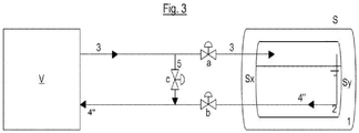
- FIG. 3 A further embodiment is shown in Figure 3 , and again similar components are given the same reference numerals.
- an outlet of the first transfer line 3 into the storage tank S is provided adjacent to a first side wall of the tank S and an inlet of the second transfer line is provide adjacent to a second wall, the second wall being the opposite side of the tank S to the first wall.
- the inlet of the second transfer line 4" (used for transferring the medium from the storage tank S into the liquefaction plant V) is located as far as possible from the outlet of the first transfer line 3.
- the second transfer line 4" is routed so that when the liquid medium is present in the storage tank S, the length of the transfer line 4" which is routed in the section of the inner tank 2 containing the liquid medium is maximized.
- the second transfer line 4" is routed so that, in use, as much of the line 4' is surrounded by the liquid medium as possible.
- the arrangement of the transfer lines 3 and 4 within the storage tank, as represented in Figures 2 and 3 is an improvement of the arrangement of the transfer lines 3 and 4' within the storage tank as represented in Figure 1 . If constructively possible, the arrangement as represented in Figure 2 , even more preferably Figure 3 is thus always selected.
- bypass line 5 is independent of the arrangement of the transfer lines within the storage tank.
- the by-pass line 5 can be provided at any point which connects the first transfer line 3 upstream of shut-off valve a; and the second transfer line 4 downstream of shut-off valve b.
- the by-pass line 5 is provided in the immediate vicinity of, or substantially adjacent to, the storage tank. In practical terms, this means that it is arranged as close as constructively possible to the storage tank. This means that the lengths of those sections of the transfer lines that do not come in direct contact, during the cooling phase, with the medium circulating via the transfer lines and the bypass line are reduced or minimized. In other words, a maximum length of the transfer lines is cooled during the cooling phase, and only the relatively short lengths between the valves and the storage tank are not cooled.
- a cooling of the transfer lines is carried out.
- liquefied medium is led from the liquefaction plant V via the transfer lines 3 and 4/4'/4" as well as the bypass line 5.
- the shut-off valves a and b are closed and only the shut-off valve c of the bypass line 5 is opened. Since the medium used for cooling the transfer lines 3 and 4/4'/4" is now not led through the storage tank S, the heat is effectively prevented from being introduced from the transfer line 3 into the storage tank S.
- the liquefied medium is fed through the by-pass line 5 until a predetermined, desired temperature is reached.
- the shut-off valve c is closed and the shut-off valves a and b are opened. This means that the medium liquefied in the liquefaction plant V is now transferred via the transfer line 3 directly into the storage tank S. At the same time, medium can be transferred from the storage tank S via the transfer line 4/4'/4" back into the liquefaction plant V.
Landscapes
- Engineering & Computer Science (AREA)
- Physics & Mathematics (AREA)
- Mechanical Engineering (AREA)
- Thermal Sciences (AREA)
- General Engineering & Computer Science (AREA)
- Chemical & Material Sciences (AREA)
- Chemical Kinetics & Catalysis (AREA)
- General Chemical & Material Sciences (AREA)
- Oil, Petroleum & Natural Gas (AREA)
- Health & Medical Sciences (AREA)
- Emergency Medicine (AREA)
- Filling Or Discharging Of Gas Storage Vessels (AREA)
Abstract
Description
- The invention relates to an arrangement for liquefying a gaseous medium having at least one storage tank used for storing the liquefied medium. The invention further relates to a method for cooling the transfer lines prior to use.
- The term "liquefaction plant" is understood to mean any plant or any process that is used for cooling and liquefying a gaseous medium, for example, hydrogen, a noble gas such as bhelium, neon, etc., oxygen, nitrogen, a hydrocarbon mixture, in particular natural gas.
- In known arrangements, there is provided at least one liquefaction plant is provided for liquefying a gaseous medium and at least one storage tank which is used to store the liquefied medium. Generally, two transfer lines are provided connected the liquefaction plant and the storage tank. A first transfer line is used to transfer the liquefied medium from the liquefaction plant to the storage tank, and a second transfer line (a return line) is used to transfer flash and boil-off gas of the liquefied medium from the storage tank to the liquefaction plant. It is usual to provide a mechanism, such as a shut-off valve, in each transfer line which can be activate to stop the flow in the transfer line.
- Usually, the transfer lines are vacuum insulated lines. By providing two, distinct and physically separated transfer lines between liquefaction plant and storage tank, it is possible at the same time to transfer liquefied medium from the liquefaction plant into the storage tank and gaseous medium from the storage tank into the liquefaction plant.
- During a standstill phase (non-operational phase) of the liquefaction plant, the transfer lines are heated up due to heat exchange with the environment. Therefore, when the liquefaction plant is started up again it is necessary, to first cool the transfer lines again to an operational temperature which is the temperature corresponding substantially to the temperature of the medium stored in the storage tank. For this purpose, in known arrangements, the liquefied medium is fed from the liquefaction plant via one of the transfer lines into the storage tank and transferred back from said storage tank via the other transfer line back into the liquefaction plant.
- However, at the beginning of this transfer line cooling procedure, the medium flowing from the liquefaction plant into the storage tank and back again into the liquefaction plant absorbs the heat which was introduced into the transfer lines (due to the environmental heat exchange as described above) and conveys this heat into the storage tank and/or into the liquefaction plant. If the storage tank contains any stored liquefied medium during this cooling procedure, undesired evaporation of medium occurs when the inflowing medium and stored liquid medium collide, since a pressure increase in the storage tank occurs due to the density difference between the inflowing and the stored medium. This undesired pressure increase can interfere with the stability of the process and, in addition, it can lead to activation of the mandatory pressure safety system of the storage tank and to the need to drain medium from the storage tank.
- Embodiments of the invention seek to provide an apparatus which overcome some or all of these problems.
- According to a first aspect, there is provided an arrangement comprising
at least one liquefaction plant for liquefying a gaseous medium to produce a liquefied medium; and
at least one storage tank for storing the liquefied medium,
at least one first transfer line connected between the liquefaction plant and the storage tank, for transferring liquefied medium from the liquefaction plant into the storage tank;
at least one second transfer line connected between the liquefaction plant and the storage tank, for transferring gaseous medium from the storage tank into the liquefaction plant, and
at least one shut-off valve provided in each transfer line,
wherein the apparatus further includes
a bypass line connecting at least one first transfer line to at least one second transfer line; and
a bypass shut-off valve provided in the by-pass line,
wherein the bypass line connects the transfer lines at a point between the liquefaction plant and the transfer line shut-off valves. - The apparatus may include one first transfer line and one second transfer line. The by-pass line may connect the first transfer line to the second transfer line.
- The apparatus may comprise multiple first transfer lines and multiple second (return) transfer lines. Where multiple first and second transfer lines are provided, further by pass lines may be provided. For example, a secondary by-pass line may be provided between secondary first and second transfer lines.
- The arrangement may further comprise a control element. The control element may be configured such that after a standstill phase of the liquefaction plant and before the transfer of liquefied medium from the liquefaction plant into the storage tank, it (the control element) carries out a transfer line cooling phase. The cooling phase may include that the control element closes transfer line shut-off valves and opens bypass line shut-off valve, so that liquefied medium is led from the liquefaction plant via partial sections of the transfer lines and the bypass line back into the liquefaction plant.
- The bypass line may be arranged substantially adjacent to the storage tank. The bypass line may be routed so that at least part of its length is substantially parallel to the inner wall of the storage tank. The bypass line may be routed at along the inner wall of the storage tank, a minimal separation such that the line is surrounded in use by the liquefied medium. Advantageously, the bypass line is arranged in the immediate vicinity of the storage tank. The term "arranged in the immediate vicinity of the storage tank" is understood to mean an arrangement of the bypass line in which said bypass line is arranged as close as constructively possible to the storage tank.
- By means of this implementation, the lengths of those sections of the transfer lines that do not come in direct contact, during the cooling phase, with the medium circulating via the transfer lines and the bypass line are reduced or minimized. In other words, a maximum length of the transfer lines is cooled during the cooling phase. This means that only the relatively short length between the valves and the storage tank is not cooled
- The arrangement may further comprise a first transfer line having a first shut-off valve. The arrangement may further comprise a second transfer line having a second shut-off valve. The bypass line may be connected between a point on the first transfer line upstream of the first shut-off valve and a point on the second transfer line downstream of the second shut-off valve.
- The second transfer line used for transferring medium from the storage tank into the liquefaction plant may be arranged so that it is routed at least partially through the area of the storage tank in which the liquefied medium is stored in use.
- An outlet of the first transfer line into the storage tank may be provided adjacent to a first side wall of the tank. An inlet of the second transfer line may be provide adjacent to a second wall, provided on the opposite side of the tank to the first wall.
- The transfer line used for transferring medium from the storage tank into the liquefaction plant may be arranged so that it is not routed through the area of the storage tank in which the liquefied medium is stored in use.
- The storage tank may be a double-walled tank. The storage tank may have an outer tank and an inner tank. The storage tank may be a double-walled, vacuum insulated storage tank.
- At least some of the transfer lines may be vacuum insulated. All least some of the transfer lines may be vacuum insulated.
- According to a second aspect, there is provided a method for cooling the transfer lines of an arrangement as described in any of the statements above after a standstill phase of the liquefaction plant, the method comprising
- operating in a cooling mode which includes
feeding the liquid medium through a by-pass line connected the first transfer line and the second transfer line, so as to by-pass the storage tank, - switching to a normal transfer mode comprising
- transferring the liquefied medium from the liquefaction plant into the storage tank.
- The cooling mode may comprise:
- closing the transfer line shut-off valves, and
- opening the bypass line shut-off valve so that liquefied medium is led from the liquefaction plant via the transfer lines and the bypass line back into the liquefaction plant.
- The cooling mode may be carried out until a predetermined temperature has been reached in at least one defined section of the transfer lines.
- The medium to be liquefied may be hydrogen, a noble gas, in particular helium, neon or argon, oxygen, nitrogen, or a hydrocarbon mixture, more particularly a natural gas
- According to the invention, during the cooling phase, the medium flow circulating through the transfer lines is no longer fed through the storage tank, so that no introduction of heat from the transfer lines to be cooled into the storage tank occurs during the cooling phase. The evaporation of medium stored in the storage tank is thus reduced or completely avoided when the liquefaction plant is started up again, which results in the implementation of a more stable operation of the liquefaction plant, and the risk of activation of the pressure safety system of the storage tank can be reduced.
- Whilst the invention has been described above, it extends to any inventive combination of features set out above or in the following description or drawings.
- Specific embodiments of the invention will now be described in detail by way of example only and with reference to the accompanying drawings in which:
-
Figure 1 shows an arrangement according to a first embodiment of the invention; -
Figure 2 shows an arrangement according to a second embodiment of the invention; and -
Figure 3 shows an arrangement according to a third embodiment of the invention. -
Figures 1, 2 and3 each show a liquefaction plant V represented simply as a black box, as well as a diagrammatically represented storage tank S. -
Figure 1 shows the storage tank S, comprising anouter tank 1 and aninner tank 2, wherein the clearance betweeninner tank 1 andouter tank 2 is vacuum insulated. The arrangement includes afirst transfer line 3 having a shut off valve a; and asecond transfer line 4 having a shut-off valve b. The medium liquefied in the liquefaction plant V is supplied to the storage tank S via thefirst transfer line 3. A gaseous medium is transferred from the storage tank S into the liquefaction plant V via thetransfer line 4. - A by-
pass line 5 is provided between thefirst transfer line 3 and thesecond transfer line 4, and a shut-off valve c is provided in the by-pass line 5. The bypass line connects thefirst transfer line 3 at a point between the liquefaction plant V and the shut-off valve a, to thesecond transfer line 4 at a point between the liquefaction plant V and the shut-off valve b. In other words, the by-pass line is connected to thefirst transfer line 3 upstream of shut-off valve a; and to thesecond transfer line 4 downstream of shut-off valve b. - In
Figure 1 , the second transfer line 4' is arranged in the storage tank S in such a manner that it is not led through the area of the storage tank S or of theinner tank 2 in which the liquid medium is stored. -
Figure 2 shows a different embodiment in which similar components are given the same reference numerals as inFigure 1 . InFigure 2 , the second transfer line 4' used for transferring the medium from the storage tank S into the liquefaction plant V is arranged in such a manner that when the liquid medium is present in the storage tank S (inner tank 2), the line 4' is routed at least partially through the portion of the storage tank S or of theinner tank 2 in which the liquefied medium is stored. - A further embodiment is shown in
Figure 3 , and again similar components are given the same reference numerals. InFigure 3 , an outlet of thefirst transfer line 3 into the storage tank S is provided adjacent to a first side wall of the tank S and an inlet of the second transfer line is provide adjacent to a second wall, the second wall being the opposite side of the tank S to the first wall. This means that the inlet of thesecond transfer line 4" (used for transferring the medium from the storage tank S into the liquefaction plant V) is located as far as possible from the outlet of thefirst transfer line 3. Furthermore, thesecond transfer line 4" is routed so that when the liquid medium is present in the storage tank S, the length of thetransfer line 4" which is routed in the section of theinner tank 2 containing the liquid medium is maximized. In other words, thesecond transfer line 4" is routed so that, in use, as much of the line 4' is surrounded by the liquid medium as possible. - The arrangement of the
transfer lines Figures 2 and3 , is an improvement of the arrangement of thetransfer lines 3 and 4' within the storage tank as represented inFigure 1 . If constructively possible, the arrangement as represented inFigure 2 , even more preferablyFigure 3 is thus always selected. - However, it will be appreciated that the arrangement and use of the
bypass line 5 is independent of the arrangement of the transfer lines within the storage tank. - The by-
pass line 5 can be provided at any point which connects thefirst transfer line 3 upstream of shut-off valve a; and thesecond transfer line 4 downstream of shut-off valve b. However, in a preferred embodiment the by-pass line 5 is provided in the immediate vicinity of, or substantially adjacent to, the storage tank. In practical terms, this means that it is arranged as close as constructively possible to the storage tank. This means that the lengths of those sections of the transfer lines that do not come in direct contact, during the cooling phase, with the medium circulating via the transfer lines and the bypass line are reduced or minimized. In other words, a maximum length of the transfer lines is cooled during the cooling phase, and only the relatively short lengths between the valves and the storage tank are not cooled. - The embodiments of the invention described above are operated in the manner described below.
- After a standstill phase or the renewed startup of the liquefaction plant V, before the transfer of liquefied medium into the storage tank S, a cooling of the transfer lines is carried out. In the transfer lines cooling phase, liquefied medium is led from the liquefaction plant V via the
transfer lines bypass line 5. During this cooling phase, the shut-off valves a and b are closed and only the shut-off valve c of thebypass line 5 is opened. Since the medium used for cooling thetransfer lines transfer line 3 into the storage tank S. The liquefied medium is fed through the by-pass line 5 until a predetermined, desired temperature is reached. - After the cooling of the
transfer lines transfer line 3 directly into the storage tank S. At the same time, medium can be transferred from the storage tank S via thetransfer line 4/4'/4" back into the liquefaction plant V. - While the invention has been described above with reference to one or more preferred embodiments, it will be appreciated that various changes or modifications may be made without departing from the scope of the invention as defined in the appended claims.
Claims (13)
- An arrangement comprising
at least one liquefaction plant (V) for liquefying a gaseous medium to produce a liquefied medium; and
at least one storage tank (S) for storing the liquefied medium,
at least one first transfer line (3) connected between the liquefaction plant (V) and the storage tank (S), for transferring liquefied medium from the liquefaction plant (V) into the storage tank (S);
at least one second transfer line (4, 4', 4") connected between the liquefaction plant (V) and the storage tank (S), for transferring gaseous medium from the storage tank (S) into the liquefaction plant (V), and
at least one shut-off valve (a, b) provided in each transfer line (3, 4, 4', 4"),
wherein the apparatus further includes
a bypass line (5) connecting at least one first transfer line (3) to at least one second transfer lines (3, 4, 4', 4") and
a bypass shut-off valve (c) provided in the by-pass line (5),
wherein the bypass line (5) connects the transfer lines (3, 4, 4', 4") at a point between the liquefaction plant (V) and the transfer line shut-off valves (a, b). - The arrangement according to Claim 1 further comprising a control element, wherein the control element is configured such that after a standstill phase of the liquefaction plant (V) and before the transfer of liquefied medium from the liquefaction plant (V) into the storage tank (S), it carries out a transfer line cooling phase, in which it closes transfer line shut-off valves (a, b) and opens bypass line shut-off valve (c), so that liquefied medium is led from the liquefaction plant (V) via partial sections of the transfer lines (3, 4, 4', 4") and the bypass line (5) back into the liquefaction plant (V).
- The arrangement according to Claim 1 or claim 2, wherein the bypass line (5) is arranged substantially adjacent to the storage tank (S).
- The arrangement according to any of the previous claims, comprising a first transfer line (3) having a first shut-off valve (a), and a second transfer line (4, 4', 4") having a second shut-off valve (b),
wherein the bypass line (5) is connected between a point on the first transfer line (3) upstream of the first shut-off valve (a) and a point on the second transfer line (4, 4', 4") downstream of the second shut-off valve (b) - The arrangement according to any of the previous claims, wherein the second transfer line (4', 4") used for transferring medium from the storage tank (S) into the liquefaction plant (V) is arranged so that it is routed at least partially through the area of the storage tank (S) in which the liquefied medium is stored in use.
- The arrangement according to claim 5, wherein an outlet of the first transfer line (3) into the storage tank (S) is provided adjacent to a first side wall of the tank (S) and an inlet of the second transfer line is provide adjacent to a second wall, provided on the opposite side of the tank (S) to the first wall.
- The arrangement according to any of the previous claims, wherein the transfer line (4') used for transferring medium from the storage tank (S) into the liquefaction plant (V) is arranged so that it is not routed through the area of the storage tank (S) in which the liquefied medium is stored in use.
- The arrangement according to any of the previous claims, wherein the storage tank (S) is a double-walled tank, having an outer tank (1) and an inner tank (2), preferably a vacuum insulated storage tank.
- The arrangement according to any of the previous claims, wherein at least some of the transfer lines are vacuum insulated.
- A method for cooling the transfer lines (3, 4, 4') of an arrangement according to any one of the preceding claims after a standstill phase of the liquefaction plant (V), the method comprising:- operating in a cooling mode which includes
feeding the liquid medium through a by-pass line connected the first transfer line and the second transfer line, so as to by-pass the storage tank (S)- switching to a normal transfer mode comprising- transferring the liquefied medium from the liquefaction plant (V) into the storage tank (S). - The method according to claim 10, wherein the cooling mode comprises:- closing the transfer line shut-off valves (a, b) and- opening the bypass line shut-off valve (c), so that liquefied medium is led from the liquefaction plant (V) via the transfer lines (3, 4, 4') and the bypass line (5) back into the liquefaction plant (V)
- The method according to Claim 10, wherein the cooling mode is carried out until a predetermined temperature has been reached in at least one defined section of the transfer lines (3, 4, 4', 4').
- The method according to any of claims 10 to 12, wherein the medium to be liquefied is hydrogen, a noble gas, in particular helium, neon or argon, oxygen, nitrogen, or a hydrocarbon mixture, more particularly a natural gas.
Applications Claiming Priority (1)
| Application Number | Priority Date | Filing Date | Title |
|---|---|---|---|
| GBGB1711975.1A GB201711975D0 (en) | 2017-07-25 | 2017-07-25 | Liquiefying a gaseous medium |
Publications (1)
| Publication Number | Publication Date |
|---|---|
| EP3435015A1 true EP3435015A1 (en) | 2019-01-30 |
Family
ID=59771588
Family Applications (1)
| Application Number | Title | Priority Date | Filing Date |
|---|---|---|---|
| EP18185045.4A Withdrawn EP3435015A1 (en) | 2017-07-25 | 2018-07-23 | Liquiefying a gaseous medium |
Country Status (3)
| Country | Link |
|---|---|
| US (1) | US10976102B2 (en) |
| EP (1) | EP3435015A1 (en) |
| GB (1) | GB201711975D0 (en) |
Cited By (1)
| Publication number | Priority date | Publication date | Assignee | Title |
|---|---|---|---|---|
| CN112460916A (en) * | 2020-11-24 | 2021-03-09 | 张海美 | High-efficiency industrial oxygen generation system and oxygen generation process |
Families Citing this family (1)
| Publication number | Priority date | Publication date | Assignee | Title |
|---|---|---|---|---|
| CN108728196A (en) * | 2018-07-20 | 2018-11-02 | 西安长庆科技工程有限责任公司 | A kind of associated gas liquid separation metering integrated integrating device and its application process |
Citations (8)
| Publication number | Priority date | Publication date | Assignee | Title |
|---|---|---|---|---|
| FR1414480A (en) * | 1964-04-10 | 1965-10-15 | Lummus Co | Gas liquefaction process |
| FR1448598A (en) * | 1964-09-30 | 1966-08-05 | Philips Nv | Liquefaction plant for a gas mixture |
| JPS5862483A (en) * | 1981-10-09 | 1983-04-13 | 株式会社ほくさん | Liquefier for he gas |
| US4675037A (en) * | 1986-02-18 | 1987-06-23 | Air Products And Chemicals, Inc. | Apparatus and method for recovering liquefied natural gas vapor boiloff by reliquefying during startup or turndown |
| JP2000291892A (en) * | 1999-04-02 | 2000-10-20 | Yazaki Corp | Bulk supply equipment |
| US20060213223A1 (en) * | 2001-05-04 | 2006-09-28 | Battelle Energy Alliance, Llc | Apparatus for the liquefaction of natural gas and methods relating to same |
| WO2006118458A2 (en) * | 2005-05-04 | 2006-11-09 | Single Buoy Moorings Inc. | Large distance offshore lng export terminal with boil-off vapour collection and utilization capacities |
| US20080197137A1 (en) * | 2007-02-16 | 2008-08-21 | Harald Schlag | Cryogenic storage tank with thermal shield |
Family Cites Families (3)
| Publication number | Priority date | Publication date | Assignee | Title |
|---|---|---|---|---|
| GB0320474D0 (en) * | 2003-09-01 | 2003-10-01 | Cryostar France Sa | Controlled storage of liquefied gases |
| US20090071171A1 (en) * | 2007-09-18 | 2009-03-19 | Jalal Hunain Zia | Cryogenic liquid storage method and system |
| JP6703837B2 (en) * | 2016-01-07 | 2020-06-03 | 株式会社神戸製鋼所 | Boil-off gas supply device |
-
2017
- 2017-07-25 GB GBGB1711975.1A patent/GB201711975D0/en not_active Ceased
-
2018
- 2018-07-23 EP EP18185045.4A patent/EP3435015A1/en not_active Withdrawn
- 2018-07-24 US US16/043,742 patent/US10976102B2/en not_active Expired - Fee Related
Patent Citations (8)
| Publication number | Priority date | Publication date | Assignee | Title |
|---|---|---|---|---|
| FR1414480A (en) * | 1964-04-10 | 1965-10-15 | Lummus Co | Gas liquefaction process |
| FR1448598A (en) * | 1964-09-30 | 1966-08-05 | Philips Nv | Liquefaction plant for a gas mixture |
| JPS5862483A (en) * | 1981-10-09 | 1983-04-13 | 株式会社ほくさん | Liquefier for he gas |
| US4675037A (en) * | 1986-02-18 | 1987-06-23 | Air Products And Chemicals, Inc. | Apparatus and method for recovering liquefied natural gas vapor boiloff by reliquefying during startup or turndown |
| JP2000291892A (en) * | 1999-04-02 | 2000-10-20 | Yazaki Corp | Bulk supply equipment |
| US20060213223A1 (en) * | 2001-05-04 | 2006-09-28 | Battelle Energy Alliance, Llc | Apparatus for the liquefaction of natural gas and methods relating to same |
| WO2006118458A2 (en) * | 2005-05-04 | 2006-11-09 | Single Buoy Moorings Inc. | Large distance offshore lng export terminal with boil-off vapour collection and utilization capacities |
| US20080197137A1 (en) * | 2007-02-16 | 2008-08-21 | Harald Schlag | Cryogenic storage tank with thermal shield |
Cited By (2)
| Publication number | Priority date | Publication date | Assignee | Title |
|---|---|---|---|---|
| CN112460916A (en) * | 2020-11-24 | 2021-03-09 | 张海美 | High-efficiency industrial oxygen generation system and oxygen generation process |
| CN112460916B (en) * | 2020-11-24 | 2022-03-29 | 辽宁帅兴气体有限责任公司 | High-efficiency industrial oxygen generation system and oxygen generation process |
Also Published As
| Publication number | Publication date |
|---|---|
| GB201711975D0 (en) | 2017-09-06 |
| US20190032995A1 (en) | 2019-01-31 |
| US10976102B2 (en) | 2021-04-13 |
Similar Documents
| Publication | Publication Date | Title |
|---|---|---|
| US10760740B2 (en) | Liquiefying a gaseous medium | |
| KR20160055830A (en) | Device for recovering vapours from a cryogenic tank | |
| JP2007511717A (en) | Apparatus and method for boil-off gas temperature control | |
| EP3431382B1 (en) | Ship having gas regasification system | |
| JP6834999B2 (en) | Evaporative gas suppression device and evaporative gas suppression method for LNG tanks | |
| JP5448123B2 (en) | Method and system for handling warm LPG loads | |
| JP6994464B2 (en) | How to operate the liquefied gas storage tank and the liquefied gas storage tank for receiving LNG and boil-off gas | |
| KR102619112B1 (en) | Fuel supply apparatus for liquefied natural gas carrier | |
| CN111755716A (en) | Fuel extraction system, fuel tank apparatus having fuel extraction system, and fuel cell system having fuel extraction system | |
| US10976102B2 (en) | Liquiefying a gaseous medium | |
| JPS62192493A (en) | Revaporization of liquefied natural gas for boil off gas reliquefying machine | |
| CN116710725B (en) | Gas supply system for high-pressure and low-pressure gas consumers | |
| JP2021516749A (en) | Gas supply assembly | |
| JP2021167671A (en) | Device and method for filling pressurized gas tank | |
| KR20190041859A (en) | Reliquefaction apparatus of liquified gas using fuel LNG and liquefied gas carrier having the same | |
| JP2024511643A (en) | Method for cooling heat exchangers of gas supply systems for gas consumers of ships | |
| KR102200365B1 (en) | Volatile organic compounds treatment system and ship having the same | |
| JP2007292181A (en) | BOG suppression method for liquefied gas equipment | |
| KR20150063008A (en) | Fuel gas supply system and method for ship | |
| JP2018103954A (en) | Ship | |
| KR20250114407A (en) | liquefied hydrogen facility | |
| CN114729779B (en) | System for treating gas contained in tanks for storing and/or transporting gas | |
| KR102920356B1 (en) | A system installed on a ship to process gas contained in a tank for storing and/or transporting liquid and gaseous gases. | |
| US20250305636A1 (en) | Gas supply system for high and low pressure gas consumer appliances | |
| KR102433264B1 (en) | gas treatment system and offshore plant having the same |
Legal Events
| Date | Code | Title | Description |
|---|---|---|---|
| PUAI | Public reference made under article 153(3) epc to a published international application that has entered the european phase |
Free format text: ORIGINAL CODE: 0009012 |
|
| STAA | Information on the status of an ep patent application or granted ep patent |
Free format text: STATUS: THE APPLICATION HAS BEEN PUBLISHED |
|
| AK | Designated contracting states |
Kind code of ref document: A1 Designated state(s): AL AT BE BG CH CY CZ DE DK EE ES FI FR GB GR HR HU IE IS IT LI LT LU LV MC MK MT NL NO PL PT RO RS SE SI SK SM TR |
|
| AX | Request for extension of the european patent |
Extension state: BA ME |
|
| STAA | Information on the status of an ep patent application or granted ep patent |
Free format text: STATUS: REQUEST FOR EXAMINATION WAS MADE |
|
| 17P | Request for examination filed |
Effective date: 20190726 |
|
| RBV | Designated contracting states (corrected) |
Designated state(s): AL AT BE BG CH CY CZ DE DK EE ES FI FR GB GR HR HU IE IS IT LI LT LU LV MC MK MT NL NO PL PT RO RS SE SI SK SM TR |
|
| RAP1 | Party data changed (applicant data changed or rights of an application transferred) |
Owner name: LINDE GMBH |
|
| STAA | Information on the status of an ep patent application or granted ep patent |
Free format text: STATUS: EXAMINATION IS IN PROGRESS |
|
| 17Q | First examination report despatched |
Effective date: 20220721 |
|
| STAA | Information on the status of an ep patent application or granted ep patent |
Free format text: STATUS: THE APPLICATION IS DEEMED TO BE WITHDRAWN |
|
| 18D | Application deemed to be withdrawn |
Effective date: 20250201 |