EP3434974A1 - Thermal power generation system and control method for same - Google Patents
Thermal power generation system and control method for same Download PDFInfo
- Publication number
- EP3434974A1 EP3434974A1 EP17769763.8A EP17769763A EP3434974A1 EP 3434974 A1 EP3434974 A1 EP 3434974A1 EP 17769763 A EP17769763 A EP 17769763A EP 3434974 A1 EP3434974 A1 EP 3434974A1
- Authority
- EP
- European Patent Office
- Prior art keywords
- exhaust gas
- feed water
- pressure feed
- disposed
- water heater
- Prior art date
- Legal status (The legal status is an assumption and is not a legal conclusion. Google has not performed a legal analysis and makes no representation as to the accuracy of the status listed.)
- Granted
Links
Images


Classifications
-
- F—MECHANICAL ENGINEERING; LIGHTING; HEATING; WEAPONS; BLASTING
- F01—MACHINES OR ENGINES IN GENERAL; ENGINE PLANTS IN GENERAL; STEAM ENGINES
- F01K—STEAM ENGINE PLANTS; STEAM ACCUMULATORS; ENGINE PLANTS NOT OTHERWISE PROVIDED FOR; ENGINES USING SPECIAL WORKING FLUIDS OR CYCLES
- F01K9/00—Plants characterised by condensers arranged or modified to co-operate with the engines
- F01K9/02—Arrangements or modifications of condensate or air pumps
- F01K9/023—Control thereof
-
- B—PERFORMING OPERATIONS; TRANSPORTING
- B01—PHYSICAL OR CHEMICAL PROCESSES OR APPARATUS IN GENERAL
- B01D—SEPARATION
- B01D53/00—Separation of gases or vapours; Recovering vapours of volatile solvents from gases; Chemical or biological purification of waste gases, e.g. engine exhaust gases, smoke, fumes, flue gases, aerosols
- B01D53/34—Chemical or biological purification of waste gases
- B01D53/74—General processes for purification of waste gases; Apparatus or devices specially adapted therefor
- B01D53/86—Catalytic processes
- B01D53/8621—Removing nitrogen compounds
- B01D53/8625—Nitrogen oxides
- B01D53/8631—Processes characterised by a specific device
-
- B—PERFORMING OPERATIONS; TRANSPORTING
- B01—PHYSICAL OR CHEMICAL PROCESSES OR APPARATUS IN GENERAL
- B01D—SEPARATION
- B01D53/00—Separation of gases or vapours; Recovering vapours of volatile solvents from gases; Chemical or biological purification of waste gases, e.g. engine exhaust gases, smoke, fumes, flue gases, aerosols
- B01D53/34—Chemical or biological purification of waste gases
- B01D53/74—General processes for purification of waste gases; Apparatus or devices specially adapted therefor
- B01D53/86—Catalytic processes
- B01D53/8665—Removing heavy metals or compounds thereof, e.g. mercury
-
- B—PERFORMING OPERATIONS; TRANSPORTING
- B01—PHYSICAL OR CHEMICAL PROCESSES OR APPARATUS IN GENERAL
- B01D—SEPARATION
- B01D53/00—Separation of gases or vapours; Recovering vapours of volatile solvents from gases; Chemical or biological purification of waste gases, e.g. engine exhaust gases, smoke, fumes, flue gases, aerosols
- B01D53/34—Chemical or biological purification of waste gases
- B01D53/74—General processes for purification of waste gases; Apparatus or devices specially adapted therefor
- B01D53/86—Catalytic processes
- B01D53/8696—Controlling the catalytic process
-
- F—MECHANICAL ENGINEERING; LIGHTING; HEATING; WEAPONS; BLASTING
- F01—MACHINES OR ENGINES IN GENERAL; ENGINE PLANTS IN GENERAL; STEAM ENGINES
- F01K—STEAM ENGINE PLANTS; STEAM ACCUMULATORS; ENGINE PLANTS NOT OTHERWISE PROVIDED FOR; ENGINES USING SPECIAL WORKING FLUIDS OR CYCLES
- F01K11/00—Plants characterised by the engines being structurally combined with boilers or condensers
- F01K11/02—Plants characterised by the engines being structurally combined with boilers or condensers the engines being turbines
-
- F—MECHANICAL ENGINEERING; LIGHTING; HEATING; WEAPONS; BLASTING
- F01—MACHINES OR ENGINES IN GENERAL; ENGINE PLANTS IN GENERAL; STEAM ENGINES
- F01K—STEAM ENGINE PLANTS; STEAM ACCUMULATORS; ENGINE PLANTS NOT OTHERWISE PROVIDED FOR; ENGINES USING SPECIAL WORKING FLUIDS OR CYCLES
- F01K13/00—General layout or general methods of operation of complete plants
- F01K13/02—Controlling, e.g. stopping or starting
-
- F—MECHANICAL ENGINEERING; LIGHTING; HEATING; WEAPONS; BLASTING
- F01—MACHINES OR ENGINES IN GENERAL; ENGINE PLANTS IN GENERAL; STEAM ENGINES
- F01K—STEAM ENGINE PLANTS; STEAM ACCUMULATORS; ENGINE PLANTS NOT OTHERWISE PROVIDED FOR; ENGINES USING SPECIAL WORKING FLUIDS OR CYCLES
- F01K7/00—Steam engine plants characterised by the use of specific types of engine; Plants or engines characterised by their use of special steam systems, cycles or processes; Control means specially adapted for such systems, cycles or processes; Use of withdrawn or exhaust steam for feed-water heating
- F01K7/16—Steam engine plants characterised by the use of specific types of engine; Plants or engines characterised by their use of special steam systems, cycles or processes; Control means specially adapted for such systems, cycles or processes; Use of withdrawn or exhaust steam for feed-water heating the engines being only of turbine type
- F01K7/18—Steam engine plants characterised by the use of specific types of engine; Plants or engines characterised by their use of special steam systems, cycles or processes; Control means specially adapted for such systems, cycles or processes; Use of withdrawn or exhaust steam for feed-water heating the engines being only of turbine type the turbine being of multiple-inlet-pressure type
- F01K7/20—Control means specially adapted therefor
-
- F—MECHANICAL ENGINEERING; LIGHTING; HEATING; WEAPONS; BLASTING
- F01—MACHINES OR ENGINES IN GENERAL; ENGINE PLANTS IN GENERAL; STEAM ENGINES
- F01K—STEAM ENGINE PLANTS; STEAM ACCUMULATORS; ENGINE PLANTS NOT OTHERWISE PROVIDED FOR; ENGINES USING SPECIAL WORKING FLUIDS OR CYCLES
- F01K7/00—Steam engine plants characterised by the use of specific types of engine; Plants or engines characterised by their use of special steam systems, cycles or processes; Control means specially adapted for such systems, cycles or processes; Use of withdrawn or exhaust steam for feed-water heating
- F01K7/16—Steam engine plants characterised by the use of specific types of engine; Plants or engines characterised by their use of special steam systems, cycles or processes; Control means specially adapted for such systems, cycles or processes; Use of withdrawn or exhaust steam for feed-water heating the engines being only of turbine type
- F01K7/22—Steam engine plants characterised by the use of specific types of engine; Plants or engines characterised by their use of special steam systems, cycles or processes; Control means specially adapted for such systems, cycles or processes; Use of withdrawn or exhaust steam for feed-water heating the engines being only of turbine type the turbines having inter-stage steam heating
-
- F—MECHANICAL ENGINEERING; LIGHTING; HEATING; WEAPONS; BLASTING
- F01—MACHINES OR ENGINES IN GENERAL; ENGINE PLANTS IN GENERAL; STEAM ENGINES
- F01K—STEAM ENGINE PLANTS; STEAM ACCUMULATORS; ENGINE PLANTS NOT OTHERWISE PROVIDED FOR; ENGINES USING SPECIAL WORKING FLUIDS OR CYCLES
- F01K7/00—Steam engine plants characterised by the use of specific types of engine; Plants or engines characterised by their use of special steam systems, cycles or processes; Control means specially adapted for such systems, cycles or processes; Use of withdrawn or exhaust steam for feed-water heating
- F01K7/34—Steam engine plants characterised by the use of specific types of engine; Plants or engines characterised by their use of special steam systems, cycles or processes; Control means specially adapted for such systems, cycles or processes; Use of withdrawn or exhaust steam for feed-water heating the engines being of extraction or non-condensing type; Use of steam for feed-water heating
- F01K7/38—Steam engine plants characterised by the use of specific types of engine; Plants or engines characterised by their use of special steam systems, cycles or processes; Control means specially adapted for such systems, cycles or processes; Use of withdrawn or exhaust steam for feed-water heating the engines being of extraction or non-condensing type; Use of steam for feed-water heating the engines being of turbine type
-
- F—MECHANICAL ENGINEERING; LIGHTING; HEATING; WEAPONS; BLASTING
- F01—MACHINES OR ENGINES IN GENERAL; ENGINE PLANTS IN GENERAL; STEAM ENGINES
- F01K—STEAM ENGINE PLANTS; STEAM ACCUMULATORS; ENGINE PLANTS NOT OTHERWISE PROVIDED FOR; ENGINES USING SPECIAL WORKING FLUIDS OR CYCLES
- F01K7/00—Steam engine plants characterised by the use of specific types of engine; Plants or engines characterised by their use of special steam systems, cycles or processes; Control means specially adapted for such systems, cycles or processes; Use of withdrawn or exhaust steam for feed-water heating
- F01K7/34—Steam engine plants characterised by the use of specific types of engine; Plants or engines characterised by their use of special steam systems, cycles or processes; Control means specially adapted for such systems, cycles or processes; Use of withdrawn or exhaust steam for feed-water heating the engines being of extraction or non-condensing type; Use of steam for feed-water heating
- F01K7/40—Use of two or more feed-water heaters in series
-
- F—MECHANICAL ENGINEERING; LIGHTING; HEATING; WEAPONS; BLASTING
- F22—STEAM GENERATION
- F22D—PREHEATING, OR ACCUMULATING PREHEATED, FEED-WATER FOR STEAM GENERATION; FEED-WATER SUPPLY FOR STEAM GENERATION; CONTROLLING WATER LEVEL FOR STEAM GENERATION; AUXILIARY DEVICES FOR PROMOTING WATER CIRCULATION WITHIN STEAM BOILERS
- F22D1/00—Feed-water heaters, i.e. economisers or like preheaters
- F22D1/02—Feed-water heaters, i.e. economisers or like preheaters with water tubes arranged in the boiler furnaces, fire tubes or flue ways
- F22D1/12—Control devices, e.g. for regulating steam temperature
-
- F—MECHANICAL ENGINEERING; LIGHTING; HEATING; WEAPONS; BLASTING
- F22—STEAM GENERATION
- F22D—PREHEATING, OR ACCUMULATING PREHEATED, FEED-WATER FOR STEAM GENERATION; FEED-WATER SUPPLY FOR STEAM GENERATION; CONTROLLING WATER LEVEL FOR STEAM GENERATION; AUXILIARY DEVICES FOR PROMOTING WATER CIRCULATION WITHIN STEAM BOILERS
- F22D1/00—Feed-water heaters, i.e. economisers or like preheaters
- F22D1/32—Feed-water heaters, i.e. economisers or like preheaters arranged to be heated by steam, e.g. bled from turbines
- F22D1/325—Schematic arrangements or control devices therefor
-
- F—MECHANICAL ENGINEERING; LIGHTING; HEATING; WEAPONS; BLASTING
- F22—STEAM GENERATION
- F22D—PREHEATING, OR ACCUMULATING PREHEATED, FEED-WATER FOR STEAM GENERATION; FEED-WATER SUPPLY FOR STEAM GENERATION; CONTROLLING WATER LEVEL FOR STEAM GENERATION; AUXILIARY DEVICES FOR PROMOTING WATER CIRCULATION WITHIN STEAM BOILERS
- F22D1/00—Feed-water heaters, i.e. economisers or like preheaters
- F22D1/32—Feed-water heaters, i.e. economisers or like preheaters arranged to be heated by steam, e.g. bled from turbines
- F22D1/34—Feed-water heaters, i.e. economisers or like preheaters arranged to be heated by steam, e.g. bled from turbines and returning condensate to boiler with main feed supply
-
- F—MECHANICAL ENGINEERING; LIGHTING; HEATING; WEAPONS; BLASTING
- F23—COMBUSTION APPARATUS; COMBUSTION PROCESSES
- F23J—REMOVAL OR TREATMENT OF COMBUSTION PRODUCTS OR COMBUSTION RESIDUES; FLUES
- F23J15/00—Arrangements of devices for treating smoke or fumes
- F23J15/006—Layout of treatment plant
-
- B—PERFORMING OPERATIONS; TRANSPORTING
- B01—PHYSICAL OR CHEMICAL PROCESSES OR APPARATUS IN GENERAL
- B01D—SEPARATION
- B01D2257/00—Components to be removed
- B01D2257/40—Nitrogen compounds
-
- B—PERFORMING OPERATIONS; TRANSPORTING
- B01—PHYSICAL OR CHEMICAL PROCESSES OR APPARATUS IN GENERAL
- B01D—SEPARATION
- B01D2257/00—Components to be removed
- B01D2257/60—Heavy metals or heavy metal compounds
- B01D2257/602—Mercury or mercury compounds
-
- B—PERFORMING OPERATIONS; TRANSPORTING
- B01—PHYSICAL OR CHEMICAL PROCESSES OR APPARATUS IN GENERAL
- B01D—SEPARATION
- B01D2258/00—Sources of waste gases
- B01D2258/02—Other waste gases
-
- B—PERFORMING OPERATIONS; TRANSPORTING
- B01—PHYSICAL OR CHEMICAL PROCESSES OR APPARATUS IN GENERAL
- B01D—SEPARATION
- B01D2258/00—Sources of waste gases
- B01D2258/02—Other waste gases
- B01D2258/0283—Flue gases
-
- F—MECHANICAL ENGINEERING; LIGHTING; HEATING; WEAPONS; BLASTING
- F01—MACHINES OR ENGINES IN GENERAL; ENGINE PLANTS IN GENERAL; STEAM ENGINES
- F01K—STEAM ENGINE PLANTS; STEAM ACCUMULATORS; ENGINE PLANTS NOT OTHERWISE PROVIDED FOR; ENGINES USING SPECIAL WORKING FLUIDS OR CYCLES
- F01K7/00—Steam engine plants characterised by the use of specific types of engine; Plants or engines characterised by their use of special steam systems, cycles or processes; Control means specially adapted for such systems, cycles or processes; Use of withdrawn or exhaust steam for feed-water heating
- F01K7/16—Steam engine plants characterised by the use of specific types of engine; Plants or engines characterised by their use of special steam systems, cycles or processes; Control means specially adapted for such systems, cycles or processes; Use of withdrawn or exhaust steam for feed-water heating the engines being only of turbine type
-
- F—MECHANICAL ENGINEERING; LIGHTING; HEATING; WEAPONS; BLASTING
- F23—COMBUSTION APPARATUS; COMBUSTION PROCESSES
- F23J—REMOVAL OR TREATMENT OF COMBUSTION PRODUCTS OR COMBUSTION RESIDUES; FLUES
- F23J2215/00—Preventing emissions
- F23J2215/10—Nitrogen; Compounds thereof
- F23J2215/101—Nitrous oxide (N2O)
-
- F—MECHANICAL ENGINEERING; LIGHTING; HEATING; WEAPONS; BLASTING
- F23—COMBUSTION APPARATUS; COMBUSTION PROCESSES
- F23J—REMOVAL OR TREATMENT OF COMBUSTION PRODUCTS OR COMBUSTION RESIDUES; FLUES
- F23J2215/00—Preventing emissions
- F23J2215/60—Heavy metals; Compounds thereof
-
- F—MECHANICAL ENGINEERING; LIGHTING; HEATING; WEAPONS; BLASTING
- F23—COMBUSTION APPARATUS; COMBUSTION PROCESSES
- F23J—REMOVAL OR TREATMENT OF COMBUSTION PRODUCTS OR COMBUSTION RESIDUES; FLUES
- F23J2219/00—Treatment devices
- F23J2219/10—Catalytic reduction devices
Definitions
- the present disclosure relates to a thermal power generation system and a method of controlling the same.
- Patent Document 1 discloses an exhaust-gas treatment apparatus including a cooling device disposed upstream of a denitration catalyst and configured to control the temperature of exhaust gas to a predetermined temperature of 300 to 400°C. Furthermore, exhaust gas controlled by a cooling device to have a predetermined temperature is guided to the denitration catalyst to reduce and remove nitrogen oxide in the exhaust gas, while metallic mercury in the exhaust gas is caused to react with hydrogen chloride to produce mercury chloride.
- a desulfurization apparatus disposed downstream of the denitration catalyst removes the mercury chloride from exhaust gas, by dissolving the mercury chloride into an absorbing solution. Accordingly, with the exhaust gas treatment device disclosed in Patent Document 1, it is possible to improve the efficiency of removing mercury from exhaust gas.
- Patent Document 1 JP2007-167698A
- an object of at least one embodiment of the present invention is to provide a thermal power generation system and a method of controlling a thermal power generation system, whereby it is possible to adjust the temperature of exhaust gas at a catalyst device and remove metallic mercury from exhaust gas efficiently, with a simple configuration.
- the exhaust gas temperature adjustment device is capable of adjusting the temperature of exhaust gas at the catalyst device by adjusting heating of water by the at least one high-pressure feed water heater.
- the exhaust gas temperature adjustment device adjusts the opening degree of the at least one bypass valve on the basis of the measurement result of the exhaust gas temperature sensor, and thereby it is possible to adjust the temperature of exhaust gas at the catalyst device appropriately, and remove metallic mercury from exhaust gas efficiently.
- the exhaust gas temperature adjustment device adjusts the opening degree of the extraction valve on the basis of the measurement result of the exhaust gas temperature sensor, and thereby it is possible to adjust the temperature of exhaust gas at the catalyst device appropriately, and remove metallic mercury from exhaust gas efficiently.
- the exhaust gas temperature adjustment device is configured to adjust the temperature of exhaust gas at the catalyst device to 420°C or below, and thus it is possible to maintain the chemical equilibrium between metallic mercury and mercuric oxide in a state where the proportion of metallic mercury is relatively small, which makes it possible to remove mercury from exhaust gas reliably and efficiently.
- the reduction reaction of nitrogen oxide proceeds smoothly when the temperature of exhaust gas at the catalyst device is 290°C or higher, or more preferably, 320°C or higher.
- the temperature of exhaust gas is lower than 320°C, depending on the concentration of SOx in exhaust gas or concentration of NH 3 injected to achieve the necessary denitration function, acidic ammonium sulfate may be deposited on the catalyst, which may lead to reduction of the activity of the catalyst.
- the oxidization reaction of mercury may fail to proceed smoothly.
- the exhaust gas temperature adjustment device is configured to adjust the temperature of exhaust gas at the catalyst device to 290°C or higher, or preferably, 320°C or higher, and thus it is possible to remove nitrogen oxide from exhaust gas reliably and efficiently, and remove metallic mercury from exhaust gas reliably and efficiently.
- thermo power generation system and a method of controlling a thermal power generation system, capable of adjusting the temperature of exhaust gas with a catalyst device and removing metallic mercury from exhaust gas efficiently, with a simplified configuration.
- an expression of relative or absolute arrangement such as “in a direction”, “along a direction”, “parallel”, “orthogonal”, “centered”, “concentric” and “coaxial” shall not be construed as indicating only the arrangement in a strict literal sense, but also includes a state where the arrangement is relatively displaced by a tolerance, or by an angle or a distance whereby it is possible to achieve the same function.
- an expression of an equal state such as “same” “equal” and “uniform” shall not be construed as indicating only the state in which the feature is strictly equal, but also includes a state in which there is a tolerance or a difference that can still achieve the same function.
- an expression of a shape such as a rectangular shape or a cylindrical shape shall not be construed as only the geometrically strict shape, but also includes a shape with unevenness or chamfered corners within the range in which the same effect can be achieved.
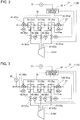
- FIG. 1 is a schematic diagram of a thermal power generation system 1A according to an embodiment of the present invention.
- FIG. 2 is a schematic partial diagram of a configuration of a thermal power generation system 1B according to another embodiment of the present invention.
- FIG. 3 is a schematic partial diagram of a configuration of a thermal power generation system 1C according to yet another embodiment of the present invention.
- FIG. 4 is a schematic partial diagram of a configuration of a thermal power generation system 1D according to yet another embodiment of the present invention.
- FIG. 5 is a schematic partial diagram of a configuration of a thermal power generation system 1E according to yet another embodiment of the present invention.
- thermal power generation systems 1A to 1E may be referred to as a thermal power generation system 1, collectively.
- the thermal power generation system 1 includes a boiler 3, at least one steam turbine 5, a generator 7, a condenser 9, at least one low-pressure feed water heater 11, a high-pressure feed water pump 13, at least one high-pressure feed water heater 15, a catalyst device 17, a mercuric oxide removing device 19, and an exhaust gas temperature adjustment device 21.
- the boiler 3 is capable of producing high-temperature combustion gas (exhaust gas) by combusting fuel such as coal by utilizing air.
- the boiler 3 includes at least one internal heat exchanger 23, which is disposed in a circulation passage 25 through which water can circulate.
- the at least one internal heat exchanger 23 is capable of exchanging heat between exhaust gas and water, and of producing steam through heat exchange between water and exhaust gas produced by combusting fuel.
- the at least one internal heat exchanger 23 includes an economizer 23a, an evaporator (evaporating tube) 23b, a super-heater 23c, and a re-heater 23d.
- the economizer 23a, the evaporator 23b, the super-heater 23c, and the re-heater 23d are disposed in the circulation passage 25 in the flow direction of water (circulation direction).
- At least one steam turbine 5 is disposed in the circulation passage 25, and is capable of outputting power by utilizing steam.
- the at least one steam turbine 5 includes a high-pressure turbine 5a, an intermediate-pressure turbine 5b, and a low-pressure turbine 5c.
- the high-pressure turbine 5a, the intermediate-pressure turbine 5b, and the low-pressure turbine 5c are disposed in the circulation passage 25 in this order in the flow direction of water (circulation direction).
- the high-pressure turbine 5a is disposed downstream of the super-heater 23c.
- the re-heater 23d is disposed between the high-pressure turbine 5a and the intermediate-pressure turbine 5b.
- the generator 7 is coupled to the at least one steam turbine 5, and is capable of generating electric power by utilizing power outputted from the steam turbine 5.
- the condenser 9 is capable of condensing steam discharged from the at least one steam turbine 5.
- the at least one low-pressure feed water heater 11 is disposed in a feed water path 27 forming a part of the circulation passage 25.
- the feed water path 27 extends between the condenser 9 and the at least one internal heat exchanger 23, and is for supplying liquid-phase water to the internal heat exchanger 23.
- the at least one low-pressure feed water heater 11 is capable of heating water condensed by the condenser 9, by utilizing steam extracted from the steam turbine 5.
- the number of low-pressure feed water heater 11 is not particularly limited.
- the low-pressure feed water heater 11 may include the first low-pressure feed water heater 11a, the second low-pressure feed water heater 11b, and the third low-pressure feed water heater 11c.
- the first low-pressure feed water heater 11a, the second low-pressure feed water heater 11b, and the third low-pressure feed water heater 11c may be supplied with steam S1, S2, S3, respectively, extracted from the low-pressure turbine 5c, for instance.
- the at least one low-pressure feed water heater 11 is a mixing type feed water heater, in which water flowing through the feed water path 27 and steam supplied to heat water are mixed.
- the high-pressure feed water pump 13 is disposed in the feed water path 27 of the circulation passage 25, and is positioned downstream of the low-pressure feed water heater 11 in the flow direction of water (circulation direction).
- the high-pressure feed water pump 13 is capable of increasing the pressure of water heated by the low-pressure feed water heater 11 to pump the water.
- the at least one high-pressure feed water heater 15 is disposed in the feed water path 27 of the circulation passage 25, and is positioned between the high-pressure feed water pump 13 and the at least one internal heat exchanger 23.
- the high-pressure feed water heater 15 is capable of heating water pumped by the high-pressure feed water pump 13, by utilizing steam extracted from the at least one steam turbine 5.
- the number of high-pressure feed water heater 15 is not particularly limited.
- the high-pressure feed water heater 15 may include the first high-pressure feed water heater 15a, the second high-pressure feed water heater 15b, and the third high-pressure feed water heater 15c.
- the first high-pressure feed water heater 15a, the second high-pressure feed water heater 15b, and the third high-pressure feed water heater 15c may be supplied with steam S4, S5, S6, respectively, extracted from the high-pressure turbine 5a, for instance.
- the at least one high-pressure feed water heater 15 is a surface-type feed water heater, in which water flowing through the feed water path 27 and steam supplied to heat water are not mixed.
- the catalyst device 17 is disposed in the exhaust path 29 of exhaust gas extending from the boiler 3. As shown in FIG.1 , for instance, the catalyst device 17 includes a denitration device (selective catalytic reduction device; SCR) 31.
- SCR selective catalytic reduction device
- the exhaust path 29 is a path for discharging exhaust gas after heat exchange with the at least one internal heat exchanger 23 of the boiler 3.
- the exhaust gas after heat exchange with the at least one internal heat exchanger 23 contains nitrogen oxide and metallic mercury.
- the catalyst device 17 includes at least one kind of catalyst.
- the at least one kind of catalyst is capable of promoting reduction reaction of nitrogen oxide and oxidation reaction of metallic mercury, each contained in exhaust gas.
- the at least one kind of catalyst is supported by a carrier.
- the catalyst is not particularly limited as long as it is capable of promoting reduction reaction of nitrogen oxide and oxidation reaction of metallic mercury.
- titania, silica, zirconia and a composite oxide thereof, or zeolite can be used as a carrier.
- a catalyst containing titanium oxide as a main component, and an oxide of at least one kind of element selected from the group consisting of W, Mo and V as an active component, and further containing phosphoric acid or a water-soluble phosphoric acid compound so that the atomic ratio of phosphorus to the active component is greater than zero and not greater than 1.0 can be used.
- a catalyst containing titanium oxide being in contact with phosphoric acid or ammonium phosphate salt in an amount of more than 1 and not more than 15 weight% with respect to titanium oxide in the presence of water, the titanium oxide having phosphate ions adsorbed to the surface of the titanium oxide and supporting an oxo acid or oxo acid salt of Mo and/or W and an oxo acid salt or vanadyl salt of V in an amount of more than 0 and not more than 8 atom% can be used.
- a catalyst containing TiO 2 as a carrier, supporting V 2 O 5 and MoO 3 on the carrier as active components, and supporting at least one type of element of compound selected from the group consisting of W, Cu, Co, Ni, and Zn (zinc), and compounds thereof can be used.
- the at least one mercuric oxide removing device 19 is positioned downstream of the catalyst device 17 and disposed in the exhaust path 29, and is capable of removing mercuric oxide produced by oxidation reaction of metallic mercury from exhaust gas.
- the mercuric oxide removing device 19 includes a dust collector 33 and a wet-type desulfurization apparatus 35.
- the dust collector 33 removes mercuric oxide from exhaust gas, along with ash.
- mercuric oxide dissolves into an absorbing solution, thus the mercuric oxide is removed from exhaust gas.
- the exhaust path 29 extends to a stack 36 arranged downstream of the desulfurization apparatus 35, and exhaust gas deprived of mercury is released from the stack 36 into atmosphere.
- the exhaust gas temperature adjustment device 21 is capable of adjusting the temperature of exhaust gas at the catalyst device 17 by adjusting heating of water by the at least one high-pressure feed water heater 15.
- the exhaust gas temperature adjustment device 21 is capable of adjusting the temperature of exhaust gas at the catalyst device 17 by adjusting heating of water by the at least one high-pressure feed water heater 15.
- the exhaust gas temperature adjustment device 21 it is possible to adjust the temperature of exhaust gas at the catalyst device 17, and remove metallic mercury from exhaust gas efficiently, with a simplified configuration.
- the exhaust gas temperature adjustment device 21 includes an exhaust gas temperature sensor 37, at least one bypass passage 39, at least one bypass valve 41, and a control device 43.
- the exhaust gas temperature sensor 37 is capable of measuring the temperature of exhaust gas of the catalyst device 17. As long as the exhaust gas temperature sensor 37 is capable of measuring the temperature of exhaust gas of the catalyst device 17, the exhaust gas temperature sensor 37 may be positioned upstream or downstream of the catalyst device 17 in the flow direction of exhaust gas.
- the at least one bypass passage 39 is disposed in parallel to the feed water path 27 so as to be capable of bypassing at least one of the at least one high-pressure feed water heater 15.
- the at least one bypass valve 41 is capable of adjusting the flow rate of water in the at least one bypass passage 39.
- the control device 43 includes a computer, for instance, and is configured to adjust the opening degree of the at least one bypass valve 41 on the basis of the measurement result of the exhaust gas temperature sensor 37.
- the control device 43 of the exhaust gas temperature adjustment device 21 is capable of adjusting the opening degree of the at least one bypass valve 41 on the basis of the measurement result of the exhaust gas temperature sensor 37.
- the control device 43 of the exhaust gas temperature adjustment device 21 is capable of adjusting the opening degree of the at least one bypass valve 41 on the basis of the measurement result of the exhaust gas temperature sensor 37.
- the bypass passage 39 is disposed so as to bypass all of the plurality of high-pressure feed water heaters 15a, 15b, 15c.
- the at least one bypass valve 41 includes two three-way valves 41a, 41b disposed on the upstream branch point and the downstream branch point between the bypass passage 39 and the feed water path 27.
- control device 43 switches the three-way valves 41a, 41b, all the water flowing through the feed water path 27 can flow through all of the plurality of high-pressure feed water heaters 15a, 15b, 15c, or bypass all of the plurality of high-pressure feed water heaters 15a, 15b, 15c.
- the bypass passage 39 includes a first bypass passage 39a capable of bypassing the first high-pressure feed water heater 15a, a second bypass passage 39b capable of bypassing the second high-pressure feed water heater 15b, and a third bypass passage 39c capable of bypassing the third high-pressure feed water heater 15c.
- the downstream side of the first bypass passage 39a and the upstream side of the second bypass passage 39b may be overlapped.
- the downstream side of the second bypass passage 39b and the upstream side of the third bypass passage 39c may be overlapped.
- the at least one bypass valve 41 includes four three-way valves 41c, 41d, 41e, 41f, disposed on the upstream branch point and the downstream branch point between the feed water path 27 and each of the first bypass passage 39a, the second bypass passage 39b, and the third bypass passage 39c.
- all the water flowing through the feed water path 27 can flow through all or a part of the plurality of high-pressure feed water heaters 15a, 15b, 15c, or bypass all of the plurality of high-pressure feed water heaters 15a, 15b, 15c.
- the control device 43 switches the three-way valves 41c, 41d, 41e, 41f
- all the water flowing through the feed water path 27 can flow through all or a part of the plurality of high-pressure feed water heaters 15a, 15b, 15c, or bypass all of the plurality of high-pressure feed water heaters 15a, 15b, 15c.
- the exhaust gas temperature adjustment device 21 includes an exhaust gas temperature sensor 37, at least one extraction valve 45, and a control device 43.
- the exhaust gas temperature sensor 37 is the same as the one described in the above embodiment.
- the at least one extraction valve 45 is capable of adjusting the flow rate of steam extracted from the at least one steam turbine 5 in the at least one extraction passage 47 extending between the at least one steam turbine 5 and the at least one high-pressure feed water heater 15.
- the at least one extraction passage 47 includes the first extraction passage 47a, the second extraction passage 47b, and the third extraction passage 47c, extending between the high-pressure turbine 5a and the first high-pressure feed water heater 15a, the second high-pressure feed water heater 15b, and the third high-pressure feed water heater 15c, respectively.
- the at least one extraction valve 45 includes the first extraction valve 45a, the second extraction valve 45b, and the third extraction valve 45c, disposed in the first extraction passage 47a, the second extraction passage 47b, and the third extraction passage 47c, respectively.
- the first extraction valve 45a, the second extraction valve 45b, and the third extraction valve 45c are capable of adjusting the flow rate of the steam S4, S5, S6 of corresponding one of the first extraction passage 47a, the second extraction passage 47b, and the third extraction passage 47c, respectively.
- the control device 43 includes a computer, for instance, and is configured to adjust the opening degree of the at least one extraction valve 45 on the basis of the measurement result of the exhaust gas temperature sensor 37.
- the control device 43 is capable of adjusting the flow rate of steam supplied to at least one of the first high-pressure feed water heater 15a, the second high-pressure feed water heater 15b, or the third high-pressure feed water heater 15c, by adjusting at least one of the first extraction valve 45a, the second extraction valve 45b, or the third extraction valve 45c.
- the exhaust gas temperature adjustment device 21 adjusts the opening degree of the extraction valve 45 on the basis of the measurement result of the exhaust gas temperature sensor 37, and thereby it is possible to adjust the temperature of exhaust gas at the catalyst device 17 appropriately, and remove metallic mercury from exhaust gas efficiently, with a simplified configuration.
- the control device 43 may be configured to adjust the opening degree of both of the at least one bypass valve 41 and the at least one extraction valve on the basis of the measurement result of the exhaust gas temperature sensor 37, or may be configured to adjust the opening degree of either one of the at least one bypass valve 41 or the at least one extraction valve. In a case where the control device 43 is configured to adjust only the opening degree of the extraction valve 45, the bypass passage 39 and the bypass valve 41 may be omitted.
- fuel supplied to the boiler 3 as fuel is lignite
- the exhaust gas temperature adjustment device 21 is configured to adjust the temperature of exhaust gas at the catalyst device 17 to be not higher than 420°C, or more preferably, not higher than 400°C.
- the heat exchange rate at the internal heat exchanger of the boiler tends to decrease with time, which leads to a gradual increase in the exhaust gas temperature.
- the temperature of exhaust gas at the catalyst device exceeds 420°C as the operation time advances.
- the chemical equilibrium between metallic mercury and mercuric oxide has temperature dependency. If the temperature of exhaust gas exceeds 420°C, the chemical equilibrium changes and the proportion of metallic mercury to the entire mercury increases. Furthermore, metallic mercury has a higher vapor pressure than that of mercuric oxide. An increase in the proportion of metallic mercury leads to deterioration of the efficiency of removing mercury from exhaust gas.
- the exhaust gas temperature adjustment device 21 is configured to adjust the temperature of exhaust gas at the catalyst device 17 to 420°C or below, and thus it is possible to maintain the chemical equilibrium between metallic mercury and mercuric oxide in a state where the proportion of metallic mercury is relatively small, which makes it possible to remove mercury from exhaust gas reliably and efficiently.
- the exhaust gas temperature adjustment device 21 is configured to adjust the temperature of exhaust gas at the catalyst device 17 to be not higher than 400°C.
- the exhaust gas temperature adjustment device 21 is configured to adjust the temperature of exhaust gas at the catalyst device 17 to 400°C or below, and thus it is possible to maintain the chemical equilibrium between metallic mercury and mercuric oxide in a state where the proportion of metallic mercury is relatively small, and to remove mercury from exhaust gas reliably and efficiently.
- the exhaust gas temperature adjustment device 21 is configured to adjust the temperature of exhaust gas at the catalyst device 17 to be not lower than 290°C, or more preferably, not lower than 320°C.
- the reduction reaction of nitrogen oxide proceeds smoothly when the temperature of exhaust gas at the catalyst device 17 is 290°C or higher, or more preferably, 320°C or higher.
- the temperature of exhaust gas is lower than 320°C, depending on the concentration of SOx in exhaust gas or concentration of NH 3 injected to achieve the necessary denitration function, acidic ammonium sulfate may be deposited on the catalyst, which may cause reduction of the activity of the catalyst.
- the oxidization reaction of mercury may fail to proceed smoothly.
- the exhaust gas temperature adjustment device 21 is configured to adjust the temperature of exhaust gas at the catalyst device 17 to 290°C or higher, or preferably, 320°C or higher, and thus it is possible to remove nitrogen oxide from exhaust gas reliably and efficiently, and remove metallic mercury from exhaust gas reliably and efficiently.
- the exhaust gas temperature adjustment device 21 is configured to adjust the temperature of exhaust gas at the catalyst device 17 to be not lower than 290°C and not higher than 420°C.
- the exhaust gas temperature adjustment device 21 is configured to adjust the temperature of exhaust gas at the catalyst device 17 to be not lower than 320°C and not higher than 420°C.
- the exhaust gas temperature adjustment device 21 is configured to adjust the temperature of exhaust gas at the catalyst device 17 to be not lower than 320°C and not higher than 400°C.
- the exhaust gas temperature adjustment device 21 is configured to adjust the temperature of exhaust gas at the catalyst device 17 to be not lower than 350°C and not higher than 400°C.
- the exhaust gas temperature adjustment device 21 is configured to adjust the temperature of exhaust gas at the catalyst device 17 to be not lower than 290°C and not higher than 420°C, if the load factor of the boiler 3 is not smaller than 50% and not greater than 100%.
- the temperature of exhaust gas at the catalyst device 17 is likely to become high.
- the temperature of exhaust gas at the catalyst device 17 can be adjusted to be not lower than 290°C and not higher than 420°C.
- the exhaust gas temperature adjustment device 21 is configured to adjust the temperature of exhaust gas at the catalyst device 17 to be not lower than 320°C and not higher than 400°C, if the load factor of the boiler 3 is not smaller than 50% and not greater than 100%.
- the exhaust gas temperature adjustment device 21 is configured to adjust the temperature of exhaust gas at the catalyst device 17 to be not lower than 350°C and not higher than 400°C, if the load factor of the boiler 3 is not smaller than 50% and not greater than 100%.
- the exhaust gas temperature adjustment device 21 is configured to adjust the temperature of exhaust gas at the catalyst device 17 to be not lower than 290°C and not higher than 420°C, if the load factor of the boiler 3 is not smaller than 25% and not greater than 50%.
- the temperature of exhaust gas at the catalyst device 17 is likely to become low.
- the temperature of exhaust gas at the catalyst device 17 can be adjusted to be not lower than 290°C and not higher than 420°C.
- the exhaust gas temperature adjustment device 21 is configured to adjust the temperature of exhaust gas at the catalyst device 17 to be not lower than 320°C and not higher than 400°C, if the load factor of the boiler 3 is not smaller than 25% and not greater than 100%.
- the exhaust gas temperature adjustment device 21 is configured to adjust the temperature of exhaust gas at the catalyst device 17 to be not lower than 350°C and not higher than 400°C, if the load factor of the boiler 3 is not smaller than 25% and not greater than 100%.
- the exhaust gas temperature adjustment device 21 is configured such that all of the high-pressure feed water heaters 15 heat water during startup of the boiler 3.
- the exhaust gas temperature adjustment device 21 includes a feed water temperature sensor 49 capable of measuring the temperature of water (feed water) to be supplied to the at least one internal heat exchanger 23 from the at least one high-pressure feed water heater 15.
- the control device 43 is capable of adjusting the temperature of exhaust gas at the catalyst device 17 by adjusting heating of water by the at least one high-pressure feed water heater 15, on the basis of the temperature of exhaust gas at the catalyst device 17 measured by the exhaust gas temperature sensor 37 and the temperature of feed water to the internal heat exchanger 23 measured by the feed water temperature sensor 49.
- the exhaust gas temperature adjustment device 21 adjusts heating of water by the at least one high-pressure feed water heater 15 on the basis of, in addition to the temperature of exhaust gas at the catalyst device 17, the temperature of feed water to the internal heat exchanger 23 measured by the feed water temperature sensor 49, and thereby it is possible to adjust the temperature of exhaust gas at the catalyst device 17 more precisely.
- the feed water temperature sensor 49 is disposed in a section of the feed water path 27, which extends between the boiler 3 and the high-pressure feed water heater 15.
- the exhaust gas temperature adjustment device 21 is configured to adjust the temperature of feed water to the internal heat exchanger 23 to be not lower than 130°C and not higher than 300°C.
- the exhaust gas temperature adjustment device 21 is configured to adjust the temperature of exhaust gas at the catalyst device 17 to be not lower than 290°C and not higher than 420°C, and the temperature of feed water to the internal heat exchanger 23 to be not lower than 130°C and not higher than 300°C, if the load factor of the boiler 3 is not smaller than 25% and not greater than 50%, and if the load factor of the boiler 3 is not smaller than 50% and not greater than 100%.
- the exhaust gas temperature adjustment device 21 is configured to adjust the temperature of exhaust gas at the catalyst device 17 to be not lower than 320°C and not higher than 400°C, and the temperature of feed water to the internal heat exchanger 23 to be not lower than 130°C and not higher than 300°C, if the load factor of the boiler 3 is not smaller than 25% and not greater than 50%, and if the load factor of the boiler 3 is not smaller than 50% and not greater than 100%.
- the exhaust gas temperature adjustment device 21 is configured to adjust the temperature of exhaust gas at the catalyst device 17 to not lower than 350°C and not higher than 400°C, and the temperature of feed water to the internal heat exchanger 23 to not lower than 130°C and not higher than 300°C, if the load factor of the boiler 3 is not smaller than 25% and not greater than 50%, and not smaller than 50% and not greater than 100%.
- the thermal power generation system 1A, 1E further includes an oxidizing agent supply device 51.
- the oxidizing agent supply device 51 is capable of supplying, to the catalyst device 17, halogen used in oxidation reaction of metallic mercury.
- the oxidizing agent supply device 51 is configured to be capable of supplying, to the upstream side of the catalyst device 17, an aqueous solution of ammonium halide, for example ammonium chloride, as an oxidizing agent.
- ammonium chloride ammonium bromide and ammonium iodide can be also used as an ammonium halide.
- the thermal power generation system 1A, 1E further includes a mercury concentration sensor 53 and an oxidizing agent supply amount regulating valve 55.
- the mercury concentration sensor 53 is, for instance, disposed in the exhaust path 29 and positioned downstream of the catalyst device 17, being capable of measuring the mercury concentration of exhaust gas.
- the oxidizing agent supply amount regulating valve 55 is disposed in the supply passage of oxidizing agent to the catalyst device 17, and is capable of regulating the flow rate of oxidizing agent to be supplied to the catalyst device 17.
- the control device 43 may be used, or another control device may be provided, to enable regulation of the flow rate of oxidizing agent to be supplied to the catalyst device 17, on the basis of the measurement result of the metallic mercury concentration and oxidized metallic concentration of the mercury concentration sensor 53.
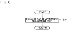
- FIG. 6 is a flow chart showing a schematic process of a method of controlling the thermal power generation system 1 according to an embodiment of the present invention.
- the control method of the thermal power generation system 1 includes an exhaust gas temperature adjustment step S10. Then, in the exhaust gas temperature adjustment step S10, the temperature of exhaust gas at the catalyst device 17 is adjusted by adjusting heating of water by the at least one high-pressure feed water heater 15.
- heating of water by the high-pressure feed water heater 15 is adjusted so that the temperature of exhaust gas at the catalyst device 17 becomes not lower than 290°C and not higher than 420°C.
- heating of water by the high-pressure feed water heater 15 is adjusted so that the temperature of exhaust gas at the catalyst device 17 becomes not lower than 320°C and not higher than 400°C.
- heating of water by the high-pressure feed water heater 15 is adjusted so that the temperature of exhaust gas at the catalyst device 17 becomes not lower than 350°C and not higher than 400°C.
- a bypass duct which brings the upstream side and the downstream side of the economizer 23a into communication may be provided, the bypass duct allowing a part of exhaust gas at the inlet of the economizer 23a to bypass the economizer 23a and merge at the outlet of the economizer 23a to flow to the catalyst device 17, so that the exhaust gas temperature at the catalyst device 17 is controlled to be in the above described temperature range, when the exhaust gas temperature itself is low during startup of the boiler 3 or during part load (low load) of the boiler 3 of 50% or less.
- the thermal power generation system 1 may further include a deaerator 57 for removing gas contained in water.
- the deaerator 57 is positioned between the low-pressure feed water heater 11 and the high-pressure feed water pump 13, and is interposed in the feed water path 27. Further, a part (steam S7) of steam discharged from the intermediate-pressure turbine 5b may be supplied to the deaerator 57.
- the thermal power generation system 1 may further include a condensate pump 59 for pumping water condensed by the condenser 9 to the low-pressure feed water heater 11.
- the condensate pump 59 may be positioned between the low-pressure feed water heater 11 and the high-pressure feed water pump 13, and interposed in the feed water path 27.
- the thermal power generation system 1 may include an air heater 61 for heating air to be supplied to the boiler 3.
- the air heater 61 is positioned between the catalyst device 17 and the mercuric oxide removing device 19 and disposed in the exhaust path 29, and is capable of heating air to be supplied to the boiler 3 with a blower 63 through heat exchange with exhaust gas.
- the thermal power generation system 1 is a coal thermal power generation system configured to burn coal as a fuel.
- the fuel is not limited to coal, and may be heavy oil or the like.
Landscapes
- Engineering & Computer Science (AREA)
- Chemical & Material Sciences (AREA)
- Mechanical Engineering (AREA)
- General Engineering & Computer Science (AREA)
- Combustion & Propulsion (AREA)
- Environmental & Geological Engineering (AREA)
- Health & Medical Sciences (AREA)
- Thermal Sciences (AREA)
- Physics & Mathematics (AREA)
- Biomedical Technology (AREA)
- Analytical Chemistry (AREA)
- General Chemical & Material Sciences (AREA)
- Oil, Petroleum & Natural Gas (AREA)
- Chemical Kinetics & Catalysis (AREA)
- Chimneys And Flues (AREA)
- Exhaust Gas Treatment By Means Of Catalyst (AREA)
- Treating Waste Gases (AREA)
- Catalysts (AREA)
Abstract
Description
- The present disclosure relates to a thermal power generation system and a method of controlling the same.
- In recent years, techniques have been developed to reduce mercury concentration of exhaust gas discharged from a thermal power generation system.
- For instance,
Patent Document 1 discloses an exhaust-gas treatment apparatus including a cooling device disposed upstream of a denitration catalyst and configured to control the temperature of exhaust gas to a predetermined temperature of 300 to 400°C. Furthermore, exhaust gas controlled by a cooling device to have a predetermined temperature is guided to the denitration catalyst to reduce and remove nitrogen oxide in the exhaust gas, while metallic mercury in the exhaust gas is caused to react with hydrogen chloride to produce mercury chloride. A desulfurization apparatus disposed downstream of the denitration catalyst removes the mercury chloride from exhaust gas, by dissolving the mercury chloride into an absorbing solution. Accordingly, with the exhaust gas treatment device disclosed inPatent Document 1, it is possible to improve the efficiency of removing mercury from exhaust gas. - Patent Document 1:
JP2007-167698A - As disclosed in
Patent Document 1, if the cooling device is disposed upstream of the denitration catalyst, it is possible to improve the efficiency of removing mercury from exhaust gas, but the configuration of the thermal power generation system becomes complex. Further, as the configuration of the thermal power generation system becomes complex, the efficiency of the entire system may deteriorate. - In view of the above, an object of at least one embodiment of the present invention is to provide a thermal power generation system and a method of controlling a thermal power generation system, whereby it is possible to adjust the temperature of exhaust gas at a catalyst device and remove metallic mercury from exhaust gas efficiently, with a simple configuration.
-
- (1) A thermal power generation system according to at least one embodiment of the present invention includes: a boiler including at least one internal heat exchanger being disposed in a circulation passage through which water is circulatable, and being capable of generating steam through heat exchange between the water and exhaust gas produced by burning fuel; at least one steam turbine being disposed in the circulation passage and being capable of outputting power by utilizing the steam; a generator capable of generating electric power by utilizing the power outputted from the steam turbine; a condenser capable of condensing the steam discharged from the steam turbine; at least one low-pressure feed water heater being disposed in a feed water path forming a part of the circulation passage, extending from the condenser to the at least one internal heat exchanger, and being capable of heating the water condensed by the condenser by utilizing steam extracted from the at least one steam turbine; a high-pressure feed water pump being disposed in the feed water path of the circulation passage so as to be positioned downstream of the at least one low-pressure feed water heater, and being capable of increasing a pressure of the water heated by the at least one low-pressure feed water heater and pumping the water; at least one high-pressure feed water heater being disposed in the feed water path of the circulation passage so as to be positioned between the high-pressure feed water pump and the at least one internal heat exchanger, and being capable of heating the water pumped by the high-pressure feed water pump by utilizing steam extracted from the at least one steam turbine; a catalyst device being disposed in an exhaust path of the exhaust gas extending from the boiler, and including at least one kind of catalyst capable of promoting reduction reaction of nitrogen oxide and oxidation reaction of metallic mercury, the nitrogen oxide and the metallic mercury both being contained in the exhaust gas; at least one mercuric oxide removing device being disposed in the exhaust path so as to be positioned downstream of the catalyst device, and being capable of removing mercuric oxide produced by the oxidation reaction of the metallic mercury from the exhaust gas; and an exhaust gas temperature adjustment device capable of adjusting a temperature of the exhaust gas at the catalyst device, by adjusting heating of the water by the at least one high-pressure feed water heater.
- With the above configuration (1), the exhaust gas temperature adjustment device is capable of adjusting the temperature of exhaust gas at the catalyst device by adjusting heating of water by the at least one high-pressure feed water heater. Thus, in the above configuration (1), it is possible to adjust the temperature of exhaust gas at the catalyst device, and remove metallic mercury from exhaust gas efficiently, with a simplified configuration.
- (2) In some embodiments, in the above configuration (1), the exhaust gas temperature adjustment device includes: an exhaust gas temperature sensor capable of measuring the temperature of the exhaust gas at the catalyst device; at least one bypass passage disposed parallel to the feed water path so as to be capable of bypassing at least one of the at least one high-pressure feed water heater; at least one bypass valve capable of adjusting a flow rate of the water in the at least one bypass passage; and a control device configured to adjust an opening degree of the at least one bypass valve on the basis of a measurement result of the exhaust gas temperature sensor.
- With the above configuration (2), the exhaust gas temperature adjustment device adjusts the opening degree of the at least one bypass valve on the basis of the measurement result of the exhaust gas temperature sensor, and thereby it is possible to adjust the temperature of exhaust gas at the catalyst device appropriately, and remove metallic mercury from exhaust gas efficiently.
- (3) In some embodiments, in the above configuration (1) or (2), the exhaust gas temperature adjustment device includes: an exhaust gas temperature sensor capable of measuring the temperature of the exhaust gas at the catalyst device; at least one extraction valve disposed in at least one extraction passage extending between the at least one steam turbine and the at least one high-pressure feed water heater, and being capable of adjusting a flow rate of steam extracted from the at least one steam turbine; and a control device configured to adjust an opening degree of the at least one extraction valve on the basis of a measurement result of the exhaust gas temperature sensor.
- With the above configuration (3), the exhaust gas temperature adjustment device adjusts the opening degree of the extraction valve on the basis of the measurement result of the exhaust gas temperature sensor, and thereby it is possible to adjust the temperature of exhaust gas at the catalyst device appropriately, and remove metallic mercury from exhaust gas efficiently.
- (4) In some embodiments, in any one of the above configurations (1) to (3), the fuel is lignite, and the exhaust gas temperature adjustment device is configured to adjust the temperature of the exhaust gas at the catalyst device to be not higher than 420°C, or more preferably, not higher than 400°C.
- Of the thermal power generation system, particularly in a coal burning thermal power generation system that uses lignite, dirt mainly composed of oxides of alkali metal and alkali earths abundantly contained in lignite adheres to the surface of the internal heat exchanger of the boiler, and the heat exchange rate at the internal heat exchanger of the boiler tends to decrease with time, which leads to a gradual increase in the exhaust gas temperature. Thus, in a coal burning thermal power generation system using lignite, the temperature of exhaust gas at the catalyst device exceeds 420°C as the operation time advances. The chemical equilibrium between metallic mercury and mercuric oxide has temperature dependency. If the temperature of exhaust gas exceeds 420°C, the chemical equilibrium changes and the proportion of metallic mercury to the entire mercury increases. Furthermore, metallic mercury has a higher vapor pressure than that of mercuric oxide. An increase in the proportion of metallic mercury leads to deterioration of the efficiency of removing mercury from exhaust gas.
- In this regard, with the above configuration (4), the exhaust gas temperature adjustment device is configured to adjust the temperature of exhaust gas at the catalyst device to 420°C or below, and thus it is possible to maintain the chemical equilibrium between metallic mercury and mercuric oxide in a state where the proportion of metallic mercury is relatively small, which makes it possible to remove mercury from exhaust gas reliably and efficiently.
- (5) In some embodiments, in any one of the above configurations (1) to (4), the exhaust gas temperature adjustment device is configured to adjust the temperature of the exhaust gas at the catalyst device to be not lower than 290°C, or more preferably, not lower than 320°C.
- The reduction reaction of nitrogen oxide proceeds smoothly when the temperature of exhaust gas at the catalyst device is 290°C or higher, or more preferably, 320°C or higher. In contrast, if the temperature of exhaust gas is lower than 320°C, depending on the concentration of SOx in exhaust gas or concentration of NH3 injected to achieve the necessary denitration function, acidic ammonium sulfate may be deposited on the catalyst, which may lead to reduction of the activity of the catalyst. When the activity of the catalyst becomes lower, the oxidization reaction of mercury may fail to proceed smoothly.
- In this regard, with the above configuration (5), the exhaust gas temperature adjustment device is configured to adjust the temperature of exhaust gas at the catalyst device to 290°C or higher, or preferably, 320°C or higher, and thus it is possible to remove nitrogen oxide from exhaust gas reliably and efficiently, and remove metallic mercury from exhaust gas reliably and efficiently.
- (6) In some embodiments, in any one of the above configurations (1) to (5), the thermal power generation system further includes an oxidizing agent supply device capable of supplying halogen to be used in the oxidation reaction of the metallic mercury to the catalyst device.
- With the above configuration (6), even if the concentration of hydrogen chloride in exhaust gas is low, by supplying halogen to the catalyst device with the oxidizing agent supply device, it is possible to react the metallic mercury with the halogen to produce mercuric oxide, and remove mercury from exhaust gas reliably and efficiently.
- (7) A method of controlling a thermal power generation system according to at least one embodiment of the present invention is for a thermal power generation system which includes: a boiler including at least one internal heat exchanger being disposed in a circulation passage through which water is circulatable, and being capable of generating steam through heat exchange between the water and exhaust gas produced by burning fuel; at least one steam turbine being disposed in the circulation passage and being capable of outputting power by utilizing the steam; a generator capable of generating electric power by utilizing the power outputted from the steam turbine; a condenser capable of condensing the steam discharged from the steam turbine; at least one low-pressure feed water heater being disposed in a feed water path forming a part of the circulation passage, extending from the condenser to the at least one internal heat exchanger, and being capable of heating the water condensed by the condenser by utilizing steam extracted from the at least one steam turbine; a high-pressure feed water pump being disposed in the feed water path of the circulation passage so as to be positioned downstream of the at least one low-pressure feed water heater, and being capable of increasing a pressure of the water heated by the at least one low-pressure feed water heater and pumping the water; at least one high-pressure feed water heater being disposed in the feed water path of the circulation passage so as to be positioned between the high-pressure feed water pump and the at least one internal heat exchanger, and being capable of heating the water pumped by the high-pressure feed water pump by utilizing steam extracted by the at least one steam turbine; a catalyst device being disposed in an exhaust path of the exhaust gas extending from the boiler, and including at least one kind of catalyst capable of promoting reduction reaction of nitrogen oxide and oxidation reaction of metallic mercury, the nitrogen oxide and the metallic mercury both being contained in the exhaust gas; and at least one mercuric oxide removing device being disposed in the exhaust path so as to be positioned downstream of the catalyst device, and being capable of removing mercuric oxide produced by the oxidation reaction of the metallic mercury from the exhaust gas, and the method includes: a step of adjusting a temperature of the exhaust gas at the catalyst device, by adjusting heating of the water by the at least one high-pressure feed water heater.
- With the above configuration (7), in the exhaust gas temperature adjustment step, it is possible to adjust the temperature of exhaust gas at the catalyst device by adjusting heating of water by the at least one high-pressure feed water heater. Thus, with the above configuration (7), it is possible to adjust the temperature of exhaust gas at the catalyst device, and remove metallic mercury from exhaust gas efficiently, with a simplified configuration.
- According to at least one embodiment of the present invention, it is possible to provide a thermal power generation system and a method of controlling a thermal power generation system, capable of adjusting the temperature of exhaust gas with a catalyst device and removing metallic mercury from exhaust gas efficiently, with a simplified configuration.
-
-
FIG. 1 is a schematic diagram of a thermal power generation system according to an embodiment of the present invention. -
FIG. 2 is a schematic partial diagram of a configuration of a thermal power generation system according to another embodiment of the present invention. -
FIG. 3 is a schematic partial diagram of a configuration of a thermal power generation system according to yet another embodiment of the present invention. -
FIG. 4 is a schematic partial diagram of a configuration of a thermal power generation system according to yet another embodiment of the present invention. -
FIG. 5 is a schematic partial diagram of a configuration of a thermal power generation system according to yet another embodiment of the present invention. -
FIG. 6 is a schematic flow diagram of a method of controlling a thermal power generation system according to an embodiment of the present invention. - Embodiments of the present invention will now be described in detail with reference to the accompanying drawings. It is intended, however, that unless particularly identified, dimensions, materials, shapes, relative positions and the like of components described in the embodiments shall be interpreted as illustrative only and not intended to limit the scope of the present invention.
- For instance, an expression of relative or absolute arrangement such as "in a direction", "along a direction", "parallel", "orthogonal", "centered", "concentric" and "coaxial" shall not be construed as indicating only the arrangement in a strict literal sense, but also includes a state where the arrangement is relatively displaced by a tolerance, or by an angle or a distance whereby it is possible to achieve the same function.
- For instance, an expression of an equal state such as "same" "equal" and "uniform" shall not be construed as indicating only the state in which the feature is strictly equal, but also includes a state in which there is a tolerance or a difference that can still achieve the same function.
- Further, for instance, an expression of a shape such as a rectangular shape or a cylindrical shape shall not be construed as only the geometrically strict shape, but also includes a shape with unevenness or chamfered corners within the range in which the same effect can be achieved.
- On the other hand, an expression such as "comprise", "include", "have", "contain" and "constitute" are not intended to be exclusive of other components.
-
FIG. 1 is a schematic diagram of a thermalpower generation system 1A according to an embodiment of the present invention.FIG. 2 is a schematic partial diagram of a configuration of a thermalpower generation system 1B according to another embodiment of the present invention.FIG. 3 is a schematic partial diagram of a configuration of a thermalpower generation system 1C according to yet another embodiment of the present invention.FIG. 4 is a schematic partial diagram of a configuration of a thermalpower generation system 1D according to yet another embodiment of the present invention.FIG. 5 is a schematic partial diagram of a configuration of a thermalpower generation system 1E according to yet another embodiment of the present invention. - In the following description, thermal
power generation systems 1A to 1E may be referred to as a thermalpower generation system 1, collectively. - As shown in
FIG. 1 , the thermalpower generation system 1 includes aboiler 3, at least onesteam turbine 5, agenerator 7, acondenser 9, at least one low-pressurefeed water heater 11, a high-pressurefeed water pump 13, at least one high-pressurefeed water heater 15, acatalyst device 17, a mercuricoxide removing device 19, and an exhaust gastemperature adjustment device 21. - The
boiler 3 is capable of producing high-temperature combustion gas (exhaust gas) by combusting fuel such as coal by utilizing air. Theboiler 3 includes at least oneinternal heat exchanger 23, which is disposed in acirculation passage 25 through which water can circulate. The at least oneinternal heat exchanger 23 is capable of exchanging heat between exhaust gas and water, and of producing steam through heat exchange between water and exhaust gas produced by combusting fuel. For instance, as shown inFIG. 1 , the at least oneinternal heat exchanger 23 includes aneconomizer 23a, an evaporator (evaporating tube) 23b, a super-heater 23c, and a re-heater 23d. Theeconomizer 23a, the evaporator 23b, the super-heater 23c, and the re-heater 23d are disposed in thecirculation passage 25 in the flow direction of water (circulation direction). - At least one
steam turbine 5 is disposed in thecirculation passage 25, and is capable of outputting power by utilizing steam. For instance, as shown inFIG. 1 , the at least onesteam turbine 5 includes a high-pressure turbine 5a, an intermediate-pressure turbine 5b, and a low-pressure turbine 5c. The high-pressure turbine 5a, the intermediate-pressure turbine 5b, and the low-pressure turbine 5c are disposed in thecirculation passage 25 in this order in the flow direction of water (circulation direction). The high-pressure turbine 5a is disposed downstream of the super-heater 23c. The re-heater 23d is disposed between the high-pressure turbine 5a and the intermediate-pressure turbine 5b. - The
generator 7 is coupled to the at least onesteam turbine 5, and is capable of generating electric power by utilizing power outputted from thesteam turbine 5. - The
condenser 9 is capable of condensing steam discharged from the at least onesteam turbine 5. - The at least one low-pressure
feed water heater 11 is disposed in afeed water path 27 forming a part of thecirculation passage 25. Thefeed water path 27 extends between thecondenser 9 and the at least oneinternal heat exchanger 23, and is for supplying liquid-phase water to theinternal heat exchanger 23. - The at least one low-pressure
feed water heater 11 is capable of heating water condensed by thecondenser 9, by utilizing steam extracted from thesteam turbine 5. The number of low-pressurefeed water heater 11 is not particularly limited. For instance, as shown inFIG. 1 , the low-pressurefeed water heater 11 may include the first low-pressurefeed water heater 11a, the second low-pressurefeed water heater 11b, and the third low-pressurefeed water heater 11c. The first low-pressurefeed water heater 11a, the second low-pressurefeed water heater 11b, and the third low-pressurefeed water heater 11c may be supplied with steam S1, S2, S3, respectively, extracted from the low-pressure turbine 5c, for instance. For instance, the at least one low-pressurefeed water heater 11 is a mixing type feed water heater, in which water flowing through thefeed water path 27 and steam supplied to heat water are mixed. - The high-pressure
feed water pump 13 is disposed in thefeed water path 27 of thecirculation passage 25, and is positioned downstream of the low-pressurefeed water heater 11 in the flow direction of water (circulation direction). The high-pressurefeed water pump 13 is capable of increasing the pressure of water heated by the low-pressurefeed water heater 11 to pump the water. - The at least one high-pressure
feed water heater 15 is disposed in thefeed water path 27 of thecirculation passage 25, and is positioned between the high-pressurefeed water pump 13 and the at least oneinternal heat exchanger 23. The high-pressurefeed water heater 15 is capable of heating water pumped by the high-pressurefeed water pump 13, by utilizing steam extracted from the at least onesteam turbine 5. The number of high-pressurefeed water heater 15 is not particularly limited. For instance, as shown inFIG. 1 , the high-pressurefeed water heater 15 may include the first high-pressurefeed water heater 15a, the second high-pressurefeed water heater 15b, and the third high-pressurefeed water heater 15c. The first high-pressurefeed water heater 15a, the second high-pressurefeed water heater 15b, and the third high-pressurefeed water heater 15c may be supplied with steam S4, S5, S6, respectively, extracted from the high-pressure turbine 5a, for instance. For instance, the at least one high-pressurefeed water heater 15 is a surface-type feed water heater, in which water flowing through thefeed water path 27 and steam supplied to heat water are not mixed. - The
catalyst device 17 is disposed in theexhaust path 29 of exhaust gas extending from theboiler 3. As shown inFIG.1 , for instance, thecatalyst device 17 includes a denitration device (selective catalytic reduction device; SCR) 31. - The
exhaust path 29 is a path for discharging exhaust gas after heat exchange with the at least oneinternal heat exchanger 23 of theboiler 3. The exhaust gas after heat exchange with the at least oneinternal heat exchanger 23 contains nitrogen oxide and metallic mercury. - The
catalyst device 17 includes at least one kind of catalyst. The at least one kind of catalyst is capable of promoting reduction reaction of nitrogen oxide and oxidation reaction of metallic mercury, each contained in exhaust gas. - Although not shown, the at least one kind of catalyst is supported by a carrier.
- The catalyst is not particularly limited as long as it is capable of promoting reduction reaction of nitrogen oxide and oxidation reaction of metallic mercury. For example, it is possible to use, as a catalyst, a metallic oxide of V (vanadium), W (tungsten), Mo (molybdenum), Ni (nickel), Co (cobalt), Fe (iron), Cr (chromium), Mn (manganese), Cu (copper) or the like, or sulfate, or a noble metal such as Pt (platinum), Ru (ruthenium), Rh (rhodium), Pd (palladium), Ir (iridium), or the like, a mixture thereof can be used. Furthermore, for example, as a carrier, titania, silica, zirconia and a composite oxide thereof, or zeolite can be used.
- Further, for example, as a catalyst, a composition containing an oxide of Ti (titanium), Mo and/or W, V, and Bi (bismuth) and having an atomic ratio Ti: (Mo+W): V = 75-98.9 : 1-15 : 0.1-10, and an atomic ratio B / (Mo + W) = 0.1-0.8 can be used.
- Furthermore, for example, as a catalyst, a composition containing an oxide of each of Ti, Mo and/or W, V and P (phosphorus) and having an atomic ratio Ti: (Mo+W): V = 85-97.5 : 2-10 : 0.5-10, and an atomic ratio P / (Mo+W+V) = 0.5-1.5 can be used.
- Furthermore, for example, as a catalyst, a catalyst containing titanium oxide as a main component, and an oxide of at least one kind of element selected from the group consisting of W, Mo and V as an active component, and further containing phosphoric acid or a water-soluble phosphoric acid compound so that the atomic ratio of phosphorus to the active component is greater than zero and not greater than 1.0 can be used. In this catalyst, the following expression is satisfied: 0 < P/active component (atomic ratio) = P mole number/(W mole number+Mo mole number+V mole number) ≤ 1.0.
- Further, for example, as a catalyst, a catalyst containing titanium oxide being in contact with phosphoric acid or ammonium phosphate salt in an amount of more than 1 and not more than 15 weight% with respect to titanium oxide in the presence of water, the titanium oxide having phosphate ions adsorbed to the surface of the titanium oxide and supporting an oxo acid or oxo acid salt of Mo and/or W and an oxo acid salt or vanadyl salt of V in an amount of more than 0 and not more than 8 atom% can be used. Further, for example, as a catalyst, a catalyst containing TiO2 as a carrier, supporting V2O5 and MoO3 on the carrier as active components, and supporting at least one type of element of compound selected from the group consisting of W, Cu, Co, Ni, and Zn (zinc), and compounds thereof can be used.
- The at least one mercuric
oxide removing device 19 is positioned downstream of thecatalyst device 17 and disposed in theexhaust path 29, and is capable of removing mercuric oxide produced by oxidation reaction of metallic mercury from exhaust gas. For instance, as shown inFIG .1 , the mercuricoxide removing device 19 includes adust collector 33 and a wet-type desulfurization apparatus 35. Thedust collector 33 removes mercuric oxide from exhaust gas, along with ash. In thedesulfurization apparatus 35, mercuric oxide dissolves into an absorbing solution, thus the mercuric oxide is removed from exhaust gas. Theexhaust path 29 extends to astack 36 arranged downstream of thedesulfurization apparatus 35, and exhaust gas deprived of mercury is released from thestack 36 into atmosphere. - Then, in the thermal
power generation system 1, the exhaust gastemperature adjustment device 21 is capable of adjusting the temperature of exhaust gas at thecatalyst device 17 by adjusting heating of water by the at least one high-pressurefeed water heater 15. - With the thermal
power generation system 1 having the above configuration, the exhaust gastemperature adjustment device 21 is capable of adjusting the temperature of exhaust gas at thecatalyst device 17 by adjusting heating of water by the at least one high-pressurefeed water heater 15. Thus, in the above configuration, it is possible to adjust the temperature of exhaust gas at thecatalyst device 17, and remove metallic mercury from exhaust gas efficiently, with a simplified configuration. - In some embodiments, as shown in
FIGs. 1 to 5 , the exhaust gastemperature adjustment device 21 includes an exhaustgas temperature sensor 37, at least onebypass passage 39, at least onebypass valve 41, and acontrol device 43. - The exhaust
gas temperature sensor 37 is capable of measuring the temperature of exhaust gas of thecatalyst device 17. As long as the exhaustgas temperature sensor 37 is capable of measuring the temperature of exhaust gas of thecatalyst device 17, the exhaustgas temperature sensor 37 may be positioned upstream or downstream of thecatalyst device 17 in the flow direction of exhaust gas. - The at least one
bypass passage 39 is disposed in parallel to thefeed water path 27 so as to be capable of bypassing at least one of the at least one high-pressurefeed water heater 15. - The at least one
bypass valve 41 is capable of adjusting the flow rate of water in the at least onebypass passage 39. - The
control device 43 includes a computer, for instance, and is configured to adjust the opening degree of the at least onebypass valve 41 on the basis of the measurement result of the exhaustgas temperature sensor 37. - According to the thermal
power generation system 1 having the above configuration, thecontrol device 43 of the exhaust gastemperature adjustment device 21 is capable of adjusting the opening degree of the at least onebypass valve 41 on the basis of the measurement result of the exhaustgas temperature sensor 37. Thus, with a simplified configuration, it is possible to adjust the temperature of exhaust gas at thecatalyst device 17 appropriately, and remove metallic mercury from exhaust gas efficiently. - As the flow rate of water flowing through the
bypass passage 39 increases, the temperature of water supplied to theinternal heat exchanger 23 decreases, and it is possible to decrease the temperature of exhaust gas at thecatalyst device 17. On the other hand, as the flow rate of water flowing through thebypass passage 39 decreases, the temperature of water supplied to theinternal heat exchanger 23 increases, and it is possible to increase the temperature of exhaust gas at thecatalyst device 17. - In some embodiments, as shown in
FIGs. 1 ,2 ,3 and5 , thebypass passage 39 is disposed so as to bypass all of the plurality of high-pressurefeed water heaters bypass valve 41 includes two three-way valves bypass passage 39 and thefeed water path 27. - With the above configuration, as the
control device 43 switches the three-way valves feed water path 27 can flow through all of the plurality of high-pressurefeed water heaters feed water heaters - In some embodiments, as shown in
FIG. 4 , thebypass passage 39 includes afirst bypass passage 39a capable of bypassing the first high-pressurefeed water heater 15a, asecond bypass passage 39b capable of bypassing the second high-pressurefeed water heater 15b, and athird bypass passage 39c capable of bypassing the third high-pressurefeed water heater 15c. The downstream side of thefirst bypass passage 39a and the upstream side of thesecond bypass passage 39b may be overlapped. The downstream side of thesecond bypass passage 39b and the upstream side of thethird bypass passage 39c may be overlapped. - Further, the at least one
bypass valve 41 includes four three-way valves feed water path 27 and each of thefirst bypass passage 39a, thesecond bypass passage 39b, and thethird bypass passage 39c. - With the above configuration, as the
control device 43 switches the three-way valves feed water path 27 can flow through all or a part of the plurality of high-pressurefeed water heaters feed water heaters feed water path 27 to flow through only a part of the plurality of high-pressurefeed water heaters internal heat exchanger 23. As a result, it is possible to adjust the temperature of exhaust gas at thecatalyst device 17 appropriately, and remove metallic mercury from exhaust gas efficiently. - In some embodiments, as shown in
FIGs. 2, 3 , and4 , the exhaust gastemperature adjustment device 21 includes an exhaustgas temperature sensor 37, at least oneextraction valve 45, and acontrol device 43. - The exhaust
gas temperature sensor 37 is the same as the one described in the above embodiment. - The at least one
extraction valve 45 is capable of adjusting the flow rate of steam extracted from the at least onesteam turbine 5 in the at least oneextraction passage 47 extending between the at least onesteam turbine 5 and the at least one high-pressurefeed water heater 15. - For instance, as shown in
FIGs. 2, 3 , and4 , the at least oneextraction passage 47 includes thefirst extraction passage 47a, thesecond extraction passage 47b, and thethird extraction passage 47c, extending between the high-pressure turbine 5a and the first high-pressurefeed water heater 15a, the second high-pressurefeed water heater 15b, and the third high-pressurefeed water heater 15c, respectively. - Further, the at least one
extraction valve 45 includes thefirst extraction valve 45a, thesecond extraction valve 45b, and thethird extraction valve 45c, disposed in thefirst extraction passage 47a, thesecond extraction passage 47b, and thethird extraction passage 47c, respectively. Thefirst extraction valve 45a, thesecond extraction valve 45b, and thethird extraction valve 45c are capable of adjusting the flow rate of the steam S4, S5, S6 of corresponding one of thefirst extraction passage 47a, thesecond extraction passage 47b, and thethird extraction passage 47c, respectively. - The
control device 43 includes a computer, for instance, and is configured to adjust the opening degree of the at least oneextraction valve 45 on the basis of the measurement result of the exhaustgas temperature sensor 37. For instance, thecontrol device 43 is capable of adjusting the flow rate of steam supplied to at least one of the first high-pressurefeed water heater 15a, the second high-pressurefeed water heater 15b, or the third high-pressurefeed water heater 15c, by adjusting at least one of thefirst extraction valve 45a, thesecond extraction valve 45b, or thethird extraction valve 45c. - Thus, with the above configuration, the exhaust gas
temperature adjustment device 21 adjusts the opening degree of theextraction valve 45 on the basis of the measurement result of the exhaustgas temperature sensor 37, and thereby it is possible to adjust the temperature of exhaust gas at thecatalyst device 17 appropriately, and remove metallic mercury from exhaust gas efficiently, with a simplified configuration. - The
control device 43 may be configured to adjust the opening degree of both of the at least onebypass valve 41 and the at least one extraction valve on the basis of the measurement result of the exhaustgas temperature sensor 37, or may be configured to adjust the opening degree of either one of the at least onebypass valve 41 or the at least one extraction valve. In a case where thecontrol device 43 is configured to adjust only the opening degree of theextraction valve 45, thebypass passage 39 and thebypass valve 41 may be omitted. - In some embodiments, fuel supplied to the
boiler 3 as fuel is lignite, and the exhaust gastemperature adjustment device 21 is configured to adjust the temperature of exhaust gas at thecatalyst device 17 to be not higher than 420°C, or more preferably, not higher than 400°C. - Of the thermal power generation system, particularly in a coal burning thermal power generation system that uses lignite, the heat exchange rate at the internal heat exchanger of the boiler tends to decrease with time, which leads to a gradual increase in the exhaust gas temperature. Thus, in the coal burning thermal power generation system using lignite, the temperature of exhaust gas at the catalyst device (denitration device) exceeds 420°C as the operation time advances. The chemical equilibrium between metallic mercury and mercuric oxide has temperature dependency. If the temperature of exhaust gas exceeds 420°C, the chemical equilibrium changes and the proportion of metallic mercury to the entire mercury increases. Furthermore, metallic mercury has a higher vapor pressure than that of mercuric oxide. An increase in the proportion of metallic mercury leads to deterioration of the efficiency of removing mercury from exhaust gas.
- In this regard, with the thermal power generation system having the above configuration, the exhaust gas
temperature adjustment device 21 is configured to adjust the temperature of exhaust gas at thecatalyst device 17 to 420°C or below, and thus it is possible to maintain the chemical equilibrium between metallic mercury and mercuric oxide in a state where the proportion of metallic mercury is relatively small, which makes it possible to remove mercury from exhaust gas reliably and efficiently. - In some embodiments, the exhaust gas
temperature adjustment device 21 is configured to adjust the temperature of exhaust gas at thecatalyst device 17 to be not higher than 400°C. - With the above configuration, the exhaust gas
temperature adjustment device 21 is configured to adjust the temperature of exhaust gas at thecatalyst device 17 to 400°C or below, and thus it is possible to maintain the chemical equilibrium between metallic mercury and mercuric oxide in a state where the proportion of metallic mercury is relatively small, and to remove mercury from exhaust gas reliably and efficiently. - In some embodiments, the exhaust gas
temperature adjustment device 21 is configured to adjust the temperature of exhaust gas at thecatalyst device 17 to be not lower than 290°C, or more preferably, not lower than 320°C. - The reduction reaction of nitrogen oxide proceeds smoothly when the temperature of exhaust gas at the
catalyst device 17 is 290°C or higher, or more preferably, 320°C or higher. In contrast, if the temperature of exhaust gas is lower than 320°C, depending on the concentration of SOx in exhaust gas or concentration of NH3 injected to achieve the necessary denitration function, acidic ammonium sulfate may be deposited on the catalyst, which may cause reduction of the activity of the catalyst. When the activity of the catalyst decreases, the oxidization reaction of mercury may fail to proceed smoothly. - In this regard, with the thermal
power generation system 1 having the above configuration, the exhaust gastemperature adjustment device 21 is configured to adjust the temperature of exhaust gas at thecatalyst device 17 to 290°C or higher, or preferably, 320°C or higher, and thus it is possible to remove nitrogen oxide from exhaust gas reliably and efficiently, and remove metallic mercury from exhaust gas reliably and efficiently. - In some embodiments, the exhaust gas
temperature adjustment device 21 is configured to adjust the temperature of exhaust gas at thecatalyst device 17 to be not lower than 290°C and not higher than 420°C. - In some embodiments, the exhaust gas
temperature adjustment device 21 is configured to adjust the temperature of exhaust gas at thecatalyst device 17 to be not lower than 320°C and not higher than 420°C. - In some embodiments, the exhaust gas
temperature adjustment device 21 is configured to adjust the temperature of exhaust gas at thecatalyst device 17 to be not lower than 320°C and not higher than 400°C. - With this configuration, by adjusting the temperature of exhaust gas to 400°C or below, it is possible to maintain the chemical equilibrium between metallic mercury and mercuric oxide in a state where the proportion of metallic mercury is relatively even smaller, and to remove mercury from exhaust gas even more reliably and efficiently.
- In some embodiments, the exhaust gas
temperature adjustment device 21 is configured to adjust the temperature of exhaust gas at thecatalyst device 17 to be not lower than 350°C and not higher than 400°C. - With this configuration, by adjusting the temperature of exhaust gas to 350°C or higher, it is possible to suppress deposition of acidic ammonium sulfate even more reliably, and remove nitrogen oxide from exhaust gas reliably and efficiently, while removing metallic mercury from exhaust gas reliably and efficiently.
- In some embodiments, the exhaust gas
temperature adjustment device 21 is configured to adjust the temperature of exhaust gas at thecatalyst device 17 to be not lower than 290°C and not higher than 420°C, if the load factor of theboiler 3 is not smaller than 50% and not greater than 100%. - If the load factor of the
boiler 3 is not smaller than 50% and not greater than 100%, the temperature of exhaust gas at thecatalyst device 17 is likely to become high. In this regard, with the above configuration, even if the load factor of theboiler 3 is not smaller than 50% and not greater than 100%, the temperature of exhaust gas at thecatalyst device 17 can be adjusted to be not lower than 290°C and not higher than 420°C. - In some embodiments, the exhaust gas
temperature adjustment device 21 is configured to adjust the temperature of exhaust gas at thecatalyst device 17 to be not lower than 320°C and not higher than 400°C, if the load factor of theboiler 3 is not smaller than 50% and not greater than 100%. - In some embodiments, the exhaust gas
temperature adjustment device 21 is configured to adjust the temperature of exhaust gas at thecatalyst device 17 to be not lower than 350°C and not higher than 400°C, if the load factor of theboiler 3 is not smaller than 50% and not greater than 100%. - In some embodiments, the exhaust gas
temperature adjustment device 21 is configured to adjust the temperature of exhaust gas at thecatalyst device 17 to be not lower than 290°C and not higher than 420°C, if the load factor of theboiler 3 is not smaller than 25% and not greater than 50%. - If the load factor of the
boiler 3 is not smaller than 25% and not greater than 50%, the temperature of exhaust gas at thecatalyst device 17 is likely to become low. In this regard, with the above configuration, even if the load factor of theboiler 3 is not smaller than 25% and not greater than 50%, the temperature of exhaust gas at thecatalyst device 17 can be adjusted to be not lower than 290°C and not higher than 420°C. - In some embodiments, the exhaust gas
temperature adjustment device 21 is configured to adjust the temperature of exhaust gas at thecatalyst device 17 to be not lower than 320°C and not higher than 400°C, if the load factor of theboiler 3 is not smaller than 25% and not greater than 100%. - In some embodiments, the exhaust gas
temperature adjustment device 21 is configured to adjust the temperature of exhaust gas at thecatalyst device 17 to be not lower than 350°C and not higher than 400°C, if the load factor of theboiler 3 is not smaller than 25% and not greater than 100%. - In some embodiments, the exhaust gas
temperature adjustment device 21 is configured such that all of the high-pressurefeed water heaters 15 heat water during startup of theboiler 3. - With the above configuration, during startup of the
boiler 3, water is heater by all of the high-pressurefeed water heaters 15, and thereby it is possible to increase the temperature of water to be supplied to theinternal heat exchanger 23 quickly, and increase the temperature of exhaust gas at thecatalyst device 17 quickly. - In some embodiments, as shown in
FIGs. 3 and4 , the exhaust gastemperature adjustment device 21 includes a feedwater temperature sensor 49 capable of measuring the temperature of water (feed water) to be supplied to the at least oneinternal heat exchanger 23 from the at least one high-pressurefeed water heater 15. Thecontrol device 43 is capable of adjusting the temperature of exhaust gas at thecatalyst device 17 by adjusting heating of water by the at least one high-pressurefeed water heater 15, on the basis of the temperature of exhaust gas at thecatalyst device 17 measured by the exhaustgas temperature sensor 37 and the temperature of feed water to theinternal heat exchanger 23 measured by the feedwater temperature sensor 49. - With the above configuration, the exhaust gas
temperature adjustment device 21 adjusts heating of water by the at least one high-pressurefeed water heater 15 on the basis of, in addition to the temperature of exhaust gas at thecatalyst device 17, the temperature of feed water to theinternal heat exchanger 23 measured by the feedwater temperature sensor 49, and thereby it is possible to adjust the temperature of exhaust gas at thecatalyst device 17 more precisely. - Further, the feed
water temperature sensor 49 is disposed in a section of thefeed water path 27, which extends between theboiler 3 and the high-pressurefeed water heater 15. - In some embodiments, the exhaust gas
temperature adjustment device 21 is configured to adjust the temperature of feed water to theinternal heat exchanger 23 to be not lower than 130°C and not higher than 300°C. - In some embodiments, the exhaust gas
temperature adjustment device 21 is configured to adjust the temperature of exhaust gas at thecatalyst device 17 to be not lower than 290°C and not higher than 420°C, and the temperature of feed water to theinternal heat exchanger 23 to be not lower than 130°C and not higher than 300°C, if the load factor of theboiler 3 is not smaller than 25% and not greater than 50%, and if the load factor of theboiler 3 is not smaller than 50% and not greater than 100%. - In some embodiments, the exhaust gas
temperature adjustment device 21 is configured to adjust the temperature of exhaust gas at thecatalyst device 17 to be not lower than 320°C and not higher than 400°C, and the temperature of feed water to theinternal heat exchanger 23 to be not lower than 130°C and not higher than 300°C, if the load factor of theboiler 3 is not smaller than 25% and not greater than 50%, and if the load factor of theboiler 3 is not smaller than 50% and not greater than 100%. - In some embodiments, the exhaust gas
temperature adjustment device 21 is configured to adjust the temperature of exhaust gas at thecatalyst device 17 to not lower than 350°C and not higher than 400°C, and the temperature of feed water to theinternal heat exchanger 23 to not lower than 130°C and not higher than 300°C, if the load factor of theboiler 3 is not smaller than 25% and not greater than 50%, and not smaller than 50% and not greater than 100%. - In some embodiments, as shown in
FIG. 1 , the thermalpower generation system agent supply device 51. The oxidizingagent supply device 51 is capable of supplying, to thecatalyst device 17, halogen used in oxidation reaction of metallic mercury. - With the above configuration, even if the concentration of hydrogen chloride in exhaust gas is low, by supplying halogen to the
catalyst device 17 with the oxidizingagent supply device 51, it is possible to react the metallic mercury with the halogen to produce mercuric oxide, and remove mercury from exhaust gas reliably and efficiently. - In some embodiments, the oxidizing
agent supply device 51 is configured to be capable of supplying, to the upstream side of thecatalyst device 17, an aqueous solution of ammonium halide, for example ammonium chloride, as an oxidizing agent. - With the above configuration, it is possible to supply ammonium to be used in reduction reaction of nitrogen oxide to the
catalyst device 17 at the same time. - Further, besides ammonium chloride, ammonium bromide and ammonium iodide can be also used as an ammonium halide.
- In some embodiments, as shown in
FIG. 5 , the thermalpower generation system mercury concentration sensor 53 and an oxidizing agent supplyamount regulating valve 55. - The
mercury concentration sensor 53 is, for instance, disposed in theexhaust path 29 and positioned downstream of thecatalyst device 17, being capable of measuring the mercury concentration of exhaust gas. The oxidizing agent supplyamount regulating valve 55 is disposed in the supply passage of oxidizing agent to thecatalyst device 17, and is capable of regulating the flow rate of oxidizing agent to be supplied to thecatalyst device 17. Further, thecontrol device 43 may be used, or another control device may be provided, to enable regulation of the flow rate of oxidizing agent to be supplied to thecatalyst device 17, on the basis of the measurement result of the metallic mercury concentration and oxidized metallic concentration of themercury concentration sensor 53. - With the above configuration, by measuring the mercury concentration and adjusting the supply amount of oxidizing agent on the basis of the measurement result of the metallic mercury concentration and mercuric oxide concentration, it is possible to react the metallic mercury with halogen reliably, and remove mercury from exhaust gas reliably and efficiently.
-
FIG. 6 is a flow chart showing a schematic process of a method of controlling the thermalpower generation system 1 according to an embodiment of the present invention. - As shown in
FIG. 6 , the control method of the thermalpower generation system 1 includes an exhaust gas temperature adjustment step S10. Then, in the exhaust gas temperature adjustment step S10, the temperature of exhaust gas at thecatalyst device 17 is adjusted by adjusting heating of water by the at least one high-pressurefeed water heater 15. - According to the above method of controlling the thermal
power generation system 1 having the above configuration, it is possible to adjust the temperature of exhaust gas at thecatalyst device 17 by adjusting heating of water with the at least one high-pressurefeed water heater 15. Thus, in the above configuration, it is possible to adjust the temperature of exhaust gas at thecatalyst device 17, and remove metallic mercury from exhaust gas efficiently with a simplified configuration. - In some embodiments, in the exhaust gas temperature adjustment step S10, heating of water by the high-pressure
feed water heater 15 is adjusted so that the temperature of exhaust gas at thecatalyst device 17 becomes not lower than 290°C and not higher than 420°C. - In some embodiments, in the exhaust gas temperature adjustment step S10, heating of water by the high-pressure
feed water heater 15 is adjusted so that the temperature of exhaust gas at thecatalyst device 17 becomes not lower than 320°C and not higher than 400°C. - In some embodiments, in the exhaust gas temperature adjustment step S10, heating of water by the high-pressure
feed water heater 15 is adjusted so that the temperature of exhaust gas at thecatalyst device 17 becomes not lower than 350°C and not higher than 400°C. - Embodiments of the present invention were described in detail above, but the present invention is not limited thereto, and various amendments and modifications may be implemented.
- For instance, as a modification, a bypass duct which brings the upstream side and the downstream side of the
economizer 23a into communication may be provided, the bypass duct allowing a part of exhaust gas at the inlet of theeconomizer 23a to bypass theeconomizer 23a and merge at the outlet of theeconomizer 23a to flow to thecatalyst device 17, so that the exhaust gas temperature at thecatalyst device 17 is controlled to be in the above described temperature range, when the exhaust gas temperature itself is low during startup of theboiler 3 or during part load (low load) of theboiler 3 of 50% or less. - Further, for instance, as shown in
FIG. 1 , the thermalpower generation system 1 may further include adeaerator 57 for removing gas contained in water. In this case, thedeaerator 57 is positioned between the low-pressurefeed water heater 11 and the high-pressurefeed water pump 13, and is interposed in thefeed water path 27. Further, a part (steam S7) of steam discharged from the intermediate-pressure turbine 5b may be supplied to thedeaerator 57. - Further, for instance, the thermal
power generation system 1 may further include acondensate pump 59 for pumping water condensed by thecondenser 9 to the low-pressurefeed water heater 11. In this case, thecondensate pump 59 may be positioned between the low-pressurefeed water heater 11 and the high-pressurefeed water pump 13, and interposed in thefeed water path 27. - Furthermore, for instance, the thermal
power generation system 1 may include anair heater 61 for heating air to be supplied to theboiler 3. Theair heater 61 is positioned between thecatalyst device 17 and the mercuricoxide removing device 19 and disposed in theexhaust path 29, and is capable of heating air to be supplied to theboiler 3 with ablower 63 through heat exchange with exhaust gas. - Further, for instance, in the above described embodiment, the thermal
power generation system 1 is a coal thermal power generation system configured to burn coal as a fuel. However, the fuel is not limited to coal, and may be heavy oil or the like. -
- 1A, 1B, 1C, 1D, 1E
- Thermal power generation system
- 3
- Boiler
- 5
- Steam turbine
- 5a
- High-pressure turbine
- 5b
- Intermediate-pressure turbine
- 5c
- Low-pressure turbine
- 7
- Generator
- 9
- Condenser
- 11
- Low-pressure feed water heater
- 11a
- First low-pressure feed water heater
- 11b
- Second low-pressure feed water heater
- 11c
- Third low-pressure feed water heater
- 13
- High-pressure feed water pump
- 15
- High-pressure feed water heater
- 15a
- First high-pressure feed water heater
- 15b
- Second high-pressure feed water heater
- 15c
- Third high-pressure feed water heater
- 17
- Catalyst device
- 19
- Mercuric oxide removing device
- 21
- Exhaust gas temperature adjustment device
- 23
- Internal heat exchanger
- 23a
- Economizer
- 23b
- Evaporator
- 23c
- Super-heater
- 23d
- Re-heater
- 25
- Circulation passage
- 27
- Feed water path
- 29
- Exhaust path
- 31
- Denitration device
- 33
- Dust collector
- 35
- Desulfurization apparatus
- 36
- Stack
- 37
- Exhaust gas temperature sensor
- 39
- Bypass passage
- 39a
- First bypass passage
- 39b
- Second bypass passage
- 39c
- Third bypass passage
- 41
- Bypass valve
- 41a, 41b, 41c, 41d, 41e, 41f
- Three-way valve
- 43
- Control device
- 45
- Extraction valve
- 45a
- First extraction valve
- 45b
- Second extraction valve
- 45c
- Third extraction valve
- 47
- Extraction passage
- 47a
- First extraction passage
- 47b
- Second extraction passage
- 47c
- Third extraction passage
- 49
- Feed water temperature sensor
- 51
- Oxidizing agent supply device
- 53
- Mercury concentration sensor
- 55
- Oxidizing agent supply amount regulating valve
- 57
- Deaerator
- 59
- Condensate pump
- 61
- Air heater
- 63
- Blower
Claims (7)
- A thermal power generation system, comprising:a boiler including at least one internal heat exchanger being disposed in a circulation passage through which water is circulatable, and being capable of generating steam through heat exchange between the water and exhaust gas produced by burning fuel;at least one steam turbine being disposed in the circulation passage and being capable of outputting power by utilizing the steam;a generator capable of generating electric power by utilizing the power outputted from the steam turbine;a condenser capable of condensing the steam discharged from the steam turbine;at least one low-pressure feed water heater being disposed in a feed water path forming a part of the circulation passage, extending from the condenser to the at least one internal heat exchanger, and being capable of heating the water condensed by the condenser by utilizing steam extracted from the at least one steam turbine;a high-pressure feed water pump being disposed in the feed water path of the circulation passage so as to be positioned downstream of the at least one low-pressure feed water heater, and being capable of increasing a pressure of the water heated by the at least one low-pressure feed water heater and pumping the water;at least one high-pressure feed water heater being disposed in the feed water path of the circulation passage so as to be positioned between the high-pressure feed water pump and the at least one internal heat exchanger, and being capable of heating the water pumped by the high-pressure feed water pump by utilizing steam extracted by the at least one steam turbine;a catalyst device being disposed in an exhaust path of the exhaust gas extending from the boiler, and including at least one kind of catalyst capable of promoting reduction reaction of nitrogen oxide and oxidation reaction of metallic mercury, the nitrogen oxide and the metallic mercury both being contained in the exhaust gas;at least one mercuric oxide removing device being disposed in the exhaust path so as to be positioned downstream of the catalyst device, and being capable of removing mercuric oxide produced by the oxidation reaction of the metallic mercury from the exhaust gas; andan exhaust gas temperature adjustment device capable of adjusting a temperature of the exhaust gas at the catalyst device, by adjusting heating of the water by the at least one high-pressure feed water heater.
- The thermal power generation system according to claim 1,
wherein the exhaust gas temperature adjustment device includes:an exhaust gas temperature sensor capable of measuring the temperature of the exhaust gas at the catalyst device;at least one bypass passage disposed parallel to the feed water path so as to be capable of bypassing at least one of the at least one high-pressure feed water heater;at least one bypass valve capable of adjusting a flow rate of the water in the at least one bypass passage; anda control device configured to adjust an opening degree of the at least one bypass valve on the basis of a measurement result of the exhaust gas temperature sensor. - The thermal power generation system according to claim 1 or 2,
wherein the exhaust gas temperature adjustment device includes:an exhaust gas temperature sensor capable of measuring the temperature of the exhaust gas at the catalyst device;at least one extraction valve disposed in at least one extraction passage extending between the at least one steam turbine and the at least one high-pressure feed water heater, and being capable of adjusting a flow rate of steam extracted from the at least one steam turbine; anda control device configured to adjust an opening degree of the at least one extraction valve on the basis of a measurement result of the exhaust gas temperature sensor. - The thermal power generation system according to any one of claims 1 to 3,
wherein the fuel is lignite, and
wherein the exhaust gas temperature adjustment device is configured to adjust the temperature of the exhaust gas at the catalyst device to be not higher than 420°C. - The thermal power generation system according to any one of claims 1 to 4,
wherein the exhaust gas temperature adjustment device is configured to adjust the temperature of the exhaust gas at the catalyst device to be not lower than 290°C. - The thermal power generation system according to any one of claims 1 to 5, further comprising an oxidizing agent supply device capable of supplying halogen to be used in the oxidation reaction of the metallic mercury to the catalyst device.
- A method of controlling a thermal power generation system which comprises:a boiler including at least one internal heat exchanger being disposed in a circulation passage through which water is circulatable, and being capable of generating steam through heat exchange between the water and exhaust gas produced by burning fuel;at least one steam turbine being disposed in the circulation passage and being capable of outputting power by utilizing the steam;a generator capable of generating electric power by utilizing the power outputted from the steam turbine;a condenser capable of condensing the steam discharged from the steam turbine;at least one low-pressure feed water heater being disposed in a feed water path forming a part of the circulation passage, extending from the condenser to the at least one internal heat exchanger, and being capable of heating the water condensed by the condenser by utilizing steam extracted from the at least one steam turbine;a high-pressure feed water pump being disposed in the feed water path of the circulation passage so as to be positioned downstream of the at least one low-pressure feed water heater, and being capable of increasing a pressure of the water heated by the at least one low-pressure feed water heater and pumping the water;at least one high-pressure feed water heater being disposed in the feed water path of the circulation passage so as to be positioned between the high-pressure feed water pump and the at least one internal heat exchanger, and being capable of heating the water pumped by the high-pressure feed water pump by utilizing steam extracted by the at least one steam turbine;a catalyst device being disposed in an exhaust path of the exhaust gas extending from the boiler, and including at least one kind of catalyst capable of promoting reduction reaction of nitrogen oxide and oxidation reaction of metallic mercury, the nitrogen oxide and the metallic mercury both being contained in the exhaust gas; andat least one mercuric oxide removing device being disposed in the exhaust path so as to be positioned downstream of the catalyst device, and being capable of removing mercuric oxide produced by the oxidation reaction of the metallic mercury from the exhaust gas,the method comprising:a step of adjusting a temperature of the exhaust gas at the catalyst device, by adjusting heating of the water by the at least one high-pressure feed water heater.
Priority Applications (1)
| Application Number | Priority Date | Filing Date | Title |
|---|---|---|---|
| PL17769763T PL3434974T3 (en) | 2016-03-25 | 2017-02-21 | Thermal power generation system and control method for same |
Applications Claiming Priority (2)
| Application Number | Priority Date | Filing Date | Title |
|---|---|---|---|
| JP2016061214A JP6737611B2 (en) | 2016-03-25 | 2016-03-25 | Thermal power generation system and method for controlling thermal power generation system |
| PCT/JP2017/006334 WO2017163717A1 (en) | 2016-03-25 | 2017-02-21 | Thermal power generation system and control method for same |
Publications (3)
| Publication Number | Publication Date |
|---|---|
| EP3434974A1 true EP3434974A1 (en) | 2019-01-30 |
| EP3434974A4 EP3434974A4 (en) | 2019-11-13 |
| EP3434974B1 EP3434974B1 (en) | 2021-01-13 |
Family
ID=59901003
Family Applications (1)
| Application Number | Title | Priority Date | Filing Date |
|---|---|---|---|
| EP17769763.8A Not-in-force EP3434974B1 (en) | 2016-03-25 | 2017-02-21 | Thermal power generation system and control method for same |
Country Status (5)
| Country | Link |
|---|---|
| US (1) | US10968783B2 (en) |
| EP (1) | EP3434974B1 (en) |
| JP (1) | JP6737611B2 (en) |
| PL (1) | PL3434974T3 (en) |
| WO (1) | WO2017163717A1 (en) |
Families Citing this family (13)
| Publication number | Priority date | Publication date | Assignee | Title |
|---|---|---|---|---|
| JP6739998B2 (en) * | 2016-05-20 | 2020-08-12 | 三菱日立パワーシステムズ株式会社 | Steam turbine plant |
| JP6891090B2 (en) * | 2017-10-04 | 2021-06-18 | 三菱パワー株式会社 | Power plant and its operation method |
| CN108211693B (en) * | 2017-12-20 | 2020-11-13 | 大唐南京环保科技有限责任公司 | Flat plate type denitration catalyst electric heating device and heating method |
| CN109603530A (en) * | 2019-01-03 | 2019-04-12 | 飞潮(无锡)过滤技术有限公司 | A kind of hot exhaust gas internal circulation compound purification process |
| CN110215768B (en) * | 2019-05-31 | 2021-08-17 | 南京杰科丰环保技术装备研究院有限公司 | A kind of integrated filter material for dust removal, nitrification and mercury removal and preparation method thereof |
| CN110479065A (en) * | 2019-07-22 | 2019-11-22 | 河南禾力能源股份有限公司 | A kind of deslagging smell photooxidation absorption abatement equipment |
| US11702964B2 (en) * | 2020-10-30 | 2023-07-18 | Doosan Enerbility Co., Ltd. | Hybrid power generation equipment and control method thereof |
| WO2022176846A1 (en) * | 2021-02-16 | 2022-08-25 | 三菱重工業株式会社 | Thermal power plant and method for controlling thermal power plant |
| CN113187568B (en) * | 2021-05-28 | 2022-12-20 | 西安热工研究院有限公司 | System and method for reversely improving power supply and heat supply capacity of high-back-pressure heat supply unit |
| CN113404563B (en) * | 2021-06-18 | 2022-08-02 | 东方电气集团东方汽轮机有限公司 | Low-pressure cylinder cutting heat supply unit low-heating and back-heating system |
| US11927344B2 (en) * | 2021-12-23 | 2024-03-12 | General Electric Technology Gmbh | System and method for warmkeeping sub-critical steam generator |
| CN115121101B (en) * | 2022-04-25 | 2023-10-10 | 江苏国信靖江发电有限公司 | A method for adjusting the temperature of the smoke inlet end of the SCR system in thermal power units |
| CN116481011B (en) * | 2023-05-15 | 2025-12-19 | 西安交通大学 | Peak regulating system with fused salt heat storage for coal-fired unit and operation method |
Family Cites Families (20)
| Publication number | Priority date | Publication date | Assignee | Title |
|---|---|---|---|---|
| JP2587445B2 (en) * | 1988-02-01 | 1997-03-05 | 三菱重工業株式会社 | Bleeding control device for bleeding turbine |
| DE10001997A1 (en) * | 2000-01-19 | 2001-07-26 | Alstom Power Schweiz Ag Baden | Composite power plant and method for operating such a composite power plant |
| US7615200B2 (en) * | 2000-12-01 | 2009-11-10 | Fuel Tech, Inc. | Selective catalytic reduction of NOx enabled by urea decomposition in heat-exchanger bypass |
| PT1402153E (en) * | 2001-05-29 | 2013-10-10 | Andritz Oy | Method and arrangement for producing electrical energy at a pulp mill |
| EP1585889A2 (en) * | 2003-01-22 | 2005-10-19 | Vast Power Systems, Inc. | Thermodynamic cycles using thermal diluent |
| JP4981318B2 (en) | 2005-12-19 | 2012-07-18 | 三菱重工業株式会社 | Exhaust gas treatment apparatus and exhaust gas treatment method |
| US8955466B2 (en) * | 2009-02-26 | 2015-02-17 | Doosan Babcock Energy America | Heat recovery system and method |
| US8071036B2 (en) * | 2009-07-06 | 2011-12-06 | Mitsubishi Heavy Industries, Ltd. | Mercury reduction system |
| DE102009036064B4 (en) * | 2009-08-04 | 2012-02-23 | Alstom Technology Ltd. | in order to operate a forced-circulation steam generator operating at a steam temperature of more than 650 ° C, as well as forced circulation steam generators |
| US7931881B2 (en) * | 2009-09-25 | 2011-04-26 | Babcock Power Environmental Inc. | Integrated boiler and air pollution control systems |
| JP5260585B2 (en) * | 2010-03-12 | 2013-08-14 | 株式会社日立製作所 | Coal-fired power plant and method for operating coal-fired power plant |
| US9091182B2 (en) * | 2010-12-20 | 2015-07-28 | Invensys Systems, Inc. | Feedwater heater control system for improved rankine cycle power plant efficiency |
| JP5468562B2 (en) | 2011-02-17 | 2014-04-09 | バブコック日立株式会社 | Coal fired boiler system with carbon dioxide recovery system |
| JP5818307B2 (en) * | 2011-03-14 | 2015-11-18 | 新日鉄住金エンジニアリング株式会社 | Boiler equipment and method for controlling gas temperature at outlet thereof |
| US9488369B2 (en) * | 2012-05-05 | 2016-11-08 | General Electric Technology Gmbh | Enhanced flue gas damper mixing device |
| JP5624646B1 (en) | 2013-05-23 | 2014-11-12 | 電源開発株式会社 | Thermal power plant and operation method of thermal power plant. |
| JP6163994B2 (en) * | 2013-09-18 | 2017-07-19 | 株式会社Ihi | Oxygen combustion boiler exhaust gas cooler steam generation prevention device |
| CN203784915U (en) * | 2014-03-05 | 2014-08-20 | 华电电力科学研究院 | Working temperature control device of SCR (selective catalytic reduction) denitrification reactor of thermal power plant |
| JP2014149148A (en) * | 2014-03-10 | 2014-08-21 | Mitsubishi Heavy Ind Ltd | Mercury removal system and mercury removal method from high-temperature exhaust gas containing mercury |
| EP2942495B1 (en) * | 2014-05-08 | 2018-10-10 | General Electric Technology GmbH | Coal fired oxy plant with heat integration |
-
2016
- 2016-03-25 JP JP2016061214A patent/JP6737611B2/en not_active Expired - Fee Related
-
2017
- 2017-02-21 PL PL17769763T patent/PL3434974T3/en unknown
- 2017-02-21 US US15/776,595 patent/US10968783B2/en not_active Expired - Fee Related
- 2017-02-21 WO PCT/JP2017/006334 patent/WO2017163717A1/en not_active Ceased
- 2017-02-21 EP EP17769763.8A patent/EP3434974B1/en not_active Not-in-force
Also Published As
| Publication number | Publication date |
|---|---|
| JP2017172911A (en) | 2017-09-28 |
| WO2017163717A1 (en) | 2017-09-28 |
| JP6737611B2 (en) | 2020-08-12 |
| PL3434974T3 (en) | 2021-07-05 |
| EP3434974A4 (en) | 2019-11-13 |
| US10968783B2 (en) | 2021-04-06 |
| US20180328231A1 (en) | 2018-11-15 |
| EP3434974B1 (en) | 2021-01-13 |
Similar Documents
| Publication | Publication Date | Title |
|---|---|---|
| EP3434974B1 (en) | Thermal power generation system and control method for same | |
| JP7417013B2 (en) | Exhaust gas treatment method for thermal power plants | |
| RU2543096C1 (en) | METHOD AND DEVICE FOR SELECTIVE CATALYTIC REDUCTION OF NOx IN POWER BOILER | |
| JP4719171B2 (en) | Exhaust gas treatment apparatus and method | |
| US20140010748A1 (en) | SYSTEM USING SELECTIVE CATALYTIC REDUCTION FOR IMPROVING LOW-TEMPERATURE De-NOx EFFICIENCY AND REDUCING YELLOW PLUME | |
| CA1144079A (en) | Apparatus for removing nox and for providing better plant efficiency in combined cycle plants | |
| US8449851B2 (en) | Mercury removing system and mercury removing method | |
| KR101792375B1 (en) | Exhaust gas treatment system and treatment method | |
| US9387436B2 (en) | Exhaust-gas purification device and method for the reduction of nitrogen oxides from an exhaust gas of a fossil-fired power plant | |
| EP3043112B1 (en) | Boiler system and electric power generation plant provided with same | |
| US20110311424A1 (en) | BIOMASS BOILER SCR NOx AND CO REDUCTION SYSTEM | |
| US8475573B2 (en) | System and method for protection of SCR catalyst | |
| WO2015109072A1 (en) | Operating a gas turbine power plant at low load conditions | |
| CN106861674A (en) | A kind of low-temperature SCR flue gas high-efficiency denitration catalyst and preparation method thereof | |
| US9359918B2 (en) | Apparatus for reducing emissions and method of assembly | |
| CN119233941A (en) | Method for cracking ammonia | |
| KR101165646B1 (en) | Energy reducing system of nox reducing apparatus using waste-heat and steam type gas heater | |
| CN205090402U (en) | Denitrification device for smoke gas | |
| JP5386096B2 (en) | Exhaust gas treatment catalyst | |
| JP5945093B2 (en) | Mercury removal equipment | |
| JP6286056B2 (en) | Apparatus and method for operating gas turbine power generation facility under low load condition | |
| JP3014738B2 (en) | Denitration equipment | |
| JP2019030823A (en) | Control method of co oxidation system and co oxidation system | |
| CN118946397A (en) | Waste gas treatment device, combustion equipment and waste gas treatment method | |
| JP2011131196A (en) | Boiler plant |
Legal Events
| Date | Code | Title | Description |
|---|---|---|---|
| STAA | Information on the status of an ep patent application or granted ep patent |
Free format text: STATUS: THE INTERNATIONAL PUBLICATION HAS BEEN MADE |
|
| PUAI | Public reference made under article 153(3) epc to a published international application that has entered the european phase |
Free format text: ORIGINAL CODE: 0009012 |
|
| STAA | Information on the status of an ep patent application or granted ep patent |
Free format text: STATUS: REQUEST FOR EXAMINATION WAS MADE |
|
| 17P | Request for examination filed |
Effective date: 20180621 |
|
| AK | Designated contracting states |
Kind code of ref document: A1 Designated state(s): AL AT BE BG CH CY CZ DE DK EE ES FI FR GB GR HR HU IE IS IT LI LT LU LV MC MK MT NL NO PL PT RO RS SE SI SK SM TR |
|
| AX | Request for extension of the european patent |
Extension state: BA ME |
|
| DAV | Request for validation of the european patent (deleted) | ||
| DAX | Request for extension of the european patent (deleted) | ||
| A4 | Supplementary search report drawn up and despatched |
Effective date: 20191014 |
|
| RIC1 | Information provided on ipc code assigned before grant |
Ipc: F22D 1/34 20060101ALI20191008BHEP Ipc: F23J 15/00 20060101ALI20191008BHEP Ipc: F22D 1/12 20060101AFI20191008BHEP |
|
| GRAP | Despatch of communication of intention to grant a patent |
Free format text: ORIGINAL CODE: EPIDOSNIGR1 |
|
| STAA | Information on the status of an ep patent application or granted ep patent |
Free format text: STATUS: GRANT OF PATENT IS INTENDED |
|
| INTG | Intention to grant announced |
Effective date: 20200731 |
|
| RAP1 | Party data changed (applicant data changed or rights of an application transferred) |
Owner name: MITSUBISHI POWER, LTD. |
|
| GRAS | Grant fee paid |
Free format text: ORIGINAL CODE: EPIDOSNIGR3 |
|
| GRAA | (expected) grant |
Free format text: ORIGINAL CODE: 0009210 |
|
| STAA | Information on the status of an ep patent application or granted ep patent |
Free format text: STATUS: THE PATENT HAS BEEN GRANTED |
|
| AK | Designated contracting states |
Kind code of ref document: B1 Designated state(s): AL AT BE BG CH CY CZ DE DK EE ES FI FR GB GR HR HU IE IS IT LI LT LU LV MC MK MT NL NO PL PT RO RS SE SI SK SM TR |
|
| REG | Reference to a national code |
Ref country code: GB Ref legal event code: FG4D |
|
| REG | Reference to a national code |
Ref country code: CH Ref legal event code: EP |
|
| REG | Reference to a national code |
Ref country code: IE Ref legal event code: FG4D |
|
| REG | Reference to a national code |
Ref country code: DE Ref legal event code: R096 Ref document number: 602017031414 Country of ref document: DE |
|
| REG | Reference to a national code |
Ref country code: AT Ref legal event code: REF Ref document number: 1354845 Country of ref document: AT Kind code of ref document: T Effective date: 20210215 |
|
| REG | Reference to a national code |
Ref country code: AT Ref legal event code: MK05 Ref document number: 1354845 Country of ref document: AT Kind code of ref document: T Effective date: 20210113 |
|
| REG | Reference to a national code |
Ref country code: NL Ref legal event code: MP Effective date: 20210113 |
|
| REG | Reference to a national code |
Ref country code: LT Ref legal event code: MG9D |
|
| PG25 | Lapsed in a contracting state [announced via postgrant information from national office to epo] |
Ref country code: LT Free format text: LAPSE BECAUSE OF FAILURE TO SUBMIT A TRANSLATION OF THE DESCRIPTION OR TO PAY THE FEE WITHIN THE PRESCRIBED TIME-LIMIT Effective date: 20210113 Ref country code: BG Free format text: LAPSE BECAUSE OF FAILURE TO SUBMIT A TRANSLATION OF THE DESCRIPTION OR TO PAY THE FEE WITHIN THE PRESCRIBED TIME-LIMIT Effective date: 20210413 Ref country code: GR Free format text: LAPSE BECAUSE OF FAILURE TO SUBMIT A TRANSLATION OF THE DESCRIPTION OR TO PAY THE FEE WITHIN THE PRESCRIBED TIME-LIMIT Effective date: 20210414 Ref country code: FI Free format text: LAPSE BECAUSE OF FAILURE TO SUBMIT A TRANSLATION OF THE DESCRIPTION OR TO PAY THE FEE WITHIN THE PRESCRIBED TIME-LIMIT Effective date: 20210113 Ref country code: HR Free format text: LAPSE BECAUSE OF FAILURE TO SUBMIT A TRANSLATION OF THE DESCRIPTION OR TO PAY THE FEE WITHIN THE PRESCRIBED TIME-LIMIT Effective date: 20210113 Ref country code: PT Free format text: LAPSE BECAUSE OF FAILURE TO SUBMIT A TRANSLATION OF THE DESCRIPTION OR TO PAY THE FEE WITHIN THE PRESCRIBED TIME-LIMIT Effective date: 20210513 Ref country code: NO Free format text: LAPSE BECAUSE OF FAILURE TO SUBMIT A TRANSLATION OF THE DESCRIPTION OR TO PAY THE FEE WITHIN THE PRESCRIBED TIME-LIMIT Effective date: 20210413 |
|
| PG25 | Lapsed in a contracting state [announced via postgrant information from national office to epo] |
Ref country code: AT Free format text: LAPSE BECAUSE OF FAILURE TO SUBMIT A TRANSLATION OF THE DESCRIPTION OR TO PAY THE FEE WITHIN THE PRESCRIBED TIME-LIMIT Effective date: 20210113 Ref country code: RS Free format text: LAPSE BECAUSE OF FAILURE TO SUBMIT A TRANSLATION OF THE DESCRIPTION OR TO PAY THE FEE WITHIN THE PRESCRIBED TIME-LIMIT Effective date: 20210113 Ref country code: LV Free format text: LAPSE BECAUSE OF FAILURE TO SUBMIT A TRANSLATION OF THE DESCRIPTION OR TO PAY THE FEE WITHIN THE PRESCRIBED TIME-LIMIT Effective date: 20210113 Ref country code: SE Free format text: LAPSE BECAUSE OF FAILURE TO SUBMIT A TRANSLATION OF THE DESCRIPTION OR TO PAY THE FEE WITHIN THE PRESCRIBED TIME-LIMIT Effective date: 20210113 |
|
| PG25 | Lapsed in a contracting state [announced via postgrant information from national office to epo] |
Ref country code: IS Free format text: LAPSE BECAUSE OF FAILURE TO SUBMIT A TRANSLATION OF THE DESCRIPTION OR TO PAY THE FEE WITHIN THE PRESCRIBED TIME-LIMIT Effective date: 20210513 |
|
| REG | Reference to a national code |
Ref country code: DE Ref legal event code: R097 Ref document number: 602017031414 Country of ref document: DE |
|
| REG | Reference to a national code |
Ref country code: BE Ref legal event code: MM Effective date: 20210228 |
|
| PG25 | Lapsed in a contracting state [announced via postgrant information from national office to epo] |
Ref country code: EE Free format text: LAPSE BECAUSE OF FAILURE TO SUBMIT A TRANSLATION OF THE DESCRIPTION OR TO PAY THE FEE WITHIN THE PRESCRIBED TIME-LIMIT Effective date: 20210113 Ref country code: MC Free format text: LAPSE BECAUSE OF FAILURE TO SUBMIT A TRANSLATION OF THE DESCRIPTION OR TO PAY THE FEE WITHIN THE PRESCRIBED TIME-LIMIT Effective date: 20210113 Ref country code: LI Free format text: LAPSE BECAUSE OF NON-PAYMENT OF DUE FEES Effective date: 20210228 Ref country code: LU Free format text: LAPSE BECAUSE OF NON-PAYMENT OF DUE FEES Effective date: 20210221 Ref country code: CH Free format text: LAPSE BECAUSE OF NON-PAYMENT OF DUE FEES Effective date: 20210228 Ref country code: SM Free format text: LAPSE BECAUSE OF FAILURE TO SUBMIT A TRANSLATION OF THE DESCRIPTION OR TO PAY THE FEE WITHIN THE PRESCRIBED TIME-LIMIT Effective date: 20210113 |
|
| PLBE | No opposition filed within time limit |
Free format text: ORIGINAL CODE: 0009261 |
|
| STAA | Information on the status of an ep patent application or granted ep patent |
Free format text: STATUS: NO OPPOSITION FILED WITHIN TIME LIMIT |
|
| PG25 | Lapsed in a contracting state [announced via postgrant information from national office to epo] |
Ref country code: RO Free format text: LAPSE BECAUSE OF FAILURE TO SUBMIT A TRANSLATION OF THE DESCRIPTION OR TO PAY THE FEE WITHIN THE PRESCRIBED TIME-LIMIT Effective date: 20210113 Ref country code: DK Free format text: LAPSE BECAUSE OF FAILURE TO SUBMIT A TRANSLATION OF THE DESCRIPTION OR TO PAY THE FEE WITHIN THE PRESCRIBED TIME-LIMIT Effective date: 20210113 Ref country code: SK Free format text: LAPSE BECAUSE OF FAILURE TO SUBMIT A TRANSLATION OF THE DESCRIPTION OR TO PAY THE FEE WITHIN THE PRESCRIBED TIME-LIMIT Effective date: 20210113 |
|
| 26N | No opposition filed |
Effective date: 20211014 |
|
| GBPC | Gb: european patent ceased through non-payment of renewal fee |
Effective date: 20210413 |
|
| PG25 | Lapsed in a contracting state [announced via postgrant information from national office to epo] |
Ref country code: FR Free format text: LAPSE BECAUSE OF NON-PAYMENT OF DUE FEES Effective date: 20210313 Ref country code: IE Free format text: LAPSE BECAUSE OF NON-PAYMENT OF DUE FEES Effective date: 20210221 Ref country code: GB Free format text: LAPSE BECAUSE OF NON-PAYMENT OF DUE FEES Effective date: 20210413 Ref country code: AL Free format text: LAPSE BECAUSE OF FAILURE TO SUBMIT A TRANSLATION OF THE DESCRIPTION OR TO PAY THE FEE WITHIN THE PRESCRIBED TIME-LIMIT Effective date: 20210113 Ref country code: ES Free format text: LAPSE BECAUSE OF FAILURE TO SUBMIT A TRANSLATION OF THE DESCRIPTION OR TO PAY THE FEE WITHIN THE PRESCRIBED TIME-LIMIT Effective date: 20210113 |
|
| PG25 | Lapsed in a contracting state [announced via postgrant information from national office to epo] |
Ref country code: SI Free format text: LAPSE BECAUSE OF FAILURE TO SUBMIT A TRANSLATION OF THE DESCRIPTION OR TO PAY THE FEE WITHIN THE PRESCRIBED TIME-LIMIT Effective date: 20210113 |
|
| PG25 | Lapsed in a contracting state [announced via postgrant information from national office to epo] |
Ref country code: IT Free format text: LAPSE BECAUSE OF FAILURE TO SUBMIT A TRANSLATION OF THE DESCRIPTION OR TO PAY THE FEE WITHIN THE PRESCRIBED TIME-LIMIT Effective date: 20210113 |
|
| PG25 | Lapsed in a contracting state [announced via postgrant information from national office to epo] |
Ref country code: IS Free format text: LAPSE BECAUSE OF FAILURE TO SUBMIT A TRANSLATION OF THE DESCRIPTION OR TO PAY THE FEE WITHIN THE PRESCRIBED TIME-LIMIT Effective date: 20210513 |
|
| PGFP | Annual fee paid to national office [announced via postgrant information from national office to epo] |
Ref country code: TR Payment date: 20220218 Year of fee payment: 6 Ref country code: CZ Payment date: 20220126 Year of fee payment: 6 |
|
| PG25 | Lapsed in a contracting state [announced via postgrant information from national office to epo] |
Ref country code: BE Free format text: LAPSE BECAUSE OF NON-PAYMENT OF DUE FEES Effective date: 20210228 |
|
| PG25 | Lapsed in a contracting state [announced via postgrant information from national office to epo] |
Ref country code: NL Free format text: LAPSE BECAUSE OF NON-PAYMENT OF DUE FEES Effective date: 20210113 Ref country code: CY Free format text: LAPSE BECAUSE OF FAILURE TO SUBMIT A TRANSLATION OF THE DESCRIPTION OR TO PAY THE FEE WITHIN THE PRESCRIBED TIME-LIMIT Effective date: 20210113 |
|
| PG25 | Lapsed in a contracting state [announced via postgrant information from national office to epo] |
Ref country code: HU Free format text: LAPSE BECAUSE OF FAILURE TO SUBMIT A TRANSLATION OF THE DESCRIPTION OR TO PAY THE FEE WITHIN THE PRESCRIBED TIME-LIMIT; INVALID AB INITIO Effective date: 20170221 |
|
| PG25 | Lapsed in a contracting state [announced via postgrant information from national office to epo] |
Ref country code: CZ Free format text: LAPSE BECAUSE OF NON-PAYMENT OF DUE FEES Effective date: 20230221 |
|
| PGFP | Annual fee paid to national office [announced via postgrant information from national office to epo] |
Ref country code: PL Payment date: 20231227 Year of fee payment: 8 |
|
| PG25 | Lapsed in a contracting state [announced via postgrant information from national office to epo] |
Ref country code: MK Free format text: LAPSE BECAUSE OF FAILURE TO SUBMIT A TRANSLATION OF THE DESCRIPTION OR TO PAY THE FEE WITHIN THE PRESCRIBED TIME-LIMIT Effective date: 20210113 |
|
| PGFP | Annual fee paid to national office [announced via postgrant information from national office to epo] |
Ref country code: DE Payment date: 20231228 Year of fee payment: 8 |
|
| PG25 | Lapsed in a contracting state [announced via postgrant information from national office to epo] |
Ref country code: MT Free format text: LAPSE BECAUSE OF FAILURE TO SUBMIT A TRANSLATION OF THE DESCRIPTION OR TO PAY THE FEE WITHIN THE PRESCRIBED TIME-LIMIT Effective date: 20210113 |
|
| REG | Reference to a national code |
Ref country code: DE Ref legal event code: R119 Ref document number: 602017031414 Country of ref document: DE |
|
| PG25 | Lapsed in a contracting state [announced via postgrant information from national office to epo] |
Ref country code: DE Free format text: LAPSE BECAUSE OF NON-PAYMENT OF DUE FEES Effective date: 20250902 |
|
| PG25 | Lapsed in a contracting state [announced via postgrant information from national office to epo] |
Ref country code: PL Free format text: LAPSE BECAUSE OF NON-PAYMENT OF DUE FEES Effective date: 20250221 |
|
| PG25 | Lapsed in a contracting state [announced via postgrant information from national office to epo] |
Ref country code: TR Free format text: LAPSE BECAUSE OF NON-PAYMENT OF DUE FEES Effective date: 20230221 |