EP3434924A1 - Clutch unit - Google Patents
Clutch unit Download PDFInfo
- Publication number
- EP3434924A1 EP3434924A1 EP17769904.8A EP17769904A EP3434924A1 EP 3434924 A1 EP3434924 A1 EP 3434924A1 EP 17769904 A EP17769904 A EP 17769904A EP 3434924 A1 EP3434924 A1 EP 3434924A1
- Authority
- EP
- European Patent Office
- Prior art keywords
- rotational torque
- clutch part
- lever
- output shaft
- side clutch
- Prior art date
- Legal status (The legal status is an assumption and is not a legal conclusion. Google has not performed a legal analysis and makes no representation as to the accuracy of the status listed.)
- Granted
Links
Images



Classifications
-
- B—PERFORMING OPERATIONS; TRANSPORTING
- B60—VEHICLES IN GENERAL
- B60N—SEATS SPECIALLY ADAPTED FOR VEHICLES; VEHICLE PASSENGER ACCOMMODATION NOT OTHERWISE PROVIDED FOR
- B60N2/00—Seats specially adapted for vehicles; Arrangement or mounting of seats in vehicles
- B60N2/02—Seats specially adapted for vehicles; Arrangement or mounting of seats in vehicles the seat or part thereof being movable, e.g. adjustable
- B60N2/04—Seats specially adapted for vehicles; Arrangement or mounting of seats in vehicles the seat or part thereof being movable, e.g. adjustable the whole seat being movable
- B60N2/16—Seats specially adapted for vehicles; Arrangement or mounting of seats in vehicles the seat or part thereof being movable, e.g. adjustable the whole seat being movable height-adjustable
- B60N2/1635—Seats specially adapted for vehicles; Arrangement or mounting of seats in vehicles the seat or part thereof being movable, e.g. adjustable the whole seat being movable height-adjustable characterised by the drive mechanism
- B60N2/165—Gear wheel driven mechanism
-
- B—PERFORMING OPERATIONS; TRANSPORTING
- B60—VEHICLES IN GENERAL
- B60N—SEATS SPECIALLY ADAPTED FOR VEHICLES; VEHICLE PASSENGER ACCOMMODATION NOT OTHERWISE PROVIDED FOR
- B60N2/00—Seats specially adapted for vehicles; Arrangement or mounting of seats in vehicles
- B60N2/02—Seats specially adapted for vehicles; Arrangement or mounting of seats in vehicles the seat or part thereof being movable, e.g. adjustable
- B60N2/04—Seats specially adapted for vehicles; Arrangement or mounting of seats in vehicles the seat or part thereof being movable, e.g. adjustable the whole seat being movable
- B60N2/16—Seats specially adapted for vehicles; Arrangement or mounting of seats in vehicles the seat or part thereof being movable, e.g. adjustable the whole seat being movable height-adjustable
- B60N2/168—Seats specially adapted for vehicles; Arrangement or mounting of seats in vehicles the seat or part thereof being movable, e.g. adjustable the whole seat being movable height-adjustable and provided with braking systems
-
- B—PERFORMING OPERATIONS; TRANSPORTING
- B60—VEHICLES IN GENERAL
- B60N—SEATS SPECIALLY ADAPTED FOR VEHICLES; VEHICLE PASSENGER ACCOMMODATION NOT OTHERWISE PROVIDED FOR
- B60N2/00—Seats specially adapted for vehicles; Arrangement or mounting of seats in vehicles
- B60N2/02—Seats specially adapted for vehicles; Arrangement or mounting of seats in vehicles the seat or part thereof being movable, e.g. adjustable
- B60N2/04—Seats specially adapted for vehicles; Arrangement or mounting of seats in vehicles the seat or part thereof being movable, e.g. adjustable the whole seat being movable
- B60N2/16—Seats specially adapted for vehicles; Arrangement or mounting of seats in vehicles the seat or part thereof being movable, e.g. adjustable the whole seat being movable height-adjustable
-
- B—PERFORMING OPERATIONS; TRANSPORTING
- B60—VEHICLES IN GENERAL
- B60N—SEATS SPECIALLY ADAPTED FOR VEHICLES; VEHICLE PASSENGER ACCOMMODATION NOT OTHERWISE PROVIDED FOR
- B60N2/00—Seats specially adapted for vehicles; Arrangement or mounting of seats in vehicles
- B60N2/02—Seats specially adapted for vehicles; Arrangement or mounting of seats in vehicles the seat or part thereof being movable, e.g. adjustable
- B60N2/04—Seats specially adapted for vehicles; Arrangement or mounting of seats in vehicles the seat or part thereof being movable, e.g. adjustable the whole seat being movable
- B60N2/16—Seats specially adapted for vehicles; Arrangement or mounting of seats in vehicles the seat or part thereof being movable, e.g. adjustable the whole seat being movable height-adjustable
- B60N2/1635—Seats specially adapted for vehicles; Arrangement or mounting of seats in vehicles the seat or part thereof being movable, e.g. adjustable the whole seat being movable height-adjustable characterised by the drive mechanism
- B60N2/167—Ratchet mechanism
-
- B—PERFORMING OPERATIONS; TRANSPORTING
- B60—VEHICLES IN GENERAL
- B60N—SEATS SPECIALLY ADAPTED FOR VEHICLES; VEHICLE PASSENGER ACCOMMODATION NOT OTHERWISE PROVIDED FOR
- B60N2/00—Seats specially adapted for vehicles; Arrangement or mounting of seats in vehicles
- B60N2/02—Seats specially adapted for vehicles; Arrangement or mounting of seats in vehicles the seat or part thereof being movable, e.g. adjustable
- B60N2/04—Seats specially adapted for vehicles; Arrangement or mounting of seats in vehicles the seat or part thereof being movable, e.g. adjustable the whole seat being movable
- B60N2/16—Seats specially adapted for vehicles; Arrangement or mounting of seats in vehicles the seat or part thereof being movable, e.g. adjustable the whole seat being movable height-adjustable
- B60N2/1685—Seats specially adapted for vehicles; Arrangement or mounting of seats in vehicles the seat or part thereof being movable, e.g. adjustable the whole seat being movable height-adjustable characterised by a lock
-
- F—MECHANICAL ENGINEERING; LIGHTING; HEATING; WEAPONS; BLASTING
- F16—ENGINEERING ELEMENTS AND UNITS; GENERAL MEASURES FOR PRODUCING AND MAINTAINING EFFECTIVE FUNCTIONING OF MACHINES OR INSTALLATIONS; THERMAL INSULATION IN GENERAL
- F16D—COUPLINGS FOR TRANSMITTING ROTATION; CLUTCHES; BRAKES
- F16D41/00—Freewheels or freewheel clutches
- F16D41/06—Freewheels or freewheel clutches with intermediate wedging coupling members between an inner and an outer surface
- F16D41/064—Freewheels or freewheel clutches with intermediate wedging coupling members between an inner and an outer surface the intermediate members wedging by rolling and having a circular cross-section, e.g. balls
- F16D41/066—Freewheels or freewheel clutches with intermediate wedging coupling members between an inner and an outer surface the intermediate members wedging by rolling and having a circular cross-section, e.g. balls all members having the same size and only one of the two surfaces being cylindrical
- F16D41/067—Freewheels or freewheel clutches with intermediate wedging coupling members between an inner and an outer surface the intermediate members wedging by rolling and having a circular cross-section, e.g. balls all members having the same size and only one of the two surfaces being cylindrical and the members being distributed by a separate cage encircling the axis of rotation
-
- F—MECHANICAL ENGINEERING; LIGHTING; HEATING; WEAPONS; BLASTING
- F16—ENGINEERING ELEMENTS AND UNITS; GENERAL MEASURES FOR PRODUCING AND MAINTAINING EFFECTIVE FUNCTIONING OF MACHINES OR INSTALLATIONS; THERMAL INSULATION IN GENERAL
- F16D—COUPLINGS FOR TRANSMITTING ROTATION; CLUTCHES; BRAKES
- F16D41/00—Freewheels or freewheel clutches
- F16D41/06—Freewheels or freewheel clutches with intermediate wedging coupling members between an inner and an outer surface
- F16D41/08—Freewheels or freewheel clutches with intermediate wedging coupling members between an inner and an outer surface with provision for altering the freewheeling action
- F16D41/10—Freewheels or freewheel clutches with intermediate wedging coupling members between an inner and an outer surface with provision for altering the freewheeling action with self-actuated reversing
-
- F—MECHANICAL ENGINEERING; LIGHTING; HEATING; WEAPONS; BLASTING
- F16—ENGINEERING ELEMENTS AND UNITS; GENERAL MEASURES FOR PRODUCING AND MAINTAINING EFFECTIVE FUNCTIONING OF MACHINES OR INSTALLATIONS; THERMAL INSULATION IN GENERAL
- F16D—COUPLINGS FOR TRANSMITTING ROTATION; CLUTCHES; BRAKES
- F16D63/00—Brakes not otherwise provided for; Brakes combining more than one of the types of groups F16D49/00 - F16D61/00
-
- F—MECHANICAL ENGINEERING; LIGHTING; HEATING; WEAPONS; BLASTING
- F16—ENGINEERING ELEMENTS AND UNITS; GENERAL MEASURES FOR PRODUCING AND MAINTAINING EFFECTIVE FUNCTIONING OF MACHINES OR INSTALLATIONS; THERMAL INSULATION IN GENERAL
- F16D—COUPLINGS FOR TRANSMITTING ROTATION; CLUTCHES; BRAKES
- F16D63/00—Brakes not otherwise provided for; Brakes combining more than one of the types of groups F16D49/00 - F16D61/00
- F16D63/006—Positive locking brakes
-
- F—MECHANICAL ENGINEERING; LIGHTING; HEATING; WEAPONS; BLASTING
- F16—ENGINEERING ELEMENTS AND UNITS; GENERAL MEASURES FOR PRODUCING AND MAINTAINING EFFECTIVE FUNCTIONING OF MACHINES OR INSTALLATIONS; THERMAL INSULATION IN GENERAL
- F16D—COUPLINGS FOR TRANSMITTING ROTATION; CLUTCHES; BRAKES
- F16D67/00—Combinations of couplings and brakes; Combinations of clutches and brakes
- F16D67/02—Clutch-brake combinations
Definitions
- the present invention relates to a clutch unit comprising a lever-side clutch part, which is configured to receive a rotational torque to be input through a lever operation, and a brake-side clutch part, which is configured to transmit the rotational torque from the lever-s ide clutch part to an output side and interrupt a rotational torque from the output side.
- a clutch part is arranged between an input member and an output member.
- the clutch part is configured to engage and disengage the engagement elements, such as cylindrical rollers or balls, between the input member and the output member, to thereby control transmission and interruption of a rotational torque.
- the present applicant has previously proposed a clutch unit assembled to a seat lifter part for an automobile, which is configured to vertically adjust a seat through a lever operation (for example, see Patent Literature 1).
- the clutch unit disclosed in Patent Literature 1 includes a lever-side clutch part, which is configured to receive a rotational torque to be input through a lever operation, and a brake-side clutch part, which is configured to transmit the rotational torque from the lever-side clutch part to an output side and interrupt a rotational torque from the output side.
- the lever-side clutch part mainly includes an outer ring, an inner ring, a plurality of cylindrical rollers, a cage, and two centering springs.
- the outer ring is configured to receive the rotational torque to be input through the lever operation.
- the inner ring is configured to transmit the rotational torque to be input from the outer ring to the brake-side clutch part.
- the plurality of cylindrical rollers are configured to control the transmission and interruption of the rotational torque from the outer ring through engagement and disengagement in wedge gaps between the outer ring and the inner ring.
- the cage is configured to retain the cylindrical rollers at equal intervals in a circumferential direction.
- the two centering springs are configured to accumulate elastic forces with the rotational torque from the outer ring, and return the cage and the outer ring to respective neutral states by the accumulated elastic forces when the input of the rotational torque is lost.
- the brake-side clutch part mainly includes an outer ring, a side plate, an output shaft, a plurality of pairs of cylindrical rollers, plate springs, a cage, and a friction ring.
- the outer ring and the side plate are constrained in rotation.
- the output shaft is configured to output the rotational torque.
- the plurality of pairs of cylindrical rollers are configured to control interruption of the rotational torque from the output shaft and transmission of the rotational torque from the lever-side clutch part through engagement and disengagement in wedge gaps between the outer ring and the output shaft.
- the plate springs are configured to apply a separating force to the pairs of cylindrical rollers.
- the cage is configured to retain the pairs of the cylindrical rollers and the plate springs at equal intervals in the circumferential direction.
- the friction ring is configured to apply a rotational resistance to the output shaft.
- the cage of the brake-side clutch part is formed integrally with the inner ring of the lever-side clutch part.
- the cage has a function of serving as an input member configured to receive the rotational torque to be input from the lever-side clutch part in addition to a function of retaining the pairs of cylindrical rollers and the plate springs at the equal intervals in the circumferential direction.
- the friction ring is mounted and fixed to the side plate, and is configured to apply the rotational resistance to the output shaft during a lever operation by a friction force generated in a portion in contact with the output shaft.
- protrusions configured to transmit the rotational torque from the inner ring of the lever-side clutch part to the output shaft are formed on the output shaft. The protrusions are respectively inserted into and arranged with a circumferential clearance in holes formed in the cage integrated with the inner ring of the lever-side clutch part.
- the cage and the outer ring return to the respective neutral states by the elastic forces of both of the centering springs while the inner ring maintains a given rotational position.
- the inner ring rotates in an inching manner by repetition of the rotation of the outer ring, that is, a pumping operation on an operation lever.
- Patent Literature 1 JP 5207779 B2
- the present invention has been made in view of the above-mentioned problem, and has an object to provide a clutch unit having a structure capable of reliably locking an output shaft even when rotational torques in forward and backward directions are reversely input in a continuous manner to the output shaft.
- a clutch unit comprising: a lever-side clutch part, which is provided on an input side, and is configured to control transmission and interruption of a rotational torque to be input through a lever operation; and a brake-side clutch part, which is provided on an output side, and is configured to transmit the rotational torque from the lever-side clutch part to the output side, and interrupt a rotational torque to be reversely input from the output side.
- the brake-side clutch part in one embodiment of the present invention comprises : a stationary member, which is constrained in rotation; an output member configured to output the rotation; and an engaging element configured to control the interruption of the rotational torque to be reversely input from the output member and the transmission of the rotational torque to be input from the lever-side clutch part through engagement and disengagement between the stationary member and the output member.
- the output member comprises a gear member mounted thereto, which meshes with the stationary member during interruption of the rotational torque and is released from the meshing state with the stationary member during transmission of the rotational torque.
- the output member comprises the gear member mounted thereto, and even when a rotational torque in a forward direction and a rotational torque in a backward direction are reversely input in an alternate and continuous manner to the output member while the output member is locked, the gear member mounted to the output member meshes with the stationary member, thereby being capable of reliably locking the output member.
- the gear member is arranged so as to be movable in an axial direction relative to the stationary member, and a cam mechanism configured to move the gear member in the axial direction to control meshing with the stationary member and release of the meshing state is interposed between the gear member and an input member configured to receive the rotational torque to be input from the lever-side clutch part.
- the gear member can be moved in the axial direction by the cam mechanism.
- the meshing between the gear member and the stationary member and the release of the meshing state can easily be performed through the movement of the gear member in the axial direction.
- an elastic member configured to apply an elastic force toward a direction of releasing the meshing state between the gear member and the stationary member is interposed between the stationary member and the gear member.
- the elastic force of the elastic member can be applied to the stationary member and the gear member.
- the meshing state between the gear member and the stationary member can reliably be released when the locked state of the output member is released.
- the rotational resistance can be applied to the output member by a friction force between the elastic member and the stationary member and a friction force between the elastic member and the gear member.
- the locked state of the output member can smoothly be released.
- the lever-side clutch part and the brake-side clutch part are assembled to a seat lifter part for an automobile.
- the clutch unit is suitable for use in an automobile.
- the output member comprises the gear member mounted thereto.
- the gear member mounted to the output member meshes with the stationary member, thereby being capable of reliably locking the output member.
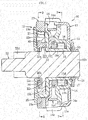
- FIG. 1 is a sectional view for illustrating an overall configuration of the clutch unit according to this embodiment.
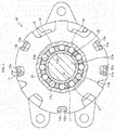
- FIG. 2 is a sectional view taken along the line P-P in FIG. 1 .
- FIG. 3 is a sectional view taken along the line Q-Q in FIG. 1 .
- a clutch unit 10 has a unit structure integrally comprising a lever-side clutch part 11 and a brake-side clutch part 12.
- the lever-side clutch part 11 is provided on an input side
- the brake-side clutch part 12 is provided on an output side.
- the lever-side clutch part 11 is configured to control transmission and interruption of a rotational torque to be input through a lever operation.
- the brake-side clutch part 12 has a reverse input interrupting function of transmitting the rotational torque from the lever-side clutch part 11 to the output side and interrupting the rotational torque to be reversely input from the output side.
- the lever-side clutch part 11 comprises a side plate 13, an outer ring 14, an inner ring 15, a plurality of cylindrical rollers 16, a cage 17, an inner centering spring 18, and an outer centering spring 19.
- the side plate 13 and the outer ring 14 are configured to receive the rotational torque to be input through the lever operation.
- the inner ring 15 is configured to transmit the rotational torque to be input from the outer ring 14 to the brake-side clutch part 12.
- the plurality of cylindrical rollers 16 are configured to control transmission and interruption of the rotational torque from the outer ring 14 through engagement and disengagement between the outer ring 14 and the inner ring 15.
- the cage 17 is configured to retain the cylindrical rollers 16 at equal intervals in a circumferential direction.
- the inner centering spring 18 is configured to return the cage 17 to a neutral state.
- the outer centering spring 19 is configured to return the outer ring 14 to a neutral state.
- the side plate 13 is fixed to the outer ring 14 by inserting claw parts 13a formed on an outer peripheral edge portion of the side plate 13 into cutout recessed parts 14a formed in an outer peripheral edge portion of the outer ring 14, and crimping the claw parts 13a, thereby forming an integrated input member of the lever-side clutch part 11.
- a plurality of cam surfaces 14b are formed at equal intervals in the circumferential direction on an inner periphery of the outer ring 14.
- the input of the rotational torque to the outer ring 14 is performed through an operation lever 43 (see FIG. 8 ), which is mounted to the side plate 13 by screwing or the like and is swingable in a vertical direction.
- the inner ring 15 comprises a tubular part 15a, a radially expanded part 15b, and a plurality of pillar parts 15c.
- the tubular part 15a is configured to receive an output shaft 22 inserted therethrough.
- the radially expanded part 15b is formed by extending an end portion of the tubular part 15a on a brake side radially outward.
- the plurality of pillar parts 15c are formed so as to protrude by bending an outer peripheral end portion of the radially expanded part 15b in an axial direction (see FIG. 3 ).
- a wedge gap 20 is formed between a cylindrical surface 15d formed on an outer periphery of the tubular part 15a of the inner ring 15 and each of the cam surfaces 14b formed on the inner periphery of the outer ring 14.
- the cylindrical rollers 16 are arranged in the wedge gaps 20 at the equal intervals in the circumferential direction by the cage 17.
- the inner centering spring 18 is a C-shaped elastic member having a circular cross section and is provided between the cage 17 and a cover 24, which is a stationary member of the brake-side clutch part 12. Both end portions of the inner centering spring 18 are locked to parts of the cage 17 and the cover 24.
- the inner centering spring 18 is spread outward as the cage 17 following the outer ring 14 rotates relative to the cover 24 in a stationary state, and an elastic force is thus accumulated.
- the inner centering spring 18 returns the cage 17 to the neutral state by the elastic force.
- the outer centering spring 19 positioned on a radially outer side with respect to the inner centering spring 18 is a C-shaped band-plate elastic member arranged between the outer ring 14 and the cover 24. Both end portions of the outer centering spring 19 are locked to parts of the outer ring 14 and the cover 24.
- the outer centering spring 19 is spread outward as the outer ring 14 rotates relative to the cover 24 in a stationary state, and an elastic force is thus accumulated.
- the outer centering spring 19 returns the outer ring 14 to the neutral state by the elastic force.
- the cage 17 is a cylindrical member made of resin in which a plurality of pockets 17a configured to receive the cylindrical rollers 16 are formed at the equal intervals in the circumferential direction. Both of the end portions of the inner centering spring 18 are locked to one end portion of the cage 17 in the axial direction, that is, an end portion of the brake-side clutch part 12 on the cover 24 side in the axial direction.
- the cage 17 is arranged between the outer ring 14 and the inner ring 15 in the radial direction, and is sandwiched between the outer ring 14 and the cover 24 of the brake-side clutch part 12 in the axial direction.
- the brake-side clutch part 12 which is of a type called "lock type" and has the reverse input interrupting function, mainly comprises the inner ring 15, the output shaft 22, an outer ring 23, the cover 24, a side plate 25, a plurality of pairs of cylindrical rollers 27, and plate springs 28.
- the inner ring 15 serves as an input member configured to receive the rotational torque to be input from the lever-side clutch part 11.
- the output shaft 22 serves as an output member configured to output the rotational torque from the lever-side clutch part 11.
- the outer ring 23, the cover 24, and the side plate 25 serve as a stationary member which is constrained in rotation.
- the plurality of pairs of cylindrical rollers 27 are configured to control interruption of the rotational torque to be reversely input from the output shaft 22 and transmission of the rotational torque to be input from the inner ring 15 through engagement and disengagement between the outer ring 23 and the output shaft 22.
- the plate springs 28 each have an N-shaped cross section, and are configured to apply a separating force in the circumferential direction to the pairs of cylindrical rollers 27.
- a large-diameter part 22b extending outward in the radial direction so as to have a larger diameter is formed integrally with a center portion of a shaft part 22a in the axial direction on which the tubular part 15a of the inner ring 15 is externally inserted.
- a pinion gear 22d configured to be coupled to a seat lifter part 41 (see FIG. 8 ) is coaxially formed at an end portion of the shaft part 22a on an output side.
- a washer 31 is press-fitted to an end portion of the shaft part 22a on an input side through intermediation of a wave washer 30, thereby preventing removal of the components of the lever-side clutch part 11.
- a plurality of flat cam surfaces 22e are formed at equal intervals in the circumferential direction on an outer periphery of the large-diameter part 22b of the output shaft 22.
- the two cylindrical rollers 27 and the one plate spring 28 interposed between the two cylindrical rollers 27 are arranged in each of wedge gaps 26 formed between each of the cam surfaces 22e of the large-diameter part 22b and a cylindrical inner peripheral surface 23a of the outer ring 23.
- the cylindrical rollers 27 and the plate springs 28 are arranged at the equal intervals in the circumferential direction by the pillar parts 15c of the inner ring 15.
- the inner ring 15 has a function as an input member of the brake-side clutch part 12 by transmitting the rotational torque to be input from the outer ring 14 of the lever-side clutch part 11 to the output shaft 22 through the radially expanded part 15b, and a function as a cage by receiving the cylindrical rollers 27 and the plate springs 28 in pockets 15h and retaining the cylindrical rollers 27 and the plate springs 28 at the equal intervals in the circumferential direction by the pillar parts 15c.
- the pillar parts 15c of the inner ring 15 are referred to as a cage 15c.
- the outer ring 23, the cover 24, and the side plate 25 are integrated as a stationary member of the brake-side clutch part 12 by inserting claw parts 25a formed on an outer peripheral edge portion of the side plate 25 into cutout recessed parts 23b formed in an outer peripheral edge portion of the outer ring 23 in a thick plate shape and cutout recessed parts 24a (see FIG. 4 ) formed in an outer peripheral edge portion of the cover 24, and crimping the claw parts 25a, thereby fixing the side plate 25 to the outer ring 23 and the cover 24 (see FIG. 3 ).
- the cage 17 and the outer ring 14 return to the respective neutral states by the elastic forces of both of the centering springs 18 and 19. Meanwhile, the inner ring 15 maintains a given rotational position.
- the inner ring 15 rotates in an inching manner by repetition of the rotation of the outer ring 14, that is, a pumping operation on the operation lever 43.
- the brake-side clutch part 12 in this embodiment has such a structure that the output shaft 22 comprises the slide gear 32 being a gear member mounted thereto, which meshes with the side plate 25 during interruption of the rotational torque and is released from the meshing state with the side plate 25 during transmission of the rotational torque.
- the slide gear 32 is arranged so as to be movable in the axial direction relative to the side plate 25 under a state in which the slide gear 32 is accommodated in an annular recessed part 22c formed in the large-diameter part 22b of the output shaft 22.
- the slide gear 32 is a ring-shaped member having, on an inner periphery thereof, a teeth part 32a (hereinafter referred to as internal teeth).
- a teeth part 25b (hereinafter referred to as external teeth) corresponding to the internal teeth 32a of the slide gear 32 is formed on an inner periphery of the side plate 25.
- the internal teeth 32a of the slide gear 32 and the external teeth 25b of the side plate 25 can mesh with each other.
- the cam mechanism 33 (see FIG. 1 ) configured to move the slide gear 32 in the axial direction, to thereby control the meshing of the slide gear 32 with the side plate 25 and the release of the meshing state is interposed between the slide gear 32 and the radially expanded part 15b of the inner ring 15 configured to function as an input member of the brake-side clutch part 12.
- the cammechanism 33 comprises the protrusions 32b formed on an end surface of the slide gear 32 so as to extend in the axial direction, and the cam grooves 15e formed in the circumferential direction in an end surface of the radially expanded part 15b of the inner ring 15 (see FIG. 4 ).
- the protrusions 32b are formed at a plurality of locations in the circumferential direction at equal intervals on the end surface of the slide gear 32.
- the cam grooves 15e are formed at a plurality of locations in the circumferential direction at equal intervals in the radially expanded part 15b of the inner ring 15 so as to correspond to the protrusions 32b of the slide gear 32.
- the four protrusions 32b and the four cam grooves 15e are exemplified in this embodiment, but the numbers are suitably set.
- Holes 22f through which the protrusions 32b of the slide gear 32 are to be inserted are formed through the large-diameter part 22b of the output shaft 22.
- the holes 22f are formed at a plurality of locations in the circumferential direction at equal intervals in the large-diameter part 22b of the output shaft 22 so as to correspond to the protrusions 32b of the slide gear 32.
- a distal-end curve forming part 32c of each of the protrusions 32b of the slide gear 32 is brought into abutment against a cam surface 15f of each of the cam grooves 15e of the inner ring 15 via each of the holes 22f of the large-diameter part 22b of the output shaft 22 in the cam mechanism 33.
- the cam surface 15f comprises a crest portion positioned at the center in the cam groove 15e, inclined portions extending from the crest portion toward both sides in the circumferential direction, and groove bottom portions extending from the inclined portions toward the both sides in the circumferential direction.
- stopper surfaces 15g are formed at both ends in a circumferential direction of the cam groove 15e so as to rise in the axial direction from the groove bottom portions of the cam surface 15f.
- the stopper surface 15g has a function of transmitting the rotational torque from the inner ring 15 of the lever-side clutch part 11 to the output shaft 22 through abutment against the protrusion 32b of the slide gear 32.
- the slide gear 32 is assembled to the output shaft 22 by accommodating the slide gear 32 in the annular recessed part 22c of the output shaft 22. On this occasion, as a result of the insertion of the protrusions 32b of the slide gear 32 through the holes 22f of the large-diameter part 22b of the output shaft 22, the movement of the slide gear 32 in the axial direction relative to the side plate 25 is permitted, and the movement (rotation) of the slide gear 32 in the circumferential direction relative to the output shaft 22 is prevented.
- an elastic member 34 configured to apply an elastic force toward a direction of releasing the meshing state between the slide gear 32 and the side plate 25 is interposed between the side plate 25 and the slide gear 32.
- the elastic member 34 for example, a wave spring having a ring shape as illustrated in FIG. 4 is preferred (see FIG. 4 ).
- the elastic member 34 is configured to apply its elastic force to the side plate 25 and the slide gear 32, to thereby press the slide gear 32 toward the output shaft 22 side with respect to the side plate 25 in the stationary state. As a result, the internal teeth 32a of the slide gear 32 are reliably disengaged from the external teeth 25b of the side plate 25 when the locked state of the output shaft 22 is released.
- the elastic member 34 has a function of applying the rotational resistance to the output shaft 22 via the slide gear 32 through friction forces generated respectively between the elastic member 34 and the side plate 25 and between the elastic member 34 and the slide gear 32. As a result, the state in which the cylindrical rollers 27 are locked to the outer ring 23 and the output shaft 22 can smoothly be released.
- the distal-end curve forming parts 32c of the protrusions 32b of the slide gear 32 are at neutral positions at which each of the distal-end curve forming parts 32c is brought into abutment against the crest portion of the cam surface 15f of each of the cam grooves 15e of the inner ring 15 in the cam mechanism 33 of the brake-side clutch part 12.
- Each of the protrusions 32b of the slide gear 32 moves from the crest portion of each of the cam surfaces 15f to the groove bottom portion via the inclined portion as a result of the movement of the cam grooves 15e of the inner ring 15 in the circumferential direction and the movement of the protrusions 32b of the slide gear 32 in the axial direction. In this way, each of the protrusions 32b of the slide gear 32 is brought into abutment against the groove bottom portion of the cam surface 15f of each of the cam grooves 15e.
- the slide gear 32 moves in the axial direction (see the outlined arrow of FIG. 7 ) so as to be separated from the side plate 25 by the elastic force of the elastic member 34 as a result of the phase shift between each of the protrusions 32b of the slide gear 32 and each of the cam grooves 15e of the inner ring 15.
- the rotational resistance can be applied to the output shaft 22 via the slide gear 32 through the friction forces generated respectively between the elastic member 34 and the side plate 25 and between the elastic member 34 and the slide gear 32.
- the locked state of the output shaft 22 can smoothly be released through the lever operation.
- the cam mechanism 33 (the protrusions 32b of the slide gear 32 and the cam grooves 15e of the inner ring 15) configured to move the slide gear 32 in the axial direction to control the meshing between the slide gear 32 and the side plater 25 and the release of the meshing state is interposed between the slide gear 32 and the inner ring 15.
- the structure in which the cylindrical rollers 27 are engaged with the wedge gaps 26 between the outer ring 23 and the output shaft 22 is required in addition to the structure in which the internal teeth 32a of the slide gear 32 and the external teeth 25b of the side plate 25 mesh with each other.
- FIG. 8 is a view for illustrating the seat 40 installed in a cabin of an automobile.
- the seat 40 comprises a seating seat 48 and a backrest seat 42, and a height of a seat surface of the seating seat 48 is adjusted by the seat lifter part 41.
- the height adjustment of the seating seat 48 is performed through the operation lever 43 mounted to the side plate 13 of the lever-side clutch part 11 (see FIG. 1 ) in the clutch unit 10.
- the seat lifter part 41 has the following structure. One ends of link members 45 and 46 are pivotably mounted to a slidable member 44. Another ends of the link members 45 and 46 are pivotably mounted to the seating seat 48. A sector gear 47 is provided integrally with another end of the link member 45. The sector gear 47 meshes with the pinion gear 22d of the output shaft 22 of the clutch unit 10.
- the locked state of the brake-side clutch part 12 (see FIG. 1 ) is released by a lever operation in the lever-side clutch part 11, in other words, by swinging the operation lever 43 downward.
- the seating surface of the seating seat 48 can smoothly be lowered by applying the appropriate rotational resistance to the output shaft 22 through the elastic member 34 upon the unlocking of the brake-side clutch part 12.
Landscapes
- Engineering & Computer Science (AREA)
- General Engineering & Computer Science (AREA)
- Mechanical Engineering (AREA)
- Aviation & Aerospace Engineering (AREA)
- Transportation (AREA)
- Braking Arrangements (AREA)
- Seats For Vehicles (AREA)
Abstract
Description
- The present invention relates to a clutch unit comprising a lever-side clutch part, which is configured to receive a rotational torque to be input through a lever operation, and a brake-side clutch part, which is configured to transmit the rotational torque from the lever-s ide clutch part to an output side and interrupt a rotational torque from the output side.
- In general, in a clutch unit using engagement elements such as cylindrical rollers or balls, a clutch part is arranged between an input member and an output member. The clutch part is configured to engage and disengage the engagement elements, such as cylindrical rollers or balls, between the input member and the output member, to thereby control transmission and interruption of a rotational torque.
- The present applicant has previously proposed a clutch unit assembled to a seat lifter part for an automobile, which is configured to vertically adjust a seat through a lever operation (for example, see Patent Literature 1). The clutch unit disclosed in Patent Literature 1 includes a lever-side clutch part, which is configured to receive a rotational torque to be input through a lever operation, and a brake-side clutch part, which is configured to transmit the rotational torque from the lever-side clutch part to an output side and interrupt a rotational torque from the output side.
- The lever-side clutch part mainly includes an outer ring, an inner ring, a plurality of cylindrical rollers, a cage, and two centering springs. The outer ring is configured to receive the rotational torque to be input through the lever operation. The inner ring is configured to transmit the rotational torque to be input from the outer ring to the brake-side clutch part. The plurality of cylindrical rollers are configured to control the transmission and interruption of the rotational torque from the outer ring through engagement and disengagement in wedge gaps between the outer ring and the inner ring. The cage is configured to retain the cylindrical rollers at equal intervals in a circumferential direction. The two centering springs are configured to accumulate elastic forces with the rotational torque from the outer ring, and return the cage and the outer ring to respective neutral states by the accumulated elastic forces when the input of the rotational torque is lost.
- The brake-side clutch part mainly includes an outer ring, a side plate, an output shaft, a plurality of pairs of cylindrical rollers, plate springs, a cage, and a friction ring. The outer ring and the side plate are constrained in rotation. The output shaft is configured to output the rotational torque. The plurality of pairs of cylindrical rollers are configured to control interruption of the rotational torque from the output shaft and transmission of the rotational torque from the lever-side clutch part through engagement and disengagement in wedge gaps between the outer ring and the output shaft. The plate springs are configured to apply a separating force to the pairs of cylindrical rollers. The cage is configured to retain the pairs of the cylindrical rollers and the plate springs at equal intervals in the circumferential direction. The friction ring is configured to apply a rotational resistance to the output shaft.
- The cage of the brake-side clutch part is formed integrally with the inner ring of the lever-side clutch part. With this, in the brake-side clutch part, the cage has a function of serving as an input member configured to receive the rotational torque to be input from the lever-side clutch part in addition to a function of retaining the pairs of cylindrical rollers and the plate springs at the equal intervals in the circumferential direction.
- The friction ring is mounted and fixed to the side plate, and is configured to apply the rotational resistance to the output shaft during a lever operation by a friction force generated in a portion in contact with the output shaft. Moreover, protrusions configured to transmit the rotational torque from the inner ring of the lever-side clutch part to the output shaft are formed on the output shaft. The protrusions are respectively inserted into and arranged with a circumferential clearance in holes formed in the cage integrated with the inner ring of the lever-side clutch part.
- In the lever-side clutchpart, when the rotational torque is input to the outer ring through the lever operation, the cylindrical rollers are engaged with the wedge gaps between the outer ring and the inner ring. The rotational torque is transmitted to the inner ring thorough the engagement of the cylindrical rollers in the wedge gaps, thereby rotating the inner ring. On this occasion, as the outer ring and the cage rotate, the elastic forces are accumulated in both of the centering springs.
- When the input of the rotational torque is lost, the cage and the outer ring return to the respective neutral states by the elastic forces of both of the centering springs while the inner ring maintains a given rotational position. Thus, the inner ring rotates in an inching manner by repetition of the rotation of the outer ring, that is, a pumping operation on an operation lever.
- In the brake-side clutch part, when a rotational torque is reversely input to the output shaft by seating on the seat, the cylindrical rollers are engaged with the wedge gaps between the output shaft and the outer ring, and the output shaft is thus locked to the outer ring. In such a manner, the rotational torque reversely input from the output shaft is locked in the brake-side clutch part, and the reverse transmission to the lever-side clutch part is interrupted. As a result, the seat cannot be vertically adjusted.
- Meanwhile, when the rotational torque is input from the inner ring of the lever-side clutch part to the cage of the brake-side clutch part, the cage rotates to be brought into abutment against the cylindrical rollers, and presses the cylindrical rollers against the elastic forces of the plate springs, thereby disengaging the cylindrical rollers from the wedge gaps between the outer ring and the output shaft. As a result of the disengagement of the cylindrical rollers from the wedge gaps, the locked state of the output shaft is released, and the output shaft thus becomes rotatable. When the locked state of the output shaft is released, the rotational resistance is applied to the output shaft by the friction ring.
- When the cage of the brake-side clutch part further rotates, the clearance between each of the holes of the cage and each of the protrusions of the output shaft decreases, and the cage is brought into abutment against the output shaft in a rotation direction. As a result, the rotational torque from the cage is transmitted to the output shaft, and the output shaft thus rotates. In other words, when the cage rotates in the inching manner, the output shaft also rotates in the inching manner. The inching rotation of the output shaft enables the vertical adjustment of the seat.
- Patent Literature 1:
JP 5207779 B2 - Incidentally, in the related-art clutch unit disclosed in Patent Literature 1, when the rotational torque is reversely input to the output shaft by the seating on the seat, the cylindrical rollers are engaged with the wedge gaps between the output shaft and the outer ring, and the output shaft is thus locked to the outer ring.
- In such a manner, the rotational torque reversely input from the output shaft is locked in the brake-side clutch part, and the reverse transmission to the lever-side clutch part is interrupted. As a result, the seat is fixed, and cannot thus be vertically adjusted.
- In the clutch unit assembled to the seat lifter part for an automobile, when a vertical vibration is generated during travelling of a vehicle on a rough road or the like in a seating state on the seat, a rotational torque in a forward direction and a rotational torque in a backward direction are reversely input in an alternate and continuous manner to the output shaft.
- On this occasion, in the brake-side clutch part, contact positions of the cylindrical rollers in the wedge gaps between the outer ring and the output shaft are slightly displaced, or hysteresis of an elastic deformation is present in the output shaft, the outer ring, the cylindrical rollers, and the plate springs which bear the rotational torque. Thus, the output shaft gradually rotates. As a result, there occurs such a phenomenon in which the seat is slightly lowered.
- The present invention has been made in view of the above-mentioned problem, and has an object to provide a clutch unit having a structure capable of reliably locking an output shaft even when rotational torques in forward and backward directions are reversely input in a continuous manner to the output shaft.
- According to one embodiment of the present invention, there is provided a clutch unit, comprising: a lever-side clutch part, which is provided on an input side, and is configured to control transmission and interruption of a rotational torque to be input through a lever operation; and a brake-side clutch part, which is provided on an output side, and is configured to transmit the rotational torque from the lever-side clutch part to the output side, and interrupt a rotational torque to be reversely input from the output side.
- It is assumed that the brake-side clutch part in one embodiment of the present invention comprises : a stationary member, which is constrained in rotation; an output member configured to output the rotation; and an engaging element configured to control the interruption of the rotational torque to be reversely input from the output member and the transmission of the rotational torque to be input from the lever-side clutch part through engagement and disengagement between the stationary member and the output member.
- As a technical measure for achieving the above-mentioned object, in the brake-side clutch part, the output member comprises a gear member mounted thereto, which meshes with the stationary member during interruption of the rotational torque and is released from the meshing state with the stationary member during transmission of the rotational torque.
- With the present invention, the output member comprises the gear member mounted thereto, and even when a rotational torque in a forward direction and a rotational torque in a backward direction are reversely input in an alternate and continuous manner to the output member while the output member is locked, the gear member mounted to the output member meshes with the stationary member, thereby being capable of reliably locking the output member.
- In the brake-side clutch part, even when contact positions of the engaging elements are slightly displaced between the stationary member and the output member, or hysteresis of elastic deformation is present in the output member, the stationary member, and the engaging elements which bear the rotational torque, the gradual rotation of the output member can be prevented through the meshing between the stationary member and the gear member mounted to the output member.
- According to one or more embodiments of the present invention, the gear member is arranged so as to be movable in an axial direction relative to the stationary member, and a cam mechanism configured to move the gear member in the axial direction to control meshing with the stationary member and release of the meshing state is interposed between the gear member and an input member configured to receive the rotational torque to be input from the lever-side clutch part.
- When such a structure is employed, the gear member can be moved in the axial direction by the cam mechanism. Thus, the meshing between the gear member and the stationary member and the release of the meshing state can easily be performed through the movement of the gear member in the axial direction.
- According to one or more embodiments of the present invention, an elastic member configured to apply an elastic force toward a direction of releasing the meshing state between the gear member and the stationary member is interposed between the stationary member and the gear member.
- When such a structure is employed, the elastic force of the elastic member can be applied to the stationary member and the gear member. Thus, the meshing state between the gear member and the stationary member can reliably be released when the locked state of the output member is released. Moreover, on this occasion, the rotational resistance can be applied to the output member by a friction force between the elastic member and the stationary member and a friction force between the elastic member and the gear member. Thus, the locked state of the output member can smoothly be released.
- In the clutch unit according to one embodiment of the present invention, the lever-side clutch part and the brake-side clutch part are assembled to a seat lifter part for an automobile. With such a structure, the clutch unit is suitable for use in an automobile.
- According to the present invention, the output member comprises the gear member mounted thereto. Thus, even when the rotational torque in the forward direction and the rotational torque in the backward direction are reversely input in an alternate and continuous manner to the output member while the output member is locked, the gear member mounted to the output member meshes with the stationary member, thereby being capable of reliably locking the output member.
- In the brake-side clutch part, even when contact positions of the engaging elements are slightly displaced between the stationary member and the output member, or hysteresis of elastic deformation is present in the output member, the stationary member, and the engaging elements which bear the rotational torque, the gradual rotation of the output member can be prevented through the meshing between the stationary member and the gear member mounted to the output member.
- As a result, in a case in which the brake-side clutch part is assembled to the seat lifter part for an automobile, even when a vertical vibration is generated during travelling of a vehicle on a rough road or the like in a seating state on the seat, occurrence of the phenomenon in which the seat is slightly lowered can be prevented.
-
-
FIG. 1 is a sectional view for illustrating an overall configuration of a clutch unit according to an embodiment of the present invention.FIG. 2 is a sectional view taken along the line P-P inFIG. 1 . -
FIG. 3 is a sectional view taken along the line Q-Q inFIG. 1 . -
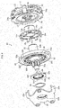
FIG. 4 is an assembly exploded perspective view for illustrating the clutch unit ofFIG. 1 . -
FIG. 5 is a partial enlarged sectional view for illustrating a cam mechanism in a neutral state in the clutch unit ofFIG. 1 . -
FIG. 6 is a partial enlarged sectional view for illustrating the cam mechanism in an operation state in the clutch unit ofFIG. 1 . -
FIG. 7 is a sectional view for illustrating an operation state of the clutch unit ofFIG. 1 . -
FIG. 8 is a configuration view for illustrating a seat for an automobile and a seat lifter part. - Detailed description is now given of a clutch unit according to an embodiment of the present invention with reference to the drawings.
FIG. 1 is a sectional view for illustrating an overall configuration of the clutch unit according to this embodiment.FIG. 2 is a sectional view taken along the line P-P inFIG. 1 .FIG. 3 is a sectional view taken along the line Q-Q inFIG. 1 . Before description of a characteristic configuration of this embodiment, description is now given of the overall configuration of the clutch unit. - As illustrated in
FIG. 1 , aclutch unit 10 according to this embodiment has a unit structure integrally comprising a lever-sideclutch part 11 and a brake-sideclutch part 12. The lever-sideclutch part 11 is provided on an input side, and the brake-sideclutch part 12 is provided on an output side. The lever-sideclutch part 11 is configured to control transmission and interruption of a rotational torque to be input through a lever operation. The brake-sideclutch part 12 has a reverse input interrupting function of transmitting the rotational torque from the lever-sideclutch part 11 to the output side and interrupting the rotational torque to be reversely input from the output side. - As illustrated in
FIG. 1 andFIG. 2 , the lever-sideclutch part 11 comprises aside plate 13, anouter ring 14, aninner ring 15, a plurality ofcylindrical rollers 16, acage 17, an inner centeringspring 18, and an outer centeringspring 19. Theside plate 13 and theouter ring 14 are configured to receive the rotational torque to be input through the lever operation. Theinner ring 15 is configured to transmit the rotational torque to be input from theouter ring 14 to the brake-sideclutch part 12. The plurality ofcylindrical rollers 16 are configured to control transmission and interruption of the rotational torque from theouter ring 14 through engagement and disengagement between theouter ring 14 and theinner ring 15. Thecage 17 is configured to retain thecylindrical rollers 16 at equal intervals in a circumferential direction. The inner centeringspring 18 is configured to return thecage 17 to a neutral state. The outer centeringspring 19 is configured to return theouter ring 14 to a neutral state. - In the lever-side
clutch part 11, theside plate 13 is fixed to theouter ring 14 by insertingclaw parts 13a formed on an outer peripheral edge portion of theside plate 13 into cutout recessedparts 14a formed in an outer peripheral edge portion of theouter ring 14, and crimping theclaw parts 13a, thereby forming an integrated input member of the lever-sideclutch part 11. A plurality of cam surfaces 14b are formed at equal intervals in the circumferential direction on an inner periphery of theouter ring 14. The input of the rotational torque to theouter ring 14 is performed through an operation lever 43 (seeFIG. 8 ), which is mounted to theside plate 13 by screwing or the like and is swingable in a vertical direction. - The
inner ring 15 comprises atubular part 15a, a radially expandedpart 15b, and a plurality ofpillar parts 15c. Thetubular part 15a is configured to receive anoutput shaft 22 inserted therethrough. The radially expandedpart 15b is formed by extending an end portion of thetubular part 15a on a brake side radially outward. The plurality ofpillar parts 15c are formed so as to protrude by bending an outer peripheral end portion of the radially expandedpart 15b in an axial direction (seeFIG. 3 ). Awedge gap 20 is formed between acylindrical surface 15d formed on an outer periphery of thetubular part 15a of theinner ring 15 and each of the cam surfaces 14b formed on the inner periphery of theouter ring 14. Thecylindrical rollers 16 are arranged in thewedge gaps 20 at the equal intervals in the circumferential direction by thecage 17. - The inner centering
spring 18 is a C-shaped elastic member having a circular cross section and is provided between thecage 17 and acover 24, which is a stationary member of the brake-sideclutch part 12. Both end portions of the inner centeringspring 18 are locked to parts of thecage 17 and thecover 24. When the rotational torque to be input from theouter ring 14 through the lever operation is applied, the inner centeringspring 18 is spread outward as thecage 17 following theouter ring 14 rotates relative to thecover 24 in a stationary state, and an elastic force is thus accumulated. When the rotational torque to be input from theouter ring 14 is released, the inner centeringspring 18 returns thecage 17 to the neutral state by the elastic force. - The outer centering
spring 19 positioned on a radially outer side with respect to the inner centeringspring 18 is a C-shaped band-plate elastic member arranged between theouter ring 14 and thecover 24. Both end portions of the outer centeringspring 19 are locked to parts of theouter ring 14 and thecover 24. When the rotational torque to be input from theouter ring 14 through the lever operation is applied, the outer centeringspring 19 is spread outward as theouter ring 14 rotates relative to thecover 24 in a stationary state, and an elastic force is thus accumulated. When the rotational torque to be input from theouter ring 14 is released, the outer centeringspring 19 returns theouter ring 14 to the neutral state by the elastic force. - The
cage 17 is a cylindrical member made of resin in which a plurality ofpockets 17a configured to receive thecylindrical rollers 16 are formed at the equal intervals in the circumferential direction. Both of the end portions of the inner centeringspring 18 are locked to one end portion of thecage 17 in the axial direction, that is, an end portion of the brake-sideclutch part 12 on thecover 24 side in the axial direction. Thecage 17 is arranged between theouter ring 14 and theinner ring 15 in the radial direction, and is sandwiched between theouter ring 14 and thecover 24 of the brake-sideclutch part 12 in the axial direction. - As illustrated in FIG. land
FIG. 3 , the brake-sideclutch part 12, which is of a type called "lock type" and has the reverse input interrupting function, mainly comprises theinner ring 15, theoutput shaft 22, anouter ring 23, thecover 24, aside plate 25, a plurality of pairs ofcylindrical rollers 27, and plate springs 28. Theinner ring 15 serves as an input member configured to receive the rotational torque to be input from the lever-sideclutch part 11. Theoutput shaft 22 serves as an output member configured to output the rotational torque from the lever-sideclutch part 11. Theouter ring 23, thecover 24, and theside plate 25 serve as a stationary member which is constrained in rotation. The plurality of pairs ofcylindrical rollers 27 are configured to control interruption of the rotational torque to be reversely input from theoutput shaft 22 and transmission of the rotational torque to be input from theinner ring 15 through engagement and disengagement between theouter ring 23 and theoutput shaft 22. The plate springs 28 each have an N-shaped cross section, and are configured to apply a separating force in the circumferential direction to the pairs ofcylindrical rollers 27. - In the
output shaft 22, a large-diameter part 22b extending outward in the radial direction so as to have a larger diameter is formed integrally with a center portion of ashaft part 22a in the axial direction on which thetubular part 15a of theinner ring 15 is externally inserted. Apinion gear 22d configured to be coupled to a seat lifter part 41 (seeFIG. 8 ) is coaxially formed at an end portion of theshaft part 22a on an output side. Moreover, awasher 31 is press-fitted to an end portion of theshaft part 22a on an input side through intermediation of awave washer 30, thereby preventing removal of the components of the lever-sideclutch part 11. - A plurality of
flat cam surfaces 22e are formed at equal intervals in the circumferential direction on an outer periphery of the large-diameter part 22b of theoutput shaft 22. The twocylindrical rollers 27 and the oneplate spring 28 interposed between the twocylindrical rollers 27 are arranged in each ofwedge gaps 26 formed between each of the cam surfaces 22e of the large-diameter part 22b and a cylindrical innerperipheral surface 23a of theouter ring 23. Thecylindrical rollers 27 and the plate springs 28 are arranged at the equal intervals in the circumferential direction by thepillar parts 15c of theinner ring 15. - In this case, the
inner ring 15 has a function as an input member of the brake-sideclutch part 12 by transmitting the rotational torque to be input from theouter ring 14 of the lever-sideclutch part 11 to theoutput shaft 22 through the radially expandedpart 15b, and a function as a cage by receiving thecylindrical rollers 27 and the plate springs 28 inpockets 15h and retaining thecylindrical rollers 27 and the plate springs 28 at the equal intervals in the circumferential direction by thepillar parts 15c. Hereinafter, thepillar parts 15c of theinner ring 15 are referred to as acage 15c. - The
outer ring 23, thecover 24, and theside plate 25 are integrated as a stationary member of the brake-sideclutch part 12 by insertingclaw parts 25a formed on an outer peripheral edge portion of theside plate 25 into cutout recessedparts 23b formed in an outer peripheral edge portion of theouter ring 23 in a thick plate shape and cutout recessedparts 24a (seeFIG. 4 ) formed in an outer peripheral edge portion of thecover 24, and crimping theclaw parts 25a, thereby fixing theside plate 25 to theouter ring 23 and the cover 24 (seeFIG. 3 ). - Description is now given of an operation example of the lever-side
clutch part 11 and the brake-sideclutch part 12 having the configuration described above. - In the lever-side
clutch part 11, when the rotational torque is input to theouter ring 14 through the lever operation, thecylindrical rollers 16 are engaged with thewedge gaps 20 between theouter ring 14 and theinner ring 15. The rotational torque is transmitted to theinner ring 15 thorough the engagement of thecylindrical rollers 16 in thewedge gaps 20, thereby rotating theinner ring 15. On this occasion, as theouter ring 14 and thecage 17 rotate, the elastic forces are accumulated in both of the centeringsprings - When the input of the rotational torque is lost, the
cage 17 and theouter ring 14 return to the respective neutral states by the elastic forces of both of the centeringsprings inner ring 15 maintains a given rotational position. Thus, theinner ring 15 rotates in an inching manner by repetition of the rotation of theouter ring 14, that is, a pumping operation on theoperation lever 43. - In the brake-side
clutch part 12, even when a rotational torque is reversely input to theoutput shaft 22 by seating on aseat 40, thecylindrical rollers 27 are engaged with thewedge gaps 26 between theoutput shaft 22 and theouter ring 23, and theoutput shaft 22 is thus locked to theouter ring 23. In such a manner, the rotational torque to be reversely input from theoutput shaft 22 is locked by the brake-sideclutch part 12, and reverse transmission to the lever-sideclutch part 11 is interrupted. As a result, theseat 40 is fixed, and cannot thus be vertically adjusted. - Meanwhile, when the rotational torque is input from the
inner ring 15 of the lever-sideclutch part 11 to thecage 15c through the lever operation, thecage 15c rotates to be brought into abutment against thecylindrical rollers 27, and presses thecylindrical rollers 27 against the elastic forces of the plate springs 28. With this, thecylindrical rollers 27 are disengaged from thewedge gaps 26. As a result of the disengagement of thecylindrical rollers 27 from thewedge gaps 26, the locked state of theoutput shaft 22 is released, and theoutput shaft 22 thus becomes rotatable. - When the
cage 15c further rotates, the rotational torque from the lever-sideclutch part 11 is transmitted to theoutput shaft 22 through abutment ofstopper surfaces 15g ofcam grooves 15e in acam mechanism 33 described later againstprotrusions 32b of a slide gear 32 (seeFIG. 6 ), thereby rotating theoutput shaft 22. In other words, when thecage 15c rotates in the inching manner, theoutput shaft 22 also rotates in the inching manner. As a result, theseat 40 can be vertically adjusted. - The overall configuration of the
clutch unit 10 according to this embodiment is as described above. Detailed description is now given of the characteristic configuration of theclutch unit 10. - While the
output shaft 22 is locked in the brake-sideclutch part 12, when a vertical vibration is generated during travelling of a vehicle on a rough road or the like in a seating state on the seat 40 (seeFIG. 8 ), a rotational torque in a forward direction and a rotational torque in a backward direction are reversely input in an alternate and continuous manner to theoutput shaft 22. In order to reliably lock theoutput shaft 22 even when the rotational torques in the forward and backward directions are reversely input in a continuous manner to theoutput shaft 22, the following structure is provided. - As illustrated in
FIG. 1 ,FIG. 3 , andFIG. 4 , the brake-sideclutch part 12 in this embodiment has such a structure that theoutput shaft 22 comprises theslide gear 32 being a gear member mounted thereto, which meshes with theside plate 25 during interruption of the rotational torque and is released from the meshing state with theside plate 25 during transmission of the rotational torque. Theslide gear 32 is arranged so as to be movable in the axial direction relative to theside plate 25 under a state in which theslide gear 32 is accommodated in an annular recessedpart 22c formed in the large-diameter part 22b of theoutput shaft 22. - The
slide gear 32 is a ring-shaped member having, on an inner periphery thereof, ateeth part 32a (hereinafter referred to as internal teeth). In correspondence to this configuration, ateeth part 25b (hereinafter referred to as external teeth) corresponding to theinternal teeth 32a of theslide gear 32 is formed on an inner periphery of theside plate 25. Theinternal teeth 32a of theslide gear 32 and theexternal teeth 25b of theside plate 25 can mesh with each other. - Meanwhile, the cam mechanism 33 (see
FIG. 1 ) configured to move theslide gear 32 in the axial direction, to thereby control the meshing of theslide gear 32 with theside plate 25 and the release of the meshing state is interposed between theslide gear 32 and the radially expandedpart 15b of theinner ring 15 configured to function as an input member of the brake-sideclutch part 12. - The
cammechanism 33 comprises theprotrusions 32b formed on an end surface of theslide gear 32 so as to extend in the axial direction, and thecam grooves 15e formed in the circumferential direction in an end surface of the radially expandedpart 15b of the inner ring 15 (seeFIG. 4 ). - The
protrusions 32b are formed at a plurality of locations in the circumferential direction at equal intervals on the end surface of theslide gear 32. Moreover, thecam grooves 15e are formed at a plurality of locations in the circumferential direction at equal intervals in the radially expandedpart 15b of theinner ring 15 so as to correspond to theprotrusions 32b of theslide gear 32. The fourprotrusions 32b and the fourcam grooves 15e are exemplified in this embodiment, but the numbers are suitably set. -
Holes 22f through which theprotrusions 32b of theslide gear 32 are to be inserted are formed through the large-diameter part 22b of theoutput shaft 22. Theholes 22f are formed at a plurality of locations in the circumferential direction at equal intervals in the large-diameter part 22b of theoutput shaft 22 so as to correspond to theprotrusions 32b of theslide gear 32. - As illustrated in
FIG. 5 and FIG. 6 , a distal-endcurve forming part 32c of each of theprotrusions 32b of theslide gear 32 is brought into abutment against acam surface 15f of each of thecam grooves 15e of theinner ring 15 via each of theholes 22f of the large-diameter part 22b of theoutput shaft 22 in thecam mechanism 33. Thecam surface 15f comprises a crest portion positioned at the center in thecam groove 15e, inclined portions extending from the crest portion toward both sides in the circumferential direction, and groove bottom portions extending from the inclined portions toward the both sides in the circumferential direction. - Moreover,
stopper surfaces 15g are formed at both ends in a circumferential direction of thecam groove 15e so as to rise in the axial direction from the groove bottom portions of thecam surface 15f. Thestopper surface 15g has a function of transmitting the rotational torque from theinner ring 15 of the lever-sideclutch part 11 to theoutput shaft 22 through abutment against theprotrusion 32b of theslide gear 32. - In other words, when the
inner ring 15 is rotated by the rotational torque from the lever-sideclutch part 11, in a rotation direction, thestopper surface 15g of each of thecam grooves 15e of theinner ring 15 is brought into abutment against each of theprotrusions 32b of theslide gear 32 protruding from each of theholes 22f of the large-diameter part 22b of theoutput shaft 22 in thecam mechanism 33. The rotational torque of theinner ring 15 is transmitted to theoutput shaft 22 through abutment between the stopper surfaces 15g of thecam grooves 15e and theprotrusions 32b of theslide gear 32, and theoutput shaft 22 thus rotates. - The
slide gear 32 is assembled to theoutput shaft 22 by accommodating theslide gear 32 in the annular recessedpart 22c of theoutput shaft 22. On this occasion, as a result of the insertion of theprotrusions 32b of theslide gear 32 through theholes 22f of the large-diameter part 22b of theoutput shaft 22, the movement of theslide gear 32 in the axial direction relative to theside plate 25 is permitted, and the movement (rotation) of theslide gear 32 in the circumferential direction relative to theoutput shaft 22 is prevented. - Moreover, as illustrated in
FIG. 1 andFIG. 4 , anelastic member 34 configured to apply an elastic force toward a direction of releasing the meshing state between theslide gear 32 and theside plate 25 is interposed between theside plate 25 and theslide gear 32. As theelastic member 34, for example, a wave spring having a ring shape as illustrated inFIG. 4 is preferred (seeFIG. 4 ). - The
elastic member 34 is configured to apply its elastic force to theside plate 25 and theslide gear 32, to thereby press theslide gear 32 toward theoutput shaft 22 side with respect to theside plate 25 in the stationary state. As a result, theinternal teeth 32a of theslide gear 32 are reliably disengaged from theexternal teeth 25b of theside plate 25 when the locked state of theoutput shaft 22 is released. - Moreover, the
elastic member 34 has a function of applying the rotational resistance to theoutput shaft 22 via theslide gear 32 through friction forces generated respectively between theelastic member 34 and theside plate 25 and between theelastic member 34 and theslide gear 32. As a result, the state in which thecylindrical rollers 27 are locked to theouter ring 23 and theoutput shaft 22 can smoothly be released. - As illustrated in
FIG. 5 , in theclutch unit 10 according to this embodiment, under a state in which the rotational torque is not input from theouter ring 14 of the lever-sideclutch part 11, the distal-endcurve forming parts 32c of theprotrusions 32b of theslide gear 32 are at neutral positions at which each of the distal-endcurve forming parts 32c is brought into abutment against the crest portion of thecam surface 15f of each of thecam grooves 15e of theinner ring 15 in thecam mechanism 33 of the brake-sideclutch part 12. - Under the state in which the
protrusions 32b of theslide gear 32 are at the neutral positions of thecam grooves 15e, theslide gear 32 is pressed toward theside plate 25 side in the axial direction against the elastic force of theelastic member 34, and theinternal teeth 32a of theslide gear 32 and theexternal teeth 25b of theside plate 25 mesh with each other (seeFIG. 1 ). As a result, theoutput shaft 22 is brought into the locked state. - In this locked state of the
output shaft 22, even when the vertical vibration is generated during travelling of a vehicle on a rough road or the like in the seating state on the seat 40 (seeFIG. 8 ), and a rotational torque in the forward direction and a rotational torque in the backward direction are reversely input in an alternate and continuous manner to theoutput shaft 22 as a result of the vertical vibration, theinternal teeth 32a of theslide gear 32 mesh with theexternal teeth 25b of theside plate 25, and theoutput shaft 22 can thus reliably be locked. - In the brake-side
clutch part 12, even when contact positions of thecylindrical rollers 27 are slightly displaced between theouter ring 23 and theoutput shaft 22, or hysteresis of an elastic deformation is present in theoutput shaft 22, theouter ring 23, and thecylindrical rollers 27 which bear the rotational torque, a gradual rotation of theoutput shaft 22 can be prevented through the meshing between theinternal teeth 32a of theslide gear 32 and theexternal teeth 25b of theside plate 25. - As a result, occurrence of a phenomenon in which the
seat 40 is slightly lowered can be prevented. Moreover, the meshing between theinternal teeth 32a of theslide gear 32 and theexternal teeth 25b of theside plate 25 enables bearing of a high torque on the brake-sideclutch part 12. - Meanwhile, when the rotational torque is input from the
outer ring 14 of the lever-sideclutch part 11, a phase shift occurs between theprotrusions 32b of theslide gear 32 and thecam grooves 15e of theinner ring 15 in thecam mechanism 33 of the brake-sideclutch part 12. - In other words, when, as indicated by the solid arrow of
FIG. 6 , thecam surface 15f of each of thecam grooves 15e of theinner ring 15 moves in the circumferential direction relative to the distal-endcurve forming part 32c of each of theprotrusions 32b of theslide gear 32 as a result of the rotation of theinner ring 15, as indicated by the broken arrow ofFIG. 6 , each of theprotrusions 32b of theslide gear 32 moves axially toward a direction of protruding from each of theholes 22f of theoutput shaft 22 by the elastic force of theelastic member 34. - Each of the
protrusions 32b of theslide gear 32 moves from the crest portion of each of the cam surfaces 15f to the groove bottom portion via the inclined portion as a result of the movement of thecam grooves 15e of theinner ring 15 in the circumferential direction and the movement of theprotrusions 32b of theslide gear 32 in the axial direction. In this way, each of theprotrusions 32b of theslide gear 32 is brought into abutment against the groove bottom portion of thecam surface 15f of each of thecam grooves 15e. - As described above, as illustrated in
FIG. 7 , theslide gear 32 moves in the axial direction (see the outlined arrow ofFIG. 7 ) so as to be separated from theside plate 25 by the elastic force of theelastic member 34 as a result of the phase shift between each of theprotrusions 32b of theslide gear 32 and each of thecam grooves 15e of theinner ring 15. - As a result of this movement of the
slide gear 32 in the axial direction, theinternal teeth 32a of theslide gear 32 are disengaged from theexternal teeth 25b of theside plate 25, and the meshing state between theinternal teeth 32a of theslide gear 32 and theexternal teeth 25b of theside plate 25 is thus released. As a result, the locked state of theoutput shaft 22 is released, and theoutput shaft 22 is brought into a rotatable state relative to theouter ring 23. - In this embodiment, there is employed a structure in which the
elastic member 34 configured to apply the elastic force toward the direction of releasing the meshing state between theslide gear 32 and theside plate 25 is interposed between theside plate 25 and theslide gear 32 of the brake-sideclutch part 12. With this configuration, theinternal teeth 32a of theslide gear 32 can reliably be disengaged from theexternal teeth 25b of theside plate 25 by the elastic force of theelastic member 34 when the locked state of theoutput shaft 22 is released. - Moreover, when the locked state of the
output shaft 22 is released, the rotational resistance can be applied to theoutput shaft 22 via theslide gear 32 through the friction forces generated respectively between theelastic member 34 and theside plate 25 and between theelastic member 34 and theslide gear 32. As a result, the locked state of theoutput shaft 22 can smoothly be released through the lever operation. - Then, when the
inner ring 15 further rotates, thestopper surface 15g of each of thecam grooves 15e of theinner ring 15 is brought into abutment against each of theprotrusions 32b of theslide gear 32 in the rotation direction. When each of the stopper surfaces 15g presses each of theprotrusions 32b in the rotation direction as a result of the abutment between the stopper surfaces 15g and theprotrusions 32b, the rotational torque to be input from theinner ring 15 is transmitted to theoutput shaft 22 via theprotrusions 32b of theslide gear 32, thereby rotating theoutput shaft 22. - In this embodiment, there is employed a structure in which the cam mechanism 33 (the
protrusions 32b of theslide gear 32 and thecam grooves 15e of the inner ring 15) configured to move theslide gear 32 in the axial direction to control the meshing between theslide gear 32 and theside plater 25 and the release of the meshing state is interposed between theslide gear 32 and theinner ring 15. Thus, the meshing between theslide gear 32 and theside plater 25 and the release of the meshing state can thus easily be performed. - Moreover, immediately after the
internal teeth 32a of theslide gear 32 are disengaged from theexternal teeth 25b of theside plate 25, there is given the state in which thecylindrical rollers 27 are engaged with thewedge gaps 26 between theouter ring 23 and theoutput shaft 22 in the brake-sideclutch part 12. Therefore, even when the rotational torque is reversely input to theoutput shaft 22 at this time point, theoutput shaft 22 is reliably locked. - After that, when the
internal teeth 32a of theslide gear 32 are completely disengaged from theexternal teeth 25b of theside plate 25 as a result of the movement of theslide gear 32 in the axial direction, thecylindrical rollers 27 are disengaged from thewedge gaps 26 between theouter ring 23 and theoutput shaft 22. Thus, noise such as gear rattle is not generated between theslide gear 32 and theside plate 25 during the lever operation. - As described above, in the brake-side
clutch part 12, the structure in which thecylindrical rollers 27 are engaged with thewedge gaps 26 between theouter ring 23 and theoutput shaft 22 is required in addition to the structure in which theinternal teeth 32a of theslide gear 32 and theexternal teeth 25b of theside plate 25 mesh with each other. - Finally, description is given of an application example of the
clutch unit 10 according to this embodiment. Theclutch unit 10 having the structure described above in detail is used after being assembled to theseat lifter part 41 for an automobile, which is configured to adjust a height of the seat through the lever operation.FIG. 8 is a view for illustrating theseat 40 installed in a cabin of an automobile. - As illustrated in
FIG. 8 , theseat 40 comprises aseating seat 48 and abackrest seat 42, and a height of a seat surface of theseating seat 48 is adjusted by theseat lifter part 41. The height adjustment of theseating seat 48 is performed through theoperation lever 43 mounted to theside plate 13 of the lever-side clutch part 11 (seeFIG. 1 ) in theclutch unit 10. - The seat lifter
part 41 has the following structure. One ends oflink members slidable member 44. Another ends of thelink members seating seat 48. Asector gear 47 is provided integrally with another end of thelink member 45. Thesector gear 47 meshes with thepinion gear 22d of theoutput shaft 22 of theclutch unit 10. - For example, when the seating surface of the
seating seat 48 is to be lowered, the locked state of the brake-side clutch part 12 (seeFIG. 1 ) is released by a lever operation in the lever-sideclutch part 11, in other words, by swinging theoperation lever 43 downward. The seating surface of theseating seat 48 can smoothly be lowered by applying the appropriate rotational resistance to theoutput shaft 22 through theelastic member 34 upon the unlocking of the brake-sideclutch part 12. - As a result of the unlocking of the brake-side
clutch part 12, thepinion gear 22d of theoutput shaft 22 of the brake-sideclutch part 12 is turned clockwise (in a direction indicated by the arrow ofFIG. 8 ) by a rotational torque transmitted from the lever-sideclutch part 11 to the brake-sideclutch part 12. Then, thesector gear 47 meshing with thepinion gear 22d swings counterclockwise (in a direction indicated by the arrow ofFIG. 8 ). As a result, both of thelink member 45 and thelink member 46 thus tilt, and the seating surface of theseating seat 48 is consequently lowered. - In such a manner, when the
operation lever 43 is released after the height of the seat surface of theseating seat 48 is adjusted, theoperation lever 43 swings upward by the elastic forces of both of the centeringsprings operation lever 43 is swung upward, the seating surface of theseating seat 48 is raised through an operation opposite to the operation described above. When theoperation lever 43 is released after the height adjustment of theseating seat 48, theoperation lever 43 swings downward, and returns to the original position (neutral state). - The present invention is not limited to the above-mentioned embodiment. As a matter of course, the present invention may be carried out in various modes without departing from the spirit of the present invention. The scope of the present invention is defined in claims, and encompasses equivalents described in claims and all changes within the scope of claims.
Claims (4)
- A clutch unit, comprising:a lever-side clutch part, which is provided on an input side, and is configured to control transmission and interruption of a rotational torque to be input through a lever operation; anda brake-side clutch part, which is provided on an output side, and is configured to transmit the rotational torque from the lever-side clutch part to the output side, and interrupt a rotational torque to be reversely input from the output side,wherein the brake-side clutch part comprises:a stationary member, which is constrained in rotation;an output member configured to output the rotation; andan engaging element configured to control the interruption of the rotational torque to be reversely input from the output member and the transmission of the rotational torque to be input from the lever-side clutch part through engagement and disengagement between the stationary member and the output member, andwherein the output member comprises a gear member mounted thereto, which meshes with the stationary member during interruption of the rotational torque and is released from the meshing state with the stationary member during transmission of the rotational torque.
- The clutch unit according to claim 1,
wherein the gear member is arranged so as to be movable in an axial direction relative to the stationary member, and
wherein a cam mechanism configured to move the gear member in the axial direction to control the meshing with the stationary member and the release of the meshing state is interposed between the gear member and an input member configured to receive the rotational torque to be input from the lever-side clutch part. - The clutch unit according to claim 1 or 2, wherein an elastic member configured to apply an elastic force toward a direction of releasing the meshing state between the gear member and the stationary member is interposed between the stationary member and the gear member.
- The clutch unit according to any one of claims 1 to 3, wherein the lever-side clutch part and the brake-side clutch part are assembled to a seat lifter part for an automobile.
Applications Claiming Priority (2)
| Application Number | Priority Date | Filing Date | Title |
|---|---|---|---|
| JP2016056993A JP6636366B2 (en) | 2016-03-22 | 2016-03-22 | Clutch unit |
| PCT/JP2017/009070 WO2017163859A1 (en) | 2016-03-22 | 2017-03-07 | Clutch unit |
Publications (3)
| Publication Number | Publication Date |
|---|---|
| EP3434924A1 true EP3434924A1 (en) | 2019-01-30 |
| EP3434924A4 EP3434924A4 (en) | 2019-12-25 |
| EP3434924B1 EP3434924B1 (en) | 2021-08-25 |
Family
ID=59901294
Family Applications (1)
| Application Number | Title | Priority Date | Filing Date |
|---|---|---|---|
| EP17769904.8A Active EP3434924B1 (en) | 2016-03-22 | 2017-03-07 | Clutch unit |
Country Status (5)
| Country | Link |
|---|---|
| US (1) | US10625634B2 (en) |
| EP (1) | EP3434924B1 (en) |
| JP (1) | JP6636366B2 (en) |
| CN (1) | CN108700135B (en) |
| WO (1) | WO2017163859A1 (en) |
Families Citing this family (11)
| Publication number | Priority date | Publication date | Assignee | Title |
|---|---|---|---|---|
| JP6665000B2 (en) * | 2016-03-18 | 2020-03-13 | Ntn株式会社 | Clutch unit |
| WO2019059287A1 (en) * | 2017-09-21 | 2019-03-28 | Ntn株式会社 | Clutch unit |
| KR101947535B1 (en) * | 2017-12-26 | 2019-02-13 | 현대트랜시스(주) | Seat pumping device for vehicle |
| WO2019151261A1 (en) * | 2018-01-30 | 2019-08-08 | Ntn株式会社 | Clutch unit |
| JP6577105B2 (en) * | 2018-01-30 | 2019-09-18 | Ntn株式会社 | Clutch unit |
| CN110145556B (en) * | 2018-02-13 | 2024-03-15 | 福州明芳汽车部件工业有限公司 | Improved brake mechanism for seat height adjustment device |
| JP2020044855A (en) * | 2018-09-14 | 2020-03-26 | 株式会社Tf−Metal | Brake control system of seat for vehicle |
| KR102299296B1 (en) * | 2019-07-03 | 2021-09-08 | 현대트랜시스 주식회사 | Pumping device for seat of vehicle |
| JP2021024343A (en) * | 2019-07-31 | 2021-02-22 | デルタ工業株式会社 | Clutch mechanism and seat structure |
| KR102633912B1 (en) * | 2022-02-21 | 2024-02-07 | 주식회사 다스 | Brake device of seat for vehicle |
| KR102897339B1 (en) * | 2023-11-27 | 2025-12-05 | 현대트랜시스 주식회사 | Pumping device for vehicle seat |
Family Cites Families (18)
| Publication number | Priority date | Publication date | Assignee | Title |
|---|---|---|---|---|
| JPS527779B2 (en) | 1972-11-20 | 1977-03-04 | ||
| DE19803448A1 (en) * | 1998-01-30 | 1999-08-05 | Schaeffler Waelzlager Ohg | Switchable silent ratchet, e.g. for vehicle seat |
| DE29802055U1 (en) * | 1998-02-10 | 1999-06-10 | Schwarzbich, Jörg, 33615 Bielefeld | Seat adjuster |
| JP4208363B2 (en) * | 1999-11-17 | 2009-01-14 | Ntn株式会社 | Two-way taper clutch and reclining seat |
| KR100490313B1 (en) * | 2003-07-12 | 2005-05-18 | 주식회사다스 | Pumping device of seat for vehicle |
| AU2005335598A1 (en) * | 2005-08-18 | 2007-02-22 | Techtronic Power Tools Technology Limited | Rotation output device |
| JP4987336B2 (en) * | 2006-03-31 | 2012-07-25 | Ntn株式会社 | Seat seat |
| JP4994701B2 (en) * | 2006-04-19 | 2012-08-08 | Ntn株式会社 | Clutch unit |
| WO2009110380A1 (en) * | 2008-03-06 | 2009-09-11 | Ntn株式会社 | Clutch unit |
| JP5207779B2 (en) * | 2008-03-06 | 2013-06-12 | Ntn株式会社 | Clutch unit |
| WO2011102285A1 (en) * | 2010-02-18 | 2011-08-25 | Ntn株式会社 | Clutch unit |
| JP2012148752A (en) * | 2010-12-28 | 2012-08-09 | Imasen Electric Ind Co Ltd | Seat height adjustment clutch |
| KR101173469B1 (en) * | 2011-01-20 | 2012-08-14 | 주식회사다스 | Apparatus for preventing back-drive of pumping device for vehicle seat |
| KR101793446B1 (en) * | 2011-08-31 | 2017-11-02 | 주식회사 다스 | Pumping device of seat for vehicle |
| DE102012006059B4 (en) * | 2011-11-30 | 2014-04-24 | Johnson Controls Gmbh | Adjustment device for a motor vehicle component |
| WO2013157375A1 (en) * | 2012-04-20 | 2013-10-24 | Ntn株式会社 | Clutch unit |
| JP6105069B2 (en) | 2012-10-12 | 2017-03-29 | ジョンソン・コントロールズ・ゲー・エム・ベー・ハー | Equipment for adjusting automotive interior parts |
| JP6665000B2 (en) * | 2016-03-18 | 2020-03-13 | Ntn株式会社 | Clutch unit |
-
2016
- 2016-03-22 JP JP2016056993A patent/JP6636366B2/en active Active
-
2017
- 2017-03-07 CN CN201780010320.7A patent/CN108700135B/en active Active
- 2017-03-07 US US16/080,352 patent/US10625634B2/en active Active
- 2017-03-07 WO PCT/JP2017/009070 patent/WO2017163859A1/en not_active Ceased
- 2017-03-07 EP EP17769904.8A patent/EP3434924B1/en active Active
Also Published As
| Publication number | Publication date |
|---|---|
| JP6636366B2 (en) | 2020-01-29 |
| WO2017163859A1 (en) | 2017-09-28 |
| CN108700135A (en) | 2018-10-23 |
| CN108700135B (en) | 2020-09-29 |
| US10625634B2 (en) | 2020-04-21 |
| JP2017171007A (en) | 2017-09-28 |
| EP3434924A4 (en) | 2019-12-25 |
| US20190047444A1 (en) | 2019-02-14 |
| EP3434924B1 (en) | 2021-08-25 |
Similar Documents
| Publication | Publication Date | Title |
|---|---|---|
| EP3434924B1 (en) | Clutch unit | |
| EP3460280B1 (en) | Clutch unit | |
| US10800294B2 (en) | Clutch unit | |
| US10814749B2 (en) | Clutch unit | |
| US20190210490A1 (en) | Clutch unit | |
| CN104246265A (en) | Clutch unit | |
| EP3748186B1 (en) | Clutch unit | |
| EP3686452B1 (en) | Clutch unit | |
| JP2018112277A (en) | Clutch unit | |
| JP7336907B2 (en) | clutch unit | |
| US11434962B2 (en) | Clutch unit | |
| EP3686453B1 (en) | Clutch unit | |
| JP7403360B2 (en) | clutch unit | |
| JP7152869B2 (en) | clutch unit | |
| JP2019039465A (en) | Clutch unit | |
| JP2019056397A (en) | Clutch unit | |
| JP7001394B2 (en) | Clutch unit | |
| WO2019059287A1 (en) | Clutch unit | |
| JP2021001654A (en) | Clutch unit | |
| JP2019044859A (en) | Clutch unit |
Legal Events
| Date | Code | Title | Description |
|---|---|---|---|
| STAA | Information on the status of an ep patent application or granted ep patent |
Free format text: STATUS: THE INTERNATIONAL PUBLICATION HAS BEEN MADE |
|
| PUAI | Public reference made under article 153(3) epc to a published international application that has entered the european phase |
Free format text: ORIGINAL CODE: 0009012 |
|
| STAA | Information on the status of an ep patent application or granted ep patent |
Free format text: STATUS: REQUEST FOR EXAMINATION WAS MADE |
|
| 17P | Request for examination filed |
Effective date: 20181022 |
|
| AK | Designated contracting states |
Kind code of ref document: A1 Designated state(s): AL AT BE BG CH CY CZ DE DK EE ES FI FR GB GR HR HU IE IS IT LI LT LU LV MC MK MT NL NO PL PT RO RS SE SI SK SM TR |
|
| AX | Request for extension of the european patent |
Extension state: BA ME |
|
| DAV | Request for validation of the european patent (deleted) | ||
| DAX | Request for extension of the european patent (deleted) | ||
| A4 | Supplementary search report drawn up and despatched |
Effective date: 20191122 |
|
| RIC1 | Information provided on ipc code assigned before grant |
Ipc: B60N 2/16 20060101ALI20191118BHEP Ipc: F16D 63/00 20060101ALI20191118BHEP Ipc: F16D 41/10 20060101AFI20191118BHEP |
|
| GRAP | Despatch of communication of intention to grant a patent |
Free format text: ORIGINAL CODE: EPIDOSNIGR1 |
|
| STAA | Information on the status of an ep patent application or granted ep patent |
Free format text: STATUS: GRANT OF PATENT IS INTENDED |
|
| INTG | Intention to grant announced |
Effective date: 20210504 |
|
| GRAS | Grant fee paid |
Free format text: ORIGINAL CODE: EPIDOSNIGR3 |
|
| GRAA | (expected) grant |
Free format text: ORIGINAL CODE: 0009210 |
|
| STAA | Information on the status of an ep patent application or granted ep patent |
Free format text: STATUS: THE PATENT HAS BEEN GRANTED |
|
| AK | Designated contracting states |
Kind code of ref document: B1 Designated state(s): AL AT BE BG CH CY CZ DE DK EE ES FI FR GB GR HR HU IE IS IT LI LT LU LV MC MK MT NL NO PL PT RO RS SE SI SK SM TR |
|
| REG | Reference to a national code |
Ref country code: CH Ref legal event code: EP |
|
| REG | Reference to a national code |
Ref country code: IE Ref legal event code: FG4D Ref country code: AT Ref legal event code: REF Ref document number: 1424098 Country of ref document: AT Kind code of ref document: T Effective date: 20210915 |
|
| REG | Reference to a national code |
Ref country code: DE Ref legal event code: R096 Ref document number: 602017044774 Country of ref document: DE |
|
| REG | Reference to a national code |
Ref country code: LT Ref legal event code: MG9D |
|
| REG | Reference to a national code |
Ref country code: NL Ref legal event code: MP Effective date: 20210825 |
|
| REG | Reference to a national code |
Ref country code: AT Ref legal event code: MK05 Ref document number: 1424098 Country of ref document: AT Kind code of ref document: T Effective date: 20210825 |
|
| PG25 | Lapsed in a contracting state [announced via postgrant information from national office to epo] |
Ref country code: NO Free format text: LAPSE BECAUSE OF FAILURE TO SUBMIT A TRANSLATION OF THE DESCRIPTION OR TO PAY THE FEE WITHIN THE PRESCRIBED TIME-LIMIT Effective date: 20211125 Ref country code: PT Free format text: LAPSE BECAUSE OF FAILURE TO SUBMIT A TRANSLATION OF THE DESCRIPTION OR TO PAY THE FEE WITHIN THE PRESCRIBED TIME-LIMIT Effective date: 20211227 Ref country code: ES Free format text: LAPSE BECAUSE OF FAILURE TO SUBMIT A TRANSLATION OF THE DESCRIPTION OR TO PAY THE FEE WITHIN THE PRESCRIBED TIME-LIMIT Effective date: 20210825 Ref country code: FI Free format text: LAPSE BECAUSE OF FAILURE TO SUBMIT A TRANSLATION OF THE DESCRIPTION OR TO PAY THE FEE WITHIN THE PRESCRIBED TIME-LIMIT Effective date: 20210825 Ref country code: LT Free format text: LAPSE BECAUSE OF FAILURE TO SUBMIT A TRANSLATION OF THE DESCRIPTION OR TO PAY THE FEE WITHIN THE PRESCRIBED TIME-LIMIT Effective date: 20210825 Ref country code: BG Free format text: LAPSE BECAUSE OF FAILURE TO SUBMIT A TRANSLATION OF THE DESCRIPTION OR TO PAY THE FEE WITHIN THE PRESCRIBED TIME-LIMIT Effective date: 20211125 Ref country code: AT Free format text: LAPSE BECAUSE OF FAILURE TO SUBMIT A TRANSLATION OF THE DESCRIPTION OR TO PAY THE FEE WITHIN THE PRESCRIBED TIME-LIMIT Effective date: 20210825 Ref country code: SE Free format text: LAPSE BECAUSE OF FAILURE TO SUBMIT A TRANSLATION OF THE DESCRIPTION OR TO PAY THE FEE WITHIN THE PRESCRIBED TIME-LIMIT Effective date: 20210825 Ref country code: RS Free format text: LAPSE BECAUSE OF FAILURE TO SUBMIT A TRANSLATION OF THE DESCRIPTION OR TO PAY THE FEE WITHIN THE PRESCRIBED TIME-LIMIT Effective date: 20210825 Ref country code: HR Free format text: LAPSE BECAUSE OF FAILURE TO SUBMIT A TRANSLATION OF THE DESCRIPTION OR TO PAY THE FEE WITHIN THE PRESCRIBED TIME-LIMIT Effective date: 20210825 |
|
| PG25 | Lapsed in a contracting state [announced via postgrant information from national office to epo] |
Ref country code: PL Free format text: LAPSE BECAUSE OF FAILURE TO SUBMIT A TRANSLATION OF THE DESCRIPTION OR TO PAY THE FEE WITHIN THE PRESCRIBED TIME-LIMIT Effective date: 20210825 Ref country code: LV Free format text: LAPSE BECAUSE OF FAILURE TO SUBMIT A TRANSLATION OF THE DESCRIPTION OR TO PAY THE FEE WITHIN THE PRESCRIBED TIME-LIMIT Effective date: 20210825 Ref country code: GR Free format text: LAPSE BECAUSE OF FAILURE TO SUBMIT A TRANSLATION OF THE DESCRIPTION OR TO PAY THE FEE WITHIN THE PRESCRIBED TIME-LIMIT Effective date: 20211126 |
|
| PG25 | Lapsed in a contracting state [announced via postgrant information from national office to epo] |
Ref country code: NL Free format text: LAPSE BECAUSE OF FAILURE TO SUBMIT A TRANSLATION OF THE DESCRIPTION OR TO PAY THE FEE WITHIN THE PRESCRIBED TIME-LIMIT Effective date: 20210825 |
|
| PG25 | Lapsed in a contracting state [announced via postgrant information from national office to epo] |
Ref country code: DK Free format text: LAPSE BECAUSE OF FAILURE TO SUBMIT A TRANSLATION OF THE DESCRIPTION OR TO PAY THE FEE WITHIN THE PRESCRIBED TIME-LIMIT Effective date: 20210825 |
|
| REG | Reference to a national code |
Ref country code: DE Ref legal event code: R097 Ref document number: 602017044774 Country of ref document: DE |
|
| PG25 | Lapsed in a contracting state [announced via postgrant information from national office to epo] |
Ref country code: SM Free format text: LAPSE BECAUSE OF FAILURE TO SUBMIT A TRANSLATION OF THE DESCRIPTION OR TO PAY THE FEE WITHIN THE PRESCRIBED TIME-LIMIT Effective date: 20210825 Ref country code: SK Free format text: LAPSE BECAUSE OF FAILURE TO SUBMIT A TRANSLATION OF THE DESCRIPTION OR TO PAY THE FEE WITHIN THE PRESCRIBED TIME-LIMIT Effective date: 20210825 Ref country code: RO Free format text: LAPSE BECAUSE OF FAILURE TO SUBMIT A TRANSLATION OF THE DESCRIPTION OR TO PAY THE FEE WITHIN THE PRESCRIBED TIME-LIMIT Effective date: 20210825 Ref country code: EE Free format text: LAPSE BECAUSE OF FAILURE TO SUBMIT A TRANSLATION OF THE DESCRIPTION OR TO PAY THE FEE WITHIN THE PRESCRIBED TIME-LIMIT Effective date: 20210825 Ref country code: CZ Free format text: LAPSE BECAUSE OF FAILURE TO SUBMIT A TRANSLATION OF THE DESCRIPTION OR TO PAY THE FEE WITHIN THE PRESCRIBED TIME-LIMIT Effective date: 20210825 Ref country code: AL Free format text: LAPSE BECAUSE OF FAILURE TO SUBMIT A TRANSLATION OF THE DESCRIPTION OR TO PAY THE FEE WITHIN THE PRESCRIBED TIME-LIMIT Effective date: 20210825 |
|
| PLBE | No opposition filed within time limit |
Free format text: ORIGINAL CODE: 0009261 |
|
| STAA | Information on the status of an ep patent application or granted ep patent |
Free format text: STATUS: NO OPPOSITION FILED WITHIN TIME LIMIT |
|
| PG25 | Lapsed in a contracting state [announced via postgrant information from national office to epo] |
Ref country code: IT Free format text: LAPSE BECAUSE OF FAILURE TO SUBMIT A TRANSLATION OF THE DESCRIPTION OR TO PAY THE FEE WITHIN THE PRESCRIBED TIME-LIMIT Effective date: 20210825 |
|
| 26N | No opposition filed |
Effective date: 20220527 |
|
| PG25 | Lapsed in a contracting state [announced via postgrant information from national office to epo] |
Ref country code: SI Free format text: LAPSE BECAUSE OF FAILURE TO SUBMIT A TRANSLATION OF THE DESCRIPTION OR TO PAY THE FEE WITHIN THE PRESCRIBED TIME-LIMIT Effective date: 20210825 |
|
| PG25 | Lapsed in a contracting state [announced via postgrant information from national office to epo] |
Ref country code: MC Free format text: LAPSE BECAUSE OF FAILURE TO SUBMIT A TRANSLATION OF THE DESCRIPTION OR TO PAY THE FEE WITHIN THE PRESCRIBED TIME-LIMIT Effective date: 20210825 |
|
| REG | Reference to a national code |
Ref country code: CH Ref legal event code: PL |
|
| GBPC | Gb: european patent ceased through non-payment of renewal fee |
Effective date: 20220307 |
|
| REG | Reference to a national code |
Ref country code: BE Ref legal event code: MM Effective date: 20220331 |
|
| PG25 | Lapsed in a contracting state [announced via postgrant information from national office to epo] |
Ref country code: LU Free format text: LAPSE BECAUSE OF NON-PAYMENT OF DUE FEES Effective date: 20220307 Ref country code: LI Free format text: LAPSE BECAUSE OF NON-PAYMENT OF DUE FEES Effective date: 20220331 Ref country code: IE Free format text: LAPSE BECAUSE OF NON-PAYMENT OF DUE FEES Effective date: 20220307 Ref country code: GB Free format text: LAPSE BECAUSE OF NON-PAYMENT OF DUE FEES Effective date: 20220307 Ref country code: CH Free format text: LAPSE BECAUSE OF NON-PAYMENT OF DUE FEES Effective date: 20220331 |
|
| PG25 | Lapsed in a contracting state [announced via postgrant information from national office to epo] |
Ref country code: BE Free format text: LAPSE BECAUSE OF NON-PAYMENT OF DUE FEES Effective date: 20220331 |
|
| PG25 | Lapsed in a contracting state [announced via postgrant information from national office to epo] |
Ref country code: HU Free format text: LAPSE BECAUSE OF FAILURE TO SUBMIT A TRANSLATION OF THE DESCRIPTION OR TO PAY THE FEE WITHIN THE PRESCRIBED TIME-LIMIT; INVALID AB INITIO Effective date: 20170307 |
|
| PG25 | Lapsed in a contracting state [announced via postgrant information from national office to epo] |
Ref country code: MK Free format text: LAPSE BECAUSE OF FAILURE TO SUBMIT A TRANSLATION OF THE DESCRIPTION OR TO PAY THE FEE WITHIN THE PRESCRIBED TIME-LIMIT Effective date: 20210825 Ref country code: CY Free format text: LAPSE BECAUSE OF FAILURE TO SUBMIT A TRANSLATION OF THE DESCRIPTION OR TO PAY THE FEE WITHIN THE PRESCRIBED TIME-LIMIT Effective date: 20210825 |
|
| PG25 | Lapsed in a contracting state [announced via postgrant information from national office to epo] |
Ref country code: MT Free format text: LAPSE BECAUSE OF FAILURE TO SUBMIT A TRANSLATION OF THE DESCRIPTION OR TO PAY THE FEE WITHIN THE PRESCRIBED TIME-LIMIT Effective date: 20210825 |
|
| PG25 | Lapsed in a contracting state [announced via postgrant information from national office to epo] |
Ref country code: TR Free format text: LAPSE BECAUSE OF FAILURE TO SUBMIT A TRANSLATION OF THE DESCRIPTION OR TO PAY THE FEE WITHIN THE PRESCRIBED TIME-LIMIT Effective date: 20210825 |
|
| PGFP | Annual fee paid to national office [announced via postgrant information from national office to epo] |
Ref country code: DE Payment date: 20260128 Year of fee payment: 10 |
|
| PGFP | Annual fee paid to national office [announced via postgrant information from national office to epo] |
Ref country code: FR Payment date: 20260209 Year of fee payment: 10 |