EP3434831A1 - Control system for work vehicle, and control method for work vehicle - Google Patents
Control system for work vehicle, and control method for work vehicle Download PDFInfo
- Publication number
- EP3434831A1 EP3434831A1 EP18785493.0A EP18785493A EP3434831A1 EP 3434831 A1 EP3434831 A1 EP 3434831A1 EP 18785493 A EP18785493 A EP 18785493A EP 3434831 A1 EP3434831 A1 EP 3434831A1
- Authority
- EP
- European Patent Office
- Prior art keywords
- command
- operating
- limit
- control
- movement
- Prior art date
- Legal status (The legal status is an assumption and is not a legal conclusion. Google has not performed a legal analysis and makes no representation as to the accuracy of the status listed.)
- Granted
Links
Images





Classifications
-
- E—FIXED CONSTRUCTIONS
- E02—HYDRAULIC ENGINEERING; FOUNDATIONS; SOIL SHIFTING
- E02F—DREDGING; SOIL-SHIFTING
- E02F9/00—Component parts of dredgers or soil-shifting machines, not restricted to one of the kinds covered by groups E02F3/00 - E02F7/00
- E02F9/20—Drives; Control devices
- E02F9/22—Hydraulic or pneumatic drives
- E02F9/2246—Control of prime movers, e.g. depending on the hydraulic load of work tools
-
- E—FIXED CONSTRUCTIONS
- E02—HYDRAULIC ENGINEERING; FOUNDATIONS; SOIL SHIFTING
- E02F—DREDGING; SOIL-SHIFTING
- E02F9/00—Component parts of dredgers or soil-shifting machines, not restricted to one of the kinds covered by groups E02F3/00 - E02F7/00
- E02F9/20—Drives; Control devices
-
- E—FIXED CONSTRUCTIONS
- E02—HYDRAULIC ENGINEERING; FOUNDATIONS; SOIL SHIFTING
- E02F—DREDGING; SOIL-SHIFTING
- E02F3/00—Dredgers; Soil-shifting machines
- E02F3/04—Dredgers; Soil-shifting machines mechanically-driven
- E02F3/28—Dredgers; Soil-shifting machines mechanically-driven with digging tools mounted on a dipper- or bucket-arm, i.e. there is either one arm or a pair of arms, e.g. dippers, buckets
- E02F3/36—Component parts
- E02F3/42—Drives for dippers, buckets, dipper-arms or bucket-arms
- E02F3/43—Control of dipper or bucket position; Control of sequence of drive operations
- E02F3/431—Control of dipper or bucket position; Control of sequence of drive operations for bucket-arms, front-end loaders, dumpers or the like
-
- E—FIXED CONSTRUCTIONS
- E02—HYDRAULIC ENGINEERING; FOUNDATIONS; SOIL SHIFTING
- E02F—DREDGING; SOIL-SHIFTING
- E02F9/00—Component parts of dredgers or soil-shifting machines, not restricted to one of the kinds covered by groups E02F3/00 - E02F7/00
- E02F9/20—Drives; Control devices
- E02F9/22—Hydraulic or pneumatic drives
- E02F9/2203—Arrangements for controlling the attitude of actuators, e.g. speed, floating function
- E02F9/221—Arrangements for controlling the attitude of actuators, e.g. speed, floating function for generating actuator vibration
Definitions
- the present invention relates to a work vehicle control system and a work vehicle control method.
- a work vehicle performs excavating work, loading work, and unloading work of earth and sand by using a bucket of a work machine. For example, when the earth and sand are dumped from a bucket in the loading work, an operator of the work vehicle operates an operating device such that the bucket performs a dumping movement. In a case where the earth and sand remaining after the dumping movement adhere to the bucket, the operator may quickly operate the operating device in a reciprocating manner in a full operation range of the operating device such that the bucket repeats the dumping movement and a tilting movement in order to shake off the earth and sand adhering to the bucket. When the operating device is quickly operated in a reciprocating manner in the full operation range, the bucket performs a reciprocating motion between an operating limit position (stroke end) of the dumping movement and an operating limit position (stroke end) of the tilting movement.
- an operating limit position stroke end
- stroke end operating limit position
- Patent Literature 1 Japanese Laid-open Patent Publication No. 08-042507 A
- An aspect of the present invention is to reduce a load acting on the work machine.
- a work vehicle control system comprises: a hydraulic device configured to adjust a supply state of hydraulic fluid supplied to a hydraulic cylinder configured to cause a work tool to operate; and a control device configured to control the hydraulic device, wherein the control device includes: an operation data acquisition unit configured to acquire operation data indicating an operation state of an operating device operated in order to cause the work tool to perform a dumping movement and a tilting movement; a control command unit configured to output a control command to control the hydraulic device on the basis of the operation data; an operating condition determination unit configured to determine, on the basis of the operation data, whether the operating device is operated under prescribed operating conditions; and a limit command unit configured to output a limit command to limit the control command in a case where it is determined that the operating device is operated under the operating conditions, wherein the operation data includes; an operation amount of the operating device to cause the work tool to perform the dumping movement or the tilting movement; an operating direction of the operating device to cause the work tool to perform the dumping movement or the tilting movement, and an operation data acquisition unit configured to acquire operation
- FIG. 1 is a side view illustrating a work vehicle 1 according to the present embodiment.
- a work vehicle 1 is a wheel loader 1 that is a kind of an articulate work vehicle.
- the wheel loader 1 loads, on a hauling vehicle, earth and sand scooped up by a bucket 12 serving as a work tool, and unloads the earth and sand in a predetermined place.
- the wheel loader 1 includes a vehicle body 2, a cab 3, a travel device 4, a work machine 10, and a control system 50.
- the vehicle body 2 includes a vehicle body front portion 2F and a vehicle body rear portion 2R.
- the cab 3 is supported by the vehicle body 2.
- An operating room 3R is provided at the cab 3.
- the wheel loader 1 is operated by an operator who boards the operating room 3R.
- the travel device 4 supports the vehicle body 2.
- An articulation mechanism 9 connects the vehicle body front portion 2F to the vehicle body rear portion 2R in a bendable manner.
- the articulation mechanism 9 includes a steering cylinder.
- the vehicle body 2 is bent by extension/contraction of the steering cylinder.
- the wheel loader 1 is swung by the vehicle body 2 being bent.
- Wheels 5 are rotate by power generated by an engine 8 mounted on the vehicle body 2.
- Tires 6 are respectively attached to the wheels 5.
- the wheels 5 include: two front wheels 5F supported by the vehicle body front portion 2F; and two rear wheels 5R supported by the vehicle body rear portion 2R.
- the tires 6 include: front tires 6F attached to the front wheels 5F; and rear tires 6R attached to the rear wheels 5R. With rotation of the wheels 5, the wheel loader 1 travels on ground RS.
- the work machine 10 is supported by the vehicle body front portion 2F.
- the work machine 10 includes a boom 11 connected to the vehicle body 2 in a shakable manner, a bucket 12 connected to the boom 11 in a shakable manner, a bell crank 15, and a bucket link 16.
- the boom 11 is vertically shaken by power generated by a boom cylinder 13.
- the boom cylinder 13 is actuated by hydraulic fluid discharged from a hydraulic pump 31.
- the boom cylinder 13 is a hydraulic cylinder that vertically shakes the boom 11.
- One end portion of the boom cylinder 13 is connected to the vehicle body 2.
- the other end portion of the boom cylinder 13 is connected to the boom 11.
- the bucket 12 is a work tool having a distal end portion 12B including a blade edge.
- the bucket 12 is arranged on a more front side than the front tires 6F are.
- the bucket 12 is connected to the distal end portion of the boom 11.
- the bucket 12 is shaken by power generated by a bucket cylinder 14.
- the bucket cylinder 14 is a hydraulic cylinder that shakes the bucket 12.
- the bucket cylinder 14 is actuated by hydraulic fluid discharged from a hydraulic pump 31.
- a center portion of the bell crank 15 is rotatably connected to the boom 11.
- One end portion of the bucket cylinder 14 is connected to the vehicle body 2.
- the other end portion of the bucket cylinder 14 is connected to one end portion of the bell crank 15.
- the other end of the bell crank 15 is connected to the bucket 12 via the bucket link 16.
- the bucket 12 is connected to the distal end portion of the boom 11 via a connecting pin 12P.
- the one end portion of the bucket cylinder 14 is connected to the vehicle body front portion 2F via a connecting pin (not illustrated).
- the other end portion of the bucket cylinder 14 is connected to the one end portion of the bell crank 15 via a connecting pin 15P.
- the other end portion of the bell crank 15 is connected to one end portion of the bucket link 16 via a connecting pin 15Q.
- the other end portion of the bucket link 16 is connected to the bucket 12 via a connecting pin 12Q.
- a support member 17 is provided at an intermediate portion of the boom 11.
- the support member 17 supports the bell crank 15.
- An intermediate portion of the bell crank 15 is connected to the support member 17 via a connecting pin 15R.
- the bell crank 15 is rotated using the connecting pin 15R as a fulcrum.
- the bell crank 15 When the bucket cylinder 14 is contracted, the bell crank 15 is rotated using the connecting pin 15R as the fulcrum such that the one end portion of the bell crank 15 is moved rearward and the other end portion of the bell crank 15 is moved forward. When the other end of the bell crank 15 is moved forward, the bucket 12 is pushed forward by the bucket link 16. The bucket 12 performs a dumping movement by the bucket 12 being pushed forward by the bucket link 16.
- the bell crank 15 When the bucket cylinder 14 is extended, the bell crank 15 is rotated using the connecting pin 15R as the fulcrum such that the one end portion of the bell crank 15 is moved forward and the other end of the bell crank 15 is moved rearward. When the other end of the bell crank 15 is moved rearward, the bucket 12 is pulled rearward by the bucket link 16. The bucket 12 performs a tilting movement by the bucket 12 being pulled rearward by the bucket link 16.
- the dumping movement of the bucket 12 represents a movement in which the bucket 12 is rotated using the connecting pin 12P as the fulcrum such that an opened portion 12M of the bucket 12 faces downward and the distal end portion 12B is moved close to the ground RS.
- the tilting movement of the bucket 12 represents operation in which the bucket 12 is rotated using the connecting pin 12P as the fulcrum such that the opened portion 12M faces upward and the distal end portion 12B is moved away from the ground RS.
- the operating room 3R is provided with: an operator's seat on which an operator is seated; and an operating device 7 operated by the operator.
- the operating device 7 includes an accelerator pedal, a brake pedal, a steering lever, a forward/backward travel changeover switch, and a work machine operating lever.
- An operator can perform changeover between driving, braking, swinging, and forward/backward traveling of the travel device 4 by operating the accelerator pedal, brake pedal, steering lever, and forward/backward travel changeover switch of the operating device 7.
- the operator can perform driving, braking, and adjustment of a travel speed of the travel device 4 by operating the accelerator pedal and brake pedal of the operating device 7.
- the operator can swing the wheel loader 1 by operating the steering lever of the operating device 7 and can perform changeover between forward and backward traveling of the wheel loader 1 by operating a forward/backward changeover lever.
- the operator can actuate the boom cylinder 13 and the bucket cylinder 14 by operating the work machine operating lever of the operating device 7.
- the boom 11 performs a lifting movement or a lowering movement by extension/contraction of the boom cylinder 13.
- the bucket 12 performs a tilting movement or a dumping movement by extension/contraction of the bucket cylinder 14.
- FIG. 2 is a diagram schematically illustrating an exemplary control system 50 according to the present embodiment.
- the control system 50 is mounted on the wheel loader 1.
- the control system 50 includes: a hydraulic device 30 that adjusts a supply state of the hydraulic fluid supplied to each of the boom cylinder 13 and bucket cylinder 14; and a control device 40 that controls the hydraulic device 30.
- the hydraulic device 30 illustrated in FIG. 2 adjusts the supply state of the hydraulic fluid supplied to the bucket cylinder 14 that makes the bucket 12 perform a movement.
- the control device 40 includes a computer system.
- the supply state of the hydraulic fluid includes at least one of: a state of increasing/decreasing a flow rate of the hydraulic fluid supplied in order to extend or contract the bucket cylinder 14 up to an operating limit position (stroke end); and a state of increasing/ decreasing a flow rate of the hydraulic fluid supplied per unit time in order to extend or contract the bucket cylinder 14 up to the operating limit position (stroke end).
- the hydraulic device 30 includes: the hydraulic pump 31 to supply the hydraulic fluid; a hydraulic pump 32 to supply pilot oil; oil passages 33A and 33B through which the pilot oil flows; and a spur 38 (see FIG. 3 ), and further includes: a flow rate control valve 34 to adjust a flow rate and a direction of the hydraulic fluid supplied to the bucket cylinder 14 by movement of the spur 38; and control valves 35 (control valves 35A and 35B) to adjust force to move the spur 38.
- a pilot pressure acts on the flow rate control valve 34 by the pilot oil flowing through the oil passages 33A and 33B.
- the force to move the spur 38 is the pilot pressure.
- the control valves 35A and 35B adjust the pilot pressure acting on the spur 38.
- the pilot oil discharged from the hydraulic pump 32 is supplied to the operating device 7.
- the pilot oil that is discharged from the hydraulic pump 31 and has the pressure reduced by a pressure reducing valve may also be supplied to the operating device 7.
- the operating device 7 includes a pilot pressure regulating valve like a rotary valve.
- the pilot oil discharged from the hydraulic pump 32 is supplied to the flow rate control valve 34 via the operating device 7 and the oil passages 33A and 33B.
- the bucket cylinder 14 has a piston-side oil chamber 14A and a rod-side oil chamber 14B.
- the hydraulic fluid discharged from the hydraulic pump 31 is supplied to the bucket cylinder 14 via the flow rate control valve 34.
- the bucket cylinder 14 is extended.
- the hydraulic fluid is supplied to the rod-side oil chamber 14B via a port 37B of the flow rate control valve 34 and an oil passage 36B, the bucket cylinder 14 is contracted.
- the operating device 7 includes the work machine operating lever, and the work machine operation lever is operated by an operator in order to make the bucket 12 perform a dumping movement and a tilting movement.
- a first operating direction e.g., forward
- the bucket cylinder 14 is contracted and the bucket 12 performs the dumping movement.
- a second operating direction e.g., backward
- the bucket cylinder 14 is extended and the bucket 12 performs the tilting movement.
- a cylinder stroke indicating a contraction amount of the bucket cylinder 14 is changed on the basis of an operation amount of the work machine operating lever of the operating device 7, and a rotation angle of the bucket 12 performing the dumping movement is changed.
- the bucket cylinder 14 is actuated with a large cylinder stroke, and the rotation angle of the bucket 12 performing the dumping movement is increased.
- the bucket cylinder 14 is actuated with a small cylinder stroke, and the rotation angle of the bucket 12 performing the dumping movement is reduced.
- a cylinder speed of the bucket cylinder 14 is changed on the basis of an operation speed of the work machine operating lever, and a movement speed (rotation speed) of the bucket 12 performing the dumping movement is changed.
- a movement speed (rotation speed) of the bucket 12 performing the dumping movement is changed.
- the bucket cylinder 14 is actuated at a high cylinder speed and the movement speed of the bucket 12 performing the dumping movement becomes fast.
- the bucket cylinder 14 is actuated at a low cylinder speed and the movement speed of the bucket 12 performing the dumping movement becomes slow.
- the control system 50 includes an operation sensor 20 that detects operation data indicating an operation state of the operating device 7.
- the operation sensor 20 includes, for example, a potentiometer.
- the operation sensor 20 is provided in the operating device 7.
- the operation data detected by the operation sensor 20 includes: an operation amount of the operating device 7 to make the bucket 12 perform a dumping movement or a tilting movement; an operating direction of the operating device 7 to make the bucket 12 perform the dumping movement or the tilting movement; and an operation time and an operation speed of the operating device 7 at the time of switching the bucket 12 from one movement out of the dumping movement and the tilting movement to the other movement.
- the operation data detected by the operation sensor 20 is output to the control device 40.
- the control device 40 controls the control valves 35A and 35B on the basis of the operation data output from the operation sensor 20.
- the pilot pressure acting on the flow rate control valve 34 is adjusted by controlling the control valves 35A and 35B.
- a moving amount, a moving speed, and a moving direction of the spur 38 in an axial direction are adjusted. Consequently, the supply state of the hydraulic fluid supplied to the bucket cylinder 14 is adjusted.
- FIG. 3 is a diagram schematically illustrating the flow rate control valve 34 according to the present embodiment.
- the flow rate control valve 34 is a slide spur type flow rate control valve that switches a flow rate and a direction of the hydraulic fluid supplied to the bucket cylinder 14 by moving the rod-shaped spur 38 in the axial direction.
- Supply of the hydraulic fluid to the piston-side oil chamber 14A and supply of the hydraulic fluid to the rod-side oil chamber 14B are switched by moving the spur 38 in the axial direction.
- FIG. 3(A) when the spur 38 is moved to one side in the axial direction, a flow path indicated by a broken line arrow is formed, and the hydraulic fluid is discharged from the port 37A.
- the hydraulic fluid discharged from the port 37A is supplied to the piston-side oil chamber 14A.
- an actuation direction of the bucket cylinder 14 is adjusted.
- a movement direction of the bucket 12 is adjusted by adjusting the actuation direction of the bucket cylinder 14.
- the movement direction of the bucket 12 includes: a first movement direction in which the bucket 12 performs a tilting movement; and a second movement direction in which the bucket 12 performs a dumping movement.
- the bucket 12 is moved in the first movement direction and performs the tilting movement by operating the operating device 7 in the first operating direction and supplying the hydraulic fluid to the piston-side oil chamber 14A of the bucket cylinder 14 to extend the bucket cylinder 14.
- the bucket 12 is moved in the second movement direction and performs the dumping movement by operating the operating device 7 in the second operating direction and supplying the hydraulic fluid to the rod-side oil chamber 14B of the bucket cylinder 14 to contract the bucket cylinder 14.
- the flow rate of the hydraulic fluid supplied to the bucket cylinder 14 per unit time is adjusted by movement of the spur 38 in the axial direction.
- the cylinder stroke or the cylinder speed of the bucket cylinder 14 is adjusted by adjusting the flow rate of the hydraulic fluid of the hydraulic fluid supplied to the bucket cylinder 14.
- the rotation angle or the movement speed of the bucket 12 is adjusted by adjusting the cylinder stroke or the cylinder speed of the bucket cylinder 14.
- the rotation angle of the bucket 12 indicates a shaking amount of the bucket 12, and the movement speed of the bucket 12 indicates the rotation speed (shaking speed) of the bucket 12.
- the operating device 7 is not necessarily the pilot pressure type.
- the operating device 7 may be an electronic lever type in which operation data detected by the operation sensor 20 is output to the control device 40 and a flow rate control valve 24 is electrically controlled on the basis of the control device 40.
- FIG. 4 is a diagram schematically illustrating exemplary movement of the bucket 12 according to the present embodiment.
- the wheel loader 1 executes loading work to load earth and sand on a loading platform of a dump truck 100 by using the bucket 12 of the work machine 10.
- An operator of the wheel loader 1 operates the operating device 7 such that the bucket 12 performs a dumping movement at the time of unloading the earth and sand from the bucket 12.
- the operator may quickly operate the operating device 7 in a reciprocating manner in a full operation range of the operating device 7 such that the bucket 12 repeats a dumping movement and a tilting movement in order to shake off the earth and sand adhering to the bucket 12.
- the bucket cylinder 14 quickly repeats an extended state up to an operating limit position (stroke end) and a contracted state up to an operating limit position (stroke end), and the bucket 12 performs a reciprocating motion between the operating limit position (stroke end) of the dumping movement and the operating limit position (stroke end) of the tilting movement.
- an excessive load may be given to at least a part of the work machine 10 at the operating limit position of the dumping movement or the operating limit position of the tilting movement.
- an operator may rapidly repeat the dumping movement and the tilting movement of the bucket 12 by executing the rapid operation of the operating device 7 in the full operation range.
- the control device 40 controls the control valves 35 such that the bucket 12 does not reach the operating limit position (stroke end) of the dumping movement and does not reach the operating limit position (stroke end) of the tilting movement in the dumping movement and the tilting movement of the bucket 12.
- the control device 40 controls the movement of the bucket 12 such that an excessive load is not given to at least a part of the work machine 10.
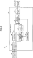
- FIG. 5 is a functional block diagram illustrating the control device 40 according to the present embodiment.
- the control device 40 includes an operation data acquisition unit 41, a control command unit 42, an operating condition determination unit 43, a storage unit 44, a limit command unit 45, an output command determination unit 46, and an output unit 47.
- the operation data acquisition unit 41 acquires, from the operation sensor 20, operation data that is detected by the operation sensor 20 and indicates an operation state of the operating device 7 operated in order to make the bucket 12 perform a dumping movement and a tilting movement.
- the control command unit 42 outputs a control command Ca in order to control the hydraulic device 30 on the basis of the operation data acquired by the operation data acquisition unit 41.
- the control command Ca includes a command value calculated on the basis of the operation amount.
- the operating condition determination unit 43 determines, on the basis of the operation data acquired by the operation data acquisition unit 41, whether the operating device 7 is operated under prescribed operating conditions.
- the prescribed operating conditions include: a first condition in which an operation amount of the operating device 7 to make the bucket 12 perform the dumping movement or the tilting movement is an operation amount threshold value a or more; a second condition in which an operating direction of the operating device 7 is switched prescribed number of times to make the bucket 12 perform the dumping movement and the tilting movement; and a third condition in which an operation time t (t1, t2) of the operating device 7 required to switch the bucket 12 from one movement out of the dumping movement and the tilting movement to the other movement is an operation time threshold value T (Ta, Tb) or less.
- the number of times of switching the operating direction of the operating device 7 represents the number of times operating, in the first operating direction or the second operating direction, the operating device 7 operated in a reciprocating manner between the first operating direction and the second operating direction.
- the number of switching times is once.
- the number of switching times is once.
- the number of switching times is twice.
- the number of switching times is twice.
- the number of switching times is three times.
- the number of switching times is three times.
- the prescribed number of times set as the second condition is a plurality of number of times. In the present embodiment, it is assumed that the prescribed number of times set as the second condition is three times. Note that the prescribed number of times set as the second condition may also be twice or may be arbitrary number of times that is four times or more.
- the storage unit 44 stores the operation amount threshold value a and the operation time threshold value T.
- the operation amount threshold value a and the operation time threshold value T are predetermined values.
- the limit command unit 45 When the operating condition determination unit 43 determines that the operating device 7 is operated under the operating conditions, the limit command unit 45 outputs a limit command Cb to limit the control command Ca.
- the limit command Cb includes a limit value to limit a command value defined by the control command Ca.
- the supply state of the hydraulic fluid supplied to the bucket cylinder 14 includes a flow rate of the hydraulic fluid supplied to the bucket cylinder 14.
- the limit command unit 45 outputs the limit command Cb such that the hydraulic fluid is supplied at a flow rate smaller than a flow rate of the hydraulic fluid supplied to the bucket cylinder 14 on the basis of the control command Ca.
- the limit command unit 45 outputs the limit command Cb such that the bucket cylinder 14 is actuated with a cylinder stroke smaller than a cylinder stroke of the bucket cylinder 14 actuated on the basis of the control command Ca.
- the output command determination unit 46 compares the command value defined by the control command Ca with the limit value defined by the limit command Cb, and determines one of the control command Ca and the limit command Cb as an output command Cc to be output to the hydraulic device 30.
- the output unit 47 outputs, to the hydraulic device 30, the output command Cc determined by the output command determination unit 46.
- the output unit 47 outputs then output command Cc to the control valves 35.
- the output command determination unit 46 determines the limit command Cb as the output command Cc, and in a case where the command value is within the limit value range, the output command determination unit determines the control command Ca as the output command Cc.
- the limit command Cb is output as the output command Cc to be output from the output unit 47 to the control valves 35.
- control command Ca is output as the output command Cc to be output from the output unit 47 to the control valves 35.
- FIGS. 6 and 7 are diagram illustrating an exemplary output command Cc according to the present embodiment.
- a vertical axis represents an operation amount of the operating device 7
- a horizontal axis represents an elapsed time from a reference time point.
- FIG. 6 is a diagram illustrating an output command Cc when the operating device 7 is not operated under the prescribed operating conditions. Meanwhile, FIG. 6(A) illustrates a case where the operating device 7 is operated in a reciprocating manner within a range not reaching the full operation range, and FIG. 6(B) illustrates a case where the operating device 7 is operated in a reciprocating manner in the full operation range but is slowly operated over time.
- each of a line La and a line La' indicated by a solid line indicates detection data of the operation sensor 20.
- the operation amount of the operating device 7 detected by the operation sensor 20 exhibits a positive value.
- the operation amount of the operating device 7 detected by the operation sensor 20 exhibits a negative value.
- FIG. 6 illustrates the state in which the operating device 7 is operated in a reciprocating manner such that the bucket 12 repeats a dumping movement and a tilting movement.
- each of dotted line Lb and the line Lb' indicates the output command Cc.
- the output command Cc is generated slightly more delayed than operation of the operating device 7. Therefore, in FIG. 6 , the line Lb and line Lb' are illustrated in a manner delayed more than the line La and line La' both indicating the detection data of the operation sensor 20. Similarly, in FIG. 7 , a line Lc indicating an output command Cc is illustrated in a manner delayed more than a line La indicating detection data of the operation sensor 20.
- a control command Ca output from the control command unit 42 is output to the control valves 35 as the output command Cc.
- the output command determination unit 46 determines the control command Ca as the output command Cc.
- FIG. 7 is the diagram illustrating the output command Cc when the operating device 7 is operated under the prescribed operating conditions.
- a solid line La indicates detection data of the operation sensor 20. Similar to FIG. 6 , when the operating device 7 is operated in the first operating direction (e.g., forward), the operation amount of the operating device 7 detected by the operation sensor 20 exhibits a positive value. When the operating device 7 is operated in the second operating direction (e.g., backward), the operation amount of the operating device 7 detected by the operation sensor 20 exhibits a negative value.
- a thick broken line Lc indicates the output command Cc.
- the prescribed operating conditions include a condition of satisfying all of the first condition, second condition, and third condition.
- the first condition represents a condition in which the operation amount of the operating device 7 detected by the operation sensor 20 is the operation amount threshold value a or more
- the second condition represents a condition in which the operating direction of the operating device 7 is switched the prescribed number of times to make the bucket 12 perform a dumping movement or a tilting movement.
- the operation amount threshold value a is a value of 90% of a maximum value of the operation amount that can be operated by the operating device 7.
- the second condition represents a condition in which the operation direction of the operating device 7 is switched three times.
- an operation amount at the time of operating the operating device 7 in the first operating direction such that the bucket 12 performs a dumping movement from a reference time point p0 exceeds the operation amount threshold value a.
- An operation amount at the time of operating the operating device 7 in the second operating direction after operating the operating device 7 in the first operating direction such that the bucket 12 performs a tilting movement also exceeds the operation amount threshold value a.
- An operation amount at the time of continuously operating the operating device 7 in the first operating direction after operating the operating device 7 in the second operating direction such that the bucket 12 performs the dumping movement also exceeds the operation amount threshold value a. Therefore, the example illustrated in FIG. 7 satisfies the first condition and the second condition.
- the third condition includes a third condition in which the operation time t (t1, t2) of the operating device 7 required to switch the bucket 12 from one movement out of the dumping movement and the tilting movement to the other movement is less than the operation time threshold value T (Ta, Tb).
- the operation time t includes a first operation time t1 from the time point p1 to the time point p2 and a second operation time t2 from the time point p1 to the control start time point p3.
- An operation time threshold value Ta related to the first operation time t1 is set to 0.25 seconds, for example, and an operation time threshold value Tb related to the second operation time t2 is set to 0.5 seconds, for example.
- the example illustrated in FIG. 7 represents a case where not only the first condition and the second condition but also the third condition are satisfied.
- the example illustrated in FIG. 7 is the case where the operating device 7 is initially operated in the first operating direction, but even in a case where the operating device 7 is initially operated in the second operating direction, when all of the first condition, second condition, and third condition are satisfied, the operating condition determination unit 43 determines that the operating device 7 is operated under the prescribed operating conditions.
- the thick broken line Lc is output to the control valves 35 as the output command Cc until the control start time point p3.
- the limit command unit 45 outputs a limit command until a control finish time point p4 after elapse of a prescribed time from the control start time point p3 at which it is determined that the operating device 7 is operated under the operating conditions.
- a line Ld indicated by a thin broken line represents a limit value defined by a limit command.
- the limit command unit 45 gradually reduces the limit value from the control start time point p3. Since the limit value is gradually reduced, the cylinder stroke of the bucket cylinder 14 becomes gradually small, and a movement amount of the bucket 12 is gradually reduced. Since the movement amount of the bucket 12 is not rapidly reduced, an operator of the wheel loader 1 is suppressed from feeling discomfort about a state that movement of the bucket 12 suddenly becomes non-smooth.
- a minimum limit value b representing a minimum value of the limit value is determined.
- the limit command unit 45 continues outputting the minimum limit value b after the limit value reaches the minimum limit value b.
- the limit command unit 45 continues, without changing the minimum limit value b, outputting the minimum limit value b that is a constant value.
- the limit command unit 45 outputs a limit command Cb until the control finish time point p4 after elapse of a control release preparation time t3 from a release preparation start time point pe indicating a time point at which the operating device 7 is determined to be operated under the prescribed operating conditions last time.
- the release preparation start time point pe is a time point at which preparation for control release based on the limit command Cb is started.
- the control finish time point p4 is a time point at which the control based on the limit command Cb is released.
- the control release preparation time t3 is a period from the release preparation start time point pe to the control finish time point p4, which is a preset time.
- the control finish time point p4 is a time point at which, for example, three seconds elapse as the control release preparation time t3 from the release preparation start time point pe at which the prescribed operating conditions are satisfied last time.
- the release preparation start time point pe is a time point at which an operator of the wheel loader 1 operates the operating device 7 in the first operating direction and the operating condition are satisfied last time. Illustrated is a case where the operation amount does not exceed the operation amount threshold value a and falls in a state not satisfying the first condition despite a fact that the operating device 7 that has been operated in the first operating direction so as to satisfy the operating conditions is operated in the second operating direction after passing the release preparation start time point pe.
- FIG. 7 represents the example in which the bucket 12 that has performed the dumping movement up to the operating limit position at the release preparation start time point pe is operated so as not to be moved to the operating limit position in a next tilting movement.
- control finish time point p4 When the time reaches the control finish time point p4, termination conditions for the control based on the limit command Cb are satisfied, and control returns to the control to extend/contract the bucket cylinder 14 on the basis of the control command Ca. In other words, the control returns to the control to extend/contract the bucket cylinder 14 in accordance with intention of an operator.
- the control based on the limit command Cb is automatically released, and therefore, it is possible to promptly shift to ordinary excavation work or the like.
- the limit value is gradually reduced in the state where the operating device 7 is operated under the prescribed operating conditions, and when the limit value reaches the minimum limit value b, the minimum limit value b is continuously output without changing the minimum limit value b.
- the limit value is gradually reduced at an initial stage of the control based on the limit command Cb, and the minimum limit value b is continuously output to the control valves 35 from the output unit 47.
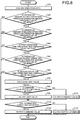
- FIG. 8 is a flowchart illustrating a control method according to the present embodiment.
- the control device 40 repeats processing illustrated in FIG. 8 at a predetermined cycle.
- the operation data acquisition unit 41 acquires operation data from the operation sensor 20 (step S10).
- the operating condition determination unit 43 determines, on the basis of the operation data, whether an operation amount is the operation amount threshold value a or more when the operating device 7 is operated in the first operating direction (step S20).
- step S20 determines, on the basis of the operation data, whether an operation amount is the operation amount threshold value a or more when the operating device 7 is operated in the second operating direction (Step S30).
- step S30 determines, on the basis of the operation data, whether a first operation time t1 of the operating device 7 is equal to or less than 0.25 seconds, namely, an operation time threshold value Ta (step S40).
- step S40 determines, on the basis of the operation data, whether the operation amount is the operation amount threshold value a or more when the operating device 7 is operated in the first operating direction (step S50).
- step S50 determines whether a second operation time t2 of the operating device 7 is equal to or less than 0.5 seconds, namely, an operation time threshold value Tb on the basis of the operation data (step S60).
- step S60 determines that the second operation time t2 is the operation time threshold value Tb or less (step S60: Yes).
- the limit command unit 45 calculates a limit value to limit a command value defined by a control command Ca (Step S70).
- the output command determination unit 46 determines whether a command value output from the control command unit 42 is out of a limit value range (step S80).
- step S80 determines, as an output command Cc, a limit command Cb indicating a limit value.
- the output unit 47 outputs the limit command Cb indicating the limit value as the output command Cc (step S90).
- step S80 determines, as the output command Cc, the control command Ca indicating the command value.
- the output unit 47 outputs the control command Ca indicating the command value as the output command Cc (step S100).
- the output command determination unit 46 determines whether termination conditions for the control based on the above-described limit command Cb are satisfied (step S110).
- step S110 determines whether the termination conditions are not satisfied (step S110: No) or the output command Cc determined in step S100 (step S130), and the processing returns to step S10.
- step S110 determines whether the termination conditions are satisfied (step S110: Yes).
- step S110: Yes the output unit 47 outputs the control command Ca as the output command Cc without changing the magnitude of the control command Ca in order to limit the control command Ca indicating the command value (step S120).
- step S110 In the case where it is determined in step S20 that the operation amount in the first operating direction is not the operation amount threshold value a or more (step S20: No), in the case where it is determined in step S30 that the operation amount in the second operating direction is not the operation amount threshold value a or more (Step S30: No), in the case where it is determined in step S40 that the first operation time t1 is not the operation time threshold value Ta or less (step S40: No), in the case where it is determined in step S50 that the operation amount in the first operating direction is not the operation amount threshold value a or more (step S50: No), and in the case where it is determined that the second operation time t2 is not the operation time threshold value Tb or less (step S60: Yes), the processing in step S110 is executed.
- FIG. 9 is a block diagram illustrating an exemplary computer system 1000.
- the above-described control device 40 includes the computer system 1000.
- the computer system 1000 includes a processor 1001 like a central processing unit (CPU), a main memory 1002 including a nonvolatile memory like a read only memory (ROM) and a volatile memory like a random access memory (RAM), a storage 1003, and an interface 1004 including an input/output interface.
- the above-described functions of the control device 40 are stored in the storage 1003 as a program.
- the processor 1001 reads the program from the storage 1003, develops the program in the main memory 1002, and executes the above-described processing in accordance with the program. Note that the program may also be distributed to the computer system 1000 via a network.
- the limit command unit 45 outputs a limit command Cb to limit a control command Ca output on the basis of the operation data. Consequently, even when the operating device 7 is rapidly operated so as to satisfy the operating conditions, the bucket 12 is suppressed from quickly reciprocating between the operating limit position (stroke end) of the dumping movement and the operating limit position (stroke end) of the tilting movement. Therefore, a load acting on the work machine 10 can be reduced. In other words, even when an operator operates the operating device 7 such that the bucket 12 quickly performs the reciprocating motion between the operating limit position of the dumping movement and the operating limit position of the tilting movement, an excessive load acting on the work machine 10 is automatically suppressed.
- control is executed to limit the cylinder stroke of the bucket cylinder 14 such that the movement of the bucket 12 does not reach the operating limit position of the dumping movement and the operating limit position of the tilting movement.
- the control to limit the cylinder stroke of the bucket cylinder 14 can suppress the operator from feeling discomfort in operating the operating device 7.
- the bucket 12 performs the dumping movement and the tilting movement so as to slow down the operation speed of the operating device 7, and therefore, there is a possibility that the operator feels discomfort.
- the control to limit the cylinder stroke of the bucket cylinder 14 is executed, it is possible to suppress the operator from feeling discomfort in operating the operating device 7.
- a limit command unit 45 may control a movement speed of a dumping movement or a tilting movement to be slowed down.
- a limit command may be generated so as to slow down the movement speed of a bucket 12, and control by which a cylinder speed of a bucket cylinder 14 is limited may also be executed.
- a control device 40 calculates a flow rate of hydraulic fluid supplied per unit time to the bucket cylinder 14 so as to slow down the movement speed of the bucket 12, and the control device generates a limit command on the basis of the calculated flow rate of the hydraulic fluid.
- a work vehicle 1 is assumed to be a wheel loader in the above-described embodiment.
- the work vehicle 1 is provided with a work machine including a work tool like a bucket, and the work vehicle 1 may be at least one of a crawler loader, a dozer excavator, a wheel type excavator, and a crawler type excavator.
- a load acting on the work machine is reduced by controlling a bucket cylinder in accordance with the above-described embodiment.
Landscapes
- Engineering & Computer Science (AREA)
- Mining & Mineral Resources (AREA)
- Civil Engineering (AREA)
- General Engineering & Computer Science (AREA)
- Structural Engineering (AREA)
- Mechanical Engineering (AREA)
- Operation Control Of Excavators (AREA)
Abstract
Description
- The present invention relates to a work vehicle control system and a work vehicle control method. Background
- A work vehicle performs excavating work, loading work, and unloading work of earth and sand by using a bucket of a work machine. For example, when the earth and sand are dumped from a bucket in the loading work, an operator of the work vehicle operates an operating device such that the bucket performs a dumping movement. In a case where the earth and sand remaining after the dumping movement adhere to the bucket, the operator may quickly operate the operating device in a reciprocating manner in a full operation range of the operating device such that the bucket repeats the dumping movement and a tilting movement in order to shake off the earth and sand adhering to the bucket. When the operating device is quickly operated in a reciprocating manner in the full operation range, the bucket performs a reciprocating motion between an operating limit position (stroke end) of the dumping movement and an operating limit position (stroke end) of the tilting movement.
- Patent Literature 1: Japanese Laid-open Patent Publication No.
08-042507 A - Even when an operating device is operated in a reciprocating manner in a full operation range, a large load does not act on a work machine as far as a reciprocating motion of a bucket is slowly repeated over time between an operating limit position of a dumping movement and an operating limit position of a tilting movement. However, when the operating device is quickly operated in a reciprocating manner in the full operation range and the reciprocating motion of the bucket is repeated between the operating limit position of the dumping movement and the operating limit position of the tilting movement in a short period of time, an excessive load is given to at least a part of the work machine at the operating limit position of the dumping movement or the operating limit position of the tilting movement. In such a case, it is necessary to prepare a work machine to which a structure or a material that can withstand the load is applied, thereby causing weight increase or cost increase of the work machine. Additionally, in a case where the work machine cannot withstand the load, the work machine may be damaged.
- An aspect of the present invention is to reduce a load acting on the work machine.
- According to an aspect of the present invention, a work vehicle control system comprises: a hydraulic device configured to adjust a supply state of hydraulic fluid supplied to a hydraulic cylinder configured to cause a work tool to operate; and a control device configured to control the hydraulic device, wherein the control device includes:
an operation data acquisition unit configured to acquire operation data indicating an operation state of an operating device operated in order to cause the work tool to perform a dumping movement and a tilting movement; a control command unit configured to output a control command to control the hydraulic device on the basis of the operation data; an operating condition determination unit configured to determine, on the basis of the operation data, whether the operating device is operated under prescribed operating conditions; and a limit command unit configured to output a limit command to limit the control command in a case where it is determined that the operating device is operated under the operating conditions, wherein the operation data includes; an operation amount of the operating device to cause the work tool to perform the dumping movement or the tilting movement; an operating direction of the operating device to cause the work tool to perform the dumping movement or the tilting movement, and an operation time of the operating device required to switch the work tool from one movement out of the dumping movement and the tilting movement to the other movement, and the operating conditions include: a first condition in which the operation amount is an operation amount threshold value or more; a second condition in which the operation direction is switched prescribed number of times; and a third condition in which the operation time is an operation time threshold value or less. - According to the aspect of the present invention, it is possible to reduce a load acting on the work machine. Brief Description of Drawings
-
-
FIG. 1 is a side view illustrating a work vehicle according to an embodiment. -
FIG. 2 is a diagram schematically illustrating an exemplary control system according to the present embodiment. -
FIG. 3 is a diagram schematically illustrating a flow rate control valve according to the embodiment. -
FIG. 4 is a diagram schematically illustrating exemplary movement of a bucket according to the embodiment. -
FIG. 5 is a functional block diagram illustrating a control device according to the present embodiment. -
FIG. 6 is a diagram to describe a control method according to the embodiment. -
FIG. 7 is a diagram to describe the control method according to the embodiment. -
FIG. 8 is a flowchart illustrating the control method according to the present embodiment. -
FIG. 9 is a block diagram illustrating a computer system according to the embodiment. - An embodiment of the present invention will be described below with reference to the drawings, but the present invention is not limited thereto. Note that constituent elements of the embodiment described below can be suitably combined. Additionally, some of the constituent elements may not be used.
-
FIG. 1 is a side view illustrating awork vehicle 1 according to the present embodiment. In the present embodiment, awork vehicle 1 is awheel loader 1 that is a kind of an articulate work vehicle. Thewheel loader 1 loads, on a hauling vehicle, earth and sand scooped up by abucket 12 serving as a work tool, and unloads the earth and sand in a predetermined place. - As illustrated in
FIG. 1 , thewheel loader 1 includes avehicle body 2, acab 3, a travel device 4, awork machine 10, and acontrol system 50. - The
vehicle body 2 includes a vehiclebody front portion 2F and a vehicle bodyrear portion 2R. Thecab 3 is supported by thevehicle body 2. Anoperating room 3R is provided at thecab 3. Thewheel loader 1 is operated by an operator who boards theoperating room 3R. - The travel device 4 supports the
vehicle body 2. Anarticulation mechanism 9 connects the vehiclebody front portion 2F to the vehicle bodyrear portion 2R in a bendable manner. Thearticulation mechanism 9 includes a steering cylinder. Thevehicle body 2 is bent by extension/contraction of the steering cylinder. Thewheel loader 1 is swung by thevehicle body 2 being bent.Wheels 5 are rotate by power generated by anengine 8 mounted on thevehicle body 2.Tires 6 are respectively attached to thewheels 5. Thewheels 5 include: twofront wheels 5F supported by the vehiclebody front portion 2F; and tworear wheels 5R supported by the vehicle bodyrear portion 2R. Thetires 6 include:front tires 6F attached to thefront wheels 5F; andrear tires 6R attached to therear wheels 5R. With rotation of thewheels 5, thewheel loader 1 travels on ground RS. - The
work machine 10 is supported by the vehiclebody front portion 2F. Thework machine 10 includes a boom 11 connected to thevehicle body 2 in a shakable manner, abucket 12 connected to the boom 11 in a shakable manner, abell crank 15, and abucket link 16. - The boom 11 is vertically shaken by power generated by a
boom cylinder 13. Theboom cylinder 13 is actuated by hydraulic fluid discharged from ahydraulic pump 31. Theboom cylinder 13 is a hydraulic cylinder that vertically shakes the boom 11. One end portion of theboom cylinder 13 is connected to thevehicle body 2. The other end portion of theboom cylinder 13 is connected to the boom 11. - The
bucket 12 is a work tool having adistal end portion 12B including a blade edge. Thebucket 12 is arranged on a more front side than thefront tires 6F are. Thebucket 12 is connected to the distal end portion of the boom 11. Thebucket 12 is shaken by power generated by abucket cylinder 14. Thebucket cylinder 14 is a hydraulic cylinder that shakes thebucket 12. Thebucket cylinder 14 is actuated by hydraulic fluid discharged from ahydraulic pump 31. A center portion of the bell crank 15 is rotatably connected to the boom 11. One end portion of thebucket cylinder 14 is connected to thevehicle body 2. The other end portion of thebucket cylinder 14 is connected to one end portion of thebell crank 15. The other end of the bell crank 15 is connected to thebucket 12 via thebucket link 16. - The
bucket 12 is connected to the distal end portion of the boom 11 via a connectingpin 12P. The one end portion of thebucket cylinder 14 is connected to the vehiclebody front portion 2F via a connecting pin (not illustrated). The other end portion of thebucket cylinder 14 is connected to the one end portion of the bell crank 15 via a connectingpin 15P. The other end portion of the bell crank 15 is connected to one end portion of thebucket link 16 via a connectingpin 15Q. The other end portion of thebucket link 16 is connected to thebucket 12 via a connectingpin 12Q. - A
support member 17 is provided at an intermediate portion of the boom 11. Thesupport member 17 supports thebell crank 15. An intermediate portion of the bell crank 15 is connected to thesupport member 17 via a connectingpin 15R. Thebell crank 15 is rotated using the connectingpin 15R as a fulcrum. - With extension/contraction of the
bucket cylinder 14, the bell crank 15 is rotated using the connectingpin 15R as the fulcrum, and thebucket 12 is rotated using the connectingpin 12P as a fulcrum. An angle of thebucket 12 centering the connectingpin 12P is changed by shaking thebucket 12 using the connectingpin 12P as the fulcrum. In other words, an attitude of thebucket 12 is changed by extension/contraction of thebucket cylinder 14, and thebucket 12 performs a dumping movement or a tilting movement. - When the
bucket cylinder 14 is contracted, the bell crank 15 is rotated using the connectingpin 15R as the fulcrum such that the one end portion of the bell crank 15 is moved rearward and the other end portion of the bell crank 15 is moved forward. When the other end of the bell crank 15 is moved forward, thebucket 12 is pushed forward by thebucket link 16. Thebucket 12 performs a dumping movement by thebucket 12 being pushed forward by thebucket link 16. - When the
bucket cylinder 14 is extended, the bell crank 15 is rotated using the connectingpin 15R as the fulcrum such that the one end portion of the bell crank 15 is moved forward and the other end of the bell crank 15 is moved rearward. When the other end of the bell crank 15 is moved rearward, thebucket 12 is pulled rearward by thebucket link 16. Thebucket 12 performs a tilting movement by thebucket 12 being pulled rearward by thebucket link 16. - The dumping movement of the
bucket 12 represents a movement in which thebucket 12 is rotated using the connectingpin 12P as the fulcrum such that an openedportion 12M of thebucket 12 faces downward and thedistal end portion 12B is moved close to the ground RS. The tilting movement of thebucket 12 represents operation in which thebucket 12 is rotated using the connectingpin 12P as the fulcrum such that the openedportion 12M faces upward and thedistal end portion 12B is moved away from the ground RS. With execution of the dumping movement of thebucket 12, the earth and sand scooped up by thebucket 12 is unloaded from thebucket 12. With execution of the tilting movement of thebucket 12, thebucket 12 scoops up the earth and sand. - The
operating room 3R is provided with: an operator's seat on which an operator is seated; and anoperating device 7 operated by the operator. The operatingdevice 7 includes an accelerator pedal, a brake pedal, a steering lever, a forward/backward travel changeover switch, and a work machine operating lever. - An operator can perform changeover between driving, braking, swinging, and forward/backward traveling of the travel device 4 by operating the accelerator pedal, brake pedal, steering lever, and forward/backward travel changeover switch of the
operating device 7. - The operator can perform driving, braking, and adjustment of a travel speed of the travel device 4 by operating the accelerator pedal and brake pedal of the
operating device 7. The operator can swing thewheel loader 1 by operating the steering lever of theoperating device 7 and can perform changeover between forward and backward traveling of thewheel loader 1 by operating a forward/backward changeover lever. - The operator can actuate the
boom cylinder 13 and thebucket cylinder 14 by operating the work machine operating lever of theoperating device 7. The boom 11 performs a lifting movement or a lowering movement by extension/contraction of theboom cylinder 13. Thebucket 12 performs a tilting movement or a dumping movement by extension/contraction of thebucket cylinder 14. -
FIG. 2 is a diagram schematically illustrating anexemplary control system 50 according to the present embodiment. Thecontrol system 50 is mounted on thewheel loader 1. Thecontrol system 50 includes: ahydraulic device 30 that adjusts a supply state of the hydraulic fluid supplied to each of theboom cylinder 13 andbucket cylinder 14; and acontrol device 40 that controls thehydraulic device 30. Thehydraulic device 30 illustrated inFIG. 2 adjusts the supply state of the hydraulic fluid supplied to thebucket cylinder 14 that makes thebucket 12 perform a movement. Thecontrol device 40 includes a computer system. The supply state of the hydraulic fluid includes at least one of: a state of increasing/decreasing a flow rate of the hydraulic fluid supplied in order to extend or contract thebucket cylinder 14 up to an operating limit position (stroke end); and a state of increasing/ decreasing a flow rate of the hydraulic fluid supplied per unit time in order to extend or contract thebucket cylinder 14 up to the operating limit position (stroke end). - The
hydraulic device 30 includes: thehydraulic pump 31 to supply the hydraulic fluid; ahydraulic pump 32 to supply pilot oil;oil passages FIG. 3 ), and further includes: a flowrate control valve 34 to adjust a flow rate and a direction of the hydraulic fluid supplied to thebucket cylinder 14 by movement of thespur 38; and control valves 35 (control valves spur 38. A pilot pressure acts on the flowrate control valve 34 by the pilot oil flowing through theoil passages spur 38 is the pilot pressure. Thecontrol valves spur 38. - The pilot oil discharged from the
hydraulic pump 32 is supplied to theoperating device 7. Note that the pilot oil that is discharged from thehydraulic pump 31 and has the pressure reduced by a pressure reducing valve may also be supplied to theoperating device 7. The operatingdevice 7 includes a pilot pressure regulating valve like a rotary valve. The pilot oil discharged from thehydraulic pump 32 is supplied to the flowrate control valve 34 via theoperating device 7 and theoil passages - The
bucket cylinder 14 has a piston-side oil chamber 14A and a rod-side oil chamber 14B. The hydraulic fluid discharged from thehydraulic pump 31 is supplied to thebucket cylinder 14 via the flowrate control valve 34. When the hydraulic fluid is supplied to the piston-side oil chamber 14A via aport 37A of the flowrate control valve 34 and anoil passage 36A, thebucket cylinder 14 is extended. When the hydraulic fluid is supplied to the rod-side oil chamber 14B via aport 37B of the flowrate control valve 34 and anoil passage 36B, thebucket cylinder 14 is contracted. - The operating
device 7 includes the work machine operating lever, and the work machine operation lever is operated by an operator in order to make thebucket 12 perform a dumping movement and a tilting movement. When the work machine operating lever of theoperating device 7 is operated so as to be fall down in a first operating direction (e.g., forward), thebucket cylinder 14 is contracted and thebucket 12 performs the dumping movement. When the work machine operating lever of theoperating device 7 is operated so as to fall down in a second operating direction (e.g., backward), thebucket cylinder 14 is extended and thebucket 12 performs the tilting movement. - Additionally, when the work machine operating lever of the
operating device 7 is operated in the first operating direction, a cylinder stroke indicating a contraction amount of thebucket cylinder 14 is changed on the basis of an operation amount of the work machine operating lever of theoperating device 7, and a rotation angle of thebucket 12 performing the dumping movement is changed. For example, when the work machine operating lever of theoperating device 7 is operated with a large operation amount in the first operating direction, thebucket cylinder 14 is actuated with a large cylinder stroke, and the rotation angle of thebucket 12 performing the dumping movement is increased. When the work machine operating lever of theoperating device 7 is operated with a small operation amount in the first operating direction, thebucket cylinder 14 is actuated with a small cylinder stroke, and the rotation angle of thebucket 12 performing the dumping movement is reduced. - Similarly, when the work machine operating lever of the
operating device 7 is operated in the second operating direction, the cylinder stroke of thebucket cylinder 14 is changed on the basis of the operation amount of the work machine operating lever, and the rotation angle of thebucket 12 performing a tilting movement is changed. - Additionally, when the work machine operating lever of the
operating device 7 is operated in the first operating direction, a cylinder speed of thebucket cylinder 14 is changed on the basis of an operation speed of the work machine operating lever, and a movement speed (rotation speed) of thebucket 12 performing the dumping movement is changed. For example, when the work machine operating lever of theoperating device 7 is operated at a high operation speed in the first operating direction, thebucket cylinder 14 is actuated at a high cylinder speed and the movement speed of thebucket 12 performing the dumping movement becomes fast. When the work machine operating lever of theoperating device 7 is operated at a low operation speed in the first operating direction, thebucket cylinder 14 is actuated at a low cylinder speed and the movement speed of thebucket 12 performing the dumping movement becomes slow. - Similarly, when the work machine operating lever of the
operating device 7 is operated in the second operating direction, the cylinder speed of thebucket cylinder 14 is changed on the basis of the operation speed of the work machine operating lever, and the movement speed of thebucket 12 performing a tilting movement is changed. - The
control system 50 includes anoperation sensor 20 that detects operation data indicating an operation state of theoperating device 7. Theoperation sensor 20 includes, for example, a potentiometer. Theoperation sensor 20 is provided in theoperating device 7. - The operation data detected by the
operation sensor 20 includes: an operation amount of theoperating device 7 to make thebucket 12 perform a dumping movement or a tilting movement; an operating direction of theoperating device 7 to make thebucket 12 perform the dumping movement or the tilting movement; and an operation time and an operation speed of theoperating device 7 at the time of switching thebucket 12 from one movement out of the dumping movement and the tilting movement to the other movement. The operation data detected by theoperation sensor 20 is output to thecontrol device 40. - The
control device 40 controls thecontrol valves operation sensor 20. The pilot pressure acting on the flowrate control valve 34 is adjusted by controlling thecontrol valves device 7, a moving amount, a moving speed, and a moving direction of thespur 38 in an axial direction are adjusted. Consequently, the supply state of the hydraulic fluid supplied to thebucket cylinder 14 is adjusted. -
FIG. 3 is a diagram schematically illustrating the flowrate control valve 34 according to the present embodiment. The flowrate control valve 34 is a slide spur type flow rate control valve that switches a flow rate and a direction of the hydraulic fluid supplied to thebucket cylinder 14 by moving the rod-shapedspur 38 in the axial direction. Supply of the hydraulic fluid to the piston-side oil chamber 14A and supply of the hydraulic fluid to the rod-side oil chamber 14B are switched by moving thespur 38 in the axial direction. As illustrated inFIG. 3(A) , when thespur 38 is moved to one side in the axial direction, a flow path indicated by a broken line arrow is formed, and the hydraulic fluid is discharged from theport 37A. The hydraulic fluid discharged from theport 37A is supplied to the piston-side oil chamber 14A. As illustrated inFIG. 3(B) , when thespur 38 is moved to the other side in the axial direction, a flow path indicated by a broken line arrow is formed, and the hydraulic fluid is discharged from theport 37B. The hydraulic fluid discharged from theport 37B is supplied to the rod-side oil chamber 14B. - In other words, with movement of the
spur 38 in the axial direction, an actuation direction of thebucket cylinder 14 is adjusted. A movement direction of thebucket 12 is adjusted by adjusting the actuation direction of thebucket cylinder 14. The movement direction of thebucket 12 includes: a first movement direction in which thebucket 12 performs a tilting movement; and a second movement direction in which thebucket 12 performs a dumping movement. Thebucket 12 is moved in the first movement direction and performs the tilting movement by operating theoperating device 7 in the first operating direction and supplying the hydraulic fluid to the piston-side oil chamber 14A of thebucket cylinder 14 to extend thebucket cylinder 14. Thebucket 12 is moved in the second movement direction and performs the dumping movement by operating theoperating device 7 in the second operating direction and supplying the hydraulic fluid to the rod-side oil chamber 14B of thebucket cylinder 14 to contract thebucket cylinder 14. - Additionally, the flow rate of the hydraulic fluid supplied to the
bucket cylinder 14 per unit time is adjusted by movement of thespur 38 in the axial direction. The cylinder stroke or the cylinder speed of thebucket cylinder 14 is adjusted by adjusting the flow rate of the hydraulic fluid of the hydraulic fluid supplied to thebucket cylinder 14. The rotation angle or the movement speed of thebucket 12 is adjusted by adjusting the cylinder stroke or the cylinder speed of thebucket cylinder 14. The rotation angle of thebucket 12 indicates a shaking amount of thebucket 12, and the movement speed of thebucket 12 indicates the rotation speed (shaking speed) of thebucket 12. - Note that the
operating device 7 is not necessarily the pilot pressure type. The operatingdevice 7 may be an electronic lever type in which operation data detected by theoperation sensor 20 is output to thecontrol device 40 and a flow rate control valve 24 is electrically controlled on the basis of thecontrol device 40. -
FIG. 4 is a diagram schematically illustrating exemplary movement of thebucket 12 according to the present embodiment. Thewheel loader 1 executes loading work to load earth and sand on a loading platform of adump truck 100 by using thebucket 12 of thework machine 10. An operator of thewheel loader 1 operates theoperating device 7 such that thebucket 12 performs a dumping movement at the time of unloading the earth and sand from thebucket 12. When remaining earth and sand adhere to thebucket 12 even after execution of the dumping movement, the operator may quickly operate theoperating device 7 in a reciprocating manner in a full operation range of theoperating device 7 such that thebucket 12 repeats a dumping movement and a tilting movement in order to shake off the earth and sand adhering to thebucket 12. - When the
operating device 7 is quickly operated in a reciprocating manner in the full operation range, thebucket cylinder 14 quickly repeats an extended state up to an operating limit position (stroke end) and a contracted state up to an operating limit position (stroke end), and thebucket 12 performs a reciprocating motion between the operating limit position (stroke end) of the dumping movement and the operating limit position (stroke end) of the tilting movement. When such a reciprocating motion of the bucket is repeated between the operating limit position of the dumping movement and the operating limit position of the tilting movement in a short period of time, an excessive load may be given to at least a part of thework machine 10 at the operating limit position of the dumping movement or the operating limit position of the tilting movement. For example, there is a possibility that excessive stress acts on thesupport member 17 connected to the bell crank 15 via the connectingpin 15R, or excessive stress acts on thebell crank 15. When the excessive load is given to a part of thework machine 10, thework machine 10 may be damaged. In a case of preparing thework machine 10 in which a structure or a material that can withstand the load is applied, and weight increase or cost increase of thework machine 10 is caused. - In the following description, operation of the
operating device 7 executed by an operator such that thebucket 12 quickly performs the reciprocating motion between the operating limit position of the dumping movement and the operating limit position of the tilting movement will be referred to as rapid operation as appropriate. - As described above, in the case of shaking off the earth and sand adhering to the
bucket 12, an operator may rapidly repeat the dumping movement and the tilting movement of thebucket 12 by executing the rapid operation of theoperating device 7 in the full operation range. - In the present embodiment, even in the case where the operator executes the rapid operation of the
operating device 7, thecontrol device 40 controls thecontrol valves 35 such that thebucket 12 does not reach the operating limit position (stroke end) of the dumping movement and does not reach the operating limit position (stroke end) of the tilting movement in the dumping movement and the tilting movement of thebucket 12. In other words, when theoperating device 7 is rapidly operated, thecontrol device 40 controls the movement of thebucket 12 such that an excessive load is not given to at least a part of thework machine 10. -
FIG. 5 is a functional block diagram illustrating thecontrol device 40 according to the present embodiment. As illustrated inFIG. 5 , thecontrol device 40 includes an operation data acquisition unit 41, acontrol command unit 42, an operating condition determination unit 43, a storage unit 44, alimit command unit 45, an outputcommand determination unit 46, and an output unit 47. - The operation data acquisition unit 41 acquires, from the
operation sensor 20, operation data that is detected by theoperation sensor 20 and indicates an operation state of theoperating device 7 operated in order to make thebucket 12 perform a dumping movement and a tilting movement. - The
control command unit 42 outputs a control command Ca in order to control thehydraulic device 30 on the basis of the operation data acquired by the operation data acquisition unit 41. The control command Ca includes a command value calculated on the basis of the operation amount. - The operating condition determination unit 43 determines, on the basis of the operation data acquired by the operation data acquisition unit 41, whether the operating
device 7 is operated under prescribed operating conditions. - The prescribed operating conditions include: a first condition in which an operation amount of the
operating device 7 to make thebucket 12 perform the dumping movement or the tilting movement is an operation amount threshold value a or more; a second condition in which an operating direction of theoperating device 7 is switched prescribed number of times to make thebucket 12 perform the dumping movement and the tilting movement; and a third condition in which an operation time t (t1, t2) of theoperating device 7 required to switch thebucket 12 from one movement out of the dumping movement and the tilting movement to the other movement is an operation time threshold value T (Ta, Tb) or less. - In the second condition, the number of times of switching the operating direction of the
operating device 7 represents the number of times operating, in the first operating direction or the second operating direction, the operatingdevice 7 operated in a reciprocating manner between the first operating direction and the second operating direction. When theoperating device 7 currently operated to be a neutral state or in the second operating direction is operated in the first operating direction once, the number of switching times is once. When theoperating device 7 currently operated to be the neutral state or in the first operating direction is operated in the second operating direction once, the number of switching times is once. When theoperating device 7 currently operated to be the neutral state or in the second operating direction is operated in the second operating direction after being operated in the first operating direction, the number of switching times is twice. When theoperating device 7 currently operated to be the neutral state or in the first operating direction is operated in the first direction after being operated in the second operating direction, the number of switching times is twice. When theoperating device 7 currently operated to be the neutral state or in the second operating direction is operated in the first operating direction, subsequently operated in the second operating direction, and then operated in the first operating direction again, the number of switching times is three times. When theoperating device 7 currently operated to be the neutral state or in the first operating direction is operated in the second operating direction, subsequently operated in the first direction, and then operated in the second operating direction again, the number of switching times is three times. - The prescribed number of times set as the second condition is a plurality of number of times. In the present embodiment, it is assumed that the prescribed number of times set as the second condition is three times. Note that the prescribed number of times set as the second condition may also be twice or may be arbitrary number of times that is four times or more.
- The storage unit 44 stores the operation amount threshold value a and the operation time threshold value T. The operation amount threshold value a and the operation time threshold value T are predetermined values.
- When the operating condition determination unit 43 determines that the
operating device 7 is operated under the operating conditions, thelimit command unit 45 outputs a limit command Cb to limit the control command Ca. The limit command Cb includes a limit value to limit a command value defined by the control command Ca. - The supply state of the hydraulic fluid supplied to the
bucket cylinder 14 includes a flow rate of the hydraulic fluid supplied to thebucket cylinder 14. Thelimit command unit 45 outputs the limit command Cb such that the hydraulic fluid is supplied at a flow rate smaller than a flow rate of the hydraulic fluid supplied to thebucket cylinder 14 on the basis of the control command Ca. In other words, thelimit command unit 45 outputs the limit command Cb such that thebucket cylinder 14 is actuated with a cylinder stroke smaller than a cylinder stroke of thebucket cylinder 14 actuated on the basis of the control command Ca. - The output
command determination unit 46 compares the command value defined by the control command Ca with the limit value defined by the limit command Cb, and determines one of the control command Ca and the limit command Cb as an output command Cc to be output to thehydraulic device 30. - The output unit 47 outputs, to the
hydraulic device 30, the output command Cc determined by the outputcommand determination unit 46. The output unit 47 outputs then output command Cc to thecontrol valves 35. - In a case where a command value is out of a limit value range, the output
command determination unit 46 determines the limit command Cb as the output command Cc, and in a case where the command value is within the limit value range, the output command determination unit determines the control command Ca as the output command Cc. In other words, in a case where a command value is out of the limit value range by comparing the command value defined by the control command Ca with the limit value defined by the limit command Cb, the limit command Cb is output as the output command Cc to be output from the output unit 47 to thecontrol valves 35. In a case where a command value is within the limit value range by comparing the command value defined by the control command Ca with the limit value defined by the limit command Cb, the control command Ca is output as the output command Cc to be output from the output unit 47 to thecontrol valves 35. - Each of
FIGS. 6 and7 is a diagram illustrating an exemplary output command Cc according to the present embodiment. In each ofFIGS. 6 and7 , a vertical axis represents an operation amount of theoperating device 7, and a horizontal axis represents an elapsed time from a reference time point. -
FIG. 6 is a diagram illustrating an output command Cc when theoperating device 7 is not operated under the prescribed operating conditions. Meanwhile,FIG. 6(A) illustrates a case where theoperating device 7 is operated in a reciprocating manner within a range not reaching the full operation range, andFIG. 6(B) illustrates a case where theoperating device 7 is operated in a reciprocating manner in the full operation range but is slowly operated over time. - In
FIG. 6 , each of a line La and a line La' indicated by a solid line indicates detection data of theoperation sensor 20. When theoperating device 7 is operated in the first operating direction (e.g., forward), the operation amount of theoperating device 7 detected by theoperation sensor 20 exhibits a positive value. When theoperating device 7 is operated in the second operating direction (e.g., backward), the operation amount of theoperating device 7 detected by theoperation sensor 20 exhibits a negative value. In other words,FIG. 6 illustrates the state in which theoperating device 7 is operated in a reciprocating manner such that thebucket 12 repeats a dumping movement and a tilting movement. - In
FIG. 6 , each of dotted line Lb and the line Lb' indicates the output command Cc. The output command Cc is generated slightly more delayed than operation of theoperating device 7. Therefore, inFIG. 6 , the line Lb and line Lb' are illustrated in a manner delayed more than the line La and line La' both indicating the detection data of theoperation sensor 20. Similarly, inFIG. 7 , a line Lc indicating an output command Cc is illustrated in a manner delayed more than a line La indicating detection data of theoperation sensor 20. - When the
operating device 7 is not operated under the prescribed operating conditions, a control command Ca output from thecontrol command unit 42 is output to thecontrol valves 35 as the output command Cc. - In other words, in a case where it is not determined that the
operating device 7 is operated under the operating conditions, the outputcommand determination unit 46 determines the control command Ca as the output command Cc. -
FIG. 7 is the diagram illustrating the output command Cc when theoperating device 7 is operated under the prescribed operating conditions. InFIG. 7 , a solid line La indicates detection data of theoperation sensor 20. Similar toFIG. 6 , when theoperating device 7 is operated in the first operating direction (e.g., forward), the operation amount of theoperating device 7 detected by theoperation sensor 20 exhibits a positive value. When theoperating device 7 is operated in the second operating direction (e.g., backward), the operation amount of theoperating device 7 detected by theoperation sensor 20 exhibits a negative value. - A thick broken line Lc indicates the output command Cc. When the
operating device 7 is operated under the prescribed operating conditions, a control command Ca output from thecontrol command unit 42 is limited by thelimit command unit 45 as a limit command Cb, and the limit command Cb is output as the output command Cc to thecontrol valves 35. - The prescribed operating conditions include a condition of satisfying all of the first condition, second condition, and third condition.
- The first condition represents a condition in which the operation amount of the
operating device 7 detected by theoperation sensor 20 is the operation amount threshold value a or more The second condition represents a condition in which the operating direction of theoperating device 7 is switched the prescribed number of times to make thebucket 12 perform a dumping movement or a tilting movement. In the present embodiment, the operation amount threshold value a is a value of 90% of a maximum value of the operation amount that can be operated by the operatingdevice 7. In the present embodiment, the second condition represents a condition in which the operation direction of theoperating device 7 is switched three times. - In the example illustrated in
FIG. 7 , an operation amount at the time of operating theoperating device 7 in the first operating direction such that thebucket 12 performs a dumping movement from a reference time point p0 exceeds the operation amount threshold value a. An operation amount at the time of operating theoperating device 7 in the second operating direction after operating theoperating device 7 in the first operating direction such that thebucket 12 performs a tilting movement also exceeds the operation amount threshold value a. An operation amount at the time of continuously operating theoperating device 7 in the first operating direction after operating theoperating device 7 in the second operating direction such that thebucket 12 performs the dumping movement also exceeds the operation amount threshold value a. Therefore, the example illustrated inFIG. 7 satisfies the first condition and the second condition. - The third condition includes a third condition in which the operation time t (t1, t2) of the
operating device 7 required to switch thebucket 12 from one movement out of the dumping movement and the tilting movement to the other movement is less than the operation time threshold value T (Ta, Tb). When a time point at which the operation mount exceeds the operation amount threshold value a at the time of operating theoperating device 7 in the first operating direction is defined as p1, and a time point at which the operation amount exceeds the operation amount threshold value a at the time of continuously operating theoperating device 7 in the second operating direction is defined as p2, and a time point (control start time point) at which an operation amount exceeds the operation amount threshold value a at the time of continuously operating the operating device in the first operating direction is defined as p3, the operation time t includes a first operation time t1 from the time point p1 to the time point p2 and a second operation time t2 from the time point p1 to the control start time point p3. An operation time threshold value Ta related to the first operation time t1 is set to 0.25 seconds, for example, and an operation time threshold value Tb related to the second operation time t2 is set to 0.5 seconds, for example. The example illustrated inFIG. 7 represents a case where not only the first condition and the second condition but also the third condition are satisfied. - Meanwhile, the example illustrated in
FIG. 7 is the case where theoperating device 7 is initially operated in the first operating direction, but even in a case where theoperating device 7 is initially operated in the second operating direction, when all of the first condition, second condition, and third condition are satisfied, the operating condition determination unit 43 determines that theoperating device 7 is operated under the prescribed operating conditions. - The thick broken line Lc is output to the
control valves 35 as the output command Cc until the control start time point p3. Thelimit command unit 45 outputs a limit command until a control finish time point p4 after elapse of a prescribed time from the control start time point p3 at which it is determined that theoperating device 7 is operated under the operating conditions. A line Ld indicated by a thin broken line represents a limit value defined by a limit command. As indicated by the line Ld, thelimit command unit 45 gradually reduces the limit value from the control start time point p3. Since the limit value is gradually reduced, the cylinder stroke of thebucket cylinder 14 becomes gradually small, and a movement amount of thebucket 12 is gradually reduced. Since the movement amount of thebucket 12 is not rapidly reduced, an operator of thewheel loader 1 is suppressed from feeling discomfort about a state that movement of thebucket 12 suddenly becomes non-smooth. - In the present embodiment, a minimum limit value b representing a minimum value of the limit value is determined. As indicated by the line Ld in
FIG. 7 , thelimit command unit 45 continues outputting the minimum limit value b after the limit value reaches the minimum limit value b. Thelimit command unit 45 continues, without changing the minimum limit value b, outputting the minimum limit value b that is a constant value. - The
limit command unit 45 outputs a limit command Cb until the control finish time point p4 after elapse of a control release preparation time t3 from a release preparation start time point pe indicating a time point at which theoperating device 7 is determined to be operated under the prescribed operating conditions last time. - The release preparation start time point pe is a time point at which preparation for control release based on the limit command Cb is started. The control finish time point p4 is a time point at which the control based on the limit command Cb is released. The control release preparation time t3 is a period from the release preparation start time point pe to the control finish time point p4, which is a preset time.
- In the present embodiment, the control finish time point p4 is a time point at which, for example, three seconds elapse as the control release preparation time t3 from the release preparation start time point pe at which the prescribed operating conditions are satisfied last time. In the example illustrated in
FIG. 7 , the release preparation start time point pe is a time point at which an operator of thewheel loader 1 operates theoperating device 7 in the first operating direction and the operating condition are satisfied last time. Illustrated is a case where the operation amount does not exceed the operation amount threshold value a and falls in a state not satisfying the first condition despite a fact that theoperating device 7 that has been operated in the first operating direction so as to satisfy the operating conditions is operated in the second operating direction after passing the release preparation start time point pe. In other words,FIG. 7 represents the example in which thebucket 12 that has performed the dumping movement up to the operating limit position at the release preparation start time point pe is operated so as not to be moved to the operating limit position in a next tilting movement. - When the time reaches the control finish time point p4, termination conditions for the control based on the limit command Cb are satisfied, and control returns to the control to extend/contract the
bucket cylinder 14 on the basis of the control command Ca. In other words, the control returns to the control to extend/contract thebucket cylinder 14 in accordance with intention of an operator. When the operator stops the rapid operation, the control based on the limit command Cb is automatically released, and therefore, it is possible to promptly shift to ordinary excavation work or the like. - In the present embodiment, the limit value is gradually reduced in the state where the
operating device 7 is operated under the prescribed operating conditions, and when the limit value reaches the minimum limit value b, the minimum limit value b is continuously output without changing the minimum limit value b. In a case where theoperating device 7 is continuously operated for a long time so as to satisfy the prescribed operating conditions, the limit value is gradually reduced at an initial stage of the control based on the limit command Cb, and the minimum limit value b is continuously output to thecontrol valves 35 from the output unit 47. -
FIG. 8 is a flowchart illustrating a control method according to the present embodiment. Thecontrol device 40 repeats processing illustrated inFIG. 8 at a predetermined cycle. - The operation data acquisition unit 41 acquires operation data from the operation sensor 20 (step S10).
- The operating condition determination unit 43 determines, on the basis of the operation data, whether an operation amount is the operation amount threshold value a or more when the
operating device 7 is operated in the first operating direction (step S20). - In a case where it is determined in step S20 that the operation amount is the operation amount threshold value a or more (step S20: Yes), the operating condition determination unit 43 determines, on the basis of the operation data, whether an operation amount is the operation amount threshold value a or more when the
operating device 7 is operated in the second operating direction (Step S30). - In a case where it is determined in step S30 that the operation amount is the operation amount threshold value a or more (step S30: Yes), the operating condition determination unit 43 determines, on the basis of the operation data, whether a first operation time t1 of the
operating device 7 is equal to or less than 0.25 seconds, namely, an operation time threshold value Ta (step S40). - In a case where it is determined in step S40 that the first operation time t1 is the operation time threshold value Ta or less (step S40: Yes), the
operation sensor 20 detects that theoperating device 7 is operated, and the operation data acquisition unit 41 acquires operation data. The operating condition determination unit 43 determines, on the basis of the operation data, whether the operation amount is the operation amount threshold value a or more when theoperating device 7 is operated in the first operating direction (step S50). - In a case where it is determined in step S50 that the operation amount is the operation amount threshold value a or more (step S50: Yes), the operating condition determination unit 43 determines whether a second operation time t2 of the
operating device 7 is equal to or less than 0.5 seconds, namely, an operation time threshold value Tb on the basis of the operation data (step S60). - In a case where it is determined in step S60 that the second operation time t2 is the operation time threshold value Tb or less (step S60: Yes), the
limit command unit 45 calculates a limit value to limit a command value defined by a control command Ca (Step S70). - The output
command determination unit 46 determines whether a command value output from thecontrol command unit 42 is out of a limit value range (step S80). - In a case where it is determined in step S80 that the command value is out of the limit value range (step S80: Yes), the output
command determination unit 46 determines, as an output command Cc, a limit command Cb indicating a limit value. The output unit 47 outputs the limit command Cb indicating the limit value as the output command Cc (step S90). - In a case where it is determined in step S80 that the command value is within the limit value range (step S80: No), the output
command determination unit 46 determines, as the output command Cc, the control command Ca indicating the command value. The output unit 47 outputs the control command Ca indicating the command value as the output command Cc (step S100). - The output
command determination unit 46 determines whether termination conditions for the control based on the above-described limit command Cb are satisfied (step S110). - In a case where it is determined in step S110 that the termination conditions are not satisfied (step S110: No), the output unit 47 outputs the output command Cc determined in step S90 or the output command Cc determined in step S100 (step S130), and the processing returns to step S10.
- In a case where it is determined in step S110 that the termination conditions are satisfied (step S110: Yes), the output unit 47 outputs the control command Ca as the output command Cc without changing the magnitude of the control command Ca in order to limit the control command Ca indicating the command value (step S120).
- In the case where it is determined in step S20 that the operation amount in the first operating direction is not the operation amount threshold value a or more (step S20: No), in the case where it is determined in step S30 that the operation amount in the second operating direction is not the operation amount threshold value a or more (Step S30: No), in the case where it is determined in step S40 that the first operation time t1 is not the operation time threshold value Ta or less (step S40: No), in the case where it is determined in step S50 that the operation amount in the first operating direction is not the operation amount threshold value a or more (step S50: No), and in the case where it is determined that the second operation time t2 is not the operation time threshold value Tb or less (step S60: Yes), the processing in step S110 is executed.
-
FIG. 9 is a block diagram illustrating anexemplary computer system 1000. The above-describedcontrol device 40 includes thecomputer system 1000. Thecomputer system 1000 includes aprocessor 1001 like a central processing unit (CPU), amain memory 1002 including a nonvolatile memory like a read only memory (ROM) and a volatile memory like a random access memory (RAM), astorage 1003, and aninterface 1004 including an input/output interface. The above-described functions of thecontrol device 40 are stored in thestorage 1003 as a program. Theprocessor 1001 reads the program from thestorage 1003, develops the program in themain memory 1002, and executes the above-described processing in accordance with the program. Note that the program may also be distributed to thecomputer system 1000 via a network. - As described above, according to the present embodiment, in a case where the
operating device 7 is quickly operated such that thebucket 12 repeats a dumping movement and a tilting movement, that is, in a case where theoperating device 7 is operated such that operation data satisfy the operating conditions, thelimit command unit 45 outputs a limit command Cb to limit a control command Ca output on the basis of the operation data. Consequently, even when theoperating device 7 is rapidly operated so as to satisfy the operating conditions, thebucket 12 is suppressed from quickly reciprocating between the operating limit position (stroke end) of the dumping movement and the operating limit position (stroke end) of the tilting movement. Therefore, a load acting on thework machine 10 can be reduced. In other words, even when an operator operates theoperating device 7 such that thebucket 12 quickly performs the reciprocating motion between the operating limit position of the dumping movement and the operating limit position of the tilting movement, an excessive load acting on thework machine 10 is automatically suppressed. - In the present embodiment, in the case where the
operating device 7 is quickly operated in the full operation range such thebucket 12 quickly performs the reciprocating motion between the operating limit position of the dumping movement and the operating limit position of the tilting movement, in other words, such that the operation data satisfies the operating conditions, control is executed to limit the cylinder stroke of thebucket cylinder 14 such that the movement of thebucket 12 does not reach the operating limit position of the dumping movement and the operating limit position of the tilting movement. The control to limit the cylinder stroke of thebucket cylinder 14 can suppress the operator from feeling discomfort in operating theoperating device 7. For example, in the case where the movement speed of thebucket 12 is controlled to be slowed down by limiting the cylinder speed of thebucket cylinder 14 in order to suppress the excessive load from acting on thework machine 10, thebucket 12 performs the dumping movement and the tilting movement so as to slow down the operation speed of theoperating device 7, and therefore, there is a possibility that the operator feels discomfort. According to the present embodiment, since the control to limit the cylinder stroke of thebucket cylinder 14 is executed, it is possible to suppress the operator from feeling discomfort in operating theoperating device 7. - Meanwhile, in an embodiment described above, in a case where an
operating device 7 is quickly operated in a full operation range such that operation data satisfies operating conditions, alimit command unit 45 may control a movement speed of a dumping movement or a tilting movement to be slowed down. In other words, in a case where the operation data satisfies the operating conditions, a limit command may be generated so as to slow down the movement speed of abucket 12, and control by which a cylinder speed of abucket cylinder 14 is limited may also be executed. - In the case of slowing down the movement speed of the
bucket 12, acontrol device 40 calculates a flow rate of hydraulic fluid supplied per unit time to thebucket cylinder 14 so as to slow down the movement speed of thebucket 12, and the control device generates a limit command on the basis of the calculated flow rate of the hydraulic fluid. - Note that a
work vehicle 1 is assumed to be a wheel loader in the above-described embodiment. As far as thework vehicle 1 is provided with a work machine including a work tool like a bucket, and thework vehicle 1 may be at least one of a crawler loader, a dozer excavator, a wheel type excavator, and a crawler type excavator. For example, in a case where thework vehicle 1 is an excavator, when an operating device of the excavator is quickly operated in a reciprocating manner in a full operation range such that a bucket that is a work tool quickly performs a reciprocating motion between an operating limit position of a dumping movement and an operating limit position of a tilting movement, a load acting on the work machine is reduced by controlling a bucket cylinder in accordance with the above-described embodiment. -
- 1
- WHEEL LOADER (WORK VEHICLE)
- 2
- VEHICLE BODY
- 2F
- VEHICLE BODY FRONT PORTION
- 2R
- VEHICLE BODY REAR PORTION
- 3
- CAB
- 3R
- OPERATING ROOM
- 4
- TRAVEL DEVICE
- 5
- WHEEL
- 5F
- FRONT WHEEL
- 5R
- REAR WHEEL
- 6
- TIRE
- 6F
- FRONT TIRE
- 6R
- REAR TIRE
- 7
- OPERATING DEVICE
- 8
- ENGINE
- 9
- ARTICULATION MECHANISM
- 10
- WORK MACHINE
- 11
- BOOM
- 12
- BUCKET
- 12B
- DISTAL END PORTION
- 12M
- OPENED PORTION
- 12P
- CONNECTING PIN
- 12Q
- CONNECTING PIN
- 13
- BOOM CYLINDER
- 14
- BUCKET CYLINDER
- 14A
- PISTON-SIDE OIL CHAMBER
- 14B
- ROD-SIDE OIL CHAMBER
- 15
- BELL CRANK
- 15P
- CONNECTING PIN
- 15Q
- CONNECTING PIN
- 15R
- CONNECTING PIN
- 16
- BUCKET LINK
- 17
- SUPPORT MEMBER
- 20
- OPERATION SENSOR
- 30
- HYDRAULIC DEVICE
- 31
- HYDRAULIC PUMP
- 32
- HYDRAULIC PUMP
- 33A
- OIL PASSAGE
- 33B
- OIL PASSAGE
- 34
- FLOW RATE CONTROL VALVE
- 35
- CONTROL VALVE
- 35A
- CONTROL VALVE
- 35B
- CONTROL VALVE
- 36A
- OIL PASSAGE
- 36B
- OIL PASSAGE
- 37A
- PORT
- 37B
- PORT
- 38
- SPUR
- 40
- CONTROL DEVICE
- 41
- OPERATION DATA ACQUISITION UNIT
- 42
- CONTROL COMMAND UNIT
- 43
- OPERATING CONDITION DETERMINATION UNIT
- 44
- STORAGE UNIT
- 45
- LIMIT COMMAND UNIT
- 46
- OUTPUT COMMAND DETERMINATION UNIT
- 47
- OUTPUT UNIT
- 50
- CONTROL SYSTEM
- a
- OPERATION AMOUNT THRESHOLD VALUE
- b
- MINIMUM LIMIT VALUE
- Ca
- CONTROL COMMAND
- Cb
- LIMIT COMMAND
- Cc
- OUTPUT COMMAND
- RS
- GROUND
- t1
- FIRST OPERATION TIME
- t2
- SECOND OPERATION TIME
- t3
- CONTROL RELEASE PREPARATION TIME
Claims (8)
- A work vehicle control system comprising:a hydraulic device configured to adjust a supply state of hydraulic fluid supplied to a hydraulic cylinder configured to cause a work tool to operate; anda control device configured to control the hydraulic device, whereinthe control device includes:an operation data acquisition unit configured to acquire operation data indicating an operation state of an operating device operated in order to cause the work tool to perform a dumping movement and a tilting movement;a control command unit configured to output a control command to control the hydraulic device on the basis of the operation data;an operating condition determination unit configured to determine, on the basis of the operation data, whether the operating device is operated under prescribed operating conditions; anda limit command unit configured to output a limit command to limit the control command in a case where it is determined that the operating device is operated under the operating conditions, whereinthe operation data includes; an operation amount of the operating device to cause the work tool to perform the dumping movement or the tilting movement; an operating direction of the operating device to cause the work tool to perform the dumping movement or the tilting movement, and an operation time of the operating device required to switch the work tool from one movement out of the dumping movement and the tilting movement to the other movement, andthe operating conditions include: a first condition in which the operation amount is an operation amount threshold value or more; a second condition in which the operation direction is switched prescribed number of times; and a third condition in which the operation time is an operation time threshold value or less.
- The work vehicle control system according to claim 1, wherein
the supply state of the hydraulic fluid includes a flow rate of hydraulic fluid supplied to the hydraulic cylinder, and
the limit command unit is configured to output the limit command such that the hydraulic fluid is supplied at a flow rate smaller than a flow rate of the hydraulic fluid supplied to the hydraulic cylinder on the basis of the control command. - The work vehicle control system according to claim 1 or 2, wherein
the control command includes a command value calculated on the basis of the operation amount,
the limit command includes a limit value to limit the command value,
the control device includes:an output command determination unit configured to compare the command value with the limit value and determine one of the control command and the limit command as an output command to be output to the hydraulic device; andan output unit configured to output, to the hydraulic device, the output command determined by the output command determination unit, andin a case where the command value is out of the limit value range, the output command determination unit determines the limit command as the output command, and in a case where the command value is within the limit value range, the output command determination unit determines the control command as the output command. - The work vehicle control system according to any one of claims 1 to 3, wherein the limit command unit is configured to output the limit command until a control finish time point after elapse of a control release preparation time from a release preparation start time point indicating a time point at which the operating device is determined to be operated under the operating conditions last time.
- The work vehicle control system according to any one of claims 1 to 3, wherein
the limit command unit is configured to gradually reduce the limit value from a control start time point indicating a time point at which the operating device is determined to be operated under the operating conditions. - The work vehicle control system according to claim 5, wherein
a minimum limit value indicating a minimum value of the limit value is defined, and
the limit command unit is configured to continue outputting the minimum limit value after the limit value reaches the minimum limit value. - The work vehicle control system according to any one of claims 3 to 6, wherein
the output command determination unit determines the control command as the output command in a case where the operating device is not determined to be operated under the operating conditions. - A work vehicle control method comprising:acquiring operation data indicating an operation state of an operating device operated in order to cause a work tool of a work vehicle to perform a dumping movement and a tilting movement;outputting, on the basis of the operation data, a control command to control a hydraulic device configured to adjust a supply state of hydraulic fluid supplied to a hydraulic cylinder configured to cause the work tool to operate;determining, on the basis of the operation data, whether the operating device is operated under prescribed operating conditions; andoutputting a limit command to limit the control command in a case where the operating device is determined to be operated under the operating conditions, whereinthe operation data includes: an operation amount of the operating device to cause the work tool to perform the dumping movement or the tilting movement; an operating direction of the operating device to cause the work tool to perform the dumping movement or the tilting movement; and an operation time of the operating device required to switch the work tool from one movement out of the dumping movement and the tilting movement to the other movement, and
the operating conditions include: a first condition in which the operation amount is an operation amount threshold value or more; a second condition in which the operation direction is switched prescribed number of times; and a third condition in which the operation time is an operation time threshold value or less.
Applications Claiming Priority (1)
| Application Number | Priority Date | Filing Date | Title |
|---|---|---|---|
| PCT/JP2018/023273 WO2018199342A1 (en) | 2018-06-19 | 2018-06-19 | Control system for work vehicle, and control method for work vehicle |
Publications (3)
| Publication Number | Publication Date |
|---|---|
| EP3434831A1 true EP3434831A1 (en) | 2019-01-30 |
| EP3434831A4 EP3434831A4 (en) | 2020-03-25 |
| EP3434831B1 EP3434831B1 (en) | 2021-03-03 |
Family
ID=63920324
Family Applications (1)
| Application Number | Title | Priority Date | Filing Date |
|---|---|---|---|
| EP18785493.0A Active EP3434831B1 (en) | 2018-06-19 | 2018-06-19 | Control system for work vehicle, and control method for work vehicle |
Country Status (5)
| Country | Link |
|---|---|
| US (1) | US11280063B2 (en) |
| EP (1) | EP3434831B1 (en) |
| JP (1) | JP6632731B2 (en) |
| CN (1) | CN109072584B (en) |
| WO (1) | WO2018199342A1 (en) |
Cited By (1)
| Publication number | Priority date | Publication date | Assignee | Title |
|---|---|---|---|---|
| KR102510286B1 (en) * | 2022-12-26 | 2023-03-24 | 주식회사 금아하이드파워 | Dozer Blade Device |
Families Citing this family (4)
| Publication number | Priority date | Publication date | Assignee | Title |
|---|---|---|---|---|
| AU2019205002B2 (en) * | 2019-07-11 | 2025-12-11 | Caterpillar Inc. | System and method for operating underground machines |
| JP7337632B2 (en) * | 2019-09-30 | 2023-09-04 | 株式会社小松製作所 | Valve system, working machine, valve control method, program, and recording medium |
| JP2025056463A (en) * | 2023-09-27 | 2025-04-08 | 株式会社小松製作所 | Working machine and method for controlling working machine |
| EP4779087A1 (en) * | 2024-03-27 | 2026-07-22 | Komatsu Ltd. | Control system for work machine, work machine, remote operation system for work machine, and control method for work machine |
Family Cites Families (31)
| Publication number | Priority date | Publication date | Assignee | Title |
|---|---|---|---|---|
| JPH04237726A (en) * | 1991-01-16 | 1992-08-26 | Kubota Corp | Bucket operating device of back-hoe |
| KR100208734B1 (en) | 1994-03-31 | 1999-07-15 | 토니헬샴 | Shock prevention device and method of hydraulic / pneumatic mechanical equipment |
| JP3535300B2 (en) | 1996-02-15 | 2004-06-07 | コベルコ建機株式会社 | Hydraulic excavator control device |
| US5999872A (en) | 1996-02-15 | 1999-12-07 | Kabushiki Kaisha Kobe Seiko Sho | Control apparatus for hydraulic excavator |
| KR100328217B1 (en) | 1996-04-30 | 2002-06-26 | 볼보 컨스트럭션 이키프먼트 홀딩 스웨덴 에이비 | Automatic Vibration System and Method of Hydraulic Construction Machinery |
| US5701793A (en) * | 1996-06-24 | 1997-12-30 | Catepillar Inc. | Method and apparatus for controlling an implement of a work machine |
| US5737993A (en) * | 1996-06-24 | 1998-04-14 | Caterpillar Inc. | Method and apparatus for controlling an implement of a work machine |
| US5875701A (en) * | 1997-06-09 | 1999-03-02 | Caterpillar Inc. | Method and apparatus for controlling an implement of a work machine using linkage angles |
| JP2000136801A (en) | 1998-11-04 | 2000-05-16 | Teijin Seiki Co Ltd | Vibration generating fluid circuit |
| US6234254B1 (en) * | 1999-03-29 | 2001-05-22 | Caterpillar Inc. | Apparatus and method for controlling the efficiency of the work cycle associated with an earthworking machine |
| US6618659B1 (en) * | 2003-01-14 | 2003-09-09 | New Holland North America, Inc. | Boom/bucket hydraulic fluid sharing method |
| US6895319B2 (en) | 2003-03-07 | 2005-05-17 | Deere & Company | Valve command signal processing system |
| SE526989C2 (en) | 2004-04-19 | 2005-11-29 | Volvo Constr Equip Holding Se | Method for shaking work tools |
| US7867136B2 (en) * | 2007-03-15 | 2011-01-11 | Caterpillar Inc | Method for limiting drive train torque |
| CN101636542B (en) * | 2007-03-29 | 2011-12-07 | 株式会社小松制作所 | Construction machine and control method of construction machine |
| US8037807B2 (en) * | 2007-05-18 | 2011-10-18 | Caterpillar Inc. | Controlled motion in a hydraulically actuated system |
| US7748279B2 (en) * | 2007-09-28 | 2010-07-06 | Caterpillar Inc | Hydraulics management for bounded implements |
| JP5261419B2 (en) * | 2010-03-05 | 2013-08-14 | 株式会社小松製作所 | Work vehicle and control method of work vehicle |
| JP5222895B2 (en) * | 2010-05-07 | 2013-06-26 | 株式会社小松製作所 | Work vehicle and control method of work vehicle |
| AU2014201490B2 (en) * | 2011-04-29 | 2015-08-20 | Joy Global Surface Mining Inc | Controlling a digging operation of an industrial machine |
| US9732502B2 (en) * | 2015-07-02 | 2017-08-15 | Caterpillar Inc. | Excavation system providing impact detection |
| CN105696638B (en) * | 2016-01-22 | 2018-09-11 | 广西柳工机械股份有限公司 | Loading machine material shaking device |
| US9790660B1 (en) * | 2016-03-22 | 2017-10-17 | Caterpillar Inc. | Control system for a machine |
| JP6096988B2 (en) * | 2016-03-29 | 2017-03-15 | 株式会社小松製作所 | Work machine control device, work machine, and work machine control method |
| US10196796B2 (en) * | 2016-05-31 | 2019-02-05 | Komatsu Ltd. | Construction machine control system, construction machine, and construction machine control method |
| JP6995467B2 (en) * | 2016-08-26 | 2022-01-14 | 株式会社小松製作所 | Wheel loader and wheel loader control method |
| US10815640B2 (en) * | 2016-08-31 | 2020-10-27 | Komatsu Ltd. | Wheel loader and method for controlling wheel loader |
| JP6555592B2 (en) * | 2016-09-28 | 2019-08-07 | 日立建機株式会社 | Work vehicle |
| US10246855B2 (en) | 2016-10-10 | 2019-04-02 | Wacker Neuson Production Americas Llc | Material handling machine with bucket shake control system and method |
| US10570582B2 (en) * | 2016-11-23 | 2020-02-25 | Caterpillar Inc. | System and method for operating a material-handling machine |
| US10385547B2 (en) * | 2016-12-23 | 2019-08-20 | Caterpillar Inc. | System and method for determining load distribution on a machine |
-
2018
- 2018-06-19 JP JP2018534992A patent/JP6632731B2/en active Active
- 2018-06-19 EP EP18785493.0A patent/EP3434831B1/en active Active
- 2018-06-19 US US16/096,896 patent/US11280063B2/en active Active
- 2018-06-19 WO PCT/JP2018/023273 patent/WO2018199342A1/en not_active Ceased
- 2018-06-19 CN CN201880001750.7A patent/CN109072584B/en not_active Expired - Fee Related
Cited By (1)
| Publication number | Priority date | Publication date | Assignee | Title |
|---|---|---|---|---|
| KR102510286B1 (en) * | 2022-12-26 | 2023-03-24 | 주식회사 금아하이드파워 | Dozer Blade Device |
Also Published As
| Publication number | Publication date |
|---|---|
| EP3434831A4 (en) | 2020-03-25 |
| WO2018199342A1 (en) | 2018-11-01 |
| EP3434831B1 (en) | 2021-03-03 |
| CN109072584B (en) | 2022-03-11 |
| JPWO2018199342A1 (en) | 2019-06-27 |
| US11280063B2 (en) | 2022-03-22 |
| US20210222401A1 (en) | 2021-07-22 |
| JP6632731B2 (en) | 2020-01-22 |
| CN109072584A (en) | 2018-12-21 |
Similar Documents
| Publication | Publication Date | Title |
|---|---|---|
| EP3434831B1 (en) | Control system for work vehicle, and control method for work vehicle | |
| US6564548B2 (en) | Speed control apparatus of working vehicle and speed control method thereof | |
| CN111094665B (en) | Hydraulic drive system for construction machine | |
| CN101107400B (en) | Control mode switching device for construction machinery and construction machinery | |
| US9702117B2 (en) | Work vehicle control method, work vehicle control device, and work vehicle | |
| US11572674B2 (en) | Working vehicle | |
| WO2012111525A1 (en) | Hydraulic drive device of working machine | |
| US9809948B2 (en) | Work vehicle control method, work vehicle control device, and work vehicle | |
| JP2020073768A (en) | How to operate a cargo handling machine | |
| US12129627B2 (en) | Work vehicle | |
| JP7016606B2 (en) | Excavator | |
| WO2021193187A1 (en) | Work vehicle | |
| KR102698835B1 (en) | work machine | |
| JP6928161B2 (en) | Work vehicle and control method of work vehicle | |
| EP3584376B1 (en) | Work vehicle and work vehicle control method | |
| US12392111B2 (en) | Work machine | |
| CN121443805A (en) | Operating machinery | |
| JP6791827B2 (en) | Work vehicle and control method of work vehicle | |
| JP2000313598A (en) | Control device of work machine in forklift truck |
Legal Events
| Date | Code | Title | Description |
|---|---|---|---|
| STAA | Information on the status of an ep patent application or granted ep patent |
Free format text: STATUS: UNKNOWN |
|
| STAA | Information on the status of an ep patent application or granted ep patent |
Free format text: STATUS: THE INTERNATIONAL PUBLICATION HAS BEEN MADE |
|
| PUAI | Public reference made under article 153(3) epc to a published international application that has entered the european phase |
Free format text: ORIGINAL CODE: 0009012 |
|
| STAA | Information on the status of an ep patent application or granted ep patent |
Free format text: STATUS: REQUEST FOR EXAMINATION WAS MADE |
|
| 17P | Request for examination filed |
Effective date: 20181023 |
|
| AK | Designated contracting states |
Kind code of ref document: A1 Designated state(s): AL AT BE BG CH CY CZ DE DK EE ES FI FR GB GR HR HU IE IS IT LI LT LU LV MC MK MT NL NO PL PT RO RS SE SI SK SM TR |
|
| AX | Request for extension of the european patent |
Extension state: BA ME |
|
| A4 | Supplementary search report drawn up and despatched |
Effective date: 20200225 |
|
| RIC1 | Information provided on ipc code assigned before grant |
Ipc: E02F 3/43 20060101ALI20200219BHEP Ipc: E02F 9/22 20060101ALI20200219BHEP Ipc: E02F 9/20 20060101AFI20200219BHEP Ipc: G05B 13/02 20060101ALI20200219BHEP |
|
| GRAP | Despatch of communication of intention to grant a patent |
Free format text: ORIGINAL CODE: EPIDOSNIGR1 |
|
| STAA | Information on the status of an ep patent application or granted ep patent |
Free format text: STATUS: GRANT OF PATENT IS INTENDED |
|
| RIC1 | Information provided on ipc code assigned before grant |
Ipc: E02F 3/43 20060101ALI20200924BHEP Ipc: G05B 13/02 20060101ALI20200924BHEP Ipc: E02F 9/22 20060101ALI20200924BHEP Ipc: E02F 9/20 20060101AFI20200924BHEP |
|
| DAV | Request for validation of the european patent (deleted) | ||
| DAX | Request for extension of the european patent (deleted) | ||
| INTG | Intention to grant announced |
Effective date: 20201016 |
|
| GRAS | Grant fee paid |
Free format text: ORIGINAL CODE: EPIDOSNIGR3 |
|
| GRAA | (expected) grant |
Free format text: ORIGINAL CODE: 0009210 |
|
| STAA | Information on the status of an ep patent application or granted ep patent |
Free format text: STATUS: THE PATENT HAS BEEN GRANTED |
|
| AK | Designated contracting states |
Kind code of ref document: B1 Designated state(s): AL AT BE BG CH CY CZ DE DK EE ES FI FR GB GR HR HU IE IS IT LI LT LU LV MC MK MT NL NO PL PT RO RS SE SI SK SM TR |
|
| REG | Reference to a national code |
Ref country code: GB Ref legal event code: FG4D |
|
| REG | Reference to a national code |
Ref country code: AT Ref legal event code: REF Ref document number: 1367337 Country of ref document: AT Kind code of ref document: T Effective date: 20210315 Ref country code: CH Ref legal event code: EP |
|
| REG | Reference to a national code |
Ref country code: SE Ref legal event code: TRGR |
|
| REG | Reference to a national code |
Ref country code: DE Ref legal event code: R096 Ref document number: 602018013511 Country of ref document: DE |
|
| REG | Reference to a national code |
Ref country code: IE Ref legal event code: FG4D |
|
| REG | Reference to a national code |
Ref country code: LT Ref legal event code: MG9D |
|
| PG25 | Lapsed in a contracting state [announced via postgrant information from national office to epo] |
Ref country code: LT Free format text: LAPSE BECAUSE OF FAILURE TO SUBMIT A TRANSLATION OF THE DESCRIPTION OR TO PAY THE FEE WITHIN THE PRESCRIBED TIME-LIMIT Effective date: 20210303 Ref country code: NO Free format text: LAPSE BECAUSE OF FAILURE TO SUBMIT A TRANSLATION OF THE DESCRIPTION OR TO PAY THE FEE WITHIN THE PRESCRIBED TIME-LIMIT Effective date: 20210603 Ref country code: BG Free format text: LAPSE BECAUSE OF FAILURE TO SUBMIT A TRANSLATION OF THE DESCRIPTION OR TO PAY THE FEE WITHIN THE PRESCRIBED TIME-LIMIT Effective date: 20210603 Ref country code: FI Free format text: LAPSE BECAUSE OF FAILURE TO SUBMIT A TRANSLATION OF THE DESCRIPTION OR TO PAY THE FEE WITHIN THE PRESCRIBED TIME-LIMIT Effective date: 20210303 Ref country code: GR Free format text: LAPSE BECAUSE OF FAILURE TO SUBMIT A TRANSLATION OF THE DESCRIPTION OR TO PAY THE FEE WITHIN THE PRESCRIBED TIME-LIMIT Effective date: 20210604 Ref country code: HR Free format text: LAPSE BECAUSE OF FAILURE TO SUBMIT A TRANSLATION OF THE DESCRIPTION OR TO PAY THE FEE WITHIN THE PRESCRIBED TIME-LIMIT Effective date: 20210303 |
|
| REG | Reference to a national code |
Ref country code: NL Ref legal event code: MP Effective date: 20210303 |
|
| REG | Reference to a national code |
Ref country code: AT Ref legal event code: MK05 Ref document number: 1367337 Country of ref document: AT Kind code of ref document: T Effective date: 20210303 |
|
| PG25 | Lapsed in a contracting state [announced via postgrant information from national office to epo] |
Ref country code: LV Free format text: LAPSE BECAUSE OF FAILURE TO SUBMIT A TRANSLATION OF THE DESCRIPTION OR TO PAY THE FEE WITHIN THE PRESCRIBED TIME-LIMIT Effective date: 20210303 Ref country code: PL Free format text: LAPSE BECAUSE OF FAILURE TO SUBMIT A TRANSLATION OF THE DESCRIPTION OR TO PAY THE FEE WITHIN THE PRESCRIBED TIME-LIMIT Effective date: 20210303 Ref country code: RS Free format text: LAPSE BECAUSE OF FAILURE TO SUBMIT A TRANSLATION OF THE DESCRIPTION OR TO PAY THE FEE WITHIN THE PRESCRIBED TIME-LIMIT Effective date: 20210303 |
|
| PG25 | Lapsed in a contracting state [announced via postgrant information from national office to epo] |
Ref country code: NL Free format text: LAPSE BECAUSE OF FAILURE TO SUBMIT A TRANSLATION OF THE DESCRIPTION OR TO PAY THE FEE WITHIN THE PRESCRIBED TIME-LIMIT Effective date: 20210303 |
|
| PG25 | Lapsed in a contracting state [announced via postgrant information from national office to epo] |
Ref country code: CZ Free format text: LAPSE BECAUSE OF FAILURE TO SUBMIT A TRANSLATION OF THE DESCRIPTION OR TO PAY THE FEE WITHIN THE PRESCRIBED TIME-LIMIT Effective date: 20210303 Ref country code: EE Free format text: LAPSE BECAUSE OF FAILURE TO SUBMIT A TRANSLATION OF THE DESCRIPTION OR TO PAY THE FEE WITHIN THE PRESCRIBED TIME-LIMIT Effective date: 20210303 Ref country code: SM Free format text: LAPSE BECAUSE OF FAILURE TO SUBMIT A TRANSLATION OF THE DESCRIPTION OR TO PAY THE FEE WITHIN THE PRESCRIBED TIME-LIMIT Effective date: 20210303 Ref country code: AT Free format text: LAPSE BECAUSE OF FAILURE TO SUBMIT A TRANSLATION OF THE DESCRIPTION OR TO PAY THE FEE WITHIN THE PRESCRIBED TIME-LIMIT Effective date: 20210303 |
|
| PG25 | Lapsed in a contracting state [announced via postgrant information from national office to epo] |
Ref country code: PT Free format text: LAPSE BECAUSE OF FAILURE TO SUBMIT A TRANSLATION OF THE DESCRIPTION OR TO PAY THE FEE WITHIN THE PRESCRIBED TIME-LIMIT Effective date: 20210705 Ref country code: RO Free format text: LAPSE BECAUSE OF FAILURE TO SUBMIT A TRANSLATION OF THE DESCRIPTION OR TO PAY THE FEE WITHIN THE PRESCRIBED TIME-LIMIT Effective date: 20210303 Ref country code: SK Free format text: LAPSE BECAUSE OF FAILURE TO SUBMIT A TRANSLATION OF THE DESCRIPTION OR TO PAY THE FEE WITHIN THE PRESCRIBED TIME-LIMIT Effective date: 20210303 Ref country code: IS Free format text: LAPSE BECAUSE OF FAILURE TO SUBMIT A TRANSLATION OF THE DESCRIPTION OR TO PAY THE FEE WITHIN THE PRESCRIBED TIME-LIMIT Effective date: 20210703 |
|
| REG | Reference to a national code |
Ref country code: DE Ref legal event code: R097 Ref document number: 602018013511 Country of ref document: DE |
|
| PLBE | No opposition filed within time limit |
Free format text: ORIGINAL CODE: 0009261 |
|
| STAA | Information on the status of an ep patent application or granted ep patent |
Free format text: STATUS: NO OPPOSITION FILED WITHIN TIME LIMIT |
|
| PG25 | Lapsed in a contracting state [announced via postgrant information from national office to epo] |
Ref country code: DK Free format text: LAPSE BECAUSE OF FAILURE TO SUBMIT A TRANSLATION OF THE DESCRIPTION OR TO PAY THE FEE WITHIN THE PRESCRIBED TIME-LIMIT Effective date: 20210303 Ref country code: AL Free format text: LAPSE BECAUSE OF FAILURE TO SUBMIT A TRANSLATION OF THE DESCRIPTION OR TO PAY THE FEE WITHIN THE PRESCRIBED TIME-LIMIT Effective date: 20210303 Ref country code: MC Free format text: LAPSE BECAUSE OF FAILURE TO SUBMIT A TRANSLATION OF THE DESCRIPTION OR TO PAY THE FEE WITHIN THE PRESCRIBED TIME-LIMIT Effective date: 20210303 Ref country code: ES Free format text: LAPSE BECAUSE OF FAILURE TO SUBMIT A TRANSLATION OF THE DESCRIPTION OR TO PAY THE FEE WITHIN THE PRESCRIBED TIME-LIMIT Effective date: 20210303 |
|
| REG | Reference to a national code |
Ref country code: CH Ref legal event code: PL |
|
| 26N | No opposition filed |
Effective date: 20211206 |
|
| PG25 | Lapsed in a contracting state [announced via postgrant information from national office to epo] |
Ref country code: SI Free format text: LAPSE BECAUSE OF FAILURE TO SUBMIT A TRANSLATION OF THE DESCRIPTION OR TO PAY THE FEE WITHIN THE PRESCRIBED TIME-LIMIT Effective date: 20210303 |
|
| REG | Reference to a national code |
Ref country code: BE Ref legal event code: MM Effective date: 20210630 |
|
| PG25 | Lapsed in a contracting state [announced via postgrant information from national office to epo] |
Ref country code: LU Free format text: LAPSE BECAUSE OF NON-PAYMENT OF DUE FEES Effective date: 20210619 |
|
| PG25 | Lapsed in a contracting state [announced via postgrant information from national office to epo] |
Ref country code: LI Free format text: LAPSE BECAUSE OF NON-PAYMENT OF DUE FEES Effective date: 20210630 Ref country code: IT Free format text: LAPSE BECAUSE OF FAILURE TO SUBMIT A TRANSLATION OF THE DESCRIPTION OR TO PAY THE FEE WITHIN THE PRESCRIBED TIME-LIMIT Effective date: 20210303 Ref country code: IE Free format text: LAPSE BECAUSE OF NON-PAYMENT OF DUE FEES Effective date: 20210619 Ref country code: CH Free format text: LAPSE BECAUSE OF NON-PAYMENT OF DUE FEES Effective date: 20210630 |
|
| PG25 | Lapsed in a contracting state [announced via postgrant information from national office to epo] |
Ref country code: IS Free format text: LAPSE BECAUSE OF FAILURE TO SUBMIT A TRANSLATION OF THE DESCRIPTION OR TO PAY THE FEE WITHIN THE PRESCRIBED TIME-LIMIT Effective date: 20210703 Ref country code: FR Free format text: LAPSE BECAUSE OF NON-PAYMENT OF DUE FEES Effective date: 20210630 |
|
| PG25 | Lapsed in a contracting state [announced via postgrant information from national office to epo] |
Ref country code: BE Free format text: LAPSE BECAUSE OF NON-PAYMENT OF DUE FEES Effective date: 20210630 |
|
| GBPC | Gb: european patent ceased through non-payment of renewal fee |
Effective date: 20220619 |
|
| PG25 | Lapsed in a contracting state [announced via postgrant information from national office to epo] |
Ref country code: GB Free format text: LAPSE BECAUSE OF NON-PAYMENT OF DUE FEES Effective date: 20220619 |
|
| PG25 | Lapsed in a contracting state [announced via postgrant information from national office to epo] |
Ref country code: CY Free format text: LAPSE BECAUSE OF FAILURE TO SUBMIT A TRANSLATION OF THE DESCRIPTION OR TO PAY THE FEE WITHIN THE PRESCRIBED TIME-LIMIT Effective date: 20210303 |
|
| PG25 | Lapsed in a contracting state [announced via postgrant information from national office to epo] |
Ref country code: HU Free format text: LAPSE BECAUSE OF FAILURE TO SUBMIT A TRANSLATION OF THE DESCRIPTION OR TO PAY THE FEE WITHIN THE PRESCRIBED TIME-LIMIT; INVALID AB INITIO Effective date: 20180619 |
|
| PG25 | Lapsed in a contracting state [announced via postgrant information from national office to epo] |
Ref country code: MK Free format text: LAPSE BECAUSE OF FAILURE TO SUBMIT A TRANSLATION OF THE DESCRIPTION OR TO PAY THE FEE WITHIN THE PRESCRIBED TIME-LIMIT Effective date: 20210303 |
|
| PG25 | Lapsed in a contracting state [announced via postgrant information from national office to epo] |
Ref country code: TR Free format text: LAPSE BECAUSE OF FAILURE TO SUBMIT A TRANSLATION OF THE DESCRIPTION OR TO PAY THE FEE WITHIN THE PRESCRIBED TIME-LIMIT Effective date: 20210303 |
|
| PG25 | Lapsed in a contracting state [announced via postgrant information from national office to epo] |
Ref country code: MT Free format text: LAPSE BECAUSE OF FAILURE TO SUBMIT A TRANSLATION OF THE DESCRIPTION OR TO PAY THE FEE WITHIN THE PRESCRIBED TIME-LIMIT Effective date: 20210303 |
|
| PGFP | Annual fee paid to national office [announced via postgrant information from national office to epo] |
Ref country code: DE Payment date: 20260430 Year of fee payment: 9 |
|
| PGFP | Annual fee paid to national office [announced via postgrant information from national office to epo] |
Ref country code: SE Payment date: 20260427 Year of fee payment: 9 |