EP3434545A1 - Course estimation method and course estimation device - Google Patents
Course estimation method and course estimation device Download PDFInfo
- Publication number
- EP3434545A1 EP3434545A1 EP16895402.2A EP16895402A EP3434545A1 EP 3434545 A1 EP3434545 A1 EP 3434545A1 EP 16895402 A EP16895402 A EP 16895402A EP 3434545 A1 EP3434545 A1 EP 3434545A1
- Authority
- EP
- European Patent Office
- Prior art keywords
- course
- traveling path
- host vehicle
- vehicle
- surrounding vehicle
- Prior art date
- Legal status (The legal status is an assumption and is not a legal conclusion. Google has not performed a legal analysis and makes no representation as to the accuracy of the status listed.)
- Granted
Links
Images




Classifications
-
- B—PERFORMING OPERATIONS; TRANSPORTING
- B60—VEHICLES IN GENERAL
- B60W—CONJOINT CONTROL OF VEHICLE SUB-UNITS OF DIFFERENT TYPE OR DIFFERENT FUNCTION; CONTROL SYSTEMS SPECIALLY ADAPTED FOR HYBRID VEHICLES; ROAD VEHICLE DRIVE CONTROL SYSTEMS FOR PURPOSES NOT RELATED TO THE CONTROL OF A PARTICULAR SUB-UNIT
- B60W30/00—Purposes of road vehicle drive control systems not related to the control of a particular sub-unit, e.g. of systems using conjoint control of vehicle sub-units
- B60W30/08—Active safety systems predicting or avoiding probable or impending collision or attempting to minimise its consequences
- B60W30/095—Predicting travel path or likelihood of collision
- B60W30/0956—Predicting travel path or likelihood of collision the prediction being responsive to traffic or environmental parameters
-
- B—PERFORMING OPERATIONS; TRANSPORTING
- B60—VEHICLES IN GENERAL
- B60W—CONJOINT CONTROL OF VEHICLE SUB-UNITS OF DIFFERENT TYPE OR DIFFERENT FUNCTION; CONTROL SYSTEMS SPECIALLY ADAPTED FOR HYBRID VEHICLES; ROAD VEHICLE DRIVE CONTROL SYSTEMS FOR PURPOSES NOT RELATED TO THE CONTROL OF A PARTICULAR SUB-UNIT
- B60W30/00—Purposes of road vehicle drive control systems not related to the control of a particular sub-unit, e.g. of systems using conjoint control of vehicle sub-units
- B60W30/10—Path keeping
-
- B—PERFORMING OPERATIONS; TRANSPORTING
- B60—VEHICLES IN GENERAL
- B60W—CONJOINT CONTROL OF VEHICLE SUB-UNITS OF DIFFERENT TYPE OR DIFFERENT FUNCTION; CONTROL SYSTEMS SPECIALLY ADAPTED FOR HYBRID VEHICLES; ROAD VEHICLE DRIVE CONTROL SYSTEMS FOR PURPOSES NOT RELATED TO THE CONTROL OF A PARTICULAR SUB-UNIT
- B60W30/00—Purposes of road vehicle drive control systems not related to the control of a particular sub-unit, e.g. of systems using conjoint control of vehicle sub-units
- B60W30/02—Control of vehicle driving stability
- B60W30/045—Improving turning performance
-
- B—PERFORMING OPERATIONS; TRANSPORTING
- B60—VEHICLES IN GENERAL
- B60W—CONJOINT CONTROL OF VEHICLE SUB-UNITS OF DIFFERENT TYPE OR DIFFERENT FUNCTION; CONTROL SYSTEMS SPECIALLY ADAPTED FOR HYBRID VEHICLES; ROAD VEHICLE DRIVE CONTROL SYSTEMS FOR PURPOSES NOT RELATED TO THE CONTROL OF A PARTICULAR SUB-UNIT
- B60W30/00—Purposes of road vehicle drive control systems not related to the control of a particular sub-unit, e.g. of systems using conjoint control of vehicle sub-units
- B60W30/08—Active safety systems predicting or avoiding probable or impending collision or attempting to minimise its consequences
- B60W30/09—Taking automatic action to avoid collision, e.g. braking and steering
-
- B—PERFORMING OPERATIONS; TRANSPORTING
- B60—VEHICLES IN GENERAL
- B60W—CONJOINT CONTROL OF VEHICLE SUB-UNITS OF DIFFERENT TYPE OR DIFFERENT FUNCTION; CONTROL SYSTEMS SPECIALLY ADAPTED FOR HYBRID VEHICLES; ROAD VEHICLE DRIVE CONTROL SYSTEMS FOR PURPOSES NOT RELATED TO THE CONTROL OF A PARTICULAR SUB-UNIT
- B60W30/00—Purposes of road vehicle drive control systems not related to the control of a particular sub-unit, e.g. of systems using conjoint control of vehicle sub-units
- B60W30/08—Active safety systems predicting or avoiding probable or impending collision or attempting to minimise its consequences
- B60W30/095—Predicting travel path or likelihood of collision
- B60W30/0953—Predicting travel path or likelihood of collision the prediction being responsive to vehicle dynamic parameters
-
- B—PERFORMING OPERATIONS; TRANSPORTING
- B60—VEHICLES IN GENERAL
- B60W—CONJOINT CONTROL OF VEHICLE SUB-UNITS OF DIFFERENT TYPE OR DIFFERENT FUNCTION; CONTROL SYSTEMS SPECIALLY ADAPTED FOR HYBRID VEHICLES; ROAD VEHICLE DRIVE CONTROL SYSTEMS FOR PURPOSES NOT RELATED TO THE CONTROL OF A PARTICULAR SUB-UNIT
- B60W30/00—Purposes of road vehicle drive control systems not related to the control of a particular sub-unit, e.g. of systems using conjoint control of vehicle sub-units
- B60W30/14—Adaptive cruise control
- B60W30/16—Control of distance between vehicles, e.g. keeping a distance to preceding vehicle
- B60W30/165—Automatically following the path of a preceding lead vehicle, e.g. "electronic tow-bar"
-
- B—PERFORMING OPERATIONS; TRANSPORTING
- B60—VEHICLES IN GENERAL
- B60W—CONJOINT CONTROL OF VEHICLE SUB-UNITS OF DIFFERENT TYPE OR DIFFERENT FUNCTION; CONTROL SYSTEMS SPECIALLY ADAPTED FOR HYBRID VEHICLES; ROAD VEHICLE DRIVE CONTROL SYSTEMS FOR PURPOSES NOT RELATED TO THE CONTROL OF A PARTICULAR SUB-UNIT
- B60W40/00—Estimation or calculation of non-directly measurable driving parameters for road vehicle drive control systems not related to the control of a particular sub unit, e.g. by using mathematical models
- B60W40/02—Estimation or calculation of non-directly measurable driving parameters for road vehicle drive control systems not related to the control of a particular sub unit, e.g. by using mathematical models related to ambient conditions
-
- B—PERFORMING OPERATIONS; TRANSPORTING
- B60—VEHICLES IN GENERAL
- B60W—CONJOINT CONTROL OF VEHICLE SUB-UNITS OF DIFFERENT TYPE OR DIFFERENT FUNCTION; CONTROL SYSTEMS SPECIALLY ADAPTED FOR HYBRID VEHICLES; ROAD VEHICLE DRIVE CONTROL SYSTEMS FOR PURPOSES NOT RELATED TO THE CONTROL OF A PARTICULAR SUB-UNIT
- B60W40/00—Estimation or calculation of non-directly measurable driving parameters for road vehicle drive control systems not related to the control of a particular sub unit, e.g. by using mathematical models
- B60W40/02—Estimation or calculation of non-directly measurable driving parameters for road vehicle drive control systems not related to the control of a particular sub unit, e.g. by using mathematical models related to ambient conditions
- B60W40/06—Road conditions
-
- G—PHYSICS
- G05—CONTROLLING; REGULATING
- G05D—SYSTEMS FOR CONTROLLING OR REGULATING NON-ELECTRIC VARIABLES
- G05D1/00—Control of position, course, altitude or attitude of land, water, air or space vehicles, e.g. using automatic pilots
- G05D1/02—Control of position or course in two dimensions
- G05D1/021—Control of position or course in two dimensions specially adapted to land vehicles
- G05D1/0212—Control of position or course in two dimensions specially adapted to land vehicles with means for defining a desired trajectory
-
- G—PHYSICS
- G08—SIGNALLING
- G08G—TRAFFIC CONTROL SYSTEMS
- G08G1/00—Traffic control systems for road vehicles
- G08G1/09—Arrangements for giving variable traffic instructions
- G08G1/0962—Arrangements for giving variable traffic instructions having an indicator mounted inside the vehicle, e.g. giving voice messages
- G08G1/0968—Systems involving transmission of navigation instructions to the vehicle
-
- B—PERFORMING OPERATIONS; TRANSPORTING
- B60—VEHICLES IN GENERAL
- B60W—CONJOINT CONTROL OF VEHICLE SUB-UNITS OF DIFFERENT TYPE OR DIFFERENT FUNCTION; CONTROL SYSTEMS SPECIALLY ADAPTED FOR HYBRID VEHICLES; ROAD VEHICLE DRIVE CONTROL SYSTEMS FOR PURPOSES NOT RELATED TO THE CONTROL OF A PARTICULAR SUB-UNIT
- B60W2552/00—Input parameters relating to infrastructure
-
- B—PERFORMING OPERATIONS; TRANSPORTING
- B60—VEHICLES IN GENERAL
- B60W—CONJOINT CONTROL OF VEHICLE SUB-UNITS OF DIFFERENT TYPE OR DIFFERENT FUNCTION; CONTROL SYSTEMS SPECIALLY ADAPTED FOR HYBRID VEHICLES; ROAD VEHICLE DRIVE CONTROL SYSTEMS FOR PURPOSES NOT RELATED TO THE CONTROL OF A PARTICULAR SUB-UNIT
- B60W2552/00—Input parameters relating to infrastructure
- B60W2552/30—Road curve radius
-
- B—PERFORMING OPERATIONS; TRANSPORTING
- B60—VEHICLES IN GENERAL
- B60W—CONJOINT CONTROL OF VEHICLE SUB-UNITS OF DIFFERENT TYPE OR DIFFERENT FUNCTION; CONTROL SYSTEMS SPECIALLY ADAPTED FOR HYBRID VEHICLES; ROAD VEHICLE DRIVE CONTROL SYSTEMS FOR PURPOSES NOT RELATED TO THE CONTROL OF A PARTICULAR SUB-UNIT
- B60W2552/00—Input parameters relating to infrastructure
- B60W2552/53—Road markings, e.g. lane marker or crosswalk
-
- B—PERFORMING OPERATIONS; TRANSPORTING
- B60—VEHICLES IN GENERAL
- B60W—CONJOINT CONTROL OF VEHICLE SUB-UNITS OF DIFFERENT TYPE OR DIFFERENT FUNCTION; CONTROL SYSTEMS SPECIALLY ADAPTED FOR HYBRID VEHICLES; ROAD VEHICLE DRIVE CONTROL SYSTEMS FOR PURPOSES NOT RELATED TO THE CONTROL OF A PARTICULAR SUB-UNIT
- B60W2554/00—Input parameters relating to objects
-
- B—PERFORMING OPERATIONS; TRANSPORTING
- B60—VEHICLES IN GENERAL
- B60W—CONJOINT CONTROL OF VEHICLE SUB-UNITS OF DIFFERENT TYPE OR DIFFERENT FUNCTION; CONTROL SYSTEMS SPECIALLY ADAPTED FOR HYBRID VEHICLES; ROAD VEHICLE DRIVE CONTROL SYSTEMS FOR PURPOSES NOT RELATED TO THE CONTROL OF A PARTICULAR SUB-UNIT
- B60W2554/00—Input parameters relating to objects
- B60W2554/40—Dynamic objects, e.g. animals, windblown objects
- B60W2554/404—Characteristics
- B60W2554/4041—Position
-
- B—PERFORMING OPERATIONS; TRANSPORTING
- B60—VEHICLES IN GENERAL
- B60W—CONJOINT CONTROL OF VEHICLE SUB-UNITS OF DIFFERENT TYPE OR DIFFERENT FUNCTION; CONTROL SYSTEMS SPECIALLY ADAPTED FOR HYBRID VEHICLES; ROAD VEHICLE DRIVE CONTROL SYSTEMS FOR PURPOSES NOT RELATED TO THE CONTROL OF A PARTICULAR SUB-UNIT
- B60W2554/00—Input parameters relating to objects
- B60W2554/40—Dynamic objects, e.g. animals, windblown objects
- B60W2554/404—Characteristics
- B60W2554/4044—Direction of movement, e.g. backwards
-
- B—PERFORMING OPERATIONS; TRANSPORTING
- B60—VEHICLES IN GENERAL
- B60W—CONJOINT CONTROL OF VEHICLE SUB-UNITS OF DIFFERENT TYPE OR DIFFERENT FUNCTION; CONTROL SYSTEMS SPECIALLY ADAPTED FOR HYBRID VEHICLES; ROAD VEHICLE DRIVE CONTROL SYSTEMS FOR PURPOSES NOT RELATED TO THE CONTROL OF A PARTICULAR SUB-UNIT
- B60W2554/00—Input parameters relating to objects
- B60W2554/80—Spatial relation or speed relative to objects
-
- B—PERFORMING OPERATIONS; TRANSPORTING
- B60—VEHICLES IN GENERAL
- B60W—CONJOINT CONTROL OF VEHICLE SUB-UNITS OF DIFFERENT TYPE OR DIFFERENT FUNCTION; CONTROL SYSTEMS SPECIALLY ADAPTED FOR HYBRID VEHICLES; ROAD VEHICLE DRIVE CONTROL SYSTEMS FOR PURPOSES NOT RELATED TO THE CONTROL OF A PARTICULAR SUB-UNIT
- B60W2554/00—Input parameters relating to objects
- B60W2554/80—Spatial relation or speed relative to objects
- B60W2554/801—Lateral distance
-
- B—PERFORMING OPERATIONS; TRANSPORTING
- B60—VEHICLES IN GENERAL
- B60W—CONJOINT CONTROL OF VEHICLE SUB-UNITS OF DIFFERENT TYPE OR DIFFERENT FUNCTION; CONTROL SYSTEMS SPECIALLY ADAPTED FOR HYBRID VEHICLES; ROAD VEHICLE DRIVE CONTROL SYSTEMS FOR PURPOSES NOT RELATED TO THE CONTROL OF A PARTICULAR SUB-UNIT
- B60W2556/00—Input parameters relating to data
- B60W2556/45—External transmission of data to or from the vehicle
- B60W2556/50—External transmission of data to or from the vehicle of positioning data, e.g. GPS [Global Positioning System] data
-
- B—PERFORMING OPERATIONS; TRANSPORTING
- B60—VEHICLES IN GENERAL
- B60W—CONJOINT CONTROL OF VEHICLE SUB-UNITS OF DIFFERENT TYPE OR DIFFERENT FUNCTION; CONTROL SYSTEMS SPECIALLY ADAPTED FOR HYBRID VEHICLES; ROAD VEHICLE DRIVE CONTROL SYSTEMS FOR PURPOSES NOT RELATED TO THE CONTROL OF A PARTICULAR SUB-UNIT
- B60W2754/00—Output or target parameters relating to objects
- B60W2754/10—Spatial relation or speed relative to objects
-
- B—PERFORMING OPERATIONS; TRANSPORTING
- B60—VEHICLES IN GENERAL
- B60W—CONJOINT CONTROL OF VEHICLE SUB-UNITS OF DIFFERENT TYPE OR DIFFERENT FUNCTION; CONTROL SYSTEMS SPECIALLY ADAPTED FOR HYBRID VEHICLES; ROAD VEHICLE DRIVE CONTROL SYSTEMS FOR PURPOSES NOT RELATED TO THE CONTROL OF A PARTICULAR SUB-UNIT
- B60W2754/00—Output or target parameters relating to objects
- B60W2754/10—Spatial relation or speed relative to objects
- B60W2754/30—Longitudinal distance
-
- G—PHYSICS
- G08—SIGNALLING
- G08G—TRAFFIC CONTROL SYSTEMS
- G08G1/00—Traffic control systems for road vehicles
- G08G1/16—Anti-collision systems
- G08G1/166—Anti-collision systems for active traffic, e.g. moving vehicles, pedestrians, bikes
-
- G—PHYSICS
- G08—SIGNALLING
- G08G—TRAFFIC CONTROL SYSTEMS
- G08G1/00—Traffic control systems for road vehicles
- G08G1/16—Anti-collision systems
- G08G1/167—Driving aids for lane monitoring, lane changing, e.g. blind spot detection
Definitions
- the present invention relates to a course prediction method and a course prediction device.
- Patent Literature 1 Japanese Patent Application Publication No. 2013-226973
- Patent Literature 1 it is difficult to predict the curve shape of the host vehicle lane from a traveling path of a surrounding vehicle traveling in a lane other than the host vehicle lane.
- the present invention has been made in view of the aforementioned problem and an object thereof is to provide a course prediction method and a course prediction device which can predict a course of a host vehicle from a traveling path of a surrounding vehicle.
- a course of a host vehicle is predicted by increasing or reducing the size of a traveling path of a surrounding vehicle, based on a turning direction and a lateral position of the surrounding vehicle.
- the course of the host vehicle since the course of the host vehicle is predicted by increasing or reducing the size of the traveling path of the surrounding vehicle, the course of the host vehicle can be predicted by using the traveling path of the surrounding vehicle traveling in a lane other than a host vehicle lane.
- the course prediction device 1a predicts a course of a host vehicle from a position of a surrounding vehicle.
- the "surrounding vehicle” refers to another vehicle which travels around the host vehicle in a lane (adjacent lane) adjacent to a lane (host vehicle lane) in which the host vehicle is traveling, a lane adjacent to the adjacent lane, or the like.
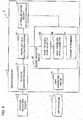
- the course prediction device 1a includes a position detection sensor 9 which detects the position of the surrounding vehicle and a microcomputer 8 which executes a series of information computation processes to predict the course of the host vehicle from the position of the surrounding vehicle detected by the position detection sensor 9.
- the position detection sensor 9 and the microcomputer 8 are both mounted in the host vehicle and are connected to each other by a cable for receiving and sending the position of the surrounding vehicle.
- the position detection sensor 9 includes a radar, a laser radar, a laser range finder (LRF), and a camera but the position detection sensor 9 is not limited to these and may use other known methods.
- means for acquiring depth information by using a camera include not only means using a stereo camera but also means using a monocular camera.
- the microcomputer 8 can be implemented by using a general-purpose microcomputer including a CPU (central processing unit), a memory, and input and output units.
- a computer program (course prediction program) for executing the series of information computation processes for predicting the course of the host vehicle from the position of the surrounding vehicle is installed in the microcomputer 8 and the microcomputer 8 executes the computer program.
- the microcomputer 8 thereby functions as information computation circuits (10, 20, 30, 40) which execute the series of information computation processes.
- the course prediction device 1a is implemented by software
- the information computation circuits (10, 20, 30, 40) described below may be configured as dedicated hardware such as an ASIC, instead of the general-purpose microcomputer, as a matter of course.
- the information computation circuits (10, 20, 30, 40) which are otherwise implemented by the microcomputer 8 may be configured by individual pieces of hardware.
- the microcomputer 8 may be used also as an electronic control unit (ECU) used for other control relating to the vehicle.
- ECU electronice control unit
- the microcomputer 8 functions as a position acquisition circuit 10, a traveling path calculation circuit 20, a lateral deviation amount calculation circuit 30, and a course prediction circuit 40.
- the position acquisition circuit 10 acquires the position of the surrounding vehicle.
- the position acquisition circuit 10 may acquire the position of the surrounding vehicle detected by the position detection sensor 9 from the position detection sensor 9.
- the position acquisition circuit 10 may externally acquire information indicating the position of the surrounding vehicle via a radio communication network.
- the traveling path calculation circuit 20 calculates the traveling path of the surrounding vehicle from a history of the position of the surrounding vehicle acquired by the position acquisition circuit 10. Specifically, the traveling path calculation circuit 20 calculates the traveling path of the surrounding vehicle by connecting the positions of the surrounding vehicle detected at multiple consecutive time points. For example, as illustrated in Fig. 4 , the traveling path calculation circuit 20 may repeatedly plot the position (P 1 , P 2 , P 3 , P 4 , P 5 , ...) of the surrounding vehicle relative to the host vehicle which is detected every predetermined time, on a map in consideration of the moving direction and moving distance of the host vehicle within the predetermined time, and perform curve approximation for multiple positions (path points: P 1 to P 5 , ...) plotted on the map. An approximate curve 83 M thus obtained forms the traveling path of the surrounding vehicle.
- the lateral deviation amount calculation circuit 30 calculates the position (hereafter referred to as "lateral position") of the traveling path calculated by the traveling path calculation circuit 20, relative to the host vehicle in a vehicle width direction of the host vehicle.
- lateral position the position of the traveling path calculated by the traveling path calculation circuit 20, relative to the host vehicle in a vehicle width direction of the host vehicle.
- the lateral position can be indicated by an intersection between the traveling path and the y-axis, that is a y-coordinate of a y-intercept.
- the lateral position is described later with reference to Fig. 3 .
- the lateral deviation amount calculation circuit 30 may determine a lane in which the traveling path is located as the lateral position of the traveling path. For example, the lateral deviation amount calculation circuit 30 detects a lane marker provided on a road surface by using a camera or the like mounted in the host vehicle and calculates the position of the lane marker relative to the host vehicle. Then, the lateral deviation amount calculation circuit 30 determines the lane in which the surrounding vehicle is traveling, that is the lane (adjacent lane, lane adjacent to the adjacent lane, or the like) in which the traveling path is located, based on the position of the lane marker and the position of the traveling path.
- the lateral deviation amount calculation circuit 30 may set the lateral position of the traveling path determined to be in the adjacent lane to, for example, 3 m and set the lateral position of the traveling path determined to be in the lane adjacent to the adjacent lane to, for example, 6 m, instead of an actually measured value.
- the course prediction circuit 40 predicts the course of the host vehicle by increasing or reducing the size of the traveling path of the surrounding vehicle based on the turning direction of the surrounding vehicle and the lateral position calculated by the lateral deviation amount calculation circuit 30. Note that the course prediction circuit 40 determines the turning direction of the surrounding vehicle from the traveling path of the surrounding vehicle calculated by the traveling path calculation circuit 20. For example, when the traveling path has a right curve shape, the course prediction circuit 40 may determine that the turning direction is right and, when the traveling path has a left curve shape, determine that the turning direction is left.
- the course prediction circuit 40 includes a base traveling path selector 40a, a base traveling path corrector 40b, and a course determiner 40c.
- the base traveling path selector 40a selects a traveling path (hereafter, referred to as "base traveling path") to be used as a base in estimation of the course, from traveling paths of multiple surrounding vehicles.
- base traveling path a traveling path
- the position acquisition circuit 10 acquires the positions of the multiple surrounding vehicles, multiple traveling paths and multiple lateral positions are calculated.
- the base traveling path selector 40a selects a traveling path suitable for the estimation of course, based on the lateral positions of the traveling paths. The selection of the base traveling path is described later with reference to Fig. 3 .
- the base traveling path corrector 40b corrects the base traveling path selected by the base traveling path selector 40a, based on the turning direction of the surrounding vehicle and the lateral position of the base traveling path. The correction of the base traveling path is described later with reference to Fig. 4 .
- the course determiner 40c sets the base traveling path corrected by the base traveling path corrector 40b as the course of the host vehicle.
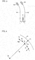
- the lateral positions (Di, Dj) of the traveling paths (83i, 83j) and a method of selecting the base traveling path are specifically described with reference to Fig. 3 .
- the position acquisition circuit 10 acquires the positions of multiple surrounding vehicles (82i, 82j) and the traveling path calculation circuit 20 calculates the traveling paths (83i, 83j) of the respective surrounding vehicles (82i, 82j).
- the lateral deviation amount calculation circuit 30 calculates the lateral positions (Di, Dj) of the respective traveling paths (83i, 83j) relative to a host vehicle 81. Note that, since the traveling paths (83i, 83j) have left curve shapes as illustrated in Fig. 3 , the course prediction circuit 40 determines that the turning directions of the surrounding vehicles are left.
- the base traveling path selector 40a selects the base traveling path from the multiple traveling paths (83i, 83j), based on the lateral positions (Di, Dj) of the traveling paths. Specifically, the base traveling path selector 40a selects the traveling path (83i, 83j) of the surrounding vehicle away from the host vehicle 81 by a distance smaller than a predetermined reference distance, as the base traveling path. For example, when there are multiple surrounding vehicles, the base traveling path selector 40a selects traveling paths (83i, 83j) whose absolute values of the lateral positions (Di, Dj) are smaller than a first reference distance (3 m), from multiple traveling paths, so as to select the base traveling path from the traveling paths of the surrounding vehicles in the host vehicle lane and the adjacent lane.
- the base traveling path selector 40a selects a traveling path of the surrounding vehicle (82i, 82j) whose distance from the host vehicle 81 is smaller than a second reference distance, from the multiple traveling paths (83i, 83j).
- the "distance of the surrounding vehicle (82i, 82j) from the host vehicle 81" is a concept including not only the distance in the vehicle width direction but also the distance in a traveling direction.
- the base traveling path selector 40a selects the traveling path 83j of the surrounding vehicle 82j closest to the host vehicle 81 as the base traveling path, from the traveling paths (83i, 83j) whose the absolute values of the lateral positions (Di, Dj) are smaller than the first reference distance (3 m).
- the base traveling path selector 40a may select the traveling path 83j whose absolute value of the lateral position (Di, Dj) is the smallest, as the base traveling path. In this case, the base traveling path selector 40a does not consider the "distance of the surrounding vehicle (82i, 82j) from the host vehicle 81.” As another alternative, the base traveling path selector 40a may select the traveling path of "the surrounding vehicle (82i, 82j) whose distance from the host vehicle 81" is the smallest, as the base traveling path. In this case, the base traveling path selector 40a does not consider the "absolute values of the lateral positions (Di, Dj)."
- the base traveling path selector 40a selects the traveling path located in the adjacent lane and does not select the traveling path located in the lane adjacent to the adjacent lane.
- the base traveling path corrector 40b increases or reduces the size of the base traveling path 83 M selected by the base traveling path selector 40a, based on the turning direction of the surrounding vehicle and the lateral position D M of the base traveling path 83 M .
- the base traveling path corrector 40b calculates a turning radius R and a turning center 84 at each of path points (P 1 to P 5 , ). For example, the base traveling path corrector 40b calculates the turning radius R and the coordinates of the turning center 84 by using the path point P 3 being the calculation target and the points preceding and following the path point P 3 by means of a least squares method or the like. The base traveling path corrector 40b calculates the turning radius R and the turning center 84 for each of the path points (P 1 to P 5 , ...) in a similar way.
- the base traveling path corrector 40b increases the turning radius R about the turning center 84 at each path points (P 1 to P 5 , ...) to a turning radius (R+D M ) or reduces the turning radius R to a turning radius (R-D M ).
- the base traveling path corrector 40b determines whether to increase or reduce the turning radius R, based on the turning direction and the lateral position D M of the base traveling path 83 M .
- the traveling path 83i of Fig. 3 when the turning direction is left and the lateral position Di of the traveling path 83i is on the left side of the host vehicle 81, the host vehicle 81 is located outside the traveling path 83i of the surrounding vehicle 82i in the turning direction.
- the turning radius at each path point (P 1 to P 5 , ...) of the traveling path 83i is increased to a turning radius (R+Di).
- the traveling path 83j of Fig. 3 when turning direction is left and the lateral position Dj of the traveling path 83j is on the right side of the host vehicle 81, the host vehicle 81 is located inside the traveling path 83j of the surrounding vehicle 82j in the turning direction.
- the turning radius at each path point (P 1 to P 5 , ...) of the traveling path 83j is reduced to a turning radius (R-Dj).
- the base traveling path corrector 40b changes the distance (turning radius) from the turning center 84 to each path point (P 1 to P 5 , ...) without changing the turning center 84.
- the base traveling path corrector 40b increases the turning radius and, when the host vehicle 81 is located inside the traveling path, reduces the turning radius. Then, the base traveling path corrector 40b performs the curve approximation again on the path points (P 3 ') subjected to the turning radius increase or reduction and can thereby correct the base traveling path 83 M .
- the course determiner 40c determines a base traveling path 91 corrected by the base traveling path corrector 40b as the course of the host vehicle as it is.
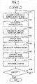
- FIG. 2 An example of a course prediction method using the course prediction device 1a illustrated in Fig. 1 is described with reference to the flowchart of Fig. 2 .
- operation steps of the microcomputer 8 in the course prediction device 1a illustrated in Fig. 1 are described.
- the processing illustrated in Fig. 2 is repeatedly executed at a predetermined cycle.
- step S110 the position acquisition circuit 10 acquires the position of each surrounding vehicle.
- the traveling path calculation circuit 20 calculates the traveling path (approximate curve 83 M ) of each surrounding vehicle from the history (traveling points: P 1 to P 5 , ...) of the position of the surrounding vehicle acquired by the position acquisition circuit 10.
- the lateral deviation amount calculation circuit 30 calculates the lateral position (Di, Dj) of each traveling path (83i, 83j) calculated by the traveling path calculation circuit 20 relative to the host vehicle 81.
- the base traveling path selector 40a selects the base traveling path from the multiple traveling paths (83i, 83j), based on the lateral positions (Di, Dj) of the traveling paths. For example, the base traveling path selector 40a selects the traveling paths (83i, 83j) whose absolute values of the lateral positions (Di, Dj) are smaller than the first reference distance (3 m) and selects the traveling path 83j of the surrounding vehicle 82j closest to the host vehicle 81, as the base traveling path 83 M .
- the method of selecting the base traveling path is not limited to this and the other methods described above may be used.
- the selection of the base traveling path may be performed only when the positions of multiple surrounding vehicles are acquired in step S110.
- the base traveling path selector 40a may select the traveling path of this surrounding vehicle as the base traveling path.
- the processing may be aborted and restarted from step S110 or the traveling path whose absolute value of the lateral position is the smallest may be selected as the base traveling path.
- the base traveling path corrector 40b calculates the turning radius R and the turning center 84 at each path point (P 1 to P 5 , ).
- the base traveling path corrector 40b increases the turning radius R about the turning center 84 at each path point (P 1 to P 5 , ...) to the turning radius (R+D M ) or reduces the turning radius R to the turning radius (R-D M ).
- the base traveling path corrector 40b determines whether to increase or reduce the turning radius R, based on the turning direction and the lateral position of the base traveling path 83 M . Then, the base traveling path corrector 40b performs the curve approximation again on the path points (P 3 ') subjected to the turning radius increase or reduction and thereby corrects the base traveling path 83 M .
- the course determiner 40c determines the base traveling path 91 corrected by the base traveling path corrector 40b as the course of the host vehicle as it is.
- step S0180 the microcomputer 8 determines whether an ignition switch of the host vehicle 81 is turned off and repeatedly executes steps S110 to S170 described above at a predetermined cycle until the ignition switch is turned off.
- the ignition switch is turned off (YES in step S180)
- the aforementioned processing cycle is terminated.
- the microcomputer 8 predicts the course of the host vehicle 81 by increasing or reducing the size of the traveling path (83i, 83j) of the surrounding vehicle (82i, 82j).
- the microcomputer 8 can thereby predict the course of the host vehicle 81 by using the traveling path (83i, 83j) of the surrounding vehicle (82i, 82j) traveling in the lane other than the host vehicle lane. For example, as illustrated in part (a) of Fig. 5 , assume a situation where the host vehicle 81 cannot detect the position of a preceding vehicle 89 due to the surrounding vehicle 82 or the like.
- a curve shape of a traveling path (adjacent lane) of the surrounding vehicle 82 is different from a curve shape of a traveling path (host vehicle lane) of the preceding vehicle 89. Accordingly, when a conventional method of predicting the course of the host vehicle 81 from the traveling path of the preceding vehicle 89 is applied, as illustrated in part (b) of Fig. 5 , a curve shape 90 of the host vehicle lane cannot be appropriately predicted. In the first embodiment, also in the situation illustrated in part (a) of Fig. 5 , the microcomputer 8 can accurately predict the curve shape of the host vehicle 81 by using the traveling path 83 of the surrounding vehicle 82 traveling in the adjacent lane or the like.
- the base traveling path corrector 40b can thereby appropriately predict the course depending on the curve shape.
- the base traveling path corrector 40b can thereby appropriately predict the course also when the lane in which the host vehicle 81 is traveling is different from the lane in which the surrounding vehicle 82 is traveling (the adjacent lane or the lane adjacent to the adjacent lane).
- the microcomputer 8 predicts the course based on the traveling path (83i, 83j) of the surrounding vehicle whose distance from the host vehicle 81 is the smallest. The closer the position of the surrounding vehicle (82i, 82j) to the host vehicle 81 is, the higher the detection accuracy of this position is. Accordingly, the microcomputer 8 predicts the course based on the traveling path (83i, 83j) of the surrounding vehicle (82i, 82j) whose distance from the host vehicle 81 is the smallest, and can thereby appropriately predict the course from the highly-accurate traveling path (83i, 83j).
- the microcomputer 8 predicts the course based on the traveling path 83j of the surrounding vehicle in the lane adjacent to the lane in which the host vehicle 81 is traveling.
- the microcomputer 8 can thereby appropriately predict the course from the highly-accurate traveling path 83j.
- the course prediction device 1b acquires map information including at least branching information of roads and does not predict the course of the host vehicle when determining that the host vehicle 81 is to pass a branching point.
- the course prediction device 1b determines that the host vehicle 81 is to pass no branching point
- the course determiner 40c determines the base traveling path 91 corrected by the base traveling path corrector 40b as the course of the host vehicle.
- the course prediction device 1b further includes a map database 7.
- the map database 7 and the microcomputer 8 are both mounted in the host vehicle 81 and are connected each other by a cable for receiving and sending the map information including at least the branching information of roads.
- the microcomputer 8 functions not only as the information computation circuits (10, 20, 30, 40) but also as a map acquisition circuit 50.
- the map acquisition circuit 50 acquires the map information including at least the branching information of roads, from the map database 7.
- the other configurations of the course prediction device 1b are the same as those of the course prediction device 1a in Fig. 1 and description thereof is omitted.
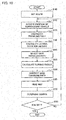
- FIG. 7 An example of a course prediction method using the course prediction device 1b illustrated in Fig. 6 is described with reference to the flowchart of Fig. 7 .
- operation steps of the microcomputer 8 in the course prediction device 1b illustrated in Fig. 6 are described.
- the processing illustrated in Fig. 7 is repeatedly executed at a predetermined cycle.
- the flowchart of Fig. 7 further includes step S165 and is different in the contents of step S170.
- the contents of processing in steps S110 to S160 and S180 in Fig. 7 are the same as those in Fig. 2 and description thereof is omitted.
- step S160 the processing proceeds to step S165 and the map acquisition circuit 50 acquires the map information including at least the branching information of roads, from the map database 7. Specifically, the map acquisition circuit 50 reads the map information including the branching information of a road on which the host vehicle 81 is traveling, from the map database 7.
- the course determiner 40c predicts the course of the host vehicle from the corrected base traveling path 91, the map information, and the absolute value of the lateral position D M .
- the course determiner 40c determines whether the host vehicle 81 is to pass a branching point within a predetermined time. Specifically, as illustrated in Fig. 8 , the course determiner 40c determines whether a road on which the host vehicle 81 is traveling includes a point (branching point 87) where the road branches into two or more roads (85, 86) in front of the host vehicle 81 within a predetermined distance therefrom.
- the course determiner 40c determines that the absolute value of the lateral position D M of the base traveling path 83 M is a third reference distance (1.5 m) or more and that the host vehicle 81 is to pass the branching point 87 within the predetermined time, the course determiner 40c does not predict the course of the host vehicle 81.
- the course determiner 40c determines that the surrounding vehicle for which the traveling path can be calculated is traveling in a lane other than the host vehicle lane (the distance to the lateral position D M is the third reference distance (1.5 m) or more) and that the host vehicle 81 is to pass the branching point 87, the course determiner 40c does not set the base traveling path 91 corrected by the base traveling path corrector 40b as the course of the host vehicle 81.
- the course determiner 40c determines that the absolute value of the lateral position D M of the base traveling path 83 M is less than the third reference distance (1.5 m) or that the host vehicle 81 is to pass no branching point 87 within the predetermined time, the course determiner 40c sets the base traveling path 91 corrected by the base traveling path corrector 40b as the course of the host vehicle 81.
- the course determiner 40c determines that the surrounding vehicle for which the traveling path can be calculated is traveling in the host vehicle lane (the distance to the lateral position D M is less than the third reference distance (1.5 m)) or that the host vehicle 81 is to pass no branching point, the course determiner 40c sets the base traveling path 91 corrected by the base traveling path corrector 40b as the course of the host vehicle 81.
- the course is not predicted when the host vehicle 81 is to pass the branching point 87. Accordingly, as illustrated in Fig. 8 , erroneous course prediction can be prevented when the surrounding vehicle 82 leaves in a direction (road 86) different from the course (road 85) of the host vehicle 81 at the branching point 87. Specifically, when the traveling path 83 of the surrounding vehicle and the course of the host vehicle are to be located in different roads (85, 86) from the branching point 87, the course determiner 40c prevents the corrected base traveling path 91 from being set as the course of the host vehicle 81. Erroneous course prediction can be thereby avoided.
- the course determiner 40c may determine the course based only on the presence or absence of the branching point 87. For example, no matter where the position of the lane of the surrounding vehicle for which the traveling path can be calculated is, the course determiner 40c may not predict the course of the host vehicle lane irrespective of the lateral position D M of the base traveling path 83 M when determining that the host vehicle 81 is to pass the branching point 87 within the predetermined time.
- the course prediction device 1c acquires at least travel route information of the host vehicle 81 on a map and predicts the course based on the traveling path 83 of the surrounding vehicle 82 similar to a travel route of the host vehicle 81.
- the course determiner 40c determines the base traveling path 91 corrected by the base traveling path corrector 40b as the course of the host vehicle only when the corrected base traveling path 91 is determined to be similar to the travel route of the host vehicle 81.
- the course prediction device 1c further includes a navigation device 6.
- the navigation device 6, the map database 7, and the microcomputer 8 are all mounted in the host vehicle 81.
- the navigation device 6 and the microcomputer 8 are connected to each other by a cable for receiving and sending the traveling route information of the host vehicle 81.
- the microcomputer 8 functions not only as the information computation circuits (10, 20, 30, 40, 50) but also as a route acquisition circuit 60.
- the route acquisition circuit 60 acquires the travel route information of the host vehicle 81 from the navigation device 6.
- the map acquisition circuit 50 acquires map information including the branching information of roads, intersection information, and shape information (including turning radius information) of roads.
- the other configurations of the course prediction device 1c are the same as those of the course prediction device 1b in Fig. 6 and description thereof is omitted.
- FIG. 10 An example of a course prediction method using the course prediction device 1c illustrated in Fig. 9 is described with reference to the flowchart of Fig. 10 .
- operation steps of the microcomputer 8 in the course prediction device 1c illustrated in Fig. 9 are described.
- the processing illustrated in Fig. 10 is repeatedly executed at a predetermined cycle.
- the flowchart of Fig. 10 further includes step S100 and is different in the contents of step S170.
- the contents of processing in steps S110 to S160 and S180 in Fig. 10 are the same as those in Fig. 7 and description thereof is omitted.
- step S100 the route acquisition circuit 60 acquires the travel route information of the host vehicle 81 from the navigation device 6. Then, the processing proceeds to step S110.
- step S170 when the course determiner 40c determines that the absolute value of the lateral position D M of the base traveling path 83 M is the first reference distance or more and that the host vehicle 81 is to pass the branching point 87, the course determiner 40c does not set the corrected base traveling path 91 as the course of the host vehicle 81. This is the same as the second embodiment.
- step S170 the course determiner 40c further determines whether the branching point 87 is an intersection 88. Then, when the branching point 87 is the intersection 88, the course determiner 40c determines whether the base traveling path 91 corrected in the step S160 is similar to the travel route of the host vehicle 81 acquired in step S100.
- the course determiner 40c determines that the branching point 87 is the intersection 88 and that the corrected base traveling path 91 is similar to the travel route of the host vehicle 81, the course determiner 40c sets the base traveling path 91 corrected in step S160 as the course of the host vehicle lane.
- the course determiner 40c may not set the corrected base traveling path 91 as the course of the host vehicle lane when the following condition is established. Specifically, the course determiner 40c may not set the corrected base traveling path 91 as the course of the host vehicle lane when a state where the absolute value of the lateral position D M of the base traveling path 83 M is the third reference distance (1.5 m) or more continues for a predetermined time (for example, 5 seconds) or more.
- the course can be appropriately predicted by using the traveling path of the surrounding vehicle which runs parallel to the traveling route of the host vehicle 81.
- the third embodiment is described as an example based on the second embodiment, the third embodiment may be carried out based on the first embodiment.
- the course determiner 40c determines whether the base traveling path 91 corrected in step S160 is similar to the traveling route of the host vehicle 81 acquired in step S100. When the base traveling path 91 is not similar, the course determiner 40c does not set the base traveling path 91 corrected by the base traveling path corrector 40b as the course of the host vehicle. Meanwhile, when the base traveling path 91 is similar, the course determiner 40c sets the base traveling path 91 corrected by the base traveling path corrector 40b as the course of the host vehicle.
- step S170 the course determiner 40c does not determine whether the absolute value of the lateral position D M is the first reference distance or more, whether the host vehicle 81 passes the branching point 87, or whether the branching point 87 is the intersection 88. Step S165 (reading of the map) is also unnecessary.
- the course prediction device may include no position detection sensor 9.
- the course prediction device (1a to 1c) includes a radio communication unit and the position acquisition circuit 10 can externally acquire information indicating the position of the surrounding vehicle via a radio communication network.
- the course prediction device (1a to 1c) may include neither map database 7 nor navigation device 6.
- the map acquisition circuit 50 and the route acquisition circuit 60 may externally acquire the map information and the travel route information via a computer network.
- the course prediction device (1a to 1c) may not be mounted in the host vehicle 81.
- the course prediction device (1a to 1c) may be a backend (cloud itself) in a cloud computing model.
- the host vehicle 81 being a frontend is connected to the course prediction device (1a to 1c) being the backend via a network such as the Internet.
- the course prediction device (1a to 1c) may predict the course of the host vehicle 81 by acquiring the information indicating the position of the surrounding vehicle 82 from the surrounding vehicle 82 itself or from the host vehicle 81 (the detection result of the position detection sensor 9) to predict the course of the host vehicle 81 and provide the predicted course to the host vehicle 81 via the network.
- the functions described in the aforementioned embodiments can be implemented by one or multiple processing circuits.
- the processing circuit includes a programed processing device such as a processing device including an electric circuit.
- the processing device includes devices such as an application-specific integrated circuit (ASIC) and conventional circuit parts which are designed to execute the functions described in the embodiments.
- ASIC application-specific integrated circuit
Landscapes
- Engineering & Computer Science (AREA)
- Automation & Control Theory (AREA)
- Transportation (AREA)
- Mechanical Engineering (AREA)
- Physics & Mathematics (AREA)
- Mathematical Physics (AREA)
- General Physics & Mathematics (AREA)
- Radar, Positioning & Navigation (AREA)
- Remote Sensing (AREA)
- Aviation & Aerospace Engineering (AREA)
- Traffic Control Systems (AREA)
- Control Of Driving Devices And Active Controlling Of Vehicle (AREA)
Abstract
Description
- The present invention relates to a course prediction method and a course prediction device.
- There has been conventionally known a steering control technique in which a traveling path of a preceding vehicle is acquired or calculated and a curve shape of a lane on which a host vehicle is traveling (host vehicle lane) is predicted from the traveling path of the preceding vehicle (see Patent Literature 1).
- Patent Literature 1: Japanese Patent Application Publication No.
2013-226973 - However, in Patent Literature 1, it is difficult to predict the curve shape of the host vehicle lane from a traveling path of a surrounding vehicle traveling in a lane other than the host vehicle lane.
- The present invention has been made in view of the aforementioned problem and an object thereof is to provide a course prediction method and a course prediction device which can predict a course of a host vehicle from a traveling path of a surrounding vehicle.
- In one aspect of the present invention, a course of a host vehicle is predicted by increasing or reducing the size of a traveling path of a surrounding vehicle, based on a turning direction and a lateral position of the surrounding vehicle.
- According to one aspect of the present invention, since the course of the host vehicle is predicted by increasing or reducing the size of the traveling path of the surrounding vehicle, the course of the host vehicle can be predicted by using the traveling path of the surrounding vehicle traveling in a lane other than a host vehicle lane.
-
-
Fig. 1 is a block diagram illustrating an overall configuration of acourse prediction device 1a according to a first embodiment. -
Fig. 2 is a flowchart explaining an example of a course prediction method using thecourse prediction device 1a illustrated inFig. 1 . -
Fig. 3 is a bird's eye view of surrounding vehicles (82i, 82j) and their traveling paths (83i, 83j) from above ahost vehicle 81. -
Fig. 4 is a bird's eye view which illustrates multiple path points (P1, P2, P3, P4, P5, ...) on a map and atraveling path 83M formed of an approximate curve of these points and which explains an example of a specific method of predicting the course of the host vehicle by correcting abase traveling path 83M. - Part (a) of
Fig. 5 is a bird's eye view illustrating a situation where thehost vehicle 81 cannot detect the position of a precedingvehicle 89 due to a surroundingvehicle 82, and part (b) ofFig. 5 is a bird's eye view illustrating a state where acurve shape 90 of the host vehicle lane cannot be appropriately predicted. -
Fig. 6 is a block diagram illustrating an overall configuration of acourse prediction device 1b according to a second embodiment -
Fig. 7 is a flowchart illustrating an example of a course prediction method using thecourse prediction device 1b illustrated inFig. 6 . -
Fig. 8 is a bird's eye view illustrating a case where thehost vehicle 81 is determined to pass abranching point 87 within a predetermined time. -
Fig. 9 is a block diagram illustrating an overall configuration of acourse prediction device 1c according to a third embodiment. -
Fig. 10 is a flowchart illustrating an example of a course prediction method using thecourse prediction device 1c illustrated inFig. 9 . -
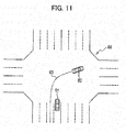
Fig. 11 is a bird's eye view illustrating a case where thehost vehicle 81 is determined to pass anintersection 88 within a predetermined time. - Next, an embodiment is described in detail with reference to the drawings.
- An overall configuration of a
course prediction device 1a according to a first embodiment is described with reference toFig. 1 . Thecourse prediction device 1a predicts a course of a host vehicle from a position of a surrounding vehicle. The "surrounding vehicle" refers to another vehicle which travels around the host vehicle in a lane (adjacent lane) adjacent to a lane (host vehicle lane) in which the host vehicle is traveling, a lane adjacent to the adjacent lane, or the like. - The
course prediction device 1a includes aposition detection sensor 9 which detects the position of the surrounding vehicle and amicrocomputer 8 which executes a series of information computation processes to predict the course of the host vehicle from the position of the surrounding vehicle detected by theposition detection sensor 9. Theposition detection sensor 9 and themicrocomputer 8 are both mounted in the host vehicle and are connected to each other by a cable for receiving and sending the position of the surrounding vehicle. - Specific examples of the
position detection sensor 9 include a radar, a laser radar, a laser range finder (LRF), and a camera but theposition detection sensor 9 is not limited to these and may use other known methods. Note that means for acquiring depth information by using a camera include not only means using a stereo camera but also means using a monocular camera. - The
microcomputer 8 can be implemented by using a general-purpose microcomputer including a CPU (central processing unit), a memory, and input and output units. A computer program (course prediction program) for executing the series of information computation processes for predicting the course of the host vehicle from the position of the surrounding vehicle is installed in themicrocomputer 8 and themicrocomputer 8 executes the computer program. Themicrocomputer 8 thereby functions as information computation circuits (10, 20, 30, 40) which execute the series of information computation processes. Note that, although an example in which thecourse prediction device 1a is implemented by software is explained in this description, the information computation circuits (10, 20, 30, 40) described below may be configured as dedicated hardware such as an ASIC, instead of the general-purpose microcomputer, as a matter of course. Alternatively, the information computation circuits (10, 20, 30, 40) which are otherwise implemented by themicrocomputer 8 may be configured by individual pieces of hardware. Furthermore, themicrocomputer 8 may be used also as an electronic control unit (ECU) used for other control relating to the vehicle. - The
microcomputer 8 functions as aposition acquisition circuit 10, a travelingpath calculation circuit 20, a lateral deviationamount calculation circuit 30, and acourse prediction circuit 40. - The
position acquisition circuit 10 acquires the position of the surrounding vehicle. Theposition acquisition circuit 10 may acquire the position of the surrounding vehicle detected by theposition detection sensor 9 from theposition detection sensor 9. As a matter of course, theposition acquisition circuit 10 may externally acquire information indicating the position of the surrounding vehicle via a radio communication network. - The traveling
path calculation circuit 20 calculates the traveling path of the surrounding vehicle from a history of the position of the surrounding vehicle acquired by theposition acquisition circuit 10. Specifically, the travelingpath calculation circuit 20 calculates the traveling path of the surrounding vehicle by connecting the positions of the surrounding vehicle detected at multiple consecutive time points. For example, as illustrated inFig. 4 , the travelingpath calculation circuit 20 may repeatedly plot the position (P1, P2, P3, P4, P5, ...) of the surrounding vehicle relative to the host vehicle which is detected every predetermined time, on a map in consideration of the moving direction and moving distance of the host vehicle within the predetermined time, and perform curve approximation for multiple positions (path points: P1 to P5, ...) plotted on the map. Anapproximate curve 83M thus obtained forms the traveling path of the surrounding vehicle. - The lateral deviation
amount calculation circuit 30 calculates the position (hereafter referred to as "lateral position") of the traveling path calculated by the travelingpath calculation circuit 20, relative to the host vehicle in a vehicle width direction of the host vehicle. For example, in a two-dimensional coordinate system in which the origin is the host vehicle and a vehicle front-rear direction and the vehicle width direction are an x-axis and a y-axis, respectively, the lateral position can be indicated by an intersection between the traveling path and the y-axis, that is a y-coordinate of a y-intercept. The lateral position is described later with reference toFig. 3 . - Alternatively, the lateral deviation
amount calculation circuit 30 may determine a lane in which the traveling path is located as the lateral position of the traveling path. For example, the lateral deviationamount calculation circuit 30 detects a lane marker provided on a road surface by using a camera or the like mounted in the host vehicle and calculates the position of the lane marker relative to the host vehicle. Then, the lateral deviationamount calculation circuit 30 determines the lane in which the surrounding vehicle is traveling, that is the lane (adjacent lane, lane adjacent to the adjacent lane, or the like) in which the traveling path is located, based on the position of the lane marker and the position of the traveling path. Since the width of the lane varies depending on a road section, the lateral deviationamount calculation circuit 30 may set the lateral position of the traveling path determined to be in the adjacent lane to, for example, 3 m and set the lateral position of the traveling path determined to be in the lane adjacent to the adjacent lane to, for example, 6 m, instead of an actually measured value. - The
course prediction circuit 40 predicts the course of the host vehicle by increasing or reducing the size of the traveling path of the surrounding vehicle based on the turning direction of the surrounding vehicle and the lateral position calculated by the lateral deviationamount calculation circuit 30. Note that thecourse prediction circuit 40 determines the turning direction of the surrounding vehicle from the traveling path of the surrounding vehicle calculated by the travelingpath calculation circuit 20. For example, when the traveling path has a right curve shape, thecourse prediction circuit 40 may determine that the turning direction is right and, when the traveling path has a left curve shape, determine that the turning direction is left. - The
course prediction circuit 40 includes a basetraveling path selector 40a, a basetraveling path corrector 40b, and a course determiner 40c. - The base
traveling path selector 40a selects a traveling path (hereafter, referred to as "base traveling path") to be used as a base in estimation of the course, from traveling paths of multiple surrounding vehicles. When theposition acquisition circuit 10 acquires the positions of the multiple surrounding vehicles, multiple traveling paths and multiple lateral positions are calculated. In this case, the basetraveling path selector 40a selects a traveling path suitable for the estimation of course, based on the lateral positions of the traveling paths. The selection of the base traveling path is described later with reference toFig. 3 . - The base
traveling path corrector 40b corrects the base traveling path selected by the basetraveling path selector 40a, based on the turning direction of the surrounding vehicle and the lateral position of the base traveling path. The correction of the base traveling path is described later with reference toFig. 4 . - The
course determiner 40c sets the base traveling path corrected by the base travelingpath corrector 40b as the course of the host vehicle. - The lateral positions (Di, Dj) of the traveling paths (83i, 83j) and a method of selecting the base traveling path are specifically described with reference to
Fig. 3 . In the example illustrated inFig. 3 , theposition acquisition circuit 10 acquires the positions of multiple surrounding vehicles (82i, 82j) and the travelingpath calculation circuit 20 calculates the traveling paths (83i, 83j) of the respective surrounding vehicles (82i, 82j). Then, the lateral deviationamount calculation circuit 30 calculates the lateral positions (Di, Dj) of the respective traveling paths (83i, 83j) relative to ahost vehicle 81. Note that, since the traveling paths (83i, 83j) have left curve shapes as illustrated inFig. 3 , thecourse prediction circuit 40 determines that the turning directions of the surrounding vehicles are left. - The base traveling
path selector 40a selects the base traveling path from the multiple traveling paths (83i, 83j), based on the lateral positions (Di, Dj) of the traveling paths. Specifically, the base travelingpath selector 40a selects the traveling path (83i, 83j) of the surrounding vehicle away from thehost vehicle 81 by a distance smaller than a predetermined reference distance, as the base traveling path. For example, when there are multiple surrounding vehicles, the base travelingpath selector 40a selects traveling paths (83i, 83j) whose absolute values of the lateral positions (Di, Dj) are smaller than a first reference distance (3 m), from multiple traveling paths, so as to select the base traveling path from the traveling paths of the surrounding vehicles in the host vehicle lane and the adjacent lane. When the absolute values of the lateral positions (Di, Dj) of multiple traveling paths (83i, 83j) are smaller than the first reference distance (3 m), the base travelingpath selector 40a selects a traveling path of the surrounding vehicle (82i, 82j) whose distance from thehost vehicle 81 is smaller than a second reference distance, from the multiple traveling paths (83i, 83j). Here, the "distance of the surrounding vehicle (82i, 82j) from thehost vehicle 81" is a concept including not only the distance in the vehicle width direction but also the distance in a traveling direction. For example, the base travelingpath selector 40a selects the travelingpath 83j of the surroundingvehicle 82j closest to thehost vehicle 81 as the base traveling path, from the traveling paths (83i, 83j) whose the absolute values of the lateral positions (Di, Dj) are smaller than the first reference distance (3 m). - Alternatively, the base traveling
path selector 40a may select the travelingpath 83j whose absolute value of the lateral position (Di, Dj) is the smallest, as the base traveling path. In this case, the base travelingpath selector 40a does not consider the "distance of the surrounding vehicle (82i, 82j) from thehost vehicle 81." As another alternative, the base travelingpath selector 40a may select the traveling path of "the surrounding vehicle (82i, 82j) whose distance from thehost vehicle 81" is the smallest, as the base traveling path. In this case, the base travelingpath selector 40a does not consider the "absolute values of the lateral positions (Di, Dj)." - Note that, when the lane (adjacent lane, lane adjacent to the adjacent lane, or the like) in which each traveling path is located is used as the lateral position of the traveling path, for example, the base traveling
path selector 40a selects the traveling path located in the adjacent lane and does not select the traveling path located in the lane adjacent to the adjacent lane. - An example of a specific method of predicting the course of the
host vehicle 81 by correcting abase traveling path 83M is described with reference toFig. 4 . The base travelingpath corrector 40b increases or reduces the size of thebase traveling path 83M selected by the base travelingpath selector 40a, based on the turning direction of the surrounding vehicle and the lateral position DM of thebase traveling path 83M. - First, the base traveling
path corrector 40b calculates a turning radius R and aturning center 84 at each of path points (P1 to P5, ...). For example, the base travelingpath corrector 40b calculates the turning radius R and the coordinates of theturning center 84 by using the path point P3 being the calculation target and the points preceding and following the path point P3 by means of a least squares method or the like. The base travelingpath corrector 40b calculates the turning radius R and theturning center 84 for each of the path points (P1 to P5, ...) in a similar way. - Next, the base traveling
path corrector 40b increases the turning radius R about theturning center 84 at each path points (P1 to P5, ...) to a turning radius (R+DM) or reduces the turning radius R to a turning radius (R-DM). The base travelingpath corrector 40b determines whether to increase or reduce the turning radius R, based on the turning direction and the lateral position DM of thebase traveling path 83M. - For example, as in the traveling path 83i of
Fig. 3 , when the turning direction is left and the lateral position Di of the traveling path 83i is on the left side of thehost vehicle 81, thehost vehicle 81 is located outside the traveling path 83i of the surrounding vehicle 82i in the turning direction. In this case, as inFig. 4 , the turning radius at each path point (P1 to P5, ...) of the traveling path 83i is increased to a turning radius (R+Di). - Meanwhile, as in the traveling
path 83j ofFig. 3 , when turning direction is left and the lateral position Dj of the travelingpath 83j is on the right side of thehost vehicle 81, thehost vehicle 81 is located inside the travelingpath 83j of the surroundingvehicle 82j in the turning direction. In this case, contrary toFig. 4 , the turning radius at each path point (P1 to P5, ...) of the travelingpath 83j is reduced to a turning radius (R-Dj). - As described above, the base traveling
path corrector 40b changes the distance (turning radius) from the turningcenter 84 to each path point (P1 to P5, ...) without changing theturning center 84. When thehost vehicle 81 is located outside the traveling path in the turning direction, the base travelingpath corrector 40b increases the turning radius and, when thehost vehicle 81 is located inside the traveling path, reduces the turning radius. Then, the base travelingpath corrector 40b performs the curve approximation again on the path points (P3') subjected to the turning radius increase or reduction and can thereby correct thebase traveling path 83M. - The larger the turning radius R of the
base traveling path 83M is, the smaller the degree of increasing or reducing by the base travelingpath corrector 40b is made. In other words, provided that the lateral position D is constant, the larger the turning radius R is, the smaller the increase ratio (= (R+DM)/R) and the reduction ratio (= (R-DM)/R) are. - The greater the distance from the
host vehicle 81 to the lateral position DM of the surroundingvehicle 82 is, the greater the degree of increasing or reducing by the base travelingpath corrector 40b is made. In other words, provided that the turning radius R is constant, the larger the absolute value of the lateral position DM is, the larger the increase ratio and the reduction ratio are. - In the first embodiment, the
course determiner 40c determines abase traveling path 91 corrected by the base travelingpath corrector 40b as the course of the host vehicle as it is. - An example of a course prediction method using the
course prediction device 1a illustrated inFig. 1 is described with reference to the flowchart ofFig. 2 . Here, operation steps of themicrocomputer 8 in thecourse prediction device 1a illustrated inFig. 1 are described. The processing illustrated inFig. 2 is repeatedly executed at a predetermined cycle. - First, in step S110, the
position acquisition circuit 10 acquires the position of each surrounding vehicle. - Proceeding to step S0120, as illustrated in
Fig. 4 , the travelingpath calculation circuit 20 calculates the traveling path (approximate curve 83M) of each surrounding vehicle from the history (traveling points: P1 to P5, ...) of the position of the surrounding vehicle acquired by theposition acquisition circuit 10. - Proceeding to step S0130, as illustrated in
Fig. 3 , the lateral deviationamount calculation circuit 30 calculates the lateral position (Di, Dj) of each traveling path (83i, 83j) calculated by the travelingpath calculation circuit 20 relative to thehost vehicle 81. - Proceeding to step S0140, as illustrated in
Fig. 3 , the base travelingpath selector 40a selects the base traveling path from the multiple traveling paths (83i, 83j), based on the lateral positions (Di, Dj) of the traveling paths. For example, the base travelingpath selector 40a selects the traveling paths (83i, 83j) whose absolute values of the lateral positions (Di, Dj) are smaller than the first reference distance (3 m) and selects the travelingpath 83j of the surroundingvehicle 82j closest to thehost vehicle 81, as thebase traveling path 83M. However, the method of selecting the base traveling path is not limited to this and the other methods described above may be used. Note that the selection of the base traveling path may be performed only when the positions of multiple surrounding vehicles are acquired in step S110. When the position of only one surrounding vehicle is acquired, the base travelingpath selector 40a may select the traveling path of this surrounding vehicle as the base traveling path. Moreover, when there is no traveling path whose absolute value of the lateral position is smaller than the first reference distance, the processing may be aborted and restarted from step S110 or the traveling path whose absolute value of the lateral position is the smallest may be selected as the base traveling path. - Proceeding to step S0150, as illustrated in
Fig. 4 , the base travelingpath corrector 40b calculates the turning radius R and theturning center 84 at each path point (P1 to P5, ...). - Proceeding to step S0160, as illustrated in
Fig. 4 , the base travelingpath corrector 40b increases the turning radius R about theturning center 84 at each path point (P1 to P5, ...) to the turning radius (R+DM) or reduces the turning radius R to the turning radius (R-DM). The base travelingpath corrector 40b determines whether to increase or reduce the turning radius R, based on the turning direction and the lateral position of thebase traveling path 83M. Then, the base travelingpath corrector 40b performs the curve approximation again on the path points (P3') subjected to the turning radius increase or reduction and thereby corrects thebase traveling path 83M. - Proceeding to step S0170, the
course determiner 40c determines thebase traveling path 91 corrected by the base travelingpath corrector 40b as the course of the host vehicle as it is. - Proceeding to step S0180, the
microcomputer 8 determines whether an ignition switch of thehost vehicle 81 is turned off and repeatedly executes steps S110 to S170 described above at a predetermined cycle until the ignition switch is turned off. When the ignition switch is turned off (YES in step S180), the aforementioned processing cycle is terminated. - As described above, in the first embodiment, the following operations and effects are obtained.
- The
microcomputer 8 predicts the course of thehost vehicle 81 by increasing or reducing the size of the traveling path (83i, 83j) of the surrounding vehicle (82i, 82j). Themicrocomputer 8 can thereby predict the course of thehost vehicle 81 by using the traveling path (83i, 83j) of the surrounding vehicle (82i, 82j) traveling in the lane other than the host vehicle lane. For example, as illustrated in part (a) ofFig. 5 , assume a situation where thehost vehicle 81 cannot detect the position of a precedingvehicle 89 due to the surroundingvehicle 82 or the like. A curve shape of a traveling path (adjacent lane) of the surroundingvehicle 82 is different from a curve shape of a traveling path (host vehicle lane) of the precedingvehicle 89. Accordingly, when a conventional method of predicting the course of thehost vehicle 81 from the traveling path of the precedingvehicle 89 is applied, as illustrated in part (b) ofFig. 5 , acurve shape 90 of the host vehicle lane cannot be appropriately predicted. In the first embodiment, also in the situation illustrated in part (a) ofFig. 5 , themicrocomputer 8 can accurately predict the curve shape of thehost vehicle 81 by using the travelingpath 83 of the surroundingvehicle 82 traveling in the adjacent lane or the like. - As illustrated in
Fig. 4 , the larger the turning radius of the travelingpath 83M is, the smaller the degree of increasing or reducing by the base travelingpath corrector 40b is made. The base travelingpath corrector 40b can thereby appropriately predict the course depending on the curve shape. - As illustrated in
Fig. 4 , the greater the distance from thehost vehicle 81 to the lateral position DM of the surroundingvehicle 82 is, the greater the degree of increasing or reducing by the base travelingpath corrector 40b is made. The base travelingpath corrector 40b can thereby appropriately predict the course also when the lane in which thehost vehicle 81 is traveling is different from the lane in which the surroundingvehicle 82 is traveling (the adjacent lane or the lane adjacent to the adjacent lane). - The
microcomputer 8 predicts the course based on the traveling path (83i, 83j) of the surrounding vehicle whose distance from thehost vehicle 81 is the smallest. The closer the position of the surrounding vehicle (82i, 82j) to thehost vehicle 81 is, the higher the detection accuracy of this position is. Accordingly, themicrocomputer 8 predicts the course based on the traveling path (83i, 83j) of the surrounding vehicle (82i, 82j) whose distance from thehost vehicle 81 is the smallest, and can thereby appropriately predict the course from the highly-accurate traveling path (83i, 83j). - Moreover, the
microcomputer 8 predicts the course based on the travelingpath 83j of the surrounding vehicle in the lane adjacent to the lane in which thehost vehicle 81 is traveling. Themicrocomputer 8 can thereby appropriately predict the course from the highly-accurate traveling path 83j. - An overall configuration of a
course prediction device 1b according to a second embodiment is described with reference toFig. 6 . Thecourse prediction device 1b acquires map information including at least branching information of roads and does not predict the course of the host vehicle when determining that thehost vehicle 81 is to pass a branching point. When thecourse prediction device 1b determines that thehost vehicle 81 is to pass no branching point, thecourse determiner 40c determines thebase traveling path 91 corrected by the base travelingpath corrector 40b as the course of the host vehicle. - As illustrated in
Fig. 6 , thecourse prediction device 1b further includes amap database 7. Themap database 7 and themicrocomputer 8 are both mounted in thehost vehicle 81 and are connected each other by a cable for receiving and sending the map information including at least the branching information of roads. - The
microcomputer 8 functions not only as the information computation circuits (10, 20, 30, 40) but also as amap acquisition circuit 50. Themap acquisition circuit 50 acquires the map information including at least the branching information of roads, from themap database 7. - The other configurations of the
course prediction device 1b are the same as those of thecourse prediction device 1a inFig. 1 and description thereof is omitted. - An example of a course prediction method using the
course prediction device 1b illustrated inFig. 6 is described with reference to the flowchart ofFig. 7 . Here, operation steps of themicrocomputer 8 in thecourse prediction device 1b illustrated inFig. 6 are described. The processing illustrated inFig. 7 is repeatedly executed at a predetermined cycle. - In comparison with
Fig. 2 , the flowchart ofFig. 7 further includes step S165 and is different in the contents of step S170. The contents of processing in steps S110 to S160 and S180 inFig. 7 are the same as those inFig. 2 and description thereof is omitted. - After step S160, the processing proceeds to step S165 and the
map acquisition circuit 50 acquires the map information including at least the branching information of roads, from themap database 7. Specifically, themap acquisition circuit 50 reads the map information including the branching information of a road on which thehost vehicle 81 is traveling, from themap database 7. - Proceeding to step S170, the
course determiner 40c predicts the course of the host vehicle from the correctedbase traveling path 91, the map information, and the absolute value of the lateral position DM. Thecourse determiner 40c determines whether thehost vehicle 81 is to pass a branching point within a predetermined time. Specifically, as illustrated inFig. 8 , thecourse determiner 40c determines whether a road on which thehost vehicle 81 is traveling includes a point (branching point 87) where the road branches into two or more roads (85, 86) in front of thehost vehicle 81 within a predetermined distance therefrom. When thecourse determiner 40c determines that the absolute value of the lateral position DM of thebase traveling path 83M is a third reference distance (1.5 m) or more and that thehost vehicle 81 is to pass the branchingpoint 87 within the predetermined time, thecourse determiner 40c does not predict the course of thehost vehicle 81. Specifically, when thecourse determiner 40c determines that the surrounding vehicle for which the traveling path can be calculated is traveling in a lane other than the host vehicle lane (the distance to the lateral position DM is the third reference distance (1.5 m) or more) and that thehost vehicle 81 is to pass the branchingpoint 87, thecourse determiner 40c does not set thebase traveling path 91 corrected by the base travelingpath corrector 40b as the course of thehost vehicle 81. Meanwhile, when thecourse determiner 40c determines that the absolute value of the lateral position DM of thebase traveling path 83M is less than the third reference distance (1.5 m) or that thehost vehicle 81 is to pass no branchingpoint 87 within the predetermined time, thecourse determiner 40c sets thebase traveling path 91 corrected by the base travelingpath corrector 40b as the course of thehost vehicle 81. Specifically, when thecourse determiner 40c determines that the surrounding vehicle for which the traveling path can be calculated is traveling in the host vehicle lane (the distance to the lateral position DM is less than the third reference distance (1.5 m)) or that thehost vehicle 81 is to pass no branching point, thecourse determiner 40c sets thebase traveling path 91 corrected by the base travelingpath corrector 40b as the course of thehost vehicle 81. - As described above, in the second embodiment, the course is not predicted when the
host vehicle 81 is to pass the branchingpoint 87. Accordingly, as illustrated inFig. 8 , erroneous course prediction can be prevented when the surroundingvehicle 82 leaves in a direction (road 86) different from the course (road 85) of thehost vehicle 81 at the branchingpoint 87. Specifically, when the travelingpath 83 of the surrounding vehicle and the course of the host vehicle are to be located in different roads (85, 86) from the branchingpoint 87, thecourse determiner 40c prevents the correctedbase traveling path 91 from being set as the course of thehost vehicle 81. Erroneous course prediction can be thereby avoided. - Note that, in step S170, the
course determiner 40c may determine the course based only on the presence or absence of the branchingpoint 87. For example, no matter where the position of the lane of the surrounding vehicle for which the traveling path can be calculated is, thecourse determiner 40c may not predict the course of the host vehicle lane irrespective of the lateral position DM of thebase traveling path 83M when determining that thehost vehicle 81 is to pass the branchingpoint 87 within the predetermined time. - An overall configuration of a
course prediction device 1c according to a third embodiment is described with reference toFig. 9 . Thecourse prediction device 1c acquires at least travel route information of thehost vehicle 81 on a map and predicts the course based on the travelingpath 83 of the surroundingvehicle 82 similar to a travel route of thehost vehicle 81. Thecourse determiner 40c determines thebase traveling path 91 corrected by the base travelingpath corrector 40b as the course of the host vehicle only when the correctedbase traveling path 91 is determined to be similar to the travel route of thehost vehicle 81. - As illustrated in
Fig. 9 , thecourse prediction device 1c further includes anavigation device 6. Thenavigation device 6, themap database 7, and themicrocomputer 8 are all mounted in thehost vehicle 81. Thenavigation device 6 and themicrocomputer 8 are connected to each other by a cable for receiving and sending the traveling route information of thehost vehicle 81. - The
microcomputer 8 functions not only as the information computation circuits (10, 20, 30, 40, 50) but also as aroute acquisition circuit 60. Theroute acquisition circuit 60 acquires the travel route information of thehost vehicle 81 from thenavigation device 6. Moreover, themap acquisition circuit 50 acquires map information including the branching information of roads, intersection information, and shape information (including turning radius information) of roads. - The other configurations of the
course prediction device 1c are the same as those of thecourse prediction device 1b inFig. 6 and description thereof is omitted. - An example of a course prediction method using the
course prediction device 1c illustrated inFig. 9 is described with reference to the flowchart ofFig. 10 . Here, operation steps of themicrocomputer 8 in thecourse prediction device 1c illustrated inFig. 9 are described. The processing illustrated inFig. 10 is repeatedly executed at a predetermined cycle. - In comparison with
Fig. 7 , the flowchart ofFig. 10 further includes step S100 and is different in the contents of step S170. The contents of processing in steps S110 to S160 and S180 inFig. 10 are the same as those inFig. 7 and description thereof is omitted. - In step S100, the
route acquisition circuit 60 acquires the travel route information of thehost vehicle 81 from thenavigation device 6. Then, the processing proceeds to step S110. - In step S170, when the
course determiner 40c determines that the absolute value of the lateral position DM of thebase traveling path 83M is the first reference distance or more and that thehost vehicle 81 is to pass the branchingpoint 87, thecourse determiner 40c does not set the correctedbase traveling path 91 as the course of thehost vehicle 81. This is the same as the second embodiment. - In the third embodiment, in step S170, the
course determiner 40c further determines whether the branchingpoint 87 is anintersection 88. Then, when the branchingpoint 87 is theintersection 88, thecourse determiner 40c determines whether thebase traveling path 91 corrected in the step S160 is similar to the travel route of thehost vehicle 81 acquired in step S100. - Then, when the
course determiner 40c determines that the branchingpoint 87 is theintersection 88 and that the correctedbase traveling path 91 is similar to the travel route of thehost vehicle 81, thecourse determiner 40c sets thebase traveling path 91 corrected in step S160 as the course of the host vehicle lane. - Note that, even if the
course determiner 40c determines that the branchingpoint 87 is theintersection 88 and that the correctedbase traveling path 91 is similar to the travel route of thehost vehicle 81, thecourse determiner 40c may not set the correctedbase traveling path 91 as the course of the host vehicle lane when the following condition is established. Specifically, thecourse determiner 40c may not set the correctedbase traveling path 91 as the course of the host vehicle lane when a state where the absolute value of the lateral position DM of thebase traveling path 83M is the third reference distance (1.5 m) or more continues for a predetermined time (for example, 5 seconds) or more. - As described above, in the third embodiment, since the traveling path of the surrounding vehicle similar to the traveling route of the
host vehicle 81 is used, the course can be appropriately predicted by using the traveling path of the surrounding vehicle which runs parallel to the traveling route of thehost vehicle 81. - Although the third embodiment is described as an example based on the second embodiment, the third embodiment may be carried out based on the first embodiment. Specifically, in step S170, the
course determiner 40c determines whether thebase traveling path 91 corrected in step S160 is similar to the traveling route of thehost vehicle 81 acquired in step S100. When thebase traveling path 91 is not similar, thecourse determiner 40c does not set thebase traveling path 91 corrected by the base travelingpath corrector 40b as the course of the host vehicle. Meanwhile, when thebase traveling path 91 is similar, thecourse determiner 40c sets thebase traveling path 91 corrected by the base travelingpath corrector 40b as the course of the host vehicle. - In step S170, the
course determiner 40c does not determine whether the absolute value of the lateral position DM is the first reference distance or more, whether thehost vehicle 81 passes the branchingpoint 87, or whether the branchingpoint 87 is theintersection 88. Step S165 (reading of the map) is also unnecessary. - Note that the course prediction device (la, 1b, 1c) may include no
position detection sensor 9. In this case, for example, the course prediction device (1a to 1c) includes a radio communication unit and theposition acquisition circuit 10 can externally acquire information indicating the position of the surrounding vehicle via a radio communication network. Similarly, the course prediction device (1a to 1c) may include neithermap database 7 nornavigation device 6. In this case, for example, themap acquisition circuit 50 and theroute acquisition circuit 60 may externally acquire the map information and the travel route information via a computer network. - Furthermore, the course prediction device (1a to 1c) may not be mounted in the
host vehicle 81. For example, the course prediction device (1a to 1c) may be a backend (cloud itself) in a cloud computing model. Thehost vehicle 81 being a frontend is connected to the course prediction device (1a to 1c) being the backend via a network such as the Internet. The course prediction device (1a to 1c) may predict the course of thehost vehicle 81 by acquiring the information indicating the position of the surroundingvehicle 82 from the surroundingvehicle 82 itself or from the host vehicle 81 (the detection result of the position detection sensor 9) to predict the course of thehost vehicle 81 and provide the predicted course to thehost vehicle 81 via the network. - The functions described in the aforementioned embodiments can be implemented by one or multiple processing circuits. The processing circuit includes a programed processing device such as a processing device including an electric circuit. Moreover, the processing device includes devices such as an application-specific integrated circuit (ASIC) and conventional circuit parts which are designed to execute the functions described in the embodiments.
- Although the contents of the present invention have been explained above according to the examples, the present invention is not limited to this explanation. It is apparent to those skilled in the art that various changes and modifications can be made.
-
- 1a, 1b, 1c
- course prediction device
- 10
- position acquisition circuit
- 40
- course prediction circuit
- 81
- host vehicle
- 82, 82i, 82j
- surrounding vehicle
- 83, 83i, 83j, 83M
- traveling path
- 87
- branching point
- Di, Dj, DM
- lateral position
- P1 to P5
- position of surrounding vehicle
- R
- turning radius
Claims (8)
- A course prediction method using a position acquisition circuit configured to acquire a position of a surrounding vehicle and a course prediction circuit configured to predict a course of a host vehicle based on a traveling path of the surrounding vehicle obtained from a history of the position of the surrounding vehicle, the method comprising:
predicting the course by increasing or reducing a size of the traveling path of the surrounding vehicle, based on a turning direction and a lateral position of the surrounding vehicle. - The course prediction method according to claim 1, wherein
the larger a turning radius of the traveling path is, the smaller a degree of the increasing or reducing is made. - The course prediction method according to claim 1 or 2, wherein
the greater a distance from the host vehicle to a lateral position of the surrounding vehicle is, the greater a degree of the increasing or reducing the size is made. - The course prediction method according to any one of claims 1 to 3, wherein
the course is predicted based on the traveling path of the surrounding vehicle whose distance from the host vehicle is the smallest. - The course prediction method according to any one of claims 1 to 4, wherein
the course is predicted based on the traveling path of the surrounding vehicle in a lane adjacent to a lane in which the host vehicle is traveling. - The course prediction method according to any one of claims 1 to 5, comprising:acquiring a traveling route of the host vehicle on at least a map; andpredicting the course based on the traveling path of the surrounding vehicle similar to the traveling route.
- The course prediction method according to any one of claims 1 to 6, further comprising:acquiring map information including at least branching information of a road; andaborting the estimation of the course when determining that the host vehicle is to pass a branching point.
- A course prediction device comprising:a position acquisition circuit configured to acquire a position of a surrounding vehicle; anda course prediction circuit configured to predict a course of a host vehicle based on a traveling path of the surrounding vehicle obtained from a history of the position of the surrounding vehicle, whereinthe course prediction circuit predicts the course by increasing or reducing a size of the traveling path of the surrounding vehicle, based on a turning direction and a lateral position of the surrounding vehicle.
Applications Claiming Priority (1)
| Application Number | Priority Date | Filing Date | Title |
|---|---|---|---|
| PCT/JP2016/059396 WO2017163366A1 (en) | 2016-03-24 | 2016-03-24 | Course estimation method and course estimation device |
Publications (3)
| Publication Number | Publication Date |
|---|---|
| EP3434545A1 true EP3434545A1 (en) | 2019-01-30 |
| EP3434545A4 EP3434545A4 (en) | 2019-09-04 |
| EP3434545B1 EP3434545B1 (en) | 2021-03-10 |
Family
ID=59900072
Family Applications (1)
| Application Number | Title | Priority Date | Filing Date |
|---|---|---|---|
| EP16895402.2A Active EP3434545B1 (en) | 2016-03-24 | 2016-03-24 | Course estimation method and course estimation device |
Country Status (10)
| Country | Link |
|---|---|
| US (1) | US10435019B2 (en) |
| EP (1) | EP3434545B1 (en) |
| JP (1) | JP6690703B2 (en) |
| KR (1) | KR101942230B1 (en) |
| CN (1) | CN108883770B (en) |
| BR (1) | BR112018069433B1 (en) |
| CA (1) | CA3018659C (en) |
| MX (1) | MX2018011511A (en) |
| RU (1) | RU2689921C1 (en) |
| WO (1) | WO2017163366A1 (en) |
Families Citing this family (12)
| Publication number | Priority date | Publication date | Assignee | Title |
|---|---|---|---|---|
| JP6520863B2 (en) * | 2016-08-11 | 2019-05-29 | 株式会社デンソー | Traveling control device |
| JP6592423B2 (en) * | 2016-11-25 | 2019-10-16 | 株式会社デンソー | Vehicle control device |
| CN110121449B (en) * | 2017-01-11 | 2022-06-28 | 本田技研工业株式会社 | Vehicle control device, vehicle control method, and storage medium |
| KR102215325B1 (en) * | 2017-02-28 | 2021-02-15 | 현대자동차주식회사 | Apparatus and method for estimating location of vehicle and vehicle using the same |
| KR102463720B1 (en) * | 2017-12-18 | 2022-11-07 | 현대자동차주식회사 | System and Method for creating driving route of vehicle |
| CN111301411B (en) * | 2018-12-10 | 2021-04-20 | 广州汽车集团股份有限公司 | Vehicle travel control method and device |
| US11312380B2 (en) * | 2018-12-26 | 2022-04-26 | Baidu Usa Llc | Corner negotiation method for autonomous driving vehicles without map and localization |
| KR102730961B1 (en) * | 2019-05-07 | 2024-11-20 | 현대모비스 주식회사 | Method for controlling scc system based on complex information and apparatus for the same |
| CN111561938A (en) * | 2020-05-28 | 2020-08-21 | 北京百度网讯科技有限公司 | AR navigation method and device |
| JP7213297B2 (en) * | 2021-03-31 | 2023-01-26 | 本田技研工業株式会社 | vehicle controller |
| KR102815279B1 (en) * | 2022-11-18 | 2025-05-30 | (주)트리즈 | Autonomous driving vehicle and driving route determination method thereof |
| US20250123107A1 (en) * | 2023-10-12 | 2025-04-17 | Huawei Technologies Co., Ltd. | Method and system for predicting a trajectory |
Family Cites Families (20)
| Publication number | Priority date | Publication date | Assignee | Title |
|---|---|---|---|---|
| US5941934A (en) * | 1995-06-09 | 1999-08-24 | Xanavi Informatics Corporation | Current position calculating device |
| JP4059033B2 (en) * | 2002-08-12 | 2008-03-12 | 日産自動車株式会社 | Travel route generator |
| DE102004028404A1 (en) * | 2004-06-14 | 2006-01-19 | Daimlerchrysler Ag | Method for estimating the course of a lane of a motor vehicle |
| JP4140559B2 (en) * | 2004-06-16 | 2008-08-27 | 株式会社デンソー | Travel path estimation device |
| US8024112B2 (en) * | 2005-09-29 | 2011-09-20 | Microsoft Corporation | Methods for predicting destinations from partial trajectories employing open-and closed-world modeling methods |
| JP2007137248A (en) * | 2005-11-17 | 2007-06-07 | Toyota Motor Corp | Driving support device and driving support system |
| CN101484779B (en) * | 2006-06-30 | 2012-11-21 | 大陆-特韦斯贸易合伙股份公司及两合公司 | Method and apparatus for transmitting vehicle-related information in and out of a vehicle |
| JP4525670B2 (en) * | 2006-11-20 | 2010-08-18 | トヨタ自動車株式会社 | Travel control plan generation system |
| CN102348592B (en) | 2009-04-21 | 2014-08-06 | 丰田自动车株式会社 | Driving assistance apparatus |
| CN103917432B (en) * | 2011-11-08 | 2016-06-15 | 丰田自动车株式会社 | Vehicle track control device |
| CN202641689U (en) * | 2011-11-30 | 2013-01-02 | 富士重工业株式会社 | Vehicle outside monitoring device and driving control device with vehicle outside monitoring device |
| JP2013161113A (en) | 2012-02-01 | 2013-08-19 | Toyota Motor Corp | Travel lane recognition device |
| EP2637072B1 (en) * | 2012-03-05 | 2017-10-11 | Volvo Car Corporation | Path following of a target vehicle |
| JP5505453B2 (en) | 2012-04-26 | 2014-05-28 | 株式会社デンソー | Vehicle behavior control device |
| DE102012214206B4 (en) * | 2012-08-09 | 2022-12-22 | Bayerische Motoren Werke Aktiengesellschaft | Method for detecting the curvature of a lane course during fully automatic vehicle guidance |
| JP5981332B2 (en) | 2012-12-21 | 2016-08-31 | 株式会社日本自動車部品総合研究所 | Travel route generator |
| JP5821917B2 (en) * | 2013-09-20 | 2015-11-24 | トヨタ自動車株式会社 | Driving assistance device |
| JP6040945B2 (en) * | 2014-02-14 | 2016-12-07 | 株式会社デンソー | Predecessor selection device |
| JP6369390B2 (en) * | 2015-05-19 | 2018-08-08 | 株式会社デンソー | Lane junction determination device |
| JP2016027740A (en) | 2015-09-18 | 2016-02-18 | 株式会社ニコン | Imaging device |
-
2016
- 2016-03-24 BR BR112018069433-9A patent/BR112018069433B1/en not_active IP Right Cessation
- 2016-03-24 WO PCT/JP2016/059396 patent/WO2017163366A1/en not_active Ceased
- 2016-03-24 JP JP2018506706A patent/JP6690703B2/en active Active
- 2016-03-24 MX MX2018011511A patent/MX2018011511A/en active IP Right Grant
- 2016-03-24 CA CA3018659A patent/CA3018659C/en active Active
- 2016-03-24 RU RU2018137210A patent/RU2689921C1/en active
- 2016-03-24 US US16/087,268 patent/US10435019B2/en active Active
- 2016-03-24 CN CN201680083902.3A patent/CN108883770B/en active Active
- 2016-03-24 EP EP16895402.2A patent/EP3434545B1/en active Active
- 2016-03-24 KR KR1020187029837A patent/KR101942230B1/en not_active Expired - Fee Related
Also Published As
| Publication number | Publication date |
|---|---|
| BR112018069433B1 (en) | 2023-01-17 |
| CN108883770B (en) | 2020-09-22 |
| JPWO2017163366A1 (en) | 2019-02-14 |
| MX2018011511A (en) | 2019-01-10 |
| BR112018069433A2 (en) | 2019-02-12 |
| EP3434545A4 (en) | 2019-09-04 |
| RU2689921C1 (en) | 2019-05-29 |
| WO2017163366A1 (en) | 2017-09-28 |
| KR101942230B1 (en) | 2019-01-24 |
| CA3018659C (en) | 2020-01-14 |
| JP6690703B2 (en) | 2020-04-28 |
| CA3018659A1 (en) | 2017-09-28 |
| CN108883770A (en) | 2018-11-23 |
| KR20180123544A (en) | 2018-11-16 |
| US10435019B2 (en) | 2019-10-08 |
| EP3434545B1 (en) | 2021-03-10 |
| US20190100199A1 (en) | 2019-04-04 |
Similar Documents
| Publication | Publication Date | Title |
|---|---|---|
| EP3434545B1 (en) | Course estimation method and course estimation device | |
| CN108238056B (en) | Vehicle-mounted warning device | |
| EP3392109B1 (en) | Parking support method and device | |
| CN108367722B (en) | Parking assistance method and device | |
| US9403555B2 (en) | Driving route generation device | |
| EP3517381B1 (en) | Route setting method and route setting device | |
| US20180066960A1 (en) | Apparatus and method for driving assistance | |
| WO2016117602A1 (en) | Vehicle control device and vehicle control method | |
| JP6838285B2 (en) | Lane marker recognition device, own vehicle position estimation device | |
| CN112673230B (en) | Driving assistance method and driving assistance device | |
| EP3260878B1 (en) | Moving object detection device, program, and recording medium | |
| WO2018062291A1 (en) | Other-lane monitoring device | |
| US10914832B2 (en) | Estimation apparatus | |
| JP6645936B2 (en) | State estimation device | |
| CN111645680B (en) | Method, device, terminal and storage medium for determining vehicle trafficability | |
| EP3971525B1 (en) | Self-position correction method and self-position correction device | |
| US12181284B2 (en) | Measurement device, measurement method and program | |
| JP2024038322A (en) | Measuring device, measuring method and program | |
| JP2017111566A (en) | Lane information estimation apparatus | |
| JP7151735B2 (en) | Running path estimation method and running path estimation device | |
| US12044778B2 (en) | Measurement device, measurement method and program | |
| CN106485917A (en) | A kind of method and apparatus of judgement vehicle to change lane | |
| JP2021004803A (en) | Travel lane specification device and travel lane specification method |
Legal Events
| Date | Code | Title | Description |
|---|---|---|---|
| STAA | Information on the status of an ep patent application or granted ep patent |
Free format text: STATUS: THE INTERNATIONAL PUBLICATION HAS BEEN MADE |
|
| PUAI | Public reference made under article 153(3) epc to a published international application that has entered the european phase |
Free format text: ORIGINAL CODE: 0009012 |
|
| STAA | Information on the status of an ep patent application or granted ep patent |
Free format text: STATUS: REQUEST FOR EXAMINATION WAS MADE |
|
| 17P | Request for examination filed |
Effective date: 20181024 |
|
| AK | Designated contracting states |
Kind code of ref document: A1 Designated state(s): AL AT BE BG CH CY CZ DE DK EE ES FI FR GB GR HR HU IE IS IT LI LT LU LV MC MK MT NL NO PL PT RO RS SE SI SK SM TR |
|
| AX | Request for extension of the european patent |
Extension state: BA ME |
|
| DAV | Request for validation of the european patent (deleted) | ||
| DAX | Request for extension of the european patent (deleted) | ||
| REG | Reference to a national code |
Ref country code: DE Ref legal event code: R079 Ref document number: 602016054253 Country of ref document: DE Free format text: PREVIOUS MAIN CLASS: B60W0040020000 Ipc: B60W0030165000 |
|
| RIC1 | Information provided on ipc code assigned before grant |
Ipc: B60W 30/165 20120101AFI20190725BHEP Ipc: G05D 1/02 20060101ALI20190725BHEP |
|
| A4 | Supplementary search report drawn up and despatched |
Effective date: 20190805 |
|
| STAA | Information on the status of an ep patent application or granted ep patent |
Free format text: STATUS: EXAMINATION IS IN PROGRESS |
|
| 17Q | First examination report despatched |
Effective date: 20200415 |
|
| GRAP | Despatch of communication of intention to grant a patent |
Free format text: ORIGINAL CODE: EPIDOSNIGR1 |
|
| STAA | Information on the status of an ep patent application or granted ep patent |
Free format text: STATUS: GRANT OF PATENT IS INTENDED |
|
| INTG | Intention to grant announced |
Effective date: 20201125 |
|
| RIN1 | Information on inventor provided before grant (corrected) |
Inventor name: UEDA, HIROTOSHI |
|
| GRAS | Grant fee paid |
Free format text: ORIGINAL CODE: EPIDOSNIGR3 |
|
| GRAA | (expected) grant |
Free format text: ORIGINAL CODE: 0009210 |
|
| STAA | Information on the status of an ep patent application or granted ep patent |
Free format text: STATUS: THE PATENT HAS BEEN GRANTED |
|
| AK | Designated contracting states |
Kind code of ref document: B1 Designated state(s): AL AT BE BG CH CY CZ DE DK EE ES FI FR GB GR HR HU IE IS IT LI LT LU LV MC MK MT NL NO PL PT RO RS SE SI SK SM TR |
|
| REG | Reference to a national code |
Ref country code: GB Ref legal event code: FG4D |
|
| REG | Reference to a national code |
Ref country code: AT Ref legal event code: REF Ref document number: 1369513 Country of ref document: AT Kind code of ref document: T Effective date: 20210315 Ref country code: CH Ref legal event code: EP |
|
| REG | Reference to a national code |
Ref country code: IE Ref legal event code: FG4D |
|
| REG | Reference to a national code |
Ref country code: DE Ref legal event code: R096 Ref document number: 602016054253 Country of ref document: DE |
|
| REG | Reference to a national code |
Ref country code: LT Ref legal event code: MG9D |
|
| PG25 | Lapsed in a contracting state [announced via postgrant information from national office to epo] |
Ref country code: GR Free format text: LAPSE BECAUSE OF FAILURE TO SUBMIT A TRANSLATION OF THE DESCRIPTION OR TO PAY THE FEE WITHIN THE PRESCRIBED TIME-LIMIT Effective date: 20210611 Ref country code: FI Free format text: LAPSE BECAUSE OF FAILURE TO SUBMIT A TRANSLATION OF THE DESCRIPTION OR TO PAY THE FEE WITHIN THE PRESCRIBED TIME-LIMIT Effective date: 20210310 Ref country code: HR Free format text: LAPSE BECAUSE OF FAILURE TO SUBMIT A TRANSLATION OF THE DESCRIPTION OR TO PAY THE FEE WITHIN THE PRESCRIBED TIME-LIMIT Effective date: 20210310 Ref country code: NO Free format text: LAPSE BECAUSE OF FAILURE TO SUBMIT A TRANSLATION OF THE DESCRIPTION OR TO PAY THE FEE WITHIN THE PRESCRIBED TIME-LIMIT Effective date: 20210610 Ref country code: LT Free format text: LAPSE BECAUSE OF FAILURE TO SUBMIT A TRANSLATION OF THE DESCRIPTION OR TO PAY THE FEE WITHIN THE PRESCRIBED TIME-LIMIT Effective date: 20210310 Ref country code: BG Free format text: LAPSE BECAUSE OF FAILURE TO SUBMIT A TRANSLATION OF THE DESCRIPTION OR TO PAY THE FEE WITHIN THE PRESCRIBED TIME-LIMIT Effective date: 20210610 |
|
| REG | Reference to a national code |
Ref country code: AT Ref legal event code: MK05 Ref document number: 1369513 Country of ref document: AT Kind code of ref document: T Effective date: 20210310 |
|
| REG | Reference to a national code |
Ref country code: NL Ref legal event code: MP Effective date: 20210310 |
|
| PG25 | Lapsed in a contracting state [announced via postgrant information from national office to epo] |
Ref country code: SE Free format text: LAPSE BECAUSE OF FAILURE TO SUBMIT A TRANSLATION OF THE DESCRIPTION OR TO PAY THE FEE WITHIN THE PRESCRIBED TIME-LIMIT Effective date: 20210310 Ref country code: RS Free format text: LAPSE BECAUSE OF FAILURE TO SUBMIT A TRANSLATION OF THE DESCRIPTION OR TO PAY THE FEE WITHIN THE PRESCRIBED TIME-LIMIT Effective date: 20210310 Ref country code: LV Free format text: LAPSE BECAUSE OF FAILURE TO SUBMIT A TRANSLATION OF THE DESCRIPTION OR TO PAY THE FEE WITHIN THE PRESCRIBED TIME-LIMIT Effective date: 20210310 |
|
| PG25 | Lapsed in a contracting state [announced via postgrant information from national office to epo] |
Ref country code: NL Free format text: LAPSE BECAUSE OF FAILURE TO SUBMIT A TRANSLATION OF THE DESCRIPTION OR TO PAY THE FEE WITHIN THE PRESCRIBED TIME-LIMIT Effective date: 20210310 |
|
| PG25 | Lapsed in a contracting state [announced via postgrant information from national office to epo] |
Ref country code: CZ Free format text: LAPSE BECAUSE OF FAILURE TO SUBMIT A TRANSLATION OF THE DESCRIPTION OR TO PAY THE FEE WITHIN THE PRESCRIBED TIME-LIMIT Effective date: 20210310 Ref country code: EE Free format text: LAPSE BECAUSE OF FAILURE TO SUBMIT A TRANSLATION OF THE DESCRIPTION OR TO PAY THE FEE WITHIN THE PRESCRIBED TIME-LIMIT Effective date: 20210310 Ref country code: SM Free format text: LAPSE BECAUSE OF FAILURE TO SUBMIT A TRANSLATION OF THE DESCRIPTION OR TO PAY THE FEE WITHIN THE PRESCRIBED TIME-LIMIT Effective date: 20210310 Ref country code: AT Free format text: LAPSE BECAUSE OF FAILURE TO SUBMIT A TRANSLATION OF THE DESCRIPTION OR TO PAY THE FEE WITHIN THE PRESCRIBED TIME-LIMIT Effective date: 20210310 |
|
| REG | Reference to a national code |
Ref country code: CH Ref legal event code: PL |
|
| PG25 | Lapsed in a contracting state [announced via postgrant information from national office to epo] |
Ref country code: PT Free format text: LAPSE BECAUSE OF FAILURE TO SUBMIT A TRANSLATION OF THE DESCRIPTION OR TO PAY THE FEE WITHIN THE PRESCRIBED TIME-LIMIT Effective date: 20210712 Ref country code: PL Free format text: LAPSE BECAUSE OF FAILURE TO SUBMIT A TRANSLATION OF THE DESCRIPTION OR TO PAY THE FEE WITHIN THE PRESCRIBED TIME-LIMIT Effective date: 20210310 Ref country code: SK Free format text: LAPSE BECAUSE OF FAILURE TO SUBMIT A TRANSLATION OF THE DESCRIPTION OR TO PAY THE FEE WITHIN THE PRESCRIBED TIME-LIMIT Effective date: 20210310 Ref country code: RO Free format text: LAPSE BECAUSE OF FAILURE TO SUBMIT A TRANSLATION OF THE DESCRIPTION OR TO PAY THE FEE WITHIN THE PRESCRIBED TIME-LIMIT Effective date: 20210310 Ref country code: IS Free format text: LAPSE BECAUSE OF FAILURE TO SUBMIT A TRANSLATION OF THE DESCRIPTION OR TO PAY THE FEE WITHIN THE PRESCRIBED TIME-LIMIT Effective date: 20210710 |
|
| REG | Reference to a national code |
Ref country code: DE Ref legal event code: R097 Ref document number: 602016054253 Country of ref document: DE |
|
| REG | Reference to a national code |
Ref country code: BE Ref legal event code: MM Effective date: 20210331 |
|
| PLBE | No opposition filed within time limit |
Free format text: ORIGINAL CODE: 0009261 |
|
| STAA | Information on the status of an ep patent application or granted ep patent |
Free format text: STATUS: NO OPPOSITION FILED WITHIN TIME LIMIT |
|
| PG25 | Lapsed in a contracting state [announced via postgrant information from national office to epo] |
Ref country code: LU Free format text: LAPSE BECAUSE OF NON-PAYMENT OF DUE FEES Effective date: 20210324 Ref country code: LI Free format text: LAPSE BECAUSE OF NON-PAYMENT OF DUE FEES Effective date: 20210331 Ref country code: MC Free format text: LAPSE BECAUSE OF FAILURE TO SUBMIT A TRANSLATION OF THE DESCRIPTION OR TO PAY THE FEE WITHIN THE PRESCRIBED TIME-LIMIT Effective date: 20210310 Ref country code: CH Free format text: LAPSE BECAUSE OF NON-PAYMENT OF DUE FEES Effective date: 20210331 Ref country code: AL Free format text: LAPSE BECAUSE OF FAILURE TO SUBMIT A TRANSLATION OF THE DESCRIPTION OR TO PAY THE FEE WITHIN THE PRESCRIBED TIME-LIMIT Effective date: 20210310 Ref country code: DK Free format text: LAPSE BECAUSE OF FAILURE TO SUBMIT A TRANSLATION OF THE DESCRIPTION OR TO PAY THE FEE WITHIN THE PRESCRIBED TIME-LIMIT Effective date: 20210310 Ref country code: IE Free format text: LAPSE BECAUSE OF NON-PAYMENT OF DUE FEES Effective date: 20210324 Ref country code: ES Free format text: LAPSE BECAUSE OF FAILURE TO SUBMIT A TRANSLATION OF THE DESCRIPTION OR TO PAY THE FEE WITHIN THE PRESCRIBED TIME-LIMIT Effective date: 20210310 |
|
| 26N | No opposition filed |
Effective date: 20211213 |
|
| PG25 | Lapsed in a contracting state [announced via postgrant information from national office to epo] |
Ref country code: SI Free format text: LAPSE BECAUSE OF FAILURE TO SUBMIT A TRANSLATION OF THE DESCRIPTION OR TO PAY THE FEE WITHIN THE PRESCRIBED TIME-LIMIT Effective date: 20210310 |
|
| PG25 | Lapsed in a contracting state [announced via postgrant information from national office to epo] |
Ref country code: IT Free format text: LAPSE BECAUSE OF FAILURE TO SUBMIT A TRANSLATION OF THE DESCRIPTION OR TO PAY THE FEE WITHIN THE PRESCRIBED TIME-LIMIT Effective date: 20210310 |
|
| PG25 | Lapsed in a contracting state [announced via postgrant information from national office to epo] |
Ref country code: IS Free format text: LAPSE BECAUSE OF FAILURE TO SUBMIT A TRANSLATION OF THE DESCRIPTION OR TO PAY THE FEE WITHIN THE PRESCRIBED TIME-LIMIT Effective date: 20210710 |
|
| PG25 | Lapsed in a contracting state [announced via postgrant information from national office to epo] |
Ref country code: BE Free format text: LAPSE BECAUSE OF NON-PAYMENT OF DUE FEES Effective date: 20210331 |
|
| PG25 | Lapsed in a contracting state [announced via postgrant information from national office to epo] |
Ref country code: CY Free format text: LAPSE BECAUSE OF FAILURE TO SUBMIT A TRANSLATION OF THE DESCRIPTION OR TO PAY THE FEE WITHIN THE PRESCRIBED TIME-LIMIT Effective date: 20210310 |
|
| PG25 | Lapsed in a contracting state [announced via postgrant information from national office to epo] |
Ref country code: HU Free format text: LAPSE BECAUSE OF FAILURE TO SUBMIT A TRANSLATION OF THE DESCRIPTION OR TO PAY THE FEE WITHIN THE PRESCRIBED TIME-LIMIT; INVALID AB INITIO Effective date: 20160324 |
|
| PG25 | Lapsed in a contracting state [announced via postgrant information from national office to epo] |
Ref country code: MK Free format text: LAPSE BECAUSE OF FAILURE TO SUBMIT A TRANSLATION OF THE DESCRIPTION OR TO PAY THE FEE WITHIN THE PRESCRIBED TIME-LIMIT Effective date: 20210310 |
|
| PG25 | Lapsed in a contracting state [announced via postgrant information from national office to epo] |
Ref country code: MT Free format text: LAPSE BECAUSE OF FAILURE TO SUBMIT A TRANSLATION OF THE DESCRIPTION OR TO PAY THE FEE WITHIN THE PRESCRIBED TIME-LIMIT Effective date: 20210310 |
|
| PG25 | Lapsed in a contracting state [announced via postgrant information from national office to epo] |
Ref country code: TR Free format text: LAPSE BECAUSE OF FAILURE TO SUBMIT A TRANSLATION OF THE DESCRIPTION OR TO PAY THE FEE WITHIN THE PRESCRIBED TIME-LIMIT Effective date: 20210310 |
|
| PGFP | Annual fee paid to national office [announced via postgrant information from national office to epo] |
Ref country code: GB Payment date: 20260219 Year of fee payment: 11 |
|
| PGFP | Annual fee paid to national office [announced via postgrant information from national office to epo] |
Ref country code: DE Payment date: 20260219 Year of fee payment: 11 |
|
| PGFP | Annual fee paid to national office [announced via postgrant information from national office to epo] |
Ref country code: FR Payment date: 20260219 Year of fee payment: 11 |