EP3434466A1 - Acoustically transparent member and method for designing same - Google Patents
Acoustically transparent member and method for designing same Download PDFInfo
- Publication number
- EP3434466A1 EP3434466A1 EP17769849.5A EP17769849A EP3434466A1 EP 3434466 A1 EP3434466 A1 EP 3434466A1 EP 17769849 A EP17769849 A EP 17769849A EP 3434466 A1 EP3434466 A1 EP 3434466A1
- Authority
- EP
- European Patent Office
- Prior art keywords
- acoustic
- transmission member
- core layer
- thickness
- acoustic transmission
- Prior art date
- Legal status (The legal status is an assumption and is not a legal conclusion. Google has not performed a legal analysis and makes no representation as to the accuracy of the status listed.)
- Granted
Links
Images





Classifications
-
- B—PERFORMING OPERATIONS; TRANSPORTING
- B32—LAYERED PRODUCTS
- B32B—LAYERED PRODUCTS, i.e. PRODUCTS BUILT-UP OF STRATA OF FLAT OR NON-FLAT, e.g. CELLULAR OR HONEYCOMB, FORM
- B32B7/00—Layered products characterised by the relation between layers; Layered products characterised by the relative orientation of features between layers, or by the relative values of a measurable parameter between layers, i.e. products comprising layers having different physical, chemical or physicochemical properties; Layered products characterised by the interconnection of layers
- B32B7/02—Physical, chemical or physicochemical properties
- B32B7/022—Mechanical properties
-
- B—PERFORMING OPERATIONS; TRANSPORTING
- B29—WORKING OF PLASTICS; WORKING OF SUBSTANCES IN A PLASTIC STATE IN GENERAL
- B29C—SHAPING OR JOINING OF PLASTICS; SHAPING OF MATERIAL IN A PLASTIC STATE, NOT OTHERWISE PROVIDED FOR; AFTER-TREATMENT OF THE SHAPED PRODUCTS, e.g. REPAIRING
- B29C70/00—Shaping composites, i.e. plastics material comprising reinforcements, fillers or preformed parts, e.g. inserts
-
- B—PERFORMING OPERATIONS; TRANSPORTING
- B32—LAYERED PRODUCTS
- B32B—LAYERED PRODUCTS, i.e. PRODUCTS BUILT-UP OF STRATA OF FLAT OR NON-FLAT, e.g. CELLULAR OR HONEYCOMB, FORM
- B32B15/00—Layered products comprising a layer of metal
- B32B15/04—Layered products comprising a layer of metal comprising metal as the main or only constituent of a layer, which is next to another layer of the same or of a different material
- B32B15/046—Layered products comprising a layer of metal comprising metal as the main or only constituent of a layer, which is next to another layer of the same or of a different material of foam
-
- B—PERFORMING OPERATIONS; TRANSPORTING
- B32—LAYERED PRODUCTS
- B32B—LAYERED PRODUCTS, i.e. PRODUCTS BUILT-UP OF STRATA OF FLAT OR NON-FLAT, e.g. CELLULAR OR HONEYCOMB, FORM
- B32B15/00—Layered products comprising a layer of metal
- B32B15/04—Layered products comprising a layer of metal comprising metal as the main or only constituent of a layer, which is next to another layer of the same or of a different material
- B32B15/06—Layered products comprising a layer of metal comprising metal as the main or only constituent of a layer, which is next to another layer of the same or of a different material of natural rubber or synthetic rubber
-
- B—PERFORMING OPERATIONS; TRANSPORTING
- B32—LAYERED PRODUCTS
- B32B—LAYERED PRODUCTS, i.e. PRODUCTS BUILT-UP OF STRATA OF FLAT OR NON-FLAT, e.g. CELLULAR OR HONEYCOMB, FORM
- B32B15/00—Layered products comprising a layer of metal
- B32B15/04—Layered products comprising a layer of metal comprising metal as the main or only constituent of a layer, which is next to another layer of the same or of a different material
- B32B15/08—Layered products comprising a layer of metal comprising metal as the main or only constituent of a layer, which is next to another layer of the same or of a different material of synthetic resin
-
- B—PERFORMING OPERATIONS; TRANSPORTING
- B32—LAYERED PRODUCTS
- B32B—LAYERED PRODUCTS, i.e. PRODUCTS BUILT-UP OF STRATA OF FLAT OR NON-FLAT, e.g. CELLULAR OR HONEYCOMB, FORM
- B32B15/00—Layered products comprising a layer of metal
- B32B15/04—Layered products comprising a layer of metal comprising metal as the main or only constituent of a layer, which is next to another layer of the same or of a different material
- B32B15/08—Layered products comprising a layer of metal comprising metal as the main or only constituent of a layer, which is next to another layer of the same or of a different material of synthetic resin
- B32B15/095—Layered products comprising a layer of metal comprising metal as the main or only constituent of a layer, which is next to another layer of the same or of a different material of synthetic resin comprising polyurethanes
-
- B—PERFORMING OPERATIONS; TRANSPORTING
- B32—LAYERED PRODUCTS
- B32B—LAYERED PRODUCTS, i.e. PRODUCTS BUILT-UP OF STRATA OF FLAT OR NON-FLAT, e.g. CELLULAR OR HONEYCOMB, FORM
- B32B15/00—Layered products comprising a layer of metal
- B32B15/20—Layered products comprising a layer of metal comprising aluminium or copper
-
- B—PERFORMING OPERATIONS; TRANSPORTING
- B32—LAYERED PRODUCTS
- B32B—LAYERED PRODUCTS, i.e. PRODUCTS BUILT-UP OF STRATA OF FLAT OR NON-FLAT, e.g. CELLULAR OR HONEYCOMB, FORM
- B32B25/00—Layered products comprising a layer of natural or synthetic rubber
- B32B25/02—Layered products comprising a layer of natural or synthetic rubber with fibres or particles being present as additives in the layer
-
- B—PERFORMING OPERATIONS; TRANSPORTING
- B32—LAYERED PRODUCTS
- B32B—LAYERED PRODUCTS, i.e. PRODUCTS BUILT-UP OF STRATA OF FLAT OR NON-FLAT, e.g. CELLULAR OR HONEYCOMB, FORM
- B32B25/00—Layered products comprising a layer of natural or synthetic rubber
- B32B25/04—Layered products comprising a layer of natural or synthetic rubber comprising rubber as the main or only constituent of a layer, which is next to another layer of the same or of a different material
- B32B25/047—Layered products comprising a layer of natural or synthetic rubber comprising rubber as the main or only constituent of a layer, which is next to another layer of the same or of a different material of particles
-
- B—PERFORMING OPERATIONS; TRANSPORTING
- B32—LAYERED PRODUCTS
- B32B—LAYERED PRODUCTS, i.e. PRODUCTS BUILT-UP OF STRATA OF FLAT OR NON-FLAT, e.g. CELLULAR OR HONEYCOMB, FORM
- B32B25/00—Layered products comprising a layer of natural or synthetic rubber
- B32B25/04—Layered products comprising a layer of natural or synthetic rubber comprising rubber as the main or only constituent of a layer, which is next to another layer of the same or of a different material
- B32B25/08—Layered products comprising a layer of natural or synthetic rubber comprising rubber as the main or only constituent of a layer, which is next to another layer of the same or of a different material of synthetic resin
-
- B—PERFORMING OPERATIONS; TRANSPORTING
- B32—LAYERED PRODUCTS
- B32B—LAYERED PRODUCTS, i.e. PRODUCTS BUILT-UP OF STRATA OF FLAT OR NON-FLAT, e.g. CELLULAR OR HONEYCOMB, FORM
- B32B25/00—Layered products comprising a layer of natural or synthetic rubber
- B32B25/10—Layered products comprising a layer of natural or synthetic rubber next to a fibrous or filamentary layer
-
- B—PERFORMING OPERATIONS; TRANSPORTING
- B32—LAYERED PRODUCTS
- B32B—LAYERED PRODUCTS, i.e. PRODUCTS BUILT-UP OF STRATA OF FLAT OR NON-FLAT, e.g. CELLULAR OR HONEYCOMB, FORM
- B32B27/00—Layered products comprising a layer of synthetic resin
- B32B27/06—Layered products comprising a layer of synthetic resin as the main or only constituent of a layer, which is next to another layer of the same or of a different material
- B32B27/08—Layered products comprising a layer of synthetic resin as the main or only constituent of a layer, which is next to another layer of the same or of a different material of synthetic resin
-
- B—PERFORMING OPERATIONS; TRANSPORTING
- B32—LAYERED PRODUCTS
- B32B—LAYERED PRODUCTS, i.e. PRODUCTS BUILT-UP OF STRATA OF FLAT OR NON-FLAT, e.g. CELLULAR OR HONEYCOMB, FORM
- B32B27/00—Layered products comprising a layer of synthetic resin
- B32B27/12—Layered products comprising a layer of synthetic resin next to a fibrous or filamentary layer
-
- B—PERFORMING OPERATIONS; TRANSPORTING
- B32—LAYERED PRODUCTS
- B32B—LAYERED PRODUCTS, i.e. PRODUCTS BUILT-UP OF STRATA OF FLAT OR NON-FLAT, e.g. CELLULAR OR HONEYCOMB, FORM
- B32B27/00—Layered products comprising a layer of synthetic resin
- B32B27/18—Layered products comprising a layer of synthetic resin characterised by the use of special additives
-
- B—PERFORMING OPERATIONS; TRANSPORTING
- B32—LAYERED PRODUCTS
- B32B—LAYERED PRODUCTS, i.e. PRODUCTS BUILT-UP OF STRATA OF FLAT OR NON-FLAT, e.g. CELLULAR OR HONEYCOMB, FORM
- B32B27/00—Layered products comprising a layer of synthetic resin
- B32B27/40—Layered products comprising a layer of synthetic resin comprising polyurethanes
-
- B—PERFORMING OPERATIONS; TRANSPORTING
- B63—SHIPS OR OTHER WATERBORNE VESSELS; RELATED EQUIPMENT
- B63B—SHIPS OR OTHER WATERBORNE VESSELS; EQUIPMENT FOR SHIPPING
- B63B49/00—Arrangements of nautical instruments or navigational aids
-
- G—PHYSICS
- G01—MEASURING; TESTING
- G01S—RADIO DIRECTION-FINDING; RADIO NAVIGATION; DETERMINING DISTANCE OR VELOCITY BY USE OF RADIO WAVES; LOCATING OR PRESENCE-DETECTING BY USE OF THE REFLECTION OR RERADIATION OF RADIO WAVES; ANALOGOUS ARRANGEMENTS USING OTHER WAVES
- G01S7/00—Details of systems according to groups G01S13/00, G01S15/00, G01S17/00
- G01S7/52—Details of systems according to groups G01S13/00, G01S15/00, G01S17/00 of systems according to group G01S15/00
- G01S7/521—Constructional features
-
- G—PHYSICS
- G10—MUSICAL INSTRUMENTS; ACOUSTICS
- G10K—SOUND-PRODUCING DEVICES; METHODS OR DEVICES FOR PROTECTING AGAINST, OR FOR DAMPING, NOISE OR OTHER ACOUSTIC WAVES IN GENERAL; ACOUSTICS NOT OTHERWISE PROVIDED FOR
- G10K11/00—Methods or devices for transmitting, conducting or directing sound in general; Methods or devices for protecting against, or for damping, noise or other acoustic waves in general
- G10K11/18—Methods or devices for transmitting, conducting or directing sound
-
- G—PHYSICS
- G10—MUSICAL INSTRUMENTS; ACOUSTICS
- G10K—SOUND-PRODUCING DEVICES; METHODS OR DEVICES FOR PROTECTING AGAINST, OR FOR DAMPING, NOISE OR OTHER ACOUSTIC WAVES IN GENERAL; ACOUSTICS NOT OTHERWISE PROVIDED FOR
- G10K11/00—Methods or devices for transmitting, conducting or directing sound in general; Methods or devices for protecting against, or for damping, noise or other acoustic waves in general
- G10K11/18—Methods or devices for transmitting, conducting or directing sound
- G10K11/24—Methods or devices for transmitting, conducting or directing sound for conducting sound through solid bodies, e.g. wires
-
- H—ELECTRICITY
- H04—ELECTRIC COMMUNICATION TECHNIQUE
- H04R—LOUDSPEAKERS, MICROPHONES, GRAMOPHONE PICK-UPS OR LIKE ACOUSTIC ELECTROMECHANICAL TRANSDUCERS; ELECTRIC HEARING AIDS; PUBLIC ADDRESS SYSTEMS
- H04R1/00—Details of transducers, loudspeakers or microphones
- H04R1/44—Special adaptations for subaqueous use, e.g. for hydrophone
-
- B—PERFORMING OPERATIONS; TRANSPORTING
- B32—LAYERED PRODUCTS
- B32B—LAYERED PRODUCTS, i.e. PRODUCTS BUILT-UP OF STRATA OF FLAT OR NON-FLAT, e.g. CELLULAR OR HONEYCOMB, FORM
- B32B2250/00—Layers arrangement
- B32B2250/03—3 layers
-
- B—PERFORMING OPERATIONS; TRANSPORTING
- B32—LAYERED PRODUCTS
- B32B—LAYERED PRODUCTS, i.e. PRODUCTS BUILT-UP OF STRATA OF FLAT OR NON-FLAT, e.g. CELLULAR OR HONEYCOMB, FORM
- B32B2250/00—Layers arrangement
- B32B2250/24—All layers being polymeric
-
- B—PERFORMING OPERATIONS; TRANSPORTING
- B32—LAYERED PRODUCTS
- B32B—LAYERED PRODUCTS, i.e. PRODUCTS BUILT-UP OF STRATA OF FLAT OR NON-FLAT, e.g. CELLULAR OR HONEYCOMB, FORM
- B32B2250/00—Layers arrangement
- B32B2250/40—Symmetrical or sandwich layers, e.g. ABA, ABCBA, ABCCBA
-
- B—PERFORMING OPERATIONS; TRANSPORTING
- B32—LAYERED PRODUCTS
- B32B—LAYERED PRODUCTS, i.e. PRODUCTS BUILT-UP OF STRATA OF FLAT OR NON-FLAT, e.g. CELLULAR OR HONEYCOMB, FORM
- B32B2260/00—Layered product comprising an impregnated, embedded, or bonded layer wherein the layer comprises an impregnation, embedding, or binder material
- B32B2260/02—Composition of the impregnated, bonded or embedded layer
- B32B2260/021—Fibrous or filamentary layer
-
- B—PERFORMING OPERATIONS; TRANSPORTING
- B32—LAYERED PRODUCTS
- B32B—LAYERED PRODUCTS, i.e. PRODUCTS BUILT-UP OF STRATA OF FLAT OR NON-FLAT, e.g. CELLULAR OR HONEYCOMB, FORM
- B32B2260/00—Layered product comprising an impregnated, embedded, or bonded layer wherein the layer comprises an impregnation, embedding, or binder material
- B32B2260/02—Composition of the impregnated, bonded or embedded layer
- B32B2260/021—Fibrous or filamentary layer
- B32B2260/023—Two or more layers
-
- B—PERFORMING OPERATIONS; TRANSPORTING
- B32—LAYERED PRODUCTS
- B32B—LAYERED PRODUCTS, i.e. PRODUCTS BUILT-UP OF STRATA OF FLAT OR NON-FLAT, e.g. CELLULAR OR HONEYCOMB, FORM
- B32B2260/00—Layered product comprising an impregnated, embedded, or bonded layer wherein the layer comprises an impregnation, embedding, or binder material
- B32B2260/04—Impregnation, embedding, or binder material
- B32B2260/046—Synthetic resin
-
- B—PERFORMING OPERATIONS; TRANSPORTING
- B32—LAYERED PRODUCTS
- B32B—LAYERED PRODUCTS, i.e. PRODUCTS BUILT-UP OF STRATA OF FLAT OR NON-FLAT, e.g. CELLULAR OR HONEYCOMB, FORM
- B32B2262/00—Composition or structural features of fibres which form a fibrous or filamentary layer or are present as additives
- B32B2262/10—Inorganic fibres
- B32B2262/101—Glass fibres
-
- B—PERFORMING OPERATIONS; TRANSPORTING
- B32—LAYERED PRODUCTS
- B32B—LAYERED PRODUCTS, i.e. PRODUCTS BUILT-UP OF STRATA OF FLAT OR NON-FLAT, e.g. CELLULAR OR HONEYCOMB, FORM
- B32B2262/00—Composition or structural features of fibres which form a fibrous or filamentary layer or are present as additives
- B32B2262/10—Inorganic fibres
- B32B2262/106—Carbon fibres, e.g. graphite fibres
-
- B—PERFORMING OPERATIONS; TRANSPORTING
- B32—LAYERED PRODUCTS
- B32B—LAYERED PRODUCTS, i.e. PRODUCTS BUILT-UP OF STRATA OF FLAT OR NON-FLAT, e.g. CELLULAR OR HONEYCOMB, FORM
- B32B2264/00—Composition or properties of particles which form a particulate layer or are present as additives
- B32B2264/10—Inorganic particles
- B32B2264/101—Glass
-
- B—PERFORMING OPERATIONS; TRANSPORTING
- B32—LAYERED PRODUCTS
- B32B—LAYERED PRODUCTS, i.e. PRODUCTS BUILT-UP OF STRATA OF FLAT OR NON-FLAT, e.g. CELLULAR OR HONEYCOMB, FORM
- B32B2307/00—Properties of the layers or laminate
- B32B2307/10—Properties of the layers or laminate having particular acoustical properties
-
- B—PERFORMING OPERATIONS; TRANSPORTING
- B32—LAYERED PRODUCTS
- B32B—LAYERED PRODUCTS, i.e. PRODUCTS BUILT-UP OF STRATA OF FLAT OR NON-FLAT, e.g. CELLULAR OR HONEYCOMB, FORM
- B32B2307/00—Properties of the layers or laminate
- B32B2307/50—Properties of the layers or laminate having particular mechanical properties
- B32B2307/51—Elastic
-
- B—PERFORMING OPERATIONS; TRANSPORTING
- B32—LAYERED PRODUCTS
- B32B—LAYERED PRODUCTS, i.e. PRODUCTS BUILT-UP OF STRATA OF FLAT OR NON-FLAT, e.g. CELLULAR OR HONEYCOMB, FORM
- B32B2307/00—Properties of the layers or laminate
- B32B2307/70—Other properties
- B32B2307/732—Dimensional properties
-
- G—PHYSICS
- G10—MUSICAL INSTRUMENTS; ACOUSTICS
- G10K—SOUND-PRODUCING DEVICES; METHODS OR DEVICES FOR PROTECTING AGAINST, OR FOR DAMPING, NOISE OR OTHER ACOUSTIC WAVES IN GENERAL; ACOUSTICS NOT OTHERWISE PROVIDED FOR
- G10K11/00—Methods or devices for transmitting, conducting or directing sound in general; Methods or devices for protecting against, or for damping, noise or other acoustic waves in general
- G10K11/16—Methods or devices for protecting against, or for damping, noise or other acoustic waves in general
- G10K11/162—Selection of materials
- G10K11/168—Plural layers of different materials, e.g. sandwiches
Definitions
- the present invention relates to an acoustic transmission member having acoustic transmission properties and a method of designing the same.
- acoustic transmission members having acoustic transmission properties have been used for an acoustic transmission region of a device such as a marine sonar.
- a member formed of steel is a typical example of a known acoustic transmission member, but rubber acoustic transmission members such as rubber domes or rubber windows are known as an enhanced structure for the conventional acoustic transmission members.
- Such known acoustic transmission members are essentially single layer structures with excellent acoustic transmission characteristics in the low frequency region of a few kHz or less, but are difficult to use in a high frequency band of 20 kHz or greater.
- FIG. 15 is an explanatory diagram illustrating a structure of the acoustic transmission member according to Patent Document 1.
- natural rubber having a thickness of 5 mm is used for the core layer 1302
- carbon fiber reinforced plastics having a thickness of 2 mm is used for the skin layers 1304.
- Equations (2) and (3) below a frequency f that satisfies Equations (2) and (3) below as the center frequency of a predetermined frequency band.
- Equations (2) and (3) below dc denotes the thickness of the core layer 1302
- C denotes the acoustic velocity in the core layer 1302
- CO denotes the acoustic velocity of the surrounding medium.
- FIG. 17 is an explanatory diagram illustrating a structure of the acoustic transmission member according to Patent Document 2.
- acoustic transmission members A, B, C in which the N is 1, 2, 3, respectively illustrated in FIG. 17 natural rubber is used for the core layers, and carbon fiber reinforced plastics (CFRP) is used for the skin layers and the intermediate layer, respectively.
- CFRP carbon fiber reinforced plastics
- a viscoelastic member such as rubber or urethane is used for the core layer of the acoustic transmission member 130 according to Patent Document 1 illustrated in FIG. 15 .
- Such a viscoelastic member has temperature characteristics, and depending on the change in temperature, the acoustic velocity in the viscoelastic member (C in Equation (2) described above) also changes.
- the acoustic velocity in the surrounding medium (C0 in Equation (2) described above) also changes depending on the temperature.
- the frequency f indicated in Equation (3) described above shifts due to the temperature, resulting in a large impact on system performance.
- FIG. 16 is a graph showing transmission characteristics of the acoustic transmission member illustrated in FIG. 15 .
- the vertical axis indicates transmission loss IL
- the horizontal axis indicates frequency.
- reference sign 1402 denotes values obtained by actual measurement about acoustic transmission characteristics of the acoustic transmission member illustrated in FIG. 15 in 20°C water.
- Reference sign 1404 denotes calculated values obtained by modeling acoustic transmission characteristics in 20°C water according to the actually measured values denoted by reference sign 1402, and reference sign 1406 denotes values obtained by calculating the acoustic transmission characteristics in 16°C water on the basis of the calculated values indicated by reference sign 1404.
- FIG. 18 is a graph showing transmission characteristics of the acoustic transmission members (Patent Document 2) illustrated in FIG. 17 .
- the vertical axis indicates transmission loss IL
- the horizontal axis indicates frequency.
- the acoustic transmission members A, B, C according to Patent Document 2 has superior acoustic transmission characteristics even in the high frequency band compared to simple sandwich structures (A sandwich structure) such as C1.
- the acoustic transmission members A, B, C according to Patent Document 2 have a thin film structure that does not allow the necessary strength and rigidity to be easily ensured. Increasing strength and rigidity via multilayering has been considered, but this increases manufacture difficulties and cost.
- to exhibit uniformly good acoustic transmission characteristics in the frequency band to use external noise is transmitted in a frequency band lower than the frequency band to use. This may cause deterioration in the noise resistance of the system.
- an object of the present invention is to provide an acoustic transmission member that provides a wide acoustic transmission band suitable for a high frequency region and ensures a certain strength.
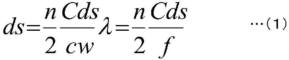
- an acoustic transmission member with a planar shape having a predetermined acoustic frequency band as a transmission frequency band the acoustic transmission member including a core layer layered between two skin layers, wherein the skin layers are formed of a material having a higher elastic modulus than a material of the core layer, and a thickness ds of the skin layers satisfying Equation (1), where f is a center frequency of the transmission frequency band, cw is an acoustic velocity in a medium surrounding the acoustic transmission member, ⁇ is a wavelength corresponding to the center frequency in the medium, cds is a longitudinal wave acoustic velocity in the skin layers, and n is a discretionary natural number.
- the skin layer is formed of a material having an elastic modulus from 100 MPa to 350 GPa.
- the skin layer is formed by including any one of fiber reinforced plastic, plastic, and metal.
- the core layer is formed of a viscoelastic member or plastic.
- the core layer is formed to have a density and elastic modulus being at predetermined values by injecting glass microballoons into the viscoelastic member or the plastic.
- a difference between an acoustic impedance of a material forming the core layer is within a range of ⁇ 50% of an acoustic impedance of the medium.
- the medium is a liquid
- a material forming the core layer is a liquid having an acoustic impedance within a range of ⁇ 50% of an acoustic impedance of the liquid.
- a thickness dc of the core layer and the wavelength ⁇ satisfy 0.0675 ⁇ dc/ ⁇ ⁇ 5.4.
- a protective layer is formed on a surface of the skin layer.
- a method of designing an acoustic transmission member according to the invention of claim 10 is provided, the acoustic transmission member having a planar shape, including a core layer layered between two skin layers, and having a first acoustic frequency band as a transmission frequency band and a second acoustic frequency band as a shielded frequency band, the method including:
- a method of designing an acoustic transmission member according to the invention of claim 11 is provided, the acoustic transmission member having a planar shape, including a core layer layered between two skin layers, having a predetermined acoustic frequency band as a transmission frequency band, and a predetermined required strength and rigidity, the method including:
- a thickness dc of the core layer and the wavelength ⁇ satisfy 0.0675 ⁇ dc/ ⁇ ⁇ 5.4.
- the skin layers are formed of a material having a higher elastic modulus than a material of the core layer.
- the skin layers have a half-wavelength structure, allowing the acoustic transmission member to be formed with good transmission characteristics at a center frequency irrespective of the thickness of the core layer and is advantageous in that the degree of freedom in designing the acoustic transmission member is improved. Additionally, this is advantageous in that a certain wide transmission band can be ensured at a center frequency, and is adaptable to temperature change in the surrounding medium due to temperature change. Furthermore, the function of shielding acoustic waves outside of the center frequency is provided. This is advantageous in that noise resistance of the acoustic transmission member is improved.
- the skin layer and the intermediate layer can be formed of various materials.
- the core layer can be formed having any density and elastic modulus.
- reflection at the boundary can be reduced and acoustic transmission characteristics can be improved.
- the same type of fluid with the fluid surrounding the acoustic transmission member can be used as core layer. This is advantageous in that the difference in acoustic impedance between the surrounding fluid and the core layer can be decreased.
- an acoustic transmission member having good transmission characteristics at a center frequency can be formed more reliably.
- the protective layer can reduce the effect of pressure from the surrounding medium and the effect of marine organisms, and improve the strength of the acoustic transmission member.
- an acoustic transmission member can be formed in that the skin layers have a half-wavelength structure to provide good transmission characteristics at a discretionary frequency band, also has good shielding characteristics at a discretionary frequency band due to the thickness of the core layer being able to be adjusted.
- an acoustic transmission member can be formed in that the skin layers have a half-wavelength structure to provide good transmission characteristics at a discretionary frequency band, also has a desired strength and rigidity due to the thickness of the core layer being able to be adjusted.
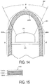
- FIG. 14 is an explanatory diagram illustrating a configuration of a marine sonar device 20 installed with an acoustic transmission member.
- the acoustic transmission member according to the present invention is used in order to form an acoustic transmission region ⁇ in the sonar device 20, for example.
- the sonar device 20 is disposed at a leading end of a sonar device support platform (not illustrated) provided to the body of a vessel.
- the sonar device 20 includes a transducer 24 and an acoustic window 26.
- the transducer 24 is mounted on a frame 28 made of fiber reinforced plastics (FRP) supported in an inside potion surrounded by the acoustic window 26, and is disposed towards the front direction of the vessel.
- FRP fiber reinforced plastics
- the acoustic window 26 is configured to protect the transducer 24 and is provided so as to cover the transducer 24, with water filling the inside portion surrounded by the acoustic window 26.
- the acoustic window 26 has a cylindrical portion 26A, and a curved surface portion 26B that is formed in a curved shape that protrudes toward the front from the tip of the cylindrical portion 26A.
- the frame 28 on which the transducer 24 is mounted is supported in the inside portion surrounded by the cylindrical portion 26A.
- the acoustic window 26 has the acoustic transmission region ⁇ that enables acoustic transmission, and an acoustic insulation region ⁇ that blocks sound.
- the curved surface portion 26B of the acoustic window 26 that constitutes the acoustic transmission region ⁇ is made of the acoustic transmission member according to the present invention.
- the cylindrical portion 26A of the acoustic window 26 constituting the acoustic insulation region ⁇ is constituted of an acoustic insulating material that blocks sound (this includes reducing oscillation noise).
- acoustic insulating material various known materials can be used such as a viscoelastic member (air bubbles dispersion type acoustic insulating material) such as rubber or polyurethane with air bubbles (vinyl-based microballoons) mixed in, or a material in which thin rubber plates sandwiching a thin rubber plate with many small holes provided therethrough (air hole-type acoustic insulating material) on both surfaces.
- the acoustic transmission region ⁇ is the entirety of the curved surface portion 26B excluding edge portions of the curved surface portion 26B that are located near the cylindrical portion 26A, and a range ⁇ illustrated in FIG. 14 is the range in which the transducer 24 searches for obstacles in the front such as whales and driftwood.
- FIG. 1 is a cross-sectional view illustrating a configuration of an acoustic transmission member 10 according to an embodiment.
- the acoustic transmission member 10 is illustrated as having a planar shape, but the acoustic transmission member 10 can be molded in any shape depending on the application.
- the acoustic transmission member 10 has a planar shape and acoustic transmission properties.
- the acoustic transmission member 10 has a predetermined acoustic frequency band as a transmission frequency band, with f defined as the center frequency of the transmission frequency band.
- the acoustic transmission member 10 includes a core layer 104 layered between two skin layers 102A, 102B. More specifically, the skin layer 102A, the core layer 104, and the skin layer 102B are layered in the described order from the upper side of FIG. 1 .
- Protective layers may further be provided on the surfaces of the skin layers 102A, 102B, that is, the surfaces of the two skin layers 102A, 102B opposite to the surfaces bonding the core layer 104. Such protective layers are provided in order to protect the sonar device 20 from external loads or to evade from marine organisms, for example. Additionally, a protective layer may be provided on only on surface of one of the skin layers 102A, 102B.
- the skin layers 102A, 102B are formed of a material with a higher elastic modulus than the core layer 104.
- the skin layers 102A, 102B are formed of a material with an elastic modulus from 100 MPa to 350 GPa, for example. This is because the material having an elastic modulus of less than 100 MPa makes it difficult to maintain the layers as structural members, and the material having an elastic modulus of greater than 350 GPa has too high of an acoustic impedance.
- the skin layers 102A, 102B can specifically be formed using any of fiber reinforced plastics (FRP, glass fiber reinforced plastics (GFRP), carbon fiber reinforced plastics (CFRP), or the like), plastic, or metal (copper, titanium, or the like).
- the core layer 104 is formed of a viscoelastic member such as rubber or polyurethane, or plastic, for example.
- the core layer 104 may be formed to have a density and elastic modulus being at desired values (predetermined values) by injecting glass microballoons into the above-described viscoelastic member or plastic.
- the difference in acoustic impedance between the material forming the core layer 104 and the medium surrounding the acoustic transmission member 10 be within a range of ⁇ 50%.
- the acoustic impedance is calculated as the product pc of a material density ⁇ and a longitudinal wave acoustic velocity c.
- the acoustic impedance of the material forming the core layer 104 is calculated as a product ⁇ 1c1 of a density ⁇ 1 of the material forming the core layer 104 and the longitudinal wave acoustic velocity c1 in the material forming the core layer 104.
- the acoustic impedance of the medium surrounding the acoustic transmission member 10 is calculated as a product ⁇ 2c2 of a density ⁇ 2 of the medium surrounding the acoustic transmission member 10 and the longitudinal wave acoustic velocity c2 in the same medium. It is preferable that the density and elastic modulus of the core layer 104 be adjusted such that the difference between the acoustic impedance ⁇ 1c1 of the material forming the core layer 104 and the acoustic impedance ⁇ 2c2 of the medium surrounding the acoustic transmission member 10 is within a range of ⁇ 50%.
- the medium surrounding the acoustic transmission member 10 is a liquid such as fresh water or seawater.
- the material constituting the core layer 104 may be a liquid with a difference in acoustic impedance within range of ⁇ 50% of the acoustic impedance of the surrounding fluid, specifically, the same type of liquid as the surrounding fluid.
- fresh water, sea water, or the like being the surrounding fluid may be inserted between the skin layers 102A, 102B to form the core layer 104.
- fresh water is preferably used to reduce the chances of corrosion and the like.
- a thickness ds of the skin layers 102A, 102B is formed such that Equation (1) below is satisfied, where f is the center frequency of the transmission frequency band of the acoustic transmission member 10, cw is the acoustic velocity in the medium surrounding the acoustic transmission member 10, ⁇ is the wavelength corresponding to the center frequency f in the medium, cds is the longitudinal wave acoustic velocity in the skin layer, and n is a discretionary natural number.
- the skin layers 102A, 102B that satisfy Equation (1) above take a half-wavelength structure with respect to the center frequency to minimize acoustic transmission loss.
- the acoustic transmission member 10 can be formed with good transmission characteristics with respect to the transmission frequency band irrespective of the thickness of the core layer 104.
- the thickness dc of the core layer 104 is preferably set in relation to the wavelength ⁇ corresponding to the center frequency f in the medium to satisfy 0.05 ⁇ dc/ ⁇ ⁇ 5.4.
- the present inventors determined that by satisfying the range described above allows good acoustic transmission characteristics to be achieved.
- CFRP prepreg C3WPW/F-6986
- natural rubber F-9099 was used for the core layer 104.
- the materials and constants of the materials are listed in FIG. 2 .
- the longitudinal wave acoustic velocity in the CFRP i.e., the skin layers 102A, 102B
- the vertical axis indicates longitudinal wave acoustic velocity in the CFRP
- the horizontal axis indicates frequency (kHz).
- the acoustic velocity in the CFRP is assumed to have the frequency characteristics. Specifically, it is assumed to be 1830 m/s at 50 kHz and 2900 m/s at 500 kHz, for example.
- FIG. 4 is a graph showing the transmission loss (IL) of a single layer plate of the CFRP (skin layers 102A, 102B) for acoustic waves of 50 kHz.
- the vertical axis indicates transmission loss (dB) and the horizontal axis indicates thickness of the CFRP plate (mm).
- the CFRP plate has a thickness whereby transmission loss periodically decreases.
- FIG. 5 is a graph showing the transmission loss (IL) of the acoustic transmission members 10 of examples with various core layer thicknesses and a fixed skin layer thickness.
- the vertical axis indicates transmission loss (dB), and the horizontal axis indicates frequency (kHz).
- each of the acoustic transmission members 10 has properties by which sounds in a frequency band with a small transmission loss are transmitted, and sounds in a frequency band with a large transmission loss cut-off.
- the acoustic transmission members 10 in which the thickness of the skin layers 102A, 102B was 18 mm achieve good transmission characteristics at or near 50 kHz irrespective of the thickness of the core layer 104. Also, as seen from the characteristics curve, the transmission loss is high each on the low frequency side and the high frequency side of the center frequency, i.e., 50 kHz. This has the effect of shielding acoustic waves in bands outside of the center frequency.
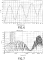
- FIG. 6 is a graph showing the transmission loss (IL) of a single layer plate of the CFRP (skin layers 102A, 102B) with respect to acoustic waves of 500 kHz.
- the vertical axis indicates transmission loss (dB) and the horizontal axis indicates thickness of the CFRP plate (mm).
- FIG. 7 is a graph showing the transmission loss characteristics of the acoustic transmission members 10 of examples with various core layer thicknesses and the skin layer thickness fixed at 3 mm.
- FIG. 8 is a graph showing the transmission loss characteristics of the acoustic transmission members 10 of examples with various core layer thicknesses and the skin layer thickness fixed at 2.5 mm. Note that in FIGS. 7 and 8 , the thickness of the core layer 104 ranges from 0.5 mm to 10 mm in 1 mm increments.
- the thickness of the CFRP plate to obtain a minimal value for transmission loss with the acoustic waves at 500 kHz is 2.9 mm.
- the trough of the minimal value is not on 500 kHz in both FIG. 7 (3 mm) and FIG. 8 (2.5 mm).
- FIGS. 9 to 11 it can be seen that as the thickness of the CFRP plate decreases, the trough of the minimal value moves toward higher frequencies, validifying Equation (1).
- the trough of the minimal value is in a section very close to 500 kHz.
- the thickness of the core layer 104 can be adjusted to obtain sufficient transmission performance at the center frequency.
- a CFRP plate with a thickness of 3 mm like that of FIG. 7 or a CFRP plate with a thickness of 2.5 mm can be used to form an acoustic transmission member 10 with a center frequency of 500 kHz.
- FIG. 12 is a table listing the transmission loss (unit: dB) at 500 kHz of the acoustic transmission members 10 formed using a CFRP plate with a thickness of 2.5 mm and a CFRP plate with a thickness of 3.0 mm. From FIG. 12 , the following six configurations resulting in a transmission loss of 2 dB or less is extracted: (skin layer thickness/core layer thickness) 2.5 mm/1.0 mm, 3.0 mm/0.5 mm, 3.0 mm/1.0 mm, 3.0 mm/2.0 mm, 3.0 mm/3.0 mm, 3.0 mm/4.0 mm.
- FIG. 13 is a graph showing transmission characteristics of the acoustic transmission members 10 with good transmission characteristics at 500 kHz extracted from FIG. 12 .
- the combination of skin layer thickness 3.0 mm/core layer 0.5 mm is the best of this group.
- the transmission loss at from 450 kHz to 540 kHz is 2 dB or less
- the high transmission bandwidth with a transmission loss of 2 dB or less is 18%.
- values near but outside of the value calculated using Equation (1) for the skin layer thickness can be used in combination with adjusting the core layer thickness to form an acoustic transmission member 10 having sufficiently high transmission performance.
- FIGS. 9 to 11 are graphs showing the transmission loss of the acoustic transmission members 10 of examples with various core layer thicknesses and a fixed skin layer of 2 mm for FIG. 9 , a fixed skin layer of 1.5 mm for FIG. 10 , and a fixed skin layer of 1 mm for FIG. 11 .
- the thickness of the core layer 104 ranges from 0.5 mm to 10 mm in 1 mm increments.
- the trough of the minimal value is at or near 800 kHz.
- the frequency at which the trough of the minimal value (transmission window) is formed is 1000 kHz or less, making the trough of the minimal value not seen in the drawings.
- the skin layer thickness is fixed at 18 mm and the thickness dc of the core layer 104 ranges from 2 mm to 20 mm. Additionally, when the acoustic velocity in the surrounding medium (water in the present embodiment) is 1481 m/s, the wavelength ⁇ corresponding to a center frequency of 50 kHz is 29.6 mm. Thus, the range of dc/ ⁇ in FIG. 5 is from 0.0675 (2 mm) to 0.675 (20 mm).
- the skin layer thickness is fixed at 2 mm and the thickness dc of the core layer 104 ranges from 0.5 mm to 10 mm. Additionally, when the acoustic velocity in the surrounding medium (water in the present embodiment) is 1481 m/s, the wavelength ⁇ corresponding to a center frequency of 800 kHz is 1.85 mm. Thus, the range of dc/ ⁇ in FIG. 10 is from 0.27 (0.5 mm) to 5.4 (10 mm).
- the thickness of the core layer 104 may be determined as follows, for example.
- the acoustic transmission member 10 of the present embodiment has a consistently small transmission loss at or near the center frequency. However, in frequency bands outside of the center frequency, the transmission loss performance varies greatly depending on the thickness of the core layer 104. In other words, the maximal value of the transmission loss varies with the thickness of the core layer 104. Thus, by selecting a core layer thickness with the maximal value of transmission loss located at or near the desired cut-off frequency band, an acoustic transmission member 10 having desired transmission performance including cut-off performance can be formed.
- designing an acoustic transmission member having a predetermined transmission frequency band and shielded frequency band includes a skin layer thickness determining step of determining the thickness ds of the skin layers 102A, 102B using Equation (1) above, a transmission loss measuring step of measuring or calculating the transmission loss of an each layer formed by layering the core layer 104 of varying thickness successively between the skin layers 102A, 102B with the thickness determined in the skin layer thickness determining step, and a core layer thickness determining step of determining the thickness of the core layer 104 with the maximal value of transmission loss, among the transmission losses measured or calculated in a previous step, being located closest to the center frequency of the shielded frequency band as a thickness of the core layer 104 of the acoustic transmission member 10.
- An acoustic transmission member having desired transmission performance and cut-off performance can be designed with this method.
- the acoustic transmission member 10 includes the skin layers 102A, 102B with a half-wavelength structure, allowing the acoustic transmission member 10 to be formed with good transmission characteristics at a center frequency irrespective of the thickness of the core layer 104 and is advantageous in that the degree of freedom in designing the acoustic transmission member 10 is improved. Additionally, the acoustic transmission member 10 is advantageous in that a certain wide transmission band can be ensured at a center frequency, and is adaptable to temperature change in the surrounding medium due to temperature change. Furthermore, the acoustic transmission member 10 has the function of shielding acoustic waves outside of the center frequency. This is advantageous in that noise resistance is improved.
Landscapes
- Engineering & Computer Science (AREA)
- Physics & Mathematics (AREA)
- Mechanical Engineering (AREA)
- Remote Sensing (AREA)
- Radar, Positioning & Navigation (AREA)
- Acoustics & Sound (AREA)
- Chemical & Material Sciences (AREA)
- Computer Networks & Wireless Communication (AREA)
- General Physics & Mathematics (AREA)
- Combustion & Propulsion (AREA)
- Ocean & Marine Engineering (AREA)
- Multimedia (AREA)
- Signal Processing (AREA)
- Composite Materials (AREA)
- Laminated Bodies (AREA)
- Measurement Of Velocity Or Position Using Acoustic Or Ultrasonic Waves (AREA)
- Soundproofing, Sound Blocking, And Sound Damping (AREA)
Abstract
Description
- The present invention relates to an acoustic transmission member having acoustic transmission properties and a method of designing the same.
- In the related art, acoustic transmission members having acoustic transmission properties have been used for an acoustic transmission region of a device such as a marine sonar. A member formed of steel is a typical example of a known acoustic transmission member, but rubber acoustic transmission members such as rubber domes or rubber windows are known as an enhanced structure for the conventional acoustic transmission members. Such known acoustic transmission members are essentially single layer structures with excellent acoustic transmission characteristics in the low frequency region of a few kHz or less, but are difficult to use in a high frequency band of 20 kHz or greater.
- In
Patent Document 1 below, an acoustic transmission member that employs a sandwich structure in which both surfaces of a core layer are covered by skin layers is described.
FIG. 15 is an explanatory diagram illustrating a structure of the acoustic transmission member according toPatent Document 1. In anacoustic transmission member 130 illustrated inFIG. 15 , natural rubber having a thickness of 5 mm is used for thecore layer 1302, and carbon fiber reinforced plastics (CFRP) having a thickness of 2 mm is used for theskin layers 1304.
According to this structure, it is possible to form an acoustic transmission member that transmits, in addition to frequencies of the low frequency region where known acoustic transmission members can attain acoustic transmission properties, a frequency f that satisfies Equations (2) and (3) below as the center frequency of a predetermined frequency band. In Equations (2) and (3) below, dc denotes the thickness of thecore layer 1302, C denotes the acoustic velocity in thecore layer 1302, and CO denotes the acoustic velocity of the surrounding medium.

- In
Patent Document 2 below, an acoustic transmission member that includes N + 1 layers of core layers and an N layers of intermediate layers being alternately layered between two skin layers is described.
FIG. 17 is an explanatory diagram illustrating a structure of the acoustic transmission member according toPatent Document 2. In acoustic transmission members A, B, C in which the N is 1, 2, 3, respectively illustrated inFIG. 17 , natural rubber is used for the core layers, and carbon fiber reinforced plastics (CFRP) is used for the skin layers and the intermediate layer, respectively. -
- Patent Document 1:
US 4,997,705 - Patent Document 2:
JP 2015-098086 A - A viscoelastic member such as rubber or urethane is used for the core layer of the
acoustic transmission member 130 according toPatent Document 1 illustrated inFIG. 15 . Such a viscoelastic member has temperature characteristics, and depending on the change in temperature, the acoustic velocity in the viscoelastic member (C in Equation (2) described above) also changes. The acoustic velocity in the surrounding medium (C0 in Equation (2) described above) also changes depending on the temperature. As a result, the frequency f indicated in Equation (3) described above shifts due to the temperature, resulting in a large impact on system performance. -
FIG. 16 is a graph showing transmission characteristics of the acoustic transmission member illustrated inFIG. 15 .
InFIG. 16 , the vertical axis indicates transmission loss IL, and the horizontal axis indicates frequency. In the graph,reference sign 1402 denotes values obtained by actual measurement about acoustic transmission characteristics of the acoustic transmission member illustrated inFIG. 15 in 20°C water.Reference sign 1404 denotes calculated values obtained by modeling acoustic transmission characteristics in 20°C water according to the actually measured values denoted byreference sign 1402, andreference sign 1406 denotes values obtained by calculating the acoustic transmission characteristics in 16°C water on the basis of the calculated values indicated byreference sign 1404. - It is estimated that a temperature change by 4°C from 20°C to 16°C causes the acoustic velocity to fluctuate by 15%, and as a result, it is estimated that a window region of a high frequency region shifts by 15% as denoted by
reference signs FIG. 16 is 0.6 dB (1 dB or less) at a water temperature of 20°C, but increases to 3.5 dB at a water temperature of 16°C. Such a change in characteristics has a large impact on system performance.
Accordingly, the technology ofPatent Document 1 described above is capable of expanding the transmission bandwidth in the acoustic transmission member, but cannot attain a practically sufficient (adaptable to change in characteristics due to temperature change as described above) bandwidth in the high frequency band. -
FIG. 18 is a graph showing transmission characteristics of the acoustic transmission members (Patent Document 2) illustrated inFIG. 17 . InFIG. 18 , the vertical axis indicates transmission loss IL, and the horizontal axis indicates frequency.
As illustrated inFIG. 18 , the acoustic transmission members A, B, C according toPatent Document 2 has superior acoustic transmission characteristics even in the high frequency band compared to simple sandwich structures (A sandwich structure) such as C1.
However, the acoustic transmission members A, B, C according toPatent Document 2 have a thin film structure that does not allow the necessary strength and rigidity to be easily ensured. Increasing strength and rigidity via multilayering has been considered, but this increases manufacture difficulties and cost.
Additionally, to exhibit uniformly good acoustic transmission characteristics in the frequency band to use, external noise is transmitted in a frequency band lower than the frequency band to use. This may cause deterioration in the noise resistance of the system. - In light of the above-described problem of the existing technology, an object of the present invention is to provide an acoustic transmission member that provides a wide acoustic transmission band suitable for a high frequency region and ensures a certain strength.
- To solve the problem described above and achieve the object, provided is an acoustic transmission member with a planar shape having a predetermined acoustic frequency band as a transmission frequency band, the acoustic transmission member including a core layer layered between two skin layers, wherein the skin layers are formed of a material having a higher elastic modulus than a material of the core layer, and a thickness ds of the skin layers satisfying Equation (1),
where f is a center frequency of the transmission frequency band, cw is an acoustic velocity in a medium surrounding the acoustic transmission member, λ is a wavelength corresponding to the center frequency in the medium, cds is a longitudinal wave acoustic velocity in the skin layers, and n is a discretionary natural number.
- In the acoustic transmission member according to the invention of
claim 2, the skin layer is formed of a material having an elastic modulus from 100 MPa to 350 GPa.
In the acoustic transmission member according to the invention ofclaim 3, the skin layer is formed by including any one of fiber reinforced plastic, plastic, and metal.
In the acoustic transmission member according to the invention ofclaim 4, the core layer is formed of a viscoelastic member or plastic.
In the acoustic transmission member according to the invention ofclaim 5, the core layer is formed to have a density and elastic modulus being at predetermined values by injecting glass microballoons into the viscoelastic member or the plastic.
In the acoustic transmission member according to the invention ofclaim 6, a difference between an acoustic impedance of a material forming the core layer is within a range of ±50% of an acoustic impedance of the medium. In the acoustic transmission member according to the invention ofclaim 7, the medium is a liquid, and
a material forming the core layer is a liquid having an acoustic impedance within a range of ±50% of an acoustic impedance of the liquid.
In the acoustic transmission member according to the invention ofclaim 8, a thickness dc of the core layer and the wavelength λ satisfy 0.0675 ≤ dc/λ ≤ 5.4.
In the acoustic transmission member according to the invention ofclaim 9, a protective layer is formed on a surface of the skin layer.
A method of designing an acoustic transmission member according to the invention ofclaim 10 is provided, the acoustic transmission member having a planar shape, including a core layer layered between two skin layers, and having a first acoustic frequency band as a transmission frequency band and a second acoustic frequency band as a shielded frequency band, the method including: - a skin layer thickness determining step of determining a thickness ds of the skin layers using Equation (1); a transmission loss measuring step of measuring or calculating transmission losses of each layer formed by layering a core layer having varied thickness, successively on the skin layers with a thickness determined in the skin layer thickness determining step; and a core layer thickness determining step of determining a thickness of a core layer with a maximal value of transmission loss, among the transmission losses measured or calculated, being closest to a center frequency of a shielded frequency band as a thickness of the core layer of the acoustic transmission member,
- in Equation (1), f is a center frequency of the transmission frequency band, cw is an acoustic velocity in a medium surrounding the acoustic transmission member, λ is a wavelength corresponding to the center frequency in the medium, cds is a longitudinal wave acoustic velocity in the skin layers, and n is a discretionary natural number.
- A method of designing an acoustic transmission member according to the invention of
claim 11 is provided, the acoustic transmission member having a planar shape, including a core layer layered between two skin layers, having a predetermined acoustic frequency band as a transmission frequency band, and a predetermined required strength and rigidity, the method including: - a skin layer thickness determining step of determining a thickness ds of the skin layers using Equation (1); and
- a core layer thickness determining step of calculating a thickness of the core layer having strength satisfying the required strength and rigidity when layered between the skin layers with a thickness determined in the skin layer thickness determining step,
- where in Formula (1), f is a center frequency of the transmission frequency band, cw is an acoustic velocity in a medium surrounding the acoustic transmission member, λ is a wavelength corresponding to the center frequency in the medium, cds is a longitudinal wave acoustic velocity in the skin layers, and n is a discretionary natural number.
- In the method of designing an acoustic transmission member according to the invention of
claim 12, a thickness dc of the core layer and the wavelength λ satisfy 0.0675 ≤ dc/λ ≤ 5.4.
In the method of designing an acoustic transmission member according to the invention ofclaim 13, the skin layers are formed of a material having a higher elastic modulus than a material of the core layer. - According to the invention of
claim 1, the skin layers have a half-wavelength structure, allowing the acoustic transmission member to be formed with good transmission characteristics at a center frequency irrespective of the thickness of the core layer and is advantageous in that the degree of freedom in designing the acoustic transmission member is improved. Additionally, this is advantageous in that a certain wide transmission band can be ensured at a center frequency, and is adaptable to temperature change in the surrounding medium due to temperature change. Furthermore, the function of shielding acoustic waves outside of the center frequency is provided. This is advantageous in that noise resistance of the acoustic transmission member is improved.
According to the invention ofclaim 2, the skin layer and the intermediate layer can be formed of various materials.
According to the invention ofclaim 3, excellent acoustic transmission characteristics can be obtained and strength of the acoustic transmission member can be ensured.
According to the invention ofclaim 4, excellent acoustic transmission characteristics can be obtained and strength of the acoustic transmission member can be ensured.
According to the invention ofclaim 5, the core layer can be formed having any density and elastic modulus.
According to the invention ofclaim 6, reflection at the boundary can be reduced and acoustic transmission characteristics can be improved.
According to the invention ofclaim 7, the same type of fluid with the fluid surrounding the acoustic transmission member can be used as core layer. This is advantageous in that the difference in acoustic impedance between the surrounding fluid and the core layer can be decreased.
The inventions ofclaims
According to the invention ofclaim 9, the protective layer can reduce the effect of pressure from the surrounding medium and the effect of marine organisms, and improve the strength of the acoustic transmission member. According to the invention ofclaim 10, an acoustic transmission member can be formed in that the skin layers have a half-wavelength structure to provide good transmission characteristics at a discretionary frequency band, also has good shielding characteristics at a discretionary frequency band due to the thickness of the core layer being able to be adjusted. According to the invention ofclaim 11, an acoustic transmission member can be formed in that the skin layers have a half-wavelength structure to provide good transmission characteristics at a discretionary frequency band, also has a desired strength and rigidity due to the thickness of the core layer being able to be adjusted. -
-
FIG. 1 is a cross-sectional view illustrating a configuration of anacoustic transmission member 10 according to an embodiment. -
FIG. 2 is a table listing material constants of each material for formingskin layers core layer 104. -
FIG. 3 is a graph showing frequency characteristics of the longitudinal wave acoustic velocity in a carbon fiber reinforced plastic (CFRP). -
FIG. 4 is a graph showing transmission loss characteristics of a single layer plate of the CFRP for acoustic waves of 50 kHz. -
FIG. 5 is a graph showing transmission loss characteristics ofacoustic transmission members 10 with a skin layer thickness of 18 mm. -
FIG. 6 is a graph showing transmission loss characteristics of a single layer plate of the CFRP for acoustic waves of 500 kHz. -
FIG. 7 is a graph showing transmission loss characteristics ofacoustic transmission members 10 with a skin layer thickness of 3 mm. -
FIG. 8 is a graph showing transmission loss characteristics ofacoustic transmission members 10 with a skin layer thickness of 2.5 mm. -
FIG. 9 is a graph showing transmission loss characteristics ofacoustic transmission members 10 with a skin layer thickness of 2 mm. -
FIG. 10 is a graph showing transmission loss characteristics ofacoustic transmission members 10 with a skin layer thickness of 1.5 mm. -
FIG. 11 is a graph showing transmission loss characteristics ofacoustic transmission members 10 with a skin layer thickness of 1 mm. -
FIG. 12 is a table listing the transmission loss at 500 kHz of theacoustic transmission members 10 with a skin layer thickness of 2.5 mm and 3.0 mm. -
FIG. 13 is a graph showing transmission characteristics of theacoustic transmission members 10 with good transmission characteristics at 500 kHz extracted fromFIG. 12 . -
FIG. 14 is an explanatory diagram illustrating a configuration of amarine sonar device 20 installed with an acoustic transmission member. -
FIG. 15 is an explanatory drawing illustrating a structure of an acoustic transmission member according to ExistingTechnology 1. -
FIG. 16 is a graph showing transmission characteristics of the acoustic transmission member illustrated inFIG. 15 . -
FIG. 17 is an explanatory drawing illustrating a structure of an acoustic transmission member according to ExistingTechnology 2. -
FIG. 18 is a graph showing transmission characteristics of the acoustic transmission member illustrated inFIG. 17 . - Acoustic transmission members according to preferred embodiments of the present invention are described in detail below with reference to the accompanying drawings.
FIG. 14 is an explanatory diagram illustrating a configuration of amarine sonar device 20 installed with an acoustic transmission member. The acoustic transmission member according to the present invention is used in order to form an acoustic transmission region α in thesonar device 20, for example.
Thesonar device 20 is disposed at a leading end of a sonar device support platform (not illustrated) provided to the body of a vessel.
Thesonar device 20 includes atransducer 24 and anacoustic window 26. Thetransducer 24 is mounted on aframe 28 made of fiber reinforced plastics (FRP) supported in an inside potion surrounded by theacoustic window 26, and is disposed towards the front direction of the vessel. - The
acoustic window 26 is configured to protect thetransducer 24 and is provided so as to cover thetransducer 24, with water filling the inside portion surrounded by theacoustic window 26.
Theacoustic window 26 has acylindrical portion 26A, and acurved surface portion 26B that is formed in a curved shape that protrudes toward the front from the tip of thecylindrical portion 26A.
Theframe 28 on which thetransducer 24 is mounted is supported in the inside portion surrounded by thecylindrical portion 26A. - The
acoustic window 26 has the acoustic transmission region α that enables acoustic transmission, and an acoustic insulation region β that blocks sound.
Thecurved surface portion 26B of theacoustic window 26 that constitutes the acoustic transmission region α is made of the acoustic transmission member according to the present invention.
Thecylindrical portion 26A of theacoustic window 26 constituting the acoustic insulation region β is constituted of an acoustic insulating material that blocks sound (this includes reducing oscillation noise). As such an acoustic insulating material, various known materials can be used such as a viscoelastic member (air bubbles dispersion type acoustic insulating material) such as rubber or polyurethane with air bubbles (vinyl-based microballoons) mixed in, or a material in which thin rubber plates sandwiching a thin rubber plate with many small holes provided therethrough (air hole-type acoustic insulating material) on both surfaces. In the present embodiment, the acoustic transmission region α is the entirety of thecurved surface portion 26B excluding edge portions of thecurved surface portion 26B that are located near thecylindrical portion 26A, and a range θ illustrated inFIG. 14 is the range in which thetransducer 24 searches for obstacles in the front such as whales and driftwood. - Next, the acoustic transmission member constituting the acoustic transmission region α will be described.
FIG. 1 is a cross-sectional view illustrating a configuration of anacoustic transmission member 10 according to an embodiment.
In the description below, for ease of explanation, theacoustic transmission member 10 is illustrated as having a planar shape, but theacoustic transmission member 10 can be molded in any shape depending on the application.
Theacoustic transmission member 10 has a planar shape and acoustic transmission properties. Theacoustic transmission member 10 has a predetermined acoustic frequency band as a transmission frequency band, with f defined as the center frequency of the transmission frequency band. Theacoustic transmission member 10 includes acore layer 104 layered between twoskin layers skin layer 102A, thecore layer 104, and theskin layer 102B are layered in the described order from the upper side ofFIG. 1 . - Protective layers may further be provided on the surfaces of the skin layers 102A, 102B, that is, the surfaces of the two
skin layers core layer 104. Such protective layers are provided in order to protect thesonar device 20 from external loads or to evade from marine organisms, for example.
Additionally, a protective layer may be provided on only on surface of one of the skin layers 102A, 102B. - Next, the materials of the respective layers will be described.
The skin layers 102A, 102B are formed of a material with a higher elastic modulus than thecore layer 104.
The skin layers 102A, 102B are formed of a material with an elastic modulus from 100 MPa to 350 GPa, for example. This is because the material having an elastic modulus of less than 100 MPa makes it difficult to maintain the layers as structural members, and the material having an elastic modulus of greater than 350 GPa has too high of an acoustic impedance.
The skin layers 102A, 102B can specifically be formed using any of fiber reinforced plastics (FRP, glass fiber reinforced plastics (GFRP), carbon fiber reinforced plastics (CFRP), or the like), plastic, or metal (copper, titanium, or the like). - Also, the
core layer 104 is formed of a viscoelastic member such as rubber or polyurethane, or plastic, for example.
Thecore layer 104 may be formed to have a density and elastic modulus being at desired values (predetermined values) by injecting glass microballoons into the above-described viscoelastic member or plastic. - It is preferable that the difference in acoustic impedance between the material forming the
core layer 104 and the medium surrounding the acoustic transmission member 10 (fresh water or seawater in the present embodiment) be within a range of ±50%.
Specifically, the acoustic impedance is calculated as the product pc of a material density ρ and a longitudinal wave acoustic velocity c. In other words, the acoustic impedance of the material forming thecore layer 104 is calculated as a product ρ1c1 of a density ρ1 of the material forming thecore layer 104 and the longitudinal wave acoustic velocity c1 in the material forming thecore layer 104. The acoustic impedance of the medium surrounding theacoustic transmission member 10 is calculated as a product ρ2c2 of a density ρ2 of the medium surrounding theacoustic transmission member 10 and the longitudinal wave acoustic velocity c2 in the same medium.
It is preferable that the density and elastic modulus of thecore layer 104 be adjusted such that the difference between the acoustic impedance ρ1c1 of the material forming thecore layer 104 and the acoustic impedance ρ2c2 of the medium surrounding theacoustic transmission member 10 is within a range of ±50%.
This is because when the difference between the acoustic impedance ρ1c1 of the material forming thecore layer 104 and the acoustic impedance ρ2c2 of the medium surrounding theacoustic transmission member 10 is too great, the boundary becomes highly reflective, reducing the acoustic transmission properties. - In the present embodiment, the medium surrounding the
acoustic transmission member 10 is a liquid such as fresh water or seawater. Accordingly, the material constituting thecore layer 104 may be a liquid with a difference in acoustic impedance within range of ±50% of the acoustic impedance of the surrounding fluid, specifically, the same type of liquid as the surrounding fluid.
In other words, fresh water, sea water, or the like being the surrounding fluid may be inserted between the skin layers 102A, 102B to form thecore layer 104. Note that in a configuration in which the surrounding fluid is sea water, fresh water is preferably used to reduce the chances of corrosion and the like. - Next, the thicknesses of the respective layers will be described.
A thickness ds of the skin layers 102A, 102B is formed such that Equation (1) below is satisfied, where f is the center frequency of the transmission frequency band of theacoustic transmission member 10, cw is the acoustic velocity in the medium surrounding theacoustic transmission member 10, λ is the wavelength corresponding to the center frequency f in the medium, cds is the longitudinal wave acoustic velocity in the skin layer, and n is a discretionary natural number.
- The skin layers 102A, 102B that satisfy Equation (1) above take a half-wavelength structure with respect to the center frequency to minimize acoustic transmission loss. By selecting such a thickness, the
acoustic transmission member 10 can be formed with good transmission characteristics with respect to the transmission frequency band irrespective of the thickness of thecore layer 104. - The thickness dc of the
core layer 104 is preferably set in relation to the wavelength λ corresponding to the center frequency f in the medium to satisfy 0.05 < dc/λ < 5.4.
In varying the thickness dc of thecore layer 104 as described below, the present inventors determined that by satisfying the range described above allows good acoustic transmission characteristics to be achieved. - The characteristics of acoustic transmission members according to the present invention will be described in detail below.
In the examples below, CFRP (prepreg C3WPW/F-6986) was used for the skin layers 102A, 102B, and natural rubber F-9099 was used for thecore layer 104. The materials and constants of the materials are listed inFIG. 2 . Additionally, the longitudinal wave acoustic velocity in the CFRP, i.e., the skin layers 102A, 102B, is shown inFIG. 3 . The vertical axis indicates longitudinal wave acoustic velocity in the CFRP, and the horizontal axis indicates frequency (kHz). The acoustic velocity in the CFRP is assumed to have the frequency characteristics. Specifically, it is assumed to be 1830 m/s at 50 kHz and 2900 m/s at 500 kHz, for example. - First, the
acoustic transmission member 10 with a center frequency of 50 kHz will be discussed.
FIG. 4 is a graph showing the transmission loss (IL) of a single layer plate of the CFRP (skin layers 102A, 102B) for acoustic waves of 50 kHz.
In the graph ofFIG. 4 , the vertical axis indicates transmission loss (dB) and the horizontal axis indicates thickness of the CFRP plate (mm).
As illustrated inFIG. 4 , the CFRP plate has a thickness whereby transmission loss periodically decreases. The thickness to obtain a minimal value is the skin layer thickness calculated from Equation (1) above. For example, when n = 1 in Equation (1) above, the minimal value corresponds to at or near a CFRP plate thickness of 18 mm, and when n = 2, the minimal value corresponds to at or near a CFRP plate thickness of 36 mm. -
FIG. 5 is a graph showing the transmission loss (IL) of theacoustic transmission members 10 of examples with various core layer thicknesses and a fixed skin layer thickness.
FIG. 5 shows the transmission loss (IL) characteristics calculated with the thickness of the skin layers 102A, 102B set to 18 mm corresponding to n = 1 and the thickness of thecore layer 104 ranging from 2 mm to 20 mm in 2 mm increments.
In the graph ofFIG. 5 , the vertical axis indicates transmission loss (dB), and the horizontal axis indicates frequency (kHz). In other words, each of theacoustic transmission members 10 has properties by which sounds in a frequency band with a small transmission loss are transmitted, and sounds in a frequency band with a large transmission loss cut-off. - As seen from
FIG. 5 , theacoustic transmission members 10 in which the thickness of the skin layers 102A, 102B was 18 mm achieve good transmission characteristics at or near 50 kHz irrespective of the thickness of thecore layer 104.
Also, as seen from the characteristics curve, the transmission loss is high each on the low frequency side and the high frequency side of the center frequency, i.e., 50 kHz. This has the effect of shielding acoustic waves in bands outside of the center frequency. - Next, the
acoustic transmission member 10 with a center frequency of 500 kHz will be discussed.
FIG. 6 is a graph showing the transmission loss (IL) of a single layer plate of the CFRP (skin layers 102A, 102B) with respect to acoustic waves of 500 kHz.
In the graph ofFIG. 6 , the vertical axis indicates transmission loss (dB) and the horizontal axis indicates thickness of the CFRP plate (mm).
When using 500 kHz, the thickness of the CFRP plate to obtain a minimal value for transmission loss is 2.9 mm (n = 1), 5. 8 mm (n = 2), and so on. This value is in accordance with Equation (1) above. -
FIG. 7 is a graph showing the transmission loss characteristics of theacoustic transmission members 10 of examples with various core layer thicknesses and the skin layer thickness fixed at 3 mm.FIG. 8 is a graph showing the transmission loss characteristics of theacoustic transmission members 10 of examples with various core layer thicknesses and the skin layer thickness fixed at 2.5 mm.
Note that inFIGS. 7 and8 , the thickness of thecore layer 104 ranges from 0.5 mm to 10 mm in 1 mm increments. - As described above, the thickness of the CFRP plate to obtain a minimal value for transmission loss with the acoustic waves at 500 kHz is 2.9 mm. Thus, the trough of the minimal value is not on 500 kHz in both
FIG. 7 (3 mm) andFIG. 8 (2.5 mm). However, when looking also atFIGS. 9 to 11 , it can be seen that as the thickness of the CFRP plate decreases, the trough of the minimal value moves toward higher frequencies, validifying Equation (1). Specifically, inFIG. 7 (3 mm), the trough of the minimal value is in a section very close to 500 kHz.
Solving Equation (1) above with an acoustic velocity approaching 2900 m/s at a longitudinal wave acoustic velocity of 500 kHz in the CFRP plate, the center frequency for the 3 mm-CFRP plate thickness ofFIG. 7 is 483 kHz and the center frequency for the 2.5 mm-CFRP plate thickness ofFIG. 8 is 580 kHz. The trough of the minimal value in these graphs are roughly in the same position. Thus, it can be assumed that by setting the CFRP plate thickness to approximately 2.9 mm, an acoustic transmission member with the desired 500 kHz as the center frequency can be obtained. - Note that should the specifications of the
acoustic transmission member 10 such as required dimensions and plate material dictate that the CFRP plate thickness cannot be a value in accordance with Equation (1) above, the thickness of thecore layer 104 can be adjusted to obtain sufficient transmission performance at the center frequency.
For example, a CFRP plate with a thickness of 3 mm like that ofFIG. 7 or a CFRP plate with a thickness of 2.5 mm can be used to form anacoustic transmission member 10 with a center frequency of 500 kHz. -
FIG. 12 is a table listing the transmission loss (unit: dB) at 500 kHz of theacoustic transmission members 10 formed using a CFRP plate with a thickness of 2.5 mm and a CFRP plate with a thickness of 3.0 mm.
FromFIG. 12 , the following six configurations resulting in a transmission loss of 2 dB or less is extracted: (skin layer thickness/core layer thickness) 2.5 mm/1.0 mm, 3.0 mm/0.5 mm, 3.0 mm/1.0 mm, 3.0 mm/2.0 mm, 3.0 mm/3.0 mm, 3.0 mm/4.0 mm. -
FIG. 13 is a graph showing transmission characteristics of theacoustic transmission members 10 with good transmission characteristics at 500 kHz extracted fromFIG. 12 .
In particular, the combination of skin layer thickness 3.0 mm/core layer 0.5 mm is the best of this group. With this combination, the transmission loss at from 450 kHz to 540 kHz is 2 dB or less, and the high transmission bandwidth with a transmission loss of 2 dB or less is 18%.
In this way, values near but outside of the value calculated using Equation (1) for the skin layer thickness can be used in combination with adjusting the core layer thickness to form anacoustic transmission member 10 having sufficiently high transmission performance. -
FIGS. 9 to 11 are graphs showing the transmission loss of theacoustic transmission members 10 of examples with various core layer thicknesses and a fixed skin layer of 2 mm forFIG. 9 , a fixed skin layer of 1.5 mm forFIG. 10 , and a fixed skin layer of 1 mm forFIG. 11 . Note that in these drawings, the thickness of thecore layer 104 ranges from 0.5 mm to 10 mm in 1 mm increments. InFIG. 9 , the trough of the minimal value is at or near 800 kHz. InFIGS. 10 and 11 , the frequency at which the trough of the minimal value (transmission window) is formed is 1000 kHz or less, making the trough of the minimal value not seen in the drawings. - A Study of Core Layer Thickness
InFIG. 5 , the skin layer thickness is fixed at 18 mm and the thickness dc of thecore layer 104 ranges from 2 mm to 20 mm. Additionally, when the acoustic velocity in the surrounding medium (water in the present embodiment) is 1481 m/s, the wavelength λ corresponding to a center frequency of 50 kHz is 29.6 mm.
Thus, the range of dc/λ inFIG. 5 is from 0.0675 (2 mm) to 0.675 (20 mm). - In
FIG. 9 , the skin layer thickness is fixed at 2 mm and the thickness dc of thecore layer 104 ranges from 0.5 mm to 10 mm. Additionally, when the acoustic velocity in the surrounding medium (water in the present embodiment) is 1481 m/s, the wavelength λ corresponding to a center frequency of 800 kHz is 1.85 mm.
Thus, the range of dc/λ inFIG. 10 is from 0.27 (0.5 mm) to 5.4 (10 mm). - From this, it can be seen that for the
acoustic transmission member 10 according to an embodiment, by satisfying 0.0675 ≤ dc/λ ≤ 5.4, where dc is the thickness of thecore layer 104 and λ is the wavelength corresponding to the center frequency f, anacoustic transmission member 10 having good transmission performance at the center frequency f can be formed. - Method of Designing each Layer Thickness
In this way, in theacoustic transmission member 10, by adjusting the thickness of the skin layers 102A, 102B, a transmission frequency band with a center frequency of a discretionary frequency can be formed. Thus, the thickness of the skin layers 102A, 102B needs to merely be determined in accordance with the transmission frequency band required for theacoustic transmission member 10. - Additionally, the thickness of the
core layer 104 may be determined as follows, for example. - (1) Determine the thickness of the
core layer 104 in accordance with the strength and rigidity required for theacoustic transmission member 10.
As described above, the thickness of thecore layer 104 can be set to a discretionary thickness. Thus, the thickness of thecore layer 104 can be set to a discretionary thickness in accordance with the strength and rigidity required for theacoustic transmission member 10.
For example, when the required strength and rigidity is relatively high, thecore layer 104 can be made relatively thick to ensure the required strength and rigidity. Also, when the required strength and rigidity is relatively low, thecore layer 104 can be made relatively thin to achieve a reduction in weight and cost.
In other words, designing an acoustic transmission member having a predetermined transmission frequency band and required strength and rigidity includes a skin layer thickness determining step of determining the thickness ds of the skin layers 102A, 102B using Equation (1) above and a core layer thickness determining step of calculating the thickness of thecore layer 104 having strength satisfying the required strength and rigidity described above when layered between the skin layers 102A, 102B with the thickness determined in the skin layer thickness determining step. An acoustic transmission member having desired transmission performance and required strength and rigidity can be designed with this method. - (2) Determine the thickness of the
core layer 104 in accordance with the cut-off frequency band.
As illustrated inFIG. 5 and the like, theacoustic transmission member 10 of the present embodiment has a consistently small transmission loss at or near the center frequency. However, in frequency bands outside of the center frequency, the transmission loss performance varies greatly depending on the thickness of thecore layer 104. In other words, the maximal value of the transmission loss varies with the thickness of thecore layer 104.
Thus, by selecting a core layer thickness with the maximal value of transmission loss located at or near the desired cut-off frequency band, anacoustic transmission member 10 having desired transmission performance including cut-off performance can be formed.
In other words, designing an acoustic transmission member having a predetermined transmission frequency band and shielded frequency band includes a skin layer thickness determining step of determining the thickness ds of the skin layers 102A, 102B using Equation (1) above, a transmission loss measuring step of measuring or calculating the transmission loss of an each layer formed by layering thecore layer 104 of varying thickness successively between the skin layers 102A, 102B with the thickness determined in the skin layer thickness determining step, and a core layer thickness determining step of determining the thickness of thecore layer 104 with the maximal value of transmission loss, among the transmission losses measured or calculated in a previous step, being located closest to the center frequency of the shielded frequency band as a thickness of thecore layer 104 of theacoustic transmission member 10. An acoustic transmission member having desired transmission performance and cut-off performance can be designed with this method. - In reality, these two methods are combined to design the acoustic transmission member. In other words, the strength and rigidity and the cut-off frequency band required for the acoustic transmission member are considered and a trade-off is made in determining the final design values.
- As described above, the
acoustic transmission member 10 according to an embodiment includes the skin layers 102A, 102B with a half-wavelength structure, allowing theacoustic transmission member 10 to be formed with good transmission characteristics at a center frequency irrespective of the thickness of thecore layer 104 and is advantageous in that the degree of freedom in designing theacoustic transmission member 10 is improved.
Additionally, theacoustic transmission member 10 is advantageous in that a certain wide transmission band can be ensured at a center frequency, and is adaptable to temperature change in the surrounding medium due to temperature change.
Furthermore, theacoustic transmission member 10 has the function of shielding acoustic waves outside of the center frequency. This is advantageous in that noise resistance is improved. -
- 10 Acoustic transmission member
- 102A, 102B Skin layer
- 104 Core layer


Claims (13)
- An acoustic transmission member with a planar shape having a predetermined acoustic frequency band as a transmission frequency band, the acoustic transmission member comprising:
a core layer layered between two skin layers, whereinthe skin layers are formed of a material having a higher elastic modulus than a material of the core layer;a thickness ds of the skin layers satisfies Equation (1),where f is a center frequency of the transmission frequency band, cw is an acoustic velocity in a medium surrounding the acoustic transmission member, λ is a wavelength corresponding to the center frequency in the medium, cds is a longitudinal wave acoustic velocity in the skin layers, and n is a discretionary natural number;
- The acoustic transmission member according to claim 1, wherein
the skin layer is formed of a material having the elastic modulus from 100 MPa to 350 GPa. - The acoustic transmission member according to claim 1 or 2, wherein the skin layer is formed by including any one of fiber reinforced plastic, plastic, and metal.
- The acoustic transmission member according to any one of claims 1 to 3, wherein
the core layer is formed of a viscoelastic member or plastic. - The acoustic transmission member according to claim 4, wherein
the core layer is formed to have a density and elastic modulus being at predetermined values by injecting glass microballoons into the viscoelastic member or the plastic. - The acoustic transmission member according to any one of claims 1 to 5, wherein
a difference between an acoustic impedance of a material forming the core layer is within a range of ±50% of an acoustic impedance of the medium. - The acoustic transmission member according to any one of claims 1 to 5, wherein
the medium is a liquid, and
a material forming the core layer is a liquid having an acoustic impedance within a range of ±50% of an acoustic impedance of the liquid. - The acoustic transmission member according to any one of claims 1 to 7, wherein
a thickness dc of the core layer and the wavelength λ satisfy 0.0675 ≤ dc/λ ≤ 5.4. - The acoustic transmission member according to any one of claims 1 to 8, wherein
a protective layer is formed on a surface of the skin layer. - A method of designing an acoustic transmission member, the acoustic transmission member having a planar shape, including a core layer layered between two skin layers, and having a first acoustic frequency band as a transmission frequency band and a second acoustic frequency band as a shielded frequency band, the method comprising:a skin layer thickness determining step of determining a thickness ds of the skin layers using Equation (1);a transmission loss measuring step of measuring or calculating transmission losses of each layer formed by layering a core layer, having varied thickness, successively on the skin layers with a thickness determined in the skin layer thickness determining step; anda core layer thickness determining step of determining a thickness of a core layer with a maximal value of transmission loss, among the transmission losses measured or calculated, being closest to a center frequency of a shielded frequency band as a thickness of the core layer of the acoustic transmission member,where in Equation (1), f is a center frequency of the transmission frequency band, cw is an acoustic velocity in a medium surrounding the acoustic transmission member, λ is a wavelength corresponding to the center frequency in the medium, cds is a longitudinal wave acoustic velocity in the skin layers, and n is a discretionary natural number;

- A method of designing an acoustic transmission member, the acoustic transmission member having a planar shape, including a core layer layered between two skin layers, having a predetermined acoustic frequency band as a transmission frequency band, and a predetermined required strength and rigidity, the method comprising:a skin layer thickness determining step of determining a thickness ds of the skin layers using Equation (1); anda core layer thickness determining step of calculating a thickness of the core layer having strength satisfying the required strength and rigidity when layered between the skin layers with a thickness determined in the skin layer thickness determining step,where in Equation (1), f is a center frequency of the transmission frequency band, cw is an acoustic velocity in a medium surrounding the acoustic transmission member, λ is a wavelength corresponding to the center frequency in the medium, cds is a longitudinal wave acoustic velocity in the skin layers, and n is a discretionary natural number;

- The method of designing an acoustic transmission member according to claim 10 or 11, wherein
a thickness dc of the core layer and the wavelength λ satisfy 0.0675 ≤ dc/λ ≤ 5.4. - The method of designing an acoustic transmission member according to any one of claims 10 to 12, wherein
the skin layers are formed of a material having a higher elastic modulus than a material of the core layer.
Applications Claiming Priority (2)
| Application Number | Priority Date | Filing Date | Title |
|---|---|---|---|
| JP2016057857A JP6572812B2 (en) | 2016-03-23 | 2016-03-23 | Sound transmission member |
| PCT/JP2017/008274 WO2017163804A1 (en) | 2016-03-23 | 2017-03-02 | Acoustically transparent member and method for designing same |
Publications (3)
| Publication Number | Publication Date |
|---|---|
| EP3434466A1 true EP3434466A1 (en) | 2019-01-30 |
| EP3434466A4 EP3434466A4 (en) | 2019-11-20 |
| EP3434466B1 EP3434466B1 (en) | 2021-01-06 |
Family
ID=59901246
Family Applications (1)
| Application Number | Title | Priority Date | Filing Date |
|---|---|---|---|
| EP17769849.5A Active EP3434466B1 (en) | 2016-03-23 | 2017-03-02 | Acoustically transparent member and method for designing same |
Country Status (5)
| Country | Link |
|---|---|
| US (1) | US11064292B2 (en) |
| EP (1) | EP3434466B1 (en) |
| JP (1) | JP6572812B2 (en) |
| AU (1) | AU2017237772B2 (en) |
| WO (1) | WO2017163804A1 (en) |
Families Citing this family (7)
| Publication number | Priority date | Publication date | Assignee | Title |
|---|---|---|---|---|
| FR3056442A1 (en) * | 2016-09-27 | 2018-03-30 | Compagnie Generale Des Etablissements Michelin | LAMINATE PRODUCT BASED ON SILICONE RUBBER AND FIBER-RESIN COMPOSITE |
| FR3056444A1 (en) | 2016-09-27 | 2018-03-30 | Compagnie Generale Des Etablissements Michelin | NON-PNEUMATIC ELASTIC WHEEL INCORPORATING LAMINATE BASED ON SILICONE RUBBER AND FIBER-RESIN COMPOSITE |
| KR101939165B1 (en) * | 2018-06-20 | 2019-01-16 | 코오롱글로텍주식회사 | Truck, Deck gate for truck and Method for manufacturing the same |
| US11448786B2 (en) | 2019-05-03 | 2022-09-20 | Seoul National University R&Db Foundation | Anisotropic media for full transmission of obliquely incident elastic waves |
| KR102336714B1 (en) * | 2019-05-03 | 2021-12-08 | 서울대학교산학협력단 | Anisotropic media for full transmission of obliquely incident elastic waves |
| KR20240149566A (en) * | 2023-04-06 | 2024-10-15 | 서울대학교산학협력단 | Acoustic matching member, manufacturing method thereof and ultrasound device including the same |
| CN119299919B (en) * | 2024-12-12 | 2025-05-13 | 杭州应用声学研究所(中国船舶集团有限公司第七一五研究所) | Watertight rubber sleeve based on electromagnetic shielding and supporting functions and assembling method thereof |
Family Cites Families (18)
| Publication number | Priority date | Publication date | Assignee | Title |
|---|---|---|---|---|
| US2960175A (en) * | 1946-06-06 | 1960-11-15 | Edwin M Mcmillan | Laminated acoustic window |
| DE3430161A1 (en) * | 1984-08-16 | 1986-02-27 | Siemens AG, 1000 Berlin und 8000 München | POROESE ADJUSTMENT LAYER IN AN ULTRASONIC APPLICATOR |
| US4997705A (en) * | 1986-05-21 | 1991-03-05 | The B. F. Goodrich Company | Window for acoustic wave form and method for making |
| JP2807550B2 (en) * | 1990-06-20 | 1998-10-08 | ザ ビー.エフ.グッドリッチ カンパニー | Window for sound waveform and method of manufacturing the same |
| EP1156891B1 (en) * | 1999-03-01 | 2005-11-30 | MedAcoustics, Inc. | Low profile acoustic sensor array and sensors with pleated transmission lines and related methods |
| JP3966805B2 (en) * | 2002-11-18 | 2007-08-29 | 株式会社日立製作所 | Air-fuel ratio detection device |
| US6831876B1 (en) * | 2003-07-09 | 2004-12-14 | Goodrich Corporation | Acoustic window |
| JP4406023B2 (en) * | 2007-08-24 | 2010-01-27 | 富士通株式会社 | Optical integrated device |
| KR20110048052A (en) * | 2008-08-18 | 2011-05-09 | 프로덕티브 리서치 엘엘씨 | Moldable lightweight composite |
| US9001617B2 (en) * | 2009-08-21 | 2015-04-07 | Westerngeco L.L.C. | Marine seismic streamer with increased skin stiffness |
| US9331393B2 (en) * | 2011-07-26 | 2016-05-03 | Kuang-Chi Innovative Technology Ltd. | Front feed satellite television antenna and satellite television receiver system thereof |
| JP2013159743A (en) * | 2012-02-07 | 2013-08-19 | Nitto Denko Corp | Method for peeling pressure-sensitive adhesive agent laminate and pressure-sensitive adhesive agent layer used therein |
| JP5749679B2 (en) * | 2012-04-25 | 2015-07-15 | 京セラドキュメントソリューションズ株式会社 | Toner for electrostatic image development |
| US9219517B2 (en) * | 2013-10-02 | 2015-12-22 | Triquint Semiconductor, Inc. | Temperature compensated bulk acoustic wave devices using over-moded acoustic reflector layers |
| JP6179365B2 (en) * | 2013-11-18 | 2017-08-16 | 横浜ゴム株式会社 | Sound transmission member |
| US9411040B2 (en) * | 2014-06-23 | 2016-08-09 | Goodrich Corporation | Systems and methods for acoustic windows |
| GB2528668A (en) * | 2014-07-25 | 2016-02-03 | Daniel Muir | Method of Manufacturing A Structural Panel For An Engineering Structure |
| CN105158729B (en) * | 2015-09-25 | 2017-12-19 | 南京大学 | A kind of deep sub-wavelength dimensions sound source direction senser element |
-
2016
- 2016-03-23 JP JP2016057857A patent/JP6572812B2/en active Active
-
2017
- 2017-03-02 US US16/087,067 patent/US11064292B2/en active Active
- 2017-03-02 AU AU2017237772A patent/AU2017237772B2/en active Active
- 2017-03-02 EP EP17769849.5A patent/EP3434466B1/en active Active
- 2017-03-02 WO PCT/JP2017/008274 patent/WO2017163804A1/en not_active Ceased
Also Published As
| Publication number | Publication date |
|---|---|
| US20190104358A1 (en) | 2019-04-04 |
| AU2017237772A1 (en) | 2018-10-04 |
| EP3434466A4 (en) | 2019-11-20 |
| US11064292B2 (en) | 2021-07-13 |
| WO2017163804A1 (en) | 2017-09-28 |
| JP6572812B2 (en) | 2019-09-11 |
| AU2017237772B2 (en) | 2020-04-23 |
| EP3434466B1 (en) | 2021-01-06 |
| JP2017170713A (en) | 2017-09-28 |
Similar Documents
| Publication | Publication Date | Title |
|---|---|---|
| US11064292B2 (en) | Acoustic transmission member and method of designing same | |
| Sharma et al. | Sound absorption by rubber coatings with periodic voids and hard inclusions | |
| Pennec et al. | Two-dimensional phononic crystals: Examples and applications | |
| Shi et al. | Sound absorption behaviors of composite functionally graded acoustic structure under hydrostatic pressure | |
| Sharma et al. | Sound transmission through a periodically voided soft elastic medium submerged in water | |
| Wang et al. | Sound absorption of periodically cavities with gradient changes of radii and distances between cavities in a soft elastic medium | |
| Ji et al. | Design of acoustic impedance gradient matching layers | |
| EP3073762B1 (en) | Sound-transmitting member | |
| US4997705A (en) | Window for acoustic wave form and method for making | |
| CN101373591B (en) | Low-frequency sound-absorbing structure of porous material | |
| EP2960900B1 (en) | Systems and methods for acoustic windows | |
| Zhou et al. | Absorption performance of an anechoic layer with a steel plate backing at oblique incidence | |
| Aberkane-Gauthier et al. | Soft solid subwavelength plates with periodic inclusions: Effects on acoustic Transmission Loss | |
| Bicer et al. | Broad omnidirectional acoustic band gaps in a three-dimensional phononic crystal composed of face-centered cubic Helmholtz resonator network | |
| US10048361B2 (en) | Acoustic window | |
| Martínez et al. | Ultrasound underwater coherent perfect absorbers | |
| Khelif et al. | Octave omnidirectional band gap in a three-dimensional phononic crystal | |
| CN120071886A (en) | One-dimensional single-port phonon crystal structure for enhancing acoustic signals | |
| Audoly | Perspectives of metamaterials for acoustic performances of submerged platforms and systems | |
| Junger | Shipboard noise: Sources, transmission, and control | |
| Partridge | Acoustic scattering from viscoelastically coated bodies | |
| Song et al. | Study on acoustic target strength characteristics of underwater composite rudder | |
| JPH0450683A (en) | Window for acoustic type and manufacture thereof | |
| Wang et al. | A simulation study on the acoustic transmission performance of composite sonar acoustic window based on subwavelength metallic meta-structure | |
| Guolong et al. | Acoustic Characteristics Of Underwater Composite Materials Acoustic characteristics of underwater composite materials at oblique incidence of sound wave. |
Legal Events
| Date | Code | Title | Description |
|---|---|---|---|
| STAA | Information on the status of an ep patent application or granted ep patent |
Free format text: STATUS: THE INTERNATIONAL PUBLICATION HAS BEEN MADE |
|
| PUAI | Public reference made under article 153(3) epc to a published international application that has entered the european phase |
Free format text: ORIGINAL CODE: 0009012 |
|
| STAA | Information on the status of an ep patent application or granted ep patent |
Free format text: STATUS: REQUEST FOR EXAMINATION WAS MADE |
|
| 17P | Request for examination filed |
Effective date: 20181019 |
|
| AK | Designated contracting states |
Kind code of ref document: A1 Designated state(s): AL AT BE BG CH CY CZ DE DK EE ES FI FR GB GR HR HU IE IS IT LI LT LU LV MC MK MT NL NO PL PT RO RS SE SI SK SM TR |
|
| AX | Request for extension of the european patent |
Extension state: BA ME |
|
| DAV | Request for validation of the european patent (deleted) | ||
| DAX | Request for extension of the european patent (deleted) | ||
| A4 | Supplementary search report drawn up and despatched |
Effective date: 20191023 |
|
| RIC1 | Information provided on ipc code assigned before grant |
Ipc: B29C 70/00 20060101ALI20191017BHEP Ipc: B32B 25/04 20060101ALI20191017BHEP Ipc: G01S 7/521 20060101ALI20191017BHEP Ipc: B32B 25/02 20060101ALI20191017BHEP Ipc: B32B 27/40 20060101ALI20191017BHEP Ipc: G10K 11/18 20060101ALI20191017BHEP Ipc: B32B 15/06 20060101ALI20191017BHEP Ipc: B32B 7/02 20190101AFI20191017BHEP Ipc: B32B 27/18 20060101ALI20191017BHEP Ipc: B32B 25/10 20060101ALI20191017BHEP Ipc: B32B 15/08 20060101ALI20191017BHEP Ipc: B32B 7/022 20190101ALI20191017BHEP Ipc: B32B 15/095 20060101ALI20191017BHEP Ipc: B32B 15/04 20060101ALI20191017BHEP Ipc: B32B 27/12 20060101ALI20191017BHEP Ipc: B32B 25/08 20060101ALI20191017BHEP Ipc: B32B 15/20 20060101ALI20191017BHEP Ipc: B63B 49/00 20060101ALI20191017BHEP Ipc: B32B 27/08 20060101ALI20191017BHEP |
|
| RIC1 | Information provided on ipc code assigned before grant |
Ipc: B32B 25/02 20060101ALI20200706BHEP Ipc: B32B 15/08 20060101ALI20200706BHEP Ipc: B32B 27/40 20060101ALI20200706BHEP Ipc: B29C 70/00 20060101ALI20200706BHEP Ipc: B32B 15/095 20060101ALI20200706BHEP Ipc: B32B 15/06 20060101ALI20200706BHEP Ipc: B32B 7/02 20190101AFI20200706BHEP Ipc: B32B 15/04 20060101ALI20200706BHEP Ipc: B32B 25/10 20060101ALI20200706BHEP Ipc: B32B 27/08 20060101ALI20200706BHEP Ipc: B32B 27/18 20060101ALI20200706BHEP Ipc: G10K 11/18 20060101ALI20200706BHEP Ipc: B32B 25/04 20060101ALI20200706BHEP Ipc: G01S 7/521 20060101ALI20200706BHEP Ipc: B63B 49/00 20060101ALI20200706BHEP Ipc: B32B 15/20 20060101ALI20200706BHEP Ipc: B32B 25/08 20060101ALI20200706BHEP Ipc: B32B 7/022 20190101ALI20200706BHEP Ipc: G10K 11/24 20060101ALI20200706BHEP Ipc: B32B 27/12 20060101ALI20200706BHEP Ipc: G10K 11/168 20060101ALI20200706BHEP |
|
| GRAP | Despatch of communication of intention to grant a patent |
Free format text: ORIGINAL CODE: EPIDOSNIGR1 |
|
| STAA | Information on the status of an ep patent application or granted ep patent |
Free format text: STATUS: GRANT OF PATENT IS INTENDED |
|
| INTG | Intention to grant announced |
Effective date: 20200929 |
|
| RIN1 | Information on inventor provided before grant (corrected) |
Inventor name: TANAKA, YUSUKE Inventor name: TADOKORO, MASATO |
|
| GRAS | Grant fee paid |
Free format text: ORIGINAL CODE: EPIDOSNIGR3 |
|
| GRAA | (expected) grant |
Free format text: ORIGINAL CODE: 0009210 |
|
| STAA | Information on the status of an ep patent application or granted ep patent |
Free format text: STATUS: THE PATENT HAS BEEN GRANTED |
|
| AK | Designated contracting states |
Kind code of ref document: B1 Designated state(s): AL AT BE BG CH CY CZ DE DK EE ES FI FR GB GR HR HU IE IS IT LI LT LU LV MC MK MT NL NO PL PT RO RS SE SI SK SM TR |
|
| REG | Reference to a national code |
Ref country code: GB Ref legal event code: FG4D |
|
| REG | Reference to a national code |
Ref country code: AT Ref legal event code: REF Ref document number: 1351921 Country of ref document: AT Kind code of ref document: T Effective date: 20210115 Ref country code: CH Ref legal event code: EP |
|
| REG | Reference to a national code |
Ref country code: DE Ref legal event code: R096 Ref document number: 602017030990 Country of ref document: DE |
|
| REG | Reference to a national code |
Ref country code: IE Ref legal event code: FG4D |
|
| REG | Reference to a national code |
Ref country code: NL Ref legal event code: FP |
|
| REG | Reference to a national code |
Ref country code: SE Ref legal event code: TRGR |
|
| REG | Reference to a national code |
Ref country code: AT Ref legal event code: MK05 Ref document number: 1351921 Country of ref document: AT Kind code of ref document: T Effective date: 20210106 |
|
| REG | Reference to a national code |
Ref country code: LT Ref legal event code: MG9D |
|
| PG25 | Lapsed in a contracting state [announced via postgrant information from national office to epo] |
Ref country code: HR Free format text: LAPSE BECAUSE OF FAILURE TO SUBMIT A TRANSLATION OF THE DESCRIPTION OR TO PAY THE FEE WITHIN THE PRESCRIBED TIME-LIMIT Effective date: 20210106 Ref country code: GR Free format text: LAPSE BECAUSE OF FAILURE TO SUBMIT A TRANSLATION OF THE DESCRIPTION OR TO PAY THE FEE WITHIN THE PRESCRIBED TIME-LIMIT Effective date: 20210407 Ref country code: FI Free format text: LAPSE BECAUSE OF FAILURE TO SUBMIT A TRANSLATION OF THE DESCRIPTION OR TO PAY THE FEE WITHIN THE PRESCRIBED TIME-LIMIT Effective date: 20210106 Ref country code: PT Free format text: LAPSE BECAUSE OF FAILURE TO SUBMIT A TRANSLATION OF THE DESCRIPTION OR TO PAY THE FEE WITHIN THE PRESCRIBED TIME-LIMIT Effective date: 20210506 Ref country code: NO Free format text: LAPSE BECAUSE OF FAILURE TO SUBMIT A TRANSLATION OF THE DESCRIPTION OR TO PAY THE FEE WITHIN THE PRESCRIBED TIME-LIMIT Effective date: 20210406 Ref country code: BG Free format text: LAPSE BECAUSE OF FAILURE TO SUBMIT A TRANSLATION OF THE DESCRIPTION OR TO PAY THE FEE WITHIN THE PRESCRIBED TIME-LIMIT Effective date: 20210406 Ref country code: LT Free format text: LAPSE BECAUSE OF FAILURE TO SUBMIT A TRANSLATION OF THE DESCRIPTION OR TO PAY THE FEE WITHIN THE PRESCRIBED TIME-LIMIT Effective date: 20210106 |
|
| PG25 | Lapsed in a contracting state [announced via postgrant information from national office to epo] |
Ref country code: LV Free format text: LAPSE BECAUSE OF FAILURE TO SUBMIT A TRANSLATION OF THE DESCRIPTION OR TO PAY THE FEE WITHIN THE PRESCRIBED TIME-LIMIT Effective date: 20210106 Ref country code: PL Free format text: LAPSE BECAUSE OF FAILURE TO SUBMIT A TRANSLATION OF THE DESCRIPTION OR TO PAY THE FEE WITHIN THE PRESCRIBED TIME-LIMIT Effective date: 20210106 Ref country code: RS Free format text: LAPSE BECAUSE OF FAILURE TO SUBMIT A TRANSLATION OF THE DESCRIPTION OR TO PAY THE FEE WITHIN THE PRESCRIBED TIME-LIMIT Effective date: 20210106 Ref country code: AT Free format text: LAPSE BECAUSE OF FAILURE TO SUBMIT A TRANSLATION OF THE DESCRIPTION OR TO PAY THE FEE WITHIN THE PRESCRIBED TIME-LIMIT Effective date: 20210106 |
|
| PG25 | Lapsed in a contracting state [announced via postgrant information from national office to epo] |
Ref country code: IS Free format text: LAPSE BECAUSE OF FAILURE TO SUBMIT A TRANSLATION OF THE DESCRIPTION OR TO PAY THE FEE WITHIN THE PRESCRIBED TIME-LIMIT Effective date: 20210506 |
|
| REG | Reference to a national code |
Ref country code: DE Ref legal event code: R097 Ref document number: 602017030990 Country of ref document: DE |
|
| PG25 | Lapsed in a contracting state [announced via postgrant information from national office to epo] |
Ref country code: CZ Free format text: LAPSE BECAUSE OF FAILURE TO SUBMIT A TRANSLATION OF THE DESCRIPTION OR TO PAY THE FEE WITHIN THE PRESCRIBED TIME-LIMIT Effective date: 20210106 Ref country code: EE Free format text: LAPSE BECAUSE OF FAILURE TO SUBMIT A TRANSLATION OF THE DESCRIPTION OR TO PAY THE FEE WITHIN THE PRESCRIBED TIME-LIMIT Effective date: 20210106 Ref country code: MC Free format text: LAPSE BECAUSE OF FAILURE TO SUBMIT A TRANSLATION OF THE DESCRIPTION OR TO PAY THE FEE WITHIN THE PRESCRIBED TIME-LIMIT Effective date: 20210106 Ref country code: SM Free format text: LAPSE BECAUSE OF FAILURE TO SUBMIT A TRANSLATION OF THE DESCRIPTION OR TO PAY THE FEE WITHIN THE PRESCRIBED TIME-LIMIT Effective date: 20210106 |
|
| REG | Reference to a national code |
Ref country code: CH Ref legal event code: PL |
|
| PLBE | No opposition filed within time limit |
Free format text: ORIGINAL CODE: 0009261 |
|
| STAA | Information on the status of an ep patent application or granted ep patent |
Free format text: STATUS: NO OPPOSITION FILED WITHIN TIME LIMIT |
|
| PG25 | Lapsed in a contracting state [announced via postgrant information from national office to epo] |
Ref country code: RO Free format text: LAPSE BECAUSE OF FAILURE TO SUBMIT A TRANSLATION OF THE DESCRIPTION OR TO PAY THE FEE WITHIN THE PRESCRIBED TIME-LIMIT Effective date: 20210106 Ref country code: SK Free format text: LAPSE BECAUSE OF FAILURE TO SUBMIT A TRANSLATION OF THE DESCRIPTION OR TO PAY THE FEE WITHIN THE PRESCRIBED TIME-LIMIT Effective date: 20210106 Ref country code: DK Free format text: LAPSE BECAUSE OF FAILURE TO SUBMIT A TRANSLATION OF THE DESCRIPTION OR TO PAY THE FEE WITHIN THE PRESCRIBED TIME-LIMIT Effective date: 20210106 |
|
| 26N | No opposition filed |
Effective date: 20211007 |
|
| REG | Reference to a national code |
Ref country code: BE Ref legal event code: MM Effective date: 20210331 |
|
| PG25 | Lapsed in a contracting state [announced via postgrant information from national office to epo] |
Ref country code: CH Free format text: LAPSE BECAUSE OF NON-PAYMENT OF DUE FEES Effective date: 20210331 Ref country code: AL Free format text: LAPSE BECAUSE OF FAILURE TO SUBMIT A TRANSLATION OF THE DESCRIPTION OR TO PAY THE FEE WITHIN THE PRESCRIBED TIME-LIMIT Effective date: 20210106 Ref country code: LI Free format text: LAPSE BECAUSE OF NON-PAYMENT OF DUE FEES Effective date: 20210331 Ref country code: LU Free format text: LAPSE BECAUSE OF NON-PAYMENT OF DUE FEES Effective date: 20210302 Ref country code: ES Free format text: LAPSE BECAUSE OF FAILURE TO SUBMIT A TRANSLATION OF THE DESCRIPTION OR TO PAY THE FEE WITHIN THE PRESCRIBED TIME-LIMIT Effective date: 20210106 Ref country code: IE Free format text: LAPSE BECAUSE OF NON-PAYMENT OF DUE FEES Effective date: 20210302 |
|
| PG25 | Lapsed in a contracting state [announced via postgrant information from national office to epo] |
Ref country code: SI Free format text: LAPSE BECAUSE OF FAILURE TO SUBMIT A TRANSLATION OF THE DESCRIPTION OR TO PAY THE FEE WITHIN THE PRESCRIBED TIME-LIMIT Effective date: 20210106 |
|
| PG25 | Lapsed in a contracting state [announced via postgrant information from national office to epo] |
Ref country code: IT Free format text: LAPSE BECAUSE OF FAILURE TO SUBMIT A TRANSLATION OF THE DESCRIPTION OR TO PAY THE FEE WITHIN THE PRESCRIBED TIME-LIMIT Effective date: 20210106 |
|
| PG25 | Lapsed in a contracting state [announced via postgrant information from national office to epo] |
Ref country code: IS Free format text: LAPSE BECAUSE OF FAILURE TO SUBMIT A TRANSLATION OF THE DESCRIPTION OR TO PAY THE FEE WITHIN THE PRESCRIBED TIME-LIMIT Effective date: 20210506 |
|
| PG25 | Lapsed in a contracting state [announced via postgrant information from national office to epo] |
Ref country code: BE Free format text: LAPSE BECAUSE OF NON-PAYMENT OF DUE FEES Effective date: 20210331 |
|
| P01 | Opt-out of the competence of the unified patent court (upc) registered |
Effective date: 20230512 |
|
| PG25 | Lapsed in a contracting state [announced via postgrant information from national office to epo] |
Ref country code: CY Free format text: LAPSE BECAUSE OF FAILURE TO SUBMIT A TRANSLATION OF THE DESCRIPTION OR TO PAY THE FEE WITHIN THE PRESCRIBED TIME-LIMIT Effective date: 20210106 |
|
| PG25 | Lapsed in a contracting state [announced via postgrant information from national office to epo] |
Ref country code: HU Free format text: LAPSE BECAUSE OF FAILURE TO SUBMIT A TRANSLATION OF THE DESCRIPTION OR TO PAY THE FEE WITHIN THE PRESCRIBED TIME-LIMIT; INVALID AB INITIO Effective date: 20170302 |
|
| PG25 | Lapsed in a contracting state [announced via postgrant information from national office to epo] |
Ref country code: MK Free format text: LAPSE BECAUSE OF FAILURE TO SUBMIT A TRANSLATION OF THE DESCRIPTION OR TO PAY THE FEE WITHIN THE PRESCRIBED TIME-LIMIT Effective date: 20210106 |
|
| PG25 | Lapsed in a contracting state [announced via postgrant information from national office to epo] |
Ref country code: MT Free format text: LAPSE BECAUSE OF FAILURE TO SUBMIT A TRANSLATION OF THE DESCRIPTION OR TO PAY THE FEE WITHIN THE PRESCRIBED TIME-LIMIT Effective date: 20210106 |
|
| PG25 | Lapsed in a contracting state [announced via postgrant information from national office to epo] |
Ref country code: TR Free format text: LAPSE BECAUSE OF FAILURE TO SUBMIT A TRANSLATION OF THE DESCRIPTION OR TO PAY THE FEE WITHIN THE PRESCRIBED TIME-LIMIT Effective date: 20210106 |
|
| PGFP | Annual fee paid to national office [announced via postgrant information from national office to epo] |
Ref country code: NL Payment date: 20260213 Year of fee payment: 10 |
|
| PGFP | Annual fee paid to national office [announced via postgrant information from national office to epo] |
Ref country code: SE Payment date: 20260211 Year of fee payment: 10 |
|
| PGFP | Annual fee paid to national office [announced via postgrant information from national office to epo] |
Ref country code: GB Payment date: 20260202 Year of fee payment: 10 |
|
| PGFP | Annual fee paid to national office [announced via postgrant information from national office to epo] |
Ref country code: DE Payment date: 20260128 Year of fee payment: 10 |
|
| PGFP | Annual fee paid to national office [announced via postgrant information from national office to epo] |
Ref country code: FR Payment date: 20260209 Year of fee payment: 10 |