EP3434441A1 - Injection molding machine - Google Patents
Injection molding machine Download PDFInfo
- Publication number
- EP3434441A1 EP3434441A1 EP17770461.6A EP17770461A EP3434441A1 EP 3434441 A1 EP3434441 A1 EP 3434441A1 EP 17770461 A EP17770461 A EP 17770461A EP 3434441 A1 EP3434441 A1 EP 3434441A1
- Authority
- EP
- European Patent Office
- Prior art keywords
- toggle support
- support body
- link pin
- body portion
- mold
- Prior art date
- Legal status (The legal status is an assumption and is not a legal conclusion. Google has not performed a legal analysis and makes no representation as to the accuracy of the status listed.)
- Granted
Links
Images





Classifications
-
- B—PERFORMING OPERATIONS; TRANSPORTING
- B22—CASTING; POWDER METALLURGY
- B22D—CASTING OF METALS; CASTING OF OTHER SUBSTANCES BY THE SAME PROCESSES OR DEVICES
- B22D17/00—Pressure die casting or injection die casting, i.e. casting in which the metal is forced into a mould under high pressure
- B22D17/20—Accessories: Details
- B22D17/26—Mechanisms or devices for locking or opening dies
-
- B—PERFORMING OPERATIONS; TRANSPORTING
- B22—CASTING; POWDER METALLURGY
- B22D—CASTING OF METALS; CASTING OF OTHER SUBSTANCES BY THE SAME PROCESSES OR DEVICES
- B22D17/00—Pressure die casting or injection die casting, i.e. casting in which the metal is forced into a mould under high pressure
- B22D17/20—Accessories: Details
- B22D17/26—Mechanisms or devices for locking or opening dies
- B22D17/263—Mechanisms or devices for locking or opening dies mechanically
-
- B—PERFORMING OPERATIONS; TRANSPORTING
- B29—WORKING OF PLASTICS; WORKING OF SUBSTANCES IN A PLASTIC STATE IN GENERAL
- B29C—SHAPING OR JOINING OF PLASTICS; SHAPING OF MATERIAL IN A PLASTIC STATE, NOT OTHERWISE PROVIDED FOR; AFTER-TREATMENT OF THE SHAPED PRODUCTS, e.g. REPAIRING
- B29C45/00—Injection moulding, i.e. forcing the required volume of moulding material through a nozzle into a closed mould; Apparatus therefor
- B29C45/17—Component parts, details or accessories; Auxiliary operations
- B29C45/64—Mould opening, closing or clamping devices
- B29C45/66—Mould opening, closing or clamping devices mechanical
Definitions
- the present invention relates to an injection molding machine.
- a mold clamping unit of an injection molding machine described in PTL 1 includes a stationary platen to which a stationary mold is attached, a movable platen to which a movable mold is attached, a toggle support which is provided on a side opposite to the stationary platen based on the movable platen, and a toggle mechanism which moves the movable platen.
- the movable platen includes a distortion preventing portion which prevents occurrence of distortion on a mold attachment surface at a location corresponding to each supporting point of a side edge of the movable platen between a supporting point of a toggle arm of the toggle mechanism and the mold attachment surface.
- the toggle support includes a toggle support body portion which includes a load receiving portion receiving a load from a tie bar at a corner portion and a link pin attachment portion to which a link pin of the toggle mechanism is attached.
- fretting is a relative minute reciprocation of the link pin with respect to the link pin attachment portion.
- a reciprocating direction is an axial direction of the link pin. Accordingly, the link pin may wear.
- the present invention is made in consideration of the above-described problems, and an object thereof is to provide an injection molding machine capable of suppressing wear of the link pin of the toggle mechanism.
- an injection molding machine including: a toggle support which includes a toggle support body portion including a load receiving portion, which receives a load from a tie bar, at a corner portion of the toggle support body portion, and a link pin attachment portion to which a link pin of a toggle mechanism is attached, in which when viewed in a predetermined direction, the load receiving portions are provided on both sides with the link pin attachment portion interposed therebetween and a recessed portion is provided between the link pin attachment portion and the load receiving portion.
- an injection molding machine capable of suppressing wear of a link pin of a toggle mechanism.
- an X direction, a Y direction, and a Z direction are directions perpendicular to each other.
- the X direction indicates mold opening and closing directions.
- the Z direction indicates an up-down direction and the X direction and the Y direction indicate a horizontal direction.
- FIG. 1 is a view showing a state when a mold opening of an injection molding machine according to an embodiment is completed.
- FIG. 2 is a view showing a state when a mold of the injection molding machine according to the embodiment is clamped.
- the injection molding machine includes a frame Fr, a mold clamping unit 10, an injection unit 40, an ejector unit 50, and a controller 90.
- a movement direction (a right direction in FIGS. 1 and 2 ) of a movable platen 13 when a mold is closed is referred to a front side
- a movement direction (a left direction in FIGS. 1 and 2 ) of the movable platen 13 when the mold is opened is referred to a rear side.
- the mold clamping unit 10 performs opening, clamping, and opening of the mold unit 30.
- the mold clamping unit 10 is a horizontal type mold clamping unit in which the mold opening and closing directions are the horizontal direction.
- the mold clamping unit 10 includes a stationary platen 12, a movable platen 13, a toggle support 15, a tie bar 16, a toggle mechanism 20, a mold clamping motor 21, and a motion conversion mechanism 25.
- the stationary platen 12 is fixed to the frame Fr.
- a stationary mold 32 is attached to a surface of the stationary platen 12 facing the movable platen 13.
- the movable platen 13 is movable along a guide (for example, a guide rail) 17 placed on the frame Fr and is movable forward or rearward with respect to the stationary platen 12.
- a movable mold 33 is attached to a surface of the movable platen 13 facing the stationary platen 12.
- the movable platen 13 moves forward or rearward with respect to the stationary platen 12, and thus, mold closing, mold clamping, and, mold opening are performed.
- the mold unit 30 is configured of the stationary mold 32 and the movable mold 33.
- the toggle support 15 is connected to the stationary platen 12 at an interval, and is placed on the frame Fr to be movable in mold opening and closing directions.
- the toggle support 15 may be movable along a guide which is placed on the frame Fr.
- the guide of the toggle support 15 may be also used as the guide 17 of the movable platen 13.
- the stationary platen 12 is fixed to the frame Fr, and the toggle support 15 is movable in the mold opening and closing directions with respect to the frame Fr.
- the toggle support 15 may be fixed to the frame Fr, and the stationary platen 12 may be movable in the mold opening and closing directions with respect to the frame Fr.
- the stationary platen 12 and the toggle support 15 are connected to each other at an interval by the tie bar 16.
- a plurality of (for example, four) tie bars 16 may be used.
- the tie bars 16 are parallel in the mold opening and closing directions and extend according to a mold clamping force .
- a mold clamping force detector 18 is provided in at least one tie bar 16. The mold clamping force detector 18 detects strain of the tie bar 16 to detect the mold clamping force and sends a signal indicating a detection result to the controller 90.
- the mold clamping force detector 18 is not limited to a strain gauge type detector, and may be a piezoelectric type detector, a capacitance type detector, a hydraulic type detector, an electromagnetic type detector, or the like, and the attachment position of the mold clamping force detector is also not limited to the tie bar 16.
- the toggle mechanism 20 moves the movable platen 13 with respect to the stationary platen 12.
- the toggle mechanism 20 is disposed between the movable platen 13 and the toggle support 15.
- the toggle mechanism 20 is configured of a crosshead 20a, a pair of link groups, or the like.
- Each link group includes a plurality of links 20b and 20c which are bendably/strechably connected to each other by pins or the like.
- One link 20b is oscillatingly attached to the movable platen 13, and the other link 20c is oscillatingly attached to the toggle support 15. If the crosshead 20a moves forward or rearward, the plurality of links 20b and 20c are bent and stretched and the movable platen 13 moves forward or rearward with respect to the toggle support 15.
- the mold clamping motor 21 is attached to the toggle support 15 and operates the toggle mechanism 20.
- the mold clamping motor 21 moves the crosshead 20a forward or rearward, and thus, the links 20b and 20c are bent and stretched, and the movable platen 13 moves forward or rearward.
- the motion conversion mechanism 25 converts a rotary motion of the mold clamping motor 21 into a linear motion and transmits the linear motion to the crosshead 20a.
- the motion conversion mechanism 25 is configured of a ball screw mechanism or the like.
- the controller 90 includes a Central Processing Unit (CPU) 91, a storage medium 92 such as a memory, an input interface 93, and an output interface 94.
- the controller 90 performs various controls by causing the CPU 91 to execute a program stored in the storage medium 92.
- the controller 90 receives a signal from the outside through the input interface 93 and transmits a signal to the outside through the output interface 94.
- the controller 90 controls a mold closing process, a mold clamping process, a mold opening process, or the like.
- the mold clamping motor 21 is driven to move the crosshead 20a forward at a set speed. Accordingly, the movable platen 13 moves forward and the movable mold 33 comes into contact with the stationary mold 32. For example, a position or speed of the crosshead 20a is detected using an encoder 21a of the mold clamping motor 21 or the like. The encoder 21a detects the rotation of the mold clamping motor 21 and sends signals indicating the detection results to the controller 90.
- the mold clamping motor 21 is further driven to further move the crosshead 20a forward to a set position, and thus, a mold clamping force is generated.
- a cavity space 34 is formed between the movable mold 33 and the stationary mold 32, and the cavity space 34 is filled with a liquid molding material by the injection unit 40.
- a filled molding material is solidified, and thus, a molding product is obtained.
- a plurality of cavity spaces 34 may be provided, and in this case, a plurality of molding products may be simultaneously obtained.
- the mold clamping motor 21 is driven to move the crosshead 20a rearward at a set speed. Accordingly, the movable platen 13 moves rearward, and the movable mold 33 is separated from the stationary mold 32. Thereafter, the ejector unit 50 causes the molding product to protrude from the movable mold 33.
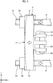
- FIG. 3 is a view when a toggle support according to the embodiment is viewed from above.
- an arrow direction indicates a direction of a force acting on the toggle support 15 when the mold is clamped.
- deformation of a toggle support body portion 151 when the mold is clamped is exaggeratedly shown by a two-dot chain line.
- the toggle support 15 includes the toggle support body portion 151 which receives a load from tie bars 16 and link pin attachment portions 153 to which link pins 20d of the toggle mechanism 20 are attached.
- the toggle support body portion 151 and the link pin attachment portions 153 are integrally formed with each other by casting or the like.
- the toggle support body portion 151 is not particularly limited, and for example, is formed in an approximately rectangular plate shape.
- a ball screw shaft insertion hole through which a ball screw shaft of the motion conversion mechanism 25 is inserted is formed at a center portion of the toggle support body portion 151.
- a load receiving portion 152 which receives a load from the tie bars 16 when the mold is clamped is formed at a corner portion of the toggle support body portion 151.
- the load receiving portions 152 are provided at four corner portions of the toggle support body portion 151.
- a through-hole into which the tie bar 16 is inserted is formed in each load receiving portion 152.
- a screw shaft 163 is formed on a rear end portion of each tie bar 16, and a screw nut 164 is screwed to the screw shaft 163.
- Each tie bar 16 is fixed to each load receiving portion 152 via the screw nut 164 or the like.
- a pair of upper and lower link pin attachment portions 153 is provided on a surface of the toggle support body portion 151 facing the movable platen 13.
- Each link pin attachment portion 153 protrudes forward from a surface of the toggle support body portion 151 facing the movable platen 13.
- the link 20c of the toggle mechanism 20 is oscillatingly attached to a tip portion of each link pin attachment portion 153 via the link pin 20d.
- an axial direction of the link pin 20d is the Y direction.
- the load receiving portions 152 are provided on both sides in the Y direction in a state where the link pin attachment portion 153 is interposed. Accordingly, as shown by an arrow in FIG. 3 , when the mold is clamped, a force by which the toggle support body portion 151 is bent in a convex shape rearward is generated. This force is released when the mold is opened.
- recessed portions 154 are provided between the link pin attachment portion 153 and the load receiving portions 152.
- Each of the recessed portions 154 forms a space for releasing the deformation of the toggle support body portion 151. Accordingly, it is possible to prevent the deformation of the toggle support body portion 151 from being transmitted to the link pin attachment portion 153, it is possible to suppress a relative minute reciprocation of the link pin 20d with respect to the link pin attachment portion 153, and it is possible to suppress wear of the link pin 20d.
- each recessed portion 154 is provided on a base portion of the link pin attachment portion 153.
- the recessed portions 154 are provided on both sides of the link pin attachment portion 153 in the Y direction.
- the recessed portion 154 may be provided on one side of the link pin attachment portion 153 in the Y direction, or the number of the recessed portions 154 may be one.
- Each of the recessed portions 154 may penetrate the base portion of the link pin attachment portion 153 in the Z direction. It is possible to further prevent the deformation of the toggle support body portion 151 from being transmitted to the link pin attachment portion 153. In addition, the recessed portion 154 may not penetrate the base portion of the link pin attachment portion 153 in the Z direction.
- the recessed portion 154 is provided on the base portion of the link pin attachment portion 153.
- an installation position thereof is not particularly limited.
- the recessed portion 154 may be provided at a boundary portion between the link pin attachment portion 153 and the toggle support body portion 151, and may be provided on a surface of the toggle support body portion 151 facing the movable platen 13.
- FIG. 4 is a view when a toggle support according to a first modification example is viewed from behind.
- a toggle support 15A includes a deformation suppression portion which suppresses deformation caused by clamping of the toggle support portion body 151, in addition to the toggle support body portion 151, the link pin attachment portions 153 (refer to FIGS. 1 to 3 ), and the recessed portion 154 (refer to FIG. 3 ).
- the deformation suppression portion includes a rib portion 157 which protrudes from the toggle support body portion 151 toward a side (for example, rear side) opposite to the link pin attachment portion 153.
- the rib portion 157 may be integrally formed with the toggle support body portion 151 by casting or the like.
- the rib portion 157 is formed on only a portion of a rib formation surface (for example, rear surface) of the toggle support body portion 151, and thus, an increase in weight of the toggle support 15A can be suppressed.
- the rib portion 157 suppress the deformation caused by the clamping of the toggle support body portion 151. Accordingly, a loss in a force caused by the deformation of the toggle support body portion 151 decreases, and thus, transmission efficiency of the mold clamping force to the mold unit 30 can be improved.
- the rib portion 157 includes an annular portion 157a which provided in a center portion of the toggle support body portion 151, a radial portion 157b which is provided from the center portion of the toggle support body portion 151 to corner portions thereof, and a linear portion 157c which is linearly formed to so as connect the corner portions of the toggle support body portion 151 to each other.
- the annular portion 157a, the radial portion 157b, and the linear portion 157c may be connected to each other.
- the radial portion 157b is provided from the center portion of the toggle support body portion 151 to the four corner portions of the toggle support body portion 151.
- the number of arms of the radial portion 157b extending from the center portion of the toggle support body portion 151 to the corner portions of the toggle support body portion 151 is not limited to four.
- the linear portion 157c is formed along an outer periphery of the toggle support body portion 151, and is linearly formed so as to connect the corner portions of the toggle support body portion 151 to each other.
- the number of the linear portions 157c is four.
- the number of the linear portions 157c is not limited to four.
- the rib portion 157 includes both the radial portion 157b and the linear portion 157c. However, the rib portion 157 may include only one. In addition, the rib portion 157 may not include the annular portion 157a.
- FIG. 5 is a view when a toggle support according to a second modification example is viewed from above.
- an arrow direction indicates a direction of a force acting on a toggle support 15B when the mold is clamped.
- deformation of the toggle support body portion 151 when the mold is clamped is exaggeratedly shown by a two-dot chain line.
- the toggle support 15B includes a resistance generating portion 158 serving as a deformation suppression portion, in addition to the toggle support body portion 151, the link pin attachment portions 153, and the recessed portions 154.
- both end portions 158a and 158b are fixed to the toggle support body portion 151, and an intermediate portion between both end portions 158a and 158b generates a resistance with respect to the deformation caused by the clamping of the toggle support body portion 151 without being fixed to the toggle support body portion 151.
- the intermediate portion is configured of a rod 158c.
- the rod 158c is fixed to both end portions 158a and 158b of the resistance generating portion 158 via nuts 158d and 158e screwed to the rod 158c.
- the rod 158c generates a resistance with respect to the deformation caused by the clamping of the toggle support body portion 151 by an elastic restoring force, and suppress the deformation caused by the clamping of the toggle support body portion 151.
- the resistance generating portion 158 is provided in only a portion of the rear surface of the toggle support body portion 151, and an increase in weight of the toggle support 15B can be suppressed. In addition, the resistance generating portion 158 suppresses the deformation caused by the clamping of the toggle support body portion 151. Accordingly, a loss in a force caused by the deformation of the toggle support body portion 151 decreases, and thus, transmission efficiency of the mold clamping force to the mold unit 30 can be improved.
- the rod 158c extends in an axial direction by the deformation caused by the clamping of the toggle support body portion 151.
- a compressive stress may be applied to the rod 158c in advance before the clamping is performed such that an excessive tensile stress is not applied to the rod 158. Accordingly, it is possible to prevent the rod 158c from being ruptured by the tensile stress .
- the compressive stress applied to the rod 158c in advance can be adjusted by fastening forces of the nuts 158d and 158e.
- the resistance generating portion 158 is linearly provided to connect the corner portions of the toggle support body portion 151 to each other along the outer periphery of the toggle support body portion 151.
- the number of the rods 158c is four.
- the number of the rods 158c is not limited to four.
- the rod 158c is linearly provided to connect the corner portions of the toggle support body portion 151 to each other.
- the rod 158c may be radially provided from the center portion of the toggle support body portion 151 to the corner portions of the toggle support body portion 151, or may be formed in both shapes .
- the annular portion 157a shown in FIG. 4 may be provided at the center portion of the toggle support body portion 151, or one end of the rod 158c may be fixed to the annular portion 157a. In this way, both the resistance generating portion 158 and the rib portion 157 shown in FIG. 4 may be used.
- a spring may be used, and the configuration of the intermediate portion is not particularly limited.
- FIG. 6 is a view when a toggle support according to a third modification example is viewed from above.
- an arrow direction indicates a direction of a force acting on a toggle support 15C when the mold is clamped.
- deformation of the toggle support body portion 151 when the mold is clamped is exaggeratedly shown by a two-dot chain line.
- the toggle support 15C includes a reinforcement portion 159 serving as a deformation suppression portion, in addition to the toggle support body portion 151, the link pin attachment portion 153, and the recessed portion 154.
- the reinforcement portion 159 is formed of a material having a young' modulus higher than that of the toggle support body portion 151.
- the reinforcement portion 159 is formed of a material different from that of the toggle support body portion 151, and thus, the reinforcement portion 159 is fixed to the toggle support body portion 151 by a bolt, welding, or the like.
- the reinforcement portion 159 suppresses the deformation caused by the clamping of the toggle support body portion 151. Accordingly, a loss in a force caused by the deformation of the toggle support body portion 151 decreases, and thus, transmission efficiency of the mold clamping force to the mold unit 30 can be improved.
- the reinforcement portion 159 is formed of a material having a young's modulus higher than that of the toggle support body portion 151, and thus, a thickness of the reinforcement portion 159 can be thinned, and thus, an increase in weight of the toggle support 15C can be suppressed.
- the reinforcement portion 159 is formed in a plate shape. However, similar to the rib portion 157, the reinforcement portion 159 may be radially provided from the center portion of the toggle support body portion 151 to the corner portions of the toggle support body portion 151, or may be linearly provided so as to connect the corner portions of the toggle support body portion 151.
- the reinforcement portion 159 may be used along with the rib portion 157 shown in FIG. 4 , or may be fixed to the rib portion 157 by a bolt, welding, or the like.
- the deformation suppression portion may be configured of a plurality of combinations of the rib portion 157, the resistance generating portion 158, and the reinforcement portion 159.
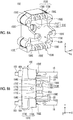
- FIGS. 7A and 7B are views showing a toggle support according to a fourth modification example.
- FIG. 7A is a perspective view showing the toggle support according to the fourth modification example.
- FIG. 7B is a view when the toggle support according to the fourth modification example is viewed from above.
- an arrow direction indicates a direction of a force acting on a toggle support 15D when the mold is clamped.
- deformation of a toggle support body portion 151D when the mold is clamped is exaggeratedly shown by a two-dot chain line.
- the toggle support 15D of the present modification example includes a toggle support body portion 151D which receives a load from the tie bars 16, link pin attachment portions 153D to which link pins 20d of the toggle mechanism 20 (refer to FIGS. 1 and 2 ) are attached, and toggle support arm portions 155D which hold front end portions of guide rods 22 guiding the crossheads 20a in the front-rear direction.
- the toggle support body portion 151D includes a plate-shaped portion 171D which is formed in an approximately rectangular shape when viewed in the X direction and a tubular portion 172D which protrudes in the X direction from an outer peripheral edge portion of the plate-shaped portion 171D.
- the plate-shaped portion 171D includes a through-hole, into which a ball screw shaft of the motion conversion mechanism 25 is inserted, at a center portion thereof.
- the tubular portion 172D is formed in a rectangular frame shape when viewed in the X direction, and a space 173D in which the crossheads 20a move is formed inside the tubular portion 172D.
- a pair of toggle support arm portions 155D is provided at an interval in the Y direction at a center portion in the Z direction of a surface (front surface) of the toggle support body portion 151D (more specifically, the tubular portion 172D) facing the movable platen 13.
- the pair of toggle support arm portion 155D protrudes in one direction (front side) in the mold opening and closing directions from the tubular portion 172D, bents inward to each other in the Y direction in the way, and holds the front end portions of the pair of the guide rods 22 by tip portions of the toggle support arm portions 155D.
- each guide rod 22 is formed in a columnar shape and extends in the X direction.
- the toggle support body portion 151D includes a load receiving portion 152D, which receives a load from the tie bar 16 when the mold is clamped, at each of four corner portions.
- Each load receiving portion 152D is formed in a tubular shape and includes a through-hole into which the tie bar 16 is inserted. The through-hole is formed to penetrate the tubular portion 172D and the plate-shaped portion 171D in the X direction.
- the load receiving portion 152D is configured by a corner portion of the tubular portion 172D and a corner portion of the plate-shaped portion 171D.
- each load receiving portion 152D may receive a load from each tie bar 16 via the screw nut 164.
- a screw shaft 163 is formed on a rear end portion of the tie bar 16, and the screw nut 164 is screwed to the screw shaft 163.
- the screw nut 164 may be attached to the load receiving portion 152D in a rotatable manner and a movable forward or rearward manner.
- the screw nuts 164 rotate, and thus, an interval L (refer to FIGS. 1 and 2 ) between the toggle support body portions 151D and the stationary platen 12 can be adjusted according to a change in a space of the mold unit 30. This adjustment may be referred to as a mold space adjustment.
- Each link pin attachment portion 153D includes attachment plates 175D which protrude in one direction (front side) in the mold opening and closing directions from the tubular portion 172D.
- a plurality of the attachment plates 175D are provided at intervals in the Y direction and are perpendicular to the Y direction.
- connection plate 176D Base portions of the attachment plates 175D are connected to each other by a connection plate 176D.
- rounded fillet portions 177D may be formed at corner portions between the attachment plates 175D and the connection plate 176D.
- each attachment plate 175D in the Y direction a through-hole which penetrates each attachment plate 175D in the Y direction is formed on a tip portion of each attachment plate 175D.
- the link pins 20d are inserted into the through-holes, and thus, the link 20c is oscillatingly attached to the link pin attachment portion 153D via the link pin 20d.
- An axial direction of the link pin 20d is the Y direction.
- a pair of link pin attachment portions 153D is provided at an interval in the Z direction at a center portion in the Y direction of a surface (front surface) of the toggle support body portion 151D (more specifically, the tubular portion 172D) facing the movable platen 13.
- the load receiving portions 152D are provided on both sides in the Y direction in a state where each link pin attachment portion 153D is interposed therebetween.
- the link pin attachment portion 153D is pressed rearward and the load receiving portion 152D is pulled forward.
- the toggle support body portion 151D is bent rearward in a convex shape. This deformation is released when the mold is opened.
- recessed portions 154D are provided between the link pin attachment portions 153D and the load receiving portions 152D.
- each recessed portion 154D is provided on a base portion of the link pin attachment portion 153D which protrudes forward from the tubular portion 172D.
- the recessed portions 154D are formed on both end surfaces of the base portion of each link pin attachment portion 153D in the Y direction. That is, in the plurality of (for example, three) attachment plates 175D which are provided at intervals in the Y direction, the recessed portions 154D are formed on outer surfaces in the Y direction of the base portions of two attachment plates 175D provided on both ends in the Y direction.
- FIGS. 10A and 10B are views showing a toggle support in the related art.
- FIG. 10A is a perspective view showing the toggle support in the related art.
- FIG. 10B is a view when the toggle support in the related art is viewed from above.
- an arrow direction indicates a direction of a force acting on a toggle support 15G when the mold is clamped.
- deformation of a toggle support body portion 151G when the mold is clamped is exaggeratedly shown by a two-dot chain line.
- fillet portions 177G are formed at corner portions between attachment plates 175G and a connection plate 176G.
- fillet portions 154G are formed on outer side surfaces in the Y direction of the base portion of the two attachment plates 175G provided on both ends in the Y direction. That is, when viewed in the Z direction, the fillet portions 154G are formed on both end surfaces of the base portion of the link pin attachment portion 153D in the Y direction.
- load receiving portions 152G are provided on both sides in the Y direction in a state where each link pin attachment portion 153G is interposed therebetween.
- the link pin attachment portion 153G is pressed rearward and the load receiving portion 152G is pulled forward.
- the toggle support body portion 151G is bent rearward in a convex shape. This deformation is released when the mold is opened.
- the toggle support 15G of the related art when viewed in the Z direction, fillet portions 154G are provided on both end surfaces of the base portion of the link pin attachment portion 153D in the Y direction. Accordingly, deformation of the toggle support body portion 151G easily spreads to the base portion of the link pin attachment portion 153G on both sides of the link pin attachment portion 153G in the Y direction. For example, according to a curvature of the toggle support body portion 151G, two attachment plates 175G on both ends in the Y direction is bent toward the attachment plate 175G side positioned at the center in the Y direction. As a result, the link pin 20d tends to make a relatively minute reciprocation with respect to the link pin attachment portion 153G, and the link pin 20d easily wears.
- the recessed portions 154D are provided on end surfaces of the base portion of each link pin attachment portion 153D in the Y direction.
- Each of the recessed portions 154D forms a space for releasing the deformation of the toggle support body portion 151D, and thus, the deformation of the toggle support body portion 151D is prevented from being transmitted to each link pin attachment portion 153D. Accordingly, it is possible to suppress the relative minute reciprocation of the link pin 20d with respect to the link pin attachment portion 153D, and it is possible to suppress wear of the link pin 20d.
- each recessed portion 154D extends from one end in the Z direction on the end surface of the base portion of the link pin attachment portion 153D in the Y direction to the other end in the Z direction. Accordingly, it is possible to further prevent the deformation of the toggle support body portion 151D from being transmitted to the link pin attachment portion 153D. As a result, it is possible to further suppress the relative minute reciprocation of the link pin 20d with respect to the link pin attachment portion 153D, and it is possible to further suppress wear of the link pin 20d.
- the recessed portion 154D may be formed on one end surface of the base portion of each link pin attachment portion 153D in the Y direction. However, as shown in FIG. 7B , the recessed portions 154D may be formed on both end surfaces of the base portion of each link pin attachment portion 153D in the Y direction. Accordingly, it is possible to further prevent the deformation of the toggle support body portion 151D from being transmitted to the link pin attachment portion 153D. As a result, it is possible to further suppress the relative minute reciprocation of the link pin 20d with respect to the link pin attachment portion 153D, and it is possible to further suppress wear of the link pin 20d.
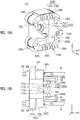
- FIGS. 8A and 8B are views showing a toggle support according to a fifth modification example.
- FIG. 8A is a perspective view showing the toggle support according to the fifth modification example.
- FIG. 8B is a view when the toggle support according to the fifth modification example is viewed from above.
- an arrow direction indicates a direction of a force acting on a toggle support 15E when the mold is clamped.
- deformation of a toggle support body portion 151E when the mold is clamped is exaggeratedly shown by a two-dot chain line.
- the toggle support 15E of the present modification example includes a toggle support body portion 151E which receives a load from the tie bars 16, link pin attachment portions 153E to which link pins 20d of the toggle mechanism 20 (refer to FIGS. 1 and 2 ) are attached, and toggle support arm portions 155E which hold front end portions of guide rods 22 guiding the crossheads 20a in the front-rear direction.
- the toggle support body portion 151E includes a plate-shaped portion 171E which is formed in an approximately rectangular shape when viewed in the X direction and a tubular portion 172E which protrudes in the X direction from an outer peripheral edge portion of the plate-shaped portion 171E.
- the plate-shaped portion 171E includes a through-hole, into which the ball screw shaft of the motion conversion mechanism 25 is inserted, at a center portion thereof.
- the tubular portion 172E is formed in a rectangular frame shape when viewed in the X direction, and a space 173D in which the crossheads 20a move is formed inside the tubular portion 17eE.
- a pair of toggle support arm portions 155E is provided at an interval in the Y direction at a center portion in the Z direction of a surface (front surface) of the toggle support body portion 151E (more specifically, the tubular portion 172E) facing the movable platen 13.
- the pair of toggle support arm portion 155E protrudes in one direction (front side) in the mold opening and closing directions from the tubular portion 172E, bents inward to each other in the Y direction in the way, and holds the front end portions of the pair of the guide rods 22 by tip portions of the toggle support arm portions 155E.
- each guide rod 22 is formed in a columnar shape and extends in the X direction.
- the toggle support body portion 151E includes a load receiving portion 152E, which receives a load from the tie bar 16 when the mold is clamped, at each of four corner portions.
- Each load receiving portion 152E is formed in a tubular shape and includes a through-hole into which the tie bar 16 is inserted. The through-hole is formed to penetrate the tubular portion 172E and the plate-shaped portion 171E in the X direction.
- the load receiving portion 152E is configured by a corner portion of the tubular portion 172E and a corner portion of the plate-shaped portion 171E.
- each load receiving portion 152E may receive a load from each tie bar 16 via the screw nut 164.
- the screw shaft 163 is formed on the rear end portion of the tie bar 16, and the screw nut 164 is screwed to the screw shaft 163.
- the screw nut 164 may be attached to the load receiving portion 152E in a rotatable manner and a movable forward or rearward manner.
- the screw nuts 164 rotate, and thus, the interval L (refer to FIGS. 1 and 2 ) between the toggle support body portions 151E and the stationary platen 12 can be adjusted according to the change in the space of the mold unit 30. This adjustment may be referred to as the mold space adjustment.
- Each link pin attachment portion 153E includes attachment plates 175E which protrude in one direction (front side) in the mold opening and closing directions from the tubular portion 172E.
- a plurality of the attachment plates 175E are provided at intervals in the Y direction and are perpendicular to the Y direction.
- connection plate 176E Base portions of the attachment plates 175E are connected to each other by a connection plate 176E.
- rounded fillet portions 177E may be formed at corner portions between the attachment plates 175E and the connection plate 176E.
- fillet portions 154E may be formed on outer surfaces in the Y direction of the base portions of the two attachment plates 175G provided on both ends in the Y direction.
- each attachment plate 175E in the Y direction a through-hole which penetrates each attachment plate 175E in the Y direction is formed on a tip portion of each attachment plate 175E.
- the link pins 20d are inserted into the through-holes, and thus, the link 20c is oscillatingly attached to the link pin attachment portion 153E via the link pin 20d.
- the axial direction of the link pin 20d is the Y direction.
- a pair of link pin attachment portions 153E is provided at an interval in the Z direction at a center portion in the Y direction of a surface (front surface) of the toggle support body portion 151E (more specifically, the tubular portion 172E) facing the movable platen 13.
- the load receiving portions 152E are provided on both sides in the Y direction in a state where each link pin attachment portion 153E is interposed therebetween.
- the link pin attachment portion 153E is pressed rearward and the load receiving portion 152E is pulled forward.
- the toggle support body portion 151E is bent rearward in a convex shape. This deformation is released when the mold is opened.
- recessed portions 156E are provided between the link pin attachment portions 153E and the load receiving portions 152E.
- each recessed portion 156E is provided the front surface of the tubular portion 172E between the link pin attachment portion 153E and the load receiving portion 152E.
- the recessed portions 156E extend in the Z direction from an outer peripheral edge of a front surface of the tubular portion 172E formed in an approximately rectangular shape when viewed in the X direction to an inner peripheral edge thereof.
- Each recessed portion 156E divides the front surface of the tubular portion 172E into the link pin attachment portion 153E side and the load receiving portion 152E side.
- the recessed portion when viewed in the Z direction, does not exist on the front surface of the tubular portion 172G between each link pin attachment portion 153G and each load receiving portion 152G, and a flat surface is formed.
- deformation of the toggle support body portion 151G easily spreads to the base portion of the link pin attachment portion 153G on both sides of the link pin attachment portion 153G in the Y direction.
- the two attachment plates 175G on both ends in the Y direction is bent toward the attachment plate 175G side positioned at the center in the Y direction.
- the link pin 20d tends to make a relatively minute reciprocation with respect to the link pin attachment portion 153G, and the link pin 20d easily wears.
- each recessed portion 156E when viewed in the Z direction, each recessed portion 156E is provided the front surface of the tubular portion 172E between the link pin attachment portion 153E and the load receiving portion 152E.
- Each of the recessed portions 156E forms a space for releasing the deformation of the toggle support body portion 151E, and thus, the deformation of the toggle support body portion 151E is prevented from being transmitted to each link pin attachment portion 153E. Accordingly, it is possible to suppress the relative minute reciprocation of the link pin 20d with respect to the link pin attachment portion 153E, and it is possible to suppress wear of the link pin 20d.
- the recessed portion 156E extends in the Z direction from the outer peripheral edge to the inner peripheral edge on the front surface of the tubular portion 172E and divides the front surface of the tubular portion 172E. Accordingly, the deformation of the toggle support body portion 151E is further prevented from being transmitted to each link pin attachment portion 153E. As a result, it is possible to further suppress the relative minute reciprocation of the link pin 20d with respect to the link pin attachment portion 153E, and it is possible to further suppress wear of the link pin 20d.
- the recessed portion 156E may be formed on one side of the link pin attachment portion 153E in the Y direction. However, as shown in FIG. 8B , the recessed portions 156E may be formed on both sides of the link pin attachment portion 153E in the Y direction. Accordingly, the deformation of the toggle support body portion 151E is further prevented from being transmitted to each link pin attachment portion 153E. As a result, it is possible to further suppress the relative minute reciprocation of the link pin 20d with respect to the link pin attachment portion 153E, and it is possible to further suppress wear of the link pin 20d.
- the recessed portion 156E of the present modification example may be used together with the recessed portion 154D of the fourth modification example. That is, in the present modification example, the fillet portions 154E are formed on both end surfaces of the base portion of the link pin attachment portion 153E in the Y direction. However, instead, the recessed portions 154D of the fourth modification example may be formed.
- FIGS. 9A and 9B are views showing a toggle support according to a sixth modification example.
- FIG. 9A is a sectional view of a toggle support according to the sixth modification example and is a sectional view taken along line A-A of FIG. 9B.
- FIG. 9B is a view when the toggle support according to the sixth modification example is viewed from above.
- an arrow direction indicates a direction of a force acting on a toggle support 15F when the mold is clamped.
- deformation of a toggle support body portion 151F when the mold is clamped is exaggeratedly shown by a two-dot chain line.
- the toggle support 15F of the present modification example includes a toggle support body portion 151F which receives a load from the tie bars 16, link pin attachment portions 153F to which link pins 20d of the toggle mechanism 20 (refer to FIGS. 1 and 2 ) are attached, and toggle support arm portions 155F which hold front end portions of guide rods 22 guiding the crossheads 20a in the front-rear direction.
- the toggle support body portion 151F includes a plate-shaped portion 171F which is formed in an approximately rectangular shape when viewed in the X direction and a tubular portion 172F which protrudes in the X direction from an outer peripheral edge portion of the plate-shaped portion 171F.
- the plate-shaped portion 171F includes a through-hole, into which a ball screw shaft of the motion conversion mechanism 25 is inserted, at a center portion thereof.
- the tubular portion 172F is formed in a rectangular frame shape when viewed in the X direction, and a space 173D in which the crossheads 20a move is formed inside the tubular portion 172D.
- a pair of toggle support arm portions 155F is provided at an interval in the Y direction at a center portion in the Z direction of a surface (front surface) of the toggle support body portion 151F (more specifically, the tubular portion 172F) facing the movable platen 13.
- the pair of toggle support arm portion 155F protrudes in one direction (front side) in the mold opening and closing directions from the tubular portion 172F, bents inward to each other in the Y direction in the way, and holds the front end portions of the pair of the guide rods 22 by tip portions of the toggle support arm portions 155F.
- each guide rod 22 is formed in a columnar shape and extends in the X direction.
- the toggle support body portion 151F includes a load receiving portion 152F, which receives a load from the tie bar 16 when the mold is clamped, at each of four corner portions.
- Each load receiving portion 152F is formed in a tubular shape and includes a through-hole into which the tie bar 16 is inserted. The through-hole is formed to penetrate the tubular portion 172F and the plate-shaped portion 171F in the X direction.
- the load receiving portion 152F is configured by a corner portion of the tubular portion 172F and a corner portion of the plate-shaped portion 171F.
- each load receiving portion 152F may receive a load from each tie bar 16 via the screw nut 164.
- the screw shaft 163 is formed on a rear end portion of the tie bar 16, and the screw nut 164 is screwed to the screw shaft 163.
- the screw nut 164 may be attached to the load receiving portion 152F in a rotatable manner and a movable forward or rearward manner.
- the screw nuts 164 rotate, and thus, the interval L (refer to FIGS. 1 and 2 ) between the toggle support body portions 151F and the stationary platen 12 can be adjusted according to a change in the space of the mold unit 30. This adjustment may be referred to as the mold space adjustment.
- Each link pin attachment portion 153F is formed to be separated from the toggle support body portion 151F and is connected to the toggle support body portion 151F via a rotary shaft 181F.
- An axial direction of the rotary shaft 181F is the Z direction.
- Each link pin attachment portion 153F is rotatable with respect to the toggle support body portion 151F which supports the rotary shaft 181F.
- Each link pin attachment portion 153F includes attachment plates 175F which protrude in one direction (front side) in the mold opening and closing directions from the tubular portion 172F.
- a plurality of the attachment plates 175F are provided at intervals in the Y direction and are perpendicular to the Y direction.
- connection plate 176F Base portions of the attachment plates 175F are connected to each other by a connection plate 176F.
- rounded fillet portions 177F may be formed at corner portions between the attachment plates 175F and the connection plate 176F.
- each attachment plate 175F in the Y direction a through-hole which penetrates each attachment plate 175F in the Y direction is formed on a tip portion of each attachment plate 175F.
- the link pins 20d are inserted into the through-holes, and thus, the link 20c is oscillatingly attached to the link pin attachment portion 153F via the link pin 20d.
- An axial direction of the link pin 20d is the Y direction.
- comb-shaped portions 178F having a comb-tooth shape in the Z direction are configured by the attachment plates 175F and the connection plates 176F.
- a rotary shaft support portion 179F protrudes from a rear surface of each comb-shaped portion 178F.
- the rotary shaft support portion 179F supports a center portion of the rotary shaft 181F in the Z direction.
- a through-hole into which the rotary shaft 181F is inserted is formed in the rotary shaft support portion 179F.
- the axial direction of the rotary shaft 181F is the Z direction.
- both end portions of the rotary shaft 181F in the Z direction are supported by the tubular portion 172F.
- the tubular portion 172F supports both end portions of the rotary shaft 181F in the Z direction, and thus, includes a fork portion 180F which is bifurcated in the Y direction when viewed in the Y direction.
- Through-holes into which the rotary shaft 181F is inserted are formed in a tip portion of the fork portion 180F.
- a pair of link pin attachment portions 153F is provided at an interval in the Z direction at a center portion in the Y direction of a surface (front surface) of the toggle support body portion 151F (more specifically, the tubular portion 172F) facing the movable platen 13.
- the load receiving portions 152F are provided on both sides in the Y direction in a state where each link pin attachment portion 153D is interposed therebetween.
- the link pin attachment portion 153D is pressed rearward and the load receiving portion 152F is pulled forward.
- the toggle support body portion 151F is bent rearward in a convex shape. This deformation is released when the mold is opened.
- recessed portions 154F are provided between the link pin attachment portions 153F and the load receiving portions 152F.
- each recessed portion 154F is provided on a base portion of the link pin attachment portion 153F which protrudes forward from the tubular portion 172F.
- a dimension of the rotary shaft support portion 179F in the Y direction is smaller than a dimension of the comb-shaped portion 178F in the Y direction, and the recessed portions 154F are formed on both end surfaces of the base portion of the link pin attachment portion 153 in the Y direction.
- Each of the recessed portions 154F forms a space for releasing the deformation of the toggle support body portion 151F, and thus, the deformation of the toggle support body portion 151F is prevented from being transmitted to each link pin attachment portion 153F. Accordingly, it is possible to suppress the relative minute reciprocation of the link pin 20d with respect to the link pin attachment portion 153F, and it is possible to suppress wear of the link pin 20d.
- Each recessed portion 154F extends from one end in the Z direction on the end surface of the base portion of the link pin attachment portion 153F in the Y direction to the other end in the Z direction. Accordingly, it is possible to further prevent the deformation of the toggle support body portion 151F from being transmitted to the link pin attachment portion 153F. As a result, it is possible to further suppress the relative minute reciprocation of the link pin 20d with respect to the link pin attachment portion 153F, and it is possible to further suppress wear of the link pin 20d.
- the recessed portion 154F may be formed on one end surface of the base portion of each link pin attachment portion 153F in the Y direction. However, as shown in FIG. 9B , the recessed portions 154D may be formed on both end surfaces of the base portion of each link pin attachment portion 153F in the Y direction. Accordingly, it is possible to further prevent the deformation of the toggle support body portion 151F from being transmitted to the link pin attachment portion 153F. As a result, it is possible to further suppress the relative minute reciprocation of the link pin 20d with respect to the link pin attachment portion 153F, and it is possible to further suppress wear of the link pin 20d.
- each link pin attachment portion 153F is rotatable about the rotary shaft 181F with respect to the toggle support body portion 151F.
- the axial direction of the rotary shaft 181F is the Z direction, and when viewed in the Z direction, a moment caused by the deformation of the toggle support body portion 151F can be prevented from being transmitted to the rotary shaft 181F.
- a recessed portion similar to the recessed portion 156E of the fifth modification example may be formed. That is, when viewed in the Z direction, the recessed portion similar to the recessed portion 156E of the fifth modification example may be formed on the front surface of the tubular portion 172F between the link pin attachment portion 153F and the load receiving portion 152F.
- a horizontal mold clamping unit in which the mold opening and closing directions are the horizontal direction is used as the mold clamping unit 10.
- the mold clamping unit 10 a vertical mold clamping unit in which the mold opening and closing directions are the up-down direction may be used.
- the vertical mold clamping unit includes a lower platen, an upper platen, a toggle support, a toggle mechanism, a tie bar, or the like. Either the lower platen or the upper platen is used as the stationary platen, and the other is used as the movable platen. A lower mold is attached to the lower platen, and an upper mold is attached to the upper platen.
- the mold unit is configured of the lower mold and the upper mold.
- the lower mold may be attached to the lower platen via a rotary table.
- the toggle support is disposed below the lower platen.
- the toggle mechanism is disposed between the toggle support and the lower platen.
- the tie bar is parallel in a vertical direction, penetrates the lower platen, and connects the upper platen and the toggle support to each other.
Landscapes
- Engineering & Computer Science (AREA)
- Mechanical Engineering (AREA)
- Manufacturing & Machinery (AREA)
- Moulds For Moulding Plastics Or The Like (AREA)
Abstract
Description
- The present invention relates to an injection molding machine.
- A mold clamping unit of an injection molding machine described in PTL 1 includes a stationary platen to which a stationary mold is attached, a movable platen to which a movable mold is attached, a toggle support which is provided on a side opposite to the stationary platen based on the movable platen, and a toggle mechanism which moves the movable platen. The movable platen includes a distortion preventing portion which prevents occurrence of distortion on a mold attachment surface at a location corresponding to each supporting point of a side edge of the movable platen between a supporting point of a toggle arm of the toggle mechanism and the mold attachment surface.
- [PTL 1] Japanese Unexamined Patent Application Publication No.
9-337309 - The toggle support includes a toggle support body portion which includes a load receiving portion receiving a load from a tie bar at a corner portion and a link pin attachment portion to which a link pin of the toggle mechanism is attached. When a mold is clamped, a force in an opposite direction acts on the toggle support body portion and a link pin attachment portion, and thus, the toggle support is deformed. This deformation is released when the mold is opened.
- Deformation of the toggle support is repeated, and thus, a phenomenon referred to as fretting occurs. The fretting is a relative minute reciprocation of the link pin with respect to the link pin attachment portion. A reciprocating direction is an axial direction of the link pin. Accordingly, the link pin may wear.
- The present invention is made in consideration of the above-described problems, and an object thereof is to provide an injection molding machine capable of suppressing wear of the link pin of the toggle mechanism.
- In order to achieve the above-described object, according to an aspect of the present invention, there is provided an injection molding machine including: a toggle support which includes a toggle support body portion including a load receiving portion, which receives a load from a tie bar, at a corner portion of the toggle support body portion, and a link pin attachment portion to which a link pin of a toggle mechanism is attached, in which when viewed in a predetermined direction, the load receiving portions are provided on both sides with the link pin attachment portion interposed therebetween and a recessed portion is provided between the link pin attachment portion and the load receiving portion.
- According to the aspect of the present invention, an injection molding machine capable of suppressing wear of a link pin of a toggle mechanism.
-
-
FIG. 1 is a view showing a state when a mold opening of an injection molding machine according to an embodiment is completed. -
FIG. 2 is a view showing a state when a mold of the injection molding machine according to the embodiment is clamped. -
FIG. 3 is a view when a toggle support according to the embodiment is viewed from above. -
FIG. 4 is a view when a toggle support according to a first modification example is viewed from behind. -
FIG. 5 is a view when a toggle support according to a second modification example is viewed from above. -
FIG. 6 is a view when a toggle support according to a third modification example is viewed from above. -
FIGS. 7A and 7B are views showing a toggle support according to a fourth modification example. -
FIGS. 8A and 8B are views showing a toggle support according to a fifth modification example. -
FIGS. 9A and 9B are views showing a toggle support according to a sixth modification example. -
FIGS. 10A and 10B are views showing a toggle support in a related art. - Hereinafter, embodiments will be described with reference to the drawings. The same or corresponding reference numerals are assigned to the same or corresponding constituent elements in each drawing, and descriptions thereof are omitted. In each drawing, an X direction, a Y direction, and a Z direction are directions perpendicular to each other. The X direction indicates mold opening and closing directions. In a case where a mold clamping unit is a horizontal type injection molding machine, the Z direction indicates an up-down direction and the X direction and the Y direction indicate a horizontal direction.
-
FIG. 1 is a view showing a state when a mold opening of an injection molding machine according to an embodiment is completed.FIG. 2 is a view showing a state when a mold of the injection molding machine according to the embodiment is clamped. As shown inFIGS. 1 and2 , the injection molding machine includes a frame Fr, amold clamping unit 10, aninjection unit 40, anejector unit 50, and acontroller 90. In the following descriptions, a movement direction (a right direction inFIGS. 1 and2 ) of amovable platen 13 when a mold is closed is referred to a front side, and a movement direction (a left direction inFIGS. 1 and2 ) of themovable platen 13 when the mold is opened is referred to a rear side. - The
mold clamping unit 10 performs opening, clamping, and opening of themold unit 30. Themold clamping unit 10 is a horizontal type mold clamping unit in which the mold opening and closing directions are the horizontal direction. Themold clamping unit 10 includes astationary platen 12, amovable platen 13, atoggle support 15, atie bar 16, atoggle mechanism 20, amold clamping motor 21, and amotion conversion mechanism 25. - The
stationary platen 12 is fixed to the frame Fr. Astationary mold 32 is attached to a surface of thestationary platen 12 facing themovable platen 13. - The
movable platen 13 is movable along a guide (for example, a guide rail) 17 placed on the frame Fr and is movable forward or rearward with respect to thestationary platen 12. Amovable mold 33 is attached to a surface of themovable platen 13 facing thestationary platen 12. - The
movable platen 13 moves forward or rearward with respect to thestationary platen 12, and thus, mold closing, mold clamping, and, mold opening are performed. Themold unit 30 is configured of thestationary mold 32 and themovable mold 33. - The
toggle support 15 is connected to thestationary platen 12 at an interval, and is placed on the frame Fr to be movable in mold opening and closing directions. In addition, thetoggle support 15 may be movable along a guide which is placed on the frame Fr. The guide of thetoggle support 15 may be also used as theguide 17 of themovable platen 13. - Moreover, in the present embodiment, the
stationary platen 12 is fixed to the frame Fr, and thetoggle support 15 is movable in the mold opening and closing directions with respect to the frame Fr. However, thetoggle support 15 may be fixed to the frame Fr, and thestationary platen 12 may be movable in the mold opening and closing directions with respect to the frame Fr. - The
stationary platen 12 and thetoggle support 15 are connected to each other at an interval by thetie bar 16. A plurality of (for example, four)tie bars 16 may be used. Thetie bars 16 are parallel in the mold opening and closing directions and extend according to a mold clamping force . A moldclamping force detector 18 is provided in at least onetie bar 16. The moldclamping force detector 18 detects strain of thetie bar 16 to detect the mold clamping force and sends a signal indicating a detection result to thecontroller 90. - In addition, the mold
clamping force detector 18 is not limited to a strain gauge type detector, and may be a piezoelectric type detector, a capacitance type detector, a hydraulic type detector, an electromagnetic type detector, or the like, and the attachment position of the mold clamping force detector is also not limited to thetie bar 16. - The
toggle mechanism 20 moves themovable platen 13 with respect to thestationary platen 12. Thetoggle mechanism 20 is disposed between themovable platen 13 and thetoggle support 15. Thetoggle mechanism 20 is configured of acrosshead 20a, a pair of link groups, or the like. Each link group includes a plurality oflinks link 20b is oscillatingly attached to themovable platen 13, and theother link 20c is oscillatingly attached to thetoggle support 15. If thecrosshead 20a moves forward or rearward, the plurality oflinks movable platen 13 moves forward or rearward with respect to thetoggle support 15. - The
mold clamping motor 21 is attached to thetoggle support 15 and operates thetoggle mechanism 20. Themold clamping motor 21 moves thecrosshead 20a forward or rearward, and thus, thelinks movable platen 13 moves forward or rearward. - The
motion conversion mechanism 25 converts a rotary motion of themold clamping motor 21 into a linear motion and transmits the linear motion to thecrosshead 20a. For example, themotion conversion mechanism 25 is configured of a ball screw mechanism or the like. - The operation of the
mold clamping unit 10 is controlled by thecontroller 90. As shown inFIG. 1 or2 , thecontroller 90 includes a Central Processing Unit (CPU) 91, astorage medium 92 such as a memory, aninput interface 93, and anoutput interface 94. Thecontroller 90 performs various controls by causing theCPU 91 to execute a program stored in thestorage medium 92. In addition, thecontroller 90 receives a signal from the outside through theinput interface 93 and transmits a signal to the outside through theoutput interface 94. Thecontroller 90 controls a mold closing process, a mold clamping process, a mold opening process, or the like. - In the mold closing process, the
mold clamping motor 21 is driven to move thecrosshead 20a forward at a set speed. Accordingly, themovable platen 13 moves forward and themovable mold 33 comes into contact with thestationary mold 32. For example, a position or speed of thecrosshead 20a is detected using anencoder 21a of themold clamping motor 21 or the like. Theencoder 21a detects the rotation of themold clamping motor 21 and sends signals indicating the detection results to thecontroller 90. - In the mold clamping process, the
mold clamping motor 21 is further driven to further move thecrosshead 20a forward to a set position, and thus, a mold clamping force is generated. When the mold is clamped, acavity space 34 is formed between themovable mold 33 and thestationary mold 32, and thecavity space 34 is filled with a liquid molding material by theinjection unit 40. A filled molding material is solidified, and thus, a molding product is obtained. A plurality ofcavity spaces 34 may be provided, and in this case, a plurality of molding products may be simultaneously obtained. - In the mold opening process, the
mold clamping motor 21 is driven to move thecrosshead 20a rearward at a set speed. Accordingly, themovable platen 13 moves rearward, and themovable mold 33 is separated from thestationary mold 32. Thereafter, theejector unit 50 causes the molding product to protrude from themovable mold 33. -
FIG. 3 is a view when a toggle support according to the embodiment is viewed from above. InFIG. 3 , an arrow direction indicates a direction of a force acting on thetoggle support 15 when the mold is clamped. In addition, inFIG. 3 , deformation of a togglesupport body portion 151 when the mold is clamped is exaggeratedly shown by a two-dot chain line. - As shown in
FIGS. 1 to 3 , thetoggle support 15 includes the togglesupport body portion 151 which receives a load from tie bars 16 and linkpin attachment portions 153 to which link pins 20d of thetoggle mechanism 20 are attached. The togglesupport body portion 151 and the linkpin attachment portions 153 are integrally formed with each other by casting or the like. - The toggle
support body portion 151 is not particularly limited, and for example, is formed in an approximately rectangular plate shape. A ball screw shaft insertion hole through which a ball screw shaft of themotion conversion mechanism 25 is inserted is formed at a center portion of the togglesupport body portion 151. In addition, aload receiving portion 152 which receives a load from the tie bars 16 when the mold is clamped is formed at a corner portion of the togglesupport body portion 151. Theload receiving portions 152 are provided at four corner portions of the togglesupport body portion 151. A through-hole into which thetie bar 16 is inserted is formed in eachload receiving portion 152. - A
screw shaft 163 is formed on a rear end portion of eachtie bar 16, and ascrew nut 164 is screwed to thescrew shaft 163. Eachtie bar 16 is fixed to eachload receiving portion 152 via thescrew nut 164 or the like. - As shown in
FIGS. 1 and2 , a pair of upper and lower linkpin attachment portions 153 is provided on a surface of the togglesupport body portion 151 facing themovable platen 13. Each linkpin attachment portion 153 protrudes forward from a surface of the togglesupport body portion 151 facing themovable platen 13. Thelink 20c of thetoggle mechanism 20 is oscillatingly attached to a tip portion of each linkpin attachment portion 153 via thelink pin 20d. As shown inFIG. 3 , an axial direction of thelink pin 20d is the Y direction. - Meanwhile, as shown in
FIG. 3 , when viewed in the Z direction, theload receiving portions 152 are provided on both sides in the Y direction in a state where the linkpin attachment portion 153 is interposed. Accordingly, as shown by an arrow inFIG. 3 , when the mold is clamped, a force by which the togglesupport body portion 151 is bent in a convex shape rearward is generated. This force is released when the mold is opened. - In the present embodiment, as shown in
FIG. 3 , when viewed in the Z direction, recessedportions 154 are provided between the linkpin attachment portion 153 and theload receiving portions 152. Each of the recessedportions 154 forms a space for releasing the deformation of the togglesupport body portion 151. Accordingly, it is possible to prevent the deformation of the togglesupport body portion 151 from being transmitted to the linkpin attachment portion 153, it is possible to suppress a relative minute reciprocation of thelink pin 20d with respect to the linkpin attachment portion 153, and it is possible to suppress wear of thelink pin 20d. - For example, as shown in
FIG. 3 , each recessedportion 154 is provided on a base portion of the linkpin attachment portion 153. The recessedportions 154 are provided on both sides of the linkpin attachment portion 153 in the Y direction. In addition, the recessedportion 154 may be provided on one side of the linkpin attachment portion 153 in the Y direction, or the number of the recessedportions 154 may be one. - Each of the recessed
portions 154 may penetrate the base portion of the linkpin attachment portion 153 in the Z direction. It is possible to further prevent the deformation of the togglesupport body portion 151 from being transmitted to the linkpin attachment portion 153. In addition, the recessedportion 154 may not penetrate the base portion of the linkpin attachment portion 153 in the Z direction. - In addition, in
FIG. 3 , the recessedportion 154 is provided on the base portion of the linkpin attachment portion 153. However, an installation position thereof is not particularly limited. The recessedportion 154 may be provided at a boundary portion between the linkpin attachment portion 153 and the togglesupport body portion 151, and may be provided on a surface of the togglesupport body portion 151 facing themovable platen 13. -
FIG. 4 is a view when a toggle support according to a first modification example is viewed from behind. Atoggle support 15A includes a deformation suppression portion which suppresses deformation caused by clamping of the togglesupport portion body 151, in addition to the togglesupport body portion 151, the link pin attachment portions 153 (refer toFIGS. 1 to 3 ), and the recessed portion 154 (refer toFIG. 3 ). - For example, the deformation suppression portion includes a
rib portion 157 which protrudes from the togglesupport body portion 151 toward a side (for example, rear side) opposite to the linkpin attachment portion 153. Therib portion 157 may be integrally formed with the togglesupport body portion 151 by casting or the like. - The
rib portion 157 is formed on only a portion of a rib formation surface (for example, rear surface) of the togglesupport body portion 151, and thus, an increase in weight of thetoggle support 15A can be suppressed. In addition, therib portion 157 suppress the deformation caused by the clamping of the togglesupport body portion 151. Accordingly, a loss in a force caused by the deformation of the togglesupport body portion 151 decreases, and thus, transmission efficiency of the mold clamping force to themold unit 30 can be improved. - For example, as shown in
FIG. 4 , therib portion 157 includes anannular portion 157a which provided in a center portion of the togglesupport body portion 151, aradial portion 157b which is provided from the center portion of the togglesupport body portion 151 to corner portions thereof, and alinear portion 157c which is linearly formed to so as connect the corner portions of the togglesupport body portion 151 to each other. Theannular portion 157a, theradial portion 157b, and thelinear portion 157c may be connected to each other. - The
radial portion 157b is provided from the center portion of the togglesupport body portion 151 to the four corner portions of the togglesupport body portion 151. In addition, the number of arms of theradial portion 157b extending from the center portion of the togglesupport body portion 151 to the corner portions of the togglesupport body portion 151 is not limited to four. - The
linear portion 157c is formed along an outer periphery of the togglesupport body portion 151, and is linearly formed so as to connect the corner portions of the togglesupport body portion 151 to each other. For example, the number of thelinear portions 157c is four. In addition, the number of thelinear portions 157c is not limited to four. - In addition, the
rib portion 157 includes both theradial portion 157b and thelinear portion 157c. However, therib portion 157 may include only one. In addition, therib portion 157 may not include theannular portion 157a. -
FIG. 5 is a view when a toggle support according to a second modification example is viewed from above. InFIG. 5 , an arrow direction indicates a direction of a force acting on atoggle support 15B when the mold is clamped. In addition, inFIG. 5 , deformation of the togglesupport body portion 151 when the mold is clamped is exaggeratedly shown by a two-dot chain line. - The
toggle support 15B includes aresistance generating portion 158 serving as a deformation suppression portion, in addition to the togglesupport body portion 151, the linkpin attachment portions 153, and the recessedportions 154. - In the
resistance generating portion 158, bothend portions support body portion 151, and an intermediate portion between bothend portions support body portion 151 without being fixed to the togglesupport body portion 151. - For example, the intermediate portion is configured of a
rod 158c. Therod 158c is fixed to bothend portions resistance generating portion 158 via nuts 158d and 158e screwed to therod 158c. Therod 158c generates a resistance with respect to the deformation caused by the clamping of the togglesupport body portion 151 by an elastic restoring force, and suppress the deformation caused by the clamping of the togglesupport body portion 151. - The
resistance generating portion 158 is provided in only a portion of the rear surface of the togglesupport body portion 151, and an increase in weight of thetoggle support 15B can be suppressed. In addition, theresistance generating portion 158 suppresses the deformation caused by the clamping of the togglesupport body portion 151. Accordingly, a loss in a force caused by the deformation of the togglesupport body portion 151 decreases, and thus, transmission efficiency of the mold clamping force to themold unit 30 can be improved. - Meanwhile, the
rod 158c extends in an axial direction by the deformation caused by the clamping of the togglesupport body portion 151. In this case, a compressive stress may be applied to therod 158c in advance before the clamping is performed such that an excessive tensile stress is not applied to therod 158. Accordingly, it is possible to prevent therod 158c from being ruptured by the tensile stress . The compressive stress applied to therod 158c in advance can be adjusted by fastening forces of the nuts 158d and 158e. - As shown in
FIG. 5 , theresistance generating portion 158 is linearly provided to connect the corner portions of the togglesupport body portion 151 to each other along the outer periphery of the togglesupport body portion 151. For example, the number of therods 158c is four. In addition, the number of therods 158c is not limited to four. - Moreover, in the present modification example, the
rod 158c is linearly provided to connect the corner portions of the togglesupport body portion 151 to each other. However, therod 158c may be radially provided from the center portion of the togglesupport body portion 151 to the corner portions of the togglesupport body portion 151, or may be formed in both shapes . - In a case where the
rod 158c is radially provided, theannular portion 157a shown inFIG. 4 may be provided at the center portion of the togglesupport body portion 151, or one end of therod 158c may be fixed to theannular portion 157a. In this way, both theresistance generating portion 158 and therib portion 157 shown inFIG. 4 may be used. - Instead of the
rod 158c, or in addition to therod 158c, a spring may be used, and the configuration of the intermediate portion is not particularly limited. -
FIG. 6 is a view when a toggle support according to a third modification example is viewed from above. InFIG. 6 , an arrow direction indicates a direction of a force acting on atoggle support 15C when the mold is clamped. In addition, inFIG. 6 , deformation of the togglesupport body portion 151 when the mold is clamped is exaggeratedly shown by a two-dot chain line. - The
toggle support 15C includes areinforcement portion 159 serving as a deformation suppression portion, in addition to the togglesupport body portion 151, the linkpin attachment portion 153, and the recessedportion 154. - The
reinforcement portion 159 is formed of a material having a young' modulus higher than that of the togglesupport body portion 151. Thereinforcement portion 159 is formed of a material different from that of the togglesupport body portion 151, and thus, thereinforcement portion 159 is fixed to the togglesupport body portion 151 by a bolt, welding, or the like. - The
reinforcement portion 159 suppresses the deformation caused by the clamping of the togglesupport body portion 151. Accordingly, a loss in a force caused by the deformation of the togglesupport body portion 151 decreases, and thus, transmission efficiency of the mold clamping force to themold unit 30 can be improved. In addition, compared to a case where thereinforcement portion 159 and the togglesupport body portion 151 are formed of the same material as each other, thereinforcement portion 159 is formed of a material having a young's modulus higher than that of the togglesupport body portion 151, and thus, a thickness of thereinforcement portion 159 can be thinned, and thus, an increase in weight of thetoggle support 15C can be suppressed. - In
FIG. 6 , thereinforcement portion 159 is formed in a plate shape. However, similar to therib portion 157, thereinforcement portion 159 may be radially provided from the center portion of the togglesupport body portion 151 to the corner portions of the togglesupport body portion 151, or may be linearly provided so as to connect the corner portions of the togglesupport body portion 151. - In addition, the
reinforcement portion 159 may be used along with therib portion 157 shown inFIG. 4 , or may be fixed to therib portion 157 by a bolt, welding, or the like. The deformation suppression portion may be configured of a plurality of combinations of therib portion 157, theresistance generating portion 158, and thereinforcement portion 159. -
FIGS. 7A and 7B are views showing a toggle support according to a fourth modification example.FIG. 7A is a perspective view showing the toggle support according to the fourth modification example.FIG. 7B is a view when the toggle support according to the fourth modification example is viewed from above. InFIG. 7B , an arrow direction indicates a direction of a force acting on atoggle support 15D when the mold is clamped. In addition, inFIG. 7B , deformation of a togglesupport body portion 151D when the mold is clamped is exaggeratedly shown by a two-dot chain line. - The
toggle support 15D of the present modification example includes a togglesupport body portion 151D which receives a load from the tie bars 16, linkpin attachment portions 153D to which link pins 20d of the toggle mechanism 20 (refer toFIGS. 1 and2 ) are attached, and togglesupport arm portions 155D which hold front end portions ofguide rods 22 guiding thecrossheads 20a in the front-rear direction. - The toggle
support body portion 151D includes a plate-shapedportion 171D which is formed in an approximately rectangular shape when viewed in the X direction and atubular portion 172D which protrudes in the X direction from an outer peripheral edge portion of the plate-shapedportion 171D. The plate-shapedportion 171D includes a through-hole, into which a ball screw shaft of themotion conversion mechanism 25 is inserted, at a center portion thereof. Thetubular portion 172D is formed in a rectangular frame shape when viewed in the X direction, and aspace 173D in which thecrossheads 20a move is formed inside thetubular portion 172D. - A pair of toggle
support arm portions 155D is provided at an interval in the Y direction at a center portion in the Z direction of a surface (front surface) of the togglesupport body portion 151D (more specifically, thetubular portion 172D) facing themovable platen 13. The pair of togglesupport arm portion 155D protrudes in one direction (front side) in the mold opening and closing directions from thetubular portion 172D, bents inward to each other in the Y direction in the way, and holds the front end portions of the pair of theguide rods 22 by tip portions of the togglesupport arm portions 155D. For example, eachguide rod 22 is formed in a columnar shape and extends in the X direction. - The toggle
support body portion 151D includes aload receiving portion 152D, which receives a load from thetie bar 16 when the mold is clamped, at each of four corner portions. Eachload receiving portion 152D is formed in a tubular shape and includes a through-hole into which thetie bar 16 is inserted. The through-hole is formed to penetrate thetubular portion 172D and the plate-shapedportion 171D in the X direction. Theload receiving portion 152D is configured by a corner portion of thetubular portion 172D and a corner portion of the plate-shapedportion 171D. - When the mold is clamped, each
load receiving portion 152D may receive a load from eachtie bar 16 via thescrew nut 164. Ascrew shaft 163 is formed on a rear end portion of thetie bar 16, and thescrew nut 164 is screwed to thescrew shaft 163. Thescrew nut 164 may be attached to theload receiving portion 152D in a rotatable manner and a movable forward or rearward manner. Thescrew nuts 164 rotate, and thus, an interval L (refer toFIGS. 1 and2 ) between the togglesupport body portions 151D and thestationary platen 12 can be adjusted according to a change in a space of themold unit 30. This adjustment may be referred to as a mold space adjustment. - Each link
pin attachment portion 153D includesattachment plates 175D which protrude in one direction (front side) in the mold opening and closing directions from thetubular portion 172D. A plurality of theattachment plates 175D are provided at intervals in the Y direction and are perpendicular to the Y direction. - Base portions of the
attachment plates 175D are connected to each other by aconnection plate 176D. When viewed in the Z direction,rounded fillet portions 177D may be formed at corner portions between theattachment plates 175D and theconnection plate 176D. - Meanwhile, a through-hole which penetrates each
attachment plate 175D in the Y direction is formed on a tip portion of eachattachment plate 175D. The link pins 20d are inserted into the through-holes, and thus, thelink 20c is oscillatingly attached to the linkpin attachment portion 153D via thelink pin 20d. An axial direction of thelink pin 20d is the Y direction. - A pair of link
pin attachment portions 153D is provided at an interval in the Z direction at a center portion in the Y direction of a surface (front surface) of the togglesupport body portion 151D (more specifically, thetubular portion 172D) facing themovable platen 13. - Meanwhile, as shown in
FIG. 7B , when viewed in the Z direction, theload receiving portions 152D are provided on both sides in the Y direction in a state where each linkpin attachment portion 153D is interposed therebetween. As shown by an arrow inFIG. 7B , when the mold is clamped, the linkpin attachment portion 153D is pressed rearward and theload receiving portion 152D is pulled forward. As a result, the togglesupport body portion 151D is bent rearward in a convex shape. This deformation is released when the mold is opened. - In the
toggle support 15D of the present modification example, when viewed in the Z direction, recessedportions 154D are provided between the linkpin attachment portions 153D and theload receiving portions 152D. For example, each recessedportion 154D is provided on a base portion of the linkpin attachment portion 153D which protrudes forward from thetubular portion 172D. - For example, the recessed
portions 154D are formed on both end surfaces of the base portion of each linkpin attachment portion 153D in the Y direction. That is, in the plurality of (for example, three)attachment plates 175D which are provided at intervals in the Y direction, the recessedportions 154D are formed on outer surfaces in the Y direction of the base portions of twoattachment plates 175D provided on both ends in the Y direction. -
FIGS. 10A and 10B are views showing a toggle support in the related art.FIG. 10A is a perspective view showing the toggle support in the related art.FIG. 10B is a view when the toggle support in the related art is viewed from above. InFIG. 10B , an arrow direction indicates a direction of a force acting on atoggle support 15G when the mold is clamped. In addition, inFIG. 10B , deformation of a togglesupport body portion 151G when the mold is clamped is exaggeratedly shown by a two-dot chain line. - In the
toggle support 15G of the related art shown inFIG. 10B , when viewed in the Z direction,fillet portions 177G are formed at corner portions betweenattachment plates 175G and aconnection plate 176G. In addition,fillet portions 154G are formed on outer side surfaces in the Y direction of the base portion of the twoattachment plates 175G provided on both ends in the Y direction. That is, when viewed in the Z direction, thefillet portions 154G are formed on both end surfaces of the base portion of the linkpin attachment portion 153D in the Y direction. - Meanwhile, as shown in
FIG. 10B , when viewed in the Z direction, load receivingportions 152G are provided on both sides in the Y direction in a state where each linkpin attachment portion 153G is interposed therebetween. As shown by an arrow inFIG. 10B , when the mold is clamped, the linkpin attachment portion 153G is pressed rearward and theload receiving portion 152G is pulled forward. As a result, the togglesupport body portion 151G is bent rearward in a convex shape. This deformation is released when the mold is opened. - In the
toggle support 15G of the related art, when viewed in the Z direction,fillet portions 154G are provided on both end surfaces of the base portion of the linkpin attachment portion 153D in the Y direction. Accordingly, deformation of the togglesupport body portion 151G easily spreads to the base portion of the linkpin attachment portion 153G on both sides of the linkpin attachment portion 153G in the Y direction. For example, according to a curvature of the togglesupport body portion 151G, twoattachment plates 175G on both ends in the Y direction is bent toward theattachment plate 175G side positioned at the center in the Y direction. As a result, thelink pin 20d tends to make a relatively minute reciprocation with respect to the linkpin attachment portion 153G, and thelink pin 20d easily wears. - Meanwhile, in the
toggle support 15D of the present modification example shown inFIGS. 7A and 7B , when viewed in the Z direction, the recessedportions 154D are provided on end surfaces of the base portion of each linkpin attachment portion 153D in the Y direction. Each of the recessedportions 154D forms a space for releasing the deformation of the togglesupport body portion 151D, and thus, the deformation of the togglesupport body portion 151D is prevented from being transmitted to each linkpin attachment portion 153D. Accordingly, it is possible to suppress the relative minute reciprocation of thelink pin 20d with respect to the linkpin attachment portion 153D, and it is possible to suppress wear of thelink pin 20d. - As shown in
FIG. 7A , each recessedportion 154D extends from one end in the Z direction on the end surface of the base portion of the linkpin attachment portion 153D in the Y direction to the other end in the Z direction. Accordingly, it is possible to further prevent the deformation of the togglesupport body portion 151D from being transmitted to the linkpin attachment portion 153D. As a result, it is possible to further suppress the relative minute reciprocation of thelink pin 20d with respect to the linkpin attachment portion 153D, and it is possible to further suppress wear of thelink pin 20d. - The recessed
portion 154D may be formed on one end surface of the base portion of each linkpin attachment portion 153D in the Y direction. However, as shown inFIG. 7B , the recessedportions 154D may be formed on both end surfaces of the base portion of each linkpin attachment portion 153D in the Y direction. Accordingly, it is possible to further prevent the deformation of the togglesupport body portion 151D from being transmitted to the linkpin attachment portion 153D. As a result, it is possible to further suppress the relative minute reciprocation of thelink pin 20d with respect to the linkpin attachment portion 153D, and it is possible to further suppress wear of thelink pin 20d. -
FIGS. 8A and 8B are views showing a toggle support according to a fifth modification example.FIG. 8A is a perspective view showing the toggle support according to the fifth modification example.FIG. 8B is a view when the toggle support according to the fifth modification example is viewed from above. InFIG. 8B , an arrow direction indicates a direction of a force acting on atoggle support 15E when the mold is clamped. In addition, inFIG. 8B , deformation of a togglesupport body portion 151E when the mold is clamped is exaggeratedly shown by a two-dot chain line. - The
toggle support 15E of the present modification example includes a togglesupport body portion 151E which receives a load from the tie bars 16, linkpin attachment portions 153E to which link pins 20d of the toggle mechanism 20 (refer toFIGS. 1 and2 ) are attached, and togglesupport arm portions 155E which hold front end portions ofguide rods 22 guiding thecrossheads 20a in the front-rear direction. - The toggle
support body portion 151E includes a plate-shapedportion 171E which is formed in an approximately rectangular shape when viewed in the X direction and atubular portion 172E which protrudes in the X direction from an outer peripheral edge portion of the plate-shapedportion 171E. The plate-shapedportion 171E includes a through-hole, into which the ball screw shaft of themotion conversion mechanism 25 is inserted, at a center portion thereof. Thetubular portion 172E is formed in a rectangular frame shape when viewed in the X direction, and aspace 173D in which thecrossheads 20a move is formed inside the tubular portion 17eE. - A pair of toggle
support arm portions 155E is provided at an interval in the Y direction at a center portion in the Z direction of a surface (front surface) of the togglesupport body portion 151E (more specifically, thetubular portion 172E) facing themovable platen 13. The pair of togglesupport arm portion 155E protrudes in one direction (front side) in the mold opening and closing directions from thetubular portion 172E, bents inward to each other in the Y direction in the way, and holds the front end portions of the pair of theguide rods 22 by tip portions of the togglesupport arm portions 155E. For example, eachguide rod 22 is formed in a columnar shape and extends in the X direction. - The toggle
support body portion 151E includes aload receiving portion 152E, which receives a load from thetie bar 16 when the mold is clamped, at each of four corner portions. Eachload receiving portion 152E is formed in a tubular shape and includes a through-hole into which thetie bar 16 is inserted. The through-hole is formed to penetrate thetubular portion 172E and the plate-shapedportion 171E in the X direction. Theload receiving portion 152E is configured by a corner portion of thetubular portion 172E and a corner portion of the plate-shapedportion 171E. - When the mold is clamped, each
load receiving portion 152E may receive a load from eachtie bar 16 via thescrew nut 164. Thescrew shaft 163 is formed on the rear end portion of thetie bar 16, and thescrew nut 164 is screwed to thescrew shaft 163. Thescrew nut 164 may be attached to theload receiving portion 152E in a rotatable manner and a movable forward or rearward manner. Thescrew nuts 164 rotate, and thus, the interval L (refer toFIGS. 1 and2 ) between the togglesupport body portions 151E and thestationary platen 12 can be adjusted according to the change in the space of themold unit 30. This adjustment may be referred to as the mold space adjustment. - Each link
pin attachment portion 153E includesattachment plates 175E which protrude in one direction (front side) in the mold opening and closing directions from thetubular portion 172E. A plurality of theattachment plates 175E are provided at intervals in the Y direction and are perpendicular to the Y direction. - Base portions of the
attachment plates 175E are connected to each other by aconnection plate 176E. When viewed in the Z direction,rounded fillet portions 177E may be formed at corner portions between theattachment plates 175E and theconnection plate 176E. In addition,fillet portions 154E may be formed on outer surfaces in the Y direction of the base portions of the twoattachment plates 175G provided on both ends in the Y direction. - Meanwhile, a through-hole which penetrates each
attachment plate 175E in the Y direction is formed on a tip portion of eachattachment plate 175E. The link pins 20d are inserted into the through-holes, and thus, thelink 20c is oscillatingly attached to the linkpin attachment portion 153E via thelink pin 20d. The axial direction of thelink pin 20d is the Y direction. - A pair of link
pin attachment portions 153E is provided at an interval in the Z direction at a center portion in the Y direction of a surface (front surface) of the togglesupport body portion 151E (more specifically, thetubular portion 172E) facing themovable platen 13. - Meanwhile, as shown in
FIG. 8B , when viewed in the Z direction, theload receiving portions 152E are provided on both sides in the Y direction in a state where each linkpin attachment portion 153E is interposed therebetween. As shown by an arrow inFIG. 8B , when the mold is clamped, the linkpin attachment portion 153E is pressed rearward and theload receiving portion 152E is pulled forward. As a result, the togglesupport body portion 151E is bent rearward in a convex shape. This deformation is released when the mold is opened. - In the
toggle support 15E of the present modification example, when viewed in the Z direction, recessedportions 156E are provided between the linkpin attachment portions 153E and theload receiving portions 152E. For example, each recessedportion 156E is provided the front surface of thetubular portion 172E between the linkpin attachment portion 153E and theload receiving portion 152E. - For example, as shown in
FIG. 8A , the recessedportions 156E extend in the Z direction from an outer peripheral edge of a front surface of thetubular portion 172E formed in an approximately rectangular shape when viewed in the X direction to an inner peripheral edge thereof. Each recessedportion 156E divides the front surface of thetubular portion 172E into the linkpin attachment portion 153E side and theload receiving portion 152E side. - Meanwhile, in the
toggle support 15G of the related art shown inFIGS. 10A and 10B , when viewed in the Z direction, the recessed portion does not exist on the front surface of thetubular portion 172G between each linkpin attachment portion 153G and eachload receiving portion 152G, and a flat surface is formed. - Accordingly, in the related art, deformation of the toggle
support body portion 151G easily spreads to the base portion of the linkpin attachment portion 153G on both sides of the linkpin attachment portion 153G in the Y direction. For example, according to the curvature of the togglesupport body portion 151G, the twoattachment plates 175G on both ends in the Y direction is bent toward theattachment plate 175G side positioned at the center in the Y direction. As a result, thelink pin 20d tends to make a relatively minute reciprocation with respect to the linkpin attachment portion 153G, and thelink pin 20d easily wears. - Meanwhile, in the
toggle support 15E of the present modification example shown inFIGS. 8A and 8B , when viewed in the Z direction, each recessedportion 156E is provided the front surface of thetubular portion 172E between the linkpin attachment portion 153E and theload receiving portion 152E. Each of the recessedportions 156E forms a space for releasing the deformation of the togglesupport body portion 151E, and thus, the deformation of the togglesupport body portion 151E is prevented from being transmitted to each linkpin attachment portion 153E. Accordingly, it is possible to suppress the relative minute reciprocation of thelink pin 20d with respect to the linkpin attachment portion 153E, and it is possible to suppress wear of thelink pin 20d. - As shown in
FIG. 8A , the recessedportion 156E extends in the Z direction from the outer peripheral edge to the inner peripheral edge on the front surface of thetubular portion 172E and divides the front surface of thetubular portion 172E. Accordingly, the deformation of the togglesupport body portion 151E is further prevented from being transmitted to each linkpin attachment portion 153E. As a result, it is possible to further suppress the relative minute reciprocation of thelink pin 20d with respect to the linkpin attachment portion 153E, and it is possible to further suppress wear of thelink pin 20d. - The recessed
portion 156E may be formed on one side of the linkpin attachment portion 153E in the Y direction. However, as shown inFIG. 8B , the recessedportions 156E may be formed on both sides of the linkpin attachment portion 153E in the Y direction. Accordingly, the deformation of the togglesupport body portion 151E is further prevented from being transmitted to each linkpin attachment portion 153E. As a result, it is possible to further suppress the relative minute reciprocation of thelink pin 20d with respect to the linkpin attachment portion 153E, and it is possible to further suppress wear of thelink pin 20d. - In addition, the recessed
portion 156E of the present modification example may be used together with the recessedportion 154D of the fourth modification example. That is, in the present modification example, thefillet portions 154E are formed on both end surfaces of the base portion of the linkpin attachment portion 153E in the Y direction. However, instead, the recessedportions 154D of the fourth modification example may be formed. -
FIGS. 9A and 9B are views showing a toggle support according to a sixth modification example.FIG. 9A is a sectional view of a toggle support according to the sixth modification example and is a sectional view taken along line A-A ofFIG. 9B. FIG. 9B is a view when the toggle support according to the sixth modification example is viewed from above. InFIG. 9B , an arrow direction indicates a direction of a force acting on atoggle support 15F when the mold is clamped. In addition, inFIG. 9B , deformation of a togglesupport body portion 151F when the mold is clamped is exaggeratedly shown by a two-dot chain line. - The
toggle support 15F of the present modification example includes a togglesupport body portion 151F which receives a load from the tie bars 16, linkpin attachment portions 153F to which link pins 20d of the toggle mechanism 20 (refer toFIGS. 1 and2 ) are attached, and togglesupport arm portions 155F which hold front end portions ofguide rods 22 guiding thecrossheads 20a in the front-rear direction. - The toggle
support body portion 151F includes a plate-shapedportion 171F which is formed in an approximately rectangular shape when viewed in the X direction and atubular portion 172F which protrudes in the X direction from an outer peripheral edge portion of the plate-shapedportion 171F. The plate-shapedportion 171F includes a through-hole, into which a ball screw shaft of themotion conversion mechanism 25 is inserted, at a center portion thereof. Thetubular portion 172F is formed in a rectangular frame shape when viewed in the X direction, and aspace 173D in which thecrossheads 20a move is formed inside thetubular portion 172D. - A pair of toggle
support arm portions 155F is provided at an interval in the Y direction at a center portion in the Z direction of a surface (front surface) of the togglesupport body portion 151F (more specifically, thetubular portion 172F) facing themovable platen 13. The pair of togglesupport arm portion 155F protrudes in one direction (front side) in the mold opening and closing directions from thetubular portion 172F, bents inward to each other in the Y direction in the way, and holds the front end portions of the pair of theguide rods 22 by tip portions of the togglesupport arm portions 155F. For example, eachguide rod 22 is formed in a columnar shape and extends in the X direction. - The toggle
support body portion 151F includes aload receiving portion 152F, which receives a load from thetie bar 16 when the mold is clamped, at each of four corner portions. Eachload receiving portion 152F is formed in a tubular shape and includes a through-hole into which thetie bar 16 is inserted. The through-hole is formed to penetrate thetubular portion 172F and the plate-shapedportion 171F in the X direction. Theload receiving portion 152F is configured by a corner portion of thetubular portion 172F and a corner portion of the plate-shapedportion 171F. - When the mold is clamped, each
load receiving portion 152F may receive a load from eachtie bar 16 via thescrew nut 164. Thescrew shaft 163 is formed on a rear end portion of thetie bar 16, and thescrew nut 164 is screwed to thescrew shaft 163. Thescrew nut 164 may be attached to theload receiving portion 152F in a rotatable manner and a movable forward or rearward manner. Thescrew nuts 164 rotate, and thus, the interval L (refer toFIGS. 1 and2 ) between the togglesupport body portions 151F and thestationary platen 12 can be adjusted according to a change in the space of themold unit 30. This adjustment may be referred to as the mold space adjustment. - Each link
pin attachment portion 153F is formed to be separated from the togglesupport body portion 151F and is connected to the togglesupport body portion 151F via arotary shaft 181F. An axial direction of therotary shaft 181F is the Z direction. Each linkpin attachment portion 153F is rotatable with respect to the togglesupport body portion 151F which supports therotary shaft 181F. - Each link
pin attachment portion 153F includesattachment plates 175F which protrude in one direction (front side) in the mold opening and closing directions from thetubular portion 172F. A plurality of theattachment plates 175F are provided at intervals in the Y direction and are perpendicular to the Y direction. - Base portions of the
attachment plates 175F are connected to each other by aconnection plate 176F. When viewed in the Z direction,rounded fillet portions 177F may be formed at corner portions between theattachment plates 175F and theconnection plate 176F. - Meanwhile, a through-hole which penetrates each
attachment plate 175F in the Y direction is formed on a tip portion of eachattachment plate 175F. The link pins 20d are inserted into the through-holes, and thus, thelink 20c is oscillatingly attached to the linkpin attachment portion 153F via thelink pin 20d. An axial direction of thelink pin 20d is the Y direction. - As shown in
FIG. 9B , comb-shapedportions 178F having a comb-tooth shape in the Z direction are configured by theattachment plates 175F and theconnection plates 176F. As shown inFIG. 9A , a rotaryshaft support portion 179F protrudes from a rear surface of each comb-shapedportion 178F. - The rotary
shaft support portion 179F supports a center portion of therotary shaft 181F in the Z direction. A through-hole into which therotary shaft 181F is inserted is formed in the rotaryshaft support portion 179F. As described above, the axial direction of therotary shaft 181F is the Z direction. - Meanwhile, both end portions of the
rotary shaft 181F in the Z direction are supported by thetubular portion 172F. As shown inFIG. 9A , thetubular portion 172F supports both end portions of therotary shaft 181F in the Z direction, and thus, includes afork portion 180F which is bifurcated in the Y direction when viewed in the Y direction. Through-holes into which therotary shaft 181F is inserted are formed in a tip portion of thefork portion 180F. - A pair of link
pin attachment portions 153F is provided at an interval in the Z direction at a center portion in the Y direction of a surface (front surface) of the togglesupport body portion 151F (more specifically, thetubular portion 172F) facing themovable platen 13. - Meanwhile, as shown in
FIG. 9B , when viewed in the Z direction, theload receiving portions 152F are provided on both sides in the Y direction in a state where each linkpin attachment portion 153D is interposed therebetween. As shown by an arrow inFIG. 9B , when the mold is clamped, the linkpin attachment portion 153D is pressed rearward and theload receiving portion 152F is pulled forward. As a result, the togglesupport body portion 151F is bent rearward in a convex shape. This deformation is released when the mold is opened. - In the
toggle support 15F of the present modification example, when viewed in the Z direction, recessedportions 154F are provided between the linkpin attachment portions 153F and theload receiving portions 152F. For example, each recessedportion 154F is provided on a base portion of the linkpin attachment portion 153F which protrudes forward from thetubular portion 172F. - For example, a dimension of the rotary
shaft support portion 179F in the Y direction is smaller than a dimension of the comb-shapedportion 178F in the Y direction, and the recessedportions 154F are formed on both end surfaces of the base portion of the linkpin attachment portion 153 in the Y direction. Each of the recessedportions 154F forms a space for releasing the deformation of the togglesupport body portion 151F, and thus, the deformation of the togglesupport body portion 151F is prevented from being transmitted to each linkpin attachment portion 153F. Accordingly, it is possible to suppress the relative minute reciprocation of thelink pin 20d with respect to the linkpin attachment portion 153F, and it is possible to suppress wear of thelink pin 20d. - Each recessed
portion 154F extends from one end in the Z direction on the end surface of the base portion of the linkpin attachment portion 153F in the Y direction to the other end in the Z direction. Accordingly, it is possible to further prevent the deformation of the togglesupport body portion 151F from being transmitted to the linkpin attachment portion 153F. As a result, it is possible to further suppress the relative minute reciprocation of thelink pin 20d with respect to the linkpin attachment portion 153F, and it is possible to further suppress wear of thelink pin 20d. - The recessed
portion 154F may be formed on one end surface of the base portion of each linkpin attachment portion 153F in the Y direction. However, as shown inFIG. 9B , the recessedportions 154D may be formed on both end surfaces of the base portion of each linkpin attachment portion 153F in the Y direction. Accordingly, it is possible to further prevent the deformation of the togglesupport body portion 151F from being transmitted to the linkpin attachment portion 153F. As a result, it is possible to further suppress the relative minute reciprocation of thelink pin 20d with respect to the linkpin attachment portion 153F, and it is possible to further suppress wear of thelink pin 20d. - In addition, in the
toggle support 15F of the present modification example, each linkpin attachment portion 153F is rotatable about therotary shaft 181F with respect to the togglesupport body portion 151F. The axial direction of therotary shaft 181F is the Z direction, and when viewed in the Z direction, a moment caused by the deformation of the togglesupport body portion 151F can be prevented from being transmitted to therotary shaft 181F. As a result, it is possible to further suppress the relative minute reciprocation of thelink pin 20d with respect to the linkpin attachment portion 153F, and it is possible to further suppress wear of thelink pin 20d. - In addition, in the
toggle support 15F of the present modification example, a recessed portion similar to the recessedportion 156E of the fifth modification example may be formed. That is, when viewed in the Z direction, the recessed portion similar to the recessedportion 156E of the fifth modification example may be formed on the front surface of thetubular portion 172F between the linkpin attachment portion 153F and theload receiving portion 152F. - Hereinbefore, the embodiments or the like of the injection molding machine are described. However, the present invention is not limited to the above-described embodiments or the like, and various modifications and improvements are possible within a scope of the gist of the present invention described in claims.
- In the above-described embodiments, a horizontal mold clamping unit in which the mold opening and closing directions are the horizontal direction is used as the
mold clamping unit 10. However, themold clamping unit 10, a vertical mold clamping unit in which the mold opening and closing directions are the up-down direction may be used. The vertical mold clamping unit includes a lower platen, an upper platen, a toggle support, a toggle mechanism, a tie bar, or the like. Either the lower platen or the upper platen is used as the stationary platen, and the other is used as the movable platen. A lower mold is attached to the lower platen, and an upper mold is attached to the upper platen. The mold unit is configured of the lower mold and the upper mold. The lower mold may be attached to the lower platen via a rotary table. The toggle support is disposed below the lower platen. The toggle mechanism is disposed between the toggle support and the lower platen. The tie bar is parallel in a vertical direction, penetrates the lower platen, and connects the upper platen and the toggle support to each other. - Priority is claimed to Japanese Patent Application No.
2016-062412, filed March 25, 2016 -
- 10:
- mold clamping unit
- 12:
- stationary platen
- 13:
- movable platen
- 15:
- toggle support
- 151:
- toggle support body portion
- 152:
- load receiving portion
- 153:
- link pin attachment portion
- 154:
- recessed portion
- 157:
- rib portion
- 158:
- resistance generating portion
- 159:
- reinforcement portion
- 16:
- tie bar
- 30:
- mold unit
- 40:
- injection unit
- 50:
- ejector unit
Claims (8)
- An injection molding machine comprising:a toggle support which includes a toggle support body portion including a load receiving portion, which receives a load from a tie bar, at a corner portion of the toggle support body portion, and a link pin attachment portion to which a link pin of a toggle mechanism is attached,wherein when viewed in a predetermined direction, the load receiving portions are provided on both sides with the link pin attachment portion interposed therebetween and a recessed portion is provided between the link pin attachment portion and the load receiving portion.
- The injection molding machine according to claim 1,
wherein the recessed portion is provided on a base portion of the link pin attachment portion which protrudes in one direction in mold opening and closing directions from the toggle support body portion, - The injection molding machine according to claim 1 or 2,
wherein the toggle support further includes a deformation suppression portion which suppresses deformation caused by clamping of the toggle support body portion. - The injection molding machine according to claim 3,
wherein the deformation suppression portion is radially provided from a center portion of the toggle support body portion to the corner portion of the toggle support body portion. - The injection molding machine according to claim 3 or 4,
wherein the deformation suppression portion is linearly provided to connect the corner portions of the toggle support body portion to each other. - The injection molding machine according to any one of claims 3 to 5,
wherein the deformation suppression portion includes a rib portion which protrudes from the toggle support body portion toward a side opposite to the link pin attachment portion. - The injection molding machine according to any one of claims 3 to 6,
wherein the deformation suppression portion includes a resistance generating portion which has both end portions fixed to the toggle support body portion and an intermediate portion, between both end portions, which is not fixed to the toggle support body portion and generates a resistance with respect to the deformation. - The injection molding machine according to any one of claims 3 to 7,
wherein the deformation suppression portion includes a reinforcement portion which is formed of a material having a young' modulus higher than that of the toggle support body portion.
Applications Claiming Priority (2)
| Application Number | Priority Date | Filing Date | Title |
|---|---|---|---|
| JP2016062412 | 2016-03-25 | ||
| PCT/JP2017/012488 WO2017164422A1 (en) | 2016-03-25 | 2017-03-27 | Injection molding machine |
Publications (3)
| Publication Number | Publication Date |
|---|---|
| EP3434441A1 true EP3434441A1 (en) | 2019-01-30 |
| EP3434441A4 EP3434441A4 (en) | 2019-08-14 |
| EP3434441B1 EP3434441B1 (en) | 2021-09-08 |
Family
ID=59900503
Family Applications (1)
| Application Number | Title | Priority Date | Filing Date |
|---|---|---|---|
| EP17770461.6A Active EP3434441B1 (en) | 2016-03-25 | 2017-03-27 | Injection molding machine |
Country Status (4)
| Country | Link |
|---|---|
| EP (1) | EP3434441B1 (en) |
| JP (1) | JP6965237B2 (en) |
| CN (1) | CN108698290A (en) |
| WO (1) | WO2017164422A1 (en) |
Families Citing this family (2)
| Publication number | Priority date | Publication date | Assignee | Title |
|---|---|---|---|---|
| WO2022210791A1 (en) * | 2021-03-31 | 2022-10-06 | 住友重機械工業株式会社 | Movable platen |
| JP7856300B2 (en) * | 2022-05-31 | 2026-05-11 | ヤマハロボティクス株式会社 | Resin encapsulation device |
Family Cites Families (13)
| Publication number | Priority date | Publication date | Assignee | Title |
|---|---|---|---|---|
| JP3418535B2 (en) | 1997-12-11 | 2003-06-23 | 住友ベークライト株式会社 | Die mechanism for extrusion molding with variable cross-sectional shape |
| JP3715246B2 (en) * | 2001-07-13 | 2005-11-09 | 住友重機械工業株式会社 | Movable mold support device for injection molding machine |
| JP3914937B2 (en) * | 2004-04-05 | 2007-05-16 | ファナック株式会社 | Molding mechanism of injection molding machine |
| AT504413B1 (en) * | 2006-09-18 | 2008-12-15 | Engel Austria Gmbh | Closing unit of an injection molding machine |
| JP5426142B2 (en) * | 2008-10-31 | 2014-02-26 | 東洋機械金属株式会社 | Molding machine |
| JP5620245B2 (en) * | 2010-12-08 | 2014-11-05 | ファナック株式会社 | Toggle mold clamping device |
| JP5059952B2 (en) * | 2011-02-14 | 2012-10-31 | ファナック株式会社 | Rear platen of toggle link type mold clamping device |
| JP5134110B2 (en) * | 2011-05-12 | 2013-01-30 | ファナック株式会社 | Toggle mold clamping device |
| JP5800881B2 (en) * | 2013-11-06 | 2015-10-28 | ファナック株式会社 | Mold mounting machine for injection molding machine |
| JP5883045B2 (en) * | 2014-02-10 | 2016-03-09 | ファナック株式会社 | Fixed platen of injection molding machine |
| JP6329517B2 (en) * | 2014-08-04 | 2018-05-23 | 日精樹脂工業株式会社 | Clamping mechanism |
| JP6338975B2 (en) * | 2014-08-28 | 2018-06-06 | 住友重機械工業株式会社 | Injection molding machine |
| JP6727838B2 (en) * | 2015-02-18 | 2020-07-22 | 芝浦機械株式会社 | Movable plate, opening/closing device, and molding device |
-
2017
- 2017-03-27 WO PCT/JP2017/012488 patent/WO2017164422A1/en not_active Ceased
- 2017-03-27 CN CN201780011310.5A patent/CN108698290A/en active Pending
- 2017-03-27 JP JP2018507469A patent/JP6965237B2/en active Active
- 2017-03-27 EP EP17770461.6A patent/EP3434441B1/en active Active
Also Published As
| Publication number | Publication date |
|---|---|
| WO2017164422A1 (en) | 2017-09-28 |
| EP3434441A4 (en) | 2019-08-14 |
| JPWO2017164422A1 (en) | 2019-02-14 |
| CN108698290A (en) | 2018-10-23 |
| EP3434441B1 (en) | 2021-09-08 |
| JP6965237B2 (en) | 2021-11-10 |
Similar Documents
| Publication | Publication Date | Title |
|---|---|---|
| EP3434441B1 (en) | Injection molding machine | |
| JP6011001B2 (en) | Material testing machine | |
| JP6383705B2 (en) | Clamping mechanism | |
| WO2016002836A1 (en) | Opening and closing device and molding device | |
| EP2641718A1 (en) | Injection molding machine with an ejector unit | |
| CN107225727B (en) | Injection molding machine | |
| US8585395B2 (en) | Toggle type mold clamping device | |
| JP6072385B1 (en) | Mold opening and closing device | |
| CN104325673B (en) | For being manufactured the forcing press of stampings by dusty material | |
| WO2011023186A3 (en) | Device for compensating acceleration forces by means of impulse coupling in measuring machines and tool machines in at least one translatory active machine axis | |
| JP6054227B2 (en) | Injection molding machine | |
| KR101739190B1 (en) | Injection molding machine | |
| US20140234472A1 (en) | Closing unit of an injection molding machine | |
| EP2993024B1 (en) | Injection molding machine | |
| EP3434438A1 (en) | Injection molding machine | |
| EP3147097B1 (en) | Injection molding machine | |
| EP3434440A1 (en) | Injection molding machine | |
| JP2008529839A (en) | Injection molding equipment for plastic processing | |
| KR102174128B1 (en) | Injection molding machine | |
| CN214036352U (en) | Hydraulic oil cylinder capable of preventing piston rod from compression deformation | |
| KR101618973B1 (en) | Injection molding machine | |
| KR20130072204A (en) | Mechanism and system for clamping | |
| EP3075513B1 (en) | Injection molding machine | |
| KR101741772B1 (en) | Device for assembling yoke and bearing and for measuring yoke of steering apparatus for vihicle | |
| US852825A (en) | Cotton-press. |
Legal Events
| Date | Code | Title | Description |
|---|---|---|---|
| STAA | Information on the status of an ep patent application or granted ep patent |
Free format text: STATUS: THE INTERNATIONAL PUBLICATION HAS BEEN MADE |
|
| PUAI | Public reference made under article 153(3) epc to a published international application that has entered the european phase |
Free format text: ORIGINAL CODE: 0009012 |
|
| STAA | Information on the status of an ep patent application or granted ep patent |
Free format text: STATUS: REQUEST FOR EXAMINATION WAS MADE |
|
| 17P | Request for examination filed |
Effective date: 20181018 |
|
| AK | Designated contracting states |
Kind code of ref document: A1 Designated state(s): AL AT BE BG CH CY CZ DE DK EE ES FI FR GB GR HR HU IE IS IT LI LT LU LV MC MK MT NL NO PL PT RO RS SE SI SK SM TR |
|
| AX | Request for extension of the european patent |
Extension state: BA ME |
|
| DAV | Request for validation of the european patent (deleted) | ||
| DAX | Request for extension of the european patent (deleted) | ||
| STAA | Information on the status of an ep patent application or granted ep patent |
Free format text: STATUS: EXAMINATION IS IN PROGRESS |
|
| A4 | Supplementary search report drawn up and despatched |
Effective date: 20190711 |
|
| RIC1 | Information provided on ipc code assigned before grant |
Ipc: B29C 45/66 20060101AFI20190705BHEP Ipc: B22D 17/26 20060101ALI20190705BHEP |
|
| 17Q | First examination report despatched |
Effective date: 20190729 |
|
| GRAP | Despatch of communication of intention to grant a patent |
Free format text: ORIGINAL CODE: EPIDOSNIGR1 |
|
| STAA | Information on the status of an ep patent application or granted ep patent |
Free format text: STATUS: GRANT OF PATENT IS INTENDED |
|
| INTG | Intention to grant announced |
Effective date: 20210507 |
|
| GRAS | Grant fee paid |
Free format text: ORIGINAL CODE: EPIDOSNIGR3 |
|
| GRAA | (expected) grant |
Free format text: ORIGINAL CODE: 0009210 |
|
| STAA | Information on the status of an ep patent application or granted ep patent |
Free format text: STATUS: THE PATENT HAS BEEN GRANTED |
|
| AK | Designated contracting states |
Kind code of ref document: B1 Designated state(s): AL AT BE BG CH CY CZ DE DK EE ES FI FR GB GR HR HU IE IS IT LI LT LU LV MC MK MT NL NO PL PT RO RS SE SI SK SM TR |
|
| REG | Reference to a national code |
Ref country code: GB Ref legal event code: FG4D |
|
| REG | Reference to a national code |
Ref country code: CH Ref legal event code: EP Ref country code: AT Ref legal event code: REF Ref document number: 1428188 Country of ref document: AT Kind code of ref document: T Effective date: 20210915 |
|
| REG | Reference to a national code |
Ref country code: DE Ref legal event code: R096 Ref document number: 602017045713 Country of ref document: DE |
|
| REG | Reference to a national code |
Ref country code: IE Ref legal event code: FG4D |
|
| REG | Reference to a national code |
Ref country code: LT Ref legal event code: MG9D |
|
| REG | Reference to a national code |
Ref country code: NL Ref legal event code: MP Effective date: 20210908 |
|
| PG25 | Lapsed in a contracting state [announced via postgrant information from national office to epo] |
Ref country code: RS Free format text: LAPSE BECAUSE OF FAILURE TO SUBMIT A TRANSLATION OF THE DESCRIPTION OR TO PAY THE FEE WITHIN THE PRESCRIBED TIME-LIMIT Effective date: 20210908 Ref country code: SE Free format text: LAPSE BECAUSE OF FAILURE TO SUBMIT A TRANSLATION OF THE DESCRIPTION OR TO PAY THE FEE WITHIN THE PRESCRIBED TIME-LIMIT Effective date: 20210908 Ref country code: HR Free format text: LAPSE BECAUSE OF FAILURE TO SUBMIT A TRANSLATION OF THE DESCRIPTION OR TO PAY THE FEE WITHIN THE PRESCRIBED TIME-LIMIT Effective date: 20210908 Ref country code: NO Free format text: LAPSE BECAUSE OF FAILURE TO SUBMIT A TRANSLATION OF THE DESCRIPTION OR TO PAY THE FEE WITHIN THE PRESCRIBED TIME-LIMIT Effective date: 20211208 Ref country code: ES Free format text: LAPSE BECAUSE OF FAILURE TO SUBMIT A TRANSLATION OF THE DESCRIPTION OR TO PAY THE FEE WITHIN THE PRESCRIBED TIME-LIMIT Effective date: 20210908 Ref country code: FI Free format text: LAPSE BECAUSE OF FAILURE TO SUBMIT A TRANSLATION OF THE DESCRIPTION OR TO PAY THE FEE WITHIN THE PRESCRIBED TIME-LIMIT Effective date: 20210908 Ref country code: BG Free format text: LAPSE BECAUSE OF FAILURE TO SUBMIT A TRANSLATION OF THE DESCRIPTION OR TO PAY THE FEE WITHIN THE PRESCRIBED TIME-LIMIT Effective date: 20211208 Ref country code: LT Free format text: LAPSE BECAUSE OF FAILURE TO SUBMIT A TRANSLATION OF THE DESCRIPTION OR TO PAY THE FEE WITHIN THE PRESCRIBED TIME-LIMIT Effective date: 20210908 |
|
| PG25 | Lapsed in a contracting state [announced via postgrant information from national office to epo] |
Ref country code: LV Free format text: LAPSE BECAUSE OF FAILURE TO SUBMIT A TRANSLATION OF THE DESCRIPTION OR TO PAY THE FEE WITHIN THE PRESCRIBED TIME-LIMIT Effective date: 20210908 Ref country code: GR Free format text: LAPSE BECAUSE OF FAILURE TO SUBMIT A TRANSLATION OF THE DESCRIPTION OR TO PAY THE FEE WITHIN THE PRESCRIBED TIME-LIMIT Effective date: 20211209 |
|
| PG25 | Lapsed in a contracting state [announced via postgrant information from national office to epo] |
Ref country code: IS Free format text: LAPSE BECAUSE OF FAILURE TO SUBMIT A TRANSLATION OF THE DESCRIPTION OR TO PAY THE FEE WITHIN THE PRESCRIBED TIME-LIMIT Effective date: 20220108 Ref country code: SM Free format text: LAPSE BECAUSE OF FAILURE TO SUBMIT A TRANSLATION OF THE DESCRIPTION OR TO PAY THE FEE WITHIN THE PRESCRIBED TIME-LIMIT Effective date: 20210908 Ref country code: SK Free format text: LAPSE BECAUSE OF FAILURE TO SUBMIT A TRANSLATION OF THE DESCRIPTION OR TO PAY THE FEE WITHIN THE PRESCRIBED TIME-LIMIT Effective date: 20210908 Ref country code: RO Free format text: LAPSE BECAUSE OF FAILURE TO SUBMIT A TRANSLATION OF THE DESCRIPTION OR TO PAY THE FEE WITHIN THE PRESCRIBED TIME-LIMIT Effective date: 20210908 Ref country code: PT Free format text: LAPSE BECAUSE OF FAILURE TO SUBMIT A TRANSLATION OF THE DESCRIPTION OR TO PAY THE FEE WITHIN THE PRESCRIBED TIME-LIMIT Effective date: 20220110 Ref country code: PL Free format text: LAPSE BECAUSE OF FAILURE TO SUBMIT A TRANSLATION OF THE DESCRIPTION OR TO PAY THE FEE WITHIN THE PRESCRIBED TIME-LIMIT Effective date: 20210908 Ref country code: NL Free format text: LAPSE BECAUSE OF FAILURE TO SUBMIT A TRANSLATION OF THE DESCRIPTION OR TO PAY THE FEE WITHIN THE PRESCRIBED TIME-LIMIT Effective date: 20210908 Ref country code: EE Free format text: LAPSE BECAUSE OF FAILURE TO SUBMIT A TRANSLATION OF THE DESCRIPTION OR TO PAY THE FEE WITHIN THE PRESCRIBED TIME-LIMIT Effective date: 20210908 Ref country code: CZ Free format text: LAPSE BECAUSE OF FAILURE TO SUBMIT A TRANSLATION OF THE DESCRIPTION OR TO PAY THE FEE WITHIN THE PRESCRIBED TIME-LIMIT Effective date: 20210908 Ref country code: AL Free format text: LAPSE BECAUSE OF FAILURE TO SUBMIT A TRANSLATION OF THE DESCRIPTION OR TO PAY THE FEE WITHIN THE PRESCRIBED TIME-LIMIT Effective date: 20210908 |
|
| REG | Reference to a national code |
Ref country code: DE Ref legal event code: R097 Ref document number: 602017045713 Country of ref document: DE |
|
| PLBE | No opposition filed within time limit |
Free format text: ORIGINAL CODE: 0009261 |
|
| STAA | Information on the status of an ep patent application or granted ep patent |
Free format text: STATUS: NO OPPOSITION FILED WITHIN TIME LIMIT |
|
| PG25 | Lapsed in a contracting state [announced via postgrant information from national office to epo] |
Ref country code: DK Free format text: LAPSE BECAUSE OF FAILURE TO SUBMIT A TRANSLATION OF THE DESCRIPTION OR TO PAY THE FEE WITHIN THE PRESCRIBED TIME-LIMIT Effective date: 20210908 |
|
| 26N | No opposition filed |
Effective date: 20220609 |
|
| PG25 | Lapsed in a contracting state [announced via postgrant information from national office to epo] |
Ref country code: SI Free format text: LAPSE BECAUSE OF FAILURE TO SUBMIT A TRANSLATION OF THE DESCRIPTION OR TO PAY THE FEE WITHIN THE PRESCRIBED TIME-LIMIT Effective date: 20210908 |
|
| PG25 | Lapsed in a contracting state [announced via postgrant information from national office to epo] |
Ref country code: MC Free format text: LAPSE BECAUSE OF FAILURE TO SUBMIT A TRANSLATION OF THE DESCRIPTION OR TO PAY THE FEE WITHIN THE PRESCRIBED TIME-LIMIT Effective date: 20210908 |
|
| REG | Reference to a national code |
Ref country code: CH Ref legal event code: PL |
|
| GBPC | Gb: european patent ceased through non-payment of renewal fee |
Effective date: 20220327 |
|
| REG | Reference to a national code |
Ref country code: BE Ref legal event code: MM Effective date: 20220331 |
|
| PG25 | Lapsed in a contracting state [announced via postgrant information from national office to epo] |
Ref country code: LU Free format text: LAPSE BECAUSE OF NON-PAYMENT OF DUE FEES Effective date: 20220327 Ref country code: LI Free format text: LAPSE BECAUSE OF NON-PAYMENT OF DUE FEES Effective date: 20220331 Ref country code: IT Free format text: LAPSE BECAUSE OF FAILURE TO SUBMIT A TRANSLATION OF THE DESCRIPTION OR TO PAY THE FEE WITHIN THE PRESCRIBED TIME-LIMIT Effective date: 20210908 Ref country code: IE Free format text: LAPSE BECAUSE OF NON-PAYMENT OF DUE FEES Effective date: 20220327 Ref country code: GB Free format text: LAPSE BECAUSE OF NON-PAYMENT OF DUE FEES Effective date: 20220327 Ref country code: FR Free format text: LAPSE BECAUSE OF NON-PAYMENT OF DUE FEES Effective date: 20220331 Ref country code: CH Free format text: LAPSE BECAUSE OF NON-PAYMENT OF DUE FEES Effective date: 20220331 |
|
| PG25 | Lapsed in a contracting state [announced via postgrant information from national office to epo] |
Ref country code: BE Free format text: LAPSE BECAUSE OF NON-PAYMENT OF DUE FEES Effective date: 20220331 |
|
| REG | Reference to a national code |
Ref country code: AT Ref legal event code: UEP Ref document number: 1428188 Country of ref document: AT Kind code of ref document: T Effective date: 20210908 |
|
| PG25 | Lapsed in a contracting state [announced via postgrant information from national office to epo] |
Ref country code: HU Free format text: LAPSE BECAUSE OF FAILURE TO SUBMIT A TRANSLATION OF THE DESCRIPTION OR TO PAY THE FEE WITHIN THE PRESCRIBED TIME-LIMIT; INVALID AB INITIO Effective date: 20170327 |
|
| PG25 | Lapsed in a contracting state [announced via postgrant information from national office to epo] |
Ref country code: MK Free format text: LAPSE BECAUSE OF FAILURE TO SUBMIT A TRANSLATION OF THE DESCRIPTION OR TO PAY THE FEE WITHIN THE PRESCRIBED TIME-LIMIT Effective date: 20210908 Ref country code: CY Free format text: LAPSE BECAUSE OF FAILURE TO SUBMIT A TRANSLATION OF THE DESCRIPTION OR TO PAY THE FEE WITHIN THE PRESCRIBED TIME-LIMIT Effective date: 20210908 |
|
| PG25 | Lapsed in a contracting state [announced via postgrant information from national office to epo] |
Ref country code: MT Free format text: LAPSE BECAUSE OF FAILURE TO SUBMIT A TRANSLATION OF THE DESCRIPTION OR TO PAY THE FEE WITHIN THE PRESCRIBED TIME-LIMIT Effective date: 20210908 |
|
| PG25 | Lapsed in a contracting state [announced via postgrant information from national office to epo] |
Ref country code: TR Free format text: LAPSE BECAUSE OF FAILURE TO SUBMIT A TRANSLATION OF THE DESCRIPTION OR TO PAY THE FEE WITHIN THE PRESCRIBED TIME-LIMIT Effective date: 20210908 |
|
| PGFP | Annual fee paid to national office [announced via postgrant information from national office to epo] |
Ref country code: DE Payment date: 20260128 Year of fee payment: 10 |
|
| PGFP | Annual fee paid to national office [announced via postgrant information from national office to epo] |
Ref country code: AT Payment date: 20260225 Year of fee payment: 10 |