EP3434436B1 - Device and method for producing a curved fibre preform from a bi- or multidirectional fibre semi-finished product - Google Patents
Device and method for producing a curved fibre preform from a bi- or multidirectional fibre semi-finished product Download PDFInfo
- Publication number
- EP3434436B1 EP3434436B1 EP18180081.4A EP18180081A EP3434436B1 EP 3434436 B1 EP3434436 B1 EP 3434436B1 EP 18180081 A EP18180081 A EP 18180081A EP 3434436 B1 EP3434436 B1 EP 3434436B1
- Authority
- EP
- European Patent Office
- Prior art keywords
- grid
- finished product
- fibre
- lamellae
- semi
- Prior art date
- Legal status (The legal status is an assumption and is not a legal conclusion. Google has not performed a legal analysis and makes no representation as to the accuracy of the status listed.)
- Active
Links
Images


Classifications
-
- B—PERFORMING OPERATIONS; TRANSPORTING
- B29—WORKING OF PLASTICS; WORKING OF SUBSTANCES IN A PLASTIC STATE IN GENERAL
- B29C—SHAPING OR JOINING OF PLASTICS; SHAPING OF MATERIAL IN A PLASTIC STATE, NOT OTHERWISE PROVIDED FOR; AFTER-TREATMENT OF THE SHAPED PRODUCTS, e.g. REPAIRING
- B29C70/00—Shaping composites, i.e. plastics material comprising reinforcements, fillers or preformed parts, e.g. inserts
- B29C70/68—Shaping composites, i.e. plastics material comprising reinforcements, fillers or preformed parts, e.g. inserts by incorporating or moulding on preformed parts, e.g. inserts or layers, e.g. foam blocks
- B29C70/681—Component parts, details or accessories; Auxiliary operations
- B29C70/682—Preformed parts characterised by their structure, e.g. form
-
- B—PERFORMING OPERATIONS; TRANSPORTING
- B29—WORKING OF PLASTICS; WORKING OF SUBSTANCES IN A PLASTIC STATE IN GENERAL
- B29B—PREPARATION OR PRETREATMENT OF THE MATERIAL TO BE SHAPED; MAKING GRANULES OR PREFORMS; RECOVERY OF PLASTICS OR OTHER CONSTITUENTS OF WASTE MATERIAL CONTAINING PLASTICS
- B29B11/00—Making preforms
- B29B11/14—Making preforms characterised by structure or composition
- B29B11/16—Making preforms characterised by structure or composition comprising fillers or reinforcement
-
- B—PERFORMING OPERATIONS; TRANSPORTING
- B29—WORKING OF PLASTICS; WORKING OF SUBSTANCES IN A PLASTIC STATE IN GENERAL
- B29C—SHAPING OR JOINING OF PLASTICS; SHAPING OF MATERIAL IN A PLASTIC STATE, NOT OTHERWISE PROVIDED FOR; AFTER-TREATMENT OF THE SHAPED PRODUCTS, e.g. REPAIRING
- B29C53/00—Shaping by bending, folding, twisting, straightening or flattening; Apparatus therefor
- B29C53/02—Bending or folding
- B29C53/04—Bending or folding of plates or sheets
-
- B—PERFORMING OPERATIONS; TRANSPORTING
- B29—WORKING OF PLASTICS; WORKING OF SUBSTANCES IN A PLASTIC STATE IN GENERAL
- B29C—SHAPING OR JOINING OF PLASTICS; SHAPING OF MATERIAL IN A PLASTIC STATE, NOT OTHERWISE PROVIDED FOR; AFTER-TREATMENT OF THE SHAPED PRODUCTS, e.g. REPAIRING
- B29C53/00—Shaping by bending, folding, twisting, straightening or flattening; Apparatus therefor
- B29C53/02—Bending or folding
- B29C53/04—Bending or folding of plates or sheets
- B29C53/06—Forming folding lines by pressing or scoring
-
- B—PERFORMING OPERATIONS; TRANSPORTING
- B29—WORKING OF PLASTICS; WORKING OF SUBSTANCES IN A PLASTIC STATE IN GENERAL
- B29C—SHAPING OR JOINING OF PLASTICS; SHAPING OF MATERIAL IN A PLASTIC STATE, NOT OTHERWISE PROVIDED FOR; AFTER-TREATMENT OF THE SHAPED PRODUCTS, e.g. REPAIRING
- B29C66/00—General aspects of processes or apparatus for joining preformed parts
- B29C66/01—General aspects dealing with the joint area or with the area to be joined
- B29C66/05—Particular design of joint configurations
- B29C66/10—Particular design of joint configurations particular design of the joint cross-sections
- B29C66/11—Joint cross-sections comprising a single joint-segment, i.e. one of the parts to be joined comprising a single joint-segment in the joint cross-section
- B29C66/112—Single lapped joints
- B29C66/1122—Single lap to lap joints, i.e. overlap joints
-
- B—PERFORMING OPERATIONS; TRANSPORTING
- B29—WORKING OF PLASTICS; WORKING OF SUBSTANCES IN A PLASTIC STATE IN GENERAL
- B29C—SHAPING OR JOINING OF PLASTICS; SHAPING OF MATERIAL IN A PLASTIC STATE, NOT OTHERWISE PROVIDED FOR; AFTER-TREATMENT OF THE SHAPED PRODUCTS, e.g. REPAIRING
- B29C70/00—Shaping composites, i.e. plastics material comprising reinforcements, fillers or preformed parts, e.g. inserts
- B29C70/04—Shaping composites, i.e. plastics material comprising reinforcements, fillers or preformed parts, e.g. inserts comprising reinforcements only, e.g. self-reinforcing plastics
- B29C70/28—Shaping operations therefor
- B29C70/54—Component parts, details or accessories; Auxiliary operations, e.g. feeding or storage of prepregs or SMC after impregnation or during ageing
- B29C70/545—Perforating, cutting or machining during or after moulding
-
- B—PERFORMING OPERATIONS; TRANSPORTING
- B29—WORKING OF PLASTICS; WORKING OF SUBSTANCES IN A PLASTIC STATE IN GENERAL
- B29C—SHAPING OR JOINING OF PLASTICS; SHAPING OF MATERIAL IN A PLASTIC STATE, NOT OTHERWISE PROVIDED FOR; AFTER-TREATMENT OF THE SHAPED PRODUCTS, e.g. REPAIRING
- B29C70/00—Shaping composites, i.e. plastics material comprising reinforcements, fillers or preformed parts, e.g. inserts
- B29C70/04—Shaping composites, i.e. plastics material comprising reinforcements, fillers or preformed parts, e.g. inserts comprising reinforcements only, e.g. self-reinforcing plastics
- B29C70/28—Shaping operations therefor
- B29C70/54—Component parts, details or accessories; Auxiliary operations, e.g. feeding or storage of prepregs or SMC after impregnation or during ageing
- B29C70/56—Tensioning reinforcements before or during shaping
-
- B—PERFORMING OPERATIONS; TRANSPORTING
- B29—WORKING OF PLASTICS; WORKING OF SUBSTANCES IN A PLASTIC STATE IN GENERAL
- B29C—SHAPING OR JOINING OF PLASTICS; SHAPING OF MATERIAL IN A PLASTIC STATE, NOT OTHERWISE PROVIDED FOR; AFTER-TREATMENT OF THE SHAPED PRODUCTS, e.g. REPAIRING
- B29C70/00—Shaping composites, i.e. plastics material comprising reinforcements, fillers or preformed parts, e.g. inserts
- B29C70/68—Shaping composites, i.e. plastics material comprising reinforcements, fillers or preformed parts, e.g. inserts by incorporating or moulding on preformed parts, e.g. inserts or layers, e.g. foam blocks
- B29C70/74—Moulding material on a relatively small portion of the preformed part, e.g. outsert moulding
- B29C70/742—Forming a hollow body around the preformed part
-
- B—PERFORMING OPERATIONS; TRANSPORTING
- B29—WORKING OF PLASTICS; WORKING OF SUBSTANCES IN A PLASTIC STATE IN GENERAL
- B29K—INDEXING SCHEME ASSOCIATED WITH SUBCLASSES B29B, B29C OR B29D, RELATING TO MOULDING MATERIALS OR TO MATERIALS FOR MOULDS, REINFORCEMENTS, FILLERS OR PREFORMED PARTS, e.g. INSERTS
- B29K2101/00—Use of unspecified macromolecular compounds as moulding material
- B29K2101/12—Thermoplastic materials
-
- B—PERFORMING OPERATIONS; TRANSPORTING
- B29—WORKING OF PLASTICS; WORKING OF SUBSTANCES IN A PLASTIC STATE IN GENERAL
- B29K—INDEXING SCHEME ASSOCIATED WITH SUBCLASSES B29B, B29C OR B29D, RELATING TO MOULDING MATERIALS OR TO MATERIALS FOR MOULDS, REINFORCEMENTS, FILLERS OR PREFORMED PARTS, e.g. INSERTS
- B29K2105/00—Condition, form or state of moulded material or of the material to be shaped
- B29K2105/06—Condition, form or state of moulded material or of the material to be shaped containing reinforcements, fillers or inserts
- B29K2105/08—Condition, form or state of moulded material or of the material to be shaped containing reinforcements, fillers or inserts of continuous length, e.g. cords, rovings, mats, fabrics, strands or yarns
- B29K2105/0872—Prepregs
- B29K2105/0881—Prepregs unidirectional
-
- B—PERFORMING OPERATIONS; TRANSPORTING
- B29—WORKING OF PLASTICS; WORKING OF SUBSTANCES IN A PLASTIC STATE IN GENERAL
- B29K—INDEXING SCHEME ASSOCIATED WITH SUBCLASSES B29B, B29C OR B29D, RELATING TO MOULDING MATERIALS OR TO MATERIALS FOR MOULDS, REINFORCEMENTS, FILLERS OR PREFORMED PARTS, e.g. INSERTS
- B29K2307/00—Use of elements other than metals as reinforcement
- B29K2307/04—Carbon
-
- B—PERFORMING OPERATIONS; TRANSPORTING
- B29—WORKING OF PLASTICS; WORKING OF SUBSTANCES IN A PLASTIC STATE IN GENERAL
- B29L—INDEXING SCHEME ASSOCIATED WITH SUBCLASS B29C, RELATING TO PARTICULAR ARTICLES
- B29L2031/00—Other particular articles
- B29L2031/30—Vehicles, e.g. ships or aircraft, or body parts thereof
- B29L2031/3076—Aircrafts
- B29L2031/3082—Fuselages
-
- B—PERFORMING OPERATIONS; TRANSPORTING
- B29—WORKING OF PLASTICS; WORKING OF SUBSTANCES IN A PLASTIC STATE IN GENERAL
- B29L—INDEXING SCHEME ASSOCIATED WITH SUBCLASS B29C, RELATING TO PARTICULAR ARTICLES
- B29L2031/00—Other particular articles
- B29L2031/772—Articles characterised by their shape and not otherwise provided for
- B29L2031/7739—Curved shaped
-
- Y—GENERAL TAGGING OF NEW TECHNOLOGICAL DEVELOPMENTS; GENERAL TAGGING OF CROSS-SECTIONAL TECHNOLOGIES SPANNING OVER SEVERAL SECTIONS OF THE IPC; TECHNICAL SUBJECTS COVERED BY FORMER USPC CROSS-REFERENCE ART COLLECTIONS [XRACs] AND DIGESTS
- Y02—TECHNOLOGIES OR APPLICATIONS FOR MITIGATION OR ADAPTATION AGAINST CLIMATE CHANGE
- Y02T—CLIMATE CHANGE MITIGATION TECHNOLOGIES RELATED TO TRANSPORTATION
- Y02T50/00—Aeronautics or air transport
- Y02T50/40—Weight reduction
Definitions
- the present invention relates to a device for producing a curved fibre preform from a bi- or multidirectional fibre semi-finished product and to a corresponding method for producing a curved fibre preform from a bi- or multidirectional fibre semi-finished product.
- fibre preforms also generally referred to as preforms
- preforms for former structures of an aircraft or spacecraft
- it is not limited thereto but rather is transferrable to various curved fibre preforms, in particular for fuselage components of an aircraft or spacecraft.
- textile blanks of a bi- or multidirectional fibre semi-finished product are draped onto the desired former shape.
- the draping is currently usually carried out by hand.
- a necessary step in this context is the production of the former-specific curvature so as to obtain a curved fibre preform.
- shearing and/or deformation of the fibre semi-finished product are generally required.
- adaptation to the precise shape of each individual component to be produced is also carried out, in particular subsequently.
- the object of the present invention is to provide an improved device for manufacturing a curved fibre preform from a bi- or multidirectional fibre semi-finished product which makes simplified and in particular automatable manufacture possible.
- this object is achieved by a device for producing a curved fibre preform from a bi- or multidirectional fibre semi-finished product, in particular for a fuselage component of an aircraft or spacecraft, having the features of claim 1, and/or by a method for producing a curved fibre preform, in particular by means of a device according to the invention, having the features of claim 12.
- a device for producing a curved fibre preform from a bi- or multidirectional fibre semi-finished product comprising a plurality of first lamellae and a plurality of second lamellae which are formed to be couplable to one another, in particular pluggable into one another, criss-cross in such a way that they are positioned on a shared plane and thus form a grid, the lamellae at least in part being formed resiliently bendable about an axis intersecting the shared plane in such a way that a local orientation of the lamellae in the grid changes, in particular continuously; and an adhesion means which is formed for temporarily adhering the fibre semi-finished product to the grid and is configured in such a way that the local fibre orientation of the fibre semi-finished product also changes accordingly when the lamellae bend.
- a method for producing a curved fibre preform comprising the following method steps: applying a bi- or multi-directional fibre semi-finished product to a grid of a plurality of first lamellae and a plurality of second lamellae, which are coupled to one another, in particular plugged into one another, criss-cross and positioned on a shared plane, temporarily adhering the fibre semi-finished product to the grid; and resiliently bending the lamellae at least in part about an axis intersecting the shared plane, a local orientation of the lamellae in the grid changing, in particular continuously, and a local fibre orientation of the fibre semi-finished product also changing accordingly when the lamellae bend.
- the idea behind the present invention is to provide a deformation of a grid serving as a carrier structure for the fibre semi-finished product in a manner corresponding to the desired deformation of the fibre semi-finished product.
- the lamellae of the grid are formed and orientated as exactly as possible in accordance with the orientation of the fibres contained in the fibre semi-finished product, in such a way that a shared orientation of the lamellae and fibres, which can be deformed jointly, is provided.
- the lamellae and fibres thus deform in the same manner during the bending.
- a curved fibre orientation of the curved fibre preform is very precisely adjustable or controllable, in such a way that the quality of the fibre preform and thus also of the fuselage component to be produced is improved, in particular in terms of mechanical properties.
- the deformation of a silicone core used in previous devices is further avoided, the deformation of said core not geometrically corresponding to a shear deformation of a fibre semi-finished product.
- the shaping principle according to the invention makes greatly simplified automation of the process possible, as well as greatly improved reproducibility of the shaping. In this way, reduction in staffing costs and acceleration of the production process can be achieved.
- curved fibre preforms for C profiles or Z profiles of formers can be produced.
- portions of a former for example portions of a former curved through 90°, can be produced in an automated manner and with greater reproducibility using fibre preforms correspondingly curved through 90°. Subsequently, they can also be shaped into the desired profile, for example a C profile or Z profile.
- the lamellae being on a shared plane should be understood to mean that they provide a shared grid face when coupled, in particular plugged into one another. This may also merely be a shared local plane, in such a way that arched shared grid surfaces, for example for manufacturing multiple curved components, are also conceivable.
- the surface of the grid may therefore also imitate a three-dimensionally curved surface.
- the lamellae may be formed at different heights in different regions of the grid, and thus be provided adapted to a desired component shape.
- thin lamellae in particular in the form of rods, would also be conceivable at least in portions, in such a way that they can bend in not just one but a plurality of directions. In this way, three-dimensional bendings are also possible. Accordingly, the grid can also be shaped to a three-dimensional shape and/or itself deform three-dimensionally as a result of bending of the lamellae.
- Bending at least in part about an axis intersecting the shared plane should thus be understood to mean that the bending axis may be orientated perpendicular to the grid or else at an angle to portions of the grid or to the entire grid.
- the point of intersection between the axis and the shared plane need not and indeed generally will not lie within the grid, but rather in an imaginary continuation of the grid in the plane thereof.
- a grid would also be conceivable which comprises lamellae consisting of a plurality of short lamellar pieces which are connected using rotary joints.
- the individual lamellar pieces would therefore remain straight in spite of the bending of the lamellae as a whole, and the deformation would be implemented at the rotary joints.
- Adhesion of the fibre semi-finished product to the grid should be understood to mean that there is static friction between the fibre semi-finished product and the grid. This may, but need not necessarily, act directly between the grid and the fibre semi-finished product, and instead may optionally also be transmitted via an intermediate layer, for example a membrane arranged in between.
- an additional advantage of the present invention is the particularly simple possibility of automation of shaping steps for curved fibre preforms which were previously usually carried out manually.
- an adhesion means should be understood to mean an individual device or measure or a combination thereof which leads to adhesion of the semi-finished product to a surface of the grid which is sufficient for the desired deformation during bending of the lamellae.
- the adhesion means may be formed as a bonding means of the grid itself or as a soluble adhesion promoter applied thereto.
- sticky, rough, jagged and/or needle portions may be provided in an application region, provided on the grid, which is non-critical for the fibre semi-finished product, for example at an edge of the fibre semi-finished product.
- an adhesion means may contain means or measures provided externally to the grid, for example on the basis of underpressure for sucking the fibre semi-finished product on or of mechanical pressure for pressing the fibre semi-finished product on.
- the fibre semi-finished product is applied to or orientated on the grid in such a way that the fibres at least in part extend parallel to the lamellae.
- ⁇ 45° fibres of a fibre roving are orientated along the ⁇ 45° lamellae of the grid.
- the fibre semi-finished product to be deformed for producing the curved fibre preform is in particular formed as a ⁇ 45° biaxial roving or as a ⁇ 45°, 90° triaxial roving.
- the lamellae of the grid preferably also extend at ⁇ 45° angles.
- the fibre semi-finished product does not contain any 0° fibres, which would prevent stretching or compression of the roving.
- the lamellae deform in a manner corresponding to a desired progression of the fibres in the curved state.
- the fibres of the fibre semi-finished product or fibre roving therefore deform in a desired manner during the deformation of the cells of the grid, in such a way that the fibre direction is ideally locally reorientated in a manner corresponding to the deformation.
- the 90° fibres would for example also be displaced radially in a manner corresponding to the deformation.
- the 90° fibre layers would thus slide with respect to the ⁇ 45°.
- the orientation of the grid would thus correspond to the orientation of the ⁇ 45° layers, the orientation of the 90° layer not being imitated by the grid.
- the lamellae preferably also extend at 0° and 90° angles.
- the 90° lamellae and fibres in particular exclusively, would fan out radially during the bending of the lamellae, and the 0° fibres would merely be radially displaced.
- a suitable orientation of the lamellae in the grid is thus dependent in particular on the fibre orientation of the fibre semi-finished product to be shaped, and is preferably unidirectional for this purpose.
- multidimensional rovings having fibre directions and any further fibre directions would also be conceivable, as long as the fibre layers which are not orientated parallel to the grid bars are applied in the textile in such a way that they can slide relative to the other layers during deformation/shearing (for example by way of an active pattern having relatively slack thread tension in a multiaxial roving), in such a way that none of the fibre directions directly obstructs the deformation.
- a 0° fibre direction in a ⁇ 45° grid would obstruct deformation if it were knitted onto the remaining ⁇ 45° layers in such a way that it could not slide.
- the fibre preform can be processed further to form the desired component, for example by cutting off edge regions of the fibre preform and/or by further deformation to form the subsequent component shape, for example collaring the flange of a C profile for producing a former portion and/or connection to further, already deposited component layers and/or curing a binder.
- the first and second lamellae may comprise corresponding plug sockets which can be plugged into one another.
- the plug sockets combine to form a depth corresponding to a thickness of the first and/or second lamellae.
- the plug sockets are formed as slits.
- the slits extend from a longitudinal face in each case approximately as far as the centre of a lamella.
- a detensioning hole may be provided at the base of a slit to prevent grooving effects which occur during bending.
- a neutral lamella is introduced into the grid, and is arranged in the region of a theoretical or actual neutral fibre of the curved fibre preform to be produced.
- this is an irregular lamella, i.e. one arranged so as to interrupt the regular arrangement of the lamellae in the grid.
- this neutral lamella extends at a 0° orientation, in other words in the peripheral direction when the lamellae are bent.
- the neutral lamella is formed in such a way that cells of the grid which are positioned on a first side of the neutral lamella are stretched, in particular in relation to a reference direction, during bending, and cells of the grid which are positioned on a second side of the neutral lamella are compressed, in particular in relation to an identical reference direction, during bending.
- cells positioned directly on the neutral lamella are only insignificantly deformed in accordance with the bending.
- the shaping can thus be provided in a predefined manner.
- the stretching and compression are preferably each to be understood in the peripheral direction. Accordingly, the side lengths of the individual cells remain constant. Since the plug connections are formed stationary with respect to the lamellae, a stretched cell is therefore stretched in the peripheral direction and compressed in the radial direction, whilst a compressed cell is compressed in the peripheral direction and stretched in the radial direction. When the cells shear, they are therefore always stretched in one direction and shortened in another direction perpendicular thereto. The peripheral direction therefore forms the reference direction in this case.
- a stationary positioning of the plug connections with respect to the lamellae is advantageous since the fibres of the unshaped textile semi-finished product itself are thus not compressed or stretched but merely reorientated or bent and sheared with respect to one another.
- the neutral lamella may likewise be provided with plug sockets. Accordingly, in regions in which the neutral lamella is to be inserted, the lamellae of the grid are likewise formed with additional plug sockets for receiving the neutral lamella.
- a deformable membrane provided as a support face for the fibre semi-finished product is provided on the grid.
- the membrane may also be formed as a membrane which is resiliently biased to compensate the bending of the lamellae.
- it may contain an elastomer for this purpose.
- this may for example be a resilient perforated or slitted (rubber or elastomer) membrane.
- the membrane may be biased, preferably counter to the desired bending direction.
- the membrane may be biased on the side of the neutral fibre which experiences compression in the peripheral direction during the bending process, in such a way that after the bending process is carried out it is actually detensioned or still slightly biased. In this way, the deformation of the membrane occurring when the lamellae are bent is compensated, in such a way that no corrugations or folds are raised and swelling into the cavity of the cells of the grid is also prevented.
- the adhesion means comprises an underpressure box which fluidically contacts the grid.
- the underpressure box is formed in such a way that an underpressure can thus be applied in each cell of the grid provided for supporting the fibre semi-finished product.
- an underpressure connection to which an underpressure source can be connected, is provided on the underpressure box.
- the fibre semi-finished product is sucked onto the grid and the adhesions to the grid which are desired for the deformation are thus provided.
- the underpressure box is perforated in the region of cells of the grid which are provided for supporting the fibres.
- Sealing means for in particular locally sealing the perforation and/or the grid are further provided in regions without fibre semi-finished product support, in other words in regions where the fibre semi-finished product is not currently being supported and/or in edge regions of the fibre semi-finished product.
- regions without fibre semi-finished product support in other words in regions where the fibre semi-finished product is not currently being supported and/or in edge regions of the fibre semi-finished product.
- cells of the grid which are merely half-covered by the fibre semi-finished product can also be sealed.
- an underpressure is present substantially at the fibre semi-finished product.
- the underpressure is merely transmitted to the required points on the grid.
- the fibre semi-finished product itself is basically adhered to the grid not by the sealing means but rather by the underpressure, although naturally there may also be a slight adhesion due to the sealing means on the covered edge.
- the entire grid may be flooded with underpressure.
- the individual cells of the grid may be formed fluidically connected via corresponding holes in the lamellae.
- the cells may each have their own activatable and deactivatable underpressure supply opening.
- the grid and/or the underpressure box may preferably also be anti-adhesively coated, making it possible to bend the grid on the underpressure box without resistance.
- sealing means may be one or more cover films or cover plates which locally seal the holes of the perforation.
- controllable flat slides or valves for example magnetic valves, are also conceivable as sealing means which can open and close individual ones of or groups of openings of the perforation for underpressure supply.
- the perforation of the underpressure box is provided in a first region, where the cells of the grid which are provided for supporting the fibre semi-finished product are located when the lamellae are detensioned or not bent, and in a second region, where the cells of the grid which are provided for supporting the fibre semi-finished product are located when the lamellae are bent.
- the sealing means seal the perforation which is positioned alongside the cells of the grid which are provided for supporting the fibre semi-finished product in each state of the grid.
- the perforation is thus selectively sealed in the regions not required for applying the underpressure in each case, depending on the state of the grid. In this way, distribution of the underpressure to the openings of the perforation which are required in each case is provided.
- the sealing means comprise an air-impermeable local covering of the perforation and/or of the grid.
- a covering of this type provides a sealing means which is particularly simple to implement and which is additionally flexibly usable and displaceable.
- a film may be applied over the regions of the perforation and if applicable of the grid which are not required, and be advanced in accordance with the deformation when the lamellae are bent.
- the covering may be a flexible film.
- the advantage of a flexible film of this type is that in this way the device is also easily adjustable to different component sizes or shapes, since the covering can thus seal different contours of a fibre semi-finished product.
- the film could consist of a plurality of overlapping pieces, in such a way that the required movement takes place at the overlapping joints.
- the sealing means may comprise selectively actuable valves of the perforation and/or of the grid.
- these may be valves which are actuable electronically for opening and closing, for example magnetic valves, which are introduced into the openings of the perforation.
- the adhesion means comprises a bonding means of the grid itself.
- a bonding means may be provided in the form of sticky, rough, jagged and/or needle portions in an application region, provided on the grid, which is non-critical for the fibre semi-finished product, preferably at an edge of the fibre semi-finished product. Force transmission from the grid to the semi-finished product is thus improved, and slipping is additionally prevented.
- the adhesion means comprises a contact face which contacts the fibre semi-finished product on a side opposite the grid.
- a coefficient of friction between the contact face and the fibre semi-finished product is configured to be less than a coefficient of friction between the grid and the fibre semi-finished product.
- this also applies to the coefficient of friction between a grid, any membrane connected in between, and the fibre semi-finished product. It is advantageous that in this way particularly simple construction and control of the adhesion means are made possible.
- the contact face may for example be formed as a stamp which covers the size of the grid in both states, which is for example in the form of a solid body plate, and which has an anti-adhesive coating, for example containing polytetrafluoroethylene or another coating agent having an anti-adhesive effect, on the surface thereof.
- an anti-adhesive coating for example containing polytetrafluoroethylene or another coating agent having an anti-adhesive effect
- a very smooth surface having a low coefficient of friction and a high wear resistance may be provided, such as glass or polished high-grade steel.
- a bracing for example a suitable planar bed, preferably also anti-adhesively coated, is provided on an opposite side of the grid.
- An embodiment having a heatable configuration of the stamp for activating a binder in the deformed state is also conceivable. Heating may be provided before the transport step or after the transport step before the fixing is released. Locally limited heating may be provided in this context.
- a rotated arrangement is also possible, in such a way that the contact face serves as a base plate and initially the fibre semi-finished product and subsequently the grid are applied to the contact face.
- the grid and/or the adhesion means are formed as part of an end effector for transporting the previously curved fibre preform in the bent state of the lamellae. In this way, a particular synergy is produced, since no additional handover to an end effector is required. Further, in this way the component can be transferred to the location of use thereof or to a further shaping device in the predetermined shaped or curved configuration.
- the entire device may be rotated after the shaping, in such a way that the bent grid can be raised together with the deformed fibre semi-finished product.
- the grid is already provided positioned above for shaping, in other words applied to the fibre semi-finished product from above for deformation.
- a suitable underlay having a low coefficient of friction is provided for bracing the underside of the fibre semi-finished product.
- this underlay may be formed air-permeable.
- the fibre semi-finished product is orientated in such a way on the grid that the bi- or multidirectional fibres of the fibre semi-finished product extend parallel to the lamellae at least in part.
- a theoretical or actual neutral fibre of the fibre semi-finished product is arranged and orientated on an in particular irregular, neutral lamella of the grid.
- fibres positioned on the first side of the neutral lamella are thus deformed in accordance with a stretching of the cells of the grid which acts there, in particular in relation to a reference direction.
- fibres positioned on a second side of the neutral lamella deform in accordance with a compression of the cells of the grid which acts there, in particular in relation to an identical reference direction.
- the temporary adhesion is provided by means of mechanical pressure acting on the fibre semi-finished product or fluidic underpressure acting on the fibre semi-finished product.
- a step of transporting the curved fibre preform by means of the grid when the lamellae are bent and/or by means of an adhesion means used for adhesion is provided.
- a handover to a separate end effector may also be performed, which is carried out in such a way that detensioning and reverse deformation of the fibre preform in the meantime are prevented.
- a further shaping step or a plurality of further shaping steps follow the step of transporting the curved fibre preform.
- shaping may be provided in a further plane to produce a desired profile cross section, in particular a C or Z profile.
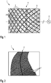
- Fig. 1 is a plan view of a portion of a device 1 for producing a curved fibre preform when bent.
- the device 1 comprises a plurality of first lamellae 2 and a plurality of second lamellae 3, which are configured to be pluggable into one another criss-cross in such a way that they are positioned on a shared plane and thus together form a grid 4.
- An axis 5, which intersects the shared plane of the grid 4 and about which the lamellae 2, 3 are resiliently bent, is further illustrated schematically. In this way, the local orientation of the lamellae 2, 3 deforms continuously, in such a way that the cells of the grid 4, which are square when detensioned, recognisably change to stretched or compressed rhombuses.
- a fibre semi-finished product 9, not shown here, can be adhered temporarily on the grid 4 by means of an adhesion means 6, here formed by way of example as an adhesive coating of the lamellae.
- the adhesion means 6 is configured in such a way that the local fibre orientation of the fibre semi-finished product also changes accordingly when the lamellae 2, 3 bend. A corresponding coefficient of friction is therefore provided between the grid and the adhesion means 6.
- the adhesive coating shown here is an adhesive strip permitted for fibre materials.
- the adhesive strip is formed to be thermally resistant.
- the adhesion means 6 may have additional elements and/or measures for adhering the fibre semi-finished product, which are discussed in greater detail in reference to the following embodiments.
- an adhesive strip permitted for fibre materials may also be provided as an anti-adhesive coating so as to reduce the friction and/or as a contact face so as to provide reliable contact.
- the deformation or shaping of the fibre semi-finished product 9 using a device 1 of this type is performed by means of a carrier, which comprises the grid 4 which is formed using the lamellae 2, 3 plugged into one another in the form of shearable bars plugged into one another.
- the bars preferably have the same orientation (for example ⁇ 45°) as the fibre orientation of at least some of the layers of the fibre semi-finished product 9 to be shaped.
- the fibre semi-finished product is therefore applied before the deformation in a fibre orientation corresponding to the orientation of the lamellae.
- the fibre semi-finished product is also sheared together.
- the maximum deformation / shearing of the grid 4 and thus also the desired curved shape, for example a required curvature of a former shape can also be established.
- Fig. 2 is a perspective view of the device according to Fig. 1 .
- This drawing likewise shows a bent state of the grid 4, which can be seen clearly here.
- Fig. 2 shows plug sockets 7 of the first and second lamellae 2, 3, which combine to form a depth corresponding to a thickness of the first and/or second lamellae 2, 3.
- These are slits which extend transverse to the longitudinal direction of the lamellae and which extend from a longitudinal face in each case approximately as far as the centre of a lamella 2, 3.
- the plug sockets of the first and second lamellae are formed with opposite orientations in each case, in such a way that they can be plugged into one another.
- a detensioning hole is provided in each case.
- Fig. 3 is a further perspective view of a device according to Fig. 1 and 2 .
- the device can be seen to comprise a plurality of first and second lamellae 2, 3. These are orientated in a ⁇ 45° orientation.
- the lamellae may each be a flexible bar.
- the material a wide range of bendable materials are suitable, such as high-grade steel, spring steel, glass-fibre-reinforced plastics material, carbon-fibre-reinforced plastics material, thermoplastics or the like.
- bendable materials such as high-grade steel, spring steel, glass-fibre-reinforced plastics material, carbon-fibre-reinforced plastics material, thermoplastics or the like.
- a neutral lamella 8 in the form of an individual bar is introduced in a third direction, and has a 0° orientation.
- the neutral lamella 8 is likewise formed using plug sockets, the lamellae 2, 3 of the grid 4 likewise being formed with additional plug sockets for receiving the neutral lamella 8.
- the neutral lamella 8 defines a neutral fibre of the deformation, in other words a line along which no shear deformation takes place. This preferably applies equally to the deformation of the grid 4 and of the fibre semi-finished product 9. Cells of the grid 4 which are positioned on a first side of the neutral lamella 8 are thus stretched when the lamellae 2, 3 bend, whilst cells of the grid positioned on a second side of the neutral lamella 8 are compressed.
- the fibre semi-finished product 9 can be sucked onto the grid 4 when an underpressure is applied by means of holes or ducts in said grid.
- the cells formed by the lamellae 2, 3 are fluidically connected via additional holes arranged between the plug sockets so as to make air circulation or pressure compensation possible between the cells.
- Fig. 4 is a perspective drawing of a portion of a device for producing a curved fibre preform in accordance with a further embodiment.
- Fig. 5 is a schematic cross-sectional drawing of the device of Fig. 4 .
- the device 1 also has a grid 4 as explained in reference to Fig. 1 to 3 .
- the adhesion means 6A of this embodiment additionally comprises a hollow box which is arranged under the grid and which is formed as an underpressure box 16. Sealing means 13 for sealing regions without fibre semi-finished product support are further provided.
- connection 12 to an underpressure source for example for connecting a vacuum cleaner tube as shown in Fig. 4 , is provided on a side face of the underpressure box 16.
- a perforation 14 as shown in Fig. 5 is provided in the form of an arrangement of holes, through which an underpressure applied to the underpressure box 16 can be transmitted into the grid 4.
- sealing means 13 formed as a covering are applied.
- Further additional sealing means 13 are further provided on the edge of the fibre semi-finished product 9, for sealing lateral cells of the grid 4 which are not covered by the semi-finished product, and fixed to the grid 4 using suitable fixing means 10.
- Fig. 6 is a perspective view of the device 1 of Fig. 4 and 5 when detensioned
- Fig. 7 is a perspective view of the device 1 when bent.
- the perforation 14 is also covered by the covering in regions positioned alongside the grid. Otherwise, holes positioned outside the grid 4 would suck up false air and reduce the suction force available for the fibre semi-finished product 9 positioned on the grid 4.
- the covering provided as sealing means 13 is accordingly formed so as to be displaced together with the deformation of the grid 4, as is indicated in Fig. 5 by the horizontal smaller arrows.
- the covering is further formed flexibly, in this case for example in the form of a flexible film. Further, in this case the covering consists for example of a plurality of sub-pieces which are displaceable with respect to one another.
- Fig. 8 is a drawing of a step of applying a fibre preform 9 to the grid 4 in the device of Fig. 4 to 6 .
- Fig. 9 is a detail of the edge of the fibre semi-finished product of Fig. 8 applied to the grid 4.
- Fig. 10 shows the fibre semi-finished product 9 of Fig. 8 and 9 with an edge covered with additional sealing means 13.
- the additional sealing means 13 serve to prevent false air from being sucked up at the edge of the grid 4, in particular in the gap shown in Fig. 9 between the straight end of the fibre semi-finished product 9 and the jagged edge of the grid 4 to which underpressure is applied.
- This additional sealing means 13 is likewise formed as a covering, but unlike the film of Fig. 4 is formed as a resilient plastics material mat in this case by way of example.
- the additional sealing means 13 may be positioned at the edge of the grid 4, as shown here, or else also be positioned on further portions of the grid 4 in further embodiments. Accordingly, the additional sealing means 13 may also be a flexible or multi-part covering.
- Fig. 11 is a schematic cross-sectional view of a device 1 for producing a curved fibre preform in accordance with a further embodiment.
- This embodiment differs from the embodiments described previously in relation to Fig. 4 to 11 by way of an additional membrane 11, which is provided between the grid 4 and the fibre preforms 9.
- the membrane 11 is formed air-permeable and deformable. It serves to brace the fibre semi-finished product in compressed regions of the grid, so as to prevent local swelling into grid gaps, in other words into cavities of the individual cells.
- Fig. 12 is a detail of an embodiment of a membrane 11 applied to the grid 4 of the device 1.
- the membrane 11 is formed as a metal grid by way of example.
- the threads of the metal grid have an identical orientation to the lamellae 2, 3 of the grid 4.
- the fibre semi-finished product 9 is braced from below in the grid gaps. Since the threads of the metal grid extend in the lamellae direction, the metal grid and thus also the lamellar grid 4 still remain deformable, however.
- a rubber membrane for example perforated or slitted, may be used.
- this is biased in accordance with a predetermined curvature of the fibre preform to be produced, so as to compensate the deformation of the grid 4 without swellings.
- the rubber membrane would subsequently have to be tensioned onto the grid 4 in such a way that the deformation of the rubber membrane is defined by the grid and thus subsequently also corresponds to the deformation of the textile (in other words not to the natural deformation of rubber).
- Fig. 13 is a schematic cross-sectional view of a device 1 for producing a curved fibre preform in accordance with another further embodiment.
- the distinguishing adhesion means 6B of this embodiment comprises a planar bed, which supports the grid, and has a contact face 15, which contacts the fibre semi-finished product 9 on a side opposite the grid 4.
- the contact face 15 is for example formed as a stamp which covers the size of the grid in both states, which is for example in the form of a solid body plate, and which has an anti-adhesive coating. In this way, a coefficient of friction between the contact face 15 and the fibre semi-finished product 9 is less than a coefficient of friction between the grid 4 and the fibre semi-finished product 9.
- mechanical pressure symbolised by vertical arrows in Fig. 13
- static friction is thus built up between the grid 4 and the fibre semi-finished product 9.
- a membrane 11 for supporting the fibre semi-finished product 9 on the grid 4 may optionally also be provided.
- an (optionally biased) rubber membrane is used, but this does not need to be perforated.
- fibre preforms for C profiles for formers can be produced, for example for producing 90° portions of a former.
- the produced fibre preform may subsequently be processed further to form the desired component, for example by cutting away edge regions, optionally by further shaping to form the subsequent component shape.
- this may include collaring the flange of the C profile for a former portion.
- a fibre semi-finished product may also be heated while positioned on the bent grid 4 so as to activate a binder which is located in the textile of the fibre semi-finished product and which fixes the deformation.
- the curved fibre preform can subsequently be received by a conventional gripper and transported onwards and/or processed further.
- a further conceivable embodiment of the device in the context of the present invention is a simultaneous formation of the device as an end effector.
- the device 1 is for example rotated together with the suction substructure of an adhesion means 6A, in other words together with the underpressure box 16 and the sealing means 13, after deformation together with the curved fibre preform.
- the fibre preform is subsequently transported onwards, for example directly positioned on a further component preform, by means of the end effector formed integrally with the device. Therefore, in this embodiment, the curved fibre preform may also only be heated once it is on the component preform, in such a way that the shape of the fibre preform is fixed simultaneously with fixing on the component preform.
- the component preform may be in the form of already deposited but not yet connected further layers for the component which is to be produced.
- an advantageous embodiment may involve applying this membrane biased only in part or in portions to the grid.
- the grid 4 is prevented from shortening on the radially inner side in the longitudinal direction, for example on the inside of the bending in the direction of the inner flange of a former preform.
- the membrane is thus compressed and can buckle in the absence of bias.
- the membrane being biased, it instead always remains planar, in such a way that buckling is prevented and the fibre semi-finished product is always optimally supported.
- the bias of the rubber membrane can be provided in such a way that on the inner side of the curvature the tension is at a maximum at the start of the deformation and is near-zero when the end state of the deformation is reached.
- the bias may accordingly be provided the other way around, in such a way that there it is near-zero at the start of the deformation and becomes a maximum when the end state of the deformation is achieved.
- the bias of the membrane may also be provided to be exactly as great on the outside as on the inside, in such a way that when the grid is non-deformed or relaxed it also remains straight in the absence of external forces.
Landscapes
- Engineering & Computer Science (AREA)
- Mechanical Engineering (AREA)
- Chemical & Material Sciences (AREA)
- Composite Materials (AREA)
- Moulding By Coating Moulds (AREA)
- Shaping Of Tube Ends By Bending Or Straightening (AREA)
- Nonwoven Fabrics (AREA)
- Reinforced Plastic Materials (AREA)
Description
- The present invention relates to a device for producing a curved fibre preform from a bi- or multidirectional fibre semi-finished product and to a corresponding method for producing a curved fibre preform from a bi- or multidirectional fibre semi-finished product.
- Although the present invention is described in greater detail hereinafter in relation to fibre preforms, also generally referred to as preforms, for former structures of an aircraft or spacecraft, it is not limited thereto but rather is transferrable to various curved fibre preforms, in particular for fuselage components of an aircraft or spacecraft.
- For producing former structures, textile blanks of a bi- or multidirectional fibre semi-finished product are draped onto the desired former shape. The draping is currently usually carried out by hand. A necessary step in this context is the production of the former-specific curvature so as to obtain a curved fibre preform. For this purpose, shearing and/or deformation of the fibre semi-finished product are generally required. Further, adaptation to the precise shape of each individual component to be produced is also carried out, in particular subsequently.
-
DE 10 2011 119 220 A1 describes devices for producing curved components from a fibre composite material. - Against this background, the object of the present invention is to provide an improved device for manufacturing a curved fibre preform from a bi- or multidirectional fibre semi-finished product which makes simplified and in particular automatable manufacture possible.
- According to the invention, this object is achieved by a device for producing a curved fibre preform from a bi- or multidirectional fibre semi-finished product, in particular for a fuselage component of an aircraft or spacecraft, having the features of
claim 1, and/or by a method for producing a curved fibre preform, in particular by means of a device according to the invention, having the features ofclaim 12. - Accordingly, a device for producing a curved fibre preform from a bi- or multidirectional fibre semi-finished product, in particular for a fuselage component of an aircraft or spacecraft, is provided, comprising a plurality of first lamellae and a plurality of second lamellae which are formed to be couplable to one another, in particular pluggable into one another, criss-cross in such a way that they are positioned on a shared plane and thus form a grid, the lamellae at least in part being formed resiliently bendable about an axis intersecting the shared plane in such a way that a local orientation of the lamellae in the grid changes, in particular continuously; and an adhesion means which is formed for temporarily adhering the fibre semi-finished product to the grid and is configured in such a way that the local fibre orientation of the fibre semi-finished product also changes accordingly when the lamellae bend.
- Further, a method for producing a curved fibre preform, in particular by means of a device according to the invention, is provided, comprising the following method steps: applying a bi- or multi-directional fibre semi-finished product to a grid of a plurality of first lamellae and a plurality of second lamellae, which are coupled to one another, in particular plugged into one another, criss-cross and positioned on a shared plane, temporarily adhering the fibre semi-finished product to the grid; and resiliently bending the lamellae at least in part about an axis intersecting the shared plane, a local orientation of the lamellae in the grid changing, in particular continuously, and a local fibre orientation of the fibre semi-finished product also changing accordingly when the lamellae bend.
- The idea behind the present invention is to provide a deformation of a grid serving as a carrier structure for the fibre semi-finished product in a manner corresponding to the desired deformation of the fibre semi-finished product. For this purpose, the lamellae of the grid are formed and orientated as exactly as possible in accordance with the orientation of the fibres contained in the fibre semi-finished product, in such a way that a shared orientation of the lamellae and fibres, which can be deformed jointly, is provided. The lamellae and fibres thus deform in the same manner during the bending. Advantageously, in this way a curved fibre orientation of the curved fibre preform is very precisely adjustable or controllable, in such a way that the quality of the fibre preform and thus also of the fuselage component to be produced is improved, in particular in terms of mechanical properties.
- Advantageously, in particular the deformation of a silicone core used in previous devices is further avoided, the deformation of said core not geometrically corresponding to a shear deformation of a fibre semi-finished product.
- Further, the shaping principle according to the invention makes greatly simplified automation of the process possible, as well as greatly improved reproducibility of the shaping. In this way, reduction in staffing costs and acceleration of the production process can be achieved.
- By means a device or method according to the invention, in particular curved fibre preforms for C profiles or Z profiles of formers can be produced. In this way, portions of a former, for example portions of a former curved through 90°, can be produced in an automated manner and with greater reproducibility using fibre preforms correspondingly curved through 90°. Subsequently, they can also be shaped into the desired profile, for example a C profile or Z profile.
- The lamellae being on a shared plane should be understood to mean that they provide a shared grid face when coupled, in particular plugged into one another. This may also merely be a shared local plane, in such a way that arched shared grid surfaces, for example for manufacturing multiple curved components, are also conceivable. The surface of the grid may therefore also imitate a three-dimensionally curved surface. For example, for this purpose the lamellae may be formed at different heights in different regions of the grid, and thus be provided adapted to a desired component shape.
- Further, thin lamellae, in particular in the form of rods, would also be conceivable at least in portions, in such a way that they can bend in not just one but a plurality of directions. In this way, three-dimensional bendings are also possible. Accordingly, the grid can also be shaped to a three-dimensional shape and/or itself deform three-dimensionally as a result of bending of the lamellae.
- Bending at least in part about an axis intersecting the shared plane should thus be understood to mean that the bending axis may be orientated perpendicular to the grid or else at an angle to portions of the grid or to the entire grid. The point of intersection between the axis and the shared plane need not and indeed generally will not lie within the grid, but rather in an imaginary continuation of the grid in the plane thereof.
- As well as continuously bendable lamellae, for example a grid would also be conceivable which comprises lamellae consisting of a plurality of short lamellar pieces which are connected using rotary joints. The individual lamellar pieces would therefore remain straight in spite of the bending of the lamellae as a whole, and the deformation would be implemented at the rotary joints.
- Adhesion of the fibre semi-finished product to the grid should be understood to mean that there is static friction between the fibre semi-finished product and the grid. This may, but need not necessarily, act directly between the grid and the fibre semi-finished product, and instead may optionally also be transmitted via an intermediate layer, for example a membrane arranged in between.
- In particular, an additional advantage of the present invention is the particularly simple possibility of automation of shaping steps for curved fibre preforms which were previously usually carried out manually.
- An adhesion means should be understood to mean an individual device or measure or a combination thereof which leads to adhesion of the semi-finished product to a surface of the grid which is sufficient for the desired deformation during bending of the lamellae. This can be configured in various ways. In a simple embodiment, the adhesion means may be formed as a bonding means of the grid itself or as a soluble adhesion promoter applied thereto. For example, for this purpose sticky, rough, jagged and/or needle portions may be provided in an application region, provided on the grid, which is non-critical for the fibre semi-finished product, for example at an edge of the fibre semi-finished product. In further embodiments, an adhesion means may contain means or measures provided externally to the grid, for example on the basis of underpressure for sucking the fibre semi-finished product on or of mechanical pressure for pressing the fibre semi-finished product on.
- Preferably, the fibre semi-finished product is applied to or orientated on the grid in such a way that the fibres at least in part extend parallel to the lamellae. For example, ±45° fibres of a fibre roving are orientated along the ±45° lamellae of the grid.
- The fibre semi-finished product to be deformed for producing the curved fibre preform is in particular formed as a ±45° biaxial roving or as a ±45°, 90° triaxial roving. In this case, the lamellae of the grid preferably also extend at ±45° angles. In particular, the fibre semi-finished product does not contain any 0° fibres, which would prevent stretching or compression of the roving.
- During bending of the lamellae, the lamellae deform in a manner corresponding to a desired progression of the fibres in the curved state. The fibres of the fibre semi-finished product or fibre roving therefore deform in a desired manner during the deformation of the cells of the grid, in such a way that the fibre direction is ideally locally reorientated in a manner corresponding to the deformation.
- In particular, cells which are positioned radially externally, in other words outside a neutral fibre, of a grid having ±45° lamellae, which form rectangular, for example square cells of the grid before the bending, are stretched to form rhombuses which are elongate in the peripheral direction. Thus, even radially externally positioned ±45° fibres, for example of a ±45° biaxial roving, are sheared or reorientated in such a way that they cross in the manner of elongate rhombuses. Conversely, radially internal cells of the grid are compressed to form rhombuses which are squashed in the peripheral direction, and this in the same manner leads to corresponding reorientation or shearing of the fibres. In this way, in particular radial fanning out of the ±45° fibres or of the fibre directions thereof is achieved.
- In the case of a ±45°, 90° triaxial roving, in this context the 90° fibres would for example also be displaced radially in a manner corresponding to the deformation. The 90° fibre layers would thus slide with respect to the ±45°. The orientation of the grid would thus correspond to the orientation of the ±45° layers, the orientation of the 90° layer not being imitated by the grid.
- In further embodiments, it would also be conceivable to provide a 0°, 90° biaxial roving. In this case, the lamellae preferably also extend at 0° and 90° angles. Thus, the 90° lamellae and fibres, in particular exclusively, would fan out radially during the bending of the lamellae, and the 0° fibres would merely be radially displaced.
- A suitable orientation of the lamellae in the grid is thus dependent in particular on the fibre orientation of the fibre semi-finished product to be shaped, and is preferably unidirectional for this purpose.
- Naturally, in each case multidimensional rovings having fibre directions and any further fibre directions would also be conceivable, as long as the fibre layers which are not orientated parallel to the grid bars are applied in the textile in such a way that they can slide relative to the other layers during deformation/shearing (for example by way of an active pattern having relatively slack thread tension in a multiaxial roving), in such a way that none of the fibre directions directly obstructs the deformation. By contrast, for example a 0° fibre direction in a ±45° grid would obstruct deformation if it were knitted onto the remaining ±45° layers in such a way that it could not slide.
- After the deformation or curvature, the fibre preform can be processed further to form the desired component, for example by cutting off edge regions of the fibre preform and/or by further deformation to form the subsequent component shape, for example collaring the flange of a C profile for producing a former portion and/or connection to further, already deposited component layers and/or curing a binder.
- Advantageous embodiments and developments may be derived from the further dependent claims and from the description with reference to the drawings.
- In a development, for coupling to one another the first and second lamellae may comprise corresponding plug sockets which can be plugged into one another. In particular, the plug sockets combine to form a depth corresponding to a thickness of the first and/or second lamellae. In particular, the plug sockets are formed as slits. For example, the slits extend from a longitudinal face in each case approximately as far as the centre of a lamella. Preferably, at the base of a slit a detensioning hole may be provided to prevent grooving effects which occur during bending.
- In an advantageous embodiment, a neutral lamella is introduced into the grid, and is arranged in the region of a theoretical or actual neutral fibre of the curved fibre preform to be produced. In particular, this is an irregular lamella, i.e. one arranged so as to interrupt the regular arrangement of the lamellae in the grid. Preferably, this neutral lamella extends at a 0° orientation, in other words in the peripheral direction when the lamellae are bent. The neutral lamella is formed in such a way that cells of the grid which are positioned on a first side of the neutral lamella are stretched, in particular in relation to a reference direction, during bending, and cells of the grid which are positioned on a second side of the neutral lamella are compressed, in particular in relation to an identical reference direction, during bending. In particular, cells positioned directly on the neutral lamella are only insignificantly deformed in accordance with the bending. Advantageously, the shaping can thus be provided in a predefined manner.
- The stretching and compression are preferably each to be understood in the peripheral direction. Accordingly, the side lengths of the individual cells remain constant. Since the plug connections are formed stationary with respect to the lamellae, a stretched cell is therefore stretched in the peripheral direction and compressed in the radial direction, whilst a compressed cell is compressed in the peripheral direction and stretched in the radial direction. When the cells shear, they are therefore always stretched in one direction and shortened in another direction perpendicular thereto. The peripheral direction therefore forms the reference direction in this case.
- A stationary positioning of the plug connections with respect to the lamellae is advantageous since the fibres of the unshaped textile semi-finished product itself are thus not compressed or stretched but merely reorientated or bent and sheared with respect to one another.
- For example, for being received in the grid, the neutral lamella may likewise be provided with plug sockets. Accordingly, in regions in which the neutral lamella is to be inserted, the lamellae of the grid are likewise formed with additional plug sockets for receiving the neutral lamella.
- In one embodiment, a deformable membrane provided as a support face for the fibre semi-finished product is provided on the grid. In this manner, swellings of the fibre semi-finished product into the cavities of the cells or gaps in the lamellae are effectively prevented. It is additionally conceivable to provide the membrane as a grid fabric, for example a wire grid, which is deformable in the same way as the fibres. In particular, however, the membrane may also be formed as a membrane which is resiliently biased to compensate the bending of the lamellae. For example, it may contain an elastomer for this purpose. In a further embodiment, this may for example be a resilient perforated or slitted (rubber or elastomer) membrane. In particular, it may be biased, preferably counter to the desired bending direction. In particular, the membrane may be biased on the side of the neutral fibre which experiences compression in the peripheral direction during the bending process, in such a way that after the bending process is carried out it is actually detensioned or still slightly biased. In this way, the deformation of the membrane occurring when the lamellae are bent is compensated, in such a way that no corrugations or folds are raised and swelling into the cavity of the cells of the grid is also prevented.
- In an advantageous embodiment, the adhesion means comprises an underpressure box which fluidically contacts the grid. The underpressure box is formed in such a way that an underpressure can thus be applied in each cell of the grid provided for supporting the fibre semi-finished product. In particular, for this purpose an underpressure connection, to which an underpressure source can be connected, is provided on the underpressure box. Advantageously, in this way the fibre semi-finished product is sucked onto the grid and the adhesions to the grid which are desired for the deformation are thus provided.
- In a development, the underpressure box is perforated in the region of cells of the grid which are provided for supporting the fibres. Sealing means for in particular locally sealing the perforation and/or the grid are further provided in regions without fibre semi-finished product support, in other words in regions where the fibre semi-finished product is not currently being supported and/or in edge regions of the fibre semi-finished product. For example, in this way, at the edge of the fibre semi-finished product, cells of the grid which are merely half-covered by the fibre semi-finished product can also be sealed. In this way, it is provided that an underpressure is present substantially at the fibre semi-finished product. Advantageously, in this way the underpressure is merely transmitted to the required points on the grid. This means that the fibre semi-finished product itself is basically adhered to the grid not by the sealing means but rather by the underpressure, although naturally there may also be a slight adhesion due to the sealing means on the covered edge.
- In one embodiment, the entire grid may be flooded with underpressure. For this purpose, the individual cells of the grid may be formed fluidically connected via corresponding holes in the lamellae.
- In further embodiments, it would also be conceivable merely to apply underpressure to the currently required cells of the grid. For example, for this purpose the cells may each have their own activatable and deactivatable underpressure supply opening.
- The grid and/or the underpressure box may preferably also be anti-adhesively coated, making it possible to bend the grid on the underpressure box without resistance.
- Further, a wide range of sealing means are conceivable. For example, they may be one or more cover films or cover plates which locally seal the holes of the perforation. However, controllable flat slides or valves, for example magnetic valves, are also conceivable as sealing means which can open and close individual ones of or groups of openings of the perforation for underpressure supply.
- In an advantageous embodiment, the perforation of the underpressure box is provided in a first region, where the cells of the grid which are provided for supporting the fibre semi-finished product are located when the lamellae are detensioned or not bent, and in a second region, where the cells of the grid which are provided for supporting the fibre semi-finished product are located when the lamellae are bent. This has the advantage that in this way an ideal application of pressure is made possible in both states and also in any intermediate states of the grid.
- In a development, the sealing means seal the perforation which is positioned alongside the cells of the grid which are provided for supporting the fibre semi-finished product in each state of the grid. Advantageously, the perforation is thus selectively sealed in the regions not required for applying the underpressure in each case, depending on the state of the grid. In this way, distribution of the underpressure to the openings of the perforation which are required in each case is provided.
- In one embodiment, the sealing means comprise an air-impermeable local covering of the perforation and/or of the grid. Advantageously, a covering of this type provides a sealing means which is particularly simple to implement and which is additionally flexibly usable and displaceable. As a result, in particular adaptation to the various states of the grid can also be implemented in a simple manner. For example, a film may be applied over the regions of the perforation and if applicable of the grid which are not required, and be advanced in accordance with the deformation when the lamellae are bent. In particular, the covering may be a flexible film. The advantage of a flexible film of this type is that in this way the device is also easily adjustable to different component sizes or shapes, since the covering can thus seal different contours of a fibre semi-finished product. As a further possibility, the film could consist of a plurality of overlapping pieces, in such a way that the required movement takes place at the overlapping joints.
- Alternatively or in addition, the sealing means may comprise selectively actuable valves of the perforation and/or of the grid. For example, these may be valves which are actuable electronically for opening and closing, for example magnetic valves, which are introduced into the openings of the perforation.
- In one embodiment, the adhesion means comprises a bonding means of the grid itself. For example, a bonding means may be provided in the form of sticky, rough, jagged and/or needle portions in an application region, provided on the grid, which is non-critical for the fibre semi-finished product, preferably at an edge of the fibre semi-finished product. Force transmission from the grid to the semi-finished product is thus improved, and slipping is additionally prevented.
- In a further embodiment, the adhesion means comprises a contact face which contacts the fibre semi-finished product on a side opposite the grid. A coefficient of friction between the contact face and the fibre semi-finished product is configured to be less than a coefficient of friction between the grid and the fibre semi-finished product. Naturally, this also applies to the coefficient of friction between a grid, any membrane connected in between, and the fibre semi-finished product. It is advantageous that in this way particularly simple construction and control of the adhesion means are made possible. The contact face may for example be formed as a stamp which covers the size of the grid in both states, which is for example in the form of a solid body plate, and which has an anti-adhesive coating, for example containing polytetrafluoroethylene or another coating agent having an anti-adhesive effect, on the surface thereof. Alternatively, a very smooth surface having a low coefficient of friction and a high wear resistance may be provided, such as glass or polished high-grade steel. On an opposite side of the grid, in particular a bracing, for example a suitable planar bed, preferably also anti-adhesively coated, is provided.
- An embodiment having a heatable configuration of the stamp for activating a binder in the deformed state is also conceivable. Heating may be provided before the transport step or after the transport step before the fixing is released. Locally limited heating may be provided in this context.
- Further, a rotated arrangement is also possible, in such a way that the contact face serves as a base plate and initially the fibre semi-finished product and subsequently the grid are applied to the contact face.
- In an advantageous embodiment, the grid and/or the adhesion means are formed as part of an end effector for transporting the previously curved fibre preform in the bent state of the lamellae. In this way, a particular synergy is produced, since no additional handover to an end effector is required. Further, in this way the component can be transferred to the location of use thereof or to a further shaping device in the predetermined shaped or curved configuration.
- For example, in one embodiment, for this purpose the entire device may be rotated after the shaping, in such a way that the bent grid can be raised together with the deformed fibre semi-finished product.
- In a further embodiment, the grid is already provided positioned above for shaping, in other words applied to the fibre semi-finished product from above for deformation. In this case, for example a suitable underlay having a low coefficient of friction is provided for bracing the underside of the fibre semi-finished product. In the case of a bonding device based on underpressure, this underlay may be formed air-permeable.
- In an embodiment of the method for producing a curved fibre preform, the fibre semi-finished product is orientated in such a way on the grid that the bi- or multidirectional fibres of the fibre semi-finished product extend parallel to the lamellae at least in part.
- Further, in an embodiment of the method, alternatively or in addition, a theoretical or actual neutral fibre of the fibre semi-finished product is arranged and orientated on an in particular irregular, neutral lamella of the grid. During the resilient bending, fibres positioned on the first side of the neutral lamella are thus deformed in accordance with a stretching of the cells of the grid which acts there, in particular in relation to a reference direction. Further, fibres positioned on a second side of the neutral lamella deform in accordance with a compression of the cells of the grid which acts there, in particular in relation to an identical reference direction.
- Further, in an embodiment of the method, the temporary adhesion is provided by means of mechanical pressure acting on the fibre semi-finished product or fluidic underpressure acting on the fibre semi-finished product.
- Finally, in an embodiment of the method according to the invention, a step of transporting the curved fibre preform by means of the grid when the lamellae are bent and/or by means of an adhesion means used for adhesion is provided.
- Alternatively or in addition, in one embodiment, before a step of transporting the curved fibre preform, a handover to a separate end effector may also be performed, which is carried out in such a way that detensioning and reverse deformation of the fibre preform in the meantime are prevented.
- In an advantageous embodiment, a further shaping step or a plurality of further shaping steps follow the step of transporting the curved fibre preform. For example, shaping may be provided in a further plane to produce a desired profile cross section, in particular a C or Z profile.
- The above embodiments and developments may, within reason, be combined with one another in any desired manner. In particular, all features and devices and processes of the device according to the invention are transferrable to the method according to the invention and vice versa. Further possible configurations, developments and implementations of the invention also include combinations not explicitly mentioned of features of the invention which are described above or hereinafter in relation to the embodiments. In particular, a person skilled in the art will also add individual aspects to each basic form of the present invention as improvements or supplements.
- Hereinafter, the present invention is described in greater detail by way of the embodiments set out in the schematic drawings, in which:
-
Fig. 1 is a plan view of a portion of a device for producing a curved fibre preform; -
Fig. 2 is a perspective view of a device according toFig. 1 ; -
Fig. 3 is a further perspective view of the device ofFig. 2 ; -
Fig. 4 is a perspective drawing of a portion of a device for producing a curved fibre preform in accordance with a further embodiment; -
Fig. 5 is a schematic cross-sectional drawing of the device ofFig. 4 ; -
Fig. 6 is a perspective view of the device ofFig. 4 and5 when detensioned; -
Fig. 7 shows the device ofFig. 6 when bent; -
Fig. 8 is a drawing of a step of applying a fibre preform to the grid for the device ofFig. 4 to 7 ; -
Fig. 9 is a detail of the edge of the fibre semi-finished product ofFig. 8 applied to the grid; -
Fig. 10 shows the fibre semi-finished product ofFig. 8 and 9 with an edge covered with additional sealing means; -
Fig. 11 is a schematic cross-sectional view of a device for producing a curved fibre preform in accordance with a further embodiment; -
Fig. 12 is a detail of a membrane applied to the grid of the device; and -
Fig. 13 is a schematic cross-sectional view of a device for producing a curved fibre preform in accordance with another further embodiment. - The accompanying drawings are intended to convey an improved understanding of the embodiments of the invention. They illustrate embodiments and serve in conjunction with the description to explain principles and concepts of the invention. Other embodiments and many of the stated advantages may be derived from the drawings. The elements of the drawings are not necessarily shown to scale with one another.
- In the drawings, unless stated otherwise, like, functionally equivalent and identically acting elements, features and components are provided with like reference numerals.
-
Fig. 1 is a plan view of a portion of adevice 1 for producing a curved fibre preform when bent. - This is a
device 1 for producing a curved fibre preform from a bi- or multidirectional fibre semi-finished product (not shown here) for a fuselage component of an aircraft or spacecraft, for example a former portion. - The
device 1 comprises a plurality offirst lamellae 2 and a plurality of second lamellae 3, which are configured to be pluggable into one another criss-cross in such a way that they are positioned on a shared plane and thus together form agrid 4. Anaxis 5, which intersects the shared plane of thegrid 4 and about which thelamellae 2, 3 are resiliently bent, is further illustrated schematically. In this way, the local orientation of thelamellae 2, 3 deforms continuously, in such a way that the cells of thegrid 4, which are square when detensioned, recognisably change to stretched or compressed rhombuses. - A fibre
semi-finished product 9, not shown here, can be adhered temporarily on thegrid 4 by means of an adhesion means 6, here formed by way of example as an adhesive coating of the lamellae. The adhesion means 6 is configured in such a way that the local fibre orientation of the fibre semi-finished product also changes accordingly when thelamellae 2, 3 bend. A corresponding coefficient of friction is therefore provided between the grid and the adhesion means 6. - Purely by way of example, the adhesive coating shown here is an adhesive strip permitted for fibre materials. Preferably the adhesive strip is formed to be thermally resistant.
- In further embodiments, however, the adhesion means 6 may have additional elements and/or measures for adhering the fibre semi-finished product, which are discussed in greater detail in reference to the following embodiments. In this case, an adhesive strip permitted for fibre materials may also be provided as an anti-adhesive coating so as to reduce the friction and/or as a contact face so as to provide reliable contact.
- The deformation or shaping of the fibre
semi-finished product 9 using adevice 1 of this type is performed by means of a carrier, which comprises thegrid 4 which is formed using thelamellae 2, 3 plugged into one another in the form of shearable bars plugged into one another. The bars preferably have the same orientation (for example ±45°) as the fibre orientation of at least some of the layers of the fibresemi-finished product 9 to be shaped. The fibre semi-finished product is therefore applied before the deformation in a fibre orientation corresponding to the orientation of the lamellae. - If the grid together with the fibre semi-finished product adhering thereto is sheared by bending, the fibre semi-finished product is also sheared together. By means of stops, the maximum deformation / shearing of the
grid 4 and thus also the desired curved shape, for example a required curvature of a former shape, can also be established. -
Fig. 2 is a perspective view of the device according toFig. 1 . - This drawing likewise shows a bent state of the
grid 4, which can be seen clearly here. - Further,
Fig. 2 shows plug sockets 7 of the first andsecond lamellae 2, 3, which combine to form a depth corresponding to a thickness of the first and/orsecond lamellae 2, 3. These are slits which extend transverse to the longitudinal direction of the lamellae and which extend from a longitudinal face in each case approximately as far as the centre of alamella 2, 3. In this context, the plug sockets of the first and second lamellae are formed with opposite orientations in each case, in such a way that they can be plugged into one another. At the base of a slit, a detensioning hole is provided in each case. -
Fig. 3 is a further perspective view of a device according toFig. 1 and 2 . - The device can be seen to comprise a plurality of first and
second lamellae 2, 3. These are orientated in a ±45° orientation. For example, the lamellae may each be a flexible bar. As the material, a wide range of bendable materials are suitable, such as high-grade steel, spring steel, glass-fibre-reinforced plastics material, carbon-fibre-reinforced plastics material, thermoplastics or the like. By way of example, in the embodiment shown over 100 lamellae, which are highly flexible, are plugged into one another. The resulting grid is planar on both sides. - In the
grid 4, a neutral lamella 8 in the form of an individual bar is introduced in a third direction, and has a 0° orientation. The neutral lamella 8 is likewise formed using plug sockets, thelamellae 2, 3 of thegrid 4 likewise being formed with additional plug sockets for receiving the neutral lamella 8. - The neutral lamella 8 defines a neutral fibre of the deformation, in other words a line along which no shear deformation takes place. This preferably applies equally to the deformation of the
grid 4 and of the fibresemi-finished product 9. Cells of thegrid 4 which are positioned on a first side of the neutral lamella 8 are thus stretched when thelamellae 2, 3 bend, whilst cells of the grid positioned on a second side of the neutral lamella 8 are compressed. - The fibre
semi-finished product 9 can be sucked onto thegrid 4 when an underpressure is applied by means of holes or ducts in said grid. For this purpose, in this embodiment the cells formed by thelamellae 2, 3 are fluidically connected via additional holes arranged between the plug sockets so as to make air circulation or pressure compensation possible between the cells. -
Fig. 4 is a perspective drawing of a portion of a device for producing a curved fibre preform in accordance with a further embodiment.Fig. 5 is a schematic cross-sectional drawing of the device ofFig. 4 . - In this embodiment, the
device 1 also has agrid 4 as explained in reference toFig. 1 to 3 . - However, the adhesion means 6A of this embodiment additionally comprises a hollow box which is arranged under the grid and which is formed as an
underpressure box 16. Sealing means 13 for sealing regions without fibre semi-finished product support are further provided. - For applying underpressure to the
grid 4, aconnection 12 to an underpressure source, for example for connecting a vacuum cleaner tube as shown inFig. 4 , is provided on a side face of theunderpressure box 16. - On the upper face of the
underpressure box 16, aperforation 14 as shown inFig. 5 is provided in the form of an arrangement of holes, through which an underpressure applied to theunderpressure box 16 can be transmitted into thegrid 4. Via cells which are not covered by thesemi-finished product 9 and holes of theperforation 14 which are not in contact with thegrid 4, sealing means 13 formed as a covering are applied. Further additional sealing means 13 are further provided on the edge of the fibresemi-finished product 9, for sealing lateral cells of thegrid 4 which are not covered by the semi-finished product, and fixed to thegrid 4 using suitable fixing means 10. - In this way, the fibre
semi-finished product 9 placed on thegrid 4 is sucked onto thegrid 4, as is symbolised by the perpendicular thick arrows inFig. 5 , in such a way that static friction occurs between the fibresemi-finished product 9 and the lateral flanks of thelamellae 2, 3, and adhesion of the fibresemi-finished product 9 to thegrid 4 thus occurs. -
Fig. 6 is a perspective view of thedevice 1 ofFig. 4 and5 when detensioned, whilstFig. 7 is a perspective view of thedevice 1 when bent. - As a result of the deformation of the grid during bending, the face covered by the
grid 4 is also displaced on theunderpressure box 16. Thus, there are holes of theperforation 14 of theunderpressure box 16 which are only positioned below thegrid 4 when detensioned as inFig. 6 or at the start of the deformation, and which are positioned alongside thegrid 4 when bent or at the end of the deformation. Conversely, there are also holes of the perforation which are positioned outside thegrid 4 at the start of the deformation and are positioned under it at the end of the deformation. - For sealing the holes positioned alongside the
grid 4 in each case, theperforation 14 is also covered by the covering in regions positioned alongside the grid. Otherwise, holes positioned outside thegrid 4 would suck up false air and reduce the suction force available for the fibresemi-finished product 9 positioned on thegrid 4. The covering provided as sealing means 13 is accordingly formed so as to be displaced together with the deformation of thegrid 4, as is indicated inFig. 5 by the horizontal smaller arrows. - Since the shape and the lengths of the outer edges of the
grid 4 change during bending, the covering is further formed flexibly, in this case for example in the form of a flexible film. Further, in this case the covering consists for example of a plurality of sub-pieces which are displaceable with respect to one another. -
Fig. 8 is a drawing of a step of applying afibre preform 9 to thegrid 4 in the device ofFig. 4 to 6 .Fig. 9 is a detail of the edge of the fibre semi-finished product ofFig. 8 applied to thegrid 4. - It can be seen that at the edge of the fibre semi-finished product there are cells of the
grid 4 which are merely covered in part. For these regions, in the embodiment shown an additional sealing means 13 is provided, which is shown inFig. 10 . -
Fig. 10 shows the fibresemi-finished product 9 ofFig. 8 and 9 with an edge covered with additional sealing means 13. - The additional sealing means 13 serve to prevent false air from being sucked up at the edge of the
grid 4, in particular in the gap shown inFig. 9 between the straight end of the fibresemi-finished product 9 and the jagged edge of thegrid 4 to which underpressure is applied. This additional sealing means 13 is likewise formed as a covering, but unlike the film ofFig. 4 is formed as a resilient plastics material mat in this case by way of example. The additional sealing means 13 may be positioned at the edge of thegrid 4, as shown here, or else also be positioned on further portions of thegrid 4 in further embodiments. Accordingly, the additional sealing means 13 may also be a flexible or multi-part covering. -
Fig. 11 is a schematic cross-sectional view of adevice 1 for producing a curved fibre preform in accordance with a further embodiment. - This embodiment differs from the embodiments described previously in relation to
Fig. 4 to 11 by way of anadditional membrane 11, which is provided between thegrid 4 and thefibre preforms 9. - In this embodiment, which is based on suction by way of underpressure, the
membrane 11 is formed air-permeable and deformable. It serves to brace the fibre semi-finished product in compressed regions of the grid, so as to prevent local swelling into grid gaps, in other words into cavities of the individual cells. -
Fig. 12 is a detail of an embodiment of amembrane 11 applied to thegrid 4 of thedevice 1. - In this case the
membrane 11 is formed as a metal grid by way of example. The threads of the metal grid have an identical orientation to thelamellae 2, 3 of thegrid 4. - By means of the additional metal grid, the fibre
semi-finished product 9 is braced from below in the grid gaps. Since the threads of the metal grid extend in the lamellae direction, the metal grid and thus also thelamellar grid 4 still remain deformable, however. - In other embodiments, however, instead of a metal grid a rubber membrane, for example perforated or slitted, may be used. Preferably, this is biased in accordance with a predetermined curvature of the fibre preform to be produced, so as to compensate the deformation of the
grid 4 without swellings. The rubber membrane would subsequently have to be tensioned onto thegrid 4 in such a way that the deformation of the rubber membrane is defined by the grid and thus subsequently also corresponds to the deformation of the textile (in other words not to the natural deformation of rubber). - In a further embodiment, instead of a
membrane 11 of this type it is also conceivable to make thegrid 4 itself narrower-mesh, in other words from much smaller lamellae, in such a way that thegrid 4 has smaller cells or smaller gaps and the fibresemi-finished product 9 is thus better supported. -
Fig. 13 is a schematic cross-sectional view of adevice 1 for producing a curved fibre preform in accordance with another further embodiment. - The distinguishing adhesion means 6B of this embodiment comprises a planar bed, which supports the grid, and has a
contact face 15, which contacts the fibresemi-finished product 9 on a side opposite thegrid 4. - The
contact face 15 is for example formed as a stamp which covers the size of the grid in both states, which is for example in the form of a solid body plate, and which has an anti-adhesive coating. In this way, a coefficient of friction between thecontact face 15 and the fibresemi-finished product 9 is less than a coefficient of friction between thegrid 4 and the fibresemi-finished product 9. When mechanical pressure, symbolised by vertical arrows inFig. 13 , is applied via thecontact face 15, static friction is thus built up between thegrid 4 and the fibresemi-finished product 9. The deformation under mechanical pressure applied using the stamp can therefore be performed in the same manner described in relation to the preceding embodiments with application of underpressure. - Further, in this case a
membrane 11 for supporting the fibresemi-finished product 9 on thegrid 4 may optionally also be provided. Preferably, in this case an (optionally biased) rubber membrane is used, but this does not need to be perforated. - By means of a device in accordance with one of the above-described embodiments, in particular fibre preforms for C profiles for formers can be produced, for example for producing 90° portions of a former. Accordingly, the produced fibre preform may subsequently be processed further to form the desired component, for example by cutting away edge regions, optionally by further shaping to form the subsequent component shape. For example, this may include collaring the flange of the C profile for a former portion.
- Although the present invention has been described entirely by way of preferred embodiments in the above, it is not limited thereto, but can be modified in various ways.
- For example, a fibre semi-finished product may also be heated while positioned on the
bent grid 4 so as to activate a binder which is located in the textile of the fibre semi-finished product and which fixes the deformation. In this case, after cooling, the curved fibre preform can subsequently be received by a conventional gripper and transported onwards and/or processed further. - A further conceivable embodiment of the device in the context of the present invention is a simultaneous formation of the device as an end effector. For this purpose, the
device 1 is for example rotated together with the suction substructure of an adhesion means 6A, in other words together with theunderpressure box 16 and the sealing means 13, after deformation together with the curved fibre preform. The fibre preform is subsequently transported onwards, for example directly positioned on a further component preform, by means of the end effector formed integrally with the device. Therefore, in this embodiment, the curved fibre preform may also only be heated once it is on the component preform, in such a way that the shape of the fibre preform is fixed simultaneously with fixing on the component preform. For example, the component preform may be in the form of already deposited but not yet connected further layers for the component which is to be produced. - If elastomer or rubber membranes are used on the
grid 4, either below or above the fibresemi-finished product 9, an advantageous embodiment may involve applying this membrane biased only in part or in portions to the grid. As a result of the different deformation of the grid and of the material of the membrane, for example rubber, thegrid 4 is prevented from shortening on the radially inner side in the longitudinal direction, for example on the inside of the bending in the direction of the inner flange of a former preform. The membrane is thus compressed and can buckle in the absence of bias. As a result of the membrane being biased, it instead always remains planar, in such a way that buckling is prevented and the fibre semi-finished product is always optimally supported. - In one embodiment, the bias of the rubber membrane can be provided in such a way that on the inner side of the curvature the tension is at a maximum at the start of the deformation and is near-zero when the end state of the deformation is reached. On the outside of the curvature, the bias may accordingly be provided the other way around, in such a way that there it is near-zero at the start of the deformation and becomes a maximum when the end state of the deformation is achieved.
- In a further embodiment, however, the bias of the membrane may also be provided to be exactly as great on the outside as on the inside, in such a way that when the grid is non-deformed or relaxed it also remains straight in the absence of external forces.
-
- 1
- Device
- 2
- First lamellae
- 3
- Second lamellae
- 4
- Grid
- 5
- Axis
- 6
- Adhesion means
- 6A; 6B
- Adhesion means
- 7
- Plug sockets
- 8
- Neutral lamella
- 9
- Fibre semi-finished product
- 10
- Fixing means
- 11
- Membrane
- 12
- Underpressure connection
- 13
- Sealing means
- 14
- Perforation
- 15
- Contact face
- 16
- Underpressure box
Claims (15)
- Device (1) for producing a curved fibre preform from a bi- or multidirectional fibre semi-finished product, in particular for a fuselage component of an aircraft or spacecraft, comprising: a plurality of first lamellae (2) and a plurality of second lamellae (3) which are formed to be couplable to one another criss-cross in such a way that they are positioned on a shared plane and thus form a grid (4), the lamellae (2, 3) at least in part being formed resiliently bendable about an axis (5) intersecting the shared plane in such a way that a local orientation of the lamellae (2, 3) in the grid (4) changes; and an adhesion means (6; 6A; 6B) which is formed for temporarily adhering the fibre semi-finished product (9) to the grid and is configured in such a way that the local fibre orientation of the fibre semi-finished product also changes accordingly when the lamellae (2, 3) bend.
- Device according to claim 1, wherein for coupling to one another the first and second lamellae (2, 3) comprise corresponding plug sockets (7) which can be plugged into one another, in particular which combine to form a depth corresponding to a thickness of the first and/or second lamellae (2, 3).
- Device according to either of the preceding claims, wherein an in particular irregular neutral lamella (8) is introduced into the grid (4), and is arranged in the region of a theoretical or actual neutral fibre of the curved fibre preform to be produced, and is formed in such a way that cells of the grid (4) which are positioned on a first side of the neutral lamella (8) are stretched during bending and cells of the grid which are positioned on a second side of the neutral lamella (8) are compressed during bending.
- Device according to any of the preceding claims, wherein a deformable membrane (11) provided as a support face for the fibre semi-finished product (9), in particular a resiliently biased membrane for compensating the bending of the lamellae, is provided on the grid (4).
- Device according to any of the preceding claims, wherein the adhesion means (6A) comprises an underpressure box (16) which fluidically contacts the grid (4) and which is formed in such a way that an underpressure can thus be applied in each cell of the grid (4) provided for supporting the fibre semi-finished product, in particular, by means of an underpressure connection (12), which is provided on the underpressure box (16) and to which an underpressure source can be connected.
- Device according to claim 5, wherein the underpressure box (16) is perforated in the region of cells of the grid (4) which are provided for supporting the fibres, and sealing means (13) for sealing the perforation (14) and/or the grid (4) are provided in regions without fibre semi-finished product support and/or in edge regions of the fibre semi-finished product support, in such a way that an underpressure is present substantially at the fibre semi-finished product (9).
- Device according to claim 6, wherein the perforation (14) is provided in a first region, where the cells of the grid (4) which are provided for supporting the fibre semi-finished product are located when the lamellae (2; 3) are detensioned, and in a second region, where the cells of the grid (4) which are provided for supporting the fibre semi-finished product are located when the lamellae (2; 3) are bent.
- Device according to either claim 6 or claim 7, wherein the sealing means (13) seal the perforation (14) which is positioned alongside the cells of the grid (4) which are provided for supporting the fibre semi-finished product in each state of the grid, the sealing means (13) in particular having an air-impermeable local covering and/or selectively actuable valves of the perforation (14) and/or of the grid (4).
- Device according to each of the preceding claims, wherein the adhesion means (6) comprises a bonding means of the grid (4) itself, in particular in the form of sticky, rough, jagged and/or needle portions in an application region, provided on the grid, which is non-critical for the fibre semi-finished product (9), preferably at an edge of the fibre semi-finished product (9).
- Device according to any of claims 1 to 3, wherein the adhesion means (6B) has a contact face (15) which contacts the fibre semi-finished product (9) on a side opposite the grid (4), a coefficient of friction between the contact face (15) and the fibre semi-finished product (9) being configured to be less than a coefficient of friction between the grid (4) and the semi-finished product (9).
- Device according to any of the preceding claims, wherein the grid (4) and/or the adhesion means (6; 6A; 6B) are formed as part of an end effector for transporting the previously curved fibre preform when the lamellae (2; 3) are bent.
- Method for producing a curved fibre preform, in particular by means of a device (1) according to any of the preceding claims, comprising the following method steps: applying a bi- or multi-directional fibre semi-finished product (9) to a grid (4) of a plurality of first lamellae (2) and a plurality of second lamellae (3), which are coupled to one another criss-cross and positioned on a shared plane, temporarily adhering the fibre semi-finished product (9) to the grid (4); and resiliently bending the lamellae (2; 3) at least in part about an axis (5) intersecting the shared plane, a local orientation of the lamellae (2; 3) in the grid (4) changing and a local fibre orientation of the fibre semi-finished product (9) also changing accordingly when the lamellae (2; 3) bend.
- Method according to claim 12, wherein the fibre semi-finished product (9) is orientated on the grid in such a way that the bi- or multidirectional fibres of the fibre semi-finished product at least in part extend parallel to the lamellae (2; 3) and/or a theoretical or actual neutral fibre of the fibre semi-finished product (9) is arranged and orientated on an in particular irregular neutral lamella (8) of the grid (4), and, during the resilient bending, fibres positioned on the first side of the neutral lamella (8) are deformed in accordance with a stretching of the cells of the grid (4) which acts there, and fibres positioned on a second side of the neutral lamella (8) deform in accordance with a compression of the cells of the grid (4) which acts there.
- Method according to either claim 12 or claim 13, wherein the temporary adhesion is provided by means of mechanical pressure acting on the fibre semi-finished product (9) or fluidic underpressure acting on the fibre semi-finished product (9).
- Method according to any of claims 12 to 14, wherein a step of transporting the curved fibre preform by means of the grid (4) when the lamellae (2; 3) are bent and/or by means of an adhesion means (6; 6A; 6B) used for adhesion is provided.
Applications Claiming Priority (1)
| Application Number | Priority Date | Filing Date | Title |
|---|---|---|---|
| DE102017212860.7A DE102017212860B4 (en) | 2017-07-26 | 2017-07-26 | Device and method for producing a curved fiber preform from a bi-directional or multi-directional semi-finished fiber product |
Publications (2)
| Publication Number | Publication Date |
|---|---|
| EP3434436A1 EP3434436A1 (en) | 2019-01-30 |
| EP3434436B1 true EP3434436B1 (en) | 2019-12-11 |
Family
ID=62814839
Family Applications (1)
| Application Number | Title | Priority Date | Filing Date |
|---|---|---|---|
| EP18180081.4A Active EP3434436B1 (en) | 2017-07-26 | 2018-06-27 | Device and method for producing a curved fibre preform from a bi- or multidirectional fibre semi-finished product |
Country Status (6)
| Country | Link |
|---|---|
| US (1) | US11247418B2 (en) |
| EP (1) | EP3434436B1 (en) |
| JP (1) | JP7262187B2 (en) |
| CN (1) | CN209257270U (en) |
| DE (1) | DE102017212860B4 (en) |
| ES (1) | ES2774113T3 (en) |
Cited By (1)
| Publication number | Priority date | Publication date | Assignee | Title |
|---|---|---|---|---|
| US11247418B2 (en) | 2017-07-26 | 2022-02-15 | Premium Aerotec Gmbh | Device and method for producing a curved fiber preform from a bi-or multidirectional fiber semi-finished product |
Families Citing this family (2)
| Publication number | Priority date | Publication date | Assignee | Title |
|---|---|---|---|---|
| DE102016002844B3 (en) * | 2016-03-10 | 2017-08-10 | Premium Aerotec Gmbh | Structural component, method for producing a structural component, pressure hull for a vehicle with structural component |
| CN112873939B (en) * | 2021-03-10 | 2022-11-11 | 沈阳吉化轨道工程科技开发有限公司 | Combined honeycomb and preparation method thereof |
Family Cites Families (21)
| Publication number | Priority date | Publication date | Assignee | Title |
|---|---|---|---|---|
| US4573304A (en) * | 1983-11-25 | 1986-03-04 | Donn Incorporated | Honeycomb floor panel and the like |
| US4720255A (en) * | 1984-06-28 | 1988-01-19 | The Boeing Company | Apparatus for planar forming of zero degree composite tape |
| JP3839080B2 (en) * | 1995-06-21 | 2006-11-01 | 富士重工業株式会社 | Structure of fiber-reinforced composite material and manufacturing method thereof |
| JP2944967B2 (en) * | 1997-09-05 | 1999-09-06 | 川崎重工業株式会社 | High-speed vehicle outer wall structure and high-speed vehicle outer wall manufacturing method |
| FR2794401B1 (en) * | 1999-06-01 | 2001-08-17 | Renault | METHOD FOR SHAPING AN ELEMENT IN SYNTHETIC COMPOSITE MATERIAL FOR A MOTOR VEHICLE BODY |
| JP2003305719A (en) * | 2002-04-17 | 2003-10-28 | Toray Ind Inc | Method and apparatus for producing FRP preform |
| US7972129B2 (en) * | 2005-09-16 | 2011-07-05 | O'donoghue Joseph | Compound tooling system for molding applications |
| JP5429599B2 (en) * | 2008-12-24 | 2014-02-26 | 東レ株式会社 | Curved reinforced fiber laminate, preform, and method for producing fiber reinforced resin composite material |
| FR2928294B1 (en) * | 2008-03-07 | 2016-12-30 | Duqueine Rhone Alpes | METHOD AND DEVICE FOR MAKING A CURVED PROFILE OF COMPOSITE MATERIAL, AND CORRESPONDING PROFILE |
| FR2935107B1 (en) * | 2008-08-22 | 2010-10-01 | Eads Europ Aeronautic Defence | METHOD AND DEVICE FOR TRANSFORMING A FABRIC SHEET IN THERMOPLASTIC COMPOSITE MATERIAL |
| EP2392714B1 (en) * | 2009-02-02 | 2013-12-25 | Toray Industries, Inc. | Process and apparatus for producing reinforcing-fiber strip base having circular-arc part, and multilayer structure, preform, and fiber-reinforced resin composite material each comprising or produced using the base |
| FR2965747B1 (en) * | 2010-10-08 | 2012-10-12 | Airbus Operations Sas | METHOD FOR MANUFACTURING A STIFFENER IN COMPOSITE MATERIAL |
| US9701067B2 (en) * | 2010-11-12 | 2017-07-11 | The Boeing Company | Method of laying up prepreg plies on contoured tools using a deformable carrier film |
| DE102011002906B4 (en) * | 2011-01-20 | 2012-11-29 | Cotesa Gmbh | Forming core and process for draping unidirectional 0 ° fiber layers |
| DE102011119220B4 (en) | 2011-11-16 | 2015-06-11 | Cotesa Gmbh | Device for producing curved components from a fiber composite material |
| WO2014103711A1 (en) * | 2012-12-26 | 2014-07-03 | 東レ株式会社 | Molded product having hollow structure and process for producing same |
| FR3001409B1 (en) * | 2013-01-29 | 2015-07-03 | Herakles | METHOD FOR MANUFACTURING ALVEOLAR STRUCTURE OF CURVED SHAPE IN COMPOSITE MATERIAL |
| DE102013202571B4 (en) | 2013-02-18 | 2016-05-12 | Deutsches Zentrum für Luft- und Raumfahrt e.V. (DLR) | End effector for a manipulator and device and method for processing and / or handling of workpieces |
| DE202013101050U1 (en) | 2013-03-11 | 2014-08-05 | Deutsches Zentrum für Luft- und Raumfahrt e.V. | Guiding system for a robot assembly |
| DE102013208778B4 (en) * | 2013-05-13 | 2016-01-21 | Deutsches Zentrum für Luft- und Raumfahrt e.V. | Device for picking up, handling and / or depositing textile structures |
| DE102017212860B4 (en) | 2017-07-26 | 2020-07-09 | Premium Aerotec Gmbh | Device and method for producing a curved fiber preform from a bi-directional or multi-directional semi-finished fiber product |
-
2017
- 2017-07-26 DE DE102017212860.7A patent/DE102017212860B4/en active Active
-
2018
- 2018-06-27 EP EP18180081.4A patent/EP3434436B1/en active Active
- 2018-06-27 ES ES18180081T patent/ES2774113T3/en active Active
- 2018-07-25 US US16/045,328 patent/US11247418B2/en active Active
- 2018-07-26 JP JP2018140047A patent/JP7262187B2/en active Active
- 2018-07-26 CN CN201821199436.8U patent/CN209257270U/en active Active
Non-Patent Citations (1)
| Title |
|---|
| None * |
Cited By (1)
| Publication number | Priority date | Publication date | Assignee | Title |
|---|---|---|---|---|
| US11247418B2 (en) | 2017-07-26 | 2022-02-15 | Premium Aerotec Gmbh | Device and method for producing a curved fiber preform from a bi-or multidirectional fiber semi-finished product |
Also Published As
| Publication number | Publication date |
|---|---|
| JP2019055585A (en) | 2019-04-11 |
| DE102017212860B4 (en) | 2020-07-09 |
| CN209257270U (en) | 2019-08-16 |
| DE102017212860A1 (en) | 2019-01-31 |
| JP7262187B2 (en) | 2023-04-21 |
| US11247418B2 (en) | 2022-02-15 |
| US20190030841A1 (en) | 2019-01-31 |
| EP3434436A1 (en) | 2019-01-30 |
| ES2774113T3 (en) | 2020-07-16 |
Similar Documents
| Publication | Publication Date | Title |
|---|---|---|
| US11007729B2 (en) | Laying die, laying device and method for manufacturing a laying die | |
| ES2502440T3 (en) | Method of placing prepreg layers on contoured tools using a deformable support film | |
| US6553734B1 (en) | Composite structural panel with undulated body | |
| US11247418B2 (en) | Device and method for producing a curved fiber preform from a bi-or multidirectional fiber semi-finished product | |
| EP1995046B1 (en) | Method of fabricating fiber reinforced composite structure having stepped surface and structure obtained thereby | |
| EP2976212B1 (en) | Method and apparatus for reducing ply wrinkling of composite laminates during forming | |
| JP5429599B2 (en) | Curved reinforced fiber laminate, preform, and method for producing fiber reinforced resin composite material | |
| US8052826B2 (en) | Method of making bead-stiffened composite parts and parts made thereby | |
| US11845234B2 (en) | Articulated forming caul for composite blank vacuum forming | |
| CN105916787B (en) | Fabric positioning device | |
| US9649809B2 (en) | Wrinkle diffuser system for composites | |
| EP3597412B1 (en) | Shaping device for fiber material and shaping method for fiber material | |
| JP5151668B2 (en) | Manufacturing method of FRP | |
| US11724465B2 (en) | Method and systems using independently controlled pallets for fabricating composite stringers | |
| JP2020044675A (en) | Preform shaping method and composite material forming method | |
| JP4576942B2 (en) | Preform manufacturing method and preform manufacturing apparatus | |
| EP4472832B1 (en) | Concavity diaphragm forming | |
| EP3052287A1 (en) | Flexible tooling | |
| AU2025201166A1 (en) | End effector assembly | |
| JP2024086359A (en) | Shaping device and shaping method | |
| WO2021144990A1 (en) | Method for manufacturing composite material structure, and layered body |
Legal Events
| Date | Code | Title | Description |
|---|---|---|---|
| PUAI | Public reference made under article 153(3) epc to a published international application that has entered the european phase |
Free format text: ORIGINAL CODE: 0009012 |
|
| STAA | Information on the status of an ep patent application or granted ep patent |
Free format text: STATUS: THE APPLICATION HAS BEEN PUBLISHED |
|
| AK | Designated contracting states |
Kind code of ref document: A1 Designated state(s): AL AT BE BG CH CY CZ DE DK EE ES FI FR GB GR HR HU IE IS IT LI LT LU LV MC MK MT NL NO PL PT RO RS SE SI SK SM TR |
|
| AX | Request for extension of the european patent |
Extension state: BA ME |
|
| STAA | Information on the status of an ep patent application or granted ep patent |
Free format text: STATUS: REQUEST FOR EXAMINATION WAS MADE |
|
| 17P | Request for examination filed |
Effective date: 20190404 |
|
| RBV | Designated contracting states (corrected) |
Designated state(s): AL AT BE BG CH CY CZ DE DK EE ES FI FR GB GR HR HU IE IS IT LI LT LU LV MC MK MT NL NO PL PT RO RS SE SI SK SM TR |
|
| GRAP | Despatch of communication of intention to grant a patent |
Free format text: ORIGINAL CODE: EPIDOSNIGR1 |
|
| STAA | Information on the status of an ep patent application or granted ep patent |
Free format text: STATUS: GRANT OF PATENT IS INTENDED |
|
| INTG | Intention to grant announced |
Effective date: 20190729 |
|
| GRAS | Grant fee paid |
Free format text: ORIGINAL CODE: EPIDOSNIGR3 |
|
| GRAA | (expected) grant |
Free format text: ORIGINAL CODE: 0009210 |
|
| STAA | Information on the status of an ep patent application or granted ep patent |
Free format text: STATUS: THE PATENT HAS BEEN GRANTED |
|
| AK | Designated contracting states |
Kind code of ref document: B1 Designated state(s): AL AT BE BG CH CY CZ DE DK EE ES FI FR GB GR HR HU IE IS IT LI LT LU LV MC MK MT NL NO PL PT RO RS SE SI SK SM TR |
|
| REG | Reference to a national code |
Ref country code: GB Ref legal event code: FG4D |
|
| REG | Reference to a national code |
Ref country code: CH Ref legal event code: EP |
|
| REG | Reference to a national code |
Ref country code: AT Ref legal event code: REF Ref document number: 1211742 Country of ref document: AT Kind code of ref document: T Effective date: 20191215 |
|
| REG | Reference to a national code |
Ref country code: DE Ref legal event code: R096 Ref document number: 602018001560 Country of ref document: DE |
|
| REG | Reference to a national code |
Ref country code: IE Ref legal event code: FG4D |
|
| REG | Reference to a national code |
Ref country code: NL Ref legal event code: MP Effective date: 20191211 |
|
| REG | Reference to a national code |
Ref country code: LT Ref legal event code: MG4D |
|
| PG25 | Lapsed in a contracting state [announced via postgrant information from national office to epo] |
Ref country code: GR Free format text: LAPSE BECAUSE OF FAILURE TO SUBMIT A TRANSLATION OF THE DESCRIPTION OR TO PAY THE FEE WITHIN THE PRESCRIBED TIME-LIMIT Effective date: 20200312 Ref country code: NO Free format text: LAPSE BECAUSE OF FAILURE TO SUBMIT A TRANSLATION OF THE DESCRIPTION OR TO PAY THE FEE WITHIN THE PRESCRIBED TIME-LIMIT Effective date: 20200311 Ref country code: BG Free format text: LAPSE BECAUSE OF FAILURE TO SUBMIT A TRANSLATION OF THE DESCRIPTION OR TO PAY THE FEE WITHIN THE PRESCRIBED TIME-LIMIT Effective date: 20200311 Ref country code: LT Free format text: LAPSE BECAUSE OF FAILURE TO SUBMIT A TRANSLATION OF THE DESCRIPTION OR TO PAY THE FEE WITHIN THE PRESCRIBED TIME-LIMIT Effective date: 20191211 Ref country code: SE Free format text: LAPSE BECAUSE OF FAILURE TO SUBMIT A TRANSLATION OF THE DESCRIPTION OR TO PAY THE FEE WITHIN THE PRESCRIBED TIME-LIMIT Effective date: 20191211 Ref country code: LV Free format text: LAPSE BECAUSE OF FAILURE TO SUBMIT A TRANSLATION OF THE DESCRIPTION OR TO PAY THE FEE WITHIN THE PRESCRIBED TIME-LIMIT Effective date: 20191211 Ref country code: FI Free format text: LAPSE BECAUSE OF FAILURE TO SUBMIT A TRANSLATION OF THE DESCRIPTION OR TO PAY THE FEE WITHIN THE PRESCRIBED TIME-LIMIT Effective date: 20191211 |
|
| PG25 | Lapsed in a contracting state [announced via postgrant information from national office to epo] |
Ref country code: HR Free format text: LAPSE BECAUSE OF FAILURE TO SUBMIT A TRANSLATION OF THE DESCRIPTION OR TO PAY THE FEE WITHIN THE PRESCRIBED TIME-LIMIT Effective date: 20191211 Ref country code: RS Free format text: LAPSE BECAUSE OF FAILURE TO SUBMIT A TRANSLATION OF THE DESCRIPTION OR TO PAY THE FEE WITHIN THE PRESCRIBED TIME-LIMIT Effective date: 20191211 |
|
| PG25 | Lapsed in a contracting state [announced via postgrant information from national office to epo] |
Ref country code: AL Free format text: LAPSE BECAUSE OF FAILURE TO SUBMIT A TRANSLATION OF THE DESCRIPTION OR TO PAY THE FEE WITHIN THE PRESCRIBED TIME-LIMIT Effective date: 20191211 |
|
| REG | Reference to a national code |
Ref country code: ES Ref legal event code: FG2A Ref document number: 2774113 Country of ref document: ES Kind code of ref document: T3 Effective date: 20200716 |
|
| PG25 | Lapsed in a contracting state [announced via postgrant information from national office to epo] |
Ref country code: CZ Free format text: LAPSE BECAUSE OF FAILURE TO SUBMIT A TRANSLATION OF THE DESCRIPTION OR TO PAY THE FEE WITHIN THE PRESCRIBED TIME-LIMIT Effective date: 20191211 Ref country code: NL Free format text: LAPSE BECAUSE OF FAILURE TO SUBMIT A TRANSLATION OF THE DESCRIPTION OR TO PAY THE FEE WITHIN THE PRESCRIBED TIME-LIMIT Effective date: 20191211 Ref country code: RO Free format text: LAPSE BECAUSE OF FAILURE TO SUBMIT A TRANSLATION OF THE DESCRIPTION OR TO PAY THE FEE WITHIN THE PRESCRIBED TIME-LIMIT Effective date: 20191211 Ref country code: EE Free format text: LAPSE BECAUSE OF FAILURE TO SUBMIT A TRANSLATION OF THE DESCRIPTION OR TO PAY THE FEE WITHIN THE PRESCRIBED TIME-LIMIT Effective date: 20191211 Ref country code: PT Free format text: LAPSE BECAUSE OF FAILURE TO SUBMIT A TRANSLATION OF THE DESCRIPTION OR TO PAY THE FEE WITHIN THE PRESCRIBED TIME-LIMIT Effective date: 20200506 |
|
| PG25 | Lapsed in a contracting state [announced via postgrant information from national office to epo] |
Ref country code: SM Free format text: LAPSE BECAUSE OF FAILURE TO SUBMIT A TRANSLATION OF THE DESCRIPTION OR TO PAY THE FEE WITHIN THE PRESCRIBED TIME-LIMIT Effective date: 20191211 Ref country code: IS Free format text: LAPSE BECAUSE OF FAILURE TO SUBMIT A TRANSLATION OF THE DESCRIPTION OR TO PAY THE FEE WITHIN THE PRESCRIBED TIME-LIMIT Effective date: 20200411 Ref country code: SK Free format text: LAPSE BECAUSE OF FAILURE TO SUBMIT A TRANSLATION OF THE DESCRIPTION OR TO PAY THE FEE WITHIN THE PRESCRIBED TIME-LIMIT Effective date: 20191211 |
|
| REG | Reference to a national code |
Ref country code: DE Ref legal event code: R097 Ref document number: 602018001560 Country of ref document: DE |
|
| REG | Reference to a national code |
Ref country code: AT Ref legal event code: MK05 Ref document number: 1211742 Country of ref document: AT Kind code of ref document: T Effective date: 20191211 |
|
| PLBE | No opposition filed within time limit |
Free format text: ORIGINAL CODE: 0009261 |
|
| STAA | Information on the status of an ep patent application or granted ep patent |
Free format text: STATUS: NO OPPOSITION FILED WITHIN TIME LIMIT |
|
| PG25 | Lapsed in a contracting state [announced via postgrant information from national office to epo] |
Ref country code: DK Free format text: LAPSE BECAUSE OF FAILURE TO SUBMIT A TRANSLATION OF THE DESCRIPTION OR TO PAY THE FEE WITHIN THE PRESCRIBED TIME-LIMIT Effective date: 20191211 |
|
| 26N | No opposition filed |
Effective date: 20200914 |
|
| PG25 | Lapsed in a contracting state [announced via postgrant information from national office to epo] |
Ref country code: AT Free format text: LAPSE BECAUSE OF FAILURE TO SUBMIT A TRANSLATION OF THE DESCRIPTION OR TO PAY THE FEE WITHIN THE PRESCRIBED TIME-LIMIT Effective date: 20191211 Ref country code: SI Free format text: LAPSE BECAUSE OF FAILURE TO SUBMIT A TRANSLATION OF THE DESCRIPTION OR TO PAY THE FEE WITHIN THE PRESCRIBED TIME-LIMIT Effective date: 20191211 |
|
| PG25 | Lapsed in a contracting state [announced via postgrant information from national office to epo] |
Ref country code: IT Free format text: LAPSE BECAUSE OF FAILURE TO SUBMIT A TRANSLATION OF THE DESCRIPTION OR TO PAY THE FEE WITHIN THE PRESCRIBED TIME-LIMIT Effective date: 20191211 Ref country code: MC Free format text: LAPSE BECAUSE OF FAILURE TO SUBMIT A TRANSLATION OF THE DESCRIPTION OR TO PAY THE FEE WITHIN THE PRESCRIBED TIME-LIMIT Effective date: 20191211 |
|
| PG25 | Lapsed in a contracting state [announced via postgrant information from national office to epo] |
Ref country code: PL Free format text: LAPSE BECAUSE OF FAILURE TO SUBMIT A TRANSLATION OF THE DESCRIPTION OR TO PAY THE FEE WITHIN THE PRESCRIBED TIME-LIMIT Effective date: 20191211 |
|
| PG25 | Lapsed in a contracting state [announced via postgrant information from national office to epo] |
Ref country code: LU Free format text: LAPSE BECAUSE OF NON-PAYMENT OF DUE FEES Effective date: 20200627 |
|
| REG | Reference to a national code |
Ref country code: BE Ref legal event code: MM Effective date: 20200630 |
|
| PG25 | Lapsed in a contracting state [announced via postgrant information from national office to epo] |
Ref country code: IE Free format text: LAPSE BECAUSE OF NON-PAYMENT OF DUE FEES Effective date: 20200627 |
|
| PG25 | Lapsed in a contracting state [announced via postgrant information from national office to epo] |
Ref country code: BE Free format text: LAPSE BECAUSE OF NON-PAYMENT OF DUE FEES Effective date: 20200630 |
|
| REG | Reference to a national code |
Ref country code: CH Ref legal event code: PL |
|
| PG25 | Lapsed in a contracting state [announced via postgrant information from national office to epo] |
Ref country code: LI Free format text: LAPSE BECAUSE OF NON-PAYMENT OF DUE FEES Effective date: 20210630 Ref country code: CH Free format text: LAPSE BECAUSE OF NON-PAYMENT OF DUE FEES Effective date: 20210630 |
|
| PG25 | Lapsed in a contracting state [announced via postgrant information from national office to epo] |
Ref country code: TR Free format text: LAPSE BECAUSE OF FAILURE TO SUBMIT A TRANSLATION OF THE DESCRIPTION OR TO PAY THE FEE WITHIN THE PRESCRIBED TIME-LIMIT Effective date: 20191211 Ref country code: MT Free format text: LAPSE BECAUSE OF FAILURE TO SUBMIT A TRANSLATION OF THE DESCRIPTION OR TO PAY THE FEE WITHIN THE PRESCRIBED TIME-LIMIT Effective date: 20191211 Ref country code: CY Free format text: LAPSE BECAUSE OF FAILURE TO SUBMIT A TRANSLATION OF THE DESCRIPTION OR TO PAY THE FEE WITHIN THE PRESCRIBED TIME-LIMIT Effective date: 20191211 |
|
| PG25 | Lapsed in a contracting state [announced via postgrant information from national office to epo] |
Ref country code: MK Free format text: LAPSE BECAUSE OF FAILURE TO SUBMIT A TRANSLATION OF THE DESCRIPTION OR TO PAY THE FEE WITHIN THE PRESCRIBED TIME-LIMIT Effective date: 20191211 |
|
| PGFP | Annual fee paid to national office [announced via postgrant information from national office to epo] |
Ref country code: DE Payment date: 20250618 Year of fee payment: 8 |
|
| PGFP | Annual fee paid to national office [announced via postgrant information from national office to epo] |
Ref country code: GB Payment date: 20250618 Year of fee payment: 8 |
|
| PGFP | Annual fee paid to national office [announced via postgrant information from national office to epo] |
Ref country code: FR Payment date: 20250625 Year of fee payment: 8 |
|
| PGFP | Annual fee paid to national office [announced via postgrant information from national office to epo] |
Ref country code: ES Payment date: 20250728 Year of fee payment: 8 |