EP3434369A1 - Microfluidic device for detecting target gene - Google Patents
Microfluidic device for detecting target gene Download PDFInfo
- Publication number
- EP3434369A1 EP3434369A1 EP17770485.5A EP17770485A EP3434369A1 EP 3434369 A1 EP3434369 A1 EP 3434369A1 EP 17770485 A EP17770485 A EP 17770485A EP 3434369 A1 EP3434369 A1 EP 3434369A1
- Authority
- EP
- European Patent Office
- Prior art keywords
- target gene
- sample solution
- microbead
- packing
- detecting
- Prior art date
- Legal status (The legal status is an assumption and is not a legal conclusion. Google has not performed a legal analysis and makes no representation as to the accuracy of the status listed.)
- Granted
Links
Images


Classifications
-
- B—PERFORMING OPERATIONS; TRANSPORTING
- B01—PHYSICAL OR CHEMICAL PROCESSES OR APPARATUS IN GENERAL
- B01L—CHEMICAL OR PHYSICAL LABORATORY APPARATUS FOR GENERAL USE
- B01L3/00—Containers or dishes for laboratory use, e.g. laboratory glassware; Droppers
- B01L3/50—Containers for the purpose of retaining a material to be analysed, e.g. test tubes
- B01L3/502—Containers for the purpose of retaining a material to be analysed, e.g. test tubes with fluid transport, e.g. in multi-compartment structures
- B01L3/5027—Containers for the purpose of retaining a material to be analysed, e.g. test tubes with fluid transport, e.g. in multi-compartment structures by integrated microfluidic structures, i.e. dimensions of channels and chambers are such that surface tension forces are important, e.g. lab-on-a-chip
-
- B—PERFORMING OPERATIONS; TRANSPORTING
- B01—PHYSICAL OR CHEMICAL PROCESSES OR APPARATUS IN GENERAL
- B01L—CHEMICAL OR PHYSICAL LABORATORY APPARATUS FOR GENERAL USE
- B01L3/00—Containers or dishes for laboratory use, e.g. laboratory glassware; Droppers
- B01L3/50—Containers for the purpose of retaining a material to be analysed, e.g. test tubes
- B01L3/502—Containers for the purpose of retaining a material to be analysed, e.g. test tubes with fluid transport, e.g. in multi-compartment structures
- B01L3/5027—Containers for the purpose of retaining a material to be analysed, e.g. test tubes with fluid transport, e.g. in multi-compartment structures by integrated microfluidic structures, i.e. dimensions of channels and chambers are such that surface tension forces are important, e.g. lab-on-a-chip
- B01L3/502746—Containers for the purpose of retaining a material to be analysed, e.g. test tubes with fluid transport, e.g. in multi-compartment structures by integrated microfluidic structures, i.e. dimensions of channels and chambers are such that surface tension forces are important, e.g. lab-on-a-chip characterised by the means for controlling flow resistance, e.g. flow controllers, baffles or throttle valves
-
- G—PHYSICS
- G01—MEASURING; TESTING
- G01N—INVESTIGATING OR ANALYSING MATERIALS BY DETERMINING THEIR CHEMICAL OR PHYSICAL PROPERTIES
- G01N33/00—Investigating or analysing materials by specific methods not covered by groups G01N1/00 - G01N31/00
- G01N33/48—Biological material, e.g. blood, urine; Haemocytometers
- G01N33/50—Chemical analysis of biological material, e.g. blood, urine; Testing involving biospecific ligand binding methods; Immunological testing
- G01N33/53—Immunoassay; Biospecific binding assay; Materials therefor
- G01N33/543—Immunoassay; Biospecific binding assay; Materials therefor with an insoluble carrier for immobilising immunochemicals
-
- B—PERFORMING OPERATIONS; TRANSPORTING
- B01—PHYSICAL OR CHEMICAL PROCESSES OR APPARATUS IN GENERAL
- B01L—CHEMICAL OR PHYSICAL LABORATORY APPARATUS FOR GENERAL USE
- B01L3/00—Containers or dishes for laboratory use, e.g. laboratory glassware; Droppers
- B01L3/02—Burettes; Pipettes
- B01L3/021—Pipettes, i.e. with only one conduit for withdrawing and redistributing liquids
- B01L3/0217—Pipettes, i.e. with only one conduit for withdrawing and redistributing liquids of the plunger pump type
- B01L3/022—Capillary pipettes, i.e. having very small bore
-
- B—PERFORMING OPERATIONS; TRANSPORTING
- B01—PHYSICAL OR CHEMICAL PROCESSES OR APPARATUS IN GENERAL
- B01L—CHEMICAL OR PHYSICAL LABORATORY APPARATUS FOR GENERAL USE
- B01L3/00—Containers or dishes for laboratory use, e.g. laboratory glassware; Droppers
- B01L3/50—Containers for the purpose of retaining a material to be analysed, e.g. test tubes
- B01L3/502—Containers for the purpose of retaining a material to be analysed, e.g. test tubes with fluid transport, e.g. in multi-compartment structures
- B01L3/5027—Containers for the purpose of retaining a material to be analysed, e.g. test tubes with fluid transport, e.g. in multi-compartment structures by integrated microfluidic structures, i.e. dimensions of channels and chambers are such that surface tension forces are important, e.g. lab-on-a-chip
- B01L3/50273—Containers for the purpose of retaining a material to be analysed, e.g. test tubes with fluid transport, e.g. in multi-compartment structures by integrated microfluidic structures, i.e. dimensions of channels and chambers are such that surface tension forces are important, e.g. lab-on-a-chip characterised by the means or forces applied to move the fluids
-
- B—PERFORMING OPERATIONS; TRANSPORTING
- B01—PHYSICAL OR CHEMICAL PROCESSES OR APPARATUS IN GENERAL
- B01L—CHEMICAL OR PHYSICAL LABORATORY APPARATUS FOR GENERAL USE
- B01L3/00—Containers or dishes for laboratory use, e.g. laboratory glassware; Droppers
- B01L3/50—Containers for the purpose of retaining a material to be analysed, e.g. test tubes
- B01L3/502—Containers for the purpose of retaining a material to be analysed, e.g. test tubes with fluid transport, e.g. in multi-compartment structures
- B01L3/5027—Containers for the purpose of retaining a material to be analysed, e.g. test tubes with fluid transport, e.g. in multi-compartment structures by integrated microfluidic structures, i.e. dimensions of channels and chambers are such that surface tension forces are important, e.g. lab-on-a-chip
- B01L3/502761—Containers for the purpose of retaining a material to be analysed, e.g. test tubes with fluid transport, e.g. in multi-compartment structures by integrated microfluidic structures, i.e. dimensions of channels and chambers are such that surface tension forces are important, e.g. lab-on-a-chip specially adapted for handling suspended solids or molecules independently from the bulk fluid flow, e.g. for trapping or sorting beads or physically stretching molecules
-
- C—CHEMISTRY; METALLURGY
- C12—BIOCHEMISTRY; BEER; SPIRITS; WINE; VINEGAR; MICROBIOLOGY; ENZYMOLOGY; MUTATION OR GENETIC ENGINEERING
- C12Q—MEASURING OR TESTING PROCESSES INVOLVING ENZYMES, NUCLEIC ACIDS OR MICROORGANISMS; COMPOSITIONS OR TEST PAPERS THEREFOR; PROCESSES OF PREPARING SUCH COMPOSITIONS; CONDITION-RESPONSIVE CONTROL IN MICROBIOLOGICAL OR ENZYMOLOGICAL PROCESSES
- C12Q1/00—Measuring or testing processes involving enzymes, nucleic acids or microorganisms; Compositions therefor; Processes of preparing such compositions
- C12Q1/68—Measuring or testing processes involving enzymes, nucleic acids or microorganisms; Compositions therefor; Processes of preparing such compositions involving nucleic acids
- C12Q1/6813—Hybridisation assays
- C12Q1/6816—Hybridisation assays characterised by the detection means
-
- G—PHYSICS
- G01—MEASURING; TESTING
- G01N—INVESTIGATING OR ANALYSING MATERIALS BY DETERMINING THEIR CHEMICAL OR PHYSICAL PROPERTIES
- G01N33/00—Investigating or analysing materials by specific methods not covered by groups G01N1/00 - G01N31/00
- G01N33/48—Biological material, e.g. blood, urine; Haemocytometers
- G01N33/50—Chemical analysis of biological material, e.g. blood, urine; Testing involving biospecific ligand binding methods; Immunological testing
- G01N33/53—Immunoassay; Biospecific binding assay; Materials therefor
- G01N33/543—Immunoassay; Biospecific binding assay; Materials therefor with an insoluble carrier for immobilising immunochemicals
- G01N33/54306—Solid-phase reaction mechanisms
-
- G—PHYSICS
- G01—MEASURING; TESTING
- G01N—INVESTIGATING OR ANALYSING MATERIALS BY DETERMINING THEIR CHEMICAL OR PHYSICAL PROPERTIES
- G01N33/00—Investigating or analysing materials by specific methods not covered by groups G01N1/00 - G01N31/00
- G01N33/48—Biological material, e.g. blood, urine; Haemocytometers
- G01N33/50—Chemical analysis of biological material, e.g. blood, urine; Testing involving biospecific ligand binding methods; Immunological testing
- G01N33/53—Immunoassay; Biospecific binding assay; Materials therefor
- G01N33/569—Immunoassay; Biospecific binding assay; Materials therefor for microorganisms, e.g. protozoa, bacteria, viruses
-
- G—PHYSICS
- G01—MEASURING; TESTING
- G01N—INVESTIGATING OR ANALYSING MATERIALS BY DETERMINING THEIR CHEMICAL OR PHYSICAL PROPERTIES
- G01N35/00—Automatic analysis not limited to methods or materials provided for in any single one of groups G01N1/00 - G01N33/00; Handling materials therefor
- G01N35/08—Automatic analysis not limited to methods or materials provided for in any single one of groups G01N1/00 - G01N33/00; Handling materials therefor using a stream of discrete samples flowing along a tube system, e.g. flow injection analysis
-
- B—PERFORMING OPERATIONS; TRANSPORTING
- B01—PHYSICAL OR CHEMICAL PROCESSES OR APPARATUS IN GENERAL
- B01L—CHEMICAL OR PHYSICAL LABORATORY APPARATUS FOR GENERAL USE
- B01L2200/00—Solutions for specific problems relating to chemical or physical laboratory apparatus
- B01L2200/06—Fluid handling related problems
- B01L2200/0647—Handling flowable solids, e.g. microscopic beads, cells, particles
-
- B—PERFORMING OPERATIONS; TRANSPORTING
- B01—PHYSICAL OR CHEMICAL PROCESSES OR APPARATUS IN GENERAL
- B01L—CHEMICAL OR PHYSICAL LABORATORY APPARATUS FOR GENERAL USE
- B01L2300/00—Additional constructional details
- B01L2300/06—Auxiliary integrated devices, integrated components
- B01L2300/0627—Sensor or part of a sensor is integrated
-
- B—PERFORMING OPERATIONS; TRANSPORTING
- B01—PHYSICAL OR CHEMICAL PROCESSES OR APPARATUS IN GENERAL
- B01L—CHEMICAL OR PHYSICAL LABORATORY APPARATUS FOR GENERAL USE
- B01L2300/00—Additional constructional details
- B01L2300/06—Auxiliary integrated devices, integrated components
- B01L2300/0681—Filter
-
- B—PERFORMING OPERATIONS; TRANSPORTING
- B01—PHYSICAL OR CHEMICAL PROCESSES OR APPARATUS IN GENERAL
- B01L—CHEMICAL OR PHYSICAL LABORATORY APPARATUS FOR GENERAL USE
- B01L2300/00—Additional constructional details
- B01L2300/08—Geometry, shape and general structure
- B01L2300/0809—Geometry, shape and general structure rectangular shaped
- B01L2300/0816—Cards, e.g. flat sample carriers usually with flow in two horizontal directions
-
- B—PERFORMING OPERATIONS; TRANSPORTING
- B01—PHYSICAL OR CHEMICAL PROCESSES OR APPARATUS IN GENERAL
- B01L—CHEMICAL OR PHYSICAL LABORATORY APPARATUS FOR GENERAL USE
- B01L2300/00—Additional constructional details
- B01L2300/08—Geometry, shape and general structure
- B01L2300/0832—Geometry, shape and general structure cylindrical, tube shaped
- B01L2300/0838—Capillaries
-
- B—PERFORMING OPERATIONS; TRANSPORTING
- B01—PHYSICAL OR CHEMICAL PROCESSES OR APPARATUS IN GENERAL
- B01L—CHEMICAL OR PHYSICAL LABORATORY APPARATUS FOR GENERAL USE
- B01L2300/00—Additional constructional details
- B01L2300/08—Geometry, shape and general structure
- B01L2300/0861—Configuration of multiple channels and/or chambers in a single devices
-
- B—PERFORMING OPERATIONS; TRANSPORTING
- B01—PHYSICAL OR CHEMICAL PROCESSES OR APPARATUS IN GENERAL
- B01L—CHEMICAL OR PHYSICAL LABORATORY APPARATUS FOR GENERAL USE
- B01L2300/00—Additional constructional details
- B01L2300/08—Geometry, shape and general structure
- B01L2300/0861—Configuration of multiple channels and/or chambers in a single devices
- B01L2300/0864—Configuration of multiple channels and/or chambers in a single devices comprising only one inlet and multiple receiving wells, e.g. for separation, splitting
-
- B—PERFORMING OPERATIONS; TRANSPORTING
- B01—PHYSICAL OR CHEMICAL PROCESSES OR APPARATUS IN GENERAL
- B01L—CHEMICAL OR PHYSICAL LABORATORY APPARATUS FOR GENERAL USE
- B01L2400/00—Moving or stopping fluids
- B01L2400/04—Moving fluids with specific forces or mechanical means
- B01L2400/0403—Moving fluids with specific forces or mechanical means specific forces
- B01L2400/0406—Moving fluids with specific forces or mechanical means specific forces capillary forces
-
- B—PERFORMING OPERATIONS; TRANSPORTING
- B01—PHYSICAL OR CHEMICAL PROCESSES OR APPARATUS IN GENERAL
- B01L—CHEMICAL OR PHYSICAL LABORATORY APPARATUS FOR GENERAL USE
- B01L2400/00—Moving or stopping fluids
- B01L2400/04—Moving fluids with specific forces or mechanical means
- B01L2400/0475—Moving fluids with specific forces or mechanical means specific mechanical means and fluid pressure
- B01L2400/0487—Moving fluids with specific forces or mechanical means specific mechanical means and fluid pressure fluid pressure, pneumatics
- B01L2400/049—Moving fluids with specific forces or mechanical means specific mechanical means and fluid pressure fluid pressure, pneumatics vacuum
Definitions
- the present invention relates to a microfluidic device for detecting a target gene and in particular, to a microfluidic device for detecting a target gene using phenomenon in which a target gene is amplified such that a void formed by microbeads is blocked or a size of the void is reduced, for the detection of various pathogenic viruses by the target gene amplification.
- Efficient amplification of target nucleic acid is a very important factor for detection of nucleic acid as well as DNA sequencing, cloning, etc.
- There are various methods for amplifying nucleic acid such as PCR(polymerase chain reaction), LCR(ligase chain reaction), SSR(self-sustained sequence replication), NASBA(nucleic acid sequence based amplification), and SDA(strand displacement amplification), etc.
- PCR method comprises a denaturation in which DNA is separated into single strand by heating DNA in reaction solution containing primer pairs, template, polymerase, and dNTP; an annealing in which a primer complementary to each separated DNA chain is bonded to a template by lowering temperature; and a polymerization in which new strands is polymerized by a polymerization reaction using polymerase by increasing temperature, and such an amplification increases DNA chain exponentially.
- PCR process should have experience the above steps and thus, it inevitably incurs temperature change. Therefore, devices for PCR must have a temperature controller and a heating means. If PCR is used for the amplification of target nucleic acid in a lab-on-a-chip (LOC), etc., a temperature controller and a heater for PCR reaction is further required besides detection devices for LOC, it is disadvantageous that devices are complex and cost for the devices is increasing.
- LOC lab-on-a-chip
- LAMP loop-mediated isothermal amplification
- RT reverse transcriptase
- RCA method was suggested as another isothermal amplification method.
- RCA method does not require a temperature change necessary for the PCR amplification as described above and thus, it is possible to amplify a target nucleic acid in a isothermal state. Therefore, it is possible to amplify without a temperature controller in a process requiring the amplification, thereby reducing a complexity of the device and costs.
- a target NDA sequence and an open circular probe are hybridized to form a complex and then an amplification target circle is generated by ligation, and thereafter, primer sequence and DNA polymerase are introduced.
- Amplification target circle forms a template in which a new DNA is formed, elongation is carried out from primer to be extended into continuous sequence of repeated sequence complementary to an amplification target circle, thereby generating thousands of copies of nucleic acid per an hour.
- ERCA exposure RCA
- a new amplification center is provided using an additional primer sequence which bonds to a replicated sequence complementary to an amplification target circle, thereby the amplification is increased exponentially.
- a strand displacement method is continued, but it is limited to a method in which an initial single strand RCA product is used as a template of another DNA synthesis by using a separate single strand primer attached to the product without additional RCA.
- MPP molecular padlock probe
- RCA rolling circle amplification
- the present invention is provided to solve the above problems and an object of the present invention is to provide a microfluidic device for detection target gene which can reduce the detection time significantly, wherein for the detection of various pathogenic viruses by the detection of genes, the target gene is detected by phenomenon in which voids generated by the microbeads are blocked or a size of the voids is reduced by the amplification of the target gene.
- Another object of the present invention is to provide a microfluidic device for detecting the target gene, wherein it is possible to quantitatively analyze the target gene according to the detection based on various methods.
- a microfluidic device for detecting a target gene comprising: a plurality of capillary tubes which are partially immersed in a sample container containing sample solution and in which the sample solution flows by capillary phenomenon, and microbead packings arranged at one part in each capillary tube to be arranged on a flow path of the sample solution, wherein each of the microbead packings comprises: a packing tube arranged at the capillary tube so as to partially constitute the flow path of the sample solution, a plurality of microbeads contained in the packing tube and being in close contact with each other to form voids between the microbeads, and probe linkers formed on a surface of each microbead, wherein the probe linkers are configured to amplify a target gene in the sample solution by complementary bonding with the target gene, thereby detecting the target gene, according to the present invention.
- an initial volume of the sample solution contained in the sample container may be set to make the sample solution reach the microbead packing through the capillary tube by capillary phenomenon, wherein the void may be blocked or a size of the void may be reduced by the amplification of the target gene induced by the complementary bonding between the target gene in the sample solution which reached the microbead packing and the probe linker, and wherein when the sample solution is further introduced into the sample container, the target gene may be detected based on at least one of whether the sample solution flows to the opposite side of the microbead packing or a final travel distance of the sample solution.
- the probe linkers of each microbead packing may be configured to detect different target genes.
- a microfluidic device for detecting a target gene comprising: a sample chamber containing sample solution; a microchannel which is connected to the sample chamber and through which the sample solution flows; and a microbead packing arranged on a flow path of the sample solution in the microchannel; wherein the microbead packing comprises: a packing tube arranged at a microchannel so as to partially constitute the flow path of the sample solution, a plurality of microbeads contained in the packing tube and being in close contact with each other to form voids between the microbeads, and probe linkers formed on a surface of each microbead, wherein the probe linkers are configured to amplify a target gene in the sample solution by complementary bonding with the target gene, thereby detecting the target gene, according to another embodiment of the present invention.
- the void may be blocked or a size of the void may be reduced by the amplification of the target gene induced by the complementary bonding between the target gene and the probe linker, whereby a final travel distance of the sample solution, time taken for the final travel distance, and a flow rate of the sample solution are changed, and wherein the target gene may be detected by one of the final travel distance, the time taken for the final travel distance and the flow rate.
- the microfluidic device may further comprise a negative pressure chamber arranged on the opposite side of the sample chamber to be in fluid communication with the microchannel, the negative chamber applying negative pressure from outside to make the sample solution flow through the microchannel, wherein the void may be blocked or a size of the void may be reduced by the amplification of the target gene induced by the complementary bonding between the target gene and the probe linker, whereby the target gene is detected according to a change of the negative pressure applied by the negative pressure chamber.
- a negative pressure chamber arranged on the opposite side of the sample chamber to be in fluid communication with the microchannel, the negative chamber applying negative pressure from outside to make the sample solution flow through the microchannel, wherein the void may be blocked or a size of the void may be reduced by the amplification of the target gene induced by the complementary bonding between the target gene and the probe linker, whereby the target gene is detected according to a change of the negative pressure applied by the negative pressure chamber.
- a diameter of the microbead may be set to have a size such that the target gene is able to pass through the void according to a type of the target gene within the range of 0.1 ⁇ m to 100 ⁇ m.
- microbead packing may comprise meshes arranged respectively at both ends of the packing tube to prevent loss of the microbeads.
- sample chamber, the microchannel and the microbead packing may be provided in plural, respectively to be arranged in parallel and the microbeads contained in one of the microbead packings do not have the probe linkers.
- sample chamber, the microchannel and the microbead packing may be provided in plural, respectively to be arranged in parallel and the probe linkers of each microbead packing are configured to detect different target genes.
- the microchannel may comprise: a first flow channel connected to the sample chamber and a plurality of second flow channels diverged from the first flow channel, wherein the microbead packing may be provided in plural to be arranged in each of the second flow channels, wherein the microbeads contained in each microbead packing may have a different diameter.
- the probe linker may comprise a coating part coated on a surface of the microbead, a primer attached to the coating part, and a template which complementarily bonds to the primer
- the template may comprise a first bonding part which complementarily bonds to the target gene, a second bonding part which complementarily bonds to the primer, and a third bonding part which is complementary in the template to form a dumbbell, and wherein the first bonding part is divided and formed at both ends of the template and the second bonding part is formed between the third bonding part which are divided.
- the coating part may include one or more selected from a group consisting of 5-hydroxydopamine hydrochloric acid, norepinephrine, epinephrine, pyrogallolamine, DOPA(3,4-Dihydroxyphenylalanine), catechin, tannins, pyrogallol, pyrocatechol, heparin-catechol, chitosan-catechol, poly(ethylene glycol)-catechol, poyl(ethyleneimine)-catechol, poly(methylmethacrylate)-catechol, hyaluronic acid-catechol, polylysine-catechol, and polylysine.
- the primer may include one or more selected from a group consisting of thiol, amine, hydroxyl, carboxyl, isothiocyanate, NHS ester, aldehyde, epoxide, Carbonate, HOBtester, Glutaraldehyde, carbamate, imidazole carbamate, maleimide, aziridine, sulfone, vinylsulfone, hydrazine, phenyl azide, benzophenone, anthraquinone, and Diene groups, and wherein a terminal of the primer is modified.
- the target gene is detected by phenomenon in which voids generated by the microbeads are blocked or a size of the voids is reduced by the amplification of the target gene, thereby making it possible to provide a microfluidic device for detection target gene which can reduce the detection time significantly.
- the present invention relates to a microfluidic device for detecting a target gene and is characterized in that it comprises: a plurality of capillary tubes which are partially immersed in a sample container containing sample solution and in which the sample solution flows by capillary phenomenon, and microbead packings arranged at one part in each capillary tube to be arranged on a flow path of the sample solution, wherein each of the microbead packings comprises: a packing tube arranged at the capillary tube so as to partially constitute the flow path of the sample solution, a plurality of microbeads contained in the packing tube and being in close contact with each other to form voids between the microbeads, and probe linkers formed on a surface of each microbead, wherein the probe linkers are configured to amplify a target gene in the sample solution by complementary bonding with the target gene, thereby detecting the target gene, according to the present invention.
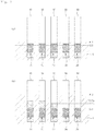
- Fig. 1 is a view illustrating a microfluidic device 1 for detecting target gene according to one embodiment of the present invention.
- the microfluidic device 1 for detecting target genes according to one embodiment of the present invention comprises a plurality of capillary tubes 10 and microbead packings 30.
- the plurality of capillary tubes 10 are configured to have a size such that sample solution 5 is able to flow into the capillary tube by capillarity phenomenon.
- sample solution 5 is able to flow into the capillary tube by capillarity phenomenon.
- six capillary tubes are arranged to be adjacent to each other, but the arrangement of the tubes is not limited thereto.
- the plurality of capillary tubes 10 are configured such that one end portion of the tube, i.e., a lower part of the tube as shown in Fig. 1 , is immersed in a sample container 3 which contains the sample solution 5, and the sample solution 5 flows into the tube through an inlet at the lower side of the tube by capillarity phenomenon and flows upwards.
- Microbead packing 30 is arranged in each capillary tube 10 on a flow path of the sample solution 5.
- the microbead packing 30 is manufactured separately from the microfluidic device 1 and then is inserted into the capillary tube 10 when the microfluidic device is manufactured.
- microbead packing 30 may comprise a packing tube 31, a plurality of microbeads 32 and probe linkers 33, as shown in Fig. 1 .
- the packing tube 31 is arranged on a flow path of the sample solution 5, i.e., in the capillary tube 10, to constitute some of the flow path of the sample solution 5. Also, the plurality of microbeads 32 contained in the packing tube 31 are in close and tight contact with each other and there are voids between the microbeads which are in close and tight contact with each other.
- a diameter of the microbead 32 depends on the type of the target gene and the size of the void varies according to a diameter of the target gene.
- the size of the void is set to make the target gene pass through the void and the size of the void can be adjusted by adjusting the size of the microbeads 32.
- the diameter of the microbead 32 is determined according to the type of the target gene within the range of 0.1 ⁇ m to 100 ⁇ m.
- the microbead packing 30 may comprise mesh 142 (see the embodiment in Fig. 4 ) which are arranged respectively at both ends of the packing tube 31.
- the inner diameter of the mesh 142 has a size by which the mircobead 32 is not discharged and the flow of the sample solution 5 is not disturbed.
- the probe linker 33 is formed on a surface of each microbead 32. Also, the probe linker 33 is configured such that amplification by the complementary bond with the target gene in the sample solution 5 is carried out, thereby detecting the target gene.
- the probe linker 33 comprises constituents disclosed in a paper 'DhITACT: DNA Hydrogel Formation by Isothermal Amplification of Complementary Target in Fluidic Channels (June 17, 2015, Advanced Materials, Volume 27, Issue 23, Pages 3513-3517)' published in 2015 by Ho Yeon Lee , et al. That is, for example, the probe linker 33 comprises a coating part, a primer, and a template.
- the coating part is coated on the surface of the microbead 32 and is formed of material to which the primer is attached and fixed.
- examples of the coating part may include one or more selected from a group of 5-hydroxydopamine hydrochloric acid, norepinephrine, epinephrine, pyrogallolamine, DOPA(3,4-Dihydroxyphenylalanine), catechin, tannins, pyrogallol, pyrocatechol, heparin-catechol, chitosan-catechol, poly(ethylene glycol)-catechol, poyl(ethyleneimine)-catechol, poly(methylmethacrylate)-catechol, hyaluronic acid-catechol, polylysine-catechol, and polylysine, etc.
- the primer is fixed at the coating part and the template is complementarily bonded to the primer.
- the template may comprises a first bonding part which is complementarily bonded to the target gene, a second bonding part which is complementarily bonded to the primer, and a third bonding part which is complementary in the template to form a shape of dumbbell. Further, the first bonding part is divided and formed at both ends of the template and the second bonding part is formed between the third bonding parts which are divided.
- examples of the primer may include one or more selected from a group consisting of thiol, amine, hydroxyl, carboxyl, isothiocyanate, NHS ester, aldehyde, epoxide, Carbonate, HOBtester, Glutaraldehyde, carbamate, imidazole carbamate, maleimide, aziridine, sulfone, vinylsulfone, hydrazine, phenyl azide, benzophenone, anthraquinone, and Diene groups, wherein a terminal is modified.
- the target gene is bonded to the probe linker 33 of the embodiment and is amplified and the amplified target gene is to form hydrogel. Detailed explanation will be omitted since it is disclosed in the above paper.
- an amplification by a complementary bonding of a target gene to a probe linker 33 formed on the surface of each microbead 32 generates a hydrogel, thereby blocking the void between the microbeads 32 and reducing the size of the void.
- the blocking of the void and the reduction of void size will be a resistance and in turn will prevent arise of the sample solution 5 due to capillary phenomenon or reduce the speed of the rise, thereby detecting a target gene.
- a method of detecting a target gene using the microfluidic device 1 according to the above embodiment will be described.
- the sample solution 5 is poured into the sample container 3.
- an initial quantity (WL1) of the sample solution 5 injected into the sample container 3 will be set to make the sample solution 5 reach the microbead packing 30 through the capillary tube 10 by capillary phenomenon (see CL1).
- the target gene in the sample solution 5 passing through the microbead packing 30 is amplified by the complementary bonding with the probe linker 33 of the microbead packing 30 and in turn, the target gene becomes hydrogel, thereby blocking the void between the microbeads 32 and reducing the size of the void.
- probe linkers 33 of each microbead packing 30 are provided to detect different target genes, only the void of the microbead packing 30 having the corresponding target gene will be blocked or a size of the void of the microbead packing 30 having the corresponding target gene will be reduced.
- the sample solution 5 is further supplied into the sample container 3 (see WL2), the sample solution 5 is supposed to flow upwards through the capillary tube 10.
- the sample solution 5 cannot flow to reach the opposite side of the microbead packing 30 by the amplification of the target gene, the presence of the corresponding target gene can be identified.
- the capillary tube 10 is immersed in the sample solution, and then, the capillary tube 10 is immersed deeper in the sample solution after a period of certain time, for example, time for which target gene can be amplified enough.
- a period of certain time for example, time for which target gene can be amplified enough.
- the color of the sample solution can be controlled.
- a paper whose color changes when it is wet is arranged at the upper part of the microbead packing 30 in the capillary tube 10.
- microfluidic device 100 for detecting target gene according to another embodiment will be described in detail.
- the microfluidic device 100 for detecting target gene may comprise a microchannel 130 and a microbead packing 140. Also, the microfluidic device 100 according to the embodiment may comprise a negative pressure chamber 120.
- the sample chamber 110 is arranged at one side of the microfluidic device 100 and contains sample solution.
- the microchannel 130 is in fluid communication with the sample chamber 110, and the sample solution contained in the sample chamber 110 flows through the microchannel 130.
- the microbead packing 140 is arranged on a flow path of the sample solution.
- the microbead packing is manufactured separately from the microfluidic device 100 and then is installed in the microchannel 130 when the microfluidic device 100 is manufactured.
- the upper substrate is attached to the base substrate in a state that the microbead packing 140 was inserted into the microchannel 130 of the upper substrate.
- the microbead packing 140 may comprise a packing tube 145, a plurality of microbeads 141 and probe linkers 143.
- the microbead packing 140 corresponds to that of the embodiment in Fig. 1 and detailed explanation thereof is omitted.
- the microbead packing 140 according to the embodiment may comprise meshes 142 which are arranged on both ends of the packing tube 145 respectively to prevent the loss of the microbeads 141.
- the size of the inner diameter of the mesh 142 is set to prevent the microbeads 141 from being discharged and not to disturb the flow of the sample solution.
- an amplification by a complementary bonding of a target gene to probe linkers133 formed on the surface of each microbead141 generates a hydrogel, thereby blocking the void 144 between the microbeads 141 and reducing the size of the void 144, thereby causing changes of a final travel distance by which the sample solution flows through the microchannel 130, time taken to reach the final travel distance, and a flow rate of the sample. Further, it is possible to detect the target gene by using at least one of the final travel distance, the travel time and the flow rate.
- the negative-pressure chamber 120 is arranged on the opposite side of the sample chamber 110 and is in fluid communication with the microchannel 130. Negative pressure from outside is applied by the negative-pressure chamber 120 such that sample solution flows through the microchannel 130.
- a plurality of microbeads 141 constitute the microbead packing 140, and probe linkers 143 formed on the microbeads 141 bond with the target gene. Then, the target gene is amplified and hydrogel is generated during the amplification and blocks the void 144 or reduces the size of the void 144, thereby causing the changes of the final travel distance, the travel time, the flow rate and/or pressure, whose detection makes it possible to identify the presence of the target gene.
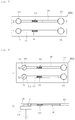
- Fig. 5 shows a microfluidic device 100a according to yet another embodiment of the present invention.
- the microfluidic device 100a according to the yet another embodiment may comprise a plurality of sample chambers 110, a plurality of microchannels 130, and a plurality of microbead packings 140.
- the sample chamber 110 and the microchannel 130 are connected to each other by one and one to form a flow path of the sample solution and a plurality of flow paths are arranged in parallel.
- two sample chambers 110 and two microchannels 130 are arranged in parallel to form two flow paths.
- the microbead packings 140 are arranged respectively in each microchannel 130.
- the microbeads 141 contained in one of the microbead packings 140 do not have probe linkers 143.
- the microbeads 141 of one of microbead packings 140 have probe linkers 143 and the microbeads 141 of the other of the microbead packings 140 do not have probe linkers 143.
- the same sample solution is contained in each sample chamber 110 and then the sample solution flows.
- the microbead packing 140 has the probe linkers, the bonding and the amplification of the target gene as described above cause the microbead packing to be blocked or cause the size of the void 144 to be reduced, thereby the flow of the sample solution being restricted.
- the microbead packing 140 has no probe linkers 143, the sample solution flowing through the microbead packing 140 flows without restriction.
- the final travel distance by which the sample solution which passed through the microbead packing 140 has traveled until the sample solution is stopped by the blocking of the microbead packing 140 is measured and the travel time thereof is measured, and then the final travel distance and time thereof are compared with those of the microbead packing 140 having no probe linkers 143, thereby it is possible to quantify an initial concentration of the target gene.
- each flow path is provided with a negative pressure chamber 120.
- an end of each microchannel 130 is connected to one negative pressure chamber 120, and negative pressure is applied for the flow of the sample solution by one negative pressure chamber 120.
- microbeads 141 of each microbead packing 140 may have different probe linkers 143, respectively so as to bond with different target genes. That is, since each probe linker 143 bonds with different target genes to amplify target genes, it is possible to detect a plurality of target genes simultaneously, by using one microfluidic device 100.
- Fig. 6 shows a microfluidic device 100b according to yet another embodiment of the present invention.
- the embodiment as shown in Fig. 6 is a modification of the embodiment of Fig. 5 and for example, each sample chamber 110 is provided with a stirrer 151.
- the stirrer 151 is configured to rotate by a rotation of a magnet 152 arranged outside the microfluidic device 100.
- the stirrer By the stirrer, the sample solution contained in the sample chamber 110 is stirred and in turn, target genes in the sample solution is distributed widely, thereby facilitating the bonding and amplification in the microbead packing 140.
- Fig. 7 shows a microfluidic device 100c according to yet another embodiment of the present invention.
- a microchannel 130 of the microfluidic device 100c may comprise a first flow channel 131 which is connected to a sample chamber 110 and the first flow channel 131 branches off into a plurality of second flow channels 132a,132b,132c,132d,132e.
- microbead packings140a,140b,140c,140d,140e are arranged in the second flow channel 132a,132b,132c,132d,132e, respectively.
- each microbeadpackings140a,140b,140c,140d,140e may have different inner diameter.
- the probe linkers 143 formed in each microbead 141 may be configured to bond with the same target gene.
- microbeadpackings140a,140b,140c,140d,140e having small diameter of the microbead 141 may be blocked even when the concentration of target gene in the sample solution is low.
- the blocking of the microbeadpackings140a,140b,140c,140d,140e depends on the concentration of the target gene in the sample solution and in turn, the blocking of the microbead packings occurs according to the order of the diameter size of the microbead 141. Accordingly, it is possible to evaluate quantitatively the target gene in the sample solution, based on the diameter of the microbead 141 which generates the blocking lastly.
- a plurality of second flow channels 132a,132b,132c,132d,132e are connected to each negative pressure chamber 120a,120b,120c,120d,120e, respectively.
- ends of second flow channels 132a,132b,132c,132d,132e are merged to be connected to one negative pressure chamber.
- the present invention is applied to the field of detecting various pathogenic viruses by the detection of genes.
Landscapes
- Health & Medical Sciences (AREA)
- Chemical & Material Sciences (AREA)
- Life Sciences & Earth Sciences (AREA)
- Immunology (AREA)
- Engineering & Computer Science (AREA)
- Hematology (AREA)
- General Health & Medical Sciences (AREA)
- Analytical Chemistry (AREA)
- Molecular Biology (AREA)
- Urology & Nephrology (AREA)
- Biomedical Technology (AREA)
- Physics & Mathematics (AREA)
- Biochemistry (AREA)
- General Physics & Mathematics (AREA)
- Pathology (AREA)
- Biotechnology (AREA)
- Microbiology (AREA)
- Chemical Kinetics & Catalysis (AREA)
- Clinical Laboratory Science (AREA)
- Organic Chemistry (AREA)
- Medicinal Chemistry (AREA)
- Food Science & Technology (AREA)
- Cell Biology (AREA)
- Dispersion Chemistry (AREA)
- Wood Science & Technology (AREA)
- Zoology (AREA)
- Proteomics, Peptides & Aminoacids (AREA)
- Tropical Medicine & Parasitology (AREA)
- Virology (AREA)
- Bioinformatics & Cheminformatics (AREA)
- General Engineering & Computer Science (AREA)
- Genetics & Genomics (AREA)
- Biophysics (AREA)
- Fluid Mechanics (AREA)
- Apparatus Associated With Microorganisms And Enzymes (AREA)
- Measuring Or Testing Involving Enzymes Or Micro-Organisms (AREA)
- Investigating Or Analysing Biological Materials (AREA)
- Automatic Analysis And Handling Materials Therefor (AREA)
Abstract
Description
- The present invention relates to a microfluidic device for detecting a target gene and in particular, to a microfluidic device for detecting a target gene using phenomenon in which a target gene is amplified such that a void formed by microbeads is blocked or a size of the void is reduced, for the detection of various pathogenic viruses by the target gene amplification.
- Efficient amplification of target nucleic acid is a very important factor for detection of nucleic acid as well as DNA sequencing, cloning, etc. There are various methods for amplifying nucleic acid such as PCR(polymerase chain reaction), LCR(ligase chain reaction), SSR(self-sustained sequence replication), NASBA(nucleic acid sequence based amplification), and SDA(strand displacement amplification), etc.
- Many of the above methods have disadvantages in that they have a relatively low accuracy of quantitative measurement and requires expensive devices and the disadvantages are particularly getting worse when it is needed to analyze more than one target simultaneously.
- To make up for such disadvantages, an isothermal amplification was invented and in particular, a RCA (rolling circle amplification) method has been paid much attention to. That is, several techniques such as PCR have been used for detecting DNA so far, but these methods are disadvantageous since they are time-consuming, are not efficient and require high cost and manpower.
- PCR method comprises a denaturation in which DNA is separated into single strand by heating DNA in reaction solution containing primer pairs, template, polymerase, and dNTP; an annealing in which a primer complementary to each separated DNA chain is bonded to a template by lowering temperature; and a polymerization in which new strands is polymerized by a polymerization reaction using polymerase by increasing temperature, and such an amplification increases DNA chain exponentially.
- However, PCR process should have experience the above steps and thus, it inevitably incurs temperature change. Therefore, devices for PCR must have a temperature controller and a heating means. If PCR is used for the amplification of target nucleic acid in a lab-on-a-chip (LOC), etc., a temperature controller and a heater for PCR reaction is further required besides detection devices for LOC, it is disadvantageous that devices are complex and cost for the devices is increasing.
- To solve the above disadvantage, several isothermal amplification methods have been suggested. LAMP (loop-mediated isothermal amplification) is one of the isothermal amplification methods and generates a multi-loop product having branches using 6 amplification primers. Such LAMP is not appropriate for an early diagnosis or a biosensor since an initial reverse transcriptase (RT) is used to detect a target RNA.
- RCA method was suggested as another isothermal amplification method. Advantageously, RCA method does not require a temperature change necessary for the PCR amplification as described above and thus, it is possible to amplify a target nucleic acid in a isothermal state. Therefore, it is possible to amplify without a temperature controller in a process requiring the amplification, thereby reducing a complexity of the device and costs.
- In a LRCA (linear rolling circle amplification) method, a target NDA sequence and an open circular probe are hybridized to form a complex and then an amplification target circle is generated by ligation, and thereafter, primer sequence and DNA polymerase are introduced. Amplification target circle forms a template in which a new DNA is formed, elongation is carried out from primer to be extended into continuous sequence of repeated sequence complementary to an amplification target circle, thereby generating thousands of copies of nucleic acid per an hour.
- As a further developed method, ERCA(exponential RCA) method was developed. In the ERCA method, a new amplification center is provided using an additional primer sequence which bonds to a replicated sequence complementary to an amplification target circle, thereby the amplification is increased exponentially. In the ERCA method, a strand displacement method is continued, but it is limited to a method in which an initial single strand RCA product is used as a template of another DNA synthesis by using a separate single strand primer attached to the product without additional RCA.
- Another method using molecular padlock probe(MPP) and rolling circle amplification (RCA) is disclosed (C. Larsson et al,, Nat. Methods 2004, 1, 227). This method has several advantages and is characterized in that complementary nucleic acid is amplified in a circular MPP by the identification of target nucleic acid sequence and a high specificity. In particular, sensitivity is improved by direct coupling of RCA product without further purification. RCA reaction can be started on the surface by fixing target nucleic acid probes to a surface of material such as gold, quartz, etc. through simple chemical surface treatment.
- Meanwhile, paper published by Ho Yeon Lee in 2015 'DhITACT: DNA Hydrogel Formation by Isothermal Amplification of Complementary Target in Fluidic Channels (June 17, 2015, Advanced Materials, Volume 27, Issue 23, Pages 3513-3517) discloses a technique in which RCA reaction surface is provided on the bottom of the microchannel, then for two hours, a reaction with sample solution is carried out, and a single strand of DNA is elongated and self-assembly in the form of multiple dumbbells occurs, thereby DNA becomes to form a hydrogel shape and a flow in the corresponding channel is excluded.
- However, techniques disclosed in the paper of Ho Yeon Lee have a disadvantage that it takes more than two hours to take a test, since RCA reaction surface should be formed on the bottom surface of the microchannel and then a tester has to wait until the entire microchannel is blocked by the amplification at the RCA reaction surface.
- Accordingly, the present invention is provided to solve the above problems and an object of the present invention is to provide a microfluidic device for detection target gene which can reduce the detection time significantly, wherein for the detection of various pathogenic viruses by the detection of genes, the target gene is detected by phenomenon in which voids generated by the microbeads are blocked or a size of the voids is reduced by the amplification of the target gene.
- Another object of the present invention is to provide a microfluidic device for detecting the target gene, wherein it is possible to quantitatively analyze the target gene according to the detection based on various methods.
- The above object is accomplished by a microfluidic device for detecting a target gene, comprising: a plurality of capillary tubes which are partially immersed in a sample container containing sample solution and in which the sample solution flows by capillary phenomenon, and microbead packings arranged at one part in each capillary tube to be arranged on a flow path of the sample solution, wherein each of the microbead packings comprises: a packing tube arranged at the capillary tube so as to partially constitute the flow path of the sample solution, a plurality of microbeads contained in the packing tube and being in close contact with each other to form voids between the microbeads, and probe linkers formed on a surface of each microbead, wherein the probe linkers are configured to amplify a target gene in the sample solution by complementary bonding with the target gene, thereby detecting the target gene, according to the present invention.
- Here, an initial volume of the sample solution contained in the sample container may be set to make the sample solution reach the microbead packing through the capillary tube by capillary phenomenon, wherein the void may be blocked or a size of the void may be reduced by the amplification of the target gene induced by the complementary bonding between the target gene in the sample solution which reached the microbead packing and the probe linker, and wherein when the sample solution is further introduced into the sample container, the target gene may be detected based on at least one of whether the sample solution flows to the opposite side of the microbead packing or a final travel distance of the sample solution.
- Also, the probe linkers of each microbead packing may be configured to detect different target genes.
- Meanwhile, the above object may be accomplished by a microfluidic device for detecting a target gene, comprising: a sample chamber containing sample solution; a microchannel which is connected to the sample chamber and through which the sample solution flows; and a microbead packing arranged on a flow path of the sample solution in the microchannel; wherein the microbead packing comprises: a packing tube arranged at a microchannel so as to partially constitute the flow path of the sample solution, a plurality of microbeads contained in the packing tube and being in close contact with each other to form voids between the microbeads, and probe linkers formed on a surface of each microbead, wherein the probe linkers are configured to amplify a target gene in the sample solution by complementary bonding with the target gene, thereby detecting the target gene, according to another embodiment of the present invention.
- Here, the void may be blocked or a size of the void may be reduced by the amplification of the target gene induced by the complementary bonding between the target gene and the probe linker, whereby a final travel distance of the sample solution, time taken for the final travel distance, and a flow rate of the sample solution are changed, and wherein the target gene may be detected by one of the final travel distance, the time taken for the final travel distance and the flow rate.
- Also, the microfluidic device may further comprise a negative pressure chamber arranged on the opposite side of the sample chamber to be in fluid communication with the microchannel, the negative chamber applying negative pressure from outside to make the sample solution flow through the microchannel, wherein the void may be blocked or a size of the void may be reduced by the amplification of the target gene induced by the complementary bonding between the target gene and the probe linker, whereby the target gene is detected according to a change of the negative pressure applied by the negative pressure chamber.
- Also, a diameter of the microbead may be set to have a size such that the target gene is able to pass through the void according to a type of the target gene within the range of 0.1µm to 100µm.
- Also, the microbead packing may comprise meshes arranged respectively at both ends of the packing tube to prevent loss of the microbeads.
- Also, the sample chamber, the microchannel and the microbead packing may be provided in plural, respectively to be arranged in parallel and the microbeads contained in one of the microbead packings do not have the probe linkers.
- Also, the sample chamber, the microchannel and the microbead packing may be provided in plural, respectively to be arranged in parallel and the probe linkers of each microbead packing are configured to detect different target genes.
- Also, the microchannel may comprise: a first flow channel connected to the sample chamber and a plurality of second flow channels diverged from the first flow channel, wherein the microbead packing may be provided in plural to be arranged in each of the second flow channels, wherein the microbeads contained in each microbead packing may have a different diameter.
- Also, the probe linker may comprise a coating part coated on a surface of the microbead, a primer attached to the coating part, and a template which complementarily bonds to the primer, wherein the template may comprise a first bonding part which complementarily bonds to the target gene, a second bonding part which complementarily bonds to the primer, and a third bonding part which is complementary in the template to form a dumbbell, and wherein the first bonding part is divided and formed at both ends of the template and the second bonding part is formed between the third bonding part which are divided.
- Also, the coating part may include one or more selected from a group consisting of 5-hydroxydopamine hydrochloric acid, norepinephrine, epinephrine, pyrogallolamine, DOPA(3,4-Dihydroxyphenylalanine), catechin, tannins, pyrogallol, pyrocatechol, heparin-catechol, chitosan-catechol, poly(ethylene glycol)-catechol, poyl(ethyleneimine)-catechol, poly(methylmethacrylate)-catechol, hyaluronic acid-catechol, polylysine-catechol, and polylysine.
- Also, the primer may include one or more selected from a group consisting of thiol, amine, hydroxyl, carboxyl, isothiocyanate, NHS ester, aldehyde, epoxide, Carbonate, HOBtester, Glutaraldehyde, carbamate, imidazole carbamate, maleimide, aziridine, sulfone, vinylsulfone, hydrazine, phenyl azide, benzophenone, anthraquinone, and Diene groups, and wherein a terminal of the primer is modified.
- By the above arrangement, for the detection of various pathogenic viruses by the detection of genes, the target gene is detected by phenomenon in which voids generated by the microbeads are blocked or a size of the voids is reduced by the amplification of the target gene, thereby making it possible to provide a microfluidic device for detection target gene which can reduce the detection time significantly.
- Also, it is possible to quantitatively analyze the target gene according to the detection based on various methods.
-
-
Fig. 1 is a view illustrating a microfluidic device for detecting a target gene according to one embodiment of the present invention. -
Fig. 2 is a view illustrating a method of detecting a target gene using the microfluidic device for detecting a target gene according to the embodiment. -
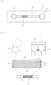
Fig. 3 is a view illustrating a microfluidic device for detecting a target gene according to one embodiment of the present invention. -
Fig. 4 is a view illustrating a microbead packing of a microfluidic device for detecting a target gene according to the embodiment of the present invention. -
Figs. 5 to 7 show a microfluidic device for detecting a target gene according to yet another embodiment of the present invention. -
- 1,100,100a,100b,100c: microfluidic device
- 10: capillary tube 110: sample chamber
- 120,120a,120b,120c,120d,120e: negative pressure chamber
- 130: microchannel 131: first flow channel
- 132a,132b,132c,132d,132e: second flow channel
- 30,140,140a,140b,140c,140d,140e: microbead packing
- 32,141: microbead 142: mesh
- 33,143: probe liner 144: void
- 31,145: packing tube 151: stirrer
- 152: magnet
- The present invention relates to a microfluidic device for detecting a target gene and is characterized in that it comprises: a plurality of capillary tubes which are partially immersed in a sample container containing sample solution and in which the sample solution flows by capillary phenomenon, and microbead packings arranged at one part in each capillary tube to be arranged on a flow path of the sample solution, wherein each of the microbead packings comprises: a packing tube arranged at the capillary tube so as to partially constitute the flow path of the sample solution, a plurality of microbeads contained in the packing tube and being in close contact with each other to form voids between the microbeads, and probe linkers formed on a surface of each microbead, wherein the probe linkers are configured to amplify a target gene in the sample solution by complementary bonding with the target gene, thereby detecting the target gene, according to the present invention.
- Hereinafter, embodiments of the present invention will be described in detail with reference to the accompanying drawings.
-
Fig. 1 is a view illustrating a microfluidic device 1 for detecting target gene according to one embodiment of the present invention. Referring toFig. 1 , the microfluidic device 1 for detecting target genes according to one embodiment of the present invention comprises a plurality ofcapillary tubes 10 andmicrobead packings 30. - The plurality of
capillary tubes 10 are configured to have a size such thatsample solution 5 is able to flow into the capillary tube by capillarity phenomenon. In the embodiment, for example, as shown inFig. 1 , six capillary tubes are arranged to be adjacent to each other, but the arrangement of the tubes is not limited thereto. - The plurality of
capillary tubes 10 are configured such that one end portion of the tube, i.e., a lower part of the tube as shown inFig. 1 , is immersed in a sample container 3 which contains thesample solution 5, and thesample solution 5 flows into the tube through an inlet at the lower side of the tube by capillarity phenomenon and flows upwards. - Microbead packing 30 is arranged in each
capillary tube 10 on a flow path of thesample solution 5. Here, for example, the microbead packing 30 is manufactured separately from the microfluidic device 1 and then is inserted into thecapillary tube 10 when the microfluidic device is manufactured. - Meanwhile, the microbead packing 30 according to the embodiment may comprise a packing
tube 31, a plurality ofmicrobeads 32 andprobe linkers 33, as shown inFig. 1 . - The packing
tube 31 is arranged on a flow path of thesample solution 5, i.e., in thecapillary tube 10, to constitute some of the flow path of thesample solution 5. Also, the plurality ofmicrobeads 32 contained in the packingtube 31 are in close and tight contact with each other and there are voids between the microbeads which are in close and tight contact with each other. - Here, a diameter of the
microbead 32 depends on the type of the target gene and the size of the void varies according to a diameter of the target gene. In this regard, the size of the void is set to make the target gene pass through the void and the size of the void can be adjusted by adjusting the size of themicrobeads 32. In the embodiment, for example, the diameter of themicrobead 32 is determined according to the type of the target gene within the range of 0.1µm to 100µm. - Further, the microbead packing 30 according to the embodiment may comprise mesh 142 (see the embodiment in
Fig. 4 ) which are arranged respectively at both ends of the packingtube 31. Advantageously, the inner diameter of themesh 142 has a size by which themircobead 32 is not discharged and the flow of thesample solution 5 is not disturbed. Meanwhile, theprobe linker 33 is formed on a surface of eachmicrobead 32. Also, theprobe linker 33 is configured such that amplification by the complementary bond with the target gene in thesample solution 5 is carried out, thereby detecting the target gene. - In the embodiment, the
probe linker 33 comprises constituents disclosed in a paper 'DhITACT: DNA Hydrogel Formation by Isothermal Amplification of Complementary Target in Fluidic Channels (June 17, 2015, Advanced Materials, Volume 27, Issue 23, Pages 3513-3517)' published in 2015 by Ho Yeon Lee, et al. That is, for example, theprobe linker 33 comprises a coating part, a primer, and a template. - The coating part is coated on the surface of the
microbead 32 and is formed of material to which the primer is attached and fixed. As described in the above paper, examples of the coating part may include one or more selected from a group of 5-hydroxydopamine hydrochloric acid, norepinephrine, epinephrine, pyrogallolamine, DOPA(3,4-Dihydroxyphenylalanine), catechin, tannins, pyrogallol, pyrocatechol, heparin-catechol, chitosan-catechol, poly(ethylene glycol)-catechol, poyl(ethyleneimine)-catechol, poly(methylmethacrylate)-catechol, hyaluronic acid-catechol, polylysine-catechol, and polylysine, etc. - The primer is fixed at the coating part and the template is complementarily bonded to the primer. Here, the template may comprises a first bonding part which is complementarily bonded to the target gene, a second bonding part which is complementarily bonded to the primer, and a third bonding part which is complementary in the template to form a shape of dumbbell. Further, the first bonding part is divided and formed at both ends of the template and the second bonding part is formed between the third bonding parts which are divided.
- Here, examples of the primer may include one or more selected from a group consisting of thiol, amine, hydroxyl, carboxyl, isothiocyanate, NHS ester, aldehyde, epoxide, Carbonate, HOBtester, Glutaraldehyde, carbamate, imidazole carbamate, maleimide, aziridine, sulfone, vinylsulfone, hydrazine, phenyl azide, benzophenone, anthraquinone, and Diene groups, wherein a terminal is modified.
- With the above arrangement, the target gene is bonded to the
probe linker 33 of the embodiment and is amplified and the amplified target gene is to form hydrogel. Detailed explanation will be omitted since it is disclosed in the above paper. - As described above, an amplification by a complementary bonding of a target gene to a
probe linker 33 formed on the surface of eachmicrobead 32 generates a hydrogel, thereby blocking the void between themicrobeads 32 and reducing the size of the void. The blocking of the void and the reduction of void size will be a resistance and in turn will prevent arise of thesample solution 5 due to capillary phenomenon or reduce the speed of the rise, thereby detecting a target gene. - Referring to
Fig. 2 , a method of detecting a target gene using the microfluidic device 1 according to the above embodiment will be described. - First, as shown in
Fig. 2 (a) , thesample solution 5 is poured into the sample container 3. Here, an initial quantity (WL1) of thesample solution 5 injected into the sample container 3 will be set to make thesample solution 5 reach the microbead packing 30 through thecapillary tube 10 by capillary phenomenon (see CL1). - Here, the target gene in the
sample solution 5 passing through the microbead packing 30 is amplified by the complementary bonding with theprobe linker 33 of the microbead packing 30 and in turn, the target gene becomes hydrogel, thereby blocking the void between themicrobeads 32 and reducing the size of the void. - Here, in case that probe
linkers 33 of each microbead packing 30 are provided to detect different target genes, only the void of the microbead packing 30 having the corresponding target gene will be blocked or a size of the void of the microbead packing 30 having the corresponding target gene will be reduced. - Then, as shown in
Fig. 2 , when thesample solution 5 is further supplied into the sample container 3 (see WL2), thesample solution 5 is supposed to flow upwards through thecapillary tube 10. Here, if thesample solution 5 cannot flow to reach the opposite side of the microbead packing 30 by the amplification of the target gene, the presence of the corresponding target gene can be identified. - Referring to
Fig. 2 (b) , in the twocapillary tube 10 on the left, it can be seen that thesample solution 5 passed through the microbead packing 30 and rose (see CL2a) and this shows that thesample solution 5 has no target gene which bonds with theprobe linker 33 of the microbead packing 30. - On the contrary, in the two
capillary tube 10 on the right, it can be seen that thesample solution 5 did not pass through the microbead packing 30 since the microbead packing 30 is blocked and this shows that thesample solution 5 has target gene which bonds with theprobe linker 33 of the microbead packing 30. And, in the capillary tube on the center, it can be seen that thesample solution 5 has relatively small quantity of target gene since the void was not blocked completely or it takes time for the void to be blocked. - In the above embodiment, it was tested whether the void is blocked by adding sample solution. In an alternative method, the
capillary tube 10 is immersed in the sample solution, and then, thecapillary tube 10 is immersed deeper in the sample solution after a period of certain time, for example, time for which target gene can be amplified enough. By this, if thesample solution 5 flowing upwards through thecapillary tube 10 cannot flow to reach the opposite side of the microbead packing 30 due to the amplification of the target gene, it is possible to identify the presence of the target gene. - Here, in order to facilitate a visual identification as to whether the sample solution has moved to the upper part of the
capillary tube 10, the color of the sample solution can be controlled. For example, a paper whose color changes when it is wet is arranged at the upper part of the microbead packing 30 in thecapillary tube 10. By this arrangement, if color of the paper located in thecapillary tube 10 is changed when the paper is wet by the sample solution, it can be identified that there is no target gene in thecapillary tube 10. - Hereinafter, referring to
Figs. 3 and 4 , themicrofluidic device 100 for detecting target gene according to another embodiment will be described in detail. - Referring to
Figs. 3 and 4 , themicrofluidic device 100 for detecting target gene according to another embodiment (hereinafter referred to as 'microfluidic device 100') may comprise amicrochannel 130 and amicrobead packing 140. Also, themicrofluidic device 100 according to the embodiment may comprise anegative pressure chamber 120. - The
sample chamber 110 is arranged at one side of themicrofluidic device 100 and contains sample solution. Themicrochannel 130 is in fluid communication with thesample chamber 110, and the sample solution contained in thesample chamber 110 flows through themicrochannel 130. - The microbead packing 140 is arranged on a flow path of the sample solution. Here, the microbead packing is manufactured separately from the
microfluidic device 100 and then is installed in themicrochannel 130 when themicrofluidic device 100 is manufactured. For example, when an upper substrate having asample chamber 110, amicrochannel 130, and a fluid-pressure chamber is attached to a transparent base substrate in an upward and downward direction in order to manufacture themicrofluidic device 100, the upper substrate is attached to the base substrate in a state that the microbead packing 140 was inserted into themicrochannel 130 of the upper substrate. - Meanwhile, as shown in
Fig. 4 , the microbead packing 140 according to the embodiment of the present invention may comprise apacking tube 145, a plurality ofmicrobeads 141 and probelinkers 143. Here, the microbead packing 140 corresponds to that of the embodiment inFig. 1 and detailed explanation thereof is omitted. As shown inFig. 4 , the microbead packing 140 according to the embodiment may comprisemeshes 142 which are arranged on both ends of thepacking tube 145 respectively to prevent the loss of themicrobeads 141. Advantageously, the size of the inner diameter of themesh 142 is set to prevent themicrobeads 141 from being discharged and not to disturb the flow of the sample solution. - Here, an amplification by a complementary bonding of a target gene to probe linkers133 formed on the surface of each microbead141 generates a hydrogel, thereby blocking the void 144 between the
microbeads 141 and reducing the size of the void 144, thereby causing changes of a final travel distance by which the sample solution flows through themicrochannel 130, time taken to reach the final travel distance, and a flow rate of the sample. Further, it is possible to detect the target gene by using at least one of the final travel distance, the travel time and the flow rate. - Referring back to
Fig. 3 , the negative-pressure chamber 120 is arranged on the opposite side of thesample chamber 110 and is in fluid communication with themicrochannel 130. Negative pressure from outside is applied by the negative-pressure chamber 120 such that sample solution flows through themicrochannel 130. - Here, if the void 144 is blocked or the size of the void 144 is reduced by the amplification due to the complementary bonding of the target gene to the
probe linker 143, pressure which has been being constantly applied by the negative-pressure chamber 120 will change, thereby it being possible to identify the presence of the target gene. - According to the above embodiment, a plurality of
microbeads 141 constitute the microbead packing 140, and probelinkers 143 formed on themicrobeads 141 bond with the target gene. Then, the target gene is amplified and hydrogel is generated during the amplification and blocks the void 144 or reduces the size of the void 144, thereby causing the changes of the final travel distance, the travel time, the flow rate and/or pressure, whose detection makes it possible to identify the presence of the target gene. - Also, it is possible to make a test by blocking or clogging the void 144 formed by the
microbeads 141 instead of blocking the entire of themicrochannel 130 as disclosed in the paper, thereby making it possible to reduce test time significantly. Further, it is possible to increase a reaction area by formingprobe linkers 143 on the surface of eachmicrobeads 141, instead of forming a reaction area on the bottom surface only as disclosed in the above paper, thereby making it possible to reduce test time significantly. - It is possible to detect the presence of the target gene by clogging phenomenon of the void, and it is also possible to evaluate quantitatively the target gene by using the change of the final travel distance, the travel time, the flow rate or the pressure, etc. For example, if there are a lot of target genes, the probability of reaction increases and in turn, the
void 144 is blocked more quickly and the final travel distance is reduced, which can be quantified based on a statistical method, thereby making it possible to evaluate quantitatively the target gene. -
Fig. 5 shows amicrofluidic device 100a according to yet another embodiment of the present invention. As shown inFig. 5 , themicrofluidic device 100a according to the yet another embodiment may comprise a plurality ofsample chambers 110, a plurality ofmicrochannels 130, and a plurality ofmicrobead packings 140. Here, thesample chamber 110 and themicrochannel 130 are connected to each other by one and one to form a flow path of the sample solution and a plurality of flow paths are arranged in parallel. InFig. 5 , for example, twosample chambers 110 and twomicrochannels 130 are arranged in parallel to form two flow paths. Themicrobead packings 140 are arranged respectively in eachmicrochannel 130. - Here, the
microbeads 141 contained in one of themicrobead packings 140 do not haveprobe linkers 143. Referring toFig. 5 , as described above, for example, themicrobeads 141 of one ofmicrobead packings 140 haveprobe linkers 143 and themicrobeads 141 of the other of themicrobead packings 140 do not haveprobe linkers 143. - In the example, the same sample solution is contained in each
sample chamber 110 and then the sample solution flows. Here, if the microbead packing 140 has the probe linkers, the bonding and the amplification of the target gene as described above cause the microbead packing to be blocked or cause the size of the void 144 to be reduced, thereby the flow of the sample solution being restricted. On the contrary, if the microbead packing 140 has noprobe linkers 143, the sample solution flowing through the microbead packing 140 flows without restriction. - Further, in case that the microbead packing 140 has the
probe linkers 143, the final travel distance by which the sample solution which passed through the microbead packing 140 has traveled until the sample solution is stopped by the blocking of the microbead packing 140 is measured and the travel time thereof is measured, and then the final travel distance and time thereof are compared with those of the microbead packing 140 having noprobe linkers 143, thereby it is possible to quantify an initial concentration of the target gene. - Here, in the embodiment of
Fig. 5 , for example, each flow path is provided with anegative pressure chamber 120. Besides, of course, it should be noted that an end of each microchannel 130 is connected to onenegative pressure chamber 120, and negative pressure is applied for the flow of the sample solution by onenegative pressure chamber 120. - Further, in the embodiment of
Fig. 5 ,microbeads 141 of each microbead packing 140 may havedifferent probe linkers 143, respectively so as to bond with different target genes. That is, since eachprobe linker 143 bonds with different target genes to amplify target genes, it is possible to detect a plurality of target genes simultaneously, by using onemicrofluidic device 100. -
Fig. 6 shows amicrofluidic device 100b according to yet another embodiment of the present invention. The embodiment as shown inFig. 6 is a modification of the embodiment ofFig. 5 and for example, eachsample chamber 110 is provided with astirrer 151. - Here, the
stirrer 151 is configured to rotate by a rotation of amagnet 152 arranged outside themicrofluidic device 100. By the stirrer, the sample solution contained in thesample chamber 110 is stirred and in turn, target genes in the sample solution is distributed widely, thereby facilitating the bonding and amplification in the microbead packing 140. -
Fig. 7 shows amicrofluidic device 100c according to yet another embodiment of the present invention. Referring toFig. 7 , amicrochannel 130 of themicrofluidic device 100c according to yet may comprise afirst flow channel 131 which is connected to asample chamber 110 and thefirst flow channel 131 branches off into a plurality ofsecond flow channels second flow channel - Here, the
microbeads 141 contained in each microbeadpackings140a,140b,140c,140d,140e may have different inner diameter. The probe linkers 143 formed in eachmicrobead 141 may be configured to bond with the same target gene. - In the above arrangement, microbeadpackings140a,140b,140c,140d,140e having small diameter of the
microbead 141 may be blocked even when the concentration of target gene in the sample solution is low. The blocking of the microbeadpackings140a,140b,140c,140d,140edepends on the concentration of the target gene in the sample solution and in turn, the blocking of the microbead packings occurs according to the order of the diameter size of themicrobead 141. Accordingly, it is possible to evaluate quantitatively the target gene in the sample solution, based on the diameter of themicrobead 141 which generates the blocking lastly. - Here, in the embodiment of
Fig. 7 , for example, a plurality ofsecond flow channels negative pressure chamber second flow channels - Although several embodiments of the present invention are illustrated and explained above, it is obvious that the embodiments can be easily devised by those skilled in the technical idea of the present invention within the scope of the technical idea or spirit included in the specification of the present invention. The scope of the present invention will be determined by attached claims and their equivalents.
- The present invention is applied to the field of detecting various pathogenic viruses by the detection of genes.
Claims (14)
- A microfluidic device for detecting a target gene, comprising:a plurality of capillary tubes which are partially immersed in a sample container containing sample solution and in which the sample solution flows by capillary phenomenon, andmicrobead packings arranged atone part in each capillary tube to be arranged on a flow path of the sample solution,wherein each of the microbead packings comprises:a packing tube arranged at the capillary tube so as to partially constitute the flow path of the sample solution,a plurality of microbeads contained in the packing tube and being in close contact with each other to form voids between the microbeads, andprobe linkers formed on a surface of each microbead,wherein the probe linkers are configured to amplify a target gene in the sample solution by complementary bonding with the target gene, thereby detecting the target gene.
- The microfluidic device for detecting a target gene according to Claim 1, wherein an initial volume of the sample solution contained in the sample container is set to make the sample solution reach the microbead packing through the capillary tube by capillary phenomenon,
wherein the void is blocked or a size of the void is reduced by the amplification of the target gene induced by the complementary bonding between the target gene in the sample solution which reached the microbead packing and the probe linker, and
wherein when the sample solution is further introduced into the sample container, the target gene is detected based on at least one of whether the sample solution flows to the opposite side of the microbead packing or a final travel distance of the sample solution. - The microfluidic device for detecting a target gene according to Claim 1, wherein the probe linkers of each microbead packing are configured to detect different target genes.
- A microfluidic device for detecting a target gene, comprising:a sample chamber containing sample solution;a microchannel which is connected to the sample chamber and through which the sample solution flows; anda microbead packing arranged on a flow path of the sample solution in the microchannel;wherein the microbead packing comprises:a packing tube arranged at a microchannel so as to partially constitute the flow path of the sample solution,a plurality of microbeads contained in the packing tube and being in close contact with each other to form voids between the microbeads, andprobe linkers formed on a surface of each microbead,wherein the probe linkers are configured to amplify a target gene in the sample solution by complementary bonding with the target gene, thereby detecting the target gene.
- The microfluidic device for detecting a target gene according to Claim 4, wherein the void is blocked or a size of the void is reduced by the amplification of the target gene induced by the complementary bonding between the target gene and the probe linker, whereby a final travel distance of the sample solution, time taken for the final travel distance, and a flow rate of the sample solution are changed, and wherein the target gene is detected by one of the final travel distance, the time taken for the final travel distance and the flow rate.
- The microfluidic device for detecting a target gene according to Claim 4, further comprising a negative pressure chamber arranged on the opposite side of the sample chamber to be in fluid communication with the microchannel, the negative chamber applying negative pressure from outside to make the sample solution flow through the microchannel,
wherein the void is blocked or a size of the void is reduced by the amplification of the target gene induced by the complementary bonding between the target gene and the probe linker, whereby the target gene is detected according to a change of the negative pressure applied by the negative pressure chamber. - The microfluidic device for detecting a target gene according to Claim 4, wherein the sample chamber, the microchannel and the microbead packing are provided in plural, respectively to be arranged in parallel and the microbeads contained in one of the microbead packings do not have the probe linkers.
- The microfluidic device for detecting a target gene according to Claim 4, wherein the sample chamber, the microchannel and the microbead packing are provided in plural, respectively to be arranged in parallel and the probe linkers of each microbead packing are configured to detect different target genes.
- The microfluidic device for detecting a target gene according to Claim 4, wherein the microchannel comprises:a first flow channel connected to the sample chamber anda plurality of second flow channels diverged from the first flow channel,wherein the microbead packing is provided in plural to be arranged in each of the second flow channels,wherein the microbeads contained in each microbead packing have a different diameter.
- The microfluidic device for detecting a target gene according to claim 1 or Claim 4, wherein a diameter of the microbead is set to have a size such that the target gene is able to pass through the void according to a type of the target gene within the range of 0.1µm to 100µm.
- The microfluidic device for detecting a target gene according to claim 1 or Claim 4, wherein the microbead packing comprises meshes arranged respectively at both ends of the packing tube to prevent loss of the microbeads.
- The microfluidic device for detecting a target gene according to claim 1 or Claim 4,
wherein the probe linker comprises a coating part coated on a surface of the microbead, a primer attached to the coating part, and a template which complementarily bonds to the primer,
wherein the template comprises a first bonding part which complementarily bonds to the target gene, a second bonding part which complementarily bonds to the primer, and a third bonding part which is complementary in the template to form a dumbbell, and wherein the first bonding part is divided and formed at both ends of the template and the second bonding part is formed between the third bonding part which are divided. - The microfluidic device for detecting a target gene according to Claim 12, wherein the coating part includesone or more selected from a group consisting of 5-hydroxydopamine hydrochloric acid, norepinephrine, epinephrine, pyrogallolamine, DOPA(3,4-Dihydroxyphenylalanine), catechin, tannins, pyrogallol, pyrocatechol, heparin-catechol, chitosan-catechol, poly(ethylene glycol)-catechol, poyl(ethyleneimine)-catechol, poly(methylmethacrylate)-catechol, hyaluronic acid-catechol, polylysine-catechol, and polylysine.
- The microfluidic device for detecting a target gene according to Claim 12, wherein the primer includes one or more selected from a group consisting of thiol, amine, hydroxyl, carboxyl, isothiocyanate, NHS ester, aldehyde, epoxide, Carbonate, HOBtester, Glutaraldehyde, carbamate, imidazole carbamate, maleimide, aziridine, sulfone, vinylsulfone, hydrazine, phenyl azide, benzophenone, anthraquinone, and Diene groups, and wherein a terminal of the primer is modified.
Applications Claiming Priority (2)
| Application Number | Priority Date | Filing Date | Title |
|---|---|---|---|
| KR1020160035182A KR101799192B1 (en) | 2016-03-24 | 2016-03-24 | Micro-fluidic apparatus for detecting target gene |
| PCT/KR2017/001694 WO2017164514A1 (en) | 2016-03-24 | 2017-02-16 | Microfluidic device for detecting target gene |
Publications (3)
| Publication Number | Publication Date |
|---|---|
| EP3434369A1 true EP3434369A1 (en) | 2019-01-30 |
| EP3434369A4 EP3434369A4 (en) | 2019-11-06 |
| EP3434369B1 EP3434369B1 (en) | 2024-10-23 |
Family
ID=59900583
Family Applications (1)
| Application Number | Title | Priority Date | Filing Date |
|---|---|---|---|
| EP17770485.5A Active EP3434369B1 (en) | 2016-03-24 | 2017-02-16 | Microfluidic device for detecting target gene |
Country Status (6)
| Country | Link |
|---|---|
| US (1) | US11204348B2 (en) |
| EP (1) | EP3434369B1 (en) |
| JP (1) | JP6719582B2 (en) |
| KR (1) | KR101799192B1 (en) |
| CN (1) | CN108883412B (en) |
| WO (1) | WO2017164514A1 (en) |
Cited By (1)
| Publication number | Priority date | Publication date | Assignee | Title |
|---|---|---|---|---|
| AT525192A1 (en) * | 2021-06-15 | 2023-01-15 | Genspeed Biotech Gmbh | MICROFLUIDIC CHIP |
Families Citing this family (6)
| Publication number | Priority date | Publication date | Assignee | Title |
|---|---|---|---|---|
| US20200011795A1 (en) | 2017-02-28 | 2020-01-09 | The Regents Of The University Of California | Optofluidic analyte detection systems using multi-mode interference waveguides |
| EP3692361A4 (en) * | 2017-10-02 | 2021-06-09 | The Regents of The University of California | SYSTEMS AND METHODS FOR RELEASING TARGET MOLECULES IN A NANOPORE |
| KR102433694B1 (en) * | 2020-07-24 | 2022-08-19 | 고려대학교 산학협력단 | Micro-fluidic apparatus for detecting nucleic acid |
| CN113652341B (en) * | 2020-07-29 | 2025-02-14 | 哈尔滨工业大学 | A microfluidic visual on-site rapid inspection device and detection method based on nucleic acid isothermal amplification reaction blocking flow |
| KR102579071B1 (en) | 2021-02-18 | 2023-09-15 | 고려대학교 산학협력단 | Micro-fluidic apparatus for detecting nucleic acid with pore structure |
| CN114854026B (en) * | 2022-04-29 | 2023-04-11 | 中国科学院兰州化学物理研究所 | Modified chitosan, preparation method thereof, biological lubricant and application thereof |
Family Cites Families (19)
| Publication number | Priority date | Publication date | Assignee | Title |
|---|---|---|---|---|
| US5587128A (en) * | 1992-05-01 | 1996-12-24 | The Trustees Of The University Of Pennsylvania | Mesoscale polynucleotide amplification devices |
| US6008040A (en) * | 1995-07-07 | 1999-12-28 | Synosys, Inc. | Procedures for efficient separation of cells, cellular materials and proteins |
| JP3944996B2 (en) * | 1998-03-05 | 2007-07-18 | 株式会社日立製作所 | DNA probe array |
| KR20020097181A (en) * | 2000-02-22 | 2002-12-31 | 제노스펙트라 인코포레이티드 | Microarray fabrication techniques and apparatus |
| US20020110495A1 (en) * | 2001-01-05 | 2002-08-15 | Denis Hunt | Devices and methods for purification |
| CN1464071A (en) * | 2002-06-27 | 2003-12-31 | 赵翀 | Braided type high flux gene chip detecting technique and reagent box |
| US20050019951A1 (en) * | 2003-07-14 | 2005-01-27 | Gjerde Douglas T. | Method and device for extracting an analyte |
| CN1265199C (en) * | 2004-07-13 | 2006-07-19 | 东南大学 | Micro fluidic biological chip based on micro balls |
| GB0423885D0 (en) * | 2004-10-28 | 2004-12-01 | Platform Diagnostics Ltd | Blood analysis |
| US20060252087A1 (en) * | 2005-01-18 | 2006-11-09 | Biocept, Inc. | Recovery of rare cells using a microchannel apparatus with patterned posts |
| US20090215050A1 (en) * | 2008-02-22 | 2009-08-27 | Robert Delmar Jenison | Systems and methods for point-of-care amplification and detection of polynucleotides |
| KR101067695B1 (en) * | 2010-03-25 | 2011-09-27 | 충남대학교산학협력단 | Molecular Transport System Using Soft Magnetic Microstructures |
| JP2012024017A (en) * | 2010-07-23 | 2012-02-09 | Sony Corp | Carrier for separating nucleic acid, micro flow channel system, nucleic acid-separating apparatus, method for separating nucleic acid and method for making capturing strand sold-phased |
| KR101406347B1 (en) * | 2011-12-12 | 2014-06-12 | 나노바이오시스 주식회사 | Microfluidic chip for extracting nucleic acid, device comprising the same, and method for extracting nucleic acid using the same |
| KR101400995B1 (en) * | 2012-08-30 | 2014-05-29 | 한국과학기술원 | APtamer-based Isothermal Nucleic acid Amplification (APINA) method and its use for ultra-high sensitive detection of biomolecules |
| BR112015019753A2 (en) * | 2013-02-18 | 2021-05-25 | Labrador Diagnostics Llc | biological sample processing device and related methods |
| CN103333967B (en) * | 2013-07-12 | 2016-06-22 | 湖南工程学院 | A nucleic acid detection method based on microfluidic bead array chip |
| LT3134536T (en) * | 2014-04-21 | 2020-05-11 | President And Fellows Of Harvard College | SYSTEMS AND METHODS FOR NUCLEIC ACID BAR CODING |
| GB201414451D0 (en) * | 2014-08-14 | 2014-10-01 | Oxford Gene Technology Operations Ltd | Hybridisation column for nucleic acid enrichment |
-
2016
- 2016-03-24 KR KR1020160035182A patent/KR101799192B1/en active Active
-
2017
- 2017-02-16 EP EP17770485.5A patent/EP3434369B1/en active Active
- 2017-02-16 CN CN201780019041.7A patent/CN108883412B/en active Active
- 2017-02-16 US US16/087,763 patent/US11204348B2/en active Active
- 2017-02-16 JP JP2018549196A patent/JP6719582B2/en active Active
- 2017-02-16 WO PCT/KR2017/001694 patent/WO2017164514A1/en not_active Ceased
Cited By (1)
| Publication number | Priority date | Publication date | Assignee | Title |
|---|---|---|---|---|
| AT525192A1 (en) * | 2021-06-15 | 2023-01-15 | Genspeed Biotech Gmbh | MICROFLUIDIC CHIP |
Also Published As
| Publication number | Publication date |
|---|---|
| EP3434369B1 (en) | 2024-10-23 |
| JP6719582B2 (en) | 2020-07-08 |
| US11204348B2 (en) | 2021-12-21 |
| JP2019513351A (en) | 2019-05-30 |
| KR20170110864A (en) | 2017-10-12 |
| WO2017164514A1 (en) | 2017-09-28 |
| EP3434369A4 (en) | 2019-11-06 |
| US20190113507A1 (en) | 2019-04-18 |
| CN108883412A (en) | 2018-11-23 |
| KR101799192B1 (en) | 2017-11-17 |
| CN108883412B (en) | 2021-10-08 |
Similar Documents
| Publication | Publication Date | Title |
|---|---|---|
| US11204348B2 (en) | Microfluidic device for detecting target gene | |
| JP7528048B2 (en) | Microfluidic wicking arrays for nucleic acid quantification | |
| Rödiger et al. | Nucleic acid detection based on the use of microbeads: a review | |
| US20220023859A1 (en) | Microfluidic siphoning array for nucleic acid quantification | |
| JP4665960B2 (en) | Biological sample reaction chip, biological sample reaction device, and biological sample reaction method | |
| US10731208B2 (en) | Microfluidic device for detecting target gene, method for manufacturing same, and method for detecting using same | |
| US8092999B2 (en) | Biological sample reaction chip and biological sample reaction method | |
| JP6172640B2 (en) | Nucleic acid quantification method, detection probe, detection probe set, and nucleic acid detection method | |
| US10724089B2 (en) | Spatial molecular analysis of tissue | |
| JP2004504828A (en) | Apparatus for heat-dependent linkage amplification of target nucleic acid sequences | |
| JP4453090B2 (en) | Biological sample reaction chip and biological sample reaction method | |
| WO2017059038A1 (en) | Assay plate and uses thereof | |
| JP2011062119A (en) | Chip for quantitatively determining biological sample | |
| Jung et al. | Multiplexed on-chip real-time PCR using hydrogel spot array for microRNA profiling of minimal tissue samples | |
| JP2011239742A (en) | Microfluidic chip, microfluidic chip set and nucleic acid analysis kit | |
| WO2017096737A1 (en) | Capillary microarray-based high-throughput quick nucleic acid testing method | |
| JP2004520052A5 (en) | ||
| KR102433694B1 (en) | Micro-fluidic apparatus for detecting nucleic acid | |
| JP2009150754A (en) | Biological sample reaction chip, biological sample reaction device, and biological sample reaction method | |
| JP2010088317A (en) | Chip for biological sample determination, kit for biological sample determination and method for biological sample determination | |
| KR20220159040A (en) | Microchip for digital recombinase-polymerase isothermal amplification based on fine droplets and isothermal amplification method using the same | |
| Chapin | Encoded hydrogel microparticles for high-throughput molecular diagnostics and personalized medicine |
Legal Events
| Date | Code | Title | Description |
|---|---|---|---|
| STAA | Information on the status of an ep patent application or granted ep patent |
Free format text: STATUS: THE INTERNATIONAL PUBLICATION HAS BEEN MADE |
|
| PUAI | Public reference made under article 153(3) epc to a published international application that has entered the european phase |
Free format text: ORIGINAL CODE: 0009012 |
|
| STAA | Information on the status of an ep patent application or granted ep patent |
Free format text: STATUS: REQUEST FOR EXAMINATION WAS MADE |
|
| 17P | Request for examination filed |
Effective date: 20180917 |
|
| AK | Designated contracting states |
Kind code of ref document: A1 Designated state(s): AL AT BE BG CH CY CZ DE DK EE ES FI FR GB GR HR HU IE IS IT LI LT LU LV MC MK MT NL NO PL PT RO RS SE SI SK SM TR |
|
| AX | Request for extension of the european patent |
Extension state: BA ME |
|
| DAV | Request for validation of the european patent (deleted) | ||
| DAX | Request for extension of the european patent (deleted) | ||
| A4 | Supplementary search report drawn up and despatched |
Effective date: 20191009 |
|
| RIC1 | Information provided on ipc code assigned before grant |
Ipc: G01N 33/543 20060101ALI20191003BHEP Ipc: G01N 33/569 20060101ALI20191003BHEP Ipc: G01N 35/08 20060101ALI20191003BHEP Ipc: C12Q 1/6844 20180101ALI20191003BHEP Ipc: B01L 3/00 20060101AFI20191003BHEP Ipc: C12Q 1/6816 20180101ALI20191003BHEP |
|
| STAA | Information on the status of an ep patent application or granted ep patent |
Free format text: STATUS: EXAMINATION IS IN PROGRESS |
|
| 17Q | First examination report despatched |
Effective date: 20210419 |
|
| GRAP | Despatch of communication of intention to grant a patent |
Free format text: ORIGINAL CODE: EPIDOSNIGR1 |
|
| STAA | Information on the status of an ep patent application or granted ep patent |
Free format text: STATUS: GRANT OF PATENT IS INTENDED |
|
| INTG | Intention to grant announced |
Effective date: 20240514 |
|
| GRAS | Grant fee paid |
Free format text: ORIGINAL CODE: EPIDOSNIGR3 |
|
| GRAA | (expected) grant |
Free format text: ORIGINAL CODE: 0009210 |
|
| STAA | Information on the status of an ep patent application or granted ep patent |
Free format text: STATUS: THE PATENT HAS BEEN GRANTED |
|
| AK | Designated contracting states |
Kind code of ref document: B1 Designated state(s): AL AT BE BG CH CY CZ DE DK EE ES FI FR GB GR HR HU IE IS IT LI LT LU LV MC MK MT NL NO PL PT RO RS SE SI SK SM TR |
|
| REG | Reference to a national code |
Ref country code: GB Ref legal event code: FG4D |
|
| REG | Reference to a national code |
Ref country code: CH Ref legal event code: EP |
|
| REG | Reference to a national code |
Ref country code: DE Ref legal event code: R096 Ref document number: 602017085661 Country of ref document: DE |
|
| REG | Reference to a national code |
Ref country code: IE Ref legal event code: FG4D |
|
| REG | Reference to a national code |
Ref country code: LT Ref legal event code: MG9D |
|
| REG | Reference to a national code |
Ref country code: NL Ref legal event code: MP Effective date: 20241023 |
|
| REG | Reference to a national code |
Ref country code: AT Ref legal event code: MK05 Ref document number: 1734403 Country of ref document: AT Kind code of ref document: T Effective date: 20241023 |
|
| PG25 | Lapsed in a contracting state [announced via postgrant information from national office to epo] |
Ref country code: NL Free format text: LAPSE BECAUSE OF FAILURE TO SUBMIT A TRANSLATION OF THE DESCRIPTION OR TO PAY THE FEE WITHIN THE PRESCRIBED TIME-LIMIT Effective date: 20241023 |
|
| PG25 | Lapsed in a contracting state [announced via postgrant information from national office to epo] |
Ref country code: NL Free format text: LAPSE BECAUSE OF FAILURE TO SUBMIT A TRANSLATION OF THE DESCRIPTION OR TO PAY THE FEE WITHIN THE PRESCRIBED TIME-LIMIT Effective date: 20241023 |
|
| PG25 | Lapsed in a contracting state [announced via postgrant information from national office to epo] |
Ref country code: PT Free format text: LAPSE BECAUSE OF FAILURE TO SUBMIT A TRANSLATION OF THE DESCRIPTION OR TO PAY THE FEE WITHIN THE PRESCRIBED TIME-LIMIT Effective date: 20250224 Ref country code: IS Free format text: LAPSE BECAUSE OF FAILURE TO SUBMIT A TRANSLATION OF THE DESCRIPTION OR TO PAY THE FEE WITHIN THE PRESCRIBED TIME-LIMIT Effective date: 20250223 Ref country code: HR Free format text: LAPSE BECAUSE OF FAILURE TO SUBMIT A TRANSLATION OF THE DESCRIPTION OR TO PAY THE FEE WITHIN THE PRESCRIBED TIME-LIMIT Effective date: 20241023 |
|
| PGFP | Annual fee paid to national office [announced via postgrant information from national office to epo] |
Ref country code: DE Payment date: 20250228 Year of fee payment: 9 |
|
| PG25 | Lapsed in a contracting state [announced via postgrant information from national office to epo] |
Ref country code: FI Free format text: LAPSE BECAUSE OF FAILURE TO SUBMIT A TRANSLATION OF THE DESCRIPTION OR TO PAY THE FEE WITHIN THE PRESCRIBED TIME-LIMIT Effective date: 20241023 |
|
| PG25 | Lapsed in a contracting state [announced via postgrant information from national office to epo] |
Ref country code: BG Free format text: LAPSE BECAUSE OF FAILURE TO SUBMIT A TRANSLATION OF THE DESCRIPTION OR TO PAY THE FEE WITHIN THE PRESCRIBED TIME-LIMIT Effective date: 20241023 |
|
| PG25 | Lapsed in a contracting state [announced via postgrant information from national office to epo] |
Ref country code: ES Free format text: LAPSE BECAUSE OF FAILURE TO SUBMIT A TRANSLATION OF THE DESCRIPTION OR TO PAY THE FEE WITHIN THE PRESCRIBED TIME-LIMIT Effective date: 20241023 |
|
| PG25 | Lapsed in a contracting state [announced via postgrant information from national office to epo] |
Ref country code: NO Free format text: LAPSE BECAUSE OF FAILURE TO SUBMIT A TRANSLATION OF THE DESCRIPTION OR TO PAY THE FEE WITHIN THE PRESCRIBED TIME-LIMIT Effective date: 20250123 |
|
| PG25 | Lapsed in a contracting state [announced via postgrant information from national office to epo] |
Ref country code: LV Free format text: LAPSE BECAUSE OF FAILURE TO SUBMIT A TRANSLATION OF THE DESCRIPTION OR TO PAY THE FEE WITHIN THE PRESCRIBED TIME-LIMIT Effective date: 20241023 Ref country code: GR Free format text: LAPSE BECAUSE OF FAILURE TO SUBMIT A TRANSLATION OF THE DESCRIPTION OR TO PAY THE FEE WITHIN THE PRESCRIBED TIME-LIMIT Effective date: 20250124 Ref country code: AT Free format text: LAPSE BECAUSE OF FAILURE TO SUBMIT A TRANSLATION OF THE DESCRIPTION OR TO PAY THE FEE WITHIN THE PRESCRIBED TIME-LIMIT Effective date: 20241023 |
|
| PG25 | Lapsed in a contracting state [announced via postgrant information from national office to epo] |
Ref country code: PL Free format text: LAPSE BECAUSE OF FAILURE TO SUBMIT A TRANSLATION OF THE DESCRIPTION OR TO PAY THE FEE WITHIN THE PRESCRIBED TIME-LIMIT Effective date: 20241023 |
|
| PG25 | Lapsed in a contracting state [announced via postgrant information from national office to epo] |
Ref country code: RS Free format text: LAPSE BECAUSE OF FAILURE TO SUBMIT A TRANSLATION OF THE DESCRIPTION OR TO PAY THE FEE WITHIN THE PRESCRIBED TIME-LIMIT Effective date: 20250123 |
|
| PG25 | Lapsed in a contracting state [announced via postgrant information from national office to epo] |
Ref country code: SM Free format text: LAPSE BECAUSE OF FAILURE TO SUBMIT A TRANSLATION OF THE DESCRIPTION OR TO PAY THE FEE WITHIN THE PRESCRIBED TIME-LIMIT Effective date: 20241023 |
|
| PG25 | Lapsed in a contracting state [announced via postgrant information from national office to epo] |
Ref country code: DK Free format text: LAPSE BECAUSE OF FAILURE TO SUBMIT A TRANSLATION OF THE DESCRIPTION OR TO PAY THE FEE WITHIN THE PRESCRIBED TIME-LIMIT Effective date: 20241023 |
|
| PG25 | Lapsed in a contracting state [announced via postgrant information from national office to epo] |
Ref country code: EE Free format text: LAPSE BECAUSE OF FAILURE TO SUBMIT A TRANSLATION OF THE DESCRIPTION OR TO PAY THE FEE WITHIN THE PRESCRIBED TIME-LIMIT Effective date: 20241023 |
|
| PG25 | Lapsed in a contracting state [announced via postgrant information from national office to epo] |
Ref country code: RO Free format text: LAPSE BECAUSE OF FAILURE TO SUBMIT A TRANSLATION OF THE DESCRIPTION OR TO PAY THE FEE WITHIN THE PRESCRIBED TIME-LIMIT Effective date: 20241023 |
|
| REG | Reference to a national code |
Ref country code: DE Ref legal event code: R097 Ref document number: 602017085661 Country of ref document: DE |
|
| PG25 | Lapsed in a contracting state [announced via postgrant information from national office to epo] |
Ref country code: SK Free format text: LAPSE BECAUSE OF FAILURE TO SUBMIT A TRANSLATION OF THE DESCRIPTION OR TO PAY THE FEE WITHIN THE PRESCRIBED TIME-LIMIT Effective date: 20241023 |
|
| PG25 | Lapsed in a contracting state [announced via postgrant information from national office to epo] |
Ref country code: CZ Free format text: LAPSE BECAUSE OF FAILURE TO SUBMIT A TRANSLATION OF THE DESCRIPTION OR TO PAY THE FEE WITHIN THE PRESCRIBED TIME-LIMIT Effective date: 20241023 |
|
| PG25 | Lapsed in a contracting state [announced via postgrant information from national office to epo] |
Ref country code: IT Free format text: LAPSE BECAUSE OF FAILURE TO SUBMIT A TRANSLATION OF THE DESCRIPTION OR TO PAY THE FEE WITHIN THE PRESCRIBED TIME-LIMIT Effective date: 20241023 |
|
| PLBE | No opposition filed within time limit |
Free format text: ORIGINAL CODE: 0009261 |
|
| STAA | Information on the status of an ep patent application or granted ep patent |
Free format text: STATUS: NO OPPOSITION FILED WITHIN TIME LIMIT |
|
| PG25 | Lapsed in a contracting state [announced via postgrant information from national office to epo] |
Ref country code: SE Free format text: LAPSE BECAUSE OF FAILURE TO SUBMIT A TRANSLATION OF THE DESCRIPTION OR TO PAY THE FEE WITHIN THE PRESCRIBED TIME-LIMIT Effective date: 20241023 |
|
| PG25 | Lapsed in a contracting state [announced via postgrant information from national office to epo] |
Ref country code: MC Free format text: LAPSE BECAUSE OF FAILURE TO SUBMIT A TRANSLATION OF THE DESCRIPTION OR TO PAY THE FEE WITHIN THE PRESCRIBED TIME-LIMIT Effective date: 20241023 |
|
| REG | Reference to a national code |
Ref country code: CH Ref legal event code: PL |
|
| 26N | No opposition filed |
Effective date: 20250724 |
|
| PG25 | Lapsed in a contracting state [announced via postgrant information from national office to epo] |
Ref country code: LU Free format text: LAPSE BECAUSE OF NON-PAYMENT OF DUE FEES Effective date: 20250216 |
|
| PG25 | Lapsed in a contracting state [announced via postgrant information from national office to epo] |
Ref country code: CH Free format text: LAPSE BECAUSE OF NON-PAYMENT OF DUE FEES Effective date: 20250228 |
|
| GBPC | Gb: european patent ceased through non-payment of renewal fee |
Effective date: 20250216 |
|
| REG | Reference to a national code |
Ref country code: BE Ref legal event code: MM Effective date: 20250228 |
|
| PG25 | Lapsed in a contracting state [announced via postgrant information from national office to epo] |
Ref country code: GB Free format text: LAPSE BECAUSE OF NON-PAYMENT OF DUE FEES Effective date: 20250216 |
|
| PG25 | Lapsed in a contracting state [announced via postgrant information from national office to epo] |
Ref country code: FR Free format text: LAPSE BECAUSE OF NON-PAYMENT OF DUE FEES Effective date: 20250228 |
|
| PG25 | Lapsed in a contracting state [announced via postgrant information from national office to epo] |
Ref country code: BE Free format text: LAPSE BECAUSE OF NON-PAYMENT OF DUE FEES Effective date: 20250228 |
|
| PG25 | Lapsed in a contracting state [announced via postgrant information from national office to epo] |
Ref country code: IE Free format text: LAPSE BECAUSE OF NON-PAYMENT OF DUE FEES Effective date: 20250216 |