EP3434226B1 - Systems for placement of corneal impants - Google Patents
Systems for placement of corneal impants Download PDFInfo
- Publication number
- EP3434226B1 EP3434226B1 EP18181352.8A EP18181352A EP3434226B1 EP 3434226 B1 EP3434226 B1 EP 3434226B1 EP 18181352 A EP18181352 A EP 18181352A EP 3434226 B1 EP3434226 B1 EP 3434226B1
- Authority
- EP
- European Patent Office
- Prior art keywords
- corneal
- implant
- cornea
- corneal implant
- Prior art date
- Legal status (The legal status is an assumption and is not a legal conclusion. Google has not performed a legal analysis and makes no representation as to the accuracy of the status listed.)
- Active
Links
Images


Classifications
-
- A—HUMAN NECESSITIES
- A61—MEDICAL OR VETERINARY SCIENCE; HYGIENE
- A61F—FILTERS IMPLANTABLE INTO BLOOD VESSELS; PROSTHESES; DEVICES PROVIDING PATENCY TO, OR PREVENTING COLLAPSING OF, TUBULAR STRUCTURES OF THE BODY, e.g. STENTS; ORTHOPAEDIC, NURSING OR CONTRACEPTIVE DEVICES; FOMENTATION; TREATMENT OR PROTECTION OF EYES OR EARS; BANDAGES, DRESSINGS OR ABSORBENT PADS; FIRST-AID KITS
- A61F2/00—Filters implantable into blood vessels; Prostheses, i.e. artificial substitutes or replacements for parts of the body; Appliances for connecting them with the body; Devices providing patency to, or preventing collapsing of, tubular structures of the body, e.g. stents
- A61F2/02—Prostheses implantable into the body
- A61F2/14—Eye parts, e.g. lenses, corneal implants; Implanting instruments specially adapted therefor; Artificial eyes
- A61F2/142—Cornea, e.g. artificial corneae, keratoprostheses or corneal implants for repair of defective corneal tissue
-
- A—HUMAN NECESSITIES
- A61—MEDICAL OR VETERINARY SCIENCE; HYGIENE
- A61F—FILTERS IMPLANTABLE INTO BLOOD VESSELS; PROSTHESES; DEVICES PROVIDING PATENCY TO, OR PREVENTING COLLAPSING OF, TUBULAR STRUCTURES OF THE BODY, e.g. STENTS; ORTHOPAEDIC, NURSING OR CONTRACEPTIVE DEVICES; FOMENTATION; TREATMENT OR PROTECTION OF EYES OR EARS; BANDAGES, DRESSINGS OR ABSORBENT PADS; FIRST-AID KITS
- A61F2/00—Filters implantable into blood vessels; Prostheses, i.e. artificial substitutes or replacements for parts of the body; Appliances for connecting them with the body; Devices providing patency to, or preventing collapsing of, tubular structures of the body, e.g. stents
- A61F2/02—Prostheses implantable into the body
- A61F2/14—Eye parts, e.g. lenses, corneal implants; Implanting instruments specially adapted therefor; Artificial eyes
- A61F2/145—Corneal inlays, onlays, or lenses for refractive correction
-
- A—HUMAN NECESSITIES
- A61—MEDICAL OR VETERINARY SCIENCE; HYGIENE
- A61F—FILTERS IMPLANTABLE INTO BLOOD VESSELS; PROSTHESES; DEVICES PROVIDING PATENCY TO, OR PREVENTING COLLAPSING OF, TUBULAR STRUCTURES OF THE BODY, e.g. STENTS; ORTHOPAEDIC, NURSING OR CONTRACEPTIVE DEVICES; FOMENTATION; TREATMENT OR PROTECTION OF EYES OR EARS; BANDAGES, DRESSINGS OR ABSORBENT PADS; FIRST-AID KITS
- A61F9/00—Methods or devices for treatment of the eyes; Devices for putting-in contact lenses; Devices to correct squinting; Apparatus to guide the blind; Protective devices for the eyes, carried on the body or in the hand
- A61F9/007—Methods or devices for eye surgery
-
- A—HUMAN NECESSITIES
- A61—MEDICAL OR VETERINARY SCIENCE; HYGIENE
- A61F—FILTERS IMPLANTABLE INTO BLOOD VESSELS; PROSTHESES; DEVICES PROVIDING PATENCY TO, OR PREVENTING COLLAPSING OF, TUBULAR STRUCTURES OF THE BODY, e.g. STENTS; ORTHOPAEDIC, NURSING OR CONTRACEPTIVE DEVICES; FOMENTATION; TREATMENT OR PROTECTION OF EYES OR EARS; BANDAGES, DRESSINGS OR ABSORBENT PADS; FIRST-AID KITS
- A61F2/00—Filters implantable into blood vessels; Prostheses, i.e. artificial substitutes or replacements for parts of the body; Appliances for connecting them with the body; Devices providing patency to, or preventing collapsing of, tubular structures of the body, e.g. stents
- A61F2/02—Prostheses implantable into the body
- A61F2/14—Eye parts, e.g. lenses, corneal implants; Implanting instruments specially adapted therefor; Artificial eyes
- A61F2/16—Intraocular lenses
- A61F2002/16965—Lens includes ultraviolet absorber
- A61F2002/1699—Additional features not otherwise provided for
Definitions
- a biocompatible corneal implant that can be placed through an external incision that is less than the width of the implant, especially an external incision that is less than half of the width of the implant. It is particularly advantageous if the corneal implant can be placed through an incision that does not require suturing for closure, typically being 3 mm or less. Such a small external incision also decreases induced surgical astigmatism and speeds up the recovery time for the patient. Moreover, it is useful to have a relatively large implant that can be placed through a relatively small incision. For example a lens implant that is larger is more likely to give good quality vision especially in a patient with large pupils. It is also advantageous to have a simple and reliable delivery system for the corneal implant.
- Intraocular lenses (IOL's) for cataract surgery have been designed to be placed through a small incision. These small incision cataract surgery lenses cannot practically be used within a corneal pocket. Most small incision cataract surgery lens implants are usually too thick to be placed within a corneal pocket. For example the typical thickness of a cataract surgery lens implant is 1 mm or more which is substantially thicker than the human cornea, which is usually between 0.5 to 0.6 mm. Some corneal implants that have been designed only have a thickness of about 0.05 mm. Moreover, the cataract surgery lens implants have haptics, which are extensions from the lens implant designed to keep the lens implant fixated within the capsular bag. Haptics are not present and not necessary for corneal implants. Finally, the cataract surgery lens implants are not designed to be biocompatible with the cornea and would not be tolerated as corneal implants.
- the delivery systems designed for small incision cataract surgery lens implants are not well adapted for use as a delivery system for small incision corneal implants. These delivery systems have been designed for cataract surgery lens implants that are much thicker than the usual corneal implant.
- the delivery systems for small incision cataract surgery lens implants are designed to accommodate haptics, which would not be present on a corneal lens implant. It has been found that at least some commercially available corneal implants are destroyed when placed through a standard IOL injector. Similarly, biological corneal implants placed through a standard IOL injector will often show severe histological damage, such as endothelial damage.
- Corneal implants can be made of either synthetic materials (e.g. prostheses) or can be biological in origin (e.g. transplant grafts).
- Recently two new surgical techniques for placement of a lamellar corneal stromal endothelial transplant grafts have been devised. These surgical techniques are useful in the treatment of endothelial diseases of the cornea such as Fuchs' endothelial dystrophy and pseudophakic bullous keratopathy.
- One of these techniques is referred to as deep lamellar endothelial keratoplasty (DLEK).
- DLEK deep lamellar endothelial keratoplasty
- a pocket is made within the cornea and diseased corneal endothelium is excised along with a layer of corneal stroma.
- a lamellar corneal stromal endothelial transplant graft is automatically created using either a microkeratome or a laser. The diseased corneal endothelium is stripped away with surgical instruments and then the lamellar corneal stromal endothelial transplant graft is inserted into the anterior chamber through a full thickness corneal incision. The graft is then held in place against the stripped posterior corneal stromal surface by an air bubble until the graft is able to heal in position.
- corneal inlay prostheses are also very delicate. In many cases, these corneal inlays may be as thin as 30 to 40 microns, which make them very easily torn by forceps. Therefore, there is also a need for an improved method to place these corneal inlays atraumatically through a small incision.
- IOLs intraocular lenses
- these delivery systems designed for small incision cataract surgery IOLs are not well adapted for use as a delivery system for corneal implants through a small incision.
- a typical intraocular lens implant may be 1 mm or more in thickness
- the typical corneal transplant for DLEK or DSAEK is between 0.1 to 0.15 mm in thickness.
- the thickness of a corneal inlay prosthesis may be as little as 30 to 40 microns.
- the size and shape of an IOL is different from that of a corneal transplant.
- An IOL is typically 12 to 13 mm in length, 5 to 6 mm wide, and 1 mm or more in thickness
- a corneal transplant DSEK graft would typically be circular in shape and would have a diameter of 8 to 9 mm and a thickness from 0.1 mm to 0.2 mm.
- the diameter may range from 1 mm to 10 mm and the thickness from 0.01 mm to 0.6 mm.
- IOL delivery systems are designed to greatly compress the IOL during the insertion process, whereas this type of compression would be likely to either damage or destroy a living corneal transplant. The amount of compression used for IOL delivery systems could also damage the much thinner corneal implants.
- US 6,626,941 describes prosthetic implants designed to be implanted in the cornea for modifying the cornea curvature and altering the corneal refractive power for correcting myopia, and myopia with astigmatism, such implants formed of a micro-porous hydrogel material.
- US2006/173539 describes a system comprising a hollow member is used to deliver a constrained corneal implant into a corneal pocket.
- the hollow member may be tapered and the system may further include an implant deformation chamber and an axial pusher to advance the implant through the hollow member.
- US5,947,975 describes an insertion device for inserting a deformable intraocular lens into the eye.
- the insertion device has an enclosing member that is attached to the body of the insertion device and that has two hinge portions at a lens receiving section. Further, a retainer member is fitted onto the enclosing member and a holder fitted onto the body.
- the deformable intraocular lens is placed in the lens receiving section after the enclosing member is opened.
- the intraocular lens is deformed by a tapered inner wall portion formed at a the tip end of the holder, so that the exterior size of the lens is reduced. Subsequently, a push rod supported by the body is advanced in order to insert the lens into the eye.
- WO 2005082285 describes a lens holder is used to transfer an intraocular lens from a relaxed state into an elastically deformed state so that it can be injected with the aid of a co-operating device into an eye, where it resumes its relaxed state again.
- the lens holder contains a flexible backing support which can be deformed from an open position, in which it accommodates an intraocular lens in its relaxed state, into a closed position in which it is inserted in said device.
- the intraocular lens is inserted in the opened lens holder and the latter is then moved into its closed position by bending it.
- corneal implant refers to any natural (biological) or synthetic implant or graft that may be implanted into a human cornea.
- These systems and methods can place a corneal implant through a corneal incision that is substantially less than the width of the implant.
- the placement of the implant may be within or between any of the layers of the cornea including epithelium, Bowman's membrane, stroma, Descemet's membrane, and endothelium.
- the corneal incision is equal or less than half of the width of the implant.
- the system allows the placement of a corneal implant through an incision that is less than or equal to 3 mm, which advantageously avoids the need for suturing of the incision in most cases and also greatly decreases the chance of unwanted induced astigmatism.
- the corneal implant is reversibly deformable in shape to allow its passage through a corneal incision that is equal or less than half of the width of the implant.
- the corneal implant is bio-compatible with the cornea, the eye, and the body.
- synthetic material which can meet these criteria may potentially be used for the implant.
- Suitable synthetic materials include one or more compounds selected from the group consisting of collagen, polyurethanes, poly(2-hydroxyethylmethacrylate), polyvinylpyrolidone, polyglycerolmethacrylate, polyvinyl alcohol, polyethylene glycol, polymethacrylic acid, silicones, acrylics, polyfluorocarbons, and polymers with phosphocholine.
- the grafts may comprise human corneas harvested for use in transplants such as grafts or DSEK or a graft which consists only of Descemet's membrane and endothelium. Transplantation of only Descemet's membrane and endothelium is referred to as Descemet's Membrane Endothelial Keratoplasty (DMEK).
- DMEK Descemet's Membrane Endothelial Keratoplasty
- biological cornea implants may be obtained from other sources such as animals, genetically modified animals, in vitro cell culture, or the like.
- the material comprises a hydrogel.
- the material comprises polymethacrylic acid-co hydroxyethyl methacrylate (PHEMA/MAA).
- the corneal implant is formed from a material comprising of a reversibly deformable acrylic copolymer, such as those used for intraocular lenses. These materials have excellent tensile strength and can be elongated as much as 250% before breaking. Such characteristics allow injection to be performed according to the present disclosure without damage to the implant. Examples of suitable materials include copolymers of hydroxyethyl methacrylate and methyl methacrylate (e.g. materials available under the tradenames Contamac Cl26, Cl 18, Cl21 materials, Benz IOL 25UV and Benzflex 26UV).
- the deformable polymer is hydrophilic in nature to allow smooth wetting of the optical surface of the implant.
- corneal implant which allows the tearfilm to act as a good optical interface.
- the material contains between 1% and 20% methacrylic acid. More preferably 5 to 10% methacrylic acid, which advantageously allows the linkage of tethering molecules such as polyethylene glycol to the surface of the implant. Tethering molecules will allow reactive moieties to be linked to the surface of the implant to create useful implant characteristics such as promotion of epithelialization or the ability to create chemical bonds with the cornea.
- Other preferred physical characteristics of the corneal implant material would be a tensile strength in the range of 0.1 to 4 MPa, more preferably a tensile strength in the range of 0.6 to 2.6 MPa.
- a modulus of 0.1 to 5 MPa more preferably a modulus in the range of 0.2 to 3.1 MPa would also be desirable.
- acrylic copolymers e.g. silicone or collagen polymers
- other types of materials e.g. silicone or collagen polymers which have similar physical and chemical characteristics as those described above could also be used.
- holes or pores may be provided in the implant to increase biocompatibility of the implant by allowing nutritive substances and gasses (e.g., water, glucose, and oxygen) to pass easily through the implant in order to maintain healthy metabolism in the cornea.
- the polymer material may have thermoplastic properties such that the implant will have one desired shape at one temperature and then deform into another desired shape at a second temperature.
- the corneal implant may comprise one or more separate, smaller components that can be assembled in situ placed inside the corneal pocket. Such in situ assembly advantageously minimizes the incision size needed to insert a corneal implant.
- the corneal implant may be of any shape that allows it to be placed within a corneal pocket.
- the corneal implant is substantially round.
- the corneal implant is not round.
- a corneal implant which is not round has the advantage that it is less likely to rotate within a corneal pocket. This property is useful in the implants which correct for astigmatism.
- the corneal implant is a lens.
- the lens can be a monofocal, multifocal, Fresnel, diffractive, prismatic, or other type of lens that can be used to treat refractive error (such as myopia, hyperopia, or astigmatism) presbyopia, or ocular disease e.g. macular degeneration.
- the lens may also be made of a polymer that can have its refractive properties adjusted permanently or reversibly by electromagnetic energy as described in U.S. Patent Application 2003/0173691 to Jethmalani .
- the corneal implant may comprise a prosthesis that is used to replace or augment a portion of the cornea. Such implants are useful in restoring optical clarity or structural integrity to the cornea in lieu of corneal transplantation.
- the corneal prosthesis may be used to replace only a partial thickness portion of the cornea or a full thickness portion of the cornea.
- the corneal implant may be coated with extracellular matrix proteins such as collagen, fibronectin, laminin, substance P, insulin-like growth factor-1, or peptide sequences such as fibronectin adhesion-promoting peptide (FAP).
- these extracellular matrix proteins and peptides are tethered or otherwise bound to the epithelial side of the corneal implant by the methods described in U.S. Patent 6,689,165, to Jacob et al. Such surface treatments are intended to promote epithelialization on the surface of a corneal implant.
- the surface of the corneal implant may have a texture that promotes epithelialization on the surface of the corneal implant. Textures, such as surface indentations, may be applied to the surface of the corneal implant to promote epithelialization, as described in U.S. Patent 6,454,800 to Dalton et al.
- the corneal implant may be manufactured from a material that promotes epithelialization on the surface of the corneal implant.
- materials include polymers selected from the group consisting of collagen and N-isopropylacrylamide, collagen and 1-ethyl-3.3'(dimethyl-aminopropyl)-carbodiimide as well as collagen and N-hydroxysuccinimide (EDC/NHS).
- the polymer may additionally contain extracellular matrix proteins such as fibronectin, laminin, substance P, insulin-like growth factor-1, or peptide sequences such as fibronectin adhesion-promoting or peptide (FAP).
- the device may contain holes or be porous in nature so as to promote growth of corneal tissue into and through the implant in order to promote retention and biocompatibility.
- porous implants may be fabricated as described in U.S. Patent 6,976,997 to Noolandi et al . and U.S. Patent 5,300,116 to Chirila et al.
- the lens or other corneal implant may be colored. Coloration can be useful for cosmetic purposes or for therapeutic purposes e.g. treatment of aniridia.
- methods of applying biocompatible inks which are well known in colored contact lens manufacturing, may be used to color the corneal implant. Particular coloring methods are described in U.S. Patent Applications 2003/0054109 and 2003/0025873 , the disclosures of which are incorporated herein by reference.
- the corneal implant may be colored with photosensitive inks that change color with exposure to electromagnetic waves. This allows the color of the corneal implant to be adjusted permanently or reversibly by exposure to electromagnetic waves in vivo.
- the corneal implant may also contain an ultraviolet filter compound of the benzophenone type such as 3-(2 Benzyotriazolyl)-2-Hydroxy-5-Tert-Octyl-Benzyl Methacryl Amide.
- an ultraviolet filter compound of the benzophenone type such as 3-(2 Benzyotriazolyl)-2-Hydroxy-5-Tert-Octyl-Benzyl Methacryl Amide.
- the corneal implant may comprise a scaffold having a three-dimensional structure including discrete elements defining a peripheral shape with a mostly empty interior volume therein.
- the predetermined shape is selected to provide a vision correction when placed in a corneal pocket.
- the scaffold can be inserted into a corneal pocket for the purpose of reshaping or supporting the cornea. Reshaping of the cornea is useful for correction of various vision problems including refractive errors as well as for the treatment of ectactic corneal disorders such as keratoconus or pellucid marginal degeneration.
- the corneal implant scaffold consists of a three dimensional structure where it is not possible for a single plane to pass through all of the elements of the structure.
- the corneal implant scaffold is reversibly deformable so that it may be introduced to a corneal packet by the devices and methods of the present disclosure.
- the corneal implant scaffold should have a rigidity that is greater than a mammalian cornea, so that insertion of the scaffold into a corneal pocket will result in either a change in shape of the cornea or be able to provide increased structural strength to the cornea.
- the corneal implant scaffold is made of a biocompatible and reversibly deformable polymer or a biocompatible and reversibly deformable metal or alloy (e.g. gold, titanium, nitinol).
- the width of the structural elements in the corneal implant scaffold is 0.1 mm to 1 mm, more, preferably 0.3 to 0.6 mm.
- the thickness of the structural elements in the scaffold is 0.001 mm to 0.5 mm, more preferably 0.01 mm to 0.06 mm.
- the cornea scaffold implant may also include a lens within the structure, which advantageously combines correction of refractive error by both changing of the shape of the cornea and the addition of another lens.
- the corneal implant may be a device.
- potential implant devices include miniature cameras and aqueous glucose monitors.
- the improved corneal implants of the present disclosure are reversibly deformable into a reduced width shape that allows passage through a corneal incision that is substantially less than the width of the implant when undeformed or unconstrained.
- the implant will be insertable through an incision that is less than or equal to one-half of the width of the implant, preferably being 3 mm or less.
- a system according to the present disclosure comprises a hollow member and implant mover or other axial pusher used to deliver a corneal implant that has been constrained to fit inside an axial hollow passage of the hollow member.
- the implant may be deformed or constrained in any shape or configuration having a "reduced width” that allows it to be fit inside of the hollow member e.g., rolled or folded.
- reduced width it is meant that a maximum width of the implant, such as a diameter of a circular lens, is reduced by some threshold amount, typically by at least one-half (50%), often by at least 60%, and sometimes by 65% or more.
- a system according to the present disclosure comprises a hollow member and implant mover used to deliver a corneal implant that has been restrained to fit inside of the hollow member. Once the corneal implant is inside the hollow member, the implant mover is used to move the implant into a corneal pocket or the anterior chamber.
- the system may further comprise a deformation chamber where the implant is deformed into a shape and size that will fit inside the hollow member.
- the deformation chamber may contain ridges, protrusions, indentations, or recesses which help to maintain and guide the orientation of the corneal implant within the deformation chamber during the deformation process.
- the deformation chamber will be a size that is appropriate for the type of corneal implant which is being used. For example in the case of a corneal transplant, the minimum internal dimensions of an open deformation chamber should be between 6 and 10 mm, more preferably between 8 and 9 mm.
- the minimum internal dimensions of an open deformation chamber dimensions should be between 1 mm and 10mm, more preferably between 2.0 mm and 7 mm.
- the deformation area may be tapered or funnel shaped, i.e. narrower one end than on the other end. The tapered or funnel shape advantageously facilitates the corneal implant to be restrained to a smaller diameter configuration.
- the interior of the hollow member may contain ridges, protrusions, indentations, or recesses which help to maintain and guide the orientation of the corneal implant as it travels inside of the hollow member. Such surface features will be arranged to prevent rotation of the corneal implant during insertion which might otherwise disorient the implant within the pocket.
- the interior of the hollow member may contain ridges, protrusions, indentations, or recesses which guides a lamellar corneal stromal endothelial transplant to deform in a way which allows it to travel through a small incision without the need for folding or being grasped by forceps.
- the system is designed to allow a corneal transplant to be placed through an incision equal or less than 3 mm. However, the system can also be used to place an implant through an incision that is greater than 3mm.
- the system may be designed to be sterile and disposable for single use. This advantageously decreases the chance for contamination and infection. It also obviates the need for the surgeon to autoclave or to provide other methods of sterilization such as ethylene oxide. To insure that the system will be both sterile and single use only we can add one or more of the following features.
- one or more components of the system may be made of a polymer which will melt or deform into an unusable shape upon autoclaving.
- the system may have a one way locking mechanism, such that once the tip of the implant mover travels to a certain distance, the implant mover is locked in position inside of the hollow member, thus preventing reloading of another corneal implant.
- the system may be assembled through the use of breakable tabs or snaps, which allows the secure assembly of the disposable component, but which are easily destroyed if there is an attempt to disassemble the system for reuse.
- the system may be designed so that the corneal implant is pre-loaded inside of the hollow member prior to use by the surgeon. This advantageously minimizes the need for manipulation of the delicate corneal implant by the surgeon, which could result in damage to the corneal implant.
- the implant mover or other axial pusher is used to engage and push the implant into the corneal pocket.
- the system may further comprise a deformation chamber where the implant is deformed into a shape and size that will fit inside the hollow member.
- the deformation chamber may contain ridges, protrusions, indentations, or recesses which help to maintain orientation of the corneal implant within the deformation chamber during the deformation process.
- the hollow member is tapered, i.e., narrower at a distal end than at a proximal end. Such tapering allows additional deformation (size or width reduction) of the implant as it is advanced through the hollow member and passes out through a smaller distal opening.
- the interior of the hollow member may contain ridges, protrusions, indentations, or recesses which help to maintain orientation of the corneal implant as it travels inside of the hollow member.
- the system for implant placement is designed to allow an implant to be placed into a corneal pocket with an entry incision that is equal or less than one-half of the width of the implant, however, the system can also be used to place an implant through a corneal incision that is greater than one-half of the width of the implant.
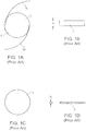
- Figure 1A shows a top view of a cataract surgery lens implant 2.
- a round optic 5 of the implant 2 has haptics 10 which extend from the periphery of the optic.
- the haptics 10 are used to help the optic center and fixate within the capsular bag.
- Figure 1B shows a side view of a cataract surgery lens implant optic 5.
- the thickness t1 of the optic 5 is typically 1 mm or more and is substantially greater than the 0.5 to 0.6 mm thickness of the human cornea.
- the thickness of the optic 5 makes it inappropriate for use as a corneal lens implant.
- Figure 1C shows a top view of a corneal implant 15. Note there are no haptics on the corneal implant.
- Figure 1D shows a side view of corneal implant 15.
- the thickness t2 is substantially less than cataract surgery lens implant 5.
- the thickness t2 of corneal implant 15 would in general be less than the thickness of the human cornea.
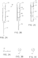
- FIG 2A shows a corneal implant delivery system 18 in partial section.
- Axial pusher 30 has a tip 35 that engages a corneal implant 15 that has been deformed in shape and constrained to fit inside the hollow axial passage 25 of the hollow member 20, as shown in Figure 2B .
- the cross-section of hollow passage 25 may be circular, polygonal, or any other shape that is conducive to constraining the corneal implant 15.
- the hollow axial passage 25 of the hollow member 20 may contain ridges, protrusions, indentations, or recesses (now shown) which help to maintain orientation of the corneal implant as it advances distally of the hollow member (not shown).
- Axial pusher 30 engages one end of the constrained corneal implant 15 to advance the constrained implant through hollow passage 25.
- Figure 2C shows the constrained corneal implant 15 emerging from a distal end of the hollow passage 25 still in its deformed and constrained configuration.
- the corneal implant is able to pass through an entry incision that is less than one-half the width of the corneal implant.
- the hollow member will have an external width from 0.5 mm to 5 mm, preferably from 1 mm to 3 mm and an internal width from 0.3 mm to 4.8 mm, preferably from 0.8 mm to 2.8 mm.
- Figure 3A shows a side view of corneal implant 15 in its non-deformed, non-constrained shape.
- Figure 3B and 3C shows an end on view of the corneal implant 15 as it is moved within the hollow member 20.
- the corneal implant 15 has been deformed and constrained into a rolled configuration.
- the rolled configuration will preferably have a diameter in the range from 0.3 mm to 4.8 mm, more preferably from 0.6 mm to 2.6 mm, to fit into the hollow passage 25 of the hollow member 20.
- Figure 4A-4D shows a corneal implant delivery system with a deformation chamber 27 and a deforming member 28.
- the corneal implant 15 is placed into the chamber 27 in an unconstrained and undeformed configuration and is then deformed into a folded or rolled corneal implant 17 within deformation chamber 27 by deforming member 28.
- Deforming member 28 is moved within deformation chamber 27 to deform and fold corneal implant 15 into a folded or rolled corneal implant 17.
- Figure 4C shows axial pusher 30 engaging deformed corneal implant 17 by implant mover tip 35.
- Figure 4D shows deformed and folded corneal implant 17.
- Axial pusher 30 engages corneal implant 17 to push the deformed constrained implant inside hollow passage 25.
- Figure 4D shows that corneal implant 17 has been advanced by axial pusher 30 out of the hollow passage 25 while retaining a constrained shape.
- the constrained configuration of corneal implant 17 allows passage into the corneal pocket (not shown) through a small incision.
- the presence of the optional deformation chamber 27 and deforming member 28, advantageously allows the corneal implant 15 to be easily deformed into a configuration that will allow it to be placed through a small corneal incision into a corneal pocket.
- Figures 5A-5D show side views of the corneal implant 15 being deformed into an exemplary deformed and folded or pleated corneal implant 17.
- FIGS 6A-6C show a top view of an alternative corneal implant delivery system 100.
- a corneal implant 115 is placed into a deformation area 122.
- a deformation chamber 124 ( Figure 6B ) is formed which deforms the corneal implant 115.
- the corneal implant 115 is folded in half.
- a tip 132 of an axial pusher 130 engages corneal implant 115.
- the hollow member 120 is tapered so that hollow passage 126 is narrower at a distal end 121 that inserts into the corneal pocket. This allows the corneal implant 115 to be deformed into an even smaller cross-section as the implant is advanced distally and through the distal end 121.
- the implant mover tip 132 may also be deformable to fit within the narrowing hollow passage 126.
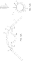
- Figure 7A shows a side cross-sectional view of corneal implant 115 being inserted into corneal pocket 140.
- Figure 7B shows the final shape of corneal implant 115 after it has been inserted into corneal pocket 140 and unfurled or otherwise expanded back to its unconstrained size within cornea 145.
- FIG 8A illustrates a cross-sectional view of a corneal implant prosthesis 50
- Corneal implant 50 is meant to replace a portion of the anterior layers of the cornea.
- the central optic would protrude anteriorly from the rim by 1 to 600 microns. More preferably, the central optic would protrude anteriorly from the rim by 50 to 400 microns.
- the central optic 52 will replace diseased anterior corneal tissue that has been removed.
- the rim 54 is designed to partly or fully surround the center of optic and to fit within the peripheral recesses of a corneal pocket in order to anchor the corneal implant prosthesis to the cornea.
- the rim may be a continuous skirt as illustrated or may be crenellated or otherwise distributed in sections about the periphery of the center optic.
- Figure 8B shows a top view of corneal implant prosthesis 50 which shows the central optic 52 and the rim 54.
- the rim 54 may optionally contain holes or be porous in nature so as to promote growth of corneal tissue into and through the implant, in order to promote retention and biocompatibility.
- FIG. 8C shows a cross-sectional view of corneal implant prosthesis 60 which is meant to replace a full-thickness area of the cornea.
- central optic 62 which protrudes anteriorly from a rim 64.
- the anterior portion of central optic 62 will replace diseased anterior corneal tissue that has been removed.
- the central optic would protrude anteriorly from the rim by 1 to 600 microns. More preferably, the central optic would protrude anteriorly from the rim by 50 to 400 microns.
- corneal implant prosthesis 60 has a posterior portion of central optic 66 which protrudes posteriorly from rim 64. In preferred aspects, the central optic would protrude posteriorly from the rim by 1 to 900 microns.
- the central optic would protrude posteriorly from the rim by 50 to 800 microns.
- the posterior portion of central optic 63 will replace diseased posterior corneal tissue that has been removed.
- the rim 64 will anchor corneal implant prosthesis 60 within the peripheral recesses of the corneal pocket and provide a water-tight seal.
- the rim 64 may optionally contain holes or be porous in nature so as to promote growth of corneal tissue into and through the implant, in order to promote retention and biocompatibility.
- the rim may be formed from any of the lens materials described above.
- Figures 9A-9F show a method of treating an anterior corneal disease process using the methods and apparatus disclosed herein.
- a cross-sectional view of the cornea is seen above and a top view is seen below.
- pocket 40 has been created posterior to anterior diseased cornea 43.
- Figure 9B shows that anterior diseased cornea 43 has been excised with a circular trephine (not shown) to create an open top having a peripheral pocket. The edge of the excision is shown as 45.
- Figure 9B also shows corneal implant 50 resting in the deformation area 122.
- Figure 9C the hollow member 120 has been inserted into pocket 40 through external opening 42 and corneal implant 50 has been folded in half within deformation chamber 124.
- FIG 9D shows that corneal implant 50 has been further deformed into a more compact shape by its movement through narrowing hollow passage 126 and is being extruded into pocket 40.
- Figure 9E shows that corneal implant 50 has been restored to its original shape within corneal pocket 40.
- Central optic 52 fills the space left by excised diseased anterior cornea 43 and restores optical clarity to the cornea.
- Hollow member 120 and implant mover 30 have been withdrawn from corneal pocket 40.
- Figure 9F shows the final appearance of corneal implant 50 fixated within corneal pocket 40.
- FIGs 10A-10F show a method of treating a full-thickness corneal disease (e.g. pseudophakic bullous keratopathy).
- a full-thickness corneal disease e.g. pseudophakic bullous keratopathy
- FIGS. 10A-10F show a method of treating a full-thickness corneal disease (e.g. pseudophakic bullous keratopathy).
- a cross-sectional view of the cornea is seen above and a top view is seen below.
- pocket 40 has been created within the layers of the diseased cornea 41.
- the pocket divides the cornea into diseased anterior cornea 43 and diseased posterior cornea 44.
- Figure 10B shows that anterior diseased cornea 43 has been excised with a circular trephine (not shown). The edge of the excision is shown in dashed lines as 45.
- FIG. 10B also shows corneal implant 60 resting in the deformation charter or area 122.
- the hollow member 120 has been inserted into pocket 40 through external opening 42 and corneal implant 60 has been folded in half within deformation chamber 122.
- Figure 10D shows that corneal implant 60 has been further deformed into a more compact shape by its movement through narrowing hollow passage 126 and is being extruded into pocket 40.
- Figure 10E shows that corneal implant 60 has been restored to its original shape within corneal pocket 40.
- Anterior optic 62 fills the space left by the excised diseased anterior cornea 43.
- the posterior diseased cornea 44 can be excised with low profile curved corneal scissors or some other cutting tool (e.g. plasma blade) inserted through external opening 42.
- Figure 10F shows the final appearance of corneal implant prosthesis 60.
- the rim 64 anchors corneal implant prosthesis 60 within the peripheral recesses of the corneal pocket and provides a water-tight seal.
- posterior optic 63 protrudes through the space left by excised diseased cornea 44.
- posterior optic 63 is optional and is not necessarily required for the corneal implant to properly function. It is to be understood that the relative dimensions, shapes, and angles of the anterior central optic 62, posterior central optic 63, and rim 64, may each be modified to promote improved retention as well as optical qualities all in keeping within the scope of the present disclosure.
- the corneal implant 60 may be introduced into the pocket 40 using the injector system as described previously in Figures 9 and 10 through an opening 46.
- the hollow member 120 may be inserted through the opening 46, and the corneal implant 60 then injected into the pocket 40.
- the corneal implant 60 may be placed into the pocket 40 by constraining the corneal implant 60 into a small diameter configuration (e.g. with forceps) and inserting it through the opening 46 into the pocket 40 without the use of the hollow member 120 (not shown).
- Figure 11A-11F show an embodiment of a corneal implant that can be assembled within the corneal pocket. By assembling individual smaller pieces of the corneal implant within the corneal pocket, a relatively large corneal implant can be constructed while using a relatively small external incision.
- the top portion of Figures 11A and 11B show a cross-sectional view of a cornea with an intra-stromal pocket.
- the bottom portion of Figure 11A shows atop down view of a cornea with an intra-stromal pocket.
- the rim may be made of a relatively rigid material e.g. polymethylmethacrylate (PMMA) and still be inserted through the external opening 42 that is less than half of the diameter of the assembled corneal implant.
- PMMA polymethylmethacrylate
- the vertical dashed lines in the top of the figure and the circular dashed lines in the bottom figure represent an opening 76 left by a circular disk of anterior stromal tissue that has been excised (e.g. with a trephine).
- Figures 11C and 11D show that the optic 72 may fit into opening 76.
- Figures 11E and 11F show that the optic 72 has been attached to the two halves of the rim 70 and 74 to complete assembly of the corneal implant.
- the individual pieces of the corneal implant may be attached to each other by interlocking fittings (not shown), by glue, or any other appropriate mechanical or chemical method of fixation.
- the corneal implant is shown as a three piece prosthesis that replaces part of the cornea.
- a corneal implant can be assembled as two or more pieces within a corneal pocket.
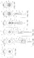
- Figures 12A-12B are end views of the back of a deformation chamber 86 on a hollow member 80 which show how the presence of a protrusion 82 within the deformation chamber can help to maintain the orientation of a corneal implant 90 as it is pushed in an axial direction.
- Deformation chamber 86 includes three hinged sections 80a, 80b, and 80c which make up a hollow member which opens in order to receive corneal implant 90.
- At the lateral aspects of deformation area 80 are two protrusions 82, which help to hold the rim 94 of corneal implant 90 in place.
- Figure 12B shows how sections 80a, 80b, and 80c can be closed by putting together the wings 84 (which together form an axial pusher or implant mover) to create hollow member 80 and deformation chamber 86.
- Corneal implant 90 is now securely fixated within the hollow deformation chamber 86 by the protrusions 82 and can be manipulated.
- the corneal implant 90 can then be moved axially along hollow member 80 by an axial pusher or other implant mover(not shown) without inadvertent rotation of the corneal implant.
- the corneal implant could be colored in any of the embodiments of the disclosure to enhance the aesthetic appearance of the eye or to decrease the amount of light exposure to the eye (e.g. for treatment of aniridia).
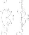
- a corneal implant insertion device 200 includes a deformation chamber 202 defined by two-circular hinged sections 204.
- the hinged sections 204 are attached to wings 206 which permit the hinged sections to be closed in order to capture the corneal implant C, after the implant has been introduced into the deformation chamber, as shown in Figure 13B .
- Protrusions 210 having interior arcuate surfaces 212 are attached to the hinged sections 204 so that the surfaces 212 form radially inwardly directed ramps, as illustrated in Figure 14A .
- closure of the chamber using the wings 206 will curl the corneal implant C into a C-shaped profile, as shown in Figure 14A .
- This can be an advantage over the corneal insertion tool embodiment of Figures 12A and 12B where the edges of the implant are held in a generally open configuration by the outwardly facing surfaces of protrusions 82.
- the corneal implant C comprises a lamellar corneal stromal endothelial transplant graft of approximately 9 mm in diameter and 100 ⁇ m in thickness.
- the deformation chamber 220 has a diameter or width D of approximately 9 mm in order to receive the corneal implant C such that its edges are disposed beneath the arcuate surfaces 212 of the protrusions 210, as illustrated in Figure 13B .
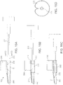
- a pusher shaft 230 having a forward member 232 may be advanced into the deformation chamber 202 of the corneal implant insertion device 200.
- the forward element 232 will have a profile which is similar to the shape of the hollow passage so that it can pass over the protrusions 210 and will typically be compressible so that it can pass into a tapered region 240 of the insertion device, as shown in Figure 1SD.
- the forward member 232 will first be introduced into the constant-diameter portion of the deformation chamber 202, as shown in Figure 15B , and used to advance the corneal implant C forwardly.
- the shaft 30 and forward member 232 will continue to be advanced so that the corneal implant C is pushed from the distal tip of the tapered region 240, as shown in Figure 15C .
- the corneal implant C As the corneal implant C is advanced, its edges will be curved or everted inwardly, as illustrated in Figures 14A through 14C .
- Figure 14A the corneal implant C is shown as it is in Figure 15A .
- Figure 15B the corneal implant C is reduced in diameter with the edges being pushed radially inwardly, as shown in Figure 14B .
- Figure 14C the corneal implant C is released from the proximal tip of the tapered region 240, it has a significantly reduced diameter, as shown in Figure 14C . It is particularly desirable that the corneal implant C be reduced in size to as great an extent as possible but that the leading tips of the implant not touch the interior surface, just as shown in Figure 14C . This reduces the damage or trauma to the delicate corneal endothelial cells during the implantation protocol.
- a graft C such as a DSEK or DMEK graft
- Implant mover 300 has a flexible platform 310 which provides a loading area and which consists of a thin flexible material, such as a plastic.
- Figure 16A shows the DSEK or DMEK graft C on the platform 310 from a top view.
- Figure 16B shows the DSEK or DMEK graft C on the platform 310 in side profile.
- Figure 16E shows the DSEK or DMEK graft on the platform 310 from a front view at the start of the loading process.
- Figure 16E is shown at the same time point of the loading process as Figure 16A and 16B.
- Figure 16C is a top view which shows that when platform 310 is pulled into a hollow member 320 by implant mover member 300 that the flexible platform 310 will become constrained in size and shape. Because the DSEK or DMEK graft C is flexible it will also become constrained in size and shape inside the flexible platform 310.
- Figure 16D shows a side view at the same time point as 16C.
- Figure 16F shows how DSEK or DMEK graft C is restrained inside flexible platform 310 into a small diameter configuration.
- FIGs 16A-D and 16F an internal arcuate protrusion 330 will force the flexible platform 310 and DSEK graft C to curl in a way that engages only the stromal surface, thereby protecting the delicate corneal endothelium located on the inside of the DSEK or DMEK Graft C.
- hollow member 320 is advanced into the corneal or scleral incision.
- Implant mover 300 is then advanced, allowing flexible platform 310 and DSEK Graft C so that DSEK Graft C can unfurl and be released into the anterior chamber.
- Figures 16A-D show an optional bevel to the end of hollow member 320 which advantageously allows for easier insertion into the ocular incision.
- the optional bevel has an angle between 1° and 89°, preferably between 25° and 65°.
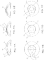
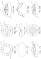
- Figure 17A shows a top view of a corneal scaffold implant 400 which is designed for correcting myopia.
- the scaffold implant 400 is formed from discrete elements 402 which provide a peripheral shape which is a truncate dome. An interior volume of the dome is empty and free from structure.
- Figure 17B is an oblique view which shows the shape of the cornea C prior to insertion of the corneal scaffold implant 400 for myopia into a corneal pocket through incision I.
- Figure 17C shows how the insertion of corneal scaffold implant for myopia 400 flattens the cornea in the direction of the arrow 404 and thereby reduces myopia.
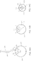
- FIG 18A shows a top view of a corneal scaffold implant 410 which is designed for the purpose of correcting hyperopia.
- the implant 410 comprises elements 412 which form a higher truncated dome than implant 400.
- Figure 18B shows how the insertion of this corneal scaffold implant for hyperopia 410 steepens the cornea in the direction of the arrow and thereby reduces hyperopia.
- FIG 19A shows a top view of a corneal scaffold implant 420 which is designed for the purpose of correcting hyperopic astigmatism.
- the implant 420 comprises two lateral wings 422 joined by a central ring 424.
- Figure 19B shows how the insertion of this corneal scaffold implant for hyperopic astigmatism 420 steepens the central cornea in the direction of the arrow and thereby reduces hyperopia and also flattens the steep axis of the cornea thereby reducing astigmatism.
- Figure 20A shows a top view of a corneal scaffold implant 430 which also contains a lens L shown in hatched lines.
- Figure 20B shows how the insertion of this corneal scaffold implant with a lens 430 corrects refractive error by both changing the shape of the cornea (flattening in this case) and by introducing an additional lens to the optical system.
- the scaffold may be formed from the same polymers as described previously by common techniques, such as molding. Many other shapes and structures for the corneal scaffold implant can be devised for the treatment of myopia, hyperopia, astigmatism, higher order aberrations and ectactic corneal diseases.
- the disclosure includes all of the possible three dimensional shapes and structures where it is not possible for a single plane to pass through all of the elements of the structure.
Description
- 1. Field of the Invention. There are many different types of corneal implants that have been developed for the treatment of refractive error and disease. Because of limitations in the methods of creating corneal pockets, these implants have all been designed for placement in the cornea by creation of a corneal incision which is either similar in size to the smallest dimension of the implant or larger. Recently, two methods of corneal pocket creation have been devised which can create a pocket with an external opening width that is less than the maximum internal width of the pocket. These two methods are pocket creation by the femtosecond laser and, of particular interest, cornea cutting, as described in
US 2004/0243159 and0243160 , invented by the inventor herein. - It is advantageous to have a biocompatible corneal implant that can be placed through an external incision that is less than the width of the implant, especially an external incision that is less than half of the width of the implant. It is particularly advantageous if the corneal implant can be placed through an incision that does not require suturing for closure, typically being 3 mm or less. Such a small external incision also decreases induced surgical astigmatism and speeds up the recovery time for the patient. Moreover, it is useful to have a relatively large implant that can be placed through a relatively small incision. For example a lens implant that is larger is more likely to give good quality vision especially in a patient with large pupils. It is also advantageous to have a simple and reliable delivery system for the corneal implant.
- Intraocular lenses (IOL's) for cataract surgery have been designed to be placed through a small incision. These small incision cataract surgery lenses cannot practically be used within a corneal pocket. Most small incision cataract surgery lens implants are usually too thick to be placed within a corneal pocket. For example the typical thickness of a cataract surgery lens implant is 1 mm or more which is substantially thicker than the human cornea, which is usually between 0.5 to 0.6 mm. Some corneal implants that have been designed only have a thickness of about 0.05 mm. Moreover, the cataract surgery lens implants have haptics, which are extensions from the lens implant designed to keep the lens implant fixated within the capsular bag. Haptics are not present and not necessary for corneal implants. Finally, the cataract surgery lens implants are not designed to be biocompatible with the cornea and would not be tolerated as corneal implants.
- The delivery systems designed for small incision cataract surgery lens implants are not well adapted for use as a delivery system for small incision corneal implants. These delivery systems have been designed for cataract surgery lens implants that are much thicker than the usual corneal implant. The delivery systems for small incision cataract surgery lens implants are designed to accommodate haptics, which would not be present on a corneal lens implant. It has been found that at least some commercially available corneal implants are destroyed when placed through a standard IOL injector. Similarly, biological corneal implants placed through a standard IOL injector will often show severe histological damage, such as endothelial damage.
- Corneal implants can be made of either synthetic materials (e.g. prostheses) or can be biological in origin (e.g. transplant grafts). Recently two new surgical techniques for placement of a lamellar corneal stromal endothelial transplant grafts have been devised. These surgical techniques are useful in the treatment of endothelial diseases of the cornea such as Fuchs' endothelial dystrophy and pseudophakic bullous keratopathy. One of these techniques is referred to as deep lamellar endothelial keratoplasty (DLEK). In this technique a pocket is made within the cornea and diseased corneal endothelium is excised along with a layer of corneal stroma. Healthy lamellar corneal stromal endothelial tissue is then transplanted into the space left by the excised diseased tissue. Another technique is called Descemet's stripping automated endothelial keratoplasty (DSAEK or DSEK). In this technique, a lamellar corneal stromal endothelial transplant graft is automatically created using either a microkeratome or a laser. The diseased corneal endothelium is stripped away with surgical instruments and then the lamellar corneal stromal endothelial transplant graft is inserted into the anterior chamber through a full thickness corneal incision. The graft is then held in place against the stripped posterior corneal stromal surface by an air bubble until the graft is able to heal in position.
- In both DLEK and DSAEK it is advantageous to be able to insert a relatively large transplant atraumatically through a small corneal or scleral incision. A larger transplant has more corneal endothelial cells and should produce better results in the treatment of corneal endothelial diseases. However, a significant problem with prior art methods of inserting corneal transplants into the anterior chamber through a small incision is that they all involve folding of the transplant and grasping of the transplant with forceps. Moreover, the transplant is typically severely compressed as it passes through the corneal incision. Ithas been demonstrated through the use ofvital staining techniques that many of the delicate corneal endothelial cells of a transplant are killed during the prior art insertion process. Like corneal transplant grafts for DSAEK or DLEK, synthetic corneal implants e.g. corneal inlay prostheses are also very delicate. In many cases, these corneal inlays may be as thin as 30 to 40 microns, which make them very easily torn by forceps. Therefore, there is also a need for an improved method to place these corneal inlays atraumatically through a small incision.
- Delivery systems for placement of intraocular lenses (IOLs) into the posterior chamber through a small incision have been described. However, these delivery systems designed for small incision cataract surgery IOLs are not well adapted for use as a delivery system for corneal implants through a small incision. For example, a typical intraocular lens implant may be 1 mm or more in thickness, whereas the typical corneal transplant for DLEK or DSAEK is between 0.1 to 0.15 mm in thickness. Moreover, as has been noted before, the thickness of a corneal inlay prosthesis may be as little as 30 to 40 microns. In addition, the size and shape of an IOL is different from that of a corneal transplant. An IOL is typically 12 to 13 mm in length, 5 to 6 mm wide, and 1 mm or more in thickness, whereas a corneal transplant DSEK graft would typically be circular in shape and would have a diameter of 8 to 9 mm and a thickness from 0.1 mm to 0.2 mm. In the case of a corneal prosthesis implant, the diameter may range from 1 mm to 10 mm and the thickness from 0.01 mm to 0.6 mm. Finally, IOL delivery systems are designed to greatly compress the IOL during the insertion process, whereas this type of compression would be likely to either damage or destroy a living corneal transplant. The amount of compression used for IOL delivery systems could also damage the much thinner corneal implants.
-
US 6,626,941 describes prosthetic implants designed to be implanted in the cornea for modifying the cornea curvature and altering the corneal refractive power for correcting myopia, and myopia with astigmatism, such implants formed of a micro-porous hydrogel material. -
US2006/173539 describes a system comprising a hollow member is used to deliver a constrained corneal implant into a corneal pocket. The hollow member may be tapered and the system may further include an implant deformation chamber and an axial pusher to advance the implant through the hollow member. -
US5,947,975 describes an insertion device for inserting a deformable intraocular lens into the eye. The insertion device has an enclosing member that is attached to the body of the insertion device and that has two hinge portions at a lens receiving section. Further, a retainer member is fitted onto the enclosing member and a holder fitted onto the body. The deformable intraocular lens is placed in the lens receiving section after the enclosing member is opened. When the holder is retracted, the intraocular lens is deformed by a tapered inner wall portion formed at a the tip end of the holder, so that the exterior size of the lens is reduced. Subsequently, a push rod supported by the body is advanced in order to insert the lens into the eye. -
WO 2005082285 describes a lens holder is used to transfer an intraocular lens from a relaxed state into an elastically deformed state so that it can be injected with the aid of a co-operating device into an eye, where it resumes its relaxed state again. The lens holder contains a flexible backing support which can be deformed from an open position, in which it accommodates an intraocular lens in its relaxed state, into a closed position in which it is inserted in said device. The intraocular lens is inserted in the opened lens holder and the latter is then moved into its closed position by bending it. - The present invention is set out by the appended claims. Improved systems and methods for implanting corneal implants are disclosed herein. The phrase "corneal implant" refers to any natural (biological) or synthetic implant or graft that may be implanted into a human cornea. These systems and methods can place a corneal implant through a corneal incision that is substantially less than the width of the implant. The placement of the implant may be within or between any of the layers of the cornea including epithelium, Bowman's membrane, stroma, Descemet's membrane, and endothelium. In preferred aspects, the corneal incision is equal or less than half of the width of the implant. In additional preferred aspects, the system allows the placement of a corneal implant through an incision that is less than or equal to 3 mm, which advantageously avoids the need for suturing of the incision in most cases and also greatly decreases the chance of unwanted induced astigmatism.
- In accordance with a first aspect of the present disclosure, the corneal implant is reversibly deformable in shape to allow its passage through a corneal incision that is equal or less than half of the width of the implant. The corneal implant is bio-compatible with the cornea, the eye, and the body. In certain embodiments, synthetic material which can meet these criteria may potentially be used for the implant. Suitable synthetic materials include one or more compounds selected from the group consisting of collagen, polyurethanes, poly(2-hydroxyethylmethacrylate), polyvinylpyrolidone, polyglycerolmethacrylate, polyvinyl alcohol, polyethylene glycol, polymethacrylic acid, silicones, acrylics, polyfluorocarbons,
and polymers with phosphocholine. In other embodiments, the grafts may comprise human corneas harvested for use in transplants such as grafts or DSEK or a graft which consists only of Descemet's membrane and endothelium. Transplantation of only Descemet's membrane and endothelium is referred to as Descemet's Membrane Endothelial Keratoplasty (DMEK). In the future, biological cornea implants may be obtained from other sources such as animals, genetically modified animals, in vitro cell culture, or the like. - In a preferred embodiment, the material comprises a hydrogel. In additional preferred embodiments, the material comprises polymethacrylic acid-co hydroxyethyl methacrylate (PHEMA/MAA).
- In an alternative preferred embodiment, the corneal implant is formed from a material comprising of a reversibly deformable acrylic copolymer, such as those used for intraocular lenses. These materials have excellent tensile strength and can be elongated as much as 250% before breaking. Such characteristics allow injection to be performed according to the present disclosure without damage to the implant. Examples of suitable materials include copolymers of hydroxyethyl methacrylate and methyl methacrylate (e.g. materials available under the tradenames Contamac Cl26,
Cl 18, Cl21 materials, Benz IOL 25UV and Benzflex 26UV). Inadditional preferred aspects, the deformable polymer is hydrophilic in nature to allow smooth wetting of the optical surface of the implant. Wetability is an important characteristic of corneal implant which allows the tearfilm to act as a good optical interface. In yet other preferred aspects the material contains between 1% and 20% methacrylic acid. More preferably 5 to 10% methacrylic acid, which advantageously allows the linkage of tethering molecules such as polyethylene glycol to the surface of the implant. Tethering molecules will allow reactive moieties to be linked to the surface of the implant to create useful implant characteristics such as promotion of epithelialization or the ability to create chemical bonds with the cornea. Other preferred physical characteristics of the corneal implant material would be a tensile strength in the range of 0.1 to 4 MPa, more preferably a tensile strength in the range of 0.6 to 2.6 MPa. In addition, a modulus of 0.1 to 5 MPa, more preferably a modulus in the range of 0.2 to 3.1 MPa would also be desirable. Although we have described specific types of acrylic copolymers as suitable for corneal implants, other types of materials (e.g. silicone or collagen polymers) which have similar physical and chemical characteristics as those described above could also be used. - In other preferred embodiments, holes or pores may be provided in the implant to increase biocompatibility of the implant by allowing nutritive substances and gasses (e.g., water, glucose, and oxygen) to pass easily through the implant in order to maintain healthy metabolism in the cornea. Instill other preferred embodiments, the polymer material may have thermoplastic properties such that the implant will have one desired shape at one temperature and then deform into another desired shape at a second temperature. In yet other preferred aspects, the corneal implant may comprise one or more separate, smaller components that can be assembled in situ placed inside the corneal pocket. Such in situ assembly advantageously minimizes the incision size needed to insert a corneal implant.
- The corneal implant may be of any shape that allows it to be placed within a corneal pocket. In preferred embodiments, the corneal implant is substantially round. In alternate preferred embodiments, the corneal implant is not round. A corneal implant which is not round has the advantage that it is less likely to rotate within a corneal pocket. This property is useful in the implants which correct for astigmatism.
- In preferred other embodiments, the corneal implant is a lens. The lens can be a monofocal, multifocal, Fresnel, diffractive, prismatic, or other type of lens that can be used to treat refractive error (such as myopia, hyperopia, or astigmatism) presbyopia, or ocular disease e.g. macular degeneration. The lens may also be made of a polymer that can have its refractive properties adjusted permanently or reversibly by electromagnetic energy as described in
U.S. Patent Application 2003/0173691 to Jethmalani . - The corneal implant may comprise a prosthesis that is used to replace or augment a portion of the cornea. Such implants are useful in restoring optical clarity or structural integrity to the cornea in lieu of corneal transplantation. The corneal prosthesis may be used to replace only a partial thickness portion of the cornea or a full thickness portion of the cornea. In preferred aspects, the corneal implant may be coated with extracellular matrix proteins such as collagen, fibronectin, laminin, substance P, insulin-like growth factor-1, or peptide sequences such as fibronectin adhesion-promoting peptide (FAP). In additional preferred aspects, these extracellular matrix proteins and peptides are tethered or otherwise bound to the epithelial side of the corneal implant by the methods described in
U.S. Patent 6,689,165, to Jacob et al. Such surface treatments are intended to promote epithelialization on the surface of a corneal implant. - In alternate preferred embodiments, the surface of the corneal implant may have a texture that promotes epithelialization on the surface of the corneal implant. Textures, such as surface indentations, may be applied to the surface of the corneal implant to promote epithelialization, as described in
U.S. Patent 6,454,800 to Dalton et al. - In yet other alternate preferred embodiments, the corneal implant may be manufactured from a material that promotes epithelialization on the surface of the corneal implant. Examples of such materials include polymers selected from the group consisting of collagen and N-isopropylacrylamide, collagen and 1-ethyl-3.3'(dimethyl-aminopropyl)-carbodiimide as well as collagen and N-hydroxysuccinimide (EDC/NHS). In further preferred aspects, the polymer may additionally contain extracellular matrix proteins such as fibronectin, laminin, substance P, insulin-like growth factor-1, or peptide sequences such as fibronectin adhesion-promoting or peptide (FAP).
- Optionally, at least a portion of the device may contain holes or be porous in nature so as to promote growth of corneal tissue into and through the implant in order to promote retention and biocompatibility. Such porous implants may be fabricated as described in
U.S. Patent 6,976,997 to Noolandi et al . andU.S. Patent 5,300,116 to Chirila et al. - Optionally, at least a portion of the lens or other corneal implant may be colored. Coloration can be useful for cosmetic purposes or for therapeutic purposes e.g. treatment of aniridia. For example, methods of applying biocompatible inks, which are well known in colored contact lens manufacturing, may be used to color the corneal implant. Particular coloring methods are described in
U.S. Patent Applications 2003/0054109 and2003/0025873 , the disclosures of which are incorporated herein by reference. In alternate preferred aspects, the corneal implant may be colored with photosensitive inks that change color with exposure to electromagnetic waves. This allows the color of the corneal implant to be adjusted permanently or reversibly by exposure to electromagnetic waves in vivo. - Optionally, the corneal implant may also contain an ultraviolet filter compound of the benzophenone type such as 3-(2 Benzyotriazolyl)-2-Hydroxy-5-Tert-Octyl-Benzyl Methacryl Amide.
- In alternate preferred embodiments the corneal implant may comprise a scaffold having a three-dimensional structure including discrete elements defining a peripheral shape with a mostly empty interior volume therein. The predetermined shape is selected to provide a vision correction when placed in a corneal pocket. The scaffold can be inserted into a corneal pocket for the purpose of reshaping or supporting the cornea. Reshaping of the cornea is useful for correction of various vision problems including refractive errors as well as for the treatment of ectactic corneal disorders such as keratoconus or pellucid marginal degeneration. In preferred aspects the corneal implant scaffold consists of a three dimensional structure where it is not possible for a single plane to pass through all of the elements of the structure. In other preferred aspects the corneal implant scaffold is reversibly deformable so that it may be introduced to a corneal packet by the devices and methods of the present disclosure. Also preferably, the corneal implant scaffold should have a rigidity that is greater than a mammalian cornea, so that insertion of the scaffold into a corneal pocket will result in either a change in shape of the cornea or be able to provide increased structural strength to the cornea. In preferred aspects the corneal implant scaffold is made of a biocompatible and
reversibly deformable polymer or a biocompatible and reversibly deformable metal or alloy (e.g. gold, titanium, nitinol). In additional preferred aspects the width of the structural elements in the corneal implant scaffold is 0.1 mm to 1 mm, more, preferably 0.3 to 0.6 mm. In preferred aspects the thickness of the structural elements in the scaffold is 0.001 mm to 0.5 mm, more preferably 0.01 mm to 0.06 mm. In alternate preferred aspects the cornea scaffold implant may also include a lens within the structure, which advantageously combines correction of refractive error by both changing of the shape of the cornea and the addition of another lens. - In yet other alternate preferred embodiments, the corneal implant may be a device. Examples of potential implant devices include miniature cameras and aqueous glucose monitors.
- The improved corneal implants of the present disclosure are reversibly deformable into a reduced width shape that allows passage through a corneal incision that is substantially less than the width of the implant when undeformed or unconstrained. In preferred aspects, the implant will be insertable through an incision that is less than or equal to one-half of the width of the implant, preferably being 3 mm or less.
- A system according to the present disclosure comprises a hollow member and implant mover or other axial pusher used to deliver a corneal implant that has been constrained to fit inside an axial hollow passage of the hollow member. The implant may be deformed or constrained in any shape or configuration having a "reduced width" that allows it to be fit inside of the hollow member e.g., rolled or folded. By "reduced width" it is meant that a maximum width of the implant, such as a diameter of a circular lens, is reduced by some threshold amount, typically by at least one-half (50%), often by at least 60%, and sometimes by 65% or more.
- A system according to the present disclosure comprises a hollow member and implant mover used to deliver a corneal implant that has been restrained to fit inside of the hollow member. Once the corneal implant is inside the hollow member, the implant mover is used to move the implant into a corneal pocket or the anterior chamber.
- Optionally, the system may further comprise a deformation chamber where the implant is deformed into a shape and size that will fit inside the hollow member. In preferred aspects, the deformation chamber may contain ridges, protrusions, indentations, or recesses which help to maintain and guide the orientation of the corneal implant within the deformation chamber during the deformation process. In further preferred aspects the deformation chamber will be a size that is appropriate for the type of corneal implant which is being used. For example in the case of a corneal transplant, the minimum internal dimensions of an open deformation chamber should be between 6 and 10 mm, more preferably between 8 and 9 mm. In the case of a corneal implant prosthesis, the minimum internal dimensions of an open deformation chamber dimensions should be between 1 mm and 10mm, more preferably between 2.0 mm and 7 mm. In additional preferred aspects the deformation area may be tapered or funnel shaped, i.e. narrower one end than on the other end. The tapered or funnel shape advantageously facilitates the corneal implant to be restrained to a smaller diameter configuration.
- In other preferred aspects, the interior of the hollow member may contain ridges, protrusions, indentations, or recesses which help to maintain and guide the orientation of the corneal implant as it travels inside of the hollow member. Such surface features will be arranged to prevent rotation of the corneal implant during insertion which might otherwise disorient the implant within the pocket. In additional preferred aspects, the interior of the hollow member may contain ridges, protrusions, indentations, or recesses which guides a lamellar corneal stromal endothelial transplant to deform in a way which allows it to travel through a small incision without the need for folding or being grasped by forceps. The system is designed to allow a corneal transplant to be placed through an incision equal or less than 3 mm. However, the system can also be used to place an implant through an incision that is greater than 3mm.
- Optionally, the system may be designed to be sterile and disposable for single use. This advantageously decreases the chance for contamination and infection. It also obviates the need for the surgeon to autoclave or to provide other methods of sterilization such as ethylene oxide. To insure that the system will be both sterile and single use only we can add one or more of the following features. In preferred aspects one or more components of the system may be made of a polymer which will melt or deform into an unusable shape upon autoclaving.
In additional preferred aspects, the system may have a one way locking mechanism, such that once the tip of the implant mover travels to a certain distance, the implant mover is locked in position inside of the hollow member, thus preventing reloading of another corneal implant. In alternative preferred aspects, the system may be assembled through the use of breakable tabs or snaps, which allows the secure assembly of the disposable component, but which are easily destroyed if there is an attempt to disassemble the system for reuse. - Optionally, the system may be designed so that the corneal implant is pre-loaded inside of the hollow member prior to use by the surgeon. This advantageously minimizes the need for manipulation of the delicate corneal implant by the surgeon, which could result in damage to the corneal implant.
- Once the corneal implant is inside the hollow member, the implant mover or other axial pusher is used to engage and push the implant into the corneal pocket. Optionally, the system may further comprise a deformation chamber where the implant is deformed into a shape and size that will fit inside the hollow member. In other preferred aspects, the deformation chamber may contain ridges, protrusions, indentations, or recesses which help to maintain orientation of the corneal implant within the deformation chamber during the deformation process. Optionally, the hollow member is tapered, i.e., narrower at a distal end than at a proximal end. Such tapering allows additional deformation (size or width reduction) of the implant as it is advanced through the hollow member and passes out through a smaller distal opening. The interior of the hollow member may contain ridges, protrusions, indentations, or recesses which help to maintain orientation of the corneal implant as it travels inside of the hollow member. The system for implant placement is designed to allow an implant to be placed into a corneal pocket with an entry incision that is equal or less than one-half of the width of the implant, however, the system can also be used to place an implant through a corneal incision that is greater than one-half of the width of the implant.
-
- Figures IA, 1B, 1C, and 1D illustrate prior art corneal implants.
-
Figures 2A through 2C illustrates a first embodiment of apparatus. -
Figures 3A through 3C illustrate side views of a corneal implant as it is advanced and constrained by the apparatus ofFigures 2A-2C . -
Figures 4A through 4D illustrate a second embodiment of the apparatus. - Figures SA through SD illustrate side views of a corneal implant as it is advanced and constrained by the apparatus of
Figures 4A-4D . -
Figures 6A through 6C illustrate a third embodiment of the apparatus. -
Figures 7A and 7B illustrate use of the apparatus ofFigures 6A-6C in implanting an implant in a cornea. -
Figures 8A through 8D illustrate preferred corneal implants. -
Figures 9A through 9F illustrate a further implantation protocol. -
Figures 10A through 10F illustrate a further implantation protocol. -
Figures 11A through 11F illustrate a further implantation protocol. -
Figures 12A and 12B illustrate a tool for collapsing and advancing a corneal implant. -
Figures 13A and 13B illustrate an alternative tool for collapsing and advancing a corneal implant. -
Figures 14A and 14C are cross-sectional views of the tool of 13A and 13B showing the implant as it is advanced as shown inFigures 15A through 15D . -
Figures 15A through 15D illustrate use of the tool ofFigures 13A and 13B for advancing and reducing the cross-section of an implant. -
Figures 16A-F illustrate an alternative tool for collapsing and advancing a corneal implant. -
Figures 17A-C illustrate a corneal scaffold embodiment of the corneal implant for the treatment of myopia. -
Figures 18A-B illustrate a corneal scaffold embodiment of the corneal implant for the treatment of hyperopia. -
Figures 19 A-B illustrate a corneal scaffold embodiment of the corneal implant for the treatment of hyperopic astigmatism. -
Figures 20 A-B illustrate a corneal scaffold embodiment of the corneal implant which also includes a lens. -
Figure 1A shows a top view of a cataractsurgery lens implant 2. Around optic 5 of theimplant 2 has haptics 10 which extend from the periphery of the optic. Thehaptics 10 are used to help the optic center and fixate within the capsular bag.Figure 1B shows a side view of a cataract surgerylens implant optic 5. Note that the thickness t1 of theoptic 5 is typically 1 mm or more and is substantially greater than the 0.5 to 0.6 mm thickness of the human cornea. The thickness of theoptic 5 makes it inappropriate for use as a corneal lens implant.
Figure 1C shows a top view of acorneal implant 15. Note there are no haptics on the corneal implant.Figure 1D shows a side view ofcorneal implant 15. Note that the thickness t2 is substantially less than cataractsurgery lens implant 5. The thickness t2 ofcorneal implant 15 would in general be less than the thickness of the human cornea. -
Figure 2A shows a cornealimplant delivery system 18 in partial section. Ahollow member 20 having a distal tip 21 (which is preferably beveled or chamfered) defines hollow axial passage 25 (e.g. an axial lumen).Axial pusher 30 has atip 35 that engages acorneal implant 15 that has been deformed in shape and constrained to fit inside the hollowaxial passage 25 of thehollow member 20, as shown inFigure 2B . The cross-section ofhollow passage 25 may be circular, polygonal, or any other shape that is conducive to constraining thecorneal implant 15. The hollowaxial passage 25 of thehollow member 20 may contain ridges, protrusions, indentations, or recesses (now shown) which help to maintain orientation of the corneal implant as it advances distally of the hollow member (not shown).Axial pusher 30 engages one end of the constrainedcorneal implant 15 to advance the constrained implant throughhollow passage 25.Figure 2C shows the constrainedcorneal implant 15
emerging from a distal end of thehollow passage 25 still in its deformed and constrained configuration. By placing the tip of thehollow member 20 through an incision in the cornea, thecorneal implant 15 may be advanced into the corneal pocket (not shown) through even a very small incision. In preferred aspects, the corneal implant is able to pass through an entry incision that is less than one-half the width of the corneal implant. In those cases, the hollow member will have an external width from 0.5 mm to 5 mm, preferably from 1 mm to 3 mm and an internal width from 0.3 mm to 4.8 mm, preferably from 0.8 mm to 2.8 mm. -
Figure 3A shows a side view ofcorneal implant 15 in its non-deformed, non-constrained shape.Figure 3B and 3C shows an end on view of thecorneal implant 15 as it is moved within thehollow member 20. Note that thecorneal implant 15 has been deformed and constrained into a rolled configuration. The rolled configuration will preferably have a diameter in the range from 0.3 mm to 4.8 mm, more preferably from 0.6 mm to 2.6 mm, to fit into thehollow passage 25 of thehollow member 20. -
Figure 4A-4D shows a corneal implant delivery system with adeformation chamber 27 and a deformingmember 28. In this embodiment, thecorneal implant 15 is placed into thechamber 27 in an unconstrained and undeformed configuration and is then deformed into a folded or rolledcorneal implant 17 withindeformation chamber 27 by
deformingmember 28. Deformingmember 28 is moved withindeformation chamber 27 to deform and foldcorneal implant 15 into a folded or rolledcorneal implant 17.Figure 4C showsaxial pusher 30 engaging deformedcorneal implant 17 byimplant mover tip 35.Figure 4D shows deformed and foldedcorneal implant 17.Axial pusher 30 engagescorneal implant 17 to push the deformed constrained implant insidehollow passage 25.Figure 4D
shows thatcorneal implant 17 has been advanced byaxial pusher 30 out of thehollow passage 25 while retaining a constrained shape. The constrained configuration ofcorneal implant 17 allows passage into the corneal pocket (not shown) through a small incision. The presence of theoptional deformation chamber 27 and deformingmember 28, advantageously allows thecorneal implant 15 to be easily deformed into a configuration that will allow it to be placed through a small corneal incision into a corneal pocket. -
Figures 5A-5D show side views of thecorneal implant 15 being deformed into an exemplary deformed and folded or pleatedcorneal implant 17. -
Figures 6A-6C show a top view of an alternative cornealimplant delivery system 100. Inthis embodiment acorneal implant 115 is placed into adeformation area 122. When the "wings" 123 of the deformation area are closed, a deformation chamber 124 (Figure 6B ) is formed which deforms thecorneal implant 115. In this embodiment, thecorneal implant 115 is folded in half. Atip 132 of anaxial pusher 130 engagescorneal implant 115. Thehollow member 120 is tapered so thathollow passage 126 is narrower at adistal end 121 that inserts into the corneal pocket. This allows thecorneal implant 115 to be deformed into an even smaller cross-section as the implant is advanced distally and through thedistal end 121. Advantageously in this embodiment, theimplant mover tip 132 may also be deformable to fit within the narrowinghollow passage 126. -
Figure 7A shows a side cross-sectional view ofcorneal implant 115 being inserted intocorneal pocket 140.Figure 7B shows the final shape ofcorneal implant 115 after it has been inserted intocorneal pocket 140 and unfurled or otherwise expanded back to its unconstrained size withincornea 145. -
Figure 8A illustrates a cross-sectional view of acorneal implant prosthesis 50Corneal implant 50 is meant to replace a portion of the anterior layers of the cornea. In this embodiment there is acentral optic 52 that protrudes anteriorly from arim 54. In preferred aspects, the central optic would protrude anteriorly from the rim by 1 to 600 microns. More
preferably, the central optic would protrude anteriorly from the rim by 50 to 400 microns. Thecentral optic 52 will replace diseased anterior corneal tissue that has been removed. Therim 54 is designed to partly or fully surround the center of optic and to fit within the peripheral recesses of a corneal pocket in order to anchor the corneal implant prosthesis to the cornea. The rim may be a continuous skirt as illustrated or may be crenellated or otherwise distributed in sections about the periphery of the center optic.Figure 8B shows a top view ofcorneal implant prosthesis 50 which shows thecentral optic 52 and therim 54. Therim 54 may optionally contain holes or be porous in nature so as to promote growth of corneal tissue into and through the implant, in order to promote retention and biocompatibility. -
Figure 8C shows a cross-sectional view ofcorneal implant prosthesis 60 which is meant to replace a full-thickness area of the cornea. In this embodiment there is an anterior portion ofcentral optic 62 which protrudes anteriorly from arim 64. The anterior portion ofcentral optic 62 will replace diseased anterior corneal tissue that has been removed. In preferred aspects, the central optic would protrude anteriorly from the rim by 1 to 600 microns. More preferably, the central optic would protrude anteriorly from the rim by 50 to 400 microns. In additioncorneal implant prosthesis 60 has a posterior portion ofcentral optic 66 which protrudes posteriorly fromrim 64. In preferred aspects, the central optic would protrude posteriorly from the rim by 1 to 900 microns. More preferably, the central optic would protrude posteriorly from the rim by 50 to 800 microns. The posterior portion ofcentral optic 63 will replace diseased posterior corneal tissue that has been removed. Therim 64 will anchorcorneal implant prosthesis 60 within the peripheral recesses of the corneal pocket and provide a water-tight seal. Therim 64 may optionally contain holes or be porous in nature so as to promote growth of corneal tissue into and through the implant, in order to promote retention and biocompatibility. The rim may be formed from any of the lens materials described above. -
Figures 9A-9F show a method of treating an anterior corneal disease process using the methods and apparatus disclosed herein. In eachFigure 9A-F , a cross-sectional view of the cornea is seen above and a top view is seen below. InFigure 9A it is shown thatpocket 40 has been created posterior to anteriordiseased cornea 43.Figure 9B shows that anteriordiseased cornea 43 has been excised with a circular trephine (not shown) to create an open top having a peripheral pocket. The edge of the excision is shown as 45.Figure 9B also showscorneal implant 50 resting in thedeformation area 122. InFigure 9C thehollow member 120 has been inserted intopocket 40 throughexternal opening 42 and corneal
implant 50 has been folded in half withindeformation chamber 124.Figure 9D shows thatcorneal implant 50 has been further deformed into a more compact shape by its movement through narrowinghollow passage 126 and is being extruded intopocket 40.Figure 9E shows thatcorneal implant 50 has been restored to its original shape withincorneal pocket 40. Central optic 52 fills the space left by excised diseasedanterior cornea 43 and restores optical clarity to the cornea.Hollow member 120 andimplant mover 30 have been withdrawn fromcorneal pocket 40.Figure 9F shows the final appearance ofcorneal implant 50 fixated withincorneal pocket 40. -
Figures 10A-10F show a method of treating a full-thickness corneal disease (e.g. pseudophakic bullous keratopathy). In eachfigure 10A-F , a cross-sectional view of the cornea is seen above and a top view is seen below. Infigure 10A it is shown thatpocket 40 has been created within the layers of thediseased cornea 41. The pocket divides the cornea into diseasedanterior cornea 43 anddiseased posterior cornea 44.Figure 10B shows that anteriordiseased cornea 43 has been excised with a circular trephine (not shown). The edge of the excision is shown in dashed lines as 45. - The opening in the anterior cornea within the edge of the
excision 45 is shown atreference number 46.Figure 10B also showscorneal implant 60 resting in the deformation charter orarea 122. InFigure 10C thehollow member 120 has been inserted intopocket 40 throughexternal opening 42 andcorneal implant 60 has been folded in half withindeformation chamber 122.Figure 10D shows thatcorneal implant 60 has been further deformed into a more compact shape by its movement through narrowinghollow passage 126 and is being extruded intopocket 40.Figure 10E shows thatcorneal implant 60 has been restored to its original shape withincorneal pocket 40.Anterior optic 62 fills the space left by the excised diseasedanterior cornea 43. In preferred aspects, aftercorneal implant 60 has been positioned in the pocket, the posteriordiseased cornea 44 can be excised with low profile curved corneal scissors or some other cutting tool (e.g. plasma blade) inserted throughexternal opening 42.Figure 10F shows the final appearance ofcorneal implant prosthesis 60. Note that therim 64 anchorscorneal implant prosthesis 60 within the peripheral recesses of the corneal pocket and provides a water-tight seal. In this embodiment,posterior optic 63 protrudes through the space left by exciseddiseased cornea 44. However,posterior optic 63 is optional and is not necessarily required for the corneal implant to properly function. It is to be understood that the relative dimensions, shapes, and angles of the anteriorcentral optic 62, posteriorcentral optic 63, and rim 64, may each be modified to promote improved retention as well as optical qualities all in keeping within the scope of the present disclosure. - In alternative preferred aspects, the
corneal implant 60 may be introduced into thepocket 40 using the injector system as described previously inFigures 9 and10 through anopening 46. Thehollow member 120 may be inserted through theopening 46, and thecorneal implant 60 then injected into thepocket 40. In yet other alternative preferred aspects,
thecorneal implant 60 may be placed into thepocket 40 by constraining thecorneal implant 60 into a small diameter configuration (e.g. with forceps) and inserting it through theopening 46 into thepocket 40 without the use of the hollow member 120 (not shown). -
Figure 11A-11F show an embodiment of a corneal implant that can be assembled within the corneal pocket. By assembling individual smaller pieces of the corneal implant within the corneal pocket, a relatively large corneal implant can be constructed while using a relatively small external incision. The top portion ofFigures 11A and 11B show a cross-sectional view of a cornea with an intra-stromal pocket. The bottom portion ofFigure 11A shows atop down view of a cornea with an intra-stromal pocket. In bothFigures 11A and 11B , it can be seen that the first half of therim 70 has already been inserted inside the pocket. A second half of therim 74 is being inserted through the small external incision. Note that because the corneal tissue is partially elastic, the rim may be made of a relatively rigid material e.g. polymethylmethacrylate (PMMA) and still be inserted through theexternal opening 42 that is less than half of the diameter of the assembled corneal implant. The vertical dashed lines in the top of the figure and the circular dashed lines in the bottom figure represent anopening 76 left by a circular disk of anterior stromal tissue that has been excised (e.g. with a trephine).Figures 11C and 11D show that the optic 72 may fit intoopening 76.Figures 11E and 11F show that the optic 72 has been attached to the two halves of therim -
Figures 12A-12B are end views of the back of adeformation chamber 86 on ahollow member 80 which show how the presence of aprotrusion 82 within the deformation chamber can help to maintain the orientation of acorneal implant 90 as it is pushed in an axial direction.Deformation chamber 86 includes three hingedsections
which make up a hollow member which opens in order to receivecorneal implant 90. At the lateral aspects ofdeformation area 80 are twoprotrusions 82, which help to hold therim 94 ofcorneal implant 90 in place.Figure 12B shows howsections hollow member 80 anddeformation chamber 86.Corneal implant 90 is now
securely fixated within thehollow deformation chamber 86 by theprotrusions 82 and can be manipulated. Thecorneal implant 90 can then be moved axially alonghollow member 80 by an axial pusher or other implant mover(not shown) without inadvertent rotation of the corneal implant. - Please note at least some portion of the corneal implant could be colored in any of the embodiments of the disclosure to enhance the aesthetic appearance of the eye or to decrease the amount of light exposure to the eye (e.g. for treatment of aniridia).
- Referring now to
Figures 13A and 13B , a cornealimplant insertion device 200 includes adeformation chamber 202 defined by two-circular hingedsections 204. The hingedsections 204 are attached towings 206 which permit the hinged sections to be closed in order to capture the corneal implant C, after the implant has been introduced into the deformation chamber, as shown inFigure 13B . -
Protrusions 210 having interiorarcuate surfaces 212 are attached to the hingedsections 204 so that thesurfaces 212 form radially inwardly directed ramps, as illustrated inFigure 14A . Thus, after the corneal implant C is introduced into thedeformation chamber 202, as illustrated inFigure 13B , closure of the chamber using thewings 206 will curl the corneal implant C into a C-shaped profile, as shown inFigure 14A . This can be an advantage over the corneal insertion tool embodiment ofFigures 12A and 12B where the edges of the implant are held in a generally open configuration by the outwardly facing surfaces ofprotrusions 82. - In a specific embodiment of the corneal implant insertion device of the present disclosure, the corneal implant C comprises a lamellar corneal stromal endothelial transplant graft of approximately 9 mm in diameter and 100 µm in thickness. The deformation chamber 220 has a diameter or width D of approximately 9 mm in order to receive the corneal implant C such that its edges are disposed beneath the
arcuate surfaces 212 of theprotrusions 210, as illustrated inFigure 13B . - Referring now to
Figures 15A through 15D , apusher shaft 230 having aforward member 232 may be advanced into thedeformation chamber 202 of the cornealimplant insertion device 200. Theforward element 232 will have a profile which is similar to the shape of the hollow passage so that it can pass over theprotrusions 210 and will typically be compressible so that it can pass into a taperedregion 240 of the insertion device, as shown in Figure 1SD. Thus, theforward member 232 will first be introduced into the constant-diameter portion of thedeformation chamber 202, as shown inFigure 15B , and used to advance the corneal implant C forwardly. Theshaft 30 andforward member 232 will continue to be advanced so that the corneal implant C is pushed from the distal tip of the taperedregion 240, as shown inFigure 15C . - As the corneal implant C is advanced, its edges will be curved or everted inwardly, as illustrated in
Figures 14A through 14C . InFigure 14A, the corneal implant C is shown as it is inFigure 15A . As it advances forwardly, as shown inFigure 15B , the corneal implant C is reduced in diameter with the edges being pushed radially inwardly, as shown inFigure 14B . Finally, as the corneal implant C is released from the proximal tip of the taperedregion 240, it has a significantly reduced diameter, as shown inFigure 14C . It is particularly desirable that the corneal implant C be reduced in size to as great an extent as possible but that the leading tips of the implant not touch the interior surface, just as shown inFigure 14C . This reduces the damage or trauma to the delicate corneal endothelial cells during the implantation protocol. - In an embodiment illustrated in
Figures 16A-F , a graft C, such as a DSEK or DMEK graft, is placed stromal side down onto the surface ofimplant mover 300.Implant mover 300 has aflexible platform 310 which provides a loading area and which consists of a thin flexible material, such as a plastic.Figure 16A shows the DSEK or DMEK graft C on theplatform 310 from a top view.Figure 16B shows the DSEK or DMEK graft C on theplatform 310 in side profile.Figure 16E shows the DSEK or DMEK graft on theplatform 310 from a front view at the start of the loading process.Figure 16E is shown at the same time point of the loading process asFigure 16A and 16B. Figure 16C is a top view which shows that whenplatform 310 is pulled into ahollow member 320 byimplant mover member 300 that theflexible platform 310 will become constrained in size and shape. Because the DSEK or DMEK graft C is flexible it will also become constrained in size and shape inside theflexible platform 310.Figure 16D shows a side view at the same time point as 16C.Figure 16F shows how DSEK or DMEK graft C is restrained insideflexible platform 310 into a small diameter configuration. InFigures 16A-D and 16F an internalarcuate protrusion 330 will force theflexible platform 310 and DSEK graft C to curl in a way that engages only the stromal surface, thereby protecting the delicate corneal endothelium located on the inside of the DSEK or DMEK Graft C. When DSEK or DMEK graft C is to be inserted into the anterior chamber,hollow member 320 is advanced into the corneal or scleral incision.Implant mover 300 is then advanced, allowingflexible platform 310 and DSEK Graft C so that DSEK Graft C can unfurl and be released into the anterior chamber.Figures 16A-D show an optional bevel to the end ofhollow member 320 which advantageously allows for easier insertion into the ocular incision. The optional bevel has an angle between 1° and 89°, preferably between 25° and 65°. -
Figure 17A shows a top view of acorneal scaffold implant 400 which is designed for correcting myopia. Thescaffold implant 400 is formed fromdiscrete elements 402 which provide a peripheral shape which is a truncate dome. An interior volume of the dome is empty and free from structure.Figure 17B is an oblique view which shows the shape of the cornea C prior to insertion of thecorneal scaffold implant 400 for myopia into a corneal pocket through incision I.Figure 17C shows how the insertion of corneal scaffold implant formyopia 400 flattens the cornea in the direction of thearrow 404 and thereby reduces myopia. -
Figure 18A shows a top view of acorneal scaffold implant 410 which is designed for the purpose of correcting hyperopia. Theimplant 410 compriseselements 412 which form a higher truncated dome thanimplant 400.Figure 18B shows how the insertion of this corneal scaffold implant forhyperopia 410 steepens the cornea in the direction of the arrow and thereby reduces hyperopia. -
Figure 19A shows a top view of acorneal scaffold implant 420 which is designed for the purpose of correcting hyperopic astigmatism. Theimplant 420 comprises twolateral wings 422 joined by acentral ring 424.Figure 19B shows how the insertion of this corneal scaffold implant forhyperopic astigmatism 420 steepens the central cornea in the direction of the arrow and thereby reduces hyperopia and also flattens the steep axis of the cornea thereby reducing astigmatism. -
Figure 20A shows a top view of acorneal scaffold implant 430 which also contains a lens L shown in hatched lines.Figure 20B shows how the insertion of this corneal scaffold implant with alens 430 corrects refractive error by both changing the shape of the cornea (flattening in this case) and by introducing an additional lens to the optical system. - The scaffold may be formed from the same polymers as described previously by common techniques, such as molding. Many other shapes and structures for the corneal scaffold implant can be devised for the treatment of myopia, hyperopia, astigmatism, higher order aberrations and ectactic corneal diseases. The disclosure includes all of the possible three dimensional shapes and structures where it is not possible for a single plane to pass through all of the elements of the structure.
- While the above is a complete description of the preferred embodiments of the invention, various alternatives, modifications, and equivalents may be used. Therefore, the above description should not be taken as limiting the scope of the invention which is defined by the appended claims.
Claims (13)
- A system for delivering corneal implants, said system comprising: a hollow member (120) having a proximal end and a distal end configured for insertion into a pocket within a cornea and having an axial hollow passage(126) which tapers in the distal direction; and an axial pusher (230) disposed in the hollow axial passage of the hollow member and configured to engage and axially advance a constrained corneal implant through the hollow passage, wherein the axial hollow passage includes inwardly oriented arcuate surface (210) configured to evert the edges of the corneal implant radially inwardly as the insert is axially advanced through the passage, wherein the axial pusher (230) includes a flexible carrier for the implant and wherein the carrier has edges which are configured to be everted together with the edges of the corneal implant.
- A system as in claim 1, wherein the axial pusher (230) is tapered in a distal direction.
- A system as in claim 2, wherein the axial pusher (230) is deformable so that it will reduce in diameter as it is distally advanced through the tapered hollow passage.
- A system as in claim 3, wherein the axial pusher (230) has a cross-sectional profile which is similar in shape to the cross-sectional profile of the hollow passage.
- A system as in claim 3 or 4, further comprising an implant deformation chamber (202) coupled to the hollow member (120).
- A system as in any preceding claim, further comprising a corneal implant (C) constrained within the hollow passage on a distal side of the axial pusher.
- A system as in any of claims 1 to 5, further comprising the corneal implant, the corneal implant comprising: a scaffold (400; 410; 420; 430) having a three-dimensional structure including discrete elements defining a peripheral shape with a mostly empty volume therein, wherein the discrete elements define a truncate dome or two lateral wings (422) joined by a central ring (424).
- A system as in any of claims 1 to 5, further comprising the corneal implant, the corneal implant comprising a body defining a peripheral shape selected to provide a vision correction when placed in a corneal pocket, said body composed of a material such that the body has a tensile strength in the range from 0.1 MPa to 4 MPa and a modulus in the range from 0.1 MPa to 5 MPa.
- A system as in claim 8, wherein the material comprises an acrylic copolymer or a silicone or collagen copolymer or a metal, for example wherein the metal is selected from the group consisting of gold, titanium, and nickel titanium alloy.
- A system as in any of claims 7 to 9, wherein the peripheral shape is configured to flatten the cornea when placed in the pocket.
- A system as in any of claims 7 to 9, wherein the peripheral shape is configured to steepen the cornea when placed in the pocket to correct hyperopia.
- A system as in any of claims 7 to 9, wherein the peripheral shape is configured to steepen the central cornea and flatten the steep axis of the cornea when placed in the pocket.
- A system as in any of claims 7 to 12, further comprising a lens (L) configured to change the shape of the cornea when placed in the pocket and to provide additional refractive error correction.
Applications Claiming Priority (3)
| Application Number | Priority Date | Filing Date | Title |
|---|---|---|---|
| US11/741,496 US8029515B2 (en) | 2005-01-31 | 2007-04-27 | Corneal implants and methods and systems for placement |
| EP08780570.1A EP2142150B1 (en) | 2007-04-27 | 2008-04-25 | Systems for placement of corneal implants |
| PCT/US2008/061656 WO2008134573A1 (en) | 2007-04-27 | 2008-04-25 | Corneal implants and methods and systems for placement |
Related Parent Applications (2)
| Application Number | Title | Priority Date | Filing Date |
|---|---|---|---|
| EP08780570.1A Division EP2142150B1 (en) | 2007-04-27 | 2008-04-25 | Systems for placement of corneal implants |
| EP08780570.1A Division-Into EP2142150B1 (en) | 2007-04-27 | 2008-04-25 | Systems for placement of corneal implants |
Publications (2)
| Publication Number | Publication Date |
|---|---|
| EP3434226A1 EP3434226A1 (en) | 2019-01-30 |
| EP3434226B1 true EP3434226B1 (en) | 2020-11-18 |
Family
ID=39929863
Family Applications (4)
| Application Number | Title | Priority Date | Filing Date |
|---|---|---|---|
| EP08780570.1A Active EP2142150B1 (en) | 2007-04-27 | 2008-04-25 | Systems for placement of corneal implants |
| EP20110181836 Active EP2404573B1 (en) | 2007-04-27 | 2008-04-25 | Corneal implants |
| EP15167678.0A Active EP2954873B1 (en) | 2007-04-27 | 2008-04-25 | Corneal implants |
| EP18181352.8A Active EP3434226B1 (en) | 2007-04-27 | 2008-04-25 | Systems for placement of corneal impants |
Family Applications Before (3)
| Application Number | Title | Priority Date | Filing Date |
|---|---|---|---|
| EP08780570.1A Active EP2142150B1 (en) | 2007-04-27 | 2008-04-25 | Systems for placement of corneal implants |
| EP20110181836 Active EP2404573B1 (en) | 2007-04-27 | 2008-04-25 | Corneal implants |
| EP15167678.0A Active EP2954873B1 (en) | 2007-04-27 | 2008-04-25 | Corneal implants |
Country Status (7)
| Country | Link |
|---|---|
| US (1) | US8029515B2 (en) |
| EP (4) | EP2142150B1 (en) |
| JP (4) | JP5323813B2 (en) |
| CN (3) | CN101715334B (en) |
| ES (4) | ES2404174T3 (en) |
| HK (1) | HK1213169A1 (en) |
| WO (1) | WO2008134573A1 (en) |
Families Citing this family (53)
| Publication number | Priority date | Publication date | Assignee | Title |
|---|---|---|---|---|
| US8668735B2 (en) | 2000-09-12 | 2014-03-11 | Revision Optics, Inc. | Corneal implant storage and delivery devices |
| US10835371B2 (en) | 2004-04-30 | 2020-11-17 | Rvo 2.0, Inc. | Small diameter corneal inlay methods |
| US9999497B2 (en) * | 2005-01-31 | 2018-06-19 | Yichieh Shiuey | Corneal implants and methods and systems for placement |
| EP1981437B1 (en) | 2006-01-26 | 2016-05-25 | Wake Forest University Health Sciences | Corneal donor disc medical tool |
| US10555805B2 (en) | 2006-02-24 | 2020-02-11 | Rvo 2.0, Inc. | Anterior corneal shapes and methods of providing the shapes |
| US9271828B2 (en) | 2007-03-28 | 2016-03-01 | Revision Optics, Inc. | Corneal implant retaining devices and methods of use |
| US9549848B2 (en) | 2007-03-28 | 2017-01-24 | Revision Optics, Inc. | Corneal implant inserters and methods of use |
| EP2224881B1 (en) * | 2007-10-16 | 2014-04-23 | Donald Tan | Ophthalmic surgical device for endothelial keratoplasty for descemet's stripping automated endothelial keratoplasty (dsaek) surgery |
| KR101683042B1 (en) | 2008-04-04 | 2016-12-06 | 포사이트 비젼4, 인크. | Therapeutic device for pain management and vision |
| CA2720573C (en) * | 2008-04-04 | 2019-08-13 | Revision Optics, Inc. | Corneal inlay design and methods of correcting vision |
| US9539143B2 (en) | 2008-04-04 | 2017-01-10 | Revision Optics, Inc. | Methods of correcting vision |
| US8636795B2 (en) * | 2008-04-25 | 2014-01-28 | The Regents Of The University Of California | Device to store and inject corneal graft |
| US20120071580A1 (en) * | 2008-07-31 | 2012-03-22 | The Board Of Trustees Of The University Of Illinois | Suturable Hybrid Superporous Hydrogel Keratoprosthesis for Cornea |
| US9168175B2 (en) * | 2008-09-04 | 2015-10-27 | Vladimir Feingold | Method for laser cutting a corneal pocket |
| DE102009007853A1 (en) * | 2009-02-06 | 2010-08-12 | LMU Ludwig-Maximilians-Universität München | Intraocular lenses treated with alkylphosphocholines for pharmacological after-stage prophylaxis |
| US20100241060A1 (en) * | 2009-03-18 | 2010-09-23 | Roizman Keith | Surgical devices and methods |
| US8591025B1 (en) | 2012-09-11 | 2013-11-26 | Nexisvision, Inc. | Eye covering and refractive correction methods for LASIK and other applications |
| ES2649890T3 (en) * | 2009-10-23 | 2018-01-16 | Nexisvision, Inc. | Corneal enervation for the treatment of eye pain |
| US9498385B2 (en) | 2009-10-23 | 2016-11-22 | Nexisvision, Inc. | Conformable therapeutic shield for vision and pain |
| EP2332494A1 (en) * | 2009-12-09 | 2011-06-15 | Neoptics AG | Applicator for inserting lenses |
| PL221349B1 (en) * | 2010-05-04 | 2016-03-31 | Kałużny Bartłomiej Indywidualna Specjalistyczna Praktyka Lekarska | Method and implant for the correction of vision defects |
| GB201011313D0 (en) * | 2010-07-05 | 2010-08-18 | Ucl Business Plc | Implantation devices, methods and implants |
| JP5798304B2 (en) * | 2010-08-19 | 2015-10-21 | 株式会社トップ | Graft insertion device |
| JP2013540521A (en) * | 2010-09-30 | 2013-11-07 | イーチェー シューイー, | Reversibly deformable artificial cornea and method for implantation |
| CA2816031A1 (en) | 2010-10-25 | 2012-05-10 | Nexisvision, Inc. | Methods and apparatus to identify eye coverings for vision |
| KR20140007913A (en) | 2011-02-15 | 2014-01-20 | 웨이브라이트 게엠베하 | Apparatus for assistance in the implantation of a corneal prosthesis in a human eye, and method for executing such an implantation |
| CN102090942B (en) * | 2011-02-17 | 2013-11-06 | 史晓春 | Artificial iris using fastening wires for fixing in eye |
| EP2701644B1 (en) | 2011-04-28 | 2018-05-30 | Nexisvision, Inc. | Eye covering having improved tear flow, comfort, and/or applicability |
| US8678584B2 (en) | 2012-04-20 | 2014-03-25 | Nexisvision, Inc. | Contact lenses for refractive correction |
| US8439833B2 (en) * | 2011-10-18 | 2013-05-14 | Oasis Medical, Inc. | Ophthalmic structure |
| WO2013059813A1 (en) | 2011-10-21 | 2013-04-25 | Revision Optics, Inc. | Corneal implant storage and delivery devices |
| US9465233B2 (en) | 2012-04-20 | 2016-10-11 | Nexisvision, Inc. | Bimodular contact lenses |
| CN104335104B (en) | 2012-04-20 | 2017-06-09 | 内希斯视觉股份有限公司 | For the contact lens of correction of refractive errors |
| EP3014345A2 (en) | 2013-06-26 | 2016-05-04 | Nexisvision, Inc. | Contact lenses for refractive correction |
| US9341864B2 (en) | 2013-11-15 | 2016-05-17 | Nexisvision, Inc. | Contact lenses having a reinforcing scaffold |
| GB2521360B (en) * | 2013-12-17 | 2015-11-18 | Philip Douglas Weston | Surgical device for storage and placement of grafts |
| WO2015116559A1 (en) | 2014-01-29 | 2015-08-06 | Nexisvision, Inc. | Multifocal bimodulus contact lenses |
| AU2015287692A1 (en) | 2014-07-11 | 2017-02-02 | The United States Of America, As Represented By The Secretary, Department Of Health & Human Services | Surgical tool and method for ocular tissue transplantation |
| CA2958213A1 (en) * | 2014-08-26 | 2016-03-03 | Spirox, Inc. | Nasal implants and systems and method of use |
| AU2015385773A1 (en) | 2015-03-12 | 2017-10-05 | Revision Optics, Inc. | Methods of correcting vision |
| CN105520807B (en) * | 2016-02-25 | 2018-05-15 | 王小东 | A kind of anterior chamber eyelid retractor used in penetrating keratoplasty |
| WO2017210316A1 (en) | 2016-05-31 | 2017-12-07 | Qura, Inc. | Implantable intraocular pressure sensors and methods of use |
| JP6752413B2 (en) * | 2016-07-06 | 2020-09-09 | 国立大学法人 岡山大学 | Artificial retina protective equipment |
| USD940865S1 (en) | 2016-08-15 | 2022-01-11 | Board Of Regents, The University Oftexas System | Allograft insertion device |
| CN114404140B (en) * | 2016-09-12 | 2024-04-05 | 雷萨公司 | Laser method and system for aligning a device into an eye structure |
| WO2018066616A1 (en) * | 2016-10-06 | 2018-04-12 | 株式会社北里コーポレーション | Living cell transplanting tool |
| US11324587B2 (en) * | 2017-08-31 | 2022-05-10 | Chandrashekar BALACHANDRAN | Corneal implant |
| CN109481083B (en) | 2017-09-11 | 2021-06-01 | 财团法人工业技术研究院 | Implanting instrument |
| WO2019164940A1 (en) * | 2018-02-20 | 2019-08-29 | Qura, Inc. | Coating for implantable devices |
| IT201800006146A1 (en) | 2018-06-08 | 2019-12-08 | CORNEAL PLANT | |
| US11654048B2 (en) | 2019-04-23 | 2023-05-23 | Miracles In Sight | DSAEK corneal graft assemblies for optimized surgical operations |
| US10806558B1 (en) | 2019-04-23 | 2020-10-20 | The North Carolina Eye Bank, Inc | Corneal graft assemblies for improved surgical operations |
| GB2585888B (en) | 2019-07-19 | 2021-07-21 | Network Medical Products Ltd | Surgical device for storage and placement of grafts |
Family Cites Families (72)
| Publication number | Priority date | Publication date | Assignee | Title |
|---|---|---|---|---|
| US243160A (en) | 1881-06-21 | Teeeitoey | ||
| US4189546A (en) * | 1977-07-25 | 1980-02-19 | Bausch & Lomb Incorporated | Polysiloxane shaped article for use in biomedical applications |
| US5269812A (en) * | 1986-05-16 | 1993-12-14 | White Thomas C | Methods and devices employed in replacement of the corneal endothelium |
| US4708666A (en) * | 1986-09-15 | 1987-11-24 | Amp Incorporated | Triaxial to coaxial connector assembly |
| US4919130A (en) | 1986-11-07 | 1990-04-24 | Nestle S.A. | Tool for inserting compressible intraocular lenses into the eye and method |
| US4706666A (en) | 1987-03-03 | 1987-11-17 | Sheets John H | Positioning implement for intraocular lens |
| KR940011206B1 (en) * | 1987-06-15 | 1994-11-29 | 커러비젼 인코오퍼레이티드 | Holder for inserting corneal curvature adjustment ring |
| US5108428A (en) * | 1988-03-02 | 1992-04-28 | Minnesota Mining And Manufacturing Company | Corneal implants and manufacture and use thereof |
| US5211660A (en) | 1988-05-02 | 1993-05-18 | University Of South Florida | Method for performing epikeratophakia by electrofusion |
| CA2026028A1 (en) * | 1989-09-25 | 1991-03-26 | George P. Stoy | Corneal lens implant |
| US5344449A (en) | 1990-07-03 | 1994-09-06 | Allergan, Inc. | Intraocular lenses, fixation member assemblies and methods for making same |
| US5653725A (en) * | 1990-07-12 | 1997-08-05 | University Of Miami | Instrument for initiating an intralamellar channel |
| JP2981920B2 (en) * | 1990-11-30 | 1999-11-22 | 京セラ株式会社 | Artificial cornea |
| AU650156B2 (en) | 1992-08-05 | 1994-06-09 | Lions Eye Institute Limited | Keratoprosthesis and method of producing the same |
| US5300118A (en) * | 1992-09-21 | 1994-04-05 | Keravision | Adjustable devices for corneal curvature adjustment |
| US6712848B1 (en) | 1992-09-30 | 2004-03-30 | Staar Surgical Company, Inc. | Deformable intraocular lens injecting apparatus with transverse hinged lens cartridge |
| US5772666A (en) | 1992-09-30 | 1998-06-30 | Staar Surgical Company, Inc. | Deformable intraocular lens injecting apparatus with deformable tip plunger |
| ES2143501T3 (en) * | 1992-10-02 | 2000-05-16 | Bausch & Lomb Surgical Inc | ANNULAR IMPLANT FOR CORNEA. |
| US5653715A (en) * | 1993-03-09 | 1997-08-05 | Chiron Vision Corporation | Apparatus for preparing an intraocular lens for insertion |
| EP0712297B1 (en) * | 1993-08-02 | 2004-03-17 | Addition Technology, Inc | Segmented pliable intrastromal corneal insert |
| WO1995003755A1 (en) * | 1993-08-02 | 1995-02-09 | Keravision, Inc. | Segmented preformed intrastromal corneal insert |
| US5489301A (en) * | 1993-09-03 | 1996-02-06 | Barber; John C. | Corneal prosthesis |
| AU1915595A (en) | 1994-02-09 | 1995-08-29 | Kabi Pharmacia Ophthalmics, Inc. | Rapid implantation of shape transformable optical lenses |
| ES2316664T3 (en) | 1994-08-05 | 2009-04-16 | BAUSCH & LOMB INCORPORATED | A METHOD FOR CONTAINING AN INTRAOCULAR LENS. |
| US20040073303A1 (en) * | 1995-06-07 | 2004-04-15 | Harry J. Macey | Radial intrastromal corneal insert and a method of insertion |
| US5919228A (en) * | 1995-06-27 | 1999-07-06 | Hennig; Juergen | Corneal insert |
| US6280470B1 (en) * | 1995-10-20 | 2001-08-28 | Gholam A. Peyman | Intrastromal corneal modification |
| US5735858A (en) | 1996-01-26 | 1998-04-07 | Allergan | IOL insertion apparatus and method for using same |
| FR2744013B1 (en) * | 1996-01-30 | 1998-04-24 | Corneal Ind | KERATOPROTHESIS DEVICE |
| JP2001509692A (en) * | 1996-06-27 | 2001-07-24 | ヘニング,ジューゲン | Corneal insert, corneal insert insertion device, and method for correcting refractive power of the eye |
| US5947975A (en) * | 1997-03-07 | 1999-09-07 | Canon Staar Co., Inc. | Inserting device for deformable intraocular lens |
| US5919197A (en) | 1997-05-05 | 1999-07-06 | Surgical Concepts, Inc. | Insertion of multiple folded lens into the eye |
| US20020055753A1 (en) | 1997-12-18 | 2002-05-09 | Thomas A. Silvestrini | Corneal implant methods and pliable implant therefor |
| US6050999A (en) | 1997-12-18 | 2000-04-18 | Keravision, Inc. | Corneal implant introducer and method of use |
| US6217171B1 (en) | 1998-05-26 | 2001-04-17 | Novartis Ag | Composite ophthamic lens |
| ES2220111T3 (en) | 1998-08-12 | 2004-12-01 | Commonwealth Scientific And Industrial Research Organisation | CORNEAL COATING. |
| US6102946A (en) * | 1998-12-23 | 2000-08-15 | Anamed, Inc. | Corneal implant and method of manufacture |
| US6626941B2 (en) | 1998-12-23 | 2003-09-30 | Anamed, Inc. | Corneal implant and method of manufacture |
| US6450642B1 (en) | 1999-01-12 | 2002-09-17 | California Institute Of Technology | Lenses capable of post-fabrication power modification |
| JP4003332B2 (en) * | 1999-01-26 | 2007-11-07 | 東レ株式会社 | Monomers for ophthalmic lenses, polymers using the same, ophthalmic lenses and contact lenses |
| JP2000325369A (en) * | 1999-05-17 | 2000-11-28 | Menicon Co Ltd | Artificial cornea |
| AUPQ197799A0 (en) * | 1999-08-02 | 1999-08-26 | Commonwealth Scientific And Industrial Research Organisation | Hydrophilic biomedical compositions |
| US6271281B1 (en) * | 1999-08-26 | 2001-08-07 | Medennium, Inc. | Homopolymers containing stable elasticity inducing crosslinkers and ocular implants made therefrom |
| US6827440B2 (en) | 2000-01-03 | 2004-12-07 | Wesley Jessen Company | Colored contact lens with a more natural appearance |
| US6436092B1 (en) * | 2000-03-21 | 2002-08-20 | Gholam A. Peyman | Adjustable universal implant blank for modifying corneal curvature and methods of modifying corneal curvature therewith |
| US6689165B2 (en) | 2000-03-31 | 2004-02-10 | Board Of Supervisors Of Louisana State University And Agricultural And Mechanical College | Surface modifications for enhanced epithelialization |
| US20020116056A1 (en) * | 2000-12-21 | 2002-08-22 | Kirk James F. | Device for controllably altering the curvature of the cornea |
| DE60231485D1 (en) | 2001-03-16 | 2009-04-23 | Novartis Ag | PROCESS FOR PRODUCING A DYED CONTACT LENS |
| JP2004535251A (en) * | 2001-07-17 | 2004-11-25 | シノプトクス, インコーポレーテッド | Small incision lens and method of using the same |
| US7037312B2 (en) * | 2001-09-07 | 2006-05-02 | Canon-Staar Co., Inc. | Insertion device for deformable intraocular lens |
| WO2003044946A2 (en) * | 2001-10-12 | 2003-05-30 | Humanoptics Ag | Device for folding an intraocular lens and system for storing an intraocular lens |
| US6786926B2 (en) | 2001-11-09 | 2004-09-07 | Minu, L.L.C. | Method and apparatus for alignment of intracorneal inlay |
| US20070100445A1 (en) * | 2003-02-03 | 2007-05-03 | Shadduck John H | Intraocular lenses and business methods |
| CN2545994Y (en) * | 2002-04-28 | 2003-04-23 | 马伟建 | Polyvinyl alcohol copolymer aquagel soft artificial cornea |
| JP2003325572A (en) | 2002-05-08 | 2003-11-18 | Canon Star Kk | System for inserting intraocular insertion lens |
| US20030232287A1 (en) * | 2002-06-14 | 2003-12-18 | Bango Joseph J. | Method for stromal corneal repair and refractive alteration using photolithography |
| JP2005532094A (en) | 2002-06-18 | 2005-10-27 | ザ・ボード・オブ・トラスティーズ・オブ・ザ・レランド・スタンフォード・ジュニア・ユニバーシティ | Artificial cornea |
| US6855163B2 (en) | 2002-07-19 | 2005-02-15 | Minu, Llc | Gradual correction of corneal refractive error using multiple inlays |
| US20060252981A1 (en) | 2002-12-05 | 2006-11-09 | Hikaru Matsuda | Biocompatible implant and use of the same |
| US7223275B2 (en) | 2003-05-27 | 2007-05-29 | Yichieh Shiuey | System for cutting the cornea of an eye |
| US7276071B2 (en) * | 2004-01-05 | 2007-10-02 | Board Of Supervisors Of Louisiana State University And Agricultural And Mechanical College | Intraocular lens injector |
| US20080119864A1 (en) * | 2004-02-27 | 2008-05-22 | Klaus Deinzer | Lens Holder for an Insertion Device for Deformable Intra-Ocular Lenses |
| CN100500115C (en) * | 2004-05-03 | 2009-06-17 | 姚晓明 | Artificial cornea made of multiporous nanometer carbon-polyvinyl alcohol hydrogel |
| CN1282449C (en) * | 2004-06-21 | 2006-11-01 | 于洪泉 | Dilating ring special for curing glaucoma |
| WO2006015490A1 (en) * | 2004-08-13 | 2006-02-16 | Ottawa Health Research Institute | Ophthalmic devices and related methods and compositions |
| US20060173539A1 (en) * | 2005-01-31 | 2006-08-03 | Yichieh Shiuey | Corneal implants and methods and systems for placement |
| US20060235428A1 (en) * | 2005-04-14 | 2006-10-19 | Silvestrini Thomas A | Ocular inlay with locator |
| US20060235430A1 (en) | 2005-04-15 | 2006-10-19 | Intralens Vision, Inc. | Corneal implant injector assembly and methods of use |
| US20060235513A1 (en) * | 2005-04-18 | 2006-10-19 | Price Francis W Jr | Corneal implants and methods of use |
| CA2609866C (en) * | 2005-06-13 | 2013-07-16 | Alcon, Inc. | Ophthalmic and otorhinolaryngological device materials |
| US8088161B2 (en) * | 2005-07-28 | 2012-01-03 | Visioncare Ophthalmic Technologies Inc. | Compressed haptics |
| KR101375841B1 (en) * | 2006-07-11 | 2014-03-17 | 리포쿠스 그룹 인코포레이티드 | Screral prosthesis for treating presbyopia and other eye disorders and related devices and methods |
-
2007
- 2007-04-27 US US11/741,496 patent/US8029515B2/en active Active
-
2008
- 2008-04-25 ES ES11181836T patent/ES2404174T3/en active Active
- 2008-04-25 JP JP2010506542A patent/JP5323813B2/en active Active
- 2008-04-25 WO PCT/US2008/061656 patent/WO2008134573A1/en active Application Filing
- 2008-04-25 EP EP08780570.1A patent/EP2142150B1/en active Active
- 2008-04-25 EP EP20110181836 patent/EP2404573B1/en active Active
- 2008-04-25 ES ES08780570.1T patent/ES2690320T3/en active Active
- 2008-04-25 EP EP15167678.0A patent/EP2954873B1/en active Active
- 2008-04-25 CN CN200880013866.9A patent/CN101715334B/en active Active
- 2008-04-25 EP EP18181352.8A patent/EP3434226B1/en active Active
- 2008-04-25 CN CN201510184890.0A patent/CN104814809A/en active Pending
- 2008-04-25 ES ES18181352T patent/ES2854999T3/en active Active
- 2008-04-25 CN CN201110317621.9A patent/CN102397116B/en active Active
- 2008-04-25 ES ES15167678T patent/ES2768577T3/en active Active
-
2013
- 2013-03-25 JP JP2013062381A patent/JP5944339B2/en active Active
-
2014
- 2014-04-08 JP JP2014079488A patent/JP5806361B2/en active Active
-
2015
- 2015-03-17 JP JP2015053763A patent/JP2015110089A/en active Pending
-
2016
- 2016-02-04 HK HK16101354.0A patent/HK1213169A1/en unknown
Non-Patent Citations (1)
| Title |
|---|
| None * |
Also Published As
| Publication number | Publication date |
|---|---|
| HK1213169A1 (en) | 2016-06-30 |
| EP2954873A1 (en) | 2015-12-16 |
| EP3434226A1 (en) | 2019-01-30 |
| JP2014128739A (en) | 2014-07-10 |
| WO2008134573A1 (en) | 2008-11-06 |
| ES2854999T3 (en) | 2021-09-23 |
| JP5323813B2 (en) | 2013-10-23 |
| CN101715334B (en) | 2015-04-22 |
| CN101715334A (en) | 2010-05-26 |
| EP2404573B1 (en) | 2013-03-27 |
| JP2015110089A (en) | 2015-06-18 |
| JP2010524654A (en) | 2010-07-22 |
| ES2404174T3 (en) | 2013-05-24 |
| CN104814809A (en) | 2015-08-05 |
| ES2690320T3 (en) | 2018-11-20 |
| EP2954873B1 (en) | 2019-11-06 |
| EP2404573A1 (en) | 2012-01-11 |
| JP2013126583A (en) | 2013-06-27 |
| EP2142150B1 (en) | 2018-08-15 |
| CN102397116A (en) | 2012-04-04 |
| EP2142150A1 (en) | 2010-01-13 |
| ES2768577T3 (en) | 2020-06-23 |
| JP5806361B2 (en) | 2015-11-10 |
| JP5944339B2 (en) | 2016-07-05 |
| US20070244559A1 (en) | 2007-10-18 |
| CN102397116B (en) | 2016-06-22 |
| US8029515B2 (en) | 2011-10-04 |
| EP2142150A4 (en) | 2012-01-04 |
Similar Documents
| Publication | Publication Date | Title |
|---|---|---|
| EP3434226B1 (en) | Systems for placement of corneal impants | |
| US20190374332A1 (en) | Corneal implants and methods and systems for placement | |
| EP1845897B1 (en) | Corneal implants and systems for placement | |
| US8636795B2 (en) | Device to store and inject corneal graft | |
| CA2623906C (en) | Intraocular lens | |
| US8556967B2 (en) | Interior bag for a capsular bag and injector | |
| JP2003519531A (en) | Iris fixed intraocular lens and transplantation method | |
| CZ2005565A3 (en) | Cartridge for storing and/or introduction of eye implant |
Legal Events
| Date | Code | Title | Description |
|---|---|---|---|
| PUAI | Public reference made under article 153(3) epc to a published international application that has entered the european phase |
Free format text: ORIGINAL CODE: 0009012 |
|
| STAA | Information on the status of an ep patent application or granted ep patent |
Free format text: STATUS: THE APPLICATION HAS BEEN PUBLISHED |
|
| AC | Divisional application: reference to earlier application |
Ref document number: 2142150 Country of ref document: EP Kind code of ref document: P |
|
| AK | Designated contracting states |
Kind code of ref document: A1 Designated state(s): AT BE BG CH CY CZ DE DK EE ES FI FR GB GR HR HU IE IS IT LI LT LU LV MC MT NL NO PL PT RO SE SI SK TR |
|
| STAA | Information on the status of an ep patent application or granted ep patent |
Free format text: STATUS: REQUEST FOR EXAMINATION WAS MADE |
|
| 17P | Request for examination filed |
Effective date: 20190730 |
|
| RBV | Designated contracting states (corrected) |
Designated state(s): AT BE BG CH CY CZ DE DK EE ES FI FR GB GR HR HU IE IS IT LI LT LU LV MC MT NL NO PL PT RO SE SI SK TR |
|
| STAA | Information on the status of an ep patent application or granted ep patent |
Free format text: STATUS: EXAMINATION IS IN PROGRESS |
|
| 17Q | First examination report despatched |
Effective date: 20191023 |
|
| GRAP | Despatch of communication of intention to grant a patent |
Free format text: ORIGINAL CODE: EPIDOSNIGR1 |
|
| STAA | Information on the status of an ep patent application or granted ep patent |
Free format text: STATUS: GRANT OF PATENT IS INTENDED |
|
| INTG | Intention to grant announced |
Effective date: 20200602 |
|
| GRAS | Grant fee paid |
Free format text: ORIGINAL CODE: EPIDOSNIGR3 |
|
| GRAA | (expected) grant |
Free format text: ORIGINAL CODE: 0009210 |
|
| STAA | Information on the status of an ep patent application or granted ep patent |
Free format text: STATUS: THE PATENT HAS BEEN GRANTED |
|
| AC | Divisional application: reference to earlier application |
Ref document number: 2142150 Country of ref document: EP Kind code of ref document: P |
|
| AK | Designated contracting states |
Kind code of ref document: B1 Designated state(s): AT BE BG CH CY CZ DE DK EE ES FI FR GB GR HR HU IE IS IT LI LT LU LV MC MT NL NO PL PT RO SE SI SK TR |
|
| REG | Reference to a national code |
Ref country code: GB Ref legal event code: FG4D |
|
| REG | Reference to a national code |
Ref country code: CH Ref legal event code: NV Representative=s name: SERVOPATENT GMBH, CH Ref country code: CH Ref legal event code: EP |
|
| REG | Reference to a national code |
Ref country code: IE Ref legal event code: FG4D |
|
| REG | Reference to a national code |
Ref country code: DE Ref legal event code: R096 Ref document number: 602008063489 Country of ref document: DE |
|
| REG | Reference to a national code |
Ref country code: AT Ref legal event code: REF Ref document number: 1334908 Country of ref document: AT Kind code of ref document: T Effective date: 20201215 |
|
| REG | Reference to a national code |
Ref country code: NL Ref legal event code: FP |
|
| REG | Reference to a national code |
Ref country code: AT Ref legal event code: MK05 Ref document number: 1334908 Country of ref document: AT Kind code of ref document: T Effective date: 20201118 |
|
| PG25 | Lapsed in a contracting state [announced via postgrant information from national office to epo] |
Ref country code: PT Free format text: LAPSE BECAUSE OF FAILURE TO SUBMIT A TRANSLATION OF THE DESCRIPTION OR TO PAY THE FEE WITHIN THE PRESCRIBED TIME-LIMIT Effective date: 20210318 Ref country code: FI Free format text: LAPSE BECAUSE OF FAILURE TO SUBMIT A TRANSLATION OF THE DESCRIPTION OR TO PAY THE FEE WITHIN THE PRESCRIBED TIME-LIMIT Effective date: 20201118 Ref country code: NO Free format text: LAPSE BECAUSE OF FAILURE TO SUBMIT A TRANSLATION OF THE DESCRIPTION OR TO PAY THE FEE WITHIN THE PRESCRIBED TIME-LIMIT Effective date: 20210218 Ref country code: GR Free format text: LAPSE BECAUSE OF FAILURE TO SUBMIT A TRANSLATION OF THE DESCRIPTION OR TO PAY THE FEE WITHIN THE PRESCRIBED TIME-LIMIT Effective date: 20210219 |
|
| PG25 | Lapsed in a contracting state [announced via postgrant information from national office to epo] |
Ref country code: BG Free format text: LAPSE BECAUSE OF FAILURE TO SUBMIT A TRANSLATION OF THE DESCRIPTION OR TO PAY THE FEE WITHIN THE PRESCRIBED TIME-LIMIT Effective date: 20210218 Ref country code: SE Free format text: LAPSE BECAUSE OF FAILURE TO SUBMIT A TRANSLATION OF THE DESCRIPTION OR TO PAY THE FEE WITHIN THE PRESCRIBED TIME-LIMIT Effective date: 20201118 Ref country code: IS Free format text: LAPSE BECAUSE OF FAILURE TO SUBMIT A TRANSLATION OF THE DESCRIPTION OR TO PAY THE FEE WITHIN THE PRESCRIBED TIME-LIMIT Effective date: 20210318 Ref country code: LV Free format text: LAPSE BECAUSE OF FAILURE TO SUBMIT A TRANSLATION OF THE DESCRIPTION OR TO PAY THE FEE WITHIN THE PRESCRIBED TIME-LIMIT Effective date: 20201118 Ref country code: PL Free format text: LAPSE BECAUSE OF FAILURE TO SUBMIT A TRANSLATION OF THE DESCRIPTION OR TO PAY THE FEE WITHIN THE PRESCRIBED TIME-LIMIT Effective date: 20201118 Ref country code: AT Free format text: LAPSE BECAUSE OF FAILURE TO SUBMIT A TRANSLATION OF THE DESCRIPTION OR TO PAY THE FEE WITHIN THE PRESCRIBED TIME-LIMIT Effective date: 20201118 |
|
| REG | Reference to a national code |
Ref country code: LT Ref legal event code: MG9D |
|
| PG25 | Lapsed in a contracting state [announced via postgrant information from national office to epo] |
Ref country code: HR Free format text: LAPSE BECAUSE OF FAILURE TO SUBMIT A TRANSLATION OF THE DESCRIPTION OR TO PAY THE FEE WITHIN THE PRESCRIBED TIME-LIMIT Effective date: 20201118 |
|
| PG25 | Lapsed in a contracting state [announced via postgrant information from national office to epo] |
Ref country code: EE Free format text: LAPSE BECAUSE OF FAILURE TO SUBMIT A TRANSLATION OF THE DESCRIPTION OR TO PAY THE FEE WITHIN THE PRESCRIBED TIME-LIMIT Effective date: 20201118 Ref country code: CZ Free format text: LAPSE BECAUSE OF FAILURE TO SUBMIT A TRANSLATION OF THE DESCRIPTION OR TO PAY THE FEE WITHIN THE PRESCRIBED TIME-LIMIT Effective date: 20201118 Ref country code: SK Free format text: LAPSE BECAUSE OF FAILURE TO SUBMIT A TRANSLATION OF THE DESCRIPTION OR TO PAY THE FEE WITHIN THE PRESCRIBED TIME-LIMIT Effective date: 20201118 Ref country code: RO Free format text: LAPSE BECAUSE OF FAILURE TO SUBMIT A TRANSLATION OF THE DESCRIPTION OR TO PAY THE FEE WITHIN THE PRESCRIBED TIME-LIMIT Effective date: 20201118 Ref country code: LT Free format text: LAPSE BECAUSE OF FAILURE TO SUBMIT A TRANSLATION OF THE DESCRIPTION OR TO PAY THE FEE WITHIN THE PRESCRIBED TIME-LIMIT Effective date: 20201118 |
|
| REG | Reference to a national code |
Ref country code: DE Ref legal event code: R097 Ref document number: 602008063489 Country of ref document: DE |
|
| PG25 | Lapsed in a contracting state [announced via postgrant information from national office to epo] |
Ref country code: DK Free format text: LAPSE BECAUSE OF FAILURE TO SUBMIT A TRANSLATION OF THE DESCRIPTION OR TO PAY THE FEE WITHIN THE PRESCRIBED TIME-LIMIT Effective date: 20201118 |
|
| REG | Reference to a national code |
Ref country code: ES Ref legal event code: FG2A Ref document number: 2854999 Country of ref document: ES Kind code of ref document: T3 Effective date: 20210923 |
|
| PLBE | No opposition filed within time limit |
Free format text: ORIGINAL CODE: 0009261 |
|
| STAA | Information on the status of an ep patent application or granted ep patent |
Free format text: STATUS: NO OPPOSITION FILED WITHIN TIME LIMIT |
|
| 26N | No opposition filed |
Effective date: 20210819 |
|
| PG25 | Lapsed in a contracting state [announced via postgrant information from national office to epo] |
Ref country code: MC Free format text: LAPSE BECAUSE OF FAILURE TO SUBMIT A TRANSLATION OF THE DESCRIPTION OR TO PAY THE FEE WITHIN THE PRESCRIBED TIME-LIMIT Effective date: 20201118 Ref country code: SI Free format text: LAPSE BECAUSE OF FAILURE TO SUBMIT A TRANSLATION OF THE DESCRIPTION OR TO PAY THE FEE WITHIN THE PRESCRIBED TIME-LIMIT Effective date: 20201118 |
|
| PG25 | Lapsed in a contracting state [announced via postgrant information from national office to epo] |
Ref country code: LU Free format text: LAPSE BECAUSE OF NON-PAYMENT OF DUE FEES Effective date: 20210425 |
|
| REG | Reference to a national code |
Ref country code: BE Ref legal event code: MM Effective date: 20210430 |
|
| PG25 | Lapsed in a contracting state [announced via postgrant information from national office to epo] |
Ref country code: IE Free format text: LAPSE BECAUSE OF NON-PAYMENT OF DUE FEES Effective date: 20210425 |
|
| PG25 | Lapsed in a contracting state [announced via postgrant information from national office to epo] |
Ref country code: IS Free format text: LAPSE BECAUSE OF FAILURE TO SUBMIT A TRANSLATION OF THE DESCRIPTION OR TO PAY THE FEE WITHIN THE PRESCRIBED TIME-LIMIT Effective date: 20210318 |
|
| PG25 | Lapsed in a contracting state [announced via postgrant information from national office to epo] |
Ref country code: BE Free format text: LAPSE BECAUSE OF NON-PAYMENT OF DUE FEES Effective date: 20210430 |
|
| PG25 | Lapsed in a contracting state [announced via postgrant information from national office to epo] |
Ref country code: CY Free format text: LAPSE BECAUSE OF FAILURE TO SUBMIT A TRANSLATION OF THE DESCRIPTION OR TO PAY THE FEE WITHIN THE PRESCRIBED TIME-LIMIT Effective date: 20201118 |
|
| PGFP | Annual fee paid to national office [announced via postgrant information from national office to epo] |
Ref country code: NL Payment date: 20230426 Year of fee payment: 16 |
|
| PG25 | Lapsed in a contracting state [announced via postgrant information from national office to epo] |
Ref country code: HU Free format text: LAPSE BECAUSE OF FAILURE TO SUBMIT A TRANSLATION OF THE DESCRIPTION OR TO PAY THE FEE WITHIN THE PRESCRIBED TIME-LIMIT; INVALID AB INITIO Effective date: 20080425 |
|
| PGFP | Annual fee paid to national office [announced via postgrant information from national office to epo] |
Ref country code: IT Payment date: 20230419 Year of fee payment: 16 Ref country code: FR Payment date: 20230425 Year of fee payment: 16 Ref country code: ES Payment date: 20230503 Year of fee payment: 16 Ref country code: DE Payment date: 20230427 Year of fee payment: 16 Ref country code: CH Payment date: 20230502 Year of fee payment: 16 |
|
| PGFP | Annual fee paid to national office [announced via postgrant information from national office to epo] |
Ref country code: GB Payment date: 20230427 Year of fee payment: 16 |