EP3434118B1 - Ultrasonic atomizing sheet, and electronic cigarette atomizing core and atomizer - Google Patents
Ultrasonic atomizing sheet, and electronic cigarette atomizing core and atomizer Download PDFInfo
- Publication number
- EP3434118B1 EP3434118B1 EP16902998.0A EP16902998A EP3434118B1 EP 3434118 B1 EP3434118 B1 EP 3434118B1 EP 16902998 A EP16902998 A EP 16902998A EP 3434118 B1 EP3434118 B1 EP 3434118B1
- Authority
- EP
- European Patent Office
- Prior art keywords
- guide body
- liquid guide
- electronic cigarette
- sleeve
- ring
- Prior art date
- Legal status (The legal status is an assumption and is not a legal conclusion. Google has not performed a legal analysis and makes no representation as to the accuracy of the status listed.)
- Active
Links
Images




Classifications
-
- A—HUMAN NECESSITIES
- A24—TOBACCO; CIGARS; CIGARETTES; SIMULATED SMOKING DEVICES; SMOKERS' REQUISITES
- A24F—SMOKERS' REQUISITES; MATCH BOXES; SIMULATED SMOKING DEVICES
- A24F40/00—Electrically operated smoking devices; Component parts thereof; Manufacture thereof; Maintenance or testing thereof; Charging means specially adapted therefor
- A24F40/40—Constructional details, e.g. connection of cartridges and battery parts
- A24F40/46—Shape or structure of electric heating means
-
- A—HUMAN NECESSITIES
- A24—TOBACCO; CIGARS; CIGARETTES; SIMULATED SMOKING DEVICES; SMOKERS' REQUISITES
- A24F—SMOKERS' REQUISITES; MATCH BOXES; SIMULATED SMOKING DEVICES
- A24F40/00—Electrically operated smoking devices; Component parts thereof; Manufacture thereof; Maintenance or testing thereof; Charging means specially adapted therefor
- A24F40/05—Devices without heating means
-
- A—HUMAN NECESSITIES
- A24—TOBACCO; CIGARS; CIGARETTES; SIMULATED SMOKING DEVICES; SMOKERS' REQUISITES
- A24F—SMOKERS' REQUISITES; MATCH BOXES; SIMULATED SMOKING DEVICES
- A24F40/00—Electrically operated smoking devices; Component parts thereof; Manufacture thereof; Maintenance or testing thereof; Charging means specially adapted therefor
- A24F40/40—Constructional details, e.g. connection of cartridges and battery parts
- A24F40/44—Wicks
-
- A—HUMAN NECESSITIES
- A24—TOBACCO; CIGARS; CIGARETTES; SIMULATED SMOKING DEVICES; SMOKERS' REQUISITES
- A24F—SMOKERS' REQUISITES; MATCH BOXES; SIMULATED SMOKING DEVICES
- A24F40/00—Electrically operated smoking devices; Component parts thereof; Manufacture thereof; Maintenance or testing thereof; Charging means specially adapted therefor
- A24F40/40—Constructional details, e.g. connection of cartridges and battery parts
- A24F40/48—Fluid transfer means, e.g. pumps
- A24F40/485—Valves; Apertures
-
- A—HUMAN NECESSITIES
- A24—TOBACCO; CIGARS; CIGARETTES; SIMULATED SMOKING DEVICES; SMOKERS' REQUISITES
- A24F—SMOKERS' REQUISITES; MATCH BOXES; SIMULATED SMOKING DEVICES
- A24F47/00—Smokers' requisites not otherwise provided for
-
- A—HUMAN NECESSITIES
- A61—MEDICAL OR VETERINARY SCIENCE; HYGIENE
- A61M—DEVICES FOR INTRODUCING MEDIA INTO, OR ONTO, THE BODY; DEVICES FOR TRANSDUCING BODY MEDIA OR FOR TAKING MEDIA FROM THE BODY; DEVICES FOR PRODUCING OR ENDING SLEEP OR STUPOR
- A61M11/00—Sprayers or atomisers specially adapted for therapeutic purposes
- A61M11/005—Sprayers or atomisers specially adapted for therapeutic purposes using ultrasonics
-
- A—HUMAN NECESSITIES
- A61—MEDICAL OR VETERINARY SCIENCE; HYGIENE
- A61M—DEVICES FOR INTRODUCING MEDIA INTO, OR ONTO, THE BODY; DEVICES FOR TRANSDUCING BODY MEDIA OR FOR TAKING MEDIA FROM THE BODY; DEVICES FOR PRODUCING OR ENDING SLEEP OR STUPOR
- A61M15/00—Inhalators
- A61M15/0085—Inhalators using ultrasonics
-
- A—HUMAN NECESSITIES
- A61—MEDICAL OR VETERINARY SCIENCE; HYGIENE
- A61M—DEVICES FOR INTRODUCING MEDIA INTO, OR ONTO, THE BODY; DEVICES FOR TRANSDUCING BODY MEDIA OR FOR TAKING MEDIA FROM THE BODY; DEVICES FOR PRODUCING OR ENDING SLEEP OR STUPOR
- A61M15/00—Inhalators
- A61M15/06—Inhaling appliances shaped like cigars, cigarettes or pipes
-
- B—PERFORMING OPERATIONS; TRANSPORTING
- B05—SPRAYING OR ATOMISING IN GENERAL; APPLYING FLUENT MATERIALS TO SURFACES, IN GENERAL
- B05B—SPRAYING APPARATUS; ATOMISING APPARATUS; NOZZLES
- B05B17/00—Apparatus for spraying or atomising liquids or other fluent materials, not covered by the preceding groups
- B05B17/04—Apparatus for spraying or atomising liquids or other fluent materials, not covered by the preceding groups operating with special methods
- B05B17/06—Apparatus for spraying or atomising liquids or other fluent materials, not covered by the preceding groups operating with special methods using ultrasonic or other kinds of vibrations
-
- B—PERFORMING OPERATIONS; TRANSPORTING
- B05—SPRAYING OR ATOMISING IN GENERAL; APPLYING FLUENT MATERIALS TO SURFACES, IN GENERAL
- B05B—SPRAYING APPARATUS; ATOMISING APPARATUS; NOZZLES
- B05B17/00—Apparatus for spraying or atomising liquids or other fluent materials, not covered by the preceding groups
- B05B17/04—Apparatus for spraying or atomising liquids or other fluent materials, not covered by the preceding groups operating with special methods
- B05B17/06—Apparatus for spraying or atomising liquids or other fluent materials, not covered by the preceding groups operating with special methods using ultrasonic or other kinds of vibrations
- B05B17/0607—Apparatus for spraying or atomising liquids or other fluent materials, not covered by the preceding groups operating with special methods using ultrasonic or other kinds of vibrations generated by electrical means, e.g. piezoelectric transducers
-
- A—HUMAN NECESSITIES
- A24—TOBACCO; CIGARS; CIGARETTES; SIMULATED SMOKING DEVICES; SMOKERS' REQUISITES
- A24F—SMOKERS' REQUISITES; MATCH BOXES; SIMULATED SMOKING DEVICES
- A24F40/00—Electrically operated smoking devices; Component parts thereof; Manufacture thereof; Maintenance or testing thereof; Charging means specially adapted therefor
- A24F40/10—Devices using liquid inhalable precursors
-
- A—HUMAN NECESSITIES
- A61—MEDICAL OR VETERINARY SCIENCE; HYGIENE
- A61M—DEVICES FOR INTRODUCING MEDIA INTO, OR ONTO, THE BODY; DEVICES FOR TRANSDUCING BODY MEDIA OR FOR TAKING MEDIA FROM THE BODY; DEVICES FOR PRODUCING OR ENDING SLEEP OR STUPOR
- A61M2205/00—General characteristics of the apparatus
- A61M2205/82—Internal energy supply devices
- A61M2205/8206—Internal energy supply devices battery-operated
Definitions
- the present invention belongs to the technical field of electronic cigarette, and particularly relates to an electronic cigarette atomization core and an electronic cigarette atomizer.
- CN 203 448 228 U discloses an ultrasonic atomizing sheet.
- CN 105 559 151 A discloses an ultrasonic atomizer and electronic cigarette.
- an ultrasonic atomization piece includes a piezoelectric ceramic main body, one surface of the piezoelectric ceramic main body is in contact with a positive electrode conducting layer, the other surface of the piezoelectric ceramic main body is in contact with a negative electrode conducting layer, and the positive electrode conducting layer and the negative electrode conducting layer are electrically connected by a welded conducting wire. Since the ultrasonic atomization piece will produce oscillation at work, the positive electrode conducting layer and the negative electrode conducting layer will be continuously impacted, such that the conducting wire is disconnected at the welding place and is damaged easily, which affects the reliability of circuit connection, and leads to unreliable work and a short service life.
- the existing ultrasonic atomization piece has the shortcomings of unreliable circuit connection, unreliable work, poor atomization effect and short service life.
- the objective of the present invention is to provide an improved electronic cigarette atomization core and an improved electronic cigarette atomizer in view of the shortcomings of the above prior art.
- the present invention has the beneficial effects that the circuit connection is reliable, the work is reliable, the atomization effect is good, and the service life is long.
- An electronic cigarette atomization core comprising an ultrasonic atomization piece that includes a piezoelectric ceramic main body; one surface of the piezoelectric ceramic main body is in contact with a positive electrode conducting layer; and the other surface of the piezoelectric ceramic main body is in contact with a negative electrode conducting layer
- the ultrasonic atomization piece is structurally characterized in that the negative electrode conducting layer extends to the surface of the piezoelectric ceramic main body on which the positive electrode conducting layer is located along a side edge of the piezoelectric ceramic main body, and a plurality of convex point areas are provided on the edge of the negative electrode conducting layer.
- the negative electrode conducting layer, the piezoelectric ceramic main body and the positive electrode conducting layer form an entirety, thereby simplifying the conducting structure, meanwhile, the negative electrode conducting layer is unlikely to be broken off by the oscillation of the piezoelectric ceramic main body, therefore the electrical connection is reliable, the working reliability is high, and the service life is long.
- the electronic cigarette atomization core includes a first sleeve, a second sleeve, a first liquid guide body and a second liquid guide body; one end of the first sleeve is provided in the second sleeve; the first liquid guide body is fixed between the first sleeve and the second sleeve, and one end of the first liquid guide body is in contact with the second liquid guide body; a liquid inlet hole is provided in the second sleeve, and the first liquid guide body is communicated with the liquid inlet hole; and the second liquid guide body is in contact with the ultrasonic atomization piece.
- the second sleeve is provided in a liquid control ring; and an adjusting hole is provided in the liquid control ring.
- the size of the liquid inlet hole can be adjusted by rotating the liquid control ring so as to control the liquid amount.
- the ultrasonic atomization piece is provided in a mounting base.
- the mounting base is provided in a bottom part of the second sleeve
- the first liquid guide body is fixed in the mounting base
- the second liquid guide body and the first liquid guide body are sequentially arranged along an outflow direction of the atomizing gas.
- the mounting base is provided in a top part of the first sleeve
- the second liquid guide body is provided on the mounting base, and the side edge of the second liquid guide body stretches out from the mounting base and is in contact with the first liquid guide body; the top end of the second sleeve is detachably connected with a top cover; and the first liquid guide body and the second liquid guide body are sequentially arranged along the outflow direction of the atomizing gas.
- At least one through hole is provided in the second liquid guide body.
- At least one minipore which penetrates through the ultrasonic atomization piece is provided in the ultrasonic atomization piece.
- a vent groove is provided in the surface in which the ultrasonic atomization piece is in contact with the second liquid guide body.
- a depression part is provided at the middle of the second liquid guide body, and the through hole is provided in the depression part.
- the minipore can enable the gas to pass by, but the liquid cannot pass by, therefore it is convenient to take away the smoke on the surface of the second liquid guide body, and the atomization efficiency is improved. Due to the vent groove, the airflow passes between the ultrasonic atomization piece and the second liquid guide body and is mixed with the atomized smoke, so that the smoke is finer and smoother, and the particle sizes of granules are more uniform.
- the contact area between the ultrasonic atomization piece and the second liquid guide body can be reduced, therefore, the consumption energy absorbed by the second liquid guide body is reduced, the start up speed of the ultrasonic atomization piece is high, and the user experience is improved; and moreover, it can also be avoided that the air pressure produced by the work of the ultrasonic atomization piece flushes the second liquid guide body away from the ultrasonic atomization piece, therefore, the lamination between the second liquid guide body and the ultrasonic atomization piece is better, and the normal supply of tobacco tar is not affected.
- the present invention further includes an electronic cigarette atomizer, including the electronic cigarette atomization core in any one of the above solutions, a liquid storage cavity and an airflow passage; wherein the liquid storage cavity is communicated with the liquid inlet hole; and one surface, away from the ultrasonic atomization piece, of the second liquid guide body is communicated with the airflow passage.
- the airflow passage includes an air outlet pipe provided in the first sleeve; an air inlet passage is provided between an inner wall of the first sleeve and an outer wall of the air outlet pipe; the bottom end of the air outlet pipe is communicated with an upper surface of the second liquid guide body; the top end of the air outlet pipe is in fixed connection with a suction nozzle base, and the air outlet pipe is communicated with the inner cavity of a suction nozzle on the suction nozzle base; an air inlet is provided in the suction nozzle base; and the air inlet passage is communicated with the air inlet and the surface, away from the ultrasonic atomization piece, of the second liquid guide body.
- the bottom end of the second sleeve is provided in the top part of an outer ring; a second fixing ring is provided in the outer ring; an insulating ring is provided in the second fixing ring; a negative electrode spring is provided at the outside of the insulating ring; a positive electrode spring is provided in the insulating ring; and the negative electrode spring is in contact with the negative electrode conducting layer of the ultrasonic atomization piece through a negative electrode ring, and the positive electrode spring is in contact with the positive electrode conducting layer of the ultrasonic atomization piece through a positive electrode ring.
- the structure is compact.
- the airflow passage includes an air outlet pipe whose bottom end is provided in the top cover; an air inlet passage is provided between the air outlet pipe and the top cover; the bottom end of the air outlet pipe is communicated with the upper surface of the second liquid guide body; the top end of the air outlet pipe is in fixed connection with a suction nozzle base, and the air outlet pipe is communicated with the inner cavity of a suction nozzle on the suction nozzle base; an air inlet is provided in the suction nozzle base; and the air inlet passage is communicated with the air inlet and the second liquid guide body.
- a base is provided in the first sleeve; a bottom plug is provided on the base, and the top end of the bottom plug stretches into the insulating ring; a negative electrode spring is provided at the outside of the insulating ring; a positive electrode spring is provided in the insulating ring; and the negative electrode spring is in contact with the negative electrode conducting layer of the ultrasonic atomization piece through a negative electrode ring, and the positive electrode spring is in contact with the positive electrode conducting layer of the ultrasonic atomization piece through a positive electrode ring.
- the structure is compact.
- the present invention has the advantages of simple structure, reliable electrical connection, reliable work, high atomization speed, good smoke taste and long service life.
- top end refers to the end close to a suction nozzle of an atomizer, namely the end on an outflow direction of the atomizing gas; and so-called bottom end refers to the end opposite to the position of the top end.
- atomization core in embodiment 1 of the present invention includes a first sleeve 54 and a second sleeve 55; an ultrasonic atomization piece 1 is provided on one end of the second sleeve 55, the other end of the second sleeve 55 is in fixed connection with the first sleeve 54, a connecting end of the first sleeve 54 extends to the surface of the ultrasonic atomization piece 1 and is not in contact with the ultrasonic atomization piece 1; the part below a top end of the first sleeve 54 is provided in the second sleeve 55; a first liquid guide body 3 is fixed between the first sleeve 54 and the second sleeve 55, one end of the first liquid guide body 3 extends along the axial direction of the first sleeve 54 to contact with the surface of a second liquid guide body 4; a liquid inlet hole 56 is provided in the second sleeve 55; and the second liquid guide body
- the second sleeve 55 is provided in a liquid control ring 57; and an adjusting hole 58 is provided in the liquid control ring 57.
- the first liquid guide body 3 is cylindrical tobacco tar guide cotton with two open ends and is sheathed on the first sleeve.
- the thickness of the side wall of a top end of the first sleeve is larger than the thickness of the side wall of the rest part (actually, a boss 51 is formed on an outer wall of the top end of the first sleeve), after thread below the boss at the top end of the second sleeve is in screw joint with the first sleeve, a liquid control ring (being a cylinder with two open ends actually) is sheathed at the outside of the second sleeve, the liquid control ring can be rotated, when the adjusting hole is overlapped with the liquid inlet hole, the liquid inlet volume is the largest, when the adjusting hole is stagger to the liquid inlet hole, the liquid inlet volume is reduced, and the liquid inlet hole is even closed.
- a silica gel piece 59 is provided on the first sleeve on one end, away from the liquid control ring, of the boss 51.
- the liquid control ring is hermetically connected with the second sleeve through a sealing ring 60.
- the ultrasonic atomization piece 1 is provided in a mounting base 14, the mounting base 14 is provided in a bottom part of the second sleeve 55, the first liquid guide body 3 is fixed in the mounting base 14, and the second liquid guide body 4 and the first liquid guide body 3 are sequentially arranged along an outflow direction of the atomizing gas.
- the mounting base can be a silica gel base to buffer the oscillating force of the ultrasonic atomization piece, so as to prevent the damage of the ultrasonic atomization piece and prolong the service life of the ultrasonic atomization piece.
- the ultrasonic atomization piece 1 of the present invention includes a piezoelectric ceramic main body 10; one surface of the piezoelectric ceramic main body 10 is in contact with a positive electrode conducting layer 11; and the other surface of the piezoelectric ceramic main body 10 is in contact with a negative electrode conducting layer 12, the negative electrode conducting layer 12 extends to the surface of the piezoelectric ceramic main body 10 on which the positive electrode conducting layer 11 is located along a side edge of the piezoelectric ceramic main body 10, and a plurality of convex point areas 13 (the edges of the convex points are circular arc-shaped) are provided on the edge of the negative electrode conducting layer 12.
- the conducting layer can be set as a silver layer.
- the structure of the atomization core of embodiment 2 of the present invention is as shown in Fig. 4 , in the embodiment, the part above the bottom end of the first sleeve 54 is provided in the second sleeve 55, the mounting base 14 is provided in the bottom part of the second sleeve 55, the first liquid guide body 3 is fixed in the mounting base 14, and the second liquid guide body 4 and the first liquid guide body 3 are sequentially arranged along the outflow direction of the atomizing gas (i.e., the liquid is transferred reverse to the gravity direction).
- the mounting base 14 is provided in the top part of the first sleeve 54; the second liquid guide body 4 is provided on the mounting base 14, and the side edge of the second liquid guide body 4 stretches out from the mounting base 14 and is in contact with the first liquid guide body 3; the top end of the second sleeve 55 is connected with a top cover 9; and the first liquid guide body 3 and the second liquid guide body 4 are sequentially arranged along the outflow direction of the atomizing gas.
- the boss 51 is provided at the top end of the first sleeve, threads are provided on the first sleeves on both sides of the boss, the second sleeve is in screw joint with the first sleeve; and the top cover 9 is in screw joint with the top end (i.e., the upper side of the boss) of the first sleeve.
- the interior of the top cover 9 is of a hollow structure.
- the silica gel piece 59 is provided at the top end of the top cover 9.
- a liquid storage cavity 2 is provided above the ultrasonic atomization piece 1, and the upper part of the atomization core is provided in the liquid storage cavity 1;
- an airflow passage 5 of the atomizer includes an air outlet pipe 52 provided in the first sleeve 54; an air inlet passage 53 is provided between the inner wall of the first sleeve 54 and the outer wall of the air outlet pipe 52; the bottom end of the air outlet pipe 52 is communicated with an upper surface of the second liquid guide body 4; the top end of the air outlet pipe 52 is in fixed connection with a suction nozzle base 6, and the air outlet pipe 52 is communicated with the inner cavity of a suction nozzle 7 on the suction nozzle base 6; an air inlet 8 is provided in the suction nozzle base 6; and the air inlet passage 53 is communicated with the air inlet 8 and the second liquid guide body 4.
- the silica gel piece 59 at the top end of the first sleeve is in contact with an air inlet ring 22; the outer wall of the air inlet ring 22 is in screw joint with the inner wall of an end cover 23; the end cover 23 is provided in an outer pipe 24; and the top end of the outer pipe 24 is connected with the bottom end of the suction nozzle base. Sealing rings are provided between the air inlet ring 22 and the end cover 23 and between the suction nozzle base and the outer pipe for sealing.
- An air adjusting ring 25 for adjusting the air flow amount on the air inlet 8 is further provided on the suction nozzle base, an air adjusting hole 26 is provided in the air adjusting ring 25, the air adjusting ring can be rotated, and when the position of the air adjusting hole is overlapped with the position of the air inlet, the air inflow amount is the largest.
- the bottom end of the second sleeve 55 is provided in the top part of the outer ring 15; a fixing ring 16 is provided in the outer ring 15; an insulating ring 17 is provided in the fixing ring 16; a negative electrode spring 18 is provided at the outside of the insulating ring 17; a positive electrode spring 19 is provided in the insulating ring 17; and the negative electrode spring 18 is in contact with the negative electrode of the ultrasonic atomization piece 1 through a negative electrode ring 20, and the positive electrode spring 19 is in contact with the positive electrode of the ultrasonic atomization piece 1 through a positive electrode ring 21.
- the outer ring 15 is provided in a base 57, and the top end of the base is in screw joint with the bottom end of the outer pipe 24 and seals the liquid storage cavity.
- a bottom plug 58 is provided on the base 57, and the top end of the bottom plug 58 stretches into the insulating ring 17; a negative electrode spring 18 is provided at the outside of the insulating ring 17; a positive electrode spring 19 is provided in the insulating ring 17; the positive electrode spring 19 is in contact with the top end of the bottom plug; and the negative electrode spring 18 is in contact with the negative electrode of the ultrasonic atomization piece 1 through a negative electrode ring 20, and the positive electrode spring 19 is in contact with the positive electrode of the ultrasonic atomization piece 1 through a positive electrode ring 21.
- the bottom end of the bottom plug 58 is in contact with an electrode ring 27, and the electrode ring 27 is provided in the inner part of the lower end of the base and is insulated from the base by an insulating part 28.
- the airflow passage 5 includes the air outlet pipe 52 whose bottom end is provided in the top cover 9; the air inlet passage 53 is provided between the air outlet pipe 52 and the top cover 9; the bottom end of the air outlet pipe 52 is communicated with the upper surface of the second liquid guide body 4; the top end of the air outlet pipe 52 is in fixed connection with the suction nozzle base 6, and the air outlet pipe 52 is communicated with the inner cavity of the suction nozzle 7 on the suction nozzle base 6; the air inlet 8 is provided in the suction nozzle base 6; and the air inlet passage 53 is communicated with the air inlet 8 and the second liquid guide body 4.
- the top cover 9 is in contact with the air inlet ring 22; the outer wall of the air inlet ring 22 is in screw joint with the inner wall of the end cover 23; the end cover 23 is provided in the outer pipe 24; and the top end of the outer pipe 24 is connected with the bottom end of the suction nozzle base 6. Sealing rings are provided between the air inlet ring 22 and the end cover 23 and between the suction nozzle base 6 and the outer pipe for sealing.
- a bottom ring 29 is provided in the first sleeve 54; the bottom plug 58 is provided on the bottom ring 29, and the top end of the bottom plug 58 stretches into the insulating ring 17; the negative electrode spring 18 is provided at the outside of the insulating ring 17; the positive electrode spring 19 is provided in the insulating ring 17; and the negative electrode spring 18 is in contact with the negative electrode of the ultrasonic atomization piece 1 through a negative electrode ring 20, and the positive electrode spring 19 is in contact with the positive electrode of the ultrasonic atomization piece 1 through a positive electrode ring 21.
- the bottom end of the bottom plug 58 is in contact with the electrode ring 27, the electrode ring 27 is provided in the inner part of the lower end of the base and is insulated from the base by the insulating part 28, the top end of the base 57 is in fixed connection with a lower end cover 32, and the lower end cover 32 is connected with the bottom end of the outer pipe through a first fixing ring 30 and seals the liquid storage cavity.
- One end of the negative electrode spring 18 is in contact with the negative electrode ring 20, and the other end of the negative electrode spring is in contact with a second fixing ring 31 provided between the insulating ring 17 and the first sleeve 54.
- At least one through hole 401 is provided in the second liquid guide body 4.
- a depression part 402 is provided at the middle of the second liquid guide body 4, and the through hole 401 is provided in the depression part 402.
- the liquid guide cotton at the depression part 402 at the middle is thinner, the amount of the liquid absorbed by the depression part 402 is smaller, and thus the problems that the atomization is overdue caused by excessive accumulated liquid, and that the start of the ultrasonic atomization piece 1 is slow resulting from the fact that the second liquid guide body 4 absorbs the heat on the ultrasonic atomization piece 1 are solved.
- At least one minipore 101 (the minipore 101 penetrates through the ultrasonic atomization piece 1) which is communicated with the through hole 401 is provided in the ultrasonic atomization piece 1, the aperture of the minipore 101 is about 0.1-200 microns, thereby guaranteeing that the liquid cannot pass by the minipore 101 and only the gas can pass by.
- a vent groove 102 (the surface provided with the vent groove 102 of the ultrasonic atomization piece 1 is in contact with the second liquid guide body 4) is provided in the surface, opposite to the positive electrode conducting layer 11, of the ultrasonic atomization piece 1, and the vent groove 102 is communicated with the through hole 401.
- the airflow enters from the vent groove 102 and quickly takes away the atomizing gas on the surface of the second liquid guide body 4, so that the ultrasonic atomization piece 1 is started quickly, the atomizing gas is finer and smoother, and the particle sizes of the granules are more uniform.
Landscapes
- Health & Medical Sciences (AREA)
- Engineering & Computer Science (AREA)
- Animal Behavior & Ethology (AREA)
- Anesthesiology (AREA)
- Biomedical Technology (AREA)
- Heart & Thoracic Surgery (AREA)
- Hematology (AREA)
- Life Sciences & Earth Sciences (AREA)
- General Health & Medical Sciences (AREA)
- Public Health (AREA)
- Veterinary Medicine (AREA)
- Pulmonology (AREA)
- Bioinformatics & Cheminformatics (AREA)
- Special Spraying Apparatus (AREA)
- Apparatuses For Generation Of Mechanical Vibrations (AREA)
Description
- The present invention belongs to the technical field of electronic cigarette, and particularly relates to an electronic cigarette atomization core and an electronic cigarette atomizer.
-
CN 203 448 228 U discloses an ultrasonic atomizing sheet.CN 105 559 151 A discloses an ultrasonic atomizer and electronic cigarette. - The existing ultrasonic electronic cigarette has the following shortcomings at work:
Firstly, an ultrasonic atomization piece includes a piezoelectric ceramic main body, one surface of the piezoelectric ceramic main body is in contact with a positive electrode conducting layer, the other surface of the piezoelectric ceramic main body is in contact with a negative electrode conducting layer, and the positive electrode conducting layer and the negative electrode conducting layer are electrically connected by a welded conducting wire. Since the ultrasonic atomization piece will produce oscillation at work, the positive electrode conducting layer and the negative electrode conducting layer will be continuously impacted, such that the conducting wire is disconnected at the welding place and is damaged easily, which affects the reliability of circuit connection, and leads to unreliable work and a short service life. - Secondly, as the ultrasonic atomization piece will produce air pressure at work, a liquid guide body covered on the surface of the ultrasonic atomization piece will be impacted, resulting in the fact that the ultrasonic atomization piece is not laminated with the liquid guide body, which leads to idle vibration of the ultrasonic atomization piece, affects the atomization effect and causes a shortened service life of the ultrasonic atomization piece easily.
- The existing ultrasonic atomization piece has the shortcomings of unreliable circuit connection, unreliable work, poor atomization effect and short service life. The objective of the present invention is to provide an improved electronic cigarette atomization core and an improved electronic cigarette atomizer in view of the shortcomings of the above prior art. The present invention has the beneficial effects that the circuit connection is reliable, the work is reliable, the atomization effect is good, and the service life is long.
- In order to solve the above-mentioned technical problems, the technical solution adopted by the present invention is as follows:
An electronic cigarette atomization core comprising an ultrasonic atomization piece that includes a piezoelectric ceramic main body; one surface of the piezoelectric ceramic main body is in contact with a positive electrode conducting layer; and the other surface of the piezoelectric ceramic main body is in contact with a negative electrode conducting layer, the ultrasonic atomization piece is structurally characterized in that the negative electrode conducting layer extends to the surface of the piezoelectric ceramic main body on which the positive electrode conducting layer is located along a side edge of the piezoelectric ceramic main body, and a plurality of convex point areas are provided on the edge of the negative electrode conducting layer. - By means of the above structure, the negative electrode conducting layer, the piezoelectric ceramic main body and the positive electrode conducting layer form an entirety, thereby simplifying the conducting structure, meanwhile, the negative electrode conducting layer is unlikely to be broken off by the oscillation of the piezoelectric ceramic main body, therefore the electrical connection is reliable, the working reliability is high, and the service life is long.
- As a preferred mode, the electronic cigarette atomization core includes a first sleeve, a second sleeve, a first liquid guide body and a second liquid guide body; one end of the first sleeve is provided in the second sleeve; the first liquid guide body is fixed between the first sleeve and the second sleeve, and one end of the first liquid guide body is in contact with the second liquid guide body; a liquid inlet hole is provided in the second sleeve, and the first liquid guide body is communicated with the liquid inlet hole; and the second liquid guide body is in contact with the ultrasonic atomization piece.
- Further, the second sleeve is provided in a liquid control ring; and an adjusting hole is provided in the liquid control ring.
- The size of the liquid inlet hole can be adjusted by rotating the liquid control ring so as to control the liquid amount.
- The ultrasonic atomization piece is provided in a mounting base.
- As a preferred mode, the mounting base is provided in a bottom part of the second sleeve, the first liquid guide body is fixed in the mounting base, and the second liquid guide body and the first liquid guide body are sequentially arranged along an outflow direction of the atomizing gas. This structure guides tobacco tar from top to bottom, the flow speed of the tobacco tar is relatively high under the action of gravity, and thus the tobacco tar is applied to an atomization core which requires a higher liquid guide speed.
- As another preferred mode, the mounting base is provided in a top part of the first sleeve, the second liquid guide body is provided on the mounting base, and the side edge of the second liquid guide body stretches out from the mounting base and is in contact with the first liquid guide body; the top end of the second sleeve is detachably connected with a top cover; and the first liquid guide body and the second liquid guide body are sequentially arranged along the outflow direction of the atomizing gas. This structure leads to a relatively slow liquid guide speed, and thus a tobacco tar submersion phenomenon on the surface of the ultrasonic atomization piece can be better prevented.
- Further, at least one through hole is provided in the second liquid guide body.
- As a preferred mode, at least one minipore which penetrates through the ultrasonic atomization piece is provided in the ultrasonic atomization piece.
- Further, a vent groove is provided in the surface in which the ultrasonic atomization piece is in contact with the second liquid guide body.
- Further, a depression part is provided at the middle of the second liquid guide body, and the through hole is provided in the depression part.
- The minipore can enable the gas to pass by, but the liquid cannot pass by, therefore it is convenient to take away the smoke on the surface of the second liquid guide body, and the atomization efficiency is improved. Due to the vent groove, the airflow passes between the ultrasonic atomization piece and the second liquid guide body and is mixed with the atomized smoke, so that the smoke is finer and smoother, and the particle sizes of granules are more uniform. Meanwhile, due to the deployment of the through hole or the vent groove, the contact area between the ultrasonic atomization piece and the second liquid guide body can be reduced, therefore, the consumption energy absorbed by the second liquid guide body is reduced, the start up speed of the ultrasonic atomization piece is high, and the user experience is improved; and moreover, it can also be avoided that the air pressure produced by the work of the ultrasonic atomization piece flushes the second liquid guide body away from the ultrasonic atomization piece, therefore, the lamination between the second liquid guide body and the ultrasonic atomization piece is better, and the normal supply of tobacco tar is not affected.
- Based on the same inventive concept, the present invention further includes an electronic cigarette atomizer, including the electronic cigarette atomization core in any one of the above solutions, a liquid storage cavity and an airflow passage; wherein the liquid storage cavity is communicated with the liquid inlet hole; and one surface, away from the ultrasonic atomization piece, of the second liquid guide body is communicated with the airflow passage.
- When the electronic cigarette atomization core in the first solution is adopted, the airflow passage includes an air outlet pipe provided in the first sleeve; an air inlet passage is provided between an inner wall of the first sleeve and an outer wall of the air outlet pipe; the bottom end of the air outlet pipe is communicated with an upper surface of the second liquid guide body; the top end of the air outlet pipe is in fixed connection with a suction nozzle base, and the air outlet pipe is communicated with the inner cavity of a suction nozzle on the suction nozzle base; an air inlet is provided in the suction nozzle base; and the air inlet passage is communicated with the air inlet and the surface, away from the ultrasonic atomization piece, of the second liquid guide body. The bottom end of the second sleeve is provided in the top part of an outer ring; a second fixing ring is provided in the outer ring; an insulating ring is provided in the second fixing ring; a negative electrode spring is provided at the outside of the insulating ring; a positive electrode spring is provided in the insulating ring; and the negative electrode spring is in contact with the negative electrode conducting layer of the ultrasonic atomization piece through a negative electrode ring, and the positive electrode spring is in contact with the positive electrode conducting layer of the ultrasonic atomization piece through a positive electrode ring. The structure is compact.
- When the electronic cigarette atomization core in the second solution is adopted, the airflow passage includes an air outlet pipe whose bottom end is provided in the top cover; an air inlet passage is provided between the air outlet pipe and the top cover; the bottom end of the air outlet pipe is communicated with the upper surface of the second liquid guide body; the top end of the air outlet pipe is in fixed connection with a suction nozzle base, and the air outlet pipe is communicated with the inner cavity of a suction nozzle on the suction nozzle base; an air inlet is provided in the suction nozzle base; and the air inlet passage is communicated with the air inlet and the second liquid guide body. A base is provided in the first sleeve; a bottom plug is provided on the base, and the top end of the bottom plug stretches into the insulating ring; a negative electrode spring is provided at the outside of the insulating ring; a positive electrode spring is provided in the insulating ring; and the negative electrode spring is in contact with the negative electrode conducting layer of the ultrasonic atomization piece through a negative electrode ring, and the positive electrode spring is in contact with the positive electrode conducting layer of the ultrasonic atomization piece through a positive electrode ring. The structure is compact.
- Compared with the prior art, the present invention has the advantages of simple structure, reliable electrical connection, reliable work, high atomization speed, good smoke taste and long service life.
-
-
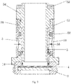
Fig. 1 is a sectional view of an atomization core inembodiment 1 of the present invention; -
Fig. 2 is an explosive view of an atomization core inembodiment 1 of the present invention; -
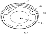
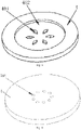
Fig.3 is a structural schematic diagram of an ultrasonic atomization piece corresponding toembodiment 1; -
Fig. 4 is a structure diagram of an atomizer of the atomization core corresponding toembodiment 1; -
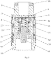
Fig. 5 is a sectional view of an atomization core inembodiment 2 of the present invention; -
Fig. 6 is a partial explosive view of an end cover and a first sleeve of the atomization core inembodiment 2 of the present invention; -
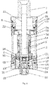
Fig. 7 is a structural schematic diagram of an atomizer inembodiment 2 of the present invention; -
Fig. 8 is a second structural schematic diagram of a second liquid guide body of the present invention; -
Fig. 9 is a second structural schematic diagram of the ultrasonic atomization piece of the present invention. -
Fig. 10 is a third structural schematic diagram of the ultrasonic atomization piece of the present invention. - A specific implementation process of the present invention will be illustrated below in combination with the drawings. The so-called top end below all refers to the end close to a suction nozzle of an atomizer, namely the end on an outflow direction of the atomizing gas; and so-called bottom end refers to the end opposite to the position of the top end.
- As shown in
Fig. 1 , atomization core inembodiment 1 of the present invention includes afirst sleeve 54 and asecond sleeve 55; anultrasonic atomization piece 1 is provided on one end of thesecond sleeve 55, the other end of thesecond sleeve 55 is in fixed connection with thefirst sleeve 54, a connecting end of thefirst sleeve 54 extends to the surface of theultrasonic atomization piece 1 and is not in contact with theultrasonic atomization piece 1; the part below a top end of thefirst sleeve 54 is provided in thesecond sleeve 55; a firstliquid guide body 3 is fixed between thefirst sleeve 54 and thesecond sleeve 55, one end of the firstliquid guide body 3 extends along the axial direction of thefirst sleeve 54 to contact with the surface of a secondliquid guide body 4; aliquid inlet hole 56 is provided in thesecond sleeve 55; and the secondliquid guide body 4 is in contact with theultrasonic atomization piece 1. - The
second sleeve 55 is provided in aliquid control ring 57; and an adjustinghole 58 is provided in theliquid control ring 57. - As shown in
Fig. 2 , the firstliquid guide body 3 is cylindrical tobacco tar guide cotton with two open ends and is sheathed on the first sleeve. The thickness of the side wall of a top end of the first sleeve is larger than the thickness of the side wall of the rest part (actually, aboss 51 is formed on an outer wall of the top end of the first sleeve), after thread below the boss at the top end of the second sleeve is in screw joint with the first sleeve, a liquid control ring (being a cylinder with two open ends actually) is sheathed at the outside of the second sleeve, the liquid control ring can be rotated, when the adjusting hole is overlapped with the liquid inlet hole, the liquid inlet volume is the largest, when the adjusting hole is stagger to the liquid inlet hole, the liquid inlet volume is reduced, and the liquid inlet hole is even closed. - A
silica gel piece 59 is provided on the first sleeve on one end, away from the liquid control ring, of theboss 51. - In order to prevent tobacco tar leakage of the atomization core, the liquid control ring is hermetically connected with the second sleeve through a
sealing ring 60. - The
ultrasonic atomization piece 1 is provided in amounting base 14, themounting base 14 is provided in a bottom part of thesecond sleeve 55, the firstliquid guide body 3 is fixed in themounting base 14, and the secondliquid guide body 4 and the firstliquid guide body 3 are sequentially arranged along an outflow direction of the atomizing gas. - The mounting base can be a silica gel base to buffer the oscillating force of the ultrasonic atomization piece, so as to prevent the damage of the ultrasonic atomization piece and prolong the service life of the ultrasonic atomization piece.
- As shown in
Fig. 3 , theultrasonic atomization piece 1 of the present invention includes a piezoelectric ceramicmain body 10; one surface of the piezoelectric ceramicmain body 10 is in contact with a positive electrode conductinglayer 11; and the other surface of the piezoelectric ceramicmain body 10 is in contact with a negative electrode conductinglayer 12, the negative electrode conductinglayer 12 extends to the surface of the piezoelectric ceramicmain body 10 on which the positive electrode conductinglayer 11 is located along a side edge of the piezoelectric ceramicmain body 10, and a plurality of convex point areas 13 (the edges of the convex points are circular arc-shaped) are provided on the edge of the negative electrode conductinglayer 12. The conducting layer can be set as a silver layer. - The structure of the atomization core of
embodiment 2 of the present invention is as shown inFig. 4 , in the embodiment, the part above the bottom end of thefirst sleeve 54 is provided in thesecond sleeve 55, themounting base 14 is provided in the bottom part of thesecond sleeve 55, the firstliquid guide body 3 is fixed in themounting base 14, and the secondliquid guide body 4 and the firstliquid guide body 3 are sequentially arranged along the outflow direction of the atomizing gas (i.e., the liquid is transferred reverse to the gravity direction). - In
embodiment 2, themounting base 14 is provided in the top part of thefirst sleeve 54; the secondliquid guide body 4 is provided on themounting base 14, and the side edge of the secondliquid guide body 4 stretches out from themounting base 14 and is in contact with the firstliquid guide body 3; the top end of thesecond sleeve 55 is connected with atop cover 9; and the firstliquid guide body 3 and the secondliquid guide body 4 are sequentially arranged along the outflow direction of the atomizing gas. - As shown in
Fig. 5 , inembodiment 2, theboss 51 is provided at the top end of the first sleeve, threads are provided on the first sleeves on both sides of the boss, the second sleeve is in screw joint with the first sleeve; and thetop cover 9 is in screw joint with the top end (i.e., the upper side of the boss) of the first sleeve. The interior of thetop cover 9 is of a hollow structure. Thesilica gel piece 59 is provided at the top end of thetop cover 9. - As shown in
Fig. 6 , in the atomizer corresponding toembodiment 1 of the present invention, aliquid storage cavity 2 is provided above theultrasonic atomization piece 1, and the upper part of the atomization core is provided in theliquid storage cavity 1; anairflow passage 5 of the atomizer includes anair outlet pipe 52 provided in thefirst sleeve 54; anair inlet passage 53 is provided between the inner wall of thefirst sleeve 54 and the outer wall of theair outlet pipe 52; the bottom end of theair outlet pipe 52 is communicated with an upper surface of the secondliquid guide body 4; the top end of theair outlet pipe 52 is in fixed connection with asuction nozzle base 6, and theair outlet pipe 52 is communicated with the inner cavity of asuction nozzle 7 on thesuction nozzle base 6; anair inlet 8 is provided in thesuction nozzle base 6; and theair inlet passage 53 is communicated with theair inlet 8 and the secondliquid guide body 4. - As shown in
Fig. 6 , thesilica gel piece 59 at the top end of the first sleeve is in contact with anair inlet ring 22; the outer wall of theair inlet ring 22 is in screw joint with the inner wall of anend cover 23; theend cover 23 is provided in anouter pipe 24; and the top end of theouter pipe 24 is connected with the bottom end of the suction nozzle base. Sealing rings are provided between theair inlet ring 22 and theend cover 23 and between the suction nozzle base and the outer pipe for sealing. - An
air adjusting ring 25 for adjusting the air flow amount on theair inlet 8 is further provided on the suction nozzle base, anair adjusting hole 26 is provided in theair adjusting ring 25, the air adjusting ring can be rotated, and when the position of the air adjusting hole is overlapped with the position of the air inlet, the air inflow amount is the largest. - The bottom end of the
second sleeve 55 is provided in the top part of theouter ring 15; a fixing ring 16 is provided in theouter ring 15; an insulatingring 17 is provided in the fixing ring 16; anegative electrode spring 18 is provided at the outside of the insulatingring 17; apositive electrode spring 19 is provided in the insulatingring 17; and thenegative electrode spring 18 is in contact with the negative electrode of theultrasonic atomization piece 1 through anegative electrode ring 20, and thepositive electrode spring 19 is in contact with the positive electrode of theultrasonic atomization piece 1 through apositive electrode ring 21. - The
outer ring 15 is provided in abase 57, and the top end of the base is in screw joint with the bottom end of theouter pipe 24 and seals the liquid storage cavity. Abottom plug 58 is provided on thebase 57, and the top end of thebottom plug 58 stretches into the insulatingring 17; anegative electrode spring 18 is provided at the outside of the insulatingring 17; apositive electrode spring 19 is provided in the insulatingring 17; thepositive electrode spring 19 is in contact with the top end of the bottom plug; and thenegative electrode spring 18 is in contact with the negative electrode of theultrasonic atomization piece 1 through anegative electrode ring 20, and thepositive electrode spring 19 is in contact with the positive electrode of theultrasonic atomization piece 1 through apositive electrode ring 21. The bottom end of thebottom plug 58 is in contact with anelectrode ring 27, and theelectrode ring 27 is provided in the inner part of the lower end of the base and is insulated from the base by an insulatingpart 28. - As shown in
Fig. 7 , when the atomization core inembodiment 2 is adopted, theairflow passage 5 includes theair outlet pipe 52 whose bottom end is provided in thetop cover 9; theair inlet passage 53 is provided between theair outlet pipe 52 and thetop cover 9; the bottom end of theair outlet pipe 52 is communicated with the upper surface of the secondliquid guide body 4; the top end of theair outlet pipe 52 is in fixed connection with thesuction nozzle base 6, and theair outlet pipe 52 is communicated with the inner cavity of thesuction nozzle 7 on thesuction nozzle base 6; theair inlet 8 is provided in thesuction nozzle base 6; and theair inlet passage 53 is communicated with theair inlet 8 and the secondliquid guide body 4. - The
top cover 9 is in contact with theair inlet ring 22; the outer wall of theair inlet ring 22 is in screw joint with the inner wall of theend cover 23; theend cover 23 is provided in theouter pipe 24; and the top end of theouter pipe 24 is connected with the bottom end of thesuction nozzle base 6. Sealing rings are provided between theair inlet ring 22 and theend cover 23 and between thesuction nozzle base 6 and the outer pipe for sealing. - A
bottom ring 29 is provided in thefirst sleeve 54; thebottom plug 58 is provided on thebottom ring 29, and the top end of thebottom plug 58 stretches into the insulatingring 17; thenegative electrode spring 18 is provided at the outside of the insulatingring 17; thepositive electrode spring 19 is provided in the insulatingring 17; and thenegative electrode spring 18 is in contact with the negative electrode of theultrasonic atomization piece 1 through anegative electrode ring 20, and thepositive electrode spring 19 is in contact with the positive electrode of theultrasonic atomization piece 1 through apositive electrode ring 21. - The bottom end of the
bottom plug 58 is in contact with theelectrode ring 27, theelectrode ring 27 is provided in the inner part of the lower end of the base and is insulated from the base by the insulatingpart 28, the top end of thebase 57 is in fixed connection with alower end cover 32, and thelower end cover 32 is connected with the bottom end of the outer pipe through a first fixing ring 30 and seals the liquid storage cavity. - One end of the
negative electrode spring 18 is in contact with thenegative electrode ring 20, and the other end of the negative electrode spring is in contact with asecond fixing ring 31 provided between the insulatingring 17 and thefirst sleeve 54. - As shown in
Fig. 8 , at least one throughhole 401 is provided in the secondliquid guide body 4. Adepression part 402 is provided at the middle of the secondliquid guide body 4, and the throughhole 401 is provided in thedepression part 402. As the liquid guide cotton at thedepression part 402 at the middle is thinner, the amount of the liquid absorbed by thedepression part 402 is smaller, and thus the problems that the atomization is overdue caused by excessive accumulated liquid, and that the start of theultrasonic atomization piece 1 is slow resulting from the fact that the secondliquid guide body 4 absorbs the heat on theultrasonic atomization piece 1 are solved. As shown inFig. 9 , at least one minipore 101 (theminipore 101 penetrates through the ultrasonic atomization piece 1) which is communicated with the throughhole 401 is provided in theultrasonic atomization piece 1, the aperture of theminipore 101 is about 0.1-200 microns, thereby guaranteeing that the liquid cannot pass by the minipore 101 and only the gas can pass by. - As shown in
Fig. 10 , a vent groove 102 (the surface provided with thevent groove 102 of theultrasonic atomization piece 1 is in contact with the second liquid guide body 4) is provided in the surface, opposite to the positiveelectrode conducting layer 11, of theultrasonic atomization piece 1, and thevent groove 102 is communicated with the throughhole 401. The airflow enters from thevent groove 102 and quickly takes away the atomizing gas on the surface of the secondliquid guide body 4, so that theultrasonic atomization piece 1 is started quickly, the atomizing gas is finer and smoother, and the particle sizes of the granules are more uniform. - Although the embodiments of the present invention have been described above in combination with the drawings, the present invention is not limited to the specific embodiments described above, and the specific embodiments described above are merely illustrative and are not restrictive.
Claims (14)
- An electronic cigarette atomization core, comprising an ultrasonic atomization piece (1) which comprises a piezoelectric ceramic main body (10); one surface of the piezoelectric ceramic main body (10) is in contact with a positive electrode conducting layer (11); and the other surface of the piezoelectric ceramic main body (10) is in contact with a negative electrode conducting layer (12), wherein the negative electrode conducting layer (12) extends to the surface of the piezoelectric ceramic main body (10) on which the positive electrode conducting layer (11) is located along a side edge of the piezoelectric ceramic main body (10), and a plurality of convex point areas (13) are provided on the edge of the negative electrode conducting layer (12).
- The electronic cigarette atomization core of claim 1, comprising a first sleeve (54), a second sleeve (55), a first liquid guide body (3) and a second liquid guide body (4); one end of the first sleeve (54) is provided in the second sleeve (55); the first liquid guide body (3) is fixed between the first sleeve (54) and the second sleeve (55), and one end of the first liquid guide body (3) is in contact with the second liquid guide body (4); a liquid inlet hole (56) is provided in the second sleeve (55), and the first liquid guide body (3) is communicated with the liquid inlet hole (56); and the second liquid guide body (4) is in contact with the ultrasonic atomization piece (1).
- The electronic cigarette atomization core of claim 2, wherein the second sleeve (55) is provided in a liquid control ring (57); and an adjusting hole (58) is provided in the liquid control ring (57).
- The electronic cigarette atomization core of claim 3, wherein the electronic cigarette atomization core further comprises a mounting base (14), the mounting base (14) is provided in a bottom part of the second sleeve (55), the first liquid guide body (3) is fixed in the mounting base (14), and the second liquid guide body (4) and the first liquid guide body (3) are sequentially arranged along an outflow direction of the atomizing gas.
- The electronic cigarette atomization core of claim 3, wherein the electronic cigarette atomization core further comprises a mounting base (14), the mounting base (14) is provided in a top part of the first sleeve (54); the second liquid guide body (4) is provided on the mounting base (14), and the side edge of the second liquid guide body (4) stretches out from the mounting base (14) and is in contact with the first liquid guide body (3) ; the top end of the second sleeve (55) is detachably connected with a top cover (9); and the first liquid guide body (3) and the second liquid guide body (4) are sequentially arranged along the outflow direction of the atomizing gas.
- The electronic cigarette atomization core of claim 2, wherein at least one through hole (401) is provided in the second liquid guide body (4).
- The electronic cigarette atomization core of claim 6, wherein at least one minipore (101) which penetrates through the ultrasonic atomization piece (1) is provided in the ultrasonic atomization piece (1).
- The electronic cigarette atomization core of claim 6, wherein a vent groove (102) is provided in the surface in which the ultrasonic atomization piece (1) is in contact with the second liquid guide body (4).
- The electronic cigarette atomization core of claim 6, wherein a depression part (402) is provided at the middle of the second liquid guide body (4), and the through hole (401) is provided in the depression part (402).
- An electronic cigarette atomizer, wherein the electronic cigarette atomizer comprises the electronic cigarette atomization core of claim 4 or 5, a liquid storage cavity (2) and an airflow passage (5); the liquid storage cavity (2) is communicated with the liquid inlet hole (56); and one surface, away from the ultrasonic atomization piece (1), of the second liquid guide body (4) is communicated with the airflow passage (5).
- The electronic cigarette atomizer of claim 10, wherein when the electronic cigarette atomization core of claim 5 is adopted, the airflow passage (5) comprises an air outlet pipe (52) provided in the first sleeve (54); an air inlet passage (53) is provided between an inner wall of the first sleeve (54) and an outer wall of the air outlet pipe (52); the bottom end of the air outlet pipe (52) is communicated with an upper surface of the second liquid guide body (4); the top end of the air outlet pipe (52) is in fixed connection with a suction nozzle base (6), and the air outlet pipe (52) is communicated with the inner cavity of a suction nozzle (7) on the suction nozzle base (6); an air inlet (8) is provided in the suction nozzle base (6); and the air inlet passage (53) is communicated with the air inlet (8) and the surface, away from the ultrasonic atomization piece (1), of the second liquid guide body (4).
- The electronic cigarette atomizer of claim 11, wherein the bottom end of the second sleeve (55) is provided in the top part of an outer ring (15); a second fixing ring (31) is provided in the outer ring (15); an insulating ring (17) is provided in the second fixing ring (31); a negative electrode spring (18) is provided at the outside of the insulating ring (17); a positive electrode spring (19) is provided in the insulating ring (17); and the negative electrode spring (18) is in contact with the negative electrode conducting layer (12) of the ultrasonic atomization piece (1) through a negative electrode ring (20), and the positive electrode spring (19) is in contact with the positive electrode conducting layer (11) of the ultrasonic atomization piece (1) through a positive electrode ring (21).
- The electronic cigarette atomizer of claim 10, wherein when the electronic cigarette atomization core of claim 6 is adopted, the airflow passage (5) comprises an air outlet pipe (52) whose bottom end is provided in the top cover (9); an air inlet passage (53) is provided between the air outlet pipe (52) and the top cover (9); the bottom end of the air outlet pipe (52) is communicated with the upper surface of the second liquid guide body (4); the top end of the air outlet pipe (52) is in fixed connection with a suction nozzle base (6), and the air outlet pipe (52) is communicated with the inner cavity of a suction nozzle (7) on the suction nozzle base (6); an air inlet (8) is formed in the suction nozzle base (6); and the air inlet passage (53) is communicated with the air inlet (8) and the second liquid guide body (4).
- The electronic cigarette atomizer of claim 13, wherein a base (57) is provided in the first sleeve (54); a bottom plug (58) is provided on the base (57), and the top end of the bottom plug (58) stretches into the insulating ring (17); a negative electrode spring (18) is provided at the outside of the insulating ring (17); a positive electrode spring (19) is provided in the insulating ring (17); and the negative electrode spring (18) is in contact with the negative electrode conducting layer (12) of the ultrasonic atomization piece (1) through a negative electrode ring (20), and the positive electrode spring (19) is in contact with the positive electrode conducting layer (11) of the ultrasonic atomization piece through a positive electrode ring (21).
Applications Claiming Priority (2)
| Application Number | Priority Date | Filing Date | Title |
|---|---|---|---|
| CN201620471233.4U CN205962833U (en) | 2016-05-23 | 2016-05-23 | Atomizing core and atomizer |
| PCT/CN2016/110583 WO2017202014A1 (en) | 2016-05-23 | 2016-12-17 | Ultrasonic atomizing sheet, and electronic cigarette atomizing core and atomizer |
Publications (3)
| Publication Number | Publication Date |
|---|---|
| EP3434118A1 EP3434118A1 (en) | 2019-01-30 |
| EP3434118A4 EP3434118A4 (en) | 2019-10-09 |
| EP3434118B1 true EP3434118B1 (en) | 2022-06-29 |
Family
ID=58019806
Family Applications (1)
| Application Number | Title | Priority Date | Filing Date |
|---|---|---|---|
| EP16902998.0A Active EP3434118B1 (en) | 2016-05-23 | 2016-12-17 | Ultrasonic atomizing sheet, and electronic cigarette atomizing core and atomizer |
Country Status (8)
| Country | Link |
|---|---|
| US (1) | US11039640B2 (en) |
| EP (1) | EP3434118B1 (en) |
| JP (1) | JP6735363B2 (en) |
| KR (1) | KR102176392B1 (en) |
| CN (1) | CN205962833U (en) |
| AU (1) | AU2016408199B2 (en) |
| ES (1) | ES2926680T3 (en) |
| WO (1) | WO2017202014A1 (en) |
Families Citing this family (59)
| Publication number | Priority date | Publication date | Assignee | Title |
|---|---|---|---|---|
| CN105559151B (en) * | 2016-03-21 | 2019-05-24 | 湖南中烟工业有限责任公司 | A kind of ultrasonic ultrasonic delay line memory and electronic cigarette |
| CN205912905U (en) * | 2016-08-03 | 2017-02-01 | 湖南中烟工业有限责任公司 | Ultrasonic wave electron smog core and atomizer |
| CN107752129B (en) * | 2016-08-19 | 2024-04-23 | 湖南中烟工业有限责任公司 | Ultrasonic atomization sheet and manufacturing method thereof, ultrasonic atomizer and electronic cigarette |
| EP3603427B1 (en) * | 2017-05-16 | 2023-03-29 | China Tobacco Hunan Industrial Co., Ltd. | Ultrasonic electronic cigarette atomizer and electronic cigarette using same |
| CN110662437B (en) | 2017-05-18 | 2022-09-23 | Jt国际股份公司 | Vaporizing unit of personal vaporizing device |
| US10349674B2 (en) | 2017-07-17 | 2019-07-16 | Rai Strategic Holdings, Inc. | No-heat, no-burn smoking article |
| WO2019052574A1 (en) * | 2017-09-18 | 2019-03-21 | 湖南中烟工业有限责任公司 | Atomizing core and atomizer of ultrasonic electronic cigarette |
| CN107927910A (en) * | 2017-11-13 | 2018-04-20 | 深圳市同牧科技有限公司 | A kind of interchangeable smoke grenade electronic smoke atomizer, smoke grenade component and atomizer assembly |
| CN109892697B (en) * | 2017-12-07 | 2024-08-02 | 湖南中烟工业有限责任公司 | Ultrasonic electronic cigarette atomization core and atomizer |
| US10729175B2 (en) * | 2018-03-02 | 2020-08-04 | Esquire Properties Trading Inc. | Vaporizer electrical system having a moving electrode with a combined electrical and airflow regulation function |
| CN108272142B (en) * | 2018-04-18 | 2023-10-17 | 深圳市优维尔科技有限公司 | Suction device with atomization function and electronic cigarette |
| CN110623301B (en) * | 2018-06-22 | 2024-06-04 | 湖南中烟工业有限责任公司 | Electron smog core and atomizer |
| CN108634387A (en) * | 2018-07-04 | 2018-10-12 | 深圳市至臻宝电子商务有限公司 | A kind of leakproof oil fogger |
| WO2020007321A1 (en) * | 2018-07-06 | 2020-01-09 | 湖南中烟工业有限责任公司 | Ultrasonic atomizing core, ultrasonic atomizer, and ultrasonic electronic cigarette |
| US20200077703A1 (en) * | 2018-09-11 | 2020-03-12 | Rai Strategic Holdings, Inc. | Wicking element for aerosol delivery device |
| EP3892136A4 (en) * | 2019-01-10 | 2021-12-22 | O-Net Automation Technology (Shenzhen) Limited | Atomization sheet for electronic cigarette and atomizer |
| US11096419B2 (en) | 2019-01-29 | 2021-08-24 | Rai Strategic Holdings, Inc. | Air pressure sensor for an aerosol delivery device |
| DE102019103990B4 (en) | 2019-02-18 | 2021-09-02 | Hauni Maschinenbau Gmbh | Vaporizer insert for an inhaler, in particular an electronic cigarette product, vaporizer-tank unit and an electronic cigarette product |
| US12396480B2 (en) | 2019-05-22 | 2025-08-26 | Rai Strategic Holdings, Inc. | Reservoir configuration for aerosol delivery device |
| EP4559330A3 (en) * | 2019-06-20 | 2025-08-20 | Shaheen Innovations Holding Limited | Personal ultrasonic atomizer device |
| US11207711B2 (en) | 2019-08-19 | 2021-12-28 | Rai Strategic Holdings, Inc. | Detachable atomization assembly for aerosol delivery device |
| WO2021036827A1 (en) * | 2019-08-30 | 2021-03-04 | 湖南中烟工业有限责任公司 | Electronic cigarette atomization core and atomizer |
| CN112438439B (en) * | 2019-08-30 | 2021-10-26 | 湖南中烟工业有限责任公司 | Electronic cigarette atomizing core and atomizer |
| US11889861B2 (en) | 2019-09-23 | 2024-02-06 | Rai Strategic Holdings, Inc. | Arrangement of atomization assemblies for aerosol delivery device |
| US11785991B2 (en) | 2019-10-04 | 2023-10-17 | Rai Strategic Holdings, Inc. | Use of infrared temperature detection in an aerosol delivery device |
| US12414586B2 (en) | 2019-10-18 | 2025-09-16 | Rai Strategic Holdings, Inc. | Surface acoustic wave atomizer for aerosol delivery device |
| US11304451B2 (en) | 2019-10-18 | 2022-04-19 | Rai Strategic Holdings, Inc. | Aerosol delivery device with dual reservoir |
| KR102385875B1 (en) * | 2019-11-27 | 2022-04-13 | 김선혜 | Electronic Cigarette |
| US11744963B2 (en) | 2019-12-15 | 2023-09-05 | Shaheen Innovations Holding Limited | Mist inhaler devices |
| ES3028096T3 (en) | 2019-12-15 | 2025-06-18 | Shaheen Innovations Holding Ltd | Ultrasonic mist inhaler |
| US12262738B2 (en) | 2019-12-15 | 2025-04-01 | Shaheen Innovations Holding Limited | Ultrasonic mist inhaler |
| US11730193B2 (en) | 2019-12-15 | 2023-08-22 | Shaheen Innovations Holding Limited | Hookah device |
| EP3860696B1 (en) | 2019-12-15 | 2024-04-10 | Shaheen Innovations Holding Limited | Ultrasonic mist inhaler |
| US11666713B2 (en) | 2019-12-15 | 2023-06-06 | Shaheen Innovations Holding Limited | Mist inhaler devices |
| WO2021123866A1 (en) | 2019-12-15 | 2021-06-24 | Shaheen Innovations Holding Limited | Ultrasonic mist inhaler |
| EP3856304B1 (en) | 2019-12-15 | 2023-11-08 | Shaheen Innovations Holding Limited | Ultrasonic mist inhaler |
| US11589610B2 (en) | 2019-12-15 | 2023-02-28 | Shaheen Innovations Holding Limited | Nicotine delivery device having a mist generator device and a driver device |
| IL294000B (en) | 2019-12-15 | 2022-09-01 | Shaheen Innovations Holding Ltd | Mist inhaler devices |
| US11730191B2 (en) | 2019-12-15 | 2023-08-22 | Shaheen Innovations Holding Limited | Hookah device |
| US11602165B2 (en) | 2019-12-15 | 2023-03-14 | Shaheen Innovations Holding Limited | Nicotine delivery device having a mist generator device and a driver device |
| US11819607B2 (en) | 2019-12-15 | 2023-11-21 | Shaheen Innovations Holding Limited | Mist inhaler devices |
| WO2021121356A1 (en) * | 2019-12-20 | 2021-06-24 | 湖南中烟工业有限责任公司 | Ultrasonic atomizer and oil-guide ceramic |
| US12687470B2 (en) | 2020-04-06 | 2026-07-21 | Shaheen Innovations Holding Limited | Cell lysis systems and methods |
| IL298682B2 (en) | 2020-06-01 | 2026-02-01 | Shaheen Innovations Holding Ltd | An infectious disease screening device |
| AU2021285405B2 (en) | 2020-06-01 | 2026-06-18 | Shaheen Innovations Holding Limited | An infectious disease screening system |
| KR102449809B1 (en) | 2020-06-05 | 2022-09-30 | 주식회사 케이티앤지 | Cartridge and aerosol generating device comprising same |
| US11969545B2 (en) | 2020-12-01 | 2024-04-30 | Rai Strategic Holdings, Inc. | Liquid feed systems for an aerosol delivery device |
| CN115023154B (en) | 2020-12-03 | 2025-04-18 | 韩国烟草人参公社 | Atomization assembly, cigarette cartridge, and aerosol generating device including the cigarette cartridge |
| KR102523578B1 (en) * | 2020-12-04 | 2023-04-20 | 주식회사 케이티앤지 | Aerosol generating device |
| CN112439633B (en) * | 2020-12-04 | 2021-12-10 | 广州大学 | Atomization device |
| EP4087426A4 (en) * | 2020-12-04 | 2023-06-21 | KT&G Corporation | AEROSOL GENERATION DEVICE |
| JP7886873B2 (en) * | 2020-12-23 | 2026-07-08 | フィリップ・モーリス・プロダクツ・ソシエテ・アノニム | Aerosol generation system equipped with transducer |
| CN114176255A (en) * | 2021-11-02 | 2022-03-15 | 深圳爱芯怡科技有限公司 | Atomizing core and atomizing device |
| CN116235994A (en) * | 2021-12-07 | 2023-06-09 | 深圳市合元科技有限公司 | Ultrasonic atomization component, ultrasonic atomizer and ultrasonic atomization device |
| US20230188901A1 (en) | 2021-12-15 | 2023-06-15 | Shaheen Innovations Holding Limited | Apparatus for transmitting ultrasonic waves |
| US20250089770A1 (en) * | 2022-06-23 | 2025-03-20 | Kt & G Corporation | Cartridge for aerosol generating device |
| US12550948B2 (en) | 2022-08-19 | 2026-02-17 | Rai Strategic Holdings, Inc. | Pressurized aerosol delivery device |
| CN115534493B (en) * | 2022-10-20 | 2024-06-21 | 深圳市尚进电子科技有限公司 | Micro-grid atomizing sheet based on FPC flexible circuit board and manufacturing process thereof |
| WO2026033196A1 (en) * | 2024-08-05 | 2026-02-12 | Shaheen Innovations Holding Limited | Mist inhalation pod for delivering a therapeutic |
Family Cites Families (11)
| Publication number | Priority date | Publication date | Assignee | Title |
|---|---|---|---|---|
| JPH05236596A (en) * | 1992-02-18 | 1993-09-10 | A & D Co Ltd | Ultrasonic transducer |
| CN1029511C (en) * | 1993-03-16 | 1995-08-16 | 咸寿荣 | Nickel electrode ultrasonic atomization piezoelectric transducer and manufacturing process thereof |
| US6196218B1 (en) * | 1999-02-24 | 2001-03-06 | Ponwell Enterprises Ltd | Piezo inhaler |
| CN2912831Y (en) * | 2006-06-16 | 2007-06-20 | 任祖其 | Ultrasound piezoelectricity atomization slice with lug adhesive membrane |
| JP2008207055A (en) * | 2007-02-23 | 2008-09-11 | Mitsubishi Electric Corp | Ultrasonic atomizer and equipment equipped with the same |
| JP5395423B2 (en) * | 2008-12-19 | 2014-01-22 | 花王株式会社 | Ultrasonic atomizer |
| CN203448228U (en) * | 2013-08-20 | 2014-02-26 | 褚军 | Ultrasonic atomization piece |
| CN104368484B (en) * | 2014-11-14 | 2016-10-05 | 深圳麦克韦尔股份有限公司 | Inhalator and atomizing component thereof |
| US20170119040A1 (en) * | 2015-10-30 | 2017-05-04 | Lunatech, Llc | Water-based vaporizable liquids, methods and systems for vaporizing same |
| CN105559151B (en) * | 2016-03-21 | 2019-05-24 | 湖南中烟工业有限责任公司 | A kind of ultrasonic ultrasonic delay line memory and electronic cigarette |
| CA3013531C (en) * | 2016-03-30 | 2024-05-28 | Philip Morris Products S.A. | Smoking device and method for aerosol-generation |
-
2016
- 2016-05-23 CN CN201620471233.4U patent/CN205962833U/en not_active Expired - Lifetime
- 2016-12-17 KR KR1020187032591A patent/KR102176392B1/en active Active
- 2016-12-17 AU AU2016408199A patent/AU2016408199B2/en active Active
- 2016-12-17 WO PCT/CN2016/110583 patent/WO2017202014A1/en not_active Ceased
- 2016-12-17 JP JP2018560800A patent/JP6735363B2/en active Active
- 2016-12-17 ES ES16902998T patent/ES2926680T3/en active Active
- 2016-12-17 US US16/300,130 patent/US11039640B2/en active Active
- 2016-12-17 EP EP16902998.0A patent/EP3434118B1/en active Active
Also Published As
| Publication number | Publication date |
|---|---|
| US20190142063A1 (en) | 2019-05-16 |
| CN205962833U (en) | 2017-02-22 |
| KR20180129929A (en) | 2018-12-05 |
| EP3434118A1 (en) | 2019-01-30 |
| JP2019518451A (en) | 2019-07-04 |
| KR102176392B1 (en) | 2020-11-09 |
| US11039640B2 (en) | 2021-06-22 |
| AU2016408199B2 (en) | 2020-06-11 |
| AU2016408199A1 (en) | 2018-11-22 |
| WO2017202014A1 (en) | 2017-11-30 |
| EP3434118A4 (en) | 2019-10-09 |
| ES2926680T3 (en) | 2022-10-27 |
| JP6735363B2 (en) | 2020-08-05 |
Similar Documents
| Publication | Publication Date | Title |
|---|---|---|
| US11039640B2 (en) | Ultrasonic atomization piece, electronic cigarette atomization core and electronic cigarette atomizer | |
| CN205757215U (en) | Heating wire atomization is atomized, with piezoelectric ceramics, the electronic smoke atomizer being arranged in parallel | |
| EP3597056A1 (en) | Ultrasonic electronic cigarette atomizer | |
| KR102180389B1 (en) | Electronic cigarette atomizer | |
| US20180161525A1 (en) | Ultrasonic atomizer and electronic cigarette | |
| US20240207479A1 (en) | Fragrance machine | |
| CN106793832B (en) | an electronic cigarette | |
| CN105768238B (en) | A kind of ultrasonic ultrasonic delay line memory and electronic cigarette | |
| WO2018058883A1 (en) | Ultrasonic atomizer for electronic cigarette | |
| EP2837297B1 (en) | Atomizer and electronic cigarette having same | |
| US20210076733A1 (en) | Ultrasonic electronic cigarette atomizer and electronic cigarette | |
| EP3593655A1 (en) | Ultrasonic atomization type electronic cigarette | |
| EP3469933A1 (en) | Disposable cigarette cartridge, atomizer, and electronic cigarette | |
| CN108201175B (en) | Atomizing core, preparation method, atomizer, and electronic cigarette | |
| WO2018032672A1 (en) | Atomizer and electronic cigarette comprising same | |
| WO2019011222A1 (en) | Atomizer and electronic cigarette having same | |
| JP2019521677A (en) | Cotton-free ultrasonic atomizer and electronic cigarette | |
| WO2012129787A1 (en) | Electronic cigarette | |
| WO2016000201A1 (en) | Electronic cigarette heating assembly | |
| CN105982364A (en) | Atomizer and electronic cigarette | |
| CN206240711U (en) | A kind of ultrasonic ultrasonic delay line memory | |
| US20210315059A1 (en) | Heating core assembly of atomizer and electronic cigarette comprising same | |
| CN108618204A (en) | Atomizer and electronic cigarette | |
| CN202015670U (en) | Ultrasonic atomizer | |
| WO2024098543A1 (en) | Heating assembly applicable to porous liquid guide body, and atomizer |
Legal Events
| Date | Code | Title | Description |
|---|---|---|---|
| STAA | Information on the status of an ep patent application or granted ep patent |
Free format text: STATUS: THE INTERNATIONAL PUBLICATION HAS BEEN MADE |
|
| PUAI | Public reference made under article 153(3) epc to a published international application that has entered the european phase |
Free format text: ORIGINAL CODE: 0009012 |
|
| STAA | Information on the status of an ep patent application or granted ep patent |
Free format text: STATUS: REQUEST FOR EXAMINATION WAS MADE |
|
| 17P | Request for examination filed |
Effective date: 20181023 |
|
| AK | Designated contracting states |
Kind code of ref document: A1 Designated state(s): AL AT BE BG CH CY CZ DE DK EE ES FI FR GB GR HR HU IE IS IT LI LT LU LV MC MK MT NL NO PL PT RO RS SE SI SK SM TR |
|
| AX | Request for extension of the european patent |
Extension state: BA ME |
|
| DAV | Request for validation of the european patent (deleted) | ||
| DAX | Request for extension of the european patent (deleted) | ||
| A4 | Supplementary search report drawn up and despatched |
Effective date: 20190911 |
|
| RIC1 | Information provided on ipc code assigned before grant |
Ipc: B05B 17/06 20060101ALI20190905BHEP Ipc: A24F 47/00 20060101AFI20190905BHEP |
|
| REG | Reference to a national code |
Ref country code: DE Ref legal event code: R079 Ref document number: 602016073244 Country of ref document: DE Free format text: PREVIOUS MAIN CLASS: A24F0047000000 Ipc: A24F0040050000 |
|
| GRAP | Despatch of communication of intention to grant a patent |
Free format text: ORIGINAL CODE: EPIDOSNIGR1 |
|
| STAA | Information on the status of an ep patent application or granted ep patent |
Free format text: STATUS: GRANT OF PATENT IS INTENDED |
|
| RIC1 | Information provided on ipc code assigned before grant |
Ipc: B05B 17/06 20060101ALI20220407BHEP Ipc: A24F 40/485 20200101ALI20220407BHEP Ipc: A24F 40/44 20200101ALI20220407BHEP Ipc: A24F 40/05 20200101AFI20220407BHEP |
|
| INTG | Intention to grant announced |
Effective date: 20220421 |
|
| GRAS | Grant fee paid |
Free format text: ORIGINAL CODE: EPIDOSNIGR3 |
|
| GRAA | (expected) grant |
Free format text: ORIGINAL CODE: 0009210 |
|
| STAA | Information on the status of an ep patent application or granted ep patent |
Free format text: STATUS: THE PATENT HAS BEEN GRANTED |
|
| AK | Designated contracting states |
Kind code of ref document: B1 Designated state(s): AL AT BE BG CH CY CZ DE DK EE ES FI FR GB GR HR HU IE IS IT LI LT LU LV MC MK MT NL NO PL PT RO RS SE SI SK SM TR |
|
| REG | Reference to a national code |
Ref country code: CH Ref legal event code: EP |
|
| REG | Reference to a national code |
Ref country code: DE Ref legal event code: R096 Ref document number: 602016073244 Country of ref document: DE |
|
| REG | Reference to a national code |
Ref country code: AT Ref legal event code: REF Ref document number: 1500687 Country of ref document: AT Kind code of ref document: T Effective date: 20220715 |
|
| REG | Reference to a national code |
Ref country code: IE Ref legal event code: FG4D |
|
| REG | Reference to a national code |
Ref country code: LT Ref legal event code: MG9D |
|
| REG | Reference to a national code |
Ref country code: ES Ref legal event code: FG2A Ref document number: 2926680 Country of ref document: ES Kind code of ref document: T3 Effective date: 20221027 |
|
| PG25 | Lapsed in a contracting state [announced via postgrant information from national office to epo] |
Ref country code: SE Free format text: LAPSE BECAUSE OF FAILURE TO SUBMIT A TRANSLATION OF THE DESCRIPTION OR TO PAY THE FEE WITHIN THE PRESCRIBED TIME-LIMIT Effective date: 20220629 Ref country code: NO Free format text: LAPSE BECAUSE OF FAILURE TO SUBMIT A TRANSLATION OF THE DESCRIPTION OR TO PAY THE FEE WITHIN THE PRESCRIBED TIME-LIMIT Effective date: 20220929 Ref country code: LT Free format text: LAPSE BECAUSE OF FAILURE TO SUBMIT A TRANSLATION OF THE DESCRIPTION OR TO PAY THE FEE WITHIN THE PRESCRIBED TIME-LIMIT Effective date: 20220629 Ref country code: HR Free format text: LAPSE BECAUSE OF FAILURE TO SUBMIT A TRANSLATION OF THE DESCRIPTION OR TO PAY THE FEE WITHIN THE PRESCRIBED TIME-LIMIT Effective date: 20220629 Ref country code: GR Free format text: LAPSE BECAUSE OF FAILURE TO SUBMIT A TRANSLATION OF THE DESCRIPTION OR TO PAY THE FEE WITHIN THE PRESCRIBED TIME-LIMIT Effective date: 20220930 Ref country code: FI Free format text: LAPSE BECAUSE OF FAILURE TO SUBMIT A TRANSLATION OF THE DESCRIPTION OR TO PAY THE FEE WITHIN THE PRESCRIBED TIME-LIMIT Effective date: 20220629 Ref country code: BG Free format text: LAPSE BECAUSE OF FAILURE TO SUBMIT A TRANSLATION OF THE DESCRIPTION OR TO PAY THE FEE WITHIN THE PRESCRIBED TIME-LIMIT Effective date: 20220929 |
|
| REG | Reference to a national code |
Ref country code: NL Ref legal event code: MP Effective date: 20220629 |
|
| REG | Reference to a national code |
Ref country code: AT Ref legal event code: MK05 Ref document number: 1500687 Country of ref document: AT Kind code of ref document: T Effective date: 20220629 |
|
| PG25 | Lapsed in a contracting state [announced via postgrant information from national office to epo] |
Ref country code: RS Free format text: LAPSE BECAUSE OF FAILURE TO SUBMIT A TRANSLATION OF THE DESCRIPTION OR TO PAY THE FEE WITHIN THE PRESCRIBED TIME-LIMIT Effective date: 20220629 Ref country code: LV Free format text: LAPSE BECAUSE OF FAILURE TO SUBMIT A TRANSLATION OF THE DESCRIPTION OR TO PAY THE FEE WITHIN THE PRESCRIBED TIME-LIMIT Effective date: 20220629 |
|
| PG25 | Lapsed in a contracting state [announced via postgrant information from national office to epo] |
Ref country code: NL Free format text: LAPSE BECAUSE OF FAILURE TO SUBMIT A TRANSLATION OF THE DESCRIPTION OR TO PAY THE FEE WITHIN THE PRESCRIBED TIME-LIMIT Effective date: 20220629 |
|
| PG25 | Lapsed in a contracting state [announced via postgrant information from national office to epo] |
Ref country code: SM Free format text: LAPSE BECAUSE OF FAILURE TO SUBMIT A TRANSLATION OF THE DESCRIPTION OR TO PAY THE FEE WITHIN THE PRESCRIBED TIME-LIMIT Effective date: 20220629 Ref country code: SK Free format text: LAPSE BECAUSE OF FAILURE TO SUBMIT A TRANSLATION OF THE DESCRIPTION OR TO PAY THE FEE WITHIN THE PRESCRIBED TIME-LIMIT Effective date: 20220629 Ref country code: RO Free format text: LAPSE BECAUSE OF FAILURE TO SUBMIT A TRANSLATION OF THE DESCRIPTION OR TO PAY THE FEE WITHIN THE PRESCRIBED TIME-LIMIT Effective date: 20220629 Ref country code: PT Free format text: LAPSE BECAUSE OF FAILURE TO SUBMIT A TRANSLATION OF THE DESCRIPTION OR TO PAY THE FEE WITHIN THE PRESCRIBED TIME-LIMIT Effective date: 20221031 Ref country code: EE Free format text: LAPSE BECAUSE OF FAILURE TO SUBMIT A TRANSLATION OF THE DESCRIPTION OR TO PAY THE FEE WITHIN THE PRESCRIBED TIME-LIMIT Effective date: 20220629 Ref country code: AT Free format text: LAPSE BECAUSE OF FAILURE TO SUBMIT A TRANSLATION OF THE DESCRIPTION OR TO PAY THE FEE WITHIN THE PRESCRIBED TIME-LIMIT Effective date: 20220629 |
|
| PG25 | Lapsed in a contracting state [announced via postgrant information from national office to epo] |
Ref country code: PL Free format text: LAPSE BECAUSE OF FAILURE TO SUBMIT A TRANSLATION OF THE DESCRIPTION OR TO PAY THE FEE WITHIN THE PRESCRIBED TIME-LIMIT Effective date: 20220629 Ref country code: IS Free format text: LAPSE BECAUSE OF FAILURE TO SUBMIT A TRANSLATION OF THE DESCRIPTION OR TO PAY THE FEE WITHIN THE PRESCRIBED TIME-LIMIT Effective date: 20221029 |
|
| REG | Reference to a national code |
Ref country code: DE Ref legal event code: R097 Ref document number: 602016073244 Country of ref document: DE |
|
| PG25 | Lapsed in a contracting state [announced via postgrant information from national office to epo] |
Ref country code: AL Free format text: LAPSE BECAUSE OF FAILURE TO SUBMIT A TRANSLATION OF THE DESCRIPTION OR TO PAY THE FEE WITHIN THE PRESCRIBED TIME-LIMIT Effective date: 20220629 |
|
| PG25 | Lapsed in a contracting state [announced via postgrant information from national office to epo] |
Ref country code: DK Free format text: LAPSE BECAUSE OF FAILURE TO SUBMIT A TRANSLATION OF THE DESCRIPTION OR TO PAY THE FEE WITHIN THE PRESCRIBED TIME-LIMIT Effective date: 20220629 Ref country code: CZ Free format text: LAPSE BECAUSE OF FAILURE TO SUBMIT A TRANSLATION OF THE DESCRIPTION OR TO PAY THE FEE WITHIN THE PRESCRIBED TIME-LIMIT Effective date: 20220629 |
|
| PLBE | No opposition filed within time limit |
Free format text: ORIGINAL CODE: 0009261 |
|
| STAA | Information on the status of an ep patent application or granted ep patent |
Free format text: STATUS: NO OPPOSITION FILED WITHIN TIME LIMIT |
|
| 26N | No opposition filed |
Effective date: 20230330 |
|
| REG | Reference to a national code |
Ref country code: CH Ref legal event code: PL |
|
| REG | Reference to a national code |
Ref country code: DE Ref legal event code: R082 Ref document number: 602016073244 Country of ref document: DE Representative=s name: ALPSPITZ IP ALLGAYER UND PARTNER PATENTANWAELT, DE |
|
| REG | Reference to a national code |
Ref country code: BE Ref legal event code: MM Effective date: 20221231 |
|
| PG25 | Lapsed in a contracting state [announced via postgrant information from national office to epo] |
Ref country code: SI Free format text: LAPSE BECAUSE OF FAILURE TO SUBMIT A TRANSLATION OF THE DESCRIPTION OR TO PAY THE FEE WITHIN THE PRESCRIBED TIME-LIMIT Effective date: 20220629 Ref country code: LU Free format text: LAPSE BECAUSE OF NON-PAYMENT OF DUE FEES Effective date: 20221217 |
|
| PG25 | Lapsed in a contracting state [announced via postgrant information from national office to epo] |
Ref country code: LI Free format text: LAPSE BECAUSE OF NON-PAYMENT OF DUE FEES Effective date: 20221231 Ref country code: IE Free format text: LAPSE BECAUSE OF NON-PAYMENT OF DUE FEES Effective date: 20221217 Ref country code: CH Free format text: LAPSE BECAUSE OF NON-PAYMENT OF DUE FEES Effective date: 20221231 |
|
| PG25 | Lapsed in a contracting state [announced via postgrant information from national office to epo] |
Ref country code: BE Free format text: LAPSE BECAUSE OF NON-PAYMENT OF DUE FEES Effective date: 20221231 |
|
| PG25 | Lapsed in a contracting state [announced via postgrant information from national office to epo] |
Ref country code: HU Free format text: LAPSE BECAUSE OF FAILURE TO SUBMIT A TRANSLATION OF THE DESCRIPTION OR TO PAY THE FEE WITHIN THE PRESCRIBED TIME-LIMIT; INVALID AB INITIO Effective date: 20161217 |
|
| PG25 | Lapsed in a contracting state [announced via postgrant information from national office to epo] |
Ref country code: CY Free format text: LAPSE BECAUSE OF FAILURE TO SUBMIT A TRANSLATION OF THE DESCRIPTION OR TO PAY THE FEE WITHIN THE PRESCRIBED TIME-LIMIT Effective date: 20220629 |
|
| PG25 | Lapsed in a contracting state [announced via postgrant information from national office to epo] |
Ref country code: MK Free format text: LAPSE BECAUSE OF FAILURE TO SUBMIT A TRANSLATION OF THE DESCRIPTION OR TO PAY THE FEE WITHIN THE PRESCRIBED TIME-LIMIT Effective date: 20220629 |
|
| PG25 | Lapsed in a contracting state [announced via postgrant information from national office to epo] |
Ref country code: MC Free format text: LAPSE BECAUSE OF FAILURE TO SUBMIT A TRANSLATION OF THE DESCRIPTION OR TO PAY THE FEE WITHIN THE PRESCRIBED TIME-LIMIT Effective date: 20220629 |
|
| PG25 | Lapsed in a contracting state [announced via postgrant information from national office to epo] |
Ref country code: MC Free format text: LAPSE BECAUSE OF FAILURE TO SUBMIT A TRANSLATION OF THE DESCRIPTION OR TO PAY THE FEE WITHIN THE PRESCRIBED TIME-LIMIT Effective date: 20220629 |
|
| PG25 | Lapsed in a contracting state [announced via postgrant information from national office to epo] |
Ref country code: MT Free format text: LAPSE BECAUSE OF FAILURE TO SUBMIT A TRANSLATION OF THE DESCRIPTION OR TO PAY THE FEE WITHIN THE PRESCRIBED TIME-LIMIT Effective date: 20220629 |
|
| PG25 | Lapsed in a contracting state [announced via postgrant information from national office to epo] |
Ref country code: BG Free format text: LAPSE BECAUSE OF FAILURE TO SUBMIT A TRANSLATION OF THE DESCRIPTION OR TO PAY THE FEE WITHIN THE PRESCRIBED TIME-LIMIT Effective date: 20220629 |
|
| PG25 | Lapsed in a contracting state [announced via postgrant information from national office to epo] |
Ref country code: BG Free format text: LAPSE BECAUSE OF FAILURE TO SUBMIT A TRANSLATION OF THE DESCRIPTION OR TO PAY THE FEE WITHIN THE PRESCRIBED TIME-LIMIT Effective date: 20220629 |
|
| PG25 | Lapsed in a contracting state [announced via postgrant information from national office to epo] |
Ref country code: TR Free format text: LAPSE BECAUSE OF FAILURE TO SUBMIT A TRANSLATION OF THE DESCRIPTION OR TO PAY THE FEE WITHIN THE PRESCRIBED TIME-LIMIT Effective date: 20220629 |
|
| PGFP | Annual fee paid to national office [announced via postgrant information from national office to epo] |
Ref country code: GB Payment date: 20251229 Year of fee payment: 10 |
|
| PGFP | Annual fee paid to national office [announced via postgrant information from national office to epo] |
Ref country code: IT Payment date: 20251210 Year of fee payment: 10 |
|
| PGFP | Annual fee paid to national office [announced via postgrant information from national office to epo] |
Ref country code: FR Payment date: 20251230 Year of fee payment: 10 |
|
| PGFP | Annual fee paid to national office [announced via postgrant information from national office to epo] |
Ref country code: ES Payment date: 20260112 Year of fee payment: 10 |
|
| PGFP | Annual fee paid to national office [announced via postgrant information from national office to epo] |
Ref country code: DE Payment date: 20251231 Year of fee payment: 10 |