EP3433944B1 - Verfahren und vorrichtung zur auswahl von antennenstrahlformungsvorcodierungsvektoren für übertragungen - Google Patents
Verfahren und vorrichtung zur auswahl von antennenstrahlformungsvorcodierungsvektoren für übertragungen Download PDFInfo
- Publication number
- EP3433944B1 EP3433944B1 EP16711681.3A EP16711681A EP3433944B1 EP 3433944 B1 EP3433944 B1 EP 3433944B1 EP 16711681 A EP16711681 A EP 16711681A EP 3433944 B1 EP3433944 B1 EP 3433944B1
- Authority
- EP
- European Patent Office
- Prior art keywords
- time
- transmitting
- receiving device
- threshold
- forming precoding
- Prior art date
- Legal status (The legal status is an assumption and is not a legal conclusion. Google has not performed a legal analysis and makes no representation as to the accuracy of the status listed.)
- Active
Links
Images


Classifications
-
- H—ELECTRICITY
- H04—ELECTRIC COMMUNICATION TECHNIQUE
- H04B—TRANSMISSION
- H04B7/00—Radio transmission systems, i.e. using radiation field
- H04B7/02—Diversity systems; Multi-antenna system, i.e. transmission or reception using multiple antennas
- H04B7/04—Diversity systems; Multi-antenna system, i.e. transmission or reception using multiple antennas using two or more spaced independent antennas
- H04B7/06—Diversity systems; Multi-antenna system, i.e. transmission or reception using multiple antennas using two or more spaced independent antennas at the transmitting station
- H04B7/0686—Hybrid systems, i.e. switching and simultaneous transmission
- H04B7/0691—Hybrid systems, i.e. switching and simultaneous transmission using subgroups of transmit antennas
-
- H—ELECTRICITY
- H04—ELECTRIC COMMUNICATION TECHNIQUE
- H04B—TRANSMISSION
- H04B7/00—Radio transmission systems, i.e. using radiation field
- H04B7/02—Diversity systems; Multi-antenna system, i.e. transmission or reception using multiple antennas
- H04B7/04—Diversity systems; Multi-antenna system, i.e. transmission or reception using multiple antennas using two or more spaced independent antennas
- H04B7/06—Diversity systems; Multi-antenna system, i.e. transmission or reception using multiple antennas using two or more spaced independent antennas at the transmitting station
- H04B7/0686—Hybrid systems, i.e. switching and simultaneous transmission
- H04B7/0689—Hybrid systems, i.e. switching and simultaneous transmission using different transmission schemes, at least one of them being a diversity transmission scheme
Definitions
- the present invention relates to a method, in a transmitting device having a plurality of transmitter antennas, for selecting antenna beam-forming precoding vectors for transmissions.
- the present invention further relates to a transmitter device having a plurality of transmitter antennas.
- the radio links have a Downlink, DL, and an Uplink, UL.
- the Downlink is a transmission from a "master” node such as a base station (eNB) to a "slave” node such as a User Equipment, UE.
- the Uplink is a transmission from the "slave" node to the "master node”.
- a downlink transmission may schedule an Uplink transmission on the radio link from the "slave” node.
- the DL transmit power is a fixed power density according to a maximum power.
- the UL transmit power is determined by the slave node, based on measurements of a downlink reference signal received from the master node. The aim is that all UL transmissions are received at the master node at more or less the same power.
- P PUSCH i min P CMAX , 10 log 10 M PUSCH i + P O _ PUSCH j + ⁇ j ⁇ PL + ⁇ TF i + f i
- P CMAX ( i ) is the configured maximum UE transmit power
- M PUSCH ( i ) is the number of resource block allocated for the UE
- P O_PUSCH ( j ) is a parameter consisting of the sum of a cell-specific and a UE-specific part provided by higher layers
- ⁇ is a cell-specific parameter configured by higher layers (also known as fractional pathloss compensation factor)
- PL is the downlink pathloss estimate calculated by the UE
- ⁇ TF ( i ) is a UE-specific parameter provided by higher layers
- f ( i ) is
- Antenna beamforming is a signal processing technique whereby, in a transmitting device comprising a plurality of transmit antennas, a signal to be transmitted is mapped to the plurality of transmit antennas so as to increase the power of the signal received at the receiving device.
- a transmitting device for example a UE, may calculate a beamforming precoding vector for a transmission, based on measurements of reference signals received from the receiving device, for example using SVD (Single Value Decomposition).
- beamforming may not be necessary. However, at higher frequencies, such as those likely to be used in future wireless systems, beamforming is expected to be required.
- DTX inactive times are effectively periods, in which the UE is in "sleep mode", and so does not transmit and or receive transmissions. This enables low power consumption, which is advantageous for many for example machine type applications.
- these inactive periods make uplink beamforming difficult, since the decorrelation time of a beamforming precoding vector may be shorter than the DTX and/or DRX period, during which no reference signals are available for beamforming calculations.
- the DTX/DRX reference signal non-availability duration is a maximum of 5ms. It is expected that in 5G, the DTX/DRX reference signal non-availability duration will be up to 100ms.
- EP2862325 A1 discloses a transmitting node artificially creates a randomization of the precoders applied to the transmitted signal in the event that reliable channel state information is unavailable.
- Different precoding vectors are applied to both transmitted data and demodulation reference signals for each of several groups of time-frequency resources, where the precoding vectors vary randomly or pseudo-randomly from each group of time-frequency resources to the next frequency-adjacent group or groups, or to the next time-adjacent group or groups, or both.
- a method in a transmitting device having a plurality of transmitter antennas, for selecting antenna beam-forming precoding vectors for transmissions.
- the method comprises transmitting to a receiving device at a first time, using a first beam-forming precoding vector that maps symbols to be transmitted to the plurality of transmitter antennas.
- the method further comprises determining, prior to transmitting to the receiving device at a second time, whether an elapsed time since the first time exceeds a first threshold.
- the method further comprises selecting one of at least two beam-forming precoding vectors for use in transmitting to the receiving device at the second time, based on said determining.
- the method further comprises transmitting to the receiving device at the second time, using the selected one of the at least two beam-forming precoding vectors.
- the present invention enables the selection of a beam-forming precoding vector for a second transmission, from a plurality of beam-forming precoding vectors, based on whether an elapsed time since a first transmission using a first beamforming precoding vector exceeds a threshold.
- the transmitting device may select an "optimum" beam-forming precoding vector, with a short decorrelation time, if the elapsed time is less than the first threshold, and a less "optimum" beam-forming vector, with a longer decorrelation time, if the elapsed time is greater than the threshold.
- beamforming gain may advantageously be improved, even when reference signals for calculation of new beam-forming vectors are not available from the receiving device.
- the transmitting device may be more power efficient.
- a computer program product comprising program instructions for a processor in a transmitter device having a plurality of transmitter antennas, wherein said program instructions are configured so as to cause the transmitter device, when the program instructions are executed by the processor, to perform the above method.
- a transmitter device comprising a plurality of transmitter antennas.
- the transmitter device further comprises processing circuitry configured via the plurality of transmitter antennas to: transmit to a receiving device at a first time, using a first beam-forming precoding vector that maps symbols to be transmitted to the plurality of transmitter antennas; determine, prior to transmitting to the receiving device at a second time, whether an elapsed time since the first time exceeds a first threshold; select one of at least two beam-forming precoding vectors for use in transmitting to the receiving device at the second time, based on said determining; and transmit to the receiving device at the second time, using the selected one of the at least two beam-forming precoding vectors.
- UE User Equipment
- a transmitter device comprising a plurality of transmitter antennas and the following modules: a first transmitting module for transmitting to a receiving device at a first time, using a first beam-forming precoding vector that maps symbols to be transmitted to the plurality of transmitter antennas; a determining module for determining, prior to transmitting to the receiving device at a second time, whether an elapsed time since the first time exceeds a first threshold; a selecting module for selecting one of at least two beam-forming precoding vectors for use in transmitting to the receiving device at the second time, based on said determining; and a second transmitting module for transmitting to the receiving device at the second time, using the selected one of the at least two beam-forming precoding vectors.
- Figure 1 shows a method, in a transmitting device having a plurality of transmitter antennas, for selecting antenna beam-forming precoding vectors for transmissions according to an embodiment of the present invention.
- the transmitting device is a User Equipment, UE, and the transmissions are uplink transmissions, to a receiving device for example in the form of a radio network node.
- the transmitting device may be any other type of transmitting device.
- the transmitting device may be a radio network node, and the transmissions may be downlink transmissions, to a receiving device for example in the form of a UE.
- UE or mobile terminal is intended to refer to any type of wireless device that communicates with a radio network node in a cellular or mobile communication system.
- Examples of UE are target device, device to device (D2D) UE, machine type UE or UE capable of machine-to-machine (M2M) communication, PDA, Tablet, mobile terminals, smart phone, laptop-embedded equipped (LEE), laptop-mounted equipment (LME), USB dongles, etc.
- D2D device to device
- M2M machine type UE or UE capable of machine-to-machine
- PDA tablet
- mobile terminals smart phone
- LOE laptop-embedded equipped
- LME laptop-mounted equipment
- USB dongles etc.
- mobile terminal is meant to refer to any and all of these access terminal types, some of which may be fixed in a given location. Thus, a mobile terminal is not necessarily “mobile.”
- radio network node or simply network node is intended to refer to any type of network node that serves UE and/or connected to other network node or network element or any radio node from where UE receives signal.
- Examples of various types of radio network nodes are Node B, base station (BS), multi-standard radio (MSR) node such as MSR BS, eNode B, network controller, radio network controller (RNC), base station controller (BSC), relay, donor node controlling relay, base transceiver station (BTS), access point (AP), transmission points, transmission nodes, RRU, RRH, nodes in distributed antenna system (DAS), etc.
- the method comprises at step 100 transmitting to a receiving device at a first time, using a first beam-forming precoding vector that maps symbols to be transmitted to the plurality of transmitter antennas. As will be understood by those skilled in the art, these symbols may be referred to as modulation symbols.
- the method further comprises at step 110 determining, prior to transmitting to the receiving device at a second time, whether an elapsed time since the first time exceeds a first threshold.
- the method further comprises selecting at step 120 one of at least two beam-forming precoding vectors for use in transmitting to the receiving device at the second time, based on said determining, and at step 130 transmitting to the receiving device at the second time, using the selected one of the at least two beam-forming precoding vectors. It should be appreciated that at least some of the steps may be performed in parallel.
- the method comprises at step 122 selecting the first beam-forming precoding vector for transmitting to the receiving device at the second time, responsive to determining that the elapsed time since the first time does not exceed the first threshold.
- the method further comprises at step 124 selecting a second beam-forming precoding vector (different from the first beam-forming precoding vector) for transmitting to the receiving device at the second time, responsive to determining that the elapsed time since the first time exceeds the first threshold.
- the second beam-forming precoding vector may have an associated decorrelation time that is greater than a decorrelation time associated with the first beam-forming precoding vector.
- the first beam-forming precoding vector may be calculated using Single Value Decomposition, SVD, and picking the strongest singular value. This method may result in an "optimal" beam-forming precoding vector.
- the second beam-forming precoding vector may on the other hand be calculated using for example Antenna selection which picks the transmit antenna (antenna element) with the strongest signal.
- step 124 may comprise, responsive to determining that the elapsed time since the first time exceeds the predetermined threshold, selecting, from among the plurality of transmitter antennas, the transmitter antenna estimated to provide a strongest signal to the receiving device, wherein the second beam-forming precoding vector is an antenna selection precoding vector that maps symbols to be transmitted to the selected transmitter antenna.
- Antenna selection may offer a less optimal beam-forming precoding vector. However, it has a longer decorrelation time.
- antenna selection which uses only one antenna element, may offer a maximum decorrelation time.
- the decorrelation time may not be 1/0, i.e. infinite, as the antenna pattern may not become "omni", i.e. an isotropic antenna.
- SVD and antenna selection are only two possible beamforming methods, and other beam-forming precoding methods may be used to calculate the first and second beam-forming precoding vectors respectively, as will be understood by those skilled in the art.
- Figure 3 shows, by way of example only, two graphs showing UL receive power on the x axis, of transmissions from a UE, and beam-forming gain including fast-fading on the y axis.
- the graphs show results for an "optimal" precoder using SVD (solid line), an antenna selection precoder (dashed line), and an isotropic transmitter with a single antenna (dotted line) for comparison.
- SVD solid line
- an antenna selection precoder dashex-Fi
- dotted line an isotropic transmitter with a single antenna
- the graph on the lefthand side shows the situation immediately after SSI transmission, whereas the graph on the righthand side shows the case where there has subsequently been a standard deviation of UE rotation of 10 degrees. It is seen that, in the graph on the lefthand side, the optimal precoder results in approximately 3dB increased receive power at 10 th percentile, in comparison to the antenna selection precoder. However, in the graph on the righthand side, at 10 th percentile, the antenna selection precoder results in greater received power, by 3dB, than the optimal precoder. Note that the 10 th percentile has been selected as corresponding to a 10% BLER target, which is a quite common target in transmission link-adaption decisions.
- the method comprises receiving a pilot signal transmitted by a receiving device.
- This pilot signal may also be called a reference signal.
- the method then comprises at 205 calculating a first beam-forming precoding vector for transmissions, based on measurements of the pilot signal.
- This first beam-forming precoding vector may be calculated using SVD. However, other calculation methods are possible.
- the method may further comprise calculating the second beam-forming precoding vector based on measurements of the pilot signal transmitted by the receiving device (using a different calculation method).
- This calculation method may for example, but not exclusively be antenna selection. It is practical to calculate the second beam-forming precoding vector at the same time as the first beam-forming precoding vector, and then store both the first beam-forming precoding vector and the second beam-forming precoding vector. However, it is possible that the measurement of the pilot signal may instead be saved, such that the second beam-forming precoding vector can be calculated later, for example after use of the second beam-forming precoding vector has been selected.
- these beam-forming precoding vectors could for example be obtained by the transmitting device based on an indication of the respective vectors received by the transmitting device from the receiving device.
- the method comprises transmitting to the receiving device at a first time, using the first beam-forming precoding vector.
- the first beam-forming precoding vector maps (modulation) symbols to be transmitted to the plurality of transmit antennas.
- the transmitting device is a UE and the UE now enters discontinuous reception, DRX, and optionally discontinuous transmission, DTX mode. This means that the UE stops receiving signals from the receiving device.
- the method Prior to transmitting to the receiving device at a second time (subsequent to the first time), at 240, the method comprises determining whether an elapsed time T since the first time exceeds a first threshold T1.
- the method further comprises, at 230, calculating the first threshold, for example based on an estimate or indication of the decorrelation time of the first beam-forming precoding vector.
- This decorrelation time as discussed above depends on the antenna pattern used by the first beam-forming precoding vector.
- the decorrelation time is dependent on for example the amount of rotation of the transmitting device. For example, a greater rotation will correspond to a shorter decorrelation time, and lesser rotation will correspond to a longer decorrelation time.
- the first threshold may be set dynamically, such that the first threshold can take into account for example the actual rotation of the transmitting device since the first time.
- step 230 may comprise monitoring 232 a rotation (for example speed and/or angle) of the transmitting device; and calculating 234 the first threshold based on said monitoring. This may comprise calculating the first threshold based on accelerometer data and/or gyroscope data of the transmitting device.
- the method may further or alternatively comprise at 236 calculating the first threshold, based on estimated Doppler information and/or estimated channel information corresponding to the path between the transmitting device and the receiving device. These are factors which may also affect the decorrelation times of the beam-forming precoding vectors.
- the first threshold may be preconfigured.
- the transmitting device could receive an indication of the first threshold from the receiving device.
- the first beam-forming precoding vector is selected for transmitting to the receiving device at the second time, as shown at 250.
- the second beam-forming precoding vector is selected for transmitting to the receiving device at the second time, as shown at 260.
- the transmitting device exits DRX/DTX "sleep" mode, and at 260 transmits to the receiving device at the second time using the selected one of the plurality of beam-forming precoding vectors.
- beamforming gain may be optimised.
- the method may further comprise determining, prior to transmitting to the receiving device at a second time, whether an elapsed time since the first time exceeds a second threshold, the second threshold being a greater time interval than the first threshold, and wherein the selecting of one of the at least two beam-forming precoding vectors for use in transmitting to the receiving device at the second time is further based on whether the elapsed time is between the first and second thresholds. For example, a different beam-forming precoding vector may be selected if the elapsed time is between the first and second thresholds, in comparison to if the elapsed time exceeds the second threshold.
- a computer program product comprising program instructions for a processor in a transmitter device having a plurality of transmitter antennas may be provided.
- the program instructions are configured so as to cause the transmitter device, when the program instructions are executed by the processor, to perform the method of any of the embodiments described above.
- a non-transitory computer-readable medium may also be provided comprising, stored thereupon, the computer program product.
- the non-transitory computer-readable medium may for example but not exclusively be disk storage or solid state memory storage.
- a transmitter device having a plurality of transmit antennas may be configured to perform the methods described above.
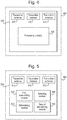
- FIG. 4 shows an example of a transmitter device 400 according to an embodiment of the present invention.
- the transmitter device 400 comprises a plurality of transmitter antennas 410, and processing circuitry 420.
- the processing circuitry 420 may comprise one or more digital processors e.g., one or more microprocessors, microcontrollers, Digital Signal Processors or DSPs, Field Programmable Gate Arrays or FPGAs, Complex Programmable Logic Devices or CPLDs, Application Specific Integrated Circuits or ASICs, or any combination thereof. More generally, the processing circuitry 420 may comprise fixed circuitry, or programmable circuitry that is specially configured via the execution of program instructions implementing the functionality taught herein, or may comprise some combination of fixed and programmable circuitry.
- the processor(s) may be multi-core.
- the processing circuitry 420 may also include a memory.
- the memory stores one or more computer programs and, optionally, configuration data.
- the memory provides non-transitory storage for the computer program and it may comprise one or more types of computer-readable media, such as disk storage, solid-state memory storage, or any combination thereof.
- the memory may comprise any one or more of SRAM, DRAM, EEPROM, and FLASH memory, which may be in the processing circuitry and/or separate from the processing circuitry.
- the memory comprises one or more types of computer-readable storage media providing non-transitory storage of the computer program and any configuration data used by the node.
- the processing circuitry 420 is configured to perform operations, as described in the above embodiments.
- the processing circuitry 420 is configured via the plurality of transmitter antennas 410 to: transmit to a receiving device at a first time, using a first beam-forming precoding vector that maps symbols to be transmitted to the plurality of transmitter antennas; determine, prior to transmitting to the receiving device at a second time, whether an elapsed time since the first time exceeds a first threshold; select one of at least two beam-forming precoding vectors for use in transmitting to the receiving device at the second time, based on said determining; and transmit to the receiving device at the second time, using the selected one of the at least two beam-forming precoding vectors.
- the processing circuitry 420 may further be configured to select the first beam-forming precoding vector for transmitting to the receiving device at the second time, responsive to determining that the elapsed time since the first time does not exceed the first threshold.
- the processing circuitry 420 may further be configured to select a second beam-forming precoding vector for transmitting to the receiving device at the second time, responsive to determining that the elapsed time since the first time exceeds the first threshold.
- the processing circuitry 420 may be configured to, responsive to determining that the elapsed time since the first time exceeds the predetermined threshold, selecting, from among the plurality of transmitter antennas, the transmitter antenna estimated to provide a strongest signal to the receiving device, wherein the second beam-forming precoding vector is an antenna selection precoding vector that maps symbols to be transmitted to the selected transmitter antenna.
- the second beam-forming precoding vector may have an associated decorrelation time that is greater than a decorrelation time associated with the first beam-forming precoding vector.
- the processing circuitry 420 may be configured to calculate the first threshold, for example based on an indication of the decorrelation time of the first beam-forming precoding vector.
- the processing circuitry 420 may be configured to monitor a rotation of the transmitting device, and calculate the first threshold based on said monitoring.
- the processing circuitry 420 may be configured to calculate the first threshold based on accelerometer data and/or gyroscope data of the transmitting device.
- the processing circuitry 420 may be configured to calculate the first threshold, based on estimated Doppler information and/or estimated channel information corresponding to the path between the transmitting device and the receiving device.
- the processing circuitry 420 may further be configured to determine, prior to transmitting to the receiving device at a second time, whether an elapsed time since the first time exceeds a second threshold, the second threshold being a greater time interval than the first threshold, wherein the processing circuitry 420 is configured to select one of the at least two beam-forming precoding vectors for use in transmitting to the receiving device at the second time further based on whether the elapsed time is between the first and second thresholds.
- the processing circuitry 420 may be configured to calculate the first beam-forming precoding vector based on measurements of a pilot signal transmitted by the receiving device.
- the processing circuitry 420 may be configured to calculate the second beam-forming precoding vector based on measurements of the pilot signal transmitted by the receiving device.
- the transmitter device 400 is comprised in a User Equipment 450.
- the transmitter device 400 may be comprised in a radio network node, such as a base station.
- the User Equipment 450 may be configured to operate using discontinuous reception DRX and or discontinuous transmission, DRT.
- the User Equipment may be in discontinuous reception, DRX, mode. That is, the UE may not receive any reference signals from which to calculate beam-forming precoding vectors during this time. This means that the transmitting device may advantageously be more power efficient. Fewer channel estimates and precoder calculations may be required. Further, the overhead in the downlink can be lower, as the receiving device (e.g. network node) does not need to transmit frequency training signals to the transmitting device.
- FIG. 5 shows a further transmitter device 500 embodying the present invention.
- the transmitter device 500 comprises a plurality of transmitter antennas 510.
- the transmitter device 500 comprises a number of functional modules, which may for example be implemented using processing circuitry as defined above.
- the transmitter device 500 comprises a first transmitting module 520 for transmitting to a receiving device at a first time, using a first beam-forming precoding vector that maps symbols to be transmitted to the plurality of transmitter antennas; a determining module 530 for determining, prior to transmitting to the receiving device at a second time, whether an elapsed time since the first time exceeds a first threshold; a selecting module 540 for selecting one of at least two beam-forming precoding vectors for use in transmitting to the receiving device at the second time, based on said determining; and a second transmitting module 550 for transmitting to the receiving device at the second time, using the selected one of the at least two beam-forming precoding vectors.
Landscapes
- Engineering & Computer Science (AREA)
- Computer Networks & Wireless Communication (AREA)
- Signal Processing (AREA)
- Radio Transmission System (AREA)
- Mobile Radio Communication Systems (AREA)
Claims (15)
- Verfahren zum Auswählen von Antennenstrahlformungs-Vorcodierungsvektoren für Übertragungen in einer Übertragungsvorrichtung mit einer Vielzahl von Übertragungsantennen, wobei das Verfahren umfasst:Übertragen (100) an eine Empfangsvorrichtung zu einem ersten Zeitpunkt, unter Verwendung eines ersten Strahlformungs-Vorcodierungsvektors, der der Vielzahl von Übertragungsantennen zu übertragende Symbole zuordnet;Überwachen (232) einer Drehung der Übertragungsvorrichtung;Berechnen (234) eines ersten Schwellenwerts auf Basis des Überwachens;Bestimmen (110), vor dem Übertragen an die Empfangsvorrichtung zu einem zweiten Zeitpunkt, ob eine seit dem ersten Zeitpunkt verstrichene Zeit den ersten Schwellenwert überschreitet;Auswählen (120) von mindestens zwei Strahlformungs-Vorcodierungsvektoren zur Verwendung beim Übertragen an die Empfangseinrichtung zum zweiten Zeitpunkt auf Basis des Bestimmens; undunter Verwendung des ausgewählten einen der mindestens zwei Strahlformungs-Vorcodierungsvektoren, Übertragen (130) an die Empfangseinrichtung zu dem zweiten Zeitpunkt.
- Verfahren nach Anspruch 1, wobei das Verfahren als Reaktion auf das Bestimmen, dass die seit dem ersten Zeitpunkt verstrichene Zeit den ersten Schwellenwert überschreitet, das Auswählen (124) eines zweiten Strahlformungs-Vorcodierungsvektors zum Übertragen an die Empfangseinrichtung zu dem zweiten Zeitpunkt umfasst, und wobei das Verfahren als Reaktion auf das Bestimmen, dass die seit dem ersten Zeitpunkt verstrichene Zeit den vorbestimmten Schwellenwert überschreitet, ferner das Auswählen der Übertragungsantenne aus der Vielzahl von Übertragungsantennen umfasst, von der geschätzt wird, dass sie der Empfangseinrichtung ein stärkstes Signal bereitstellt, und wobei der zweite Strahlformungs-Vorcodierungsvektor ein Antennenauswahl-Vorcodierungsvektor ist, der der ausgewählten Übertragungsantenne zu übertragende Symbole zuordnet.
- Verfahren nach Anspruch 2, wobei der zweite Strahlformungs-Vorcodierungsvektor eine assoziierte Dekorrelationszeit aufweist, die länger als eine mit dem ersten Strahlformungs-Vorcodierungsvektor assoziierte Dekorrelationszeit ist.
- Verfahren nach einem der Ansprüche 1-3, wobei das Verfahren vor der Übertragung an die Empfangsvorrichtung zu einem zweiten Zeitpunkt ferner das Bestimmen umfasst, ob eine verstrichene Zeit seit dem ersten Zeitpunkt einen zweiten Schwellenwert überschreitet, wobei der zweite Schwellenwert ein längeres Zeitintervall ist als der erste Schwellenwert, und wobei das Auswählen (120) von einem der mindestens zwei Strahlformungs-Vorcodierungsvektoren zur Verwendung beim Übertragen an die Empfangsvorrichtung zum zweiten Zeitpunkt ferner darauf basiert, ob die verstrichene Zeit zwischen dem ersten und zweiten Schwellenwert liegt.
- Verfahren nach einem vorstehenden Anspruch, wobei das Verfahren ferner das Berechnen (230) des ersten Schwellenwerts auf Basis einer Schätzung der Dekorrelationszeit des ersten Strahlformungs-Vorcodierungsvektors umfasst.
- Verfahren nach einem vorstehenden Anspruch, wobei das Verfahren das Berechnen (234) des ersten Schwellenwerts auf Basis von Beschleunigungsmesserdaten und/oder Gyroskopdaten von der Übertragungsvorrichtung umfasst.
- Verfahren nach einem der Ansprüche 1-6, wobei das Verfahren ferner das Berechnen (236) des ersten Schwellenwerts auf Basis geschätzter Dopplerinformationen und/oder geschätzter Kanalinformationen entsprechend dem Pfad zwischen der Übertragungsvorrichtung und der Empfangsvorrichtung umfasst.
- Verfahren nach einem der Ansprüche 1-7, wobei das Verfahren ferner das Berechnen (205) des ersten Strahlformungs-Vorcodierungsvektors auf Basis von Messungen eines durch die Empfangseinrichtung übertragenen Pilotsignals umfasst.
- Verfahren von Anspruch 8, wenn abhängig von Anspruch 2, wobei das Verfahren ferner das Berechnen (210) des zweiten Strahlformungs-Vorcodierungsvektors auf Basis von Messungen des durch die Empfangseinrichtung übertragenen Pilotsignals umfasst.
- Computerprogrammprodukt, umfassend Programmanweisungen für einen Prozessor in einer Übertragungsvorrichtung mit einer Vielzahl von Übertragungsantennen, wobei die Programmanweisungen konfiguriert sind, um die Übertragungsvorrichtung zu veranlassen, das Verfahren nach einem vorstehenden Anspruch durchzuführen, wenn die Programmanweisungen durch den Prozessor ausgeführt werden.
- Nicht transitorisches, computerlesbares Medium, umfassend das darauf gespeicherte Computerprogrammprodukt nach Anspruch 10.
- Übertragungsvorrichtung (400), umfassend:eine Vielzahl von Übertragungsantennen (410); undVerarbeitungsschaltlogik (420), die durch die Vielzahl von Übertragungsantennen (410) konfiguriert wird zum:unter Verwendung eines ersten Strahlformungs-Vorcodierungsvektors, der der Vielzahl von Übertragungsantennen zu übertragende Symbole zuordnet, Übertragen zu einem ersten Zeitpunkt an eine Empfangsvorrichtung;wobei die Verarbeitungsschaltlogik konfiguriert ist, um eine Drehung einer Übertragungsvorrichtung zu überwachen (232); undeinen ersten Schwellenwert auf Basis des Überwachens zu berechnen (234);Bestimmen, vor dem Übertragen an die Empfangsvorrichtung zu einem zweiten Zeitpunkt, ob eine verstrichene Zeit seit dem ersten Zeitpunkt den ersten Schwellenwert überschreitet;Auswählen eines der mindestens zwei Strahlformungs-Vorcodierungsvektoren zur Verwendung beim Übertragen an die Empfangseinrichtung zu dem zweiten Zeitpunkt auf Basis des Bestimmens; undunter Verwendung des ausgewählten einen der mindestens zwei Strahlformungs-Vorcodierungsvektoren, Übertragen an die Empfangsvorrichtung zu einem zweiten Zeitpunkt.
- Übertragungsvorrichtung nach Anspruch 12, wobei die Verarbeitungsschaltlogik (420) ferner konfiguriert ist, um den ersten Schwellenwert auf Basis einer Angabe der Dekorrelationszeit des ersten Strahlformungs-Vorcodierungsvektors zu berechnen.
- Benutzereinrichtung (450), umfassend die Übertragungsvorrichtung (420) nach einem der Ansprüche 12 bis 13.
- Benutzereinrichtung (450) nach Anspruch 14, wobei sich die Benutzereinrichtung während der verstrichenen Zeit in einem diskontinuierlichen Empfangsmodus, DRX, befindet.
Applications Claiming Priority (1)
| Application Number | Priority Date | Filing Date | Title |
|---|---|---|---|
| PCT/EP2016/056661 WO2017162303A1 (en) | 2016-03-24 | 2016-03-24 | Method and apparatus for selecting antenna beamforming precoding vectors for transmissions |
Publications (2)
| Publication Number | Publication Date |
|---|---|
| EP3433944A1 EP3433944A1 (de) | 2019-01-30 |
| EP3433944B1 true EP3433944B1 (de) | 2019-10-09 |
Family
ID=55589904
Family Applications (1)
| Application Number | Title | Priority Date | Filing Date |
|---|---|---|---|
| EP16711681.3A Active EP3433944B1 (de) | 2016-03-24 | 2016-03-24 | Verfahren und vorrichtung zur auswahl von antennenstrahlformungsvorcodierungsvektoren für übertragungen |
Country Status (3)
| Country | Link |
|---|---|
| US (1) | US10075225B2 (de) |
| EP (1) | EP3433944B1 (de) |
| WO (1) | WO2017162303A1 (de) |
Families Citing this family (2)
| Publication number | Priority date | Publication date | Assignee | Title |
|---|---|---|---|---|
| EP3769438A1 (de) | 2018-03-19 | 2021-01-27 | IDAC Holdings, Inc. | Verfahren zur nichtorthogonalen uplink-multiplexierung von heterogenen informationstypen |
| CN121643831A (zh) * | 2024-09-04 | 2026-03-10 | 维沃移动通信有限公司 | 预编码信息确定方法、装置及相关设备 |
Family Cites Families (2)
| Publication number | Priority date | Publication date | Assignee | Title |
|---|---|---|---|---|
| ES2424066B1 (es) * | 2012-03-26 | 2014-08-22 | Vodafone España, S.A.U. | Procedimiento y sistema para transmisión mejorada en redes de comunicación móviles |
| US9300373B2 (en) * | 2012-06-19 | 2016-03-29 | Telefonaktiebolaget L M Ericsson (Publ) | Selection of precoding vectors in lean-carrier systems |
-
2016
- 2016-03-24 WO PCT/EP2016/056661 patent/WO2017162303A1/en not_active Ceased
- 2016-03-24 EP EP16711681.3A patent/EP3433944B1/de active Active
- 2016-03-24 US US15/036,107 patent/US10075225B2/en active Active
Non-Patent Citations (1)
| Title |
|---|
| None * |
Also Published As
| Publication number | Publication date |
|---|---|
| US10075225B2 (en) | 2018-09-11 |
| WO2017162303A1 (en) | 2017-09-28 |
| EP3433944A1 (de) | 2019-01-30 |
| US20180091210A1 (en) | 2018-03-29 |
Similar Documents
| Publication | Publication Date | Title |
|---|---|---|
| US11252674B2 (en) | Methods and apparatuses for multi-panel power control | |
| US11005552B2 (en) | Antenna port mode and transmission mode transition | |
| EP2944133B1 (de) | Benutzervorrichtung und verfahren zur leistungssteuerung von aufwärtsstreckenübertragungen | |
| EP3484214B1 (de) | Verfahren, vorrichtung und ausrüstung zur steuerung der leistung einer uplink-übertragung und speichermedium | |
| EP2521279B1 (de) | Leistungsregelungsverfahren und -vorrichtung | |
| EP2747495B1 (de) | Kompensationsverfahren, basisstation und benutzergerät zur uplink-leistungssteuerung in einem comp-system | |
| US8929232B2 (en) | Transmission power control method and mobile station apparatus | |
| CN108112065B (zh) | 发送功率的确定、信令配置方法及装置、终端、基站 | |
| EP2744277A1 (de) | Uplink-leistungssteuerverfahren und -vorrichtung | |
| CN111713153B (zh) | 用于定时提前调整的方法及设备 | |
| EP3855669A1 (de) | Verfahren und vorrichtungen zur klangreferenzsignalkonfiguration und -auslösung in einem drahtlosen kommunikationsnetzwerk | |
| US11265816B2 (en) | Beam based uplink (UL) power control | |
| EP2337409A1 (de) | Verfahren zur steuerung einer übertragungsleistung, basisstationsgerät und mobilstationsgerät | |
| EP3500006A1 (de) | Verfahren zum senden und empfangen von downlink-steuersignalen, vorrichtung, basisstation und endgerät | |
| US20170374624A1 (en) | Uplink transmission power control method and apparatus | |
| CN104412674A (zh) | 用于多用户mimo调度和功率控制的方法和节点 | |
| WO2018059248A1 (zh) | 上行信号发送功率的处理方法及装置、基站、终端 | |
| US20150141070A1 (en) | Mobile station and method of determining transmission power | |
| EP3433944B1 (de) | Verfahren und vorrichtung zur auswahl von antennenstrahlformungsvorcodierungsvektoren für übertragungen | |
| EP2575266A1 (de) | Verfahren, Vorrichtung und Computerprogramm für einen mobilen Sender-Empfänger und einen Basisstations-Sender-Empfänger | |
| EP4264893B1 (de) | Steuerung der übertragung von referenzsignalen | |
| US12587969B2 (en) | Apparatus and method for reducing power consumption in wireless communication |
Legal Events
| Date | Code | Title | Description |
|---|---|---|---|
| STAA | Information on the status of an ep patent application or granted ep patent |
Free format text: STATUS: THE INTERNATIONAL PUBLICATION HAS BEEN MADE |
|
| PUAI | Public reference made under article 153(3) epc to a published international application that has entered the european phase |
Free format text: ORIGINAL CODE: 0009012 |
|
| STAA | Information on the status of an ep patent application or granted ep patent |
Free format text: STATUS: REQUEST FOR EXAMINATION WAS MADE |
|
| 17P | Request for examination filed |
Effective date: 20181003 |
|
| AK | Designated contracting states |
Kind code of ref document: A1 Designated state(s): AL AT BE BG CH CY CZ DE DK EE ES FI FR GB GR HR HU IE IS IT LI LT LU LV MC MK MT NL NO PL PT RO RS SE SI SK SM TR |
|
| AX | Request for extension of the european patent |
Extension state: BA ME |
|
| DAV | Request for validation of the european patent (deleted) | ||
| DAX | Request for extension of the european patent (deleted) | ||
| GRAP | Despatch of communication of intention to grant a patent |
Free format text: ORIGINAL CODE: EPIDOSNIGR1 |
|
| STAA | Information on the status of an ep patent application or granted ep patent |
Free format text: STATUS: GRANT OF PATENT IS INTENDED |
|
| GRAS | Grant fee paid |
Free format text: ORIGINAL CODE: EPIDOSNIGR3 |
|
| GRAA | (expected) grant |
Free format text: ORIGINAL CODE: 0009210 |
|
| STAA | Information on the status of an ep patent application or granted ep patent |
Free format text: STATUS: THE PATENT HAS BEEN GRANTED |
|
| INTG | Intention to grant announced |
Effective date: 20190814 |
|
| AK | Designated contracting states |
Kind code of ref document: B1 Designated state(s): AL AT BE BG CH CY CZ DE DK EE ES FI FR GB GR HR HU IE IS IT LI LT LU LV MC MK MT NL NO PL PT RO RS SE SI SK SM TR |
|
| REG | Reference to a national code |
Ref country code: GB Ref legal event code: FG4D |
|
| REG | Reference to a national code |
Ref country code: CH Ref legal event code: EP |
|
| REG | Reference to a national code |
Ref country code: IE Ref legal event code: FG4D |
|
| REG | Reference to a national code |
Ref country code: DE Ref legal event code: R096 Ref document number: 602016022072 Country of ref document: DE |
|
| REG | Reference to a national code |
Ref country code: AT Ref legal event code: REF Ref document number: 1190030 Country of ref document: AT Kind code of ref document: T Effective date: 20191115 |
|
| REG | Reference to a national code |
Ref country code: NL Ref legal event code: MP Effective date: 20191009 |
|
| REG | Reference to a national code |
Ref country code: LT Ref legal event code: MG4D |
|
| REG | Reference to a national code |
Ref country code: AT Ref legal event code: MK05 Ref document number: 1190030 Country of ref document: AT Kind code of ref document: T Effective date: 20191009 |
|
| PG25 | Lapsed in a contracting state [announced via postgrant information from national office to epo] |
Ref country code: NL Free format text: LAPSE BECAUSE OF FAILURE TO SUBMIT A TRANSLATION OF THE DESCRIPTION OR TO PAY THE FEE WITHIN THE PRESCRIBED TIME-LIMIT Effective date: 20191009 Ref country code: AT Free format text: LAPSE BECAUSE OF FAILURE TO SUBMIT A TRANSLATION OF THE DESCRIPTION OR TO PAY THE FEE WITHIN THE PRESCRIBED TIME-LIMIT Effective date: 20191009 Ref country code: LT Free format text: LAPSE BECAUSE OF FAILURE TO SUBMIT A TRANSLATION OF THE DESCRIPTION OR TO PAY THE FEE WITHIN THE PRESCRIBED TIME-LIMIT Effective date: 20191009 Ref country code: PL Free format text: LAPSE BECAUSE OF FAILURE TO SUBMIT A TRANSLATION OF THE DESCRIPTION OR TO PAY THE FEE WITHIN THE PRESCRIBED TIME-LIMIT Effective date: 20191009 Ref country code: NO Free format text: LAPSE BECAUSE OF FAILURE TO SUBMIT A TRANSLATION OF THE DESCRIPTION OR TO PAY THE FEE WITHIN THE PRESCRIBED TIME-LIMIT Effective date: 20200109 Ref country code: FI Free format text: LAPSE BECAUSE OF FAILURE TO SUBMIT A TRANSLATION OF THE DESCRIPTION OR TO PAY THE FEE WITHIN THE PRESCRIBED TIME-LIMIT Effective date: 20191009 Ref country code: BG Free format text: LAPSE BECAUSE OF FAILURE TO SUBMIT A TRANSLATION OF THE DESCRIPTION OR TO PAY THE FEE WITHIN THE PRESCRIBED TIME-LIMIT Effective date: 20200109 Ref country code: LV Free format text: LAPSE BECAUSE OF FAILURE TO SUBMIT A TRANSLATION OF THE DESCRIPTION OR TO PAY THE FEE WITHIN THE PRESCRIBED TIME-LIMIT Effective date: 20191009 Ref country code: SE Free format text: LAPSE BECAUSE OF FAILURE TO SUBMIT A TRANSLATION OF THE DESCRIPTION OR TO PAY THE FEE WITHIN THE PRESCRIBED TIME-LIMIT Effective date: 20191009 Ref country code: GR Free format text: LAPSE BECAUSE OF FAILURE TO SUBMIT A TRANSLATION OF THE DESCRIPTION OR TO PAY THE FEE WITHIN THE PRESCRIBED TIME-LIMIT Effective date: 20200110 Ref country code: ES Free format text: LAPSE BECAUSE OF FAILURE TO SUBMIT A TRANSLATION OF THE DESCRIPTION OR TO PAY THE FEE WITHIN THE PRESCRIBED TIME-LIMIT Effective date: 20191009 Ref country code: PT Free format text: LAPSE BECAUSE OF FAILURE TO SUBMIT A TRANSLATION OF THE DESCRIPTION OR TO PAY THE FEE WITHIN THE PRESCRIBED TIME-LIMIT Effective date: 20200210 |
|
| PG25 | Lapsed in a contracting state [announced via postgrant information from national office to epo] |
Ref country code: HR Free format text: LAPSE BECAUSE OF FAILURE TO SUBMIT A TRANSLATION OF THE DESCRIPTION OR TO PAY THE FEE WITHIN THE PRESCRIBED TIME-LIMIT Effective date: 20191009 Ref country code: IS Free format text: LAPSE BECAUSE OF FAILURE TO SUBMIT A TRANSLATION OF THE DESCRIPTION OR TO PAY THE FEE WITHIN THE PRESCRIBED TIME-LIMIT Effective date: 20200224 Ref country code: RS Free format text: LAPSE BECAUSE OF FAILURE TO SUBMIT A TRANSLATION OF THE DESCRIPTION OR TO PAY THE FEE WITHIN THE PRESCRIBED TIME-LIMIT Effective date: 20191009 |
|
| PG25 | Lapsed in a contracting state [announced via postgrant information from national office to epo] |
Ref country code: AL Free format text: LAPSE BECAUSE OF FAILURE TO SUBMIT A TRANSLATION OF THE DESCRIPTION OR TO PAY THE FEE WITHIN THE PRESCRIBED TIME-LIMIT Effective date: 20191009 |
|
| REG | Reference to a national code |
Ref country code: DE Ref legal event code: R097 Ref document number: 602016022072 Country of ref document: DE |
|
| PG2D | Information on lapse in contracting state deleted |
Ref country code: IS |
|
| PG25 | Lapsed in a contracting state [announced via postgrant information from national office to epo] |
Ref country code: RO Free format text: LAPSE BECAUSE OF FAILURE TO SUBMIT A TRANSLATION OF THE DESCRIPTION OR TO PAY THE FEE WITHIN THE PRESCRIBED TIME-LIMIT Effective date: 20191009 Ref country code: CZ Free format text: LAPSE BECAUSE OF FAILURE TO SUBMIT A TRANSLATION OF THE DESCRIPTION OR TO PAY THE FEE WITHIN THE PRESCRIBED TIME-LIMIT Effective date: 20191009 Ref country code: EE Free format text: LAPSE BECAUSE OF FAILURE TO SUBMIT A TRANSLATION OF THE DESCRIPTION OR TO PAY THE FEE WITHIN THE PRESCRIBED TIME-LIMIT Effective date: 20191009 Ref country code: DK Free format text: LAPSE BECAUSE OF FAILURE TO SUBMIT A TRANSLATION OF THE DESCRIPTION OR TO PAY THE FEE WITHIN THE PRESCRIBED TIME-LIMIT Effective date: 20191009 Ref country code: IS Free format text: LAPSE BECAUSE OF FAILURE TO SUBMIT A TRANSLATION OF THE DESCRIPTION OR TO PAY THE FEE WITHIN THE PRESCRIBED TIME-LIMIT Effective date: 20200209 |
|
| PLBE | No opposition filed within time limit |
Free format text: ORIGINAL CODE: 0009261 |
|
| STAA | Information on the status of an ep patent application or granted ep patent |
Free format text: STATUS: NO OPPOSITION FILED WITHIN TIME LIMIT |
|
| PG25 | Lapsed in a contracting state [announced via postgrant information from national office to epo] |
Ref country code: IT Free format text: LAPSE BECAUSE OF FAILURE TO SUBMIT A TRANSLATION OF THE DESCRIPTION OR TO PAY THE FEE WITHIN THE PRESCRIBED TIME-LIMIT Effective date: 20191009 Ref country code: SM Free format text: LAPSE BECAUSE OF FAILURE TO SUBMIT A TRANSLATION OF THE DESCRIPTION OR TO PAY THE FEE WITHIN THE PRESCRIBED TIME-LIMIT Effective date: 20191009 Ref country code: SK Free format text: LAPSE BECAUSE OF FAILURE TO SUBMIT A TRANSLATION OF THE DESCRIPTION OR TO PAY THE FEE WITHIN THE PRESCRIBED TIME-LIMIT Effective date: 20191009 |
|
| 26N | No opposition filed |
Effective date: 20200710 |
|
| PG25 | Lapsed in a contracting state [announced via postgrant information from national office to epo] |
Ref country code: MC Free format text: LAPSE BECAUSE OF FAILURE TO SUBMIT A TRANSLATION OF THE DESCRIPTION OR TO PAY THE FEE WITHIN THE PRESCRIBED TIME-LIMIT Effective date: 20191009 |
|
| REG | Reference to a national code |
Ref country code: CH Ref legal event code: PL |
|
| PG25 | Lapsed in a contracting state [announced via postgrant information from national office to epo] |
Ref country code: SI Free format text: LAPSE BECAUSE OF FAILURE TO SUBMIT A TRANSLATION OF THE DESCRIPTION OR TO PAY THE FEE WITHIN THE PRESCRIBED TIME-LIMIT Effective date: 20191009 |
|
| REG | Reference to a national code |
Ref country code: BE Ref legal event code: MM Effective date: 20200331 |
|
| PG25 | Lapsed in a contracting state [announced via postgrant information from national office to epo] |
Ref country code: LU Free format text: LAPSE BECAUSE OF NON-PAYMENT OF DUE FEES Effective date: 20200324 |
|
| PG25 | Lapsed in a contracting state [announced via postgrant information from national office to epo] |
Ref country code: LI Free format text: LAPSE BECAUSE OF NON-PAYMENT OF DUE FEES Effective date: 20200331 Ref country code: FR Free format text: LAPSE BECAUSE OF NON-PAYMENT OF DUE FEES Effective date: 20200331 Ref country code: IE Free format text: LAPSE BECAUSE OF NON-PAYMENT OF DUE FEES Effective date: 20200324 Ref country code: CH Free format text: LAPSE BECAUSE OF NON-PAYMENT OF DUE FEES Effective date: 20200331 |
|
| PG25 | Lapsed in a contracting state [announced via postgrant information from national office to epo] |
Ref country code: BE Free format text: LAPSE BECAUSE OF NON-PAYMENT OF DUE FEES Effective date: 20200331 |
|
| PG25 | Lapsed in a contracting state [announced via postgrant information from national office to epo] |
Ref country code: TR Free format text: LAPSE BECAUSE OF FAILURE TO SUBMIT A TRANSLATION OF THE DESCRIPTION OR TO PAY THE FEE WITHIN THE PRESCRIBED TIME-LIMIT Effective date: 20191009 Ref country code: MT Free format text: LAPSE BECAUSE OF FAILURE TO SUBMIT A TRANSLATION OF THE DESCRIPTION OR TO PAY THE FEE WITHIN THE PRESCRIBED TIME-LIMIT Effective date: 20191009 Ref country code: CY Free format text: LAPSE BECAUSE OF FAILURE TO SUBMIT A TRANSLATION OF THE DESCRIPTION OR TO PAY THE FEE WITHIN THE PRESCRIBED TIME-LIMIT Effective date: 20191009 |
|
| PG25 | Lapsed in a contracting state [announced via postgrant information from national office to epo] |
Ref country code: MK Free format text: LAPSE BECAUSE OF FAILURE TO SUBMIT A TRANSLATION OF THE DESCRIPTION OR TO PAY THE FEE WITHIN THE PRESCRIBED TIME-LIMIT Effective date: 20191009 |
|
| PGFP | Annual fee paid to national office [announced via postgrant information from national office to epo] |
Ref country code: GB Payment date: 20260327 Year of fee payment: 11 |
|
| PGFP | Annual fee paid to national office [announced via postgrant information from national office to epo] |
Ref country code: DE Payment date: 20260327 Year of fee payment: 11 |