EP3432811B1 - Tibiaschnittführung - Google Patents
Tibiaschnittführung Download PDFInfo
- Publication number
- EP3432811B1 EP3432811B1 EP17715610.6A EP17715610A EP3432811B1 EP 3432811 B1 EP3432811 B1 EP 3432811B1 EP 17715610 A EP17715610 A EP 17715610A EP 3432811 B1 EP3432811 B1 EP 3432811B1
- Authority
- EP
- European Patent Office
- Prior art keywords
- cut
- medial
- lateral
- proximal
- assembly
- Prior art date
- Legal status (The legal status is an assumption and is not a legal conclusion. Google has not performed a legal analysis and makes no representation as to the accuracy of the status listed.)
- Active
Links
Images






Classifications
-
- A—HUMAN NECESSITIES
- A61—MEDICAL OR VETERINARY SCIENCE; HYGIENE
- A61B—DIAGNOSIS; SURGERY; IDENTIFICATION
- A61B17/00—Surgical instruments, devices or methods
- A61B17/16—Instruments for performing osteoclasis; Drills or chisels for bones; Trepans
- A61B17/17—Guides or aligning means for drills, mills, pins or wires
- A61B17/1739—Guides or aligning means for drills, mills, pins or wires specially adapted for particular parts of the body
- A61B17/1764—Guides or aligning means for drills, mills, pins or wires specially adapted for particular parts of the body for the knee
-
- A—HUMAN NECESSITIES
- A61—MEDICAL OR VETERINARY SCIENCE; HYGIENE
- A61F—FILTERS IMPLANTABLE INTO BLOOD VESSELS; PROSTHESES; DEVICES PROVIDING PATENCY TO, OR PREVENTING COLLAPSING OF, TUBULAR STRUCTURES OF THE BODY, e.g. STENTS; ORTHOPAEDIC, NURSING OR CONTRACEPTIVE DEVICES; FOMENTATION; TREATMENT OR PROTECTION OF EYES OR EARS; BANDAGES, DRESSINGS OR ABSORBENT PADS; FIRST-AID KITS
- A61F2/00—Filters implantable into blood vessels; Prostheses, i.e. artificial substitutes or replacements for parts of the body; Appliances for connecting them with the body; Devices providing patency to, or preventing collapsing of, tubular structures of the body, e.g. stents
- A61F2/02—Prostheses implantable into the body
- A61F2/30—Joints
- A61F2/38—Joints for elbows or knees
- A61F2/3859—Femoral components
-
- A—HUMAN NECESSITIES
- A61—MEDICAL OR VETERINARY SCIENCE; HYGIENE
- A61B—DIAGNOSIS; SURGERY; IDENTIFICATION
- A61B17/00—Surgical instruments, devices or methods
- A61B17/14—Surgical saws
- A61B17/15—Guides therefor
- A61B17/154—Guides therefor for preparing bone for knee prosthesis
- A61B17/157—Cutting tibia
-
- A—HUMAN NECESSITIES
- A61—MEDICAL OR VETERINARY SCIENCE; HYGIENE
- A61B—DIAGNOSIS; SURGERY; IDENTIFICATION
- A61B17/00—Surgical instruments, devices or methods
- A61B17/16—Instruments for performing osteoclasis; Drills or chisels for bones; Trepans
- A61B17/1662—Instruments for performing osteoclasis; Drills or chisels for bones; Trepans for particular parts of the body
- A61B17/1675—Instruments for performing osteoclasis; Drills or chisels for bones; Trepans for particular parts of the body for the knee
-
- A—HUMAN NECESSITIES
- A61—MEDICAL OR VETERINARY SCIENCE; HYGIENE
- A61F—FILTERS IMPLANTABLE INTO BLOOD VESSELS; PROSTHESES; DEVICES PROVIDING PATENCY TO, OR PREVENTING COLLAPSING OF, TUBULAR STRUCTURES OF THE BODY, e.g. STENTS; ORTHOPAEDIC, NURSING OR CONTRACEPTIVE DEVICES; FOMENTATION; TREATMENT OR PROTECTION OF EYES OR EARS; BANDAGES, DRESSINGS OR ABSORBENT PADS; FIRST-AID KITS
- A61F2/00—Filters implantable into blood vessels; Prostheses, i.e. artificial substitutes or replacements for parts of the body; Appliances for connecting them with the body; Devices providing patency to, or preventing collapsing of, tubular structures of the body, e.g. stents
- A61F2/02—Prostheses implantable into the body
- A61F2/30—Joints
- A61F2/38—Joints for elbows or knees
- A61F2/389—Tibial components
Definitions
- the present subject matter relates to orthopedic procedures and, more particularly, to bone resection apparatuses for performing knee arthroplasties.
- a knee arthroplasty can be used to restore natural knee function by repairing damaged or diseased articular surfaces of the femur and/or tibia.
- An incision is made into the knee joint to expose the bones comprising the joint.
- Cut guides are used to guide the removal of the articular surfaces that are to be replaced.
- Prostheses are used to replicate the articular surfaces.
- Knee prostheses can include a femoral component implanted on the distal end of the femur, which articulates with a tibial component implanted on the proximal end of a tibia to replicate the function of a healthy natural knee.
- FIG. 107 concerns a tibial cutting block with curved tabs which are received between the tibia and condyles of the patient's femur to improve stability.
- the present inventor recognizes, among other things, an opportunity for reducing surgical error and surgical complexity. More particularly, the present inventor has recognized that in a bi-cruciate preserving knee arthroplasty a total femoral component can be used with two independent unicompartmental tibial implants or with two independent bearing components connected together with a bridge shaped tray. Such arrangement, however, can require the surgeon to determine a proper spacing for the tibial components such that they articulate properly with the femoral component and are arranged in a desired manner on the resected tibia. Mismatch or error in spacing the tibia components can result in high rates of wear and/or loading that may result in component loosening or other complications.
- the present inventor proposes exemplary cut guides that can attach to the femoral component to better reference a medial-lateral geometry of the femoral component.
- the cut guides can include at least one sagittal capture for sagittal resection(s) of the tibia so that the tibial implant(s) can be positioned with a desired bearing(s) spacing and with a desired medial-lateral position that can optimize articulation between the femoral component and the tibial components so as to reduce the likelihood of wear and other complications.
- the present inventor has recognized that surgical complexity can be reduced by providing cut guides with a sagittal capture and/or transverse capture that predefines a cut medial-lateral relative to one or more articulating surfaces of the femoral component.
- the cut guide can be configured to provide the surgeon with various movement options including translation proximal-distal to achieve a desired sagittal cut depth, translation medial-lateral as patient geometry dictates and rotation such as to accommodate various degrees of flexion so the surgeon can set the cut guide in an appropriate location relative to the tibia so that resections can be performed in desired locations.
- Further examples of the cut guide may not connect to the femoral component to mount the cut guide thereto but instead can have one or more members that reference articular surface(s) of the femoral component and/or the femur.
- the present invention provides an apparatus for guiding resection of a tibia during a knee replacement surgery as defined in claim 1.
- the scope of the invention is defined by the appended claims.
- the present application relates to devices that can be used in a bi-cruciate preserving knee arthroplasty sometimes referred to as a bicompartmental knee replacement procedure.
- the techniques described are also applicable to a unicompartmental knee replacement procedure and/or a total knee replacement procedure (TKA).
- TKA total knee replacement procedure
- the bicompartmental knee replacement procedure can comprise a procedure that utilize two unicompartmental knee replacements and two femoral components, a procedure that utilizes a single (total) femoral component and two unicompartmental tibial components, a procedure that utilizes the single (total) femoral component and two unicompartmental bearings attached together by a U-shaped tibial tray and other types of knee replacement procedures.
- the disclosed devices include tibial cut guides having a mounting portion configured to couple with an alignment mechanism and a second portion connected to the mounting portion.
- the second portion can define a capture for a proximal cut and can have an aperture disposed adjacent a first end of the capture.
- the second portion can include a second capture for a sagittal cut.
- FIG. 1A illustrates a natural femur 10 and tibia 12.
- the femur 10 can include medial 14 and lateral 16 condyles at a distal end of the femur 10.
- Various ligaments can be attached to the femur 10 and/or the tibia 12.
- An anterior cruciate ligament (ACL) 18 can extend from an anterior side of the tibia 12 to the femur 10
- a posterior cruciate ligament (PCL) 20 can extend from a posterior side of the tibia 12 to the femur 10.
- FIG. 1A illustrates a natural femur 10 and tibia 12.
- the femur 10 can include medial 14 and lateral 16 condyles at a distal end of the femur 10.
- Various ligaments can be attached to the femur 10 and/or the tibia 12.
- An anterior cruciate ligament (ACL) 18 can extend from an anterior side of the tibia 12
- 1B is a top view of the tibia 12 and further illustrates some of these ligaments as well as a medial meniscus 22 and a lateral meniscus 24 that are located between the tibia 12 and the medial 14 and lateral 16 condyles.
- FIG. 1C illustrates a posterior side view of the tibia 12 with the ligaments and other anatomical features shown in FIG. 1B removed.
- the tibia 12 can include an intercondylar eminence 26, which is a bony elevation or raised area between a medial articular surface 28 and a lateral articular surface 30 at a proximal end of the tibia 12.
- the intercondylar eminence 26 can include medial 32 and lateral 34 tubercles extending from the intercondylar eminence 26.
- the ACL 18 and PCL 20 are attached to the tibia 12 at locations anterior and posterior, respectively, to the intercondylar eminence 26.
- the PCL 20 is attached to the tibia 12 at a location 36 on a posterior end of the tibia 12.
- the medial 14 and lateral 16 condyles of the femur 10 are resected.
- the tibia 12 is resected to remove both of the medial articular surface 28 and the lateral articular surface 30 using a cutting apparatus such as those disclosed herein. More particularly, femoral cutting apparatuses can be utilized to remove portions of the femur 10 that would otherwise interface with either the medial articular surface 28 or the lateral articular surface 30. Prostheses would be implanted on the femur 10 and the tibia 12 providing for the replaced articular surfaces.
- portions of the knee e.g., the intercondylar eminence 26, ACL 18, and PCL 20 can be maintained in the bicompartmental knee replacement procedure.
- a unicompartmental knee replacement procedure one the medial 14 and lateral 16 condyles of the femur 10 are resected and one of the medial articular surface 28 and the lateral articular surface 30 of the tibia 12 is resected.
- Such resection of the tibia 12 can be performed using a cutting apparatus as disclosed herein.
- the unicompartmental knee replacement procedure maintains portions of the knee such as the intercondylar eminence 26, ACL 18, etc.
- a bicompartmental knee replacement procedure that would utilize a total femoral component and two unicompartmental tibial components or two tibial bearings and a U-shaped tibial tray can seek to maintain portions of the knee such as the intercondylar eminence 26.
- proximal refers to a direction generally toward the torso of a patient
- distal refers to the opposite direction of proximal, i.e., away from the torso of a patient
- anterior refers to front of the patient
- posterior refers to the opposite direction of anterior back side of the patient or knee. In the context of cutting apparatus such as those disclosed herein, such directions correspond to the orientation of the apparatus when in use (i.e.
- a proximal portion of the cutting apparatus is that portion which will ordinarily be closest to the torso of the patient, the anterior portion closest to the surgeon, the posterior portion generally closest to the anterior portion of the patient's knee, etc.
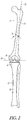
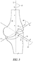
- FIGS. 2-3 illustrate several aspects of implant orientation.
- FIG. 2 illustrates various axes of the lower limb in the frontal plane. Axes can be defined for each segment of the lower limb.
- the femur 10 has an anatomic axis 32 coinciding generally with its intramedullary canal. It also has a mechanical axis 34, or load axis, running from the center of the femoral head to the center of the knee.
- the angle 36 between these two axes 32, 34 in the frontal plane varies within the patient population but is on the order of 4-9°.
- the two axes 32, 34 are approximately superimposed in the sagittal plane.
- the tibia 12 has a mechanical axis 38 coinciding generally with its intramedullary canal.
- the mechanical axis 38 of the tibia 12 runs from the center of the knee to the center of the ankle.
- the transverse axis, or joint line 39, about which the knee flexes, is parallel to a line through the medial and lateral femoral condyles and parallel to the tibial plateau.
- the distal femur and proximal tibia are resected to be parallel to the joint line 39, and thus perpendicular to the mechanical axes 34, 38 as indicated at 40 and 42.
- intersection of the femoral and tibial mechanical axes 34, 38 may subtend a small angle relative to one another.
- the angle can be small such that the axes 34, 38 are approximately collinear and may be treated as collinear for most purposes.
- FIG. 3 depicts six aspects of component positioning relative to a coordinate system in which the x-axis 70 corresponds approximately to the joint line 39, the z-axis 72 corresponds approximately to the mechanical axes 34 and 38, and the y-axis 74 is normal to the other two. Position along each of these axes is depicted by arrows. Position along the x, y, and z axes determines the medial-lateral (dx) 76, anterior-posterior (dy) 78, and proximal-distal (dz) 80 positioning of components respectively. Rotation about each of these axes is also depicted by arrows.
- Rotation about the z-axis (rz) 82 corresponds anatomically to internal-external rotation of the femoral component
- rotation about the x-axis (rx) 84 corresponds to flexion-extension rotation
- rotation about the y-axis (ry) 86 corresponds to varus/valgus rotation.
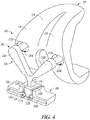
- FIG. 4 shows an assembly 100 of a tibial cut guide 102 and a femoral component 103 according to an example embodiment.
- the tibial cut guide 102 can be connected to the femoral component 103 so as to be mounted thereto.
- the tibial guide 102 can include a mounting portion 104 and a cutting portion 106.
- the cutting portion 106 can include a body 108, slots 110A, 110B, 110C, and 110D, and apertures 112A and 112B.
- the body can include an intercondylar portion 114.
- the femoral component 103 can include a medial condyle 116, a lateral condyle 118, and connection features 120A and 120B.
- the tibial cut guide 102 of FIG. 5 can be configured for resecting one or both the medial and lateral compartments of the tibia. As such, the tibial cut guide 102 can be utilized to perform either the bicompartmental knee replacement procedure or the unicompartmental knee replacement procedure as described previously herein. With small modification (one single slot extending from substantially a lateral side to a medial side) the tibial cut guide can be used for a total knee replacement as well.
- the mounting portion 104 can connect to the femoral component 103 at proximal ends thereof and can extend distally to connect with the cutting portion 106.
- a posterior surface of the cutting portion 106 can be configured to interface with an anterior portion of the tibia.
- the body 108 can comprise a frame that defines the slots 110A, 110B, 110C, and 110D.
- the slot 110A can be oriented generally medial-lateral for a first proximal cut.
- the slot 110B can be spaced from the slot 110A and can be oriented generally medial-lateral for a second proximal cut.
- the intercondylar portion 114 can space the slot 110A from the second slot 110B.
- the slot 110C can be configured for a first sagittal cut.
- the slot 110D can be spaced from the slot 110C by the intercondylar portion 114 and can be configured for a second sagittal cut.
- the tibial cut guide 102 can be configured such that first sagittal cut can be on a first side (e.g., a more lateral side) of the intercondylar portion 114 and the second sagittal cut on a second side (e.g., a more medial side) of the intercondylar portion 114.
- the body 108 can additionally define apertures 112A and 112B disposed to either side of the intercondylar portion 114, respectively.
- the aperture 112A can be disposed between the slot 110C for the first sagittal cut and the slot 110A for the first proximal cut.
- the aperture 112B can be disposed between the slot 110D for the second sagittal cut and the slot 110B for the second proximal cut.
- the aperture 112A can communicate with the slots 110A and 110C and the aperture 112B can communicate with the slots 110B and 110D.
- the apertures 112A and 112B can be spaced from the slots 110A, 110B, 110C, and 110D by portions of the body 108.
- the aperture 112A can be disposed between the first of the one or more slots for the first sagittal cut and the second of the one or more slots for the first proximal cut.
- the apertures 112A and 112B can be configured to receive one of a pin or screw (e.g., a stop or fixation component that separates the slots) therein.
- the screw or pin can provide for fixation of the cut guide 102 relative to the tibia.
- the screw or pin inserted in the aperture(s) 112A and 112B can provide a stop for the saw blade to protect the bone from over-resection.
- fixation of the body 108 can be achieved by securing with pins/screws through the connection features.
- the slot 110A can be configured to define a first medial-lateral cut length and the slot 110B can be configured to define a second medial-lateral length. This can allow for the first and the second proximal cut to the tibia each of the first proximal cut and the second proximal cut to a different single (medial and/or lateral) compartment of the knee. In some cases the first medial-lateral cut length can differ from the second medial-lateral cut length.
- the femoral component 103 can comprise a total femoral component that is a provisional (temporary) component with the medial condyle 116 spaced from the lateral condyle 118 by a patellar flange 119.
- the connection features 120A and 120B can be disposed in the medial condyle 116 and the lateral condyle 118, respectively.
- the first arm 124A and the second arm 124B can be made adjustable about the intermediate portion 126 such that the mounting portion 104 can be attached to various sizes of femoral provisionals.
- FIG. 4 illustrates the mounting portion 104, which can be configured to connect to the femoral component 103 with connection features 122A and 122B that are configured to couple with the connection features 120A and 120B, respectively.
- the connection of the mounting portion 104 to the femoral component 103 can mount the cutting portion 102 relative to the tibia.
- the connection features 122A and 122B can comprise male features configured to couple with female features (connection features 120A and 120B).
- the connection features 122A and 122B can utilize tabs, treading, or other types of mechanical means known in the art to facilitate coupling with the connection features 120A and 120B.
- the mounting portion 104 can include a first arm 124A having the first male connection feature 122A at an end thereof configured to connect with a first female connection feature 120A in the medial condyle 116.
- the mounting portion 104 additionally can include a second arm 124B having the second male connection feature 122B at an end thereof configured to connect with the second female connection feature 120B in the lateral condyle 118.
- the mounting portion 104 can have an intermediate portion 126 that can be connected to the first arm 124A and the second arm 124B at a proximal end portion thereof.
- the intermediate portion 126 can be connected to the cutting portion 106 at a distal end portion thereof.
- FIG. 5 shows the assembly 100 of the tibial cut guide 102 and the femoral component 103 disposed in a knee joint 150 according to one example.
- the tibial cut guide 102 can be connected to mount to the femoral component 103 to interface with the anterior portion of a tibia 152.
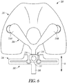
- FIG. 6 shows an assembly 200 according to another example that can include a tibial cut guide 202 and a femoral component 203.
- the tibial cut guide 202 can couple to the femoral component 203 in the manner discussed previously with regard to the example of FIGS. 4 and 5 .
- the tibial cut guide 202 can include a mounting portion 204 and a cutting portion 206.
- the mounting portion 204 can additionally include an adjustment member 208.
- the cutting portion 206 can include an adjustment mechanism 210.
- the adjustment mechanism 210 can be disposed at an intercondylar portion 212 of the cutting portion 206.
- the adjustment member 208 can extend generally in the proximal-distal direction from a junction with the arms 214A and 214B of the mounting portion 204.
- the adjustment mechanism 210 can be configured to selectively couple with the adjustment member 208. More particularly, the adjustment mechanism 210 can receive the adjustment member 208, which can extend therethrough.
- the adjustment mechanism 210 can comprise a knob clamp 216 according to the example of FIG. 6 .
- the adjustment member 208 can comprise another mechanical device that allows for selective locking, unlocking and adjustment (e.g., a ratchet, a gear, a clutch, a pin(s), or the like).
- the knob clamp 216 can be selectively loosened to allow for generally proximal-distal adjustment of the cutting portion 206 relative to the mounting portion 204 along the adjustment member 208.
- adjustment member 208 can be provided with teeth, recesses, or other mechanisms to facilitate selective locking with the adjustment mechanism 210.
- the adjustment member 210 and adjustment member 208 can be configured to allow for between 0 mm and 15 mm of generally proximal-distal movement of the cutting portion 206 relative to the mounting portion 204 as indicated by arrow A.
- FIG. 7 shows an assembly 300 according to another example that can include a tibial cut guide 302 and a femoral component 303.
- the tibial cut guide 302 can couple to the femoral component 303 in the manner discussed previously with regard to the example of FIGS. 4 and 5 .
- the tibial cut guide 302 can include a mounting portion 304 and a cutting portion 306.
- the mounting portion 304 can additionally include an adjustment member 308 and the cutting portion 306 can include an adjustment mechanism 310 to facilitate generally proximal-distal adjustment (indicated by arrow Ai) of the cutting portion 306 relative to the mounting portion 304 as previously discussed in reference to the example of FIG. 6 .
- the mounting portion 304 can further include a second adjustment mechanism 312, a second adjustment member 314 and stops 316A and 316B.
- the second adjustment mechanism 312 can connect with the adjustment member 308 and can be selectively coupled with the adjustment mechanism 310.
- the second adjustment member 314 can extend generally transverse relative to the adjustment member 308 and can extend between a medial condyle 318 and a lateral condyle 320 of the femoral component 303.
- the stops 316A and 316B can be disposed on medial and lateral ends of the second adjustment member 314.
- the second adjustment mechanism 312 can be configured to receive the second adjustment member 314 and can allow for passage of the second adjustment member 314 therethrough.
- the second adjustment mechanism 312 can be configured to selectively lock and unlock relative to the second adjustment member 314. This can allow for medial-lateral translation (indicated by arrow A 2 ) of the second adjustment mechanism 312 (and hence medial-lateral translation of the cutting portion 306 via the adjustment member 308) relative to the second adjustment member 314 and the medial and lateral condyles 318, 320 between the stops 316A and 316B. According to further examples, the stops 316A and 316B can be removed to allow for more unrestricted translation of the second adjustment mechanism 312 relative to the second adjustment member 314.
- the second adjustment mechanism 312 can additionally be configured to facilitate rotation (indicated by arrows R 1 and R 2 ) and selective locking and unlocking of the adjustment member 308 (and hence rotation of the cutting portion 306).
- Such rotation can be about the z-axis (rz) 82 ( FIG. 3 ) which corresponds anatomically to internal-external rotation of the femoral component and/or about the x-axis (rx) 84 ( FIG. 3 ) which corresponds to flexion-extension rotation.
- the second adjustment mechanism 312 can utilize various mechanical features (knobs, screws, articulating joints, ratchets, or the like) to facilitate translation and/or rotation, locking and unlocking of the cutting portion 306 relative to the femoral component 303 and tibia (not shown).
- the adjustment mechanisms 310, 312 can adjust a position of the cutting portion 306 in one or more of rotation, a proximal-distal direction and a medial-lateral position.
- the second adjustment mechanism 312 can comprise a medial-lateral translation mechanism, a flexion-extension rotation mechanism and an internal-external rotation mechanism.
- the adjustment mechanism 310 can comprise a proximal-distal translation mechanism.
- the adjustment mechanisms 310, 312 can facilitate timely adjustment of the tibial cut guide 302 relative to femoral component 303 to accommodate physician preference, differences in patient anatomy and varying degree of flexion of the knee joint. Adjustment of the position of the tibial cut guide 302 relative to the femoral component 303 and the tibia 12 ( FIGS. 1B and 1C ) can be made with reference to at least one or more anatomical landmarks of the tibia 12 and/or the femur 10.
- the anatomical landmarks include one or more of the intercondylar eminence 26, a connection position of the ACL 18, a medial third of the tubercle at insertion of the PCL 20, and an intercondylar geometry of the femur 10.
- FIG. 8 shows an assembly 400 according to another example that can include a tibial cut guide 402 and a femoral component 403.
- the tibial cut guide 402 can be constructed in the manner discussed previously with regard to the example of FIGS. 4 , 5 , 6 and 7 and therefore, will not be discussed in great detail.
- the cut guide can include a mounting portion 404 and a cutting portion 406.
- the femoral component 403 includes a medial condyle 408, a lateral condyle 410, a first slot 412A and a second slot 412B.
- the femoral component 403 can comprise a total femoral component that is a provisional component.
- the first slot 412A can be disposed in the medial condyle 408 and can be configured to receive a medial end of the mounting portion 404 therein.
- the second slot 412B can be disposed in the lateral condyle 410 and can be configured to receive a lateral end of the mounting portion 404 therein.
- the first and second slots 412A, 412B can be configured to facilitate orientation of the cutting portion 406 in a desired position relative to the femoral component 403 and the tibia (not shown).
- the first and second slots 412A, 412B can be used to accommodate physician preference, differences in patient anatomy (e.g., for resection depth) and varying degree of flexion of the knee joint.
- FIGS. 9A and 9B show a tibial cut guide 502 according to another example.
- the tibial cut guide 502 can be constructed to have slots including sagittal slots 504A and 504B arranged in the manner previously described in reference to the example FIGS. 4 and 5 .
- the tibial cut guide 502 can additionally include a mounting portion 506 comprised of a first arm 506A and a second arm 506B.
- the first arm 506A and the second arm 506B can be configured to extend proximally and posteriorly from a cutting portion 508 of the tibial cut guide.
- the first and second arms 506A and 506B can be configured to position the apparatus relative to a medial condyle 510 and a lateral condyle 512 of the femur 514. According to some examples, the first arm 506A and the second arm 506B can rest upon the medial and lateral compartments 516, 518 of the tibia 520.
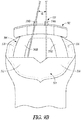
- FIGS. 9B illustrates an example where a first sagittal cut defined by the slot 504A is canted at an acute angle ⁇ (as viewed from an elevated proximal position) relative to a second sagittal cut defined by the slot 504B.
- FIG. 10 shows a bicompartmental knee replacement procedure that can be performed using one or more of the tibia cut guides described herein.
- the medial and lateral condyles of the femur 610 are resected.
- the tibia 612 is resected to remove both of the medial articular surface and the lateral articular surface using the tibial cut guides such as those disclosed herein.
- Prostheses e.g., a total femoral prosthesis 614 and two unicompartmental tibial implants 616A and 606B
- Other portions of the knee e.g., the intercondylar eminence 626, ACL 618, and PCL can be maintained in the bicompartmental knee replacement procedure due to the configuration of the tibial cut guides.
- FIG. 11 shows a bicompartmental knee replacement procedure that can utilize a total femoral component (such as the total femoral prosthesis 614 of FIG. 10 ), two tibial bearings 710A and 710B, and a U-shaped tibial tray 712 and seeks to maintain portions of the tibia 714 such as the intercondylar eminence 726 and the ACL 718.
- the bicompartmental arrangement of FIG. 11 can be performed using one or more of the tibia cut guides described herein.
Landscapes
- Health & Medical Sciences (AREA)
- Life Sciences & Earth Sciences (AREA)
- Orthopedic Medicine & Surgery (AREA)
- Surgery (AREA)
- Biomedical Technology (AREA)
- Veterinary Medicine (AREA)
- Oral & Maxillofacial Surgery (AREA)
- Public Health (AREA)
- General Health & Medical Sciences (AREA)
- Engineering & Computer Science (AREA)
- Animal Behavior & Ethology (AREA)
- Heart & Thoracic Surgery (AREA)
- Physical Education & Sports Medicine (AREA)
- Transplantation (AREA)
- Medical Informatics (AREA)
- Molecular Biology (AREA)
- Dentistry (AREA)
- Nuclear Medicine, Radiotherapy & Molecular Imaging (AREA)
- Cardiology (AREA)
- Vascular Medicine (AREA)
- Prostheses (AREA)
- Surgical Instruments (AREA)
Claims (15)
- Anordnung (100), umfassend eine Femurkomponente (103) und eine Vorrichtung (102) zum Führen einer Resektion einer Tibia während einer Knieersatzoperation, wobei die Femurkomponente (103) einen medialen (116) und einen lateralen (118) Kondylus umfasst;
wobei die Vorrichtung Folgendes umfasst:einen ersten Abschnitt (104), der dazu konfiguriert ist, die Vorrichtung relativ zu dem medialen Kondylus der Femurkomponente und dem lateralen Kondylus der Femurkomponente zu positionieren, undeinen zweiten Abschnitt (106), der mit dem ersten Abschnitt verbunden ist und einen oder mehrere Schlitze (110A, 110B, 110C, 110D) definiert, wobei die Schlitze für mindestens einen von einem ersten proximalen Schnitt und einem ersten sagittalen Schnitt zu der Tibia konfiguriert sind, wobei der erste Abschnitt (104) Folgendes umfasst:einen ersten Arm (124A) mit einem ersten Steckermerkmal (122A), das dazu konfiguriert ist, sich mit einem ersten Buchsenmerkmal (120A) in dem medialen Kondylus (116) der Femurkomponente (103) zu verbinden;einen zweiten Arm (124B) mit einem zweiten Steckermerkmal (122B), das dazu konfiguriert ist, sich mit einem zweiten Buchsenmerkmal (120B) in dem lateralen Kondylus (118) der Femurkomponente (103) zu verbinden; undeinen Zwischenabschnitt (126), der mit dem ersten Arm (124A) und dem zweiten Arm (124B) an einem proximalen Endabschnitt verbunden ist und mit dem zweiten Abschnitt (106) an einem distalen Endabschnitt verbunden ist. - Anordnung nach Anspruch 1, wobei die Vorrichtung ferner mindestens eine Öffnung (112A, 112B) umfasst, die zwischen dem ersten des einen oder der mehreren Schlitze (110C) für den ersten sagittalen Schnitt und dem zweiten des einen oder der mehreren Schlitze (110A) für den ersten proximalen Schnitt angeordnet ist, wobei die Öffnung (112A, 112B) dazu konfiguriert ist, eine von einer Stoppkomponente oder einer Fixierkomponente darin aufzunehmen.
- Anordnung nach einem oder einer beliebigen Kombination der Ansprüche 1 und 2, wobei der eine oder die mehreren Schlitze dazu konfiguriert sind, eine erste medial-laterale Schnittlänge zu definieren, so dass der erste proximale Schnitt zu einem ersten einzelnen Kompartiment der Tibia führt.
- Anordnung nach Anspruch 3, wobei der eine oder die mehreren Schlitze dazu konfiguriert sind, eine zweite medial-laterale Schnittlänge zu definieren, die von der ersten medial-lateralen Schnittlänge durch einen interkondylären Abschnitt (114) beabstandet ist, so dass ein zweiter proximaler Schnitt zu einem zweiten einzelnen Kompartiment der Tibia führt.
- Anordnung nach Anspruch 4, wobei der eine oder die mehreren Schlitze (110C, 110D) dazu konfiguriert sind, den ersten sagittalen Schnitt auf einer ersten Seite des interkondylären Abschnitts und einen zweiten sagittalen Schnitt auf einer zweiten Seite des interkondylären Abschnitts zu definieren.
- Anordnung nach Anspruch 5, wobei der erste sagittale Schnitt in Bezug auf den zweiten sagittalen Schnitt in einem spitzen Winkel geneigt ist.
- Anordnung nach einem oder einer beliebigen Kombination der Ansprüche 1 bis 6, wobei der erste Abschnitt dazu konfiguriert ist, mit einem oder beiden von dem medialen Kondylus der Femurkomponente und dem lateralen Kondylus der Femurkomponente verbunden zu werden.
- Anordnung nach einem oder einer beliebigen Kombination der Ansprüche 1 bis 6, wobei die Vorrichtung einen oder mehrere Einstellmechanismen beinhaltet, um eine Position des zweiten Abschnitts in einer oder mehreren von Rotation, proximal-distaler Richtung und medial-lateraler Position einzustellen.
- Anordnung nach Anspruch 8, wobei der eine oder die mehreren Einstellmechanismen mindestens einen von einem proximal-distalen Translationsmechanismus, einem medial-lateralen Translationsmechanismus, einem Extensionsebenen-Rotationsmechanismus und einem externen Rotationsmechanismus umfassen.
- Anordnung nach einem oder einer beliebigen Kombination der Ansprüche 1-8, wobei die Femurkomponente eine Gesamtfemurkomponente umfasst und das erste Buchsenmerkmal ein erster Schlitz (120A) ist und das zweite Buchsenmerkmal ein zweiter Schlitz (120B) ist, die dazu konfiguriert sind, eine Ausrichtung des ersten Abschnitts (104) in einer gewünschten Position in Bezug auf die Femurkomponente (103) zu erleichtern.
- Anordnung nach Anspruch 1 zum Führen einer Resektion einer Tibia während einer bikompartimentellen Knieersatzoperation, wobei der zweite Abschnitt (106) eine Vielzahl von Schlitzen (110A, 110B, 110C, 110D) definiert, die für mindestens einen ersten proximalen Schnitt, einen ersten sagittalen Schnitt, einen zweiten proximalen Schnitt und einen zweiten sagittalen Schnitt zu der Tibia konfiguriert sind, wobei die Schlitze dazu konfiguriert sind, eine erste medial-laterale Schnittlänge zu definieren, so dass der erste proximale Schnitt zu einem ersten einzelnen Kompartiment der Tibia führt, und dazu konfiguriert ist, eine zweite medial-laterale Schnittlänge zu definieren, so dass der zweite proximale Schnitt zu einem zweiten einzelnen Kompartiment der Tibia führt.
- Anordnung nach Anspruch 11, ferner umfassend mindestens eine Öffnung, die zwischen einem der Vielzahl von Schlitzen für den ersten sagittalen Schnitt und einem anderen der Vielzahl von Schlitzen für den ersten proximalen Schnitt angeordnet ist, wobei die Öffnung dazu konfiguriert ist, eine von einer Stoppkomponente oder einer Befestigungskomponente darin aufzunehmen.
- Anordnung nach einem oder einer beliebigen Kombination der Ansprüche 11 und 12, wobei die zweite medial-laterale Schnittlänge von der ersten medial-lateralen Schnittlänge durch einen interkondylären Abschnitt beabstandet ist und die Schlitze dazu konfiguriert sind, den ersten sagittalen Schnitt auf einer ersten Seite des interkondylären Abschnitts und einen zweiten sagittalen Schnitt auf einer zweiten Seite des interkondylären Abschnitts zu definieren.
- Anordnung nach Anspruch 13, wobei der erste sagittale Schnitt in Bezug auf den zweiten sagittalen Schnitt in einem spitzen Winkel geneigt ist.
- Anordnung nach einem oder einer beliebigen Kombination der Ansprüche 11-14, wobei die Vorrichtung einen oder mehrere Einstellmechanismen beinhaltet, um eine Position des zweiten Abschnitts in einer oder mehreren von Rotation, proximal-distaler Richtung und medial-lateraler Position einzustellen.
Applications Claiming Priority (2)
| Application Number | Priority Date | Filing Date | Title |
|---|---|---|---|
| US201662312808P | 2016-03-24 | 2016-03-24 | |
| PCT/US2017/023826 WO2017165653A1 (en) | 2016-03-24 | 2017-03-23 | Tibial cut guide |
Publications (2)
| Publication Number | Publication Date |
|---|---|
| EP3432811A1 EP3432811A1 (de) | 2019-01-30 |
| EP3432811B1 true EP3432811B1 (de) | 2022-01-05 |
Family
ID=58489105
Family Applications (1)
| Application Number | Title | Priority Date | Filing Date |
|---|---|---|---|
| EP17715610.6A Active EP3432811B1 (de) | 2016-03-24 | 2017-03-23 | Tibiaschnittführung |
Country Status (3)
| Country | Link |
|---|---|
| US (2) | US10517616B2 (de) |
| EP (1) | EP3432811B1 (de) |
| WO (1) | WO2017165653A1 (de) |
Families Citing this family (4)
| Publication number | Priority date | Publication date | Assignee | Title |
|---|---|---|---|---|
| EP3432811B1 (de) | 2016-03-24 | 2022-01-05 | Zimmer, Inc. | Tibiaschnittführung |
| WO2022040952A1 (zh) * | 2020-08-26 | 2022-03-03 | 王志坚 | 人工膝关节置换术的运动轴定位器 |
| US12193775B2 (en) | 2022-05-06 | 2025-01-14 | Jpi Consulting | Method and system for remote robotic control of positioning of an instrument |
| US12303213B2 (en) | 2022-07-21 | 2025-05-20 | Jpi Consulting | Preoperative imaging combined with intraoperative navigation before and after removal of an implant from a surgical site to create a composite surgical three dimensional structural dataset |
Family Cites Families (10)
| Publication number | Priority date | Publication date | Assignee | Title |
|---|---|---|---|---|
| US5597379A (en) * | 1994-09-02 | 1997-01-28 | Hudson Surgical Design, Inc. | Method and apparatus for femoral resection alignment |
| US8083745B2 (en) | 2001-05-25 | 2011-12-27 | Conformis, Inc. | Surgical tools for arthroplasty |
| US8317797B2 (en) * | 2005-02-08 | 2012-11-27 | Rasmussen G Lynn | Arthroplasty systems and methods for optimally aligning and tensioning a knee prosthesis |
| AU2008274854B2 (en) * | 2007-07-09 | 2013-09-26 | Orthosoft Ulc | Universal positioning device for orthopedic surgery and method of use thereof |
| EP2957243A1 (de) * | 2007-09-30 | 2015-12-23 | DePuy Products, Inc. | Massgeschneidertes patientespezifisches orthopädisches chirurgisches instrument |
| WO2012024306A2 (en) | 2010-08-16 | 2012-02-23 | Aashiish Agnihotri | Surgical guides |
| CN103237510B (zh) * | 2010-10-14 | 2017-04-05 | 史密夫和内修有限公司 | 患者匹配的器械和方法 |
| EP2884908B1 (de) * | 2012-08-09 | 2021-11-24 | Smith & Nephew, Inc. | Intraoperatv einstellbare schneideführung |
| US10206696B2 (en) * | 2015-01-09 | 2019-02-19 | Danton S. Dungy | Devices and methods for establishing femoral and tibial resection positions in a total knee replacement procedure |
| EP3432811B1 (de) | 2016-03-24 | 2022-01-05 | Zimmer, Inc. | Tibiaschnittführung |
-
2017
- 2017-03-23 EP EP17715610.6A patent/EP3432811B1/de active Active
- 2017-03-23 US US15/467,663 patent/US10517616B2/en active Active
- 2017-03-23 WO PCT/US2017/023826 patent/WO2017165653A1/en not_active Ceased
-
2019
- 2019-11-27 US US16/698,509 patent/US11571224B2/en active Active
Non-Patent Citations (1)
| Title |
|---|
| None * |
Also Published As
| Publication number | Publication date |
|---|---|
| WO2017165653A1 (en) | 2017-09-28 |
| US20200093502A1 (en) | 2020-03-26 |
| EP3432811A1 (de) | 2019-01-30 |
| US11571224B2 (en) | 2023-02-07 |
| US10517616B2 (en) | 2019-12-31 |
| US20170273696A1 (en) | 2017-09-28 |
Similar Documents
| Publication | Publication Date | Title |
|---|---|---|
| AU2016289953B2 (en) | Femoral finishing guide | |
| US12290272B2 (en) | Tibial cut guide | |
| EP1778559B1 (de) | Modulare vorrichtung zum formen der fläche eines gelenks | |
| US10485553B2 (en) | Knee resection and gap balancing instruments and techniques | |
| EP3485849B1 (de) | Implantate zum hinzufügen von gelenkneigung zu einer kniearthroplastie | |
| US11141291B2 (en) | Femoral trial components and associated orthopaedic surgical method of use | |
| EP3551136B1 (de) | Schienbeineinsatz | |
| US11571224B2 (en) | Tibial cut guide | |
| US7780671B2 (en) | Bone resection apparatus and method for knee surgery | |
| EP3302370B1 (de) | Lagerversuchssystem | |
| US20110004316A1 (en) | Method of Implanting a Unicondylar Knee Prosthesis | |
| US20190380837A1 (en) | Femoral implant systems with a plurality of modular trochlea components |
Legal Events
| Date | Code | Title | Description |
|---|---|---|---|
| STAA | Information on the status of an ep patent application or granted ep patent |
Free format text: STATUS: UNKNOWN |
|
| STAA | Information on the status of an ep patent application or granted ep patent |
Free format text: STATUS: THE INTERNATIONAL PUBLICATION HAS BEEN MADE |
|
| PUAI | Public reference made under article 153(3) epc to a published international application that has entered the european phase |
Free format text: ORIGINAL CODE: 0009012 |
|
| STAA | Information on the status of an ep patent application or granted ep patent |
Free format text: STATUS: REQUEST FOR EXAMINATION WAS MADE |
|
| 17P | Request for examination filed |
Effective date: 20181024 |
|
| AK | Designated contracting states |
Kind code of ref document: A1 Designated state(s): AL AT BE BG CH CY CZ DE DK EE ES FI FR GB GR HR HU IE IS IT LI LT LU LV MC MK MT NL NO PL PT RO RS SE SI SK SM TR |
|
| AX | Request for extension of the european patent |
Extension state: BA ME |
|
| DAV | Request for validation of the european patent (deleted) | ||
| DAX | Request for extension of the european patent (deleted) | ||
| STAA | Information on the status of an ep patent application or granted ep patent |
Free format text: STATUS: EXAMINATION IS IN PROGRESS |
|
| 17Q | First examination report despatched |
Effective date: 20200506 |
|
| GRAP | Despatch of communication of intention to grant a patent |
Free format text: ORIGINAL CODE: EPIDOSNIGR1 |
|
| STAA | Information on the status of an ep patent application or granted ep patent |
Free format text: STATUS: GRANT OF PATENT IS INTENDED |
|
| INTG | Intention to grant announced |
Effective date: 20210714 |
|
| GRAS | Grant fee paid |
Free format text: ORIGINAL CODE: EPIDOSNIGR3 |
|
| GRAA | (expected) grant |
Free format text: ORIGINAL CODE: 0009210 |
|
| STAA | Information on the status of an ep patent application or granted ep patent |
Free format text: STATUS: THE PATENT HAS BEEN GRANTED |
|
| AK | Designated contracting states |
Kind code of ref document: B1 Designated state(s): AL AT BE BG CH CY CZ DE DK EE ES FI FR GB GR HR HU IE IS IT LI LT LU LV MC MK MT NL NO PL PT RO RS SE SI SK SM TR |
|
| REG | Reference to a national code |
Ref country code: GB Ref legal event code: FG4D |
|
| REG | Reference to a national code |
Ref country code: CH Ref legal event code: EP |
|
| REG | Reference to a national code |
Ref country code: AT Ref legal event code: REF Ref document number: 1459832 Country of ref document: AT Kind code of ref document: T Effective date: 20220115 |
|
| REG | Reference to a national code |
Ref country code: DE Ref legal event code: R096 Ref document number: 602017051864 Country of ref document: DE |
|
| REG | Reference to a national code |
Ref country code: IE Ref legal event code: FG4D |
|
| REG | Reference to a national code |
Ref country code: LT Ref legal event code: MG9D |
|
| REG | Reference to a national code |
Ref country code: NL Ref legal event code: MP Effective date: 20220105 |
|
| REG | Reference to a national code |
Ref country code: AT Ref legal event code: MK05 Ref document number: 1459832 Country of ref document: AT Kind code of ref document: T Effective date: 20220105 |
|
| PG25 | Lapsed in a contracting state [announced via postgrant information from national office to epo] |
Ref country code: NL Free format text: LAPSE BECAUSE OF FAILURE TO SUBMIT A TRANSLATION OF THE DESCRIPTION OR TO PAY THE FEE WITHIN THE PRESCRIBED TIME-LIMIT Effective date: 20220105 |
|
| PG25 | Lapsed in a contracting state [announced via postgrant information from national office to epo] |
Ref country code: SE Free format text: LAPSE BECAUSE OF FAILURE TO SUBMIT A TRANSLATION OF THE DESCRIPTION OR TO PAY THE FEE WITHIN THE PRESCRIBED TIME-LIMIT Effective date: 20220105 Ref country code: RS Free format text: LAPSE BECAUSE OF FAILURE TO SUBMIT A TRANSLATION OF THE DESCRIPTION OR TO PAY THE FEE WITHIN THE PRESCRIBED TIME-LIMIT Effective date: 20220105 Ref country code: PT Free format text: LAPSE BECAUSE OF FAILURE TO SUBMIT A TRANSLATION OF THE DESCRIPTION OR TO PAY THE FEE WITHIN THE PRESCRIBED TIME-LIMIT Effective date: 20220505 Ref country code: NO Free format text: LAPSE BECAUSE OF FAILURE TO SUBMIT A TRANSLATION OF THE DESCRIPTION OR TO PAY THE FEE WITHIN THE PRESCRIBED TIME-LIMIT Effective date: 20220405 Ref country code: LT Free format text: LAPSE BECAUSE OF FAILURE TO SUBMIT A TRANSLATION OF THE DESCRIPTION OR TO PAY THE FEE WITHIN THE PRESCRIBED TIME-LIMIT Effective date: 20220105 Ref country code: HR Free format text: LAPSE BECAUSE OF FAILURE TO SUBMIT A TRANSLATION OF THE DESCRIPTION OR TO PAY THE FEE WITHIN THE PRESCRIBED TIME-LIMIT Effective date: 20220105 Ref country code: ES Free format text: LAPSE BECAUSE OF FAILURE TO SUBMIT A TRANSLATION OF THE DESCRIPTION OR TO PAY THE FEE WITHIN THE PRESCRIBED TIME-LIMIT Effective date: 20220105 Ref country code: BG Free format text: LAPSE BECAUSE OF FAILURE TO SUBMIT A TRANSLATION OF THE DESCRIPTION OR TO PAY THE FEE WITHIN THE PRESCRIBED TIME-LIMIT Effective date: 20220405 |
|
| PG25 | Lapsed in a contracting state [announced via postgrant information from national office to epo] |
Ref country code: PL Free format text: LAPSE BECAUSE OF FAILURE TO SUBMIT A TRANSLATION OF THE DESCRIPTION OR TO PAY THE FEE WITHIN THE PRESCRIBED TIME-LIMIT Effective date: 20220105 Ref country code: LV Free format text: LAPSE BECAUSE OF FAILURE TO SUBMIT A TRANSLATION OF THE DESCRIPTION OR TO PAY THE FEE WITHIN THE PRESCRIBED TIME-LIMIT Effective date: 20220105 Ref country code: GR Free format text: LAPSE BECAUSE OF FAILURE TO SUBMIT A TRANSLATION OF THE DESCRIPTION OR TO PAY THE FEE WITHIN THE PRESCRIBED TIME-LIMIT Effective date: 20220406 Ref country code: FI Free format text: LAPSE BECAUSE OF FAILURE TO SUBMIT A TRANSLATION OF THE DESCRIPTION OR TO PAY THE FEE WITHIN THE PRESCRIBED TIME-LIMIT Effective date: 20220105 Ref country code: AT Free format text: LAPSE BECAUSE OF FAILURE TO SUBMIT A TRANSLATION OF THE DESCRIPTION OR TO PAY THE FEE WITHIN THE PRESCRIBED TIME-LIMIT Effective date: 20220105 |
|
| PG25 | Lapsed in a contracting state [announced via postgrant information from national office to epo] |
Ref country code: IS Free format text: LAPSE BECAUSE OF FAILURE TO SUBMIT A TRANSLATION OF THE DESCRIPTION OR TO PAY THE FEE WITHIN THE PRESCRIBED TIME-LIMIT Effective date: 20220505 |
|
| REG | Reference to a national code |
Ref country code: DE Ref legal event code: R097 Ref document number: 602017051864 Country of ref document: DE |
|
| PG25 | Lapsed in a contracting state [announced via postgrant information from national office to epo] |
Ref country code: SM Free format text: LAPSE BECAUSE OF FAILURE TO SUBMIT A TRANSLATION OF THE DESCRIPTION OR TO PAY THE FEE WITHIN THE PRESCRIBED TIME-LIMIT Effective date: 20220105 Ref country code: SK Free format text: LAPSE BECAUSE OF FAILURE TO SUBMIT A TRANSLATION OF THE DESCRIPTION OR TO PAY THE FEE WITHIN THE PRESCRIBED TIME-LIMIT Effective date: 20220105 Ref country code: RO Free format text: LAPSE BECAUSE OF FAILURE TO SUBMIT A TRANSLATION OF THE DESCRIPTION OR TO PAY THE FEE WITHIN THE PRESCRIBED TIME-LIMIT Effective date: 20220105 Ref country code: MC Free format text: LAPSE BECAUSE OF FAILURE TO SUBMIT A TRANSLATION OF THE DESCRIPTION OR TO PAY THE FEE WITHIN THE PRESCRIBED TIME-LIMIT Effective date: 20220105 Ref country code: EE Free format text: LAPSE BECAUSE OF FAILURE TO SUBMIT A TRANSLATION OF THE DESCRIPTION OR TO PAY THE FEE WITHIN THE PRESCRIBED TIME-LIMIT Effective date: 20220105 Ref country code: DK Free format text: LAPSE BECAUSE OF FAILURE TO SUBMIT A TRANSLATION OF THE DESCRIPTION OR TO PAY THE FEE WITHIN THE PRESCRIBED TIME-LIMIT Effective date: 20220105 Ref country code: CZ Free format text: LAPSE BECAUSE OF FAILURE TO SUBMIT A TRANSLATION OF THE DESCRIPTION OR TO PAY THE FEE WITHIN THE PRESCRIBED TIME-LIMIT Effective date: 20220105 |
|
| REG | Reference to a national code |
Ref country code: CH Ref legal event code: PL |
|
| PLBE | No opposition filed within time limit |
Free format text: ORIGINAL CODE: 0009261 |
|
| STAA | Information on the status of an ep patent application or granted ep patent |
Free format text: STATUS: NO OPPOSITION FILED WITHIN TIME LIMIT |
|
| PG25 | Lapsed in a contracting state [announced via postgrant information from national office to epo] |
Ref country code: AL Free format text: LAPSE BECAUSE OF FAILURE TO SUBMIT A TRANSLATION OF THE DESCRIPTION OR TO PAY THE FEE WITHIN THE PRESCRIBED TIME-LIMIT Effective date: 20220105 |
|
| REG | Reference to a national code |
Ref country code: BE Ref legal event code: MM Effective date: 20220331 |
|
| 26N | No opposition filed |
Effective date: 20221006 |
|
| PG25 | Lapsed in a contracting state [announced via postgrant information from national office to epo] |
Ref country code: LU Free format text: LAPSE BECAUSE OF NON-PAYMENT OF DUE FEES Effective date: 20220323 Ref country code: LI Free format text: LAPSE BECAUSE OF NON-PAYMENT OF DUE FEES Effective date: 20220331 Ref country code: IE Free format text: LAPSE BECAUSE OF NON-PAYMENT OF DUE FEES Effective date: 20220323 Ref country code: CH Free format text: LAPSE BECAUSE OF NON-PAYMENT OF DUE FEES Effective date: 20220331 |
|
| PG25 | Lapsed in a contracting state [announced via postgrant information from national office to epo] |
Ref country code: SI Free format text: LAPSE BECAUSE OF FAILURE TO SUBMIT A TRANSLATION OF THE DESCRIPTION OR TO PAY THE FEE WITHIN THE PRESCRIBED TIME-LIMIT Effective date: 20220105 Ref country code: BE Free format text: LAPSE BECAUSE OF NON-PAYMENT OF DUE FEES Effective date: 20220331 |
|
| P01 | Opt-out of the competence of the unified patent court (upc) registered |
Effective date: 20230525 |
|
| PG25 | Lapsed in a contracting state [announced via postgrant information from national office to epo] |
Ref country code: IT Free format text: LAPSE BECAUSE OF FAILURE TO SUBMIT A TRANSLATION OF THE DESCRIPTION OR TO PAY THE FEE WITHIN THE PRESCRIBED TIME-LIMIT Effective date: 20220105 |
|
| PG25 | Lapsed in a contracting state [announced via postgrant information from national office to epo] |
Ref country code: HU Free format text: LAPSE BECAUSE OF FAILURE TO SUBMIT A TRANSLATION OF THE DESCRIPTION OR TO PAY THE FEE WITHIN THE PRESCRIBED TIME-LIMIT; INVALID AB INITIO Effective date: 20170323 |
|
| PG25 | Lapsed in a contracting state [announced via postgrant information from national office to epo] |
Ref country code: MK Free format text: LAPSE BECAUSE OF FAILURE TO SUBMIT A TRANSLATION OF THE DESCRIPTION OR TO PAY THE FEE WITHIN THE PRESCRIBED TIME-LIMIT Effective date: 20220105 Ref country code: CY Free format text: LAPSE BECAUSE OF FAILURE TO SUBMIT A TRANSLATION OF THE DESCRIPTION OR TO PAY THE FEE WITHIN THE PRESCRIBED TIME-LIMIT Effective date: 20220105 |
|
| PG25 | Lapsed in a contracting state [announced via postgrant information from national office to epo] |
Ref country code: MT Free format text: LAPSE BECAUSE OF FAILURE TO SUBMIT A TRANSLATION OF THE DESCRIPTION OR TO PAY THE FEE WITHIN THE PRESCRIBED TIME-LIMIT Effective date: 20220105 |
|
| PG25 | Lapsed in a contracting state [announced via postgrant information from national office to epo] |
Ref country code: TR Free format text: LAPSE BECAUSE OF FAILURE TO SUBMIT A TRANSLATION OF THE DESCRIPTION OR TO PAY THE FEE WITHIN THE PRESCRIBED TIME-LIMIT Effective date: 20220105 |
|
| PGFP | Annual fee paid to national office [announced via postgrant information from national office to epo] |
Ref country code: GB Payment date: 20260213 Year of fee payment: 10 |
|
| PGFP | Annual fee paid to national office [announced via postgrant information from national office to epo] |
Ref country code: DE Payment date: 20260216 Year of fee payment: 10 |
|
| PGFP | Annual fee paid to national office [announced via postgrant information from national office to epo] |
Ref country code: FR Payment date: 20260212 Year of fee payment: 10 |