EP3432806B1 - Tissue anchors with flexible tips for insertion into the pericardial cavity - Google Patents
Tissue anchors with flexible tips for insertion into the pericardial cavity Download PDFInfo
- Publication number
- EP3432806B1 EP3432806B1 EP17758020.6A EP17758020A EP3432806B1 EP 3432806 B1 EP3432806 B1 EP 3432806B1 EP 17758020 A EP17758020 A EP 17758020A EP 3432806 B1 EP3432806 B1 EP 3432806B1
- Authority
- EP
- European Patent Office
- Prior art keywords
- tissue
- coupling portion
- anchor
- expandable
- tip portion
- Prior art date
- Legal status (The legal status is an assumption and is not a legal conclusion. Google has not performed a legal analysis and makes no representation as to the accuracy of the status listed.)
- Active
Links
Images


Classifications
-
- A—HUMAN NECESSITIES
- A61—MEDICAL OR VETERINARY SCIENCE; HYGIENE
- A61F—FILTERS IMPLANTABLE INTO BLOOD VESSELS; PROSTHESES; DEVICES PROVIDING PATENCY TO, OR PREVENTING COLLAPSING OF, TUBULAR STRUCTURES OF THE BODY, e.g. STENTS; ORTHOPAEDIC, NURSING OR CONTRACEPTIVE DEVICES; FOMENTATION; TREATMENT OR PROTECTION OF EYES OR EARS; BANDAGES, DRESSINGS OR ABSORBENT PADS; FIRST-AID KITS
- A61F2/00—Filters implantable into blood vessels; Prostheses, i.e. artificial substitutes or replacements for parts of the body; Appliances for connecting them with the body; Devices providing patency to, or preventing collapsing of, tubular structures of the body, e.g. stents
- A61F2/02—Prostheses implantable into the body
- A61F2/24—Heart valves ; Vascular valves, e.g. venous valves; Heart implants, e.g. passive devices for improving the function of the native valve or the heart muscle; Transmyocardial revascularisation [TMR] devices; Valves implantable in the body
- A61F2/2478—Passive devices for improving the function of the heart muscle, i.e. devices for reshaping the external surface of the heart, e.g. bags, strips or bands
-
- A—HUMAN NECESSITIES
- A61—MEDICAL OR VETERINARY SCIENCE; HYGIENE
- A61B—DIAGNOSIS; SURGERY; IDENTIFICATION
- A61B17/00—Surgical instruments, devices or methods, e.g. tourniquets
- A61B17/04—Surgical instruments, devices or methods, e.g. tourniquets for suturing wounds; Holders or packages for needles or suture materials
- A61B17/0401—Suture anchors, buttons or pledgets, i.e. means for attaching sutures to bone, cartilage or soft tissue; Instruments for applying or removing suture anchors
-
- A—HUMAN NECESSITIES
- A61—MEDICAL OR VETERINARY SCIENCE; HYGIENE
- A61F—FILTERS IMPLANTABLE INTO BLOOD VESSELS; PROSTHESES; DEVICES PROVIDING PATENCY TO, OR PREVENTING COLLAPSING OF, TUBULAR STRUCTURES OF THE BODY, e.g. STENTS; ORTHOPAEDIC, NURSING OR CONTRACEPTIVE DEVICES; FOMENTATION; TREATMENT OR PROTECTION OF EYES OR EARS; BANDAGES, DRESSINGS OR ABSORBENT PADS; FIRST-AID KITS
- A61F2/00—Filters implantable into blood vessels; Prostheses, i.e. artificial substitutes or replacements for parts of the body; Appliances for connecting them with the body; Devices providing patency to, or preventing collapsing of, tubular structures of the body, e.g. stents
- A61F2/02—Prostheses implantable into the body
- A61F2/24—Heart valves ; Vascular valves, e.g. venous valves; Heart implants, e.g. passive devices for improving the function of the native valve or the heart muscle; Transmyocardial revascularisation [TMR] devices; Valves implantable in the body
- A61F2/2442—Annuloplasty rings or inserts for correcting the valve shape; Implants for improving the function of a native heart valve
- A61F2/2466—Delivery devices therefor
-
- A—HUMAN NECESSITIES
- A61—MEDICAL OR VETERINARY SCIENCE; HYGIENE
- A61B—DIAGNOSIS; SURGERY; IDENTIFICATION
- A61B17/00—Surgical instruments, devices or methods, e.g. tourniquets
- A61B17/00234—Surgical instruments, devices or methods, e.g. tourniquets for minimally invasive surgery
- A61B2017/00238—Type of minimally invasive operation
- A61B2017/00243—Type of minimally invasive operation cardiac
- A61B2017/00247—Making holes in the wall of the heart, e.g. laser Myocardial revascularization
-
- A—HUMAN NECESSITIES
- A61—MEDICAL OR VETERINARY SCIENCE; HYGIENE
- A61B—DIAGNOSIS; SURGERY; IDENTIFICATION
- A61B17/00—Surgical instruments, devices or methods, e.g. tourniquets
- A61B17/04—Surgical instruments, devices or methods, e.g. tourniquets for suturing wounds; Holders or packages for needles or suture materials
- A61B17/0401—Suture anchors, buttons or pledgets, i.e. means for attaching sutures to bone, cartilage or soft tissue; Instruments for applying or removing suture anchors
- A61B2017/0409—Instruments for applying suture anchors
-
- A—HUMAN NECESSITIES
- A61—MEDICAL OR VETERINARY SCIENCE; HYGIENE
- A61B—DIAGNOSIS; SURGERY; IDENTIFICATION
- A61B17/00—Surgical instruments, devices or methods, e.g. tourniquets
- A61B17/04—Surgical instruments, devices or methods, e.g. tourniquets for suturing wounds; Holders or packages for needles or suture materials
- A61B17/0401—Suture anchors, buttons or pledgets, i.e. means for attaching sutures to bone, cartilage or soft tissue; Instruments for applying or removing suture anchors
- A61B2017/0417—T-fasteners
-
- A—HUMAN NECESSITIES
- A61—MEDICAL OR VETERINARY SCIENCE; HYGIENE
- A61B—DIAGNOSIS; SURGERY; IDENTIFICATION
- A61B17/00—Surgical instruments, devices or methods, e.g. tourniquets
- A61B17/04—Surgical instruments, devices or methods, e.g. tourniquets for suturing wounds; Holders or packages for needles or suture materials
- A61B17/0401—Suture anchors, buttons or pledgets, i.e. means for attaching sutures to bone, cartilage or soft tissue; Instruments for applying or removing suture anchors
- A61B2017/0464—Suture anchors, buttons or pledgets, i.e. means for attaching sutures to bone, cartilage or soft tissue; Instruments for applying or removing suture anchors for soft tissue
-
- A—HUMAN NECESSITIES
- A61—MEDICAL OR VETERINARY SCIENCE; HYGIENE
- A61B—DIAGNOSIS; SURGERY; IDENTIFICATION
- A61B17/00—Surgical instruments, devices or methods, e.g. tourniquets
- A61B17/04—Surgical instruments, devices or methods, e.g. tourniquets for suturing wounds; Holders or packages for needles or suture materials
- A61B17/0469—Suturing instruments for use in minimally invasive surgery, e.g. endoscopic surgery
- A61B2017/048—Suturing instruments for use in minimally invasive surgery, e.g. endoscopic surgery for reducing heart wall tension, e.g. sutures with a pad on each extremity
-
- A—HUMAN NECESSITIES
- A61—MEDICAL OR VETERINARY SCIENCE; HYGIENE
- A61B—DIAGNOSIS; SURGERY; IDENTIFICATION
- A61B17/00—Surgical instruments, devices or methods, e.g. tourniquets
- A61B17/04—Surgical instruments, devices or methods, e.g. tourniquets for suturing wounds; Holders or packages for needles or suture materials
- A61B17/06—Needles ; Sutures; Needle-suture combinations; Holders or packages for needles or suture materials
- A61B2017/06052—Needle-suture combinations in which a suture is extending inside a hollow tubular needle, e.g. over the entire length of the needle
-
- A—HUMAN NECESSITIES
- A61—MEDICAL OR VETERINARY SCIENCE; HYGIENE
- A61F—FILTERS IMPLANTABLE INTO BLOOD VESSELS; PROSTHESES; DEVICES PROVIDING PATENCY TO, OR PREVENTING COLLAPSING OF, TUBULAR STRUCTURES OF THE BODY, e.g. STENTS; ORTHOPAEDIC, NURSING OR CONTRACEPTIVE DEVICES; FOMENTATION; TREATMENT OR PROTECTION OF EYES OR EARS; BANDAGES, DRESSINGS OR ABSORBENT PADS; FIRST-AID KITS
- A61F2/00—Filters implantable into blood vessels; Prostheses, i.e. artificial substitutes or replacements for parts of the body; Appliances for connecting them with the body; Devices providing patency to, or preventing collapsing of, tubular structures of the body, e.g. stents
- A61F2/02—Prostheses implantable into the body
- A61F2/24—Heart valves ; Vascular valves, e.g. venous valves; Heart implants, e.g. passive devices for improving the function of the native valve or the heart muscle; Transmyocardial revascularisation [TMR] devices; Valves implantable in the body
- A61F2/2478—Passive devices for improving the function of the heart muscle, i.e. devices for reshaping the external surface of the heart, e.g. bags, strips or bands
- A61F2002/249—Device completely embedded in the heart wall
-
- A—HUMAN NECESSITIES
- A61—MEDICAL OR VETERINARY SCIENCE; HYGIENE
- A61F—FILTERS IMPLANTABLE INTO BLOOD VESSELS; PROSTHESES; DEVICES PROVIDING PATENCY TO, OR PREVENTING COLLAPSING OF, TUBULAR STRUCTURES OF THE BODY, e.g. STENTS; ORTHOPAEDIC, NURSING OR CONTRACEPTIVE DEVICES; FOMENTATION; TREATMENT OR PROTECTION OF EYES OR EARS; BANDAGES, DRESSINGS OR ABSORBENT PADS; FIRST-AID KITS
- A61F2230/00—Geometry of prostheses classified in groups A61F2/00 - A61F2/26 or A61F2/82 or A61F9/00 or A61F11/00 or subgroups thereof
- A61F2230/0063—Three-dimensional shapes
- A61F2230/0073—Quadric-shaped
- A61F2230/008—Quadric-shaped paraboloidal
-
- A—HUMAN NECESSITIES
- A61—MEDICAL OR VETERINARY SCIENCE; HYGIENE
- A61F—FILTERS IMPLANTABLE INTO BLOOD VESSELS; PROSTHESES; DEVICES PROVIDING PATENCY TO, OR PREVENTING COLLAPSING OF, TUBULAR STRUCTURES OF THE BODY, e.g. STENTS; ORTHOPAEDIC, NURSING OR CONTRACEPTIVE DEVICES; FOMENTATION; TREATMENT OR PROTECTION OF EYES OR EARS; BANDAGES, DRESSINGS OR ABSORBENT PADS; FIRST-AID KITS
- A61F2230/00—Geometry of prostheses classified in groups A61F2/00 - A61F2/26 or A61F2/82 or A61F9/00 or A61F11/00 or subgroups thereof
- A61F2230/0063—Three-dimensional shapes
- A61F2230/0091—Three-dimensional shapes helically-coiled or spirally-coiled, i.e. having a 2-D spiral cross-section
-
- A—HUMAN NECESSITIES
- A61—MEDICAL OR VETERINARY SCIENCE; HYGIENE
- A61F—FILTERS IMPLANTABLE INTO BLOOD VESSELS; PROSTHESES; DEVICES PROVIDING PATENCY TO, OR PREVENTING COLLAPSING OF, TUBULAR STRUCTURES OF THE BODY, e.g. STENTS; ORTHOPAEDIC, NURSING OR CONTRACEPTIVE DEVICES; FOMENTATION; TREATMENT OR PROTECTION OF EYES OR EARS; BANDAGES, DRESSINGS OR ABSORBENT PADS; FIRST-AID KITS
- A61F2250/00—Special features of prostheses classified in groups A61F2/00 - A61F2/26 or A61F2/82 or A61F9/00 or A61F11/00 or subgroups thereof
- A61F2250/0004—Special features of prostheses classified in groups A61F2/00 - A61F2/26 or A61F2/82 or A61F9/00 or A61F11/00 or subgroups thereof adjustable
- A61F2250/0009—Special features of prostheses classified in groups A61F2/00 - A61F2/26 or A61F2/82 or A61F9/00 or A61F11/00 or subgroups thereof adjustable for adjusting thickness
-
- A—HUMAN NECESSITIES
- A61—MEDICAL OR VETERINARY SCIENCE; HYGIENE
- A61M—DEVICES FOR INTRODUCING MEDIA INTO, OR ONTO, THE BODY; DEVICES FOR TRANSDUCING BODY MEDIA OR FOR TAKING MEDIA FROM THE BODY; DEVICES FOR PRODUCING OR ENDING SLEEP OR STUPOR
- A61M25/00—Catheters; Hollow probes
- A61M25/01—Introducing, guiding, advancing, emplacing or holding catheters
- A61M25/09—Guide wires
- A61M2025/09058—Basic structures of guide wires
- A61M2025/09083—Basic structures of guide wires having a coil around a core
-
- A—HUMAN NECESSITIES
- A61—MEDICAL OR VETERINARY SCIENCE; HYGIENE
- A61M—DEVICES FOR INTRODUCING MEDIA INTO, OR ONTO, THE BODY; DEVICES FOR TRANSDUCING BODY MEDIA OR FOR TAKING MEDIA FROM THE BODY; DEVICES FOR PRODUCING OR ENDING SLEEP OR STUPOR
- A61M25/00—Catheters; Hollow probes
- A61M25/0043—Catheters; Hollow probes characterised by structural features
- A61M25/0054—Catheters; Hollow probes characterised by structural features with regions for increasing flexibility
Definitions
- tissue-coupling portion 30 and tip portion 38 are integral to one another, although they may also be discrete components fixed together.
- tissue-coupling portion 30 and tip portion 38 comprise a hollow tube.
- tip portion 38 is not axially compressible.
- tip portion 38 has a length of at least 3 mm, such as at least 5 mm, or even at least 20 mm (but typically no more than 60 mm), which may additionally provide a clear indication of pericardial placement.
- an expandable tissue anchor 120 is provided that is generally similar to expandable tissue anchor 20, except as described below.
- An elongate tip portion 138 of tissue anchor 120 may be made of the same or similar material as a tissue-coupling portion 130 of the tissue anchor, but the average outer diameter of tip portion 138 is less than an average outer diameter of tissue-coupling portion 130 so as to provide the lower stiffness of tip portion 138 than of tissue-coupling portion 130.
- the difference in stiffness properties may be implemented by a difference in material and/or a difference in dimensions.
- the average outer diameter of tip portion 138 may be at least 10% less, such as at least 20% less, than the average outer diameter of tissue-coupling portion 130.
- Bullet head 422 may increase the surface area of tissue-coupling portion 430 for pressing against myocardial tissue wall 60, described hereinbelow with reference to Figs. 6A-D , which may increase stability when force is applied to tissue-coupling portion 430.
- Bullet head 422 may also serve as a crimp to secure coil wire 454 of tip portion 438 to elongate tissue-coupling portion 430.
- the greatest outer cross-sectional area of bullet head 422 equals less than 150% of the average outer cross-sectional area of wire 436, in which configuration bullet head 422 may serve only as a crimp for securing coil wire 454 to elongate tissue-coupling portion 430.
Description
- The present invention relates generally to tissue anchors, and specifically to tissue anchors for implantation in soft tissue, such as cardiac tissue.
- Tissue anchors are used for anchoring elements, such as pacemaker electrode leads or sutures, to tissue, such as bone or soft tissue.
PCT Publication WO 2016/087934 to Gilmore et al. , describes an expandable tissue anchor according to the preamble of appendedindependent claim 1, that includes a shaft, a tissue-coupling element, and a flexible elongate tension member. The tissue-coupling element includes a wire, which is shaped as an open loop coil having, in some applications, more than one coil revolution when the tissue anchor is unconstrained, i.e., expanded from a linear state to a coiled state. The tension member includes a distal portion, that is fixed to a site on the open loop coil, a proximal portion, which has a longitudinal segment that runs alongside at least a portion of the shaft, and a crossing portion, which (i) is disposed between the distal and the proximal portions along the tension member, and (ii) crosses at least a portion of the open loop when the tissue anchor is expanded. The tissue anchor is configured to allow relative axial motion between the at least a portion of the shaft and the longitudinal segment of the proximal portion of the tension member when the tissue anchor is expanded. -
US Patent Application Publication 2002/0013571 to Goldfarb et al. describes methods and devices for grasping, and optional repositioning and fixation of the valve leaflets to treat cardiac valve regurgitation, particularly mitral valve regurgitation. - In accordance with the present invention, there is provided an expandable tissue anchor as defined in appended
independent claim 1. Embodiments of the invention are defined in appended claims which depend onindependent claim 1. - Embodiments of the present invention provide an expandable tissue anchor that is deliverable to a cardiac chamber in an unexpanded generally elongate configuration within a deployment tool. The expandable tissue anchor is configured to be anchored to a cardiac tissue wall at a target site such that a tensile force can be applied to the expandable tissue anchor and thus to the cardiac tissue wall, once the expandable tissue anchor is deployed, so as to move the cardiac tissue wall at the target site relative to adjacent cardiac tissue. For some applications, such motion alters the geometry of a cardiac valve, such as the tricuspid valve or the mitral valve.
- An expandable tissue anchor is provided configured to be deliverable to a cardiac chamber in an unexpanded generally elongate configuration within a percutaneous deployment tool, where the expandable tissue anchor is configured to be anchored to a cardiac tissue wall at a target site such that a tensile force can be applied to the expandable tissue anchor and thus to the cardiac tissue wall, once the expandable tissue anchor is deployed, so as to move the cardiac tissue wall at the target site relative to adjacent cardiac tissue. In some applications, the expandable tissue anchor comprises (1) an elongate tissue-coupling portion supported by an anchor shaft at a first end of the tissue-coupling portion, where the tissue-coupling portion is configured to be delivered in an unexpanded generally elongate configuration through the cardiac tissue wall from a first side of the wall to a second side of the wall, the tissue-coupling portion is further configured to expand, on the second side of the cardiac tissue wall, to an expanded open shape coil configuration generally orthogonal to the anchor shaft, such that the expanded tissue-coupling portion can be drawn tightly against the second side of the cardiac tissue wall at the target site when the tensile force is applied to the tissue-coupling portion, and where the tissue-coupling portion having a first stiffness, and (2) an elongate tip portion supported at a second end of the tissue-coupling portion and configured to be delivered through the cardiac tissue wall ahead of the tissue-coupling portion, where the tip portion has a second stiffness less than the first stiffness.
- In some applications, the tip portion is configured such that when the cardiac tissue wall is a myocardial tissue wall, the tip portion can be directed, upon deployment in the pericardial cavity on the second side of the myocardial tissue wall, into the pericardial cavity ahead of the tissue-coupling portion, generally alongside and against pericardial tissue surrounding the myocardial tissue wall, without penetrating the pericardial tissue.
- The tip portion may be axially fixed with respect to the tissue-coupling portion, or may be integral to the tissue-coupling portion. In some applications, the tip portion comprises a core wire and a coil wire wound around the core wire. In some applications, the tissue-coupling portion comprises a proximal portion and a distal bullet head, which is fixed to a distal end of the proximal portion, and has, at a widest longitudinal site along the bullet head, a greatest outer cross-sectional area that equals at least 150% of an average outer cross-sectional area of the proximal portion, and the bullet head serves as a crimp to secure the coil wire of the tip portion to the tissue-coupling portion.
- In some applications, the tissue-coupling portion and the tip portion comprise a hollow tube. In some applications, the first stiffness of the tissue-coupling portion is at least 10% greater than the second stiffness of the tip portion. In some applications, the tip portion has a length of at least 3 mm. In some applications, the tip portion is not axially compressible.
- In some applications, the tip portion comprises a plurality of slits that provides the lower stiffness than the tissue-coupling portion. In some cases, an average outer diameter of the tip portion is less than an average outer diameter of the tissue-coupling portion so as to provide the lower stiffness of the tip portion.
- In some applications, the tip portion comprises a core wire and a coil wire wound around the core wire. In some applications, the tissue-coupling portion comprises a proximal portion and a distal bullet head, which is fixed to a distal end of the proximal portion, and has, at a widest longitudinal site along the bullet head, a greatest outer cross-sectional area that equals at least 150% of an average outer cross-sectional area of the proximal portion, and the bullet head serves as a crimp to secure the tip portion to the tissue-coupling portion.
- In some applications, the expandable tissue anchor further comprises an elongate tension member coupled to a portion of the tissue-engaging coupling portion such that the tensile force can be applied to the tissue-coupling portion after it has been expanded to the open shape configuration. In some applications, the tip portion is an integral distal extension of the elongate tension member. In some applications, the tip portion is shaped as a closed loop, with a distal end of the elongate tension member fixed to the tissue-coupling portion near the second end of the tissue-coupling portion. In some applications, the tissue-coupling portion comprises a proximal portion and a distal bullet head, which is fixed to a distal end of the proximal portion, and has, at a widest longitudinal site along the bullet head, a greatest outer cross-sectional area that equals at least 150% of an average outer cross-sectional area of the proximal portion, and the bullet head serves as a crimp to secure the distal end of the elongate tension member to the tissue-coupling portion.
- In some applications, an anchor system is provided that comprises the tension member expandable tissue anchor applications contemplated herein, and further comprises a tether affixed to the elongate tension member such that the tensile force can be applied to the expandable tissue anchor via the tether and the elongate tension member. In some applications, the anchor system comprises a second expandable tissue anchor, separate and distinct from the first expandable tissue anchor.
- There is further provided a method for moving a cardiac tissue wall at a target site relative to adjacent cardiac tissue, the method including:
- delivering, to a cardiac chamber, an expandable tissue anchor in an unexpanded generally elongate configuration within a deployment tool, the expandable tissue anchor including (a) an elongate tissue-coupling portion supported by an anchor shaft at a first end of the tissue-coupling portion, and including material having a first stiffness and (b) an elongate tip portion supported at a second end of the tissue-coupling portion, and including material having a second stiffness less than the first stiffness;
- delivering the elongate tip portion through the cardiac tissue wall ahead of the tissue-coupling portion;
- delivering the tissue-coupling portion in an unexpanded generally elongate configuration through the cardiac tissue wall from a first side of the wall to a second side of the wall, such that the tissue-coupling portion expands, on the second side of the cardiac tissue wall, to an expanded open shape configuration, thereby anchoring the expandable tissue anchor to the cardiac tissue wall at the target site; and
- tightly drawing the expanded tissue-coupling portion against the second side of the cardiac tissue wall at the target site by applying a tensile force to the tissue-coupling portion, and thus to the cardiac tissue wall, so as to move the cardiac tissue wall at the target site relative to the adjacent cardiac tissue.
- For some applications, the cardiac tissue wall is a myocardial tissue wall, and delivering the tip portion through the cardiac tissue wall ahead of the tissue-coupling portion includes directing the tip portion, upon deployment in the pericardial cavity on the second side of the myocardial tissue wall, into the pericardial cavity ahead of the tissue-coupling portion, generally alongside and against pericardial tissue surrounding the myocardial tissue wall, without penetrating the pericardial tissue.
- For some applications, applying a tensile force to the tissue-coupling portion includes applying the tensile force to an elongate tension member coupled to a portion of the tissue-coupling portion. For some applications, applying the tensile force to the elongate tension member includes applying the tensile force to a tether affixed to the elongate tension member.
- For some applications, the method further includes implanting a second expandable tissue anchor, separate and distinct from the expandable tissue anchor.
- The present invention will be more fully understood from the following detailed description of embodiments thereof, taken together with the drawings, in which:
-
-
Fig. 1 is a schematic illustration of an expandable tissue anchor, in accordance with an application of the present invention; -
Figs. 2A-B are schematic illustrations of additional configurations of another expandable tissue anchor, in accordance with respective applications of the present invention; -
Fig. 3 is a schematic illustration of yet another configuration of yet another expandable tissue anchor, in accordance with an application of the present invention; -
Fig. 4 is a schematic illustration of still another configuration of still another expandable tissue anchor, in accordance with an application of the present invention; -
Fig. 5 is a schematic illustration of an additional configuration of additional expandable tissue anchor, in accordance with an application of the present invention; and -
Figs. 6A-D are schematic illustrations of method of deploying the expandable tissue anchor ofFig. 1 through a myocardial tissue wall. - Referring to
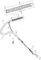
Fig. 1 , anexpandable tissue anchor 20 is provided that is configured to be anchored to a cardiac tissue wall at a target site such that a tensile force can be applied toexpandable tissue anchor 20 and thus to the cardiac tissue wall, so as to move the cardiac tissue wall at the target site relative to adjacent cardiac tissue.Expandable tissue anchor 20 comprises an elongate tissue-coupling portion 30 supported by ananchor shaft 32 at afirst end 34 of tissue-coupling portion 30. Tissue-coupling portion 30 is configured to be delivered in an unexpanded generally elongate configuration, such as described hereinbelow with reference toFig. 6A , through the cardiac tissue wall from a first side of the wall to a second side of the wall, such as described hereinbelow with reference toFigs. 6A-D . Tissue-coupling portion 30 is further configured, upon deployment, to expand, on the second side of the cardiac tissue wall, to an expanded coil (open shape) configuration, such as described hereinbelow with reference toFig. 6D , such that the expanded tissue-coupling portion 30 can be drawn tightly against the second side of the cardiac tissue wall at the target site when the tensile force is applied to tissue-coupling portion 30. Tissue-coupling portion 30 has a first stiffness. -
Expandable tissue anchor 20 further comprises anelongate tip portion 38 supported at asecond end 40 of tissue-coupling portion 30 and configured to be delivered through the cardiac tissue wall ahead of tissue-coupling portion 30, such as described hereinbelow with reference toFigs. 6A-D .Tip portion 38 has a second stiffness less than the first stiffness of the material of tissue-coupling portion 30. For example, the first stiffness of tissue-coupling portion 30 may be at least 10% greater than the second stiffness oftip portion 38, such as 20% or 30% greater. - Tissue-
coupling portion 30, once expanded on the second side of the cardiac tissue wall, such as described hereinbelow with reference toFig. 6D , comprises a configuration generally orthogonal to anchorshaft 32. For some applications, such as shown inFig. 1 ,tip portion 38 is comprises a plurality ofslits 42 that provides the lower stiffness oftip portion 38 than of tissue-coupling portion 30. For some applications, the tissue-coupling portion 30 andtip portion 38 comprise the same material, but they need not.Slits 42 may be oriented circumferentially around tip portion 38 (as shown); axially along tip portion 38 (configuration not shown); in another orientation, such as helically around tip portion 38 (configuration not shown); or in a plurality of different orientations. For some applications, such as shown inFig. 1 , tissue-coupling portion 30 andtip portion 38 are integral to one another, although they may also be discrete components fixed together. For some applications, tissue-coupling portion 30 andtip portion 38 comprise a hollow tube. In some applications,tip portion 38 is not axially compressible. For some applications,tip portion 38 has a length of at least 3 mm, such as at least 5 mm, or even at least 20 mm (but typically no more than 60 mm), which may additionally provide a clear indication of pericardial placement. - Referring to
Fig. 1 , for some applications,expandable tissue anchor 20 further comprises anelongate tension member 46 coupled to a portion of tissue-coupling portion 30. Throughelongate tension member 46, or components equivalent thereto, a tensile force can be applied to tissue-coupling portion 30 after it has been expanded to the coil open shape configuration. When applied in vivo, the tensile force may have the benefit of bringing the anchor close to the tissue wall to which it is applied. For some applications, ananchor system 50 is provided that comprisesexpandable tissue anchor 20 and atether 52 affixed to elongatetension member 46 such that the tensile force can be applied toexpandable tissue anchor 20 viatether 52 andelongate tension member 46. For some applications,anchor system 50 further comprises a second expandable tissue anchor, separate and distinct fromexpandable tissue anchor 20, such as is shown inPCT Publication WO 2016/087934 . For some applications, the second expandable tissue anchor, and additional anchors if so desired, is couplable or coupled toexpandable tissue anchor 20 by one or more tethers that includetether 52. - Referring to
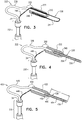
Fig. 2A , anexpandable tissue anchor 120 is provided that is generally similar toexpandable tissue anchor 20, except as described below. Anelongate tip portion 138 oftissue anchor 120 may be made of the same or similar material as a tissue-coupling portion 130 of the tissue anchor, but the average outer diameter oftip portion 138 is less than an average outer diameter of tissue-coupling portion 130 so as to provide the lower stiffness oftip portion 138 than of tissue-coupling portion 130. The difference in stiffness properties may be implemented by a difference in material and/or a difference in dimensions. For example, the average outer diameter oftip portion 138 may be at least 10% less, such as at least 20% less, than the average outer diameter of tissue-coupling portion 130. - Reference is still made to
Fig. 2A , and is additionally made toFig. 2B , which is a schematic illustration of anexpandable tissue anchor 190 that is generally similar toexpandable tissue anchor 120, except as described below. Liketissue anchor 120,tissue anchor 190 comprises a tissue-coupling portion 192,elongate tip portion 138, and ananchor shaft 194 atfirst end 34 of tissue-coupling portion 192. However, unlike in the configuration oftissue anchor 120 shown inFig. 2A ,tissue anchor 190 does not compriseelongate tension member 46. Tension is instead applied to tissue-coupling portion 192 throughanchor shaft 194, typically viatether 52. Although, for the sake of brevity, configurations of tissue anchors 20, 220, 320, and 420 are not illustrated withoutelongate tension member 46, it is to be understood thatelongate tension member 46 is optional in all of the tissue anchors described herein, and that all of the tissue anchors described herein may be provided withoutelongate tension member 46, as shown inFig. 2B fortissue anchor 190, mutatis mutandis. - Referring to
Figs. 2A and2B , for some applications, tissue-coupling portion coupling portion - Referring to
Fig. 3 , anexpandable tissue anchor 220 is provided that is generally similar toexpandable tissue anchor 20, except as described below. Anelongate tip portion 238 oftissue anchor 220 is provided as an integral distal extension of anelongate tension member 246, similar toelongate tension member 46 described hereinabove with reference toFig. 1 . In other words, a single elongate member (e.g., a solid wire or a hollow tube) defines bothelongate tension member 246 andelongate tip portion 238.Elongate tip portion 238 is supported at, and extends distally beyond, asecond end 240 of an elongate tissue-coupling portion 230. For some applications, as shown,elongate tip portion 238 is shaped as aclosed loop 244, with adistal end 248 ofelongate tension member 246 fixed to elongate tissue-coupling portion 230 near asecond end 240 of the tissue-coupling portion. Typically, the average outer diameter oftip portion 238 is less than an average outer diameter of tissue-coupling portion 230 (e.g., at least 10% less, such as at least 20% less), so as to provide at least a portion of the lower stiffness oftip portion 238 than of tissue-coupling portion 230. - In some configurations, elongate tissue-
coupling portion 230 comprises a narrowproximal portion 236 and a distal bullet head 222 (shown in cross section inFig. 3 ), which is fixed to a distal end ofproximal portion 236, and has, at a widest longitudinal site alongbullet head 222, a greatest outer cross-sectional area that equals at least 150% (e.g., at least 200%, or at least 300%) of an average outer cross-sectional area ofproximal portion 236. (The cross-sectional area ofbullet head 222 is measured perpendicular to a central longitudinal axis of the bullet head. Similarly, the cross-sectional area ofproximal portion 236 is measured perpendicular to a central longitudinal axis ofproximal portion 236.) Typically, a distal end ofdistal bullet head 222 definessecond end 240 of elongate tissue-coupling portion 230. -
Bullet head 222 may increase the surface area of tissue-coupling portion 230 for pressing againstmyocardial tissue wall 60, described hereinbelow with reference toFigs. 6A-D , which may increase stability when force is applied to tissue-coupling portion 230.Bullet head 222 may also serve as a crimp to securedistal end 248 ofelongate tension member 246 to elongate tissue-coupling portion 230. Typically, a portion ofelongate tension member 246 passes through a channel defined throughbullet head 222. Alternatively, the greatest outer cross-sectional area ofbullet head 222 equals less than 150% of the average outer cross-sectional area ofproximal portion 236, in whichconfiguration bullet head 222 may serve only as a crimp for securingdistal end 248 ofelongate tension member 246 to elongate tissue-coupling portion 230. - Referring to
Fig. 4 , anexpandable tissue anchor 320 is provided that is generally similar toexpandable tissue anchor 120, except as described below. Anelongate tip portion 338 oftissue anchor 320 is supported at asecond end 340 of an elongate tissue-coupling portion 330 oftissue anchor 320, and may be made of the same or similar material as tissue-coupling portion 330, but the average outer diameter of acore wire 356 ofelongate tip portion 338 is typically less than an average outer diameter of tissue-coupling portion 330 so as to provide the lower stiffness oftip portion 338 than of tissue-coupling portion 330. The difference in stiffness properties may be implemented by a difference in material and/or a difference in dimensions. For example, the average outer diameter oftip portion 338 may be at least 10% less, such as at least 20% less, than the average outer diameter of tissue-coupling portion 330. - For some applications,
tip portion 338 comprisescore wire 356 and acoil wire 354 wound aroundcore wire 356.Core wire 356 may, for example, comprise Nitinol, andcoil wire 354 may, for example, comprise a platinum-iridium alloy, and is typically radiopaque, such as for visualization under fluoroscopy. - In some configurations, elongate tissue-
coupling portion 330 comprises a narrowproximal portion 336 and a distal bullet head 322 (shown in cross section inFig. 4 ), which is fixed to a distal end ofproximal portion 336, and has, at a widest longitudinal site alongbullet head 322, a greatest outer cross-sectional area that equals at least 150% (e.g., at least 200%, or at least 300%) of an average outer cross-sectional area ofproximal portion 336. (The cross-sectional area ofbullet head 322 is measured perpendicular to a central longitudinal axis of the bullet head. Similarly, the cross-sectional area ofproximal portion 336 is measured perpendicular to a central longitudinal axis ofproximal portion 336.) A distal end ofdistal bullet head 322 definessecond end 340 of elongate tissue-coupling portion 330. -
Bullet head 322 may increase the surface area of tissue-coupling portion 330 for pressing againstmyocardial tissue wall 60, described hereinbelow with reference toFigs. 6A-D , which may increase stability when force is applied to tissue-coupling portion 330.Bullet head 322 also serves as a crimp to securetip portion 338 to elongate tissue-coupling portion 330. Alternatively, the greatest outer cross-sectional area ofbullet head 322 equals less than 150% of the average outer cross-sectional area ofproximal portion 336, in whichconfiguration bullet head 322 may serve only as a crimp for securingtip portion 338 to elongate tissue-coupling portion 330. - Optionally,
tissue anchor 320 further comprises anelongate tension member 346, similar toelongate tension member 46 described hereinabove with reference toFig. 1 . - Referring to
Fig. 5 , anexpandable tissue anchor 420 is provided that is generally similar toexpandable tissue anchor 320, except as described below. Anelongate tip portion 438 oftissue anchor 420 is supported at asecond end 440 of an elongate tissue-coupling portion 430 oftissue anchor 420, and may be made of the same or similar material as tissue-coupling portion 430, but the average outer diameter of acore wire 456 ofelongate tip portion 438 is typically less than an average outer diameter of tissue-coupling portion 430 so as to provide the lower stiffness oftip portion 438 than of tissue-coupling portion 430. The difference in stiffness properties may be implemented by a difference in material and/or a difference in dimensions. For example, the average outer diameter oftip portion 438 may be at least 10% less, such as at least 20% less, than the average outer diameter of tissue-coupling portion 430. - For some applications, elongate tissue-
coupling portion 430 comprises a narrowproximal portion 436, andtip portion 438 comprisescore wire 456 that is an integral distal extension ofproximal portion 436 of tissue-coupling portion 430.Proximal portion 436 narrows at a taperingportion 458 to providenarrower core wire 456, as described above. - For some applications,
tip portion 438 further comprises acoil wire 454 wound aroundcore wire 456.Core wire 456 may, for example, comprise Nitinol, andcoil wire 454 may, for example, comprise a platinum-iridium alloy, and is typically radiopaque. - In some configurations, elongate tissue-
coupling portion 430 further comprises a distal bullet head 422 (shown in cross section inFig. 5 ), which is fixed to a distal end ofproximal portion 436, and has, at a widest longitudinal site alongbullet head 422, a greatest outer cross-sectional area that equals at least 150% (e.g., at least 200%, or at least 300%) of an average outer cross-sectional area ofproximal portion 436. (The cross-sectional area ofbullet head 422 is measured perpendicular to a central longitudinal axis of the bullet head. Similarly, the cross-sectional area ofproximal portion 436 is measured perpendicular to a central longitudinal axis ofproximal portion 436.) A distal end ofdistal bullet head 422 definessecond end 440 of elongate tissue-coupling portion 430. -
Bullet head 422 may increase the surface area of tissue-coupling portion 430 for pressing againstmyocardial tissue wall 60, described hereinbelow with reference toFigs. 6A-D , which may increase stability when force is applied to tissue-coupling portion 430.Bullet head 422 may also serve as a crimp to securecoil wire 454 oftip portion 438 to elongate tissue-coupling portion 430. Alternatively, the greatest outer cross-sectional area ofbullet head 422 equals less than 150% of the average outer cross-sectional area ofwire 436, in whichconfiguration bullet head 422 may serve only as a crimp for securingcoil wire 454 to elongate tissue-coupling portion 430. - Optionally,
tissue anchor 420 further comprises anelongate tension member 446, similar toelongate tension member 46 described hereinabove with reference toFig. 1 . - For some applications,
tip portion 438 has a length L, distally beyondsecond end 440 of tissue-coupling portion 430, of at least 3 mm, such as at least 5 mm, or even at least 20 mm (but typically no more than 60 mm), which may additionally provide a clear indication of pericardial placement. (Tip portion 438 oftissue anchor 320, described hereinabove with reference toFig. 4 , may also have this length.) - Referring to
Figs. 3-5 , for some applications, narrowproximal portion proximal portion - Still referring to
Figs. 3-5 , for some applications,elongate tip portion pericardial cavity 80, such as described hereinbelow with reference toFigs. 6A-D . - Reference is now made to
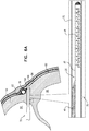
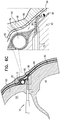
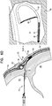
Figs. 6A-D , which are schematic illustrations of a method of deployingexpandable tissue anchor 20 through amyocardial tissue wall 60. Although inFigs. 6A-D expandable tissue anchor 20 is shown deployed through a myocardial tissue wall,expandable tissue anchor 20 may also be deployed through other cardiac tissue walls, such as the interatrial septum, either at or not at the fossa ovalis, or through other non-cardiac tissue walls. Indeed, the tissue anchors described herein may be deployed in any number of bodily locations where it is desired to anchor into or behind tissue for purposes of moving such tissue relative to adjacent tissue. The method ofFigs. 6A-D may also be used for deployingexpandable tissue anchor 120,tissue anchor 190,tissue anchor 220,tissue anchor 320, andtissue anchor 420, described hereinabove with reference toFigs. 2A ,2B ,3, 4, and 5 , respectively. - As shown in
Fig. 6A ,expandable tissue anchor 20 is delivered to a target site, such as a cardiac chamber, in an unexpanded generally elongate configuration within adeployment tool 70, which comprises ahollow needle 72. The cardiac chamber may be a right atrium 64 (as shown), a right ventricle 66 (configuration not shown), a left atrium (configuration not shown), or a left ventricle (configuration not shown). In one application,hollow needle 72 is used to puncture through a first side of amyocardial tissue wall 60 and visceral pericardium 82 (which is part of the epicardium), avoiding vasculature such as the right coronary artery (RCA) 78. Thedeployment tool 70 is then further directed into thepericardial cavity 80 betweenvisceral pericardium 82 andparietal pericardium 84, carefully avoiding puncturingparietal pericardium 84 andfibrous pericardium 86. - As shown in
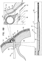
Fig. 6B , for some applications,hollow needle 72 is withdrawn slightly, exposing some or all of the tip portion of theexpandable tissue anchor 20 within a bore created throughmyocardial tissue wall 60 by thehollow needle 72. As shown inFig. 6C ,elongate tip portion 38 ofexpandable tissue anchor 20 is delivered throughmyocardial tissue wall 60 ahead of tissue-coupling portion 30.Tip portion 38 can be directed, upon deployment inpericardial cavity 80 on the second side ofmyocardial tissue wall 60, intopericardial cavity 80 ahead of tissue-coupling portion 30, generally alongside and against pericardial tissue surrounding the myocardial tissue wall, without penetrating the pericardial tissue (particularly,parietal pericardium 84 and fibrous pericardium 86).Tip portion 38 is not stiff enough to inadvertently puncture the pericardial tissue. - As shown in
Fig. 6D , tissue-coupling portion 30 ofexpandable tissue anchor 20 is delivered throughmyocardial tissue wall 60 and intopericardial cavity 80 followingelongate tip portion 38.Elongate tip portion 38 directs tissue-coupling portion 30 generally alongside and against the pericardial tissue, thereby preventing the stiffer tissue-coupling portion 30 from puncturing the pericardial tissue (particularly,parietal pericardium 84 and fibrous pericardium 86). Tissue-coupling portion 30 expands to the coil open shape configuration on the second site ofmyocardial tissue wall 60, thereby anchoringexpandable tissue anchor 20 tomyocardial tissue wall 60. - Once
expandable tissue anchor 20 has been anchored tomyocardial tissue wall 60 at the target site, a tensile force is applied usingtether 52 toexpandable tissue anchor 20 and thus tomyocardial tissue wall 60, so as to movemyocardial tissue wall 60 at the target site relative to adjacent cardiac tissue. For some applications, such motion can have the benefit of altering the geometry of a nearby cardiac valve, such as the tricuspid valve or the mitral valve. - The following applications, which are assigned to the assignee of the present patent, disclose techniques that may be combined with embodiments of the present invention:
US Patent 8,475,525 to Maisano et al. ;US Patent 8,961,596 to Maisano et al. ;US Patent 8,961,594 to Maisano et al. ;PCT Publication WO 2011/089601 ;US Patent 9,241,702 to Maisano et al. PCT Publication WO 2013/011502 ;US Provisional Application 61/750,427, filed January 9, 2013 US Provisional Application 61/783,224, filed March 14, 2013 PCT Publication WO 2013/179295 ;US Provisional Application 61/897,491, filed October 30, 2013 US Provisional Application 61/897,509, filed October 30, 2013 US Patent 9,307,980 to Gilmore et al. PCT Publication WO 2014/108903 ;PCT Publication WO 2014/141239 ;US Provisional Application 62/014,397, filed June 19, 2014 PCT Publication WO 2015/063580 ;US Patent Application Publication 2015/0119936 ;US Provisional Application 62/086,269, filed December 2, 2014 US Provisional Application 62/131,636, filed March 11, 2015 US Provisional Application 62/167,660, filed May 28, 2015 PCT Publication WO 2015/193728 ;PCT Publication WO 2016/087934 ;US Patent Application Publication 2016/0242762 ;PCT Publication WO 2016/189391 ; andUS Patent Application Publication 2016/0262741 . - It will be appreciated by persons skilled in the art that the present invention is not limited to what has been particularly shown and described hereinabove. Rather, the scope of the present invention is defined by the claims, and may include both combinations and subcombinations of the various features described hereinabove, as well as variations and modifications thereof that are not in the prior art, which would occur to persons skilled in the art upon reading the foregoing description.
Claims (16)
- An expandable tissue anchor (20, 120, 190, 220, 320, 420) configured to be delivered to a cardiac chamber in an unexpanded generally elongate configuration within a deployment tool (70), the expandable tissue anchor (20, 120, 190, 220, 320, 420) configured to be anchored to a cardiac tissue wall at a target site such that a tensile force can be applied to the expandable tissue anchor (20, 120, 190, 220, 320, 420) and thus to the cardiac tissue wall, once the expandable tissue anchor (20, 120, 190, 220, 320, 420) is deployed, so as to move the cardiac tissue wall at the target site relative to adjacent cardiac tissue, the expandable tissue anchor (20, 120, 190, 220, 320, 420) comprising:an elongate tissue-coupling portion (30, 130, 192, 230, 330, 430) supported by an anchor shaft (32, 194) at a first end (34) of the tissue-coupling portion (30, 130, 192, 230, 330, 430), the tissue-coupling portion (30, 130, 192, 230, 330, 430) configured to be delivered in an unexpanded generally elongate configuration through the cardiac tissue wall from a first side of the wall to a second side of the wall, the tissue-coupling portion (30, 130, 192, 230, 330, 430) further configured to expand, on the second side of the cardiac tissue wall, to an expanded coil open shape configuration generally orthogonal to the anchor shaft (32, 194), such that the expanded tissue-coupling portion (30, 130, 192, 230, 330, 430) can be drawn tightly against the second side of the cardiac tissue wall at the target site when the tensile force is applied to the tissue-coupling portion (30, 130, 192, 230, 330, 430), the tissue-coupling portion (30, 130, 192, 230, 330, 430) having a first stiffness;
characterized byan elongate tip portion (38, 138, 238, 338, 438) supported at a second end (40, 240, 340, 440) of the tissue-coupling portion (30, 130, 192, 230, 330, 430) and configured to be delivered through the cardiac tissue wall ahead of the tissue-coupling portion (30, 130, 192, 230, 330, 430), the tip portion (38, 138, 238, 338, 438) having a second stiffness less than the first stiffness. - The expandable tissue anchor (20, 120, 190, 220, 320, 420) according to Claim 1, wherein the tip portion (38, 138, 238, 338, 438) is axially fixed with respect to the tissue-coupling portion (30, 130, 192, 230, 330, 430).
- The expandable tissue anchor (20, 120, 190, 320, 420) according to Claim 1, wherein the tip portion (38, 138, 338, 438) is not axially compressible.
- The expandable tissue anchor (20, 120, 190, 220, 320, 420) according to Claim 1, wherein the first stiffness of the tissue-coupling portion (30, 130, 192, 230, 330, 430) is at least 10% greater than the second stiffness of the tip portion (38, 138, 238, 338, 438).
- The expandable tissue anchor (20, 120, 190, 220, 320, 420) according to Claim 1, wherein the tip portion (38, 138, 238, 338, 438) has a length of at least 3 mm.
- The expandable tissue anchor (20) according to Claim 1, wherein the tip portion (38) comprises a plurality of slits (42) that provides the lower second stiffness of the tip portion (38).
- The expandable tissue anchor (120, 190) according to Claim 1, wherein an average outer diameter of the tip portion (138) is less than an average outer diameter of the tissue-coupling portion (130, 192) so as to provide the lower second stiffness of the tip portion (138).
- The expandable tissue anchor (20, 120, 190, 220, 320, 420) according to Claim 1, wherein the tip portion (38, 138, 238, 338, 438) comprises a material different from that of the tissue-coupling portion (30, 130, 192, 230, 330, 430) so as to provide the lower second stiffness of the tip portion (38, 138, 238, 338, 438) relative to the first stiffness of the tissue-coupling portion (30, 130, 192, 230, 330, 430).
- The expandable tissue anchor (20, 420) according to any one of Claims 1-8, wherein the tissue-coupling portion (30, 430) and the tip portion (38, 438) are integral to one another.
- The expandable tissue anchor (20) according to Claim 9, wherein the tissue-coupling portion (30) and the tip portion (38) comprise a hollow tube.
- The expandable tissue anchor (320, 420) according to any one of Claims 1-5 or 8-9, wherein the tip portion (338, 438) comprises a core wire (356, 456) and a coil wire (354, 454) wound around the core wire (356, 456).
- The expandable tissue anchor (20, 120, 220, 320, 420) according to any one of Claims 1-11, further comprising an elongate tension member (46, 246, 346, 446) coupled to a portion of the tissue-coupling portion (30, 130, 230, 330, 430) such that the tensile force can be applied to the tissue-coupling portion (30, 130, 230, 330, 430) after it has been expanded to the coil open shape configuration.
- The expandable tissue anchor (220) according to Claim 12,
wherein the tip portion (238) is an integral distal extension of the elongate tension member (246), and
wherein the tip portion (238) is shaped as a closed loop (244), with a distal end (248) of the elongate tension member (246) fixed to the tissue-coupling portion (230) near the second end (240) of the tissue-coupling portion (230). - An anchor system (50) comprising the expandable tissue anchor (20, 120, 220, 320, 420) according to Claim 12, wherein the anchor system (50) further comprises a tether (52) affixed to the elongate tension member (46, 246, 346, 446) such that the tensile force can be applied to the expandable tissue anchor (20, 120, 220, 320, 420) via the tether (52) and the elongate tension member (46, 246, 346, 446).
- An anchor system (50) comprising the expandable tissue anchor (20, 120, 220, 320, 420) according to Claim 12, further comprising a second expandable tissue anchor, separate and distinct from the expandable tissue anchor (20, 120, 220, 320, 420).
- The expandable tissue anchor (220, 320, 420) according to any one of Claims 1-5, 8-9, and 11-13 wherein the tissue-coupling portion (230, 330, 430) comprises a proximal portion (236, 336, 436) and a distal bullet head (222, 322, 422), which is fixed to a distal end of the proximal portion (236, 336, 436), and has, at a widest longitudinal site along the bullet head (222, 322, 422), a greatest outer cross-sectional area that equals at least 150% of an average outer cross-sectional area of the proximal portion (236, 336, 436).
Applications Claiming Priority (3)
| Application Number | Priority Date | Filing Date | Title |
|---|---|---|---|
| US201662376685P | 2016-08-18 | 2016-08-18 | |
| ILPCT/IL2017/050771 | 2017-07-10 | ||
| PCT/US2017/047442 WO2018035378A1 (en) | 2016-08-18 | 2017-08-17 | Tissue anchors with flexible tips for insertion into the pericardial cavity |
Publications (2)
| Publication Number | Publication Date |
|---|---|
| EP3432806A1 EP3432806A1 (en) | 2019-01-30 |
| EP3432806B1 true EP3432806B1 (en) | 2019-10-02 |
Family
ID=59702896
Family Applications (1)
| Application Number | Title | Priority Date | Filing Date |
|---|---|---|---|
| EP17758020.6A Active EP3432806B1 (en) | 2016-08-18 | 2017-08-17 | Tissue anchors with flexible tips for insertion into the pericardial cavity |
Country Status (5)
| Country | Link |
|---|---|
| US (1) | US20190240024A1 (en) |
| EP (1) | EP3432806B1 (en) |
| JP (1) | JP6632047B2 (en) |
| CN (1) | CN109640836A (en) |
| WO (1) | WO2018035378A1 (en) |
Cited By (13)
| Publication number | Priority date | Publication date | Assignee | Title |
|---|---|---|---|---|
| US10856984B2 (en) | 2017-08-25 | 2020-12-08 | Neovasc Tiara Inc. | Sequentially deployed transcatheter mitral valve prosthesis |
| US10940001B2 (en) | 2012-05-30 | 2021-03-09 | Neovasc Tiara Inc. | Methods and apparatus for loading a prosthesis onto a delivery system |
| US11311376B2 (en) | 2019-06-20 | 2022-04-26 | Neovase Tiara Inc. | Low profile prosthetic mitral valve |
| US11357622B2 (en) | 2016-01-29 | 2022-06-14 | Neovase Tiara Inc. | Prosthetic valve for avoiding obstruction of outflow |
| US11389291B2 (en) | 2013-04-04 | 2022-07-19 | Neovase Tiara Inc. | Methods and apparatus for delivering a prosthetic valve to a beating heart |
| US11413139B2 (en) | 2011-11-23 | 2022-08-16 | Neovasc Tiara Inc. | Sequentially deployed transcatheter mitral valve prosthesis |
| US11419720B2 (en) | 2010-05-05 | 2022-08-23 | Neovasc Tiara Inc. | Transcatheter mitral valve prosthesis |
| US11464631B2 (en) | 2016-11-21 | 2022-10-11 | Neovasc Tiara Inc. | Methods and systems for rapid retraction of a transcatheter heart valve delivery system |
| US11491006B2 (en) | 2019-04-10 | 2022-11-08 | Neovasc Tiara Inc. | Prosthetic valve with natural blood flow |
| US11497602B2 (en) | 2012-02-14 | 2022-11-15 | Neovasc Tiara Inc. | Methods and apparatus for engaging a valve prosthesis with tissue |
| US11602429B2 (en) | 2019-04-01 | 2023-03-14 | Neovasc Tiara Inc. | Controllably deployable prosthetic valve |
| US11737872B2 (en) | 2018-11-08 | 2023-08-29 | Neovasc Tiara Inc. | Ventricular deployment of a transcatheter mitral valve prosthesis |
| US11779742B2 (en) | 2019-05-20 | 2023-10-10 | Neovasc Tiara Inc. | Introducer with hemostasis mechanism |
Families Citing this family (9)
| Publication number | Priority date | Publication date | Assignee | Title |
|---|---|---|---|---|
| EP3284412A1 (en) | 2014-12-02 | 2018-02-21 | 4Tech Inc. | Off-center tissue anchors |
| US9877833B1 (en) | 2016-12-30 | 2018-01-30 | Pipeline Medical Technologies, Inc. | Method and apparatus for transvascular implantation of neo chordae tendinae |
| US10925731B2 (en) | 2016-12-30 | 2021-02-23 | Pipeline Medical Technologies, Inc. | Method and apparatus for transvascular implantation of neo chordae tendinae |
| US11083580B2 (en) | 2016-12-30 | 2021-08-10 | Pipeline Medical Technologies, Inc. | Method of securing a leaflet anchor to a mitral valve leaflet |
| CA3067813C (en) * | 2017-06-30 | 2023-09-26 | Giora WEISZ | Multi-dimensional navigation within a body chamber |
| WO2019074815A1 (en) | 2017-10-10 | 2019-04-18 | 4Tech Inc. | Force-distributing anchor system |
| CN111107795A (en) | 2018-02-09 | 2020-05-05 | 4科技有限公司 | Frustoconical hemostatic sealing element |
| CN113286566A (en) | 2018-12-12 | 2021-08-20 | 管道医疗技术公司 | Method and apparatus for mitral chordae repair |
| EP3902484A1 (en) | 2018-12-24 | 2021-11-03 | 4 Tech Inc. | Self-locking tissue anchors |
Family Cites Families (20)
| Publication number | Priority date | Publication date | Assignee | Title |
|---|---|---|---|---|
| US6165183A (en) * | 1998-07-15 | 2000-12-26 | St. Jude Medical, Inc. | Mitral and tricuspid valve repair |
| EP2078498B1 (en) * | 1999-04-09 | 2010-12-22 | Evalve, Inc. | Apparatus for cardiac valve repair |
| US6752813B2 (en) | 1999-04-09 | 2004-06-22 | Evalve, Inc. | Methods and devices for capturing and fixing leaflets in valve repair |
| US8632590B2 (en) * | 1999-10-20 | 2014-01-21 | Anulex Technologies, Inc. | Apparatus and methods for the treatment of the intervertebral disc |
| US6652555B1 (en) * | 1999-10-27 | 2003-11-25 | Atritech, Inc. | Barrier device for covering the ostium of left atrial appendage |
| US20050107811A1 (en) * | 2002-06-13 | 2005-05-19 | Guided Delivery Systems, Inc. | Delivery devices and methods for heart valve repair |
| US8475525B2 (en) | 2010-01-22 | 2013-07-02 | 4Tech Inc. | Tricuspid valve repair using tension |
| US9307980B2 (en) | 2010-01-22 | 2016-04-12 | 4Tech Inc. | Tricuspid valve repair using tension |
| US8961596B2 (en) | 2010-01-22 | 2015-02-24 | 4Tech Inc. | Method and apparatus for tricuspid valve repair using tension |
| WO2013011502A2 (en) | 2011-07-21 | 2013-01-24 | 4Tech Inc. | Method and apparatus for tricuspid valve repair using tension |
| WO2013101923A1 (en) * | 2011-12-29 | 2013-07-04 | St. Jude Medical, Atrial Fibrillation Division, Inc. | System for optimized coupling of ablation catheters to body tissues and evaluation of lesions formed by the catheters |
| US8961594B2 (en) | 2012-05-31 | 2015-02-24 | 4Tech Inc. | Heart valve repair system |
| US9788948B2 (en) | 2013-01-09 | 2017-10-17 | 4 Tech Inc. | Soft tissue anchors and implantation techniques |
| US9907681B2 (en) | 2013-03-14 | 2018-03-06 | 4Tech Inc. | Stent with tether interface |
| US10022114B2 (en) | 2013-10-30 | 2018-07-17 | 4Tech Inc. | Percutaneous tether locking |
| US10052095B2 (en) | 2013-10-30 | 2018-08-21 | 4Tech Inc. | Multiple anchoring-point tension system |
| EP3062709A2 (en) | 2013-10-30 | 2016-09-07 | 4Tech Inc. | Multiple anchoring-point tension system |
| EP3157607B1 (en) | 2014-06-19 | 2019-08-07 | 4Tech Inc. | Cardiac tissue cinching |
| EP3284412A1 (en) | 2014-12-02 | 2018-02-21 | 4Tech Inc. | Off-center tissue anchors |
| WO2016189391A2 (en) | 2015-05-28 | 2016-12-01 | 4Tech Inc. | Off-center tissue anchors with tension members |
-
2017
- 2017-08-17 WO PCT/US2017/047442 patent/WO2018035378A1/en active Application Filing
- 2017-08-17 CN CN201780043418.2A patent/CN109640836A/en active Pending
- 2017-08-17 US US16/326,332 patent/US20190240024A1/en not_active Abandoned
- 2017-08-17 EP EP17758020.6A patent/EP3432806B1/en active Active
- 2017-08-17 JP JP2019508854A patent/JP6632047B2/en not_active Expired - Fee Related
Non-Patent Citations (1)
| Title |
|---|
| None * |
Cited By (17)
| Publication number | Priority date | Publication date | Assignee | Title |
|---|---|---|---|---|
| US11419720B2 (en) | 2010-05-05 | 2022-08-23 | Neovasc Tiara Inc. | Transcatheter mitral valve prosthesis |
| US11413139B2 (en) | 2011-11-23 | 2022-08-16 | Neovasc Tiara Inc. | Sequentially deployed transcatheter mitral valve prosthesis |
| US11497602B2 (en) | 2012-02-14 | 2022-11-15 | Neovasc Tiara Inc. | Methods and apparatus for engaging a valve prosthesis with tissue |
| US10940001B2 (en) | 2012-05-30 | 2021-03-09 | Neovasc Tiara Inc. | Methods and apparatus for loading a prosthesis onto a delivery system |
| US11617650B2 (en) | 2012-05-30 | 2023-04-04 | Neovasc Tiara Inc. | Methods and apparatus for loading a prosthesis onto a delivery system |
| US11389294B2 (en) | 2012-05-30 | 2022-07-19 | Neovasc Tiara Inc. | Methods and apparatus for loading a prosthesis onto a delivery system |
| US11389291B2 (en) | 2013-04-04 | 2022-07-19 | Neovase Tiara Inc. | Methods and apparatus for delivering a prosthetic valve to a beating heart |
| US11357622B2 (en) | 2016-01-29 | 2022-06-14 | Neovase Tiara Inc. | Prosthetic valve for avoiding obstruction of outflow |
| US11464631B2 (en) | 2016-11-21 | 2022-10-11 | Neovasc Tiara Inc. | Methods and systems for rapid retraction of a transcatheter heart valve delivery system |
| US10856984B2 (en) | 2017-08-25 | 2020-12-08 | Neovasc Tiara Inc. | Sequentially deployed transcatheter mitral valve prosthesis |
| US11793640B2 (en) | 2017-08-25 | 2023-10-24 | Neovasc Tiara Inc. | Sequentially deployed transcatheter mitral valve prosthesis |
| US11737872B2 (en) | 2018-11-08 | 2023-08-29 | Neovasc Tiara Inc. | Ventricular deployment of a transcatheter mitral valve prosthesis |
| US11602429B2 (en) | 2019-04-01 | 2023-03-14 | Neovasc Tiara Inc. | Controllably deployable prosthetic valve |
| US11491006B2 (en) | 2019-04-10 | 2022-11-08 | Neovasc Tiara Inc. | Prosthetic valve with natural blood flow |
| US11779742B2 (en) | 2019-05-20 | 2023-10-10 | Neovasc Tiara Inc. | Introducer with hemostasis mechanism |
| US11311376B2 (en) | 2019-06-20 | 2022-04-26 | Neovase Tiara Inc. | Low profile prosthetic mitral valve |
| US11931254B2 (en) | 2019-06-20 | 2024-03-19 | Neovasc Tiara Inc. | Low profile prosthetic mitral valve |
Also Published As
| Publication number | Publication date |
|---|---|
| WO2018035378A1 (en) | 2018-02-22 |
| JP2019524341A (en) | 2019-09-05 |
| EP3432806A1 (en) | 2019-01-30 |
| US20190240024A1 (en) | 2019-08-08 |
| CN109640836A (en) | 2019-04-16 |
| JP6632047B2 (en) | 2020-01-15 |
Similar Documents
| Publication | Publication Date | Title |
|---|---|---|
| EP3432806B1 (en) | Tissue anchors with flexible tips for insertion into the pericardial cavity | |
| EP3634255B1 (en) | Tissue anchor with tether stop | |
| US11819411B2 (en) | Annuloplasty and tissue anchor technologies | |
| US20200229820A1 (en) | Multi-window guide tunnel | |
| US9585754B2 (en) | Implant for treatment of a heart valve, in particular a mitral valve, material including such an implant, and material for insertion thereof | |
| CN108601655B (en) | Mitral valve transition prosthesis | |
| EP4032501A1 (en) | Annuloplasty implant | |
| EP2819619B1 (en) | Percutaneous annuloplasty system with anterior-posterior adjustment | |
| US8715342B2 (en) | Annuloplasty ring with intra-ring anchoring | |
| RU2019121972A (en) | Method and device for transvascular implantation of tendon neochord | |
| WO2019013994A1 (en) | Tissue anchors with load-bearing features | |
| US20200360001A1 (en) | Frustoconical Hemostatic Sealing Elements | |
| EP3661428B1 (en) | Tissue anchors with hemostasis features | |
| US20220071616A1 (en) | Self-Locking Tissue Anchors | |
| US20240138988A1 (en) | Annuloplasty and tissue anchor technologies | |
| WO2024092059A1 (en) | Mitral valve leaflet repair system |
Legal Events
| Date | Code | Title | Description |
|---|---|---|---|
| STAA | Information on the status of an ep patent application or granted ep patent |
Free format text: STATUS: UNKNOWN |
|
| STAA | Information on the status of an ep patent application or granted ep patent |
Free format text: STATUS: THE INTERNATIONAL PUBLICATION HAS BEEN MADE |
|
| PUAI | Public reference made under article 153(3) epc to a published international application that has entered the european phase |
Free format text: ORIGINAL CODE: 0009012 |
|
| STAA | Information on the status of an ep patent application or granted ep patent |
Free format text: STATUS: REQUEST FOR EXAMINATION WAS MADE |
|
| 17P | Request for examination filed |
Effective date: 20181023 |
|
| AK | Designated contracting states |
Kind code of ref document: A1 Designated state(s): AL AT BE BG CH CY CZ DE DK EE ES FI FR GB GR HR HU IE IS IT LI LT LU LV MC MK MT NL NO PL PT RO RS SE SI SK SM TR |
|
| AX | Request for extension of the european patent |
Extension state: BA ME |
|
| GRAP | Despatch of communication of intention to grant a patent |
Free format text: ORIGINAL CODE: EPIDOSNIGR1 |
|
| STAA | Information on the status of an ep patent application or granted ep patent |
Free format text: STATUS: GRANT OF PATENT IS INTENDED |
|
| DAV | Request for validation of the european patent (deleted) | ||
| DAX | Request for extension of the european patent (deleted) | ||
| INTG | Intention to grant announced |
Effective date: 20190724 |
|
| GRAS | Grant fee paid |
Free format text: ORIGINAL CODE: EPIDOSNIGR3 |
|
| GRAA | (expected) grant |
Free format text: ORIGINAL CODE: 0009210 |
|
| STAA | Information on the status of an ep patent application or granted ep patent |
Free format text: STATUS: THE PATENT HAS BEEN GRANTED |
|
| AK | Designated contracting states |
Kind code of ref document: B1 Designated state(s): AL AT BE BG CH CY CZ DE DK EE ES FI FR GB GR HR HU IE IS IT LI LT LU LV MC MK MT NL NO PL PT RO RS SE SI SK SM TR |
|
| REG | Reference to a national code |
Ref country code: GB Ref legal event code: FG4D |
|
| REG | Reference to a national code |
Ref country code: CH Ref legal event code: EP Ref country code: AT Ref legal event code: REF Ref document number: 1185317 Country of ref document: AT Kind code of ref document: T Effective date: 20191015 |
|
| REG | Reference to a national code |
Ref country code: DE Ref legal event code: R096 Ref document number: 602017007508 Country of ref document: DE |
|
| REG | Reference to a national code |
Ref country code: IE Ref legal event code: FG4D |
|
| REG | Reference to a national code |
Ref country code: NL Ref legal event code: FP |
|
| REG | Reference to a national code |
Ref country code: LT Ref legal event code: MG4D |
|
| REG | Reference to a national code |
Ref country code: AT Ref legal event code: MK05 Ref document number: 1185317 Country of ref document: AT Kind code of ref document: T Effective date: 20191002 |
|
| PG25 | Lapsed in a contracting state [announced via postgrant information from national office to epo] |
Ref country code: LT Free format text: LAPSE BECAUSE OF FAILURE TO SUBMIT A TRANSLATION OF THE DESCRIPTION OR TO PAY THE FEE WITHIN THE PRESCRIBED TIME-LIMIT Effective date: 20191002 Ref country code: AT Free format text: LAPSE BECAUSE OF FAILURE TO SUBMIT A TRANSLATION OF THE DESCRIPTION OR TO PAY THE FEE WITHIN THE PRESCRIBED TIME-LIMIT Effective date: 20191002 Ref country code: PL Free format text: LAPSE BECAUSE OF FAILURE TO SUBMIT A TRANSLATION OF THE DESCRIPTION OR TO PAY THE FEE WITHIN THE PRESCRIBED TIME-LIMIT Effective date: 20191002 Ref country code: GR Free format text: LAPSE BECAUSE OF FAILURE TO SUBMIT A TRANSLATION OF THE DESCRIPTION OR TO PAY THE FEE WITHIN THE PRESCRIBED TIME-LIMIT Effective date: 20200103 Ref country code: ES Free format text: LAPSE BECAUSE OF FAILURE TO SUBMIT A TRANSLATION OF THE DESCRIPTION OR TO PAY THE FEE WITHIN THE PRESCRIBED TIME-LIMIT Effective date: 20191002 Ref country code: PT Free format text: LAPSE BECAUSE OF FAILURE TO SUBMIT A TRANSLATION OF THE DESCRIPTION OR TO PAY THE FEE WITHIN THE PRESCRIBED TIME-LIMIT Effective date: 20200203 Ref country code: FI Free format text: LAPSE BECAUSE OF FAILURE TO SUBMIT A TRANSLATION OF THE DESCRIPTION OR TO PAY THE FEE WITHIN THE PRESCRIBED TIME-LIMIT Effective date: 20191002 Ref country code: BG Free format text: LAPSE BECAUSE OF FAILURE TO SUBMIT A TRANSLATION OF THE DESCRIPTION OR TO PAY THE FEE WITHIN THE PRESCRIBED TIME-LIMIT Effective date: 20200102 Ref country code: NO Free format text: LAPSE BECAUSE OF FAILURE TO SUBMIT A TRANSLATION OF THE DESCRIPTION OR TO PAY THE FEE WITHIN THE PRESCRIBED TIME-LIMIT Effective date: 20200102 Ref country code: LV Free format text: LAPSE BECAUSE OF FAILURE TO SUBMIT A TRANSLATION OF THE DESCRIPTION OR TO PAY THE FEE WITHIN THE PRESCRIBED TIME-LIMIT Effective date: 20191002 Ref country code: SE Free format text: LAPSE BECAUSE OF FAILURE TO SUBMIT A TRANSLATION OF THE DESCRIPTION OR TO PAY THE FEE WITHIN THE PRESCRIBED TIME-LIMIT Effective date: 20191002 |
|
| PG25 | Lapsed in a contracting state [announced via postgrant information from national office to epo] |
Ref country code: IS Free format text: LAPSE BECAUSE OF FAILURE TO SUBMIT A TRANSLATION OF THE DESCRIPTION OR TO PAY THE FEE WITHIN THE PRESCRIBED TIME-LIMIT Effective date: 20200224 Ref country code: HR Free format text: LAPSE BECAUSE OF FAILURE TO SUBMIT A TRANSLATION OF THE DESCRIPTION OR TO PAY THE FEE WITHIN THE PRESCRIBED TIME-LIMIT Effective date: 20191002 Ref country code: RS Free format text: LAPSE BECAUSE OF FAILURE TO SUBMIT A TRANSLATION OF THE DESCRIPTION OR TO PAY THE FEE WITHIN THE PRESCRIBED TIME-LIMIT Effective date: 20191002 Ref country code: CZ Free format text: LAPSE BECAUSE OF FAILURE TO SUBMIT A TRANSLATION OF THE DESCRIPTION OR TO PAY THE FEE WITHIN THE PRESCRIBED TIME-LIMIT Effective date: 20191002 |
|
| PG25 | Lapsed in a contracting state [announced via postgrant information from national office to epo] |
Ref country code: AL Free format text: LAPSE BECAUSE OF FAILURE TO SUBMIT A TRANSLATION OF THE DESCRIPTION OR TO PAY THE FEE WITHIN THE PRESCRIBED TIME-LIMIT Effective date: 20191002 |
|
| REG | Reference to a national code |
Ref country code: DE Ref legal event code: R097 Ref document number: 602017007508 Country of ref document: DE |
|
| PG2D | Information on lapse in contracting state deleted |
Ref country code: IS |
|
| PG25 | Lapsed in a contracting state [announced via postgrant information from national office to epo] |
Ref country code: RO Free format text: LAPSE BECAUSE OF FAILURE TO SUBMIT A TRANSLATION OF THE DESCRIPTION OR TO PAY THE FEE WITHIN THE PRESCRIBED TIME-LIMIT Effective date: 20191002 Ref country code: DK Free format text: LAPSE BECAUSE OF FAILURE TO SUBMIT A TRANSLATION OF THE DESCRIPTION OR TO PAY THE FEE WITHIN THE PRESCRIBED TIME-LIMIT Effective date: 20191002 Ref country code: EE Free format text: LAPSE BECAUSE OF FAILURE TO SUBMIT A TRANSLATION OF THE DESCRIPTION OR TO PAY THE FEE WITHIN THE PRESCRIBED TIME-LIMIT Effective date: 20191002 Ref country code: IS Free format text: LAPSE BECAUSE OF FAILURE TO SUBMIT A TRANSLATION OF THE DESCRIPTION OR TO PAY THE FEE WITHIN THE PRESCRIBED TIME-LIMIT Effective date: 20200202 |
|
| PLBE | No opposition filed within time limit |
Free format text: ORIGINAL CODE: 0009261 |
|
| STAA | Information on the status of an ep patent application or granted ep patent |
Free format text: STATUS: NO OPPOSITION FILED WITHIN TIME LIMIT |
|
| PG25 | Lapsed in a contracting state [announced via postgrant information from national office to epo] |
Ref country code: SK Free format text: LAPSE BECAUSE OF FAILURE TO SUBMIT A TRANSLATION OF THE DESCRIPTION OR TO PAY THE FEE WITHIN THE PRESCRIBED TIME-LIMIT Effective date: 20191002 Ref country code: SM Free format text: LAPSE BECAUSE OF FAILURE TO SUBMIT A TRANSLATION OF THE DESCRIPTION OR TO PAY THE FEE WITHIN THE PRESCRIBED TIME-LIMIT Effective date: 20191002 Ref country code: IT Free format text: LAPSE BECAUSE OF FAILURE TO SUBMIT A TRANSLATION OF THE DESCRIPTION OR TO PAY THE FEE WITHIN THE PRESCRIBED TIME-LIMIT Effective date: 20191002 |
|
| 26N | No opposition filed |
Effective date: 20200703 |
|
| PG25 | Lapsed in a contracting state [announced via postgrant information from national office to epo] |
Ref country code: SI Free format text: LAPSE BECAUSE OF FAILURE TO SUBMIT A TRANSLATION OF THE DESCRIPTION OR TO PAY THE FEE WITHIN THE PRESCRIBED TIME-LIMIT Effective date: 20191002 |
|
| PG25 | Lapsed in a contracting state [announced via postgrant information from national office to epo] |
Ref country code: MC Free format text: LAPSE BECAUSE OF FAILURE TO SUBMIT A TRANSLATION OF THE DESCRIPTION OR TO PAY THE FEE WITHIN THE PRESCRIBED TIME-LIMIT Effective date: 20191002 |
|
| REG | Reference to a national code |
Ref country code: CH Ref legal event code: PL |
|
| PG25 | Lapsed in a contracting state [announced via postgrant information from national office to epo] |
Ref country code: LI Free format text: LAPSE BECAUSE OF NON-PAYMENT OF DUE FEES Effective date: 20200831 Ref country code: LU Free format text: LAPSE BECAUSE OF NON-PAYMENT OF DUE FEES Effective date: 20200817 Ref country code: CH Free format text: LAPSE BECAUSE OF NON-PAYMENT OF DUE FEES Effective date: 20200831 |
|
| REG | Reference to a national code |
Ref country code: BE Ref legal event code: MM Effective date: 20200831 |
|
| PG25 | Lapsed in a contracting state [announced via postgrant information from national office to epo] |
Ref country code: IE Free format text: LAPSE BECAUSE OF NON-PAYMENT OF DUE FEES Effective date: 20200817 Ref country code: BE Free format text: LAPSE BECAUSE OF NON-PAYMENT OF DUE FEES Effective date: 20200831 |
|
| PGFP | Annual fee paid to national office [announced via postgrant information from national office to epo] |
Ref country code: NL Payment date: 20210729 Year of fee payment: 5 |
|
| PGFP | Annual fee paid to national office [announced via postgrant information from national office to epo] |
Ref country code: FR Payment date: 20210729 Year of fee payment: 5 |
|
| PGFP | Annual fee paid to national office [announced via postgrant information from national office to epo] |
Ref country code: GB Payment date: 20210802 Year of fee payment: 5 Ref country code: DE Payment date: 20210730 Year of fee payment: 5 |
|
| PG25 | Lapsed in a contracting state [announced via postgrant information from national office to epo] |
Ref country code: TR Free format text: LAPSE BECAUSE OF FAILURE TO SUBMIT A TRANSLATION OF THE DESCRIPTION OR TO PAY THE FEE WITHIN THE PRESCRIBED TIME-LIMIT Effective date: 20191002 Ref country code: MT Free format text: LAPSE BECAUSE OF FAILURE TO SUBMIT A TRANSLATION OF THE DESCRIPTION OR TO PAY THE FEE WITHIN THE PRESCRIBED TIME-LIMIT Effective date: 20191002 Ref country code: CY Free format text: LAPSE BECAUSE OF FAILURE TO SUBMIT A TRANSLATION OF THE DESCRIPTION OR TO PAY THE FEE WITHIN THE PRESCRIBED TIME-LIMIT Effective date: 20191002 |
|
| PG25 | Lapsed in a contracting state [announced via postgrant information from national office to epo] |
Ref country code: MK Free format text: LAPSE BECAUSE OF FAILURE TO SUBMIT A TRANSLATION OF THE DESCRIPTION OR TO PAY THE FEE WITHIN THE PRESCRIBED TIME-LIMIT Effective date: 20191002 |
|
| REG | Reference to a national code |
Ref country code: DE Ref legal event code: R119 Ref document number: 602017007508 Country of ref document: DE |
|
| REG | Reference to a national code |
Ref country code: NL Ref legal event code: MM Effective date: 20220901 |
|
| GBPC | Gb: european patent ceased through non-payment of renewal fee |
Effective date: 20220817 |
|
| PG25 | Lapsed in a contracting state [announced via postgrant information from national office to epo] |
Ref country code: NL Free format text: LAPSE BECAUSE OF NON-PAYMENT OF DUE FEES Effective date: 20220901 |
|
| PG25 | Lapsed in a contracting state [announced via postgrant information from national office to epo] |
Ref country code: FR Free format text: LAPSE BECAUSE OF NON-PAYMENT OF DUE FEES Effective date: 20220831 Ref country code: DE Free format text: LAPSE BECAUSE OF NON-PAYMENT OF DUE FEES Effective date: 20230301 |
|
| PG25 | Lapsed in a contracting state [announced via postgrant information from national office to epo] |
Ref country code: GB Free format text: LAPSE BECAUSE OF NON-PAYMENT OF DUE FEES Effective date: 20220817 |