EP3432661B1 - Procédé et appareil de transmission d'informations de commande - Google Patents
Procédé et appareil de transmission d'informations de commande Download PDFInfo
- Publication number
- EP3432661B1 EP3432661B1 EP16898256.9A EP16898256A EP3432661B1 EP 3432661 B1 EP3432661 B1 EP 3432661B1 EP 16898256 A EP16898256 A EP 16898256A EP 3432661 B1 EP3432661 B1 EP 3432661B1
- Authority
- EP
- European Patent Office
- Prior art keywords
- functional entity
- control information
- carrier
- information
- base station
- Prior art date
- Legal status (The legal status is an assumption and is not a legal conclusion. Google has not performed a legal analysis and makes no representation as to the accuracy of the status listed.)
- Active
Links
- 230000005540 biological transmission Effects 0.000 title claims description 88
- 238000000034 method Methods 0.000 title claims description 68
- 238000004891 communication Methods 0.000 claims description 137
- 238000012545 processing Methods 0.000 claims description 20
- 230000007246 mechanism Effects 0.000 claims description 10
- 238000005516 engineering process Methods 0.000 description 27
- 230000006870 function Effects 0.000 description 24
- 239000000969 carrier Substances 0.000 description 22
- 208000037918 transfusion-transmitted disease Diseases 0.000 description 14
- 230000002776 aggregation Effects 0.000 description 8
- 238000004220 aggregation Methods 0.000 description 8
- 230000000694 effects Effects 0.000 description 8
- 238000005259 measurement Methods 0.000 description 7
- 230000008569 process Effects 0.000 description 6
- 238000010586 diagram Methods 0.000 description 5
- 230000008878 coupling Effects 0.000 description 3
- 238000010168 coupling process Methods 0.000 description 3
- 238000005859 coupling reaction Methods 0.000 description 3
- 230000009977 dual effect Effects 0.000 description 3
- 108700026140 MAC combination Proteins 0.000 description 2
- 239000003795 chemical substances by application Substances 0.000 description 2
- 238000013500 data storage Methods 0.000 description 2
- 230000007774 longterm Effects 0.000 description 2
- 238000010295 mobile communication Methods 0.000 description 2
- 101000741965 Homo sapiens Inactive tyrosine-protein kinase PRAG1 Proteins 0.000 description 1
- 102100038659 Inactive tyrosine-protein kinase PRAG1 Human genes 0.000 description 1
- 230000001413 cellular effect Effects 0.000 description 1
- 230000008859 change Effects 0.000 description 1
- 230000001419 dependent effect Effects 0.000 description 1
- 238000013461 design Methods 0.000 description 1
- 238000011161 development Methods 0.000 description 1
- 230000003993 interaction Effects 0.000 description 1
- 238000013507 mapping Methods 0.000 description 1
- 238000012544 monitoring process Methods 0.000 description 1
- 230000003287 optical effect Effects 0.000 description 1
- 230000011664 signaling Effects 0.000 description 1
Images


Classifications
-
- H—ELECTRICITY
- H04—ELECTRIC COMMUNICATION TECHNIQUE
- H04W—WIRELESS COMMUNICATION NETWORKS
- H04W72/00—Local resource management
- H04W72/50—Allocation or scheduling criteria for wireless resources
- H04W72/54—Allocation or scheduling criteria for wireless resources based on quality criteria
- H04W72/542—Allocation or scheduling criteria for wireless resources based on quality criteria using measured or perceived quality
-
- H—ELECTRICITY
- H04—ELECTRIC COMMUNICATION TECHNIQUE
- H04W—WIRELESS COMMUNICATION NETWORKS
- H04W72/00—Local resource management
- H04W72/20—Control channels or signalling for resource management
-
- H—ELECTRICITY
- H04—ELECTRIC COMMUNICATION TECHNIQUE
- H04B—TRANSMISSION
- H04B17/00—Monitoring; Testing
- H04B17/30—Monitoring; Testing of propagation channels
- H04B17/309—Measuring or estimating channel quality parameters
- H04B17/364—Delay profiles
-
- H—ELECTRICITY
- H04—ELECTRIC COMMUNICATION TECHNIQUE
- H04W—WIRELESS COMMUNICATION NETWORKS
- H04W48/00—Access restriction; Network selection; Access point selection
- H04W48/18—Selecting a network or a communication service
-
- H—ELECTRICITY
- H04—ELECTRIC COMMUNICATION TECHNIQUE
- H04W—WIRELESS COMMUNICATION NETWORKS
- H04W72/00—Local resource management
- H04W72/04—Wireless resource allocation
-
- H—ELECTRICITY
- H04—ELECTRIC COMMUNICATION TECHNIQUE
- H04W—WIRELESS COMMUNICATION NETWORKS
- H04W72/00—Local resource management
- H04W72/04—Wireless resource allocation
- H04W72/044—Wireless resource allocation based on the type of the allocated resource
- H04W72/0453—Resources in frequency domain, e.g. a carrier in FDMA
-
- H—ELECTRICITY
- H04—ELECTRIC COMMUNICATION TECHNIQUE
- H04W—WIRELESS COMMUNICATION NETWORKS
- H04W72/00—Local resource management
- H04W72/20—Control channels or signalling for resource management
- H04W72/21—Control channels or signalling for resource management in the uplink direction of a wireless link, i.e. towards the network
-
- H—ELECTRICITY
- H04—ELECTRIC COMMUNICATION TECHNIQUE
- H04W—WIRELESS COMMUNICATION NETWORKS
- H04W80/00—Wireless network protocols or protocol adaptations to wireless operation
- H04W80/08—Upper layer protocols
Definitions
- the present invention relates to the communications field, and in particular, to a method and an apparatus for transmitting control information.
- carrier aggregation Carrier Aggregation, CA
- CA Carrier Aggregation
- a dual connectivity (Dual Connectivity, DC) technology of the CA technology is introduced in a Long Term Evolution (Long Term Evolution, LTE) communications system.
- DC Dual Connectivity
- LTE Long Term Evolution
- carrier aggregation is performed between base stations, and a non-ideal backhaul (non-ideal backhaul) connection is established between base stations.
- downlink service data may be separately carried on one carrier, for transmission, or may be split in a packet data convergence protocol (Packet Data Convergence Protocol, PDCP) layer, so that the downlink service data is carried on different carriers, for transmission.
- PDCP Packet Data Convergence Protocol
- Uplink service data can only be separately carried on one carrier, for transmission. In other words, uplink service data transmitted by a user terminal can be transmitted on only one carrier.
- Each protocol layer generates control information corresponding to the protocol layer. The control information includes status information generated by the protocol layer and/or feedback information generated by the protocol layer after downlink service data is received.
- the document US 2008/253336 A1 shows a method and system comprising a mobile terminal and a base station.
- the mobile terminal reports channel quality measurements, e.g. ranked CQI, over a same uplink channel during successive reporting intervals.
- the mobile terminal provides a frequency carrier identifier along with each reported CQI because the reporting order may change over time as channel conditions vary.
- the document EP 2 584 819 A1 shows a method and LTE-A system comprising a terminal and an eNB
- the terminal measures according to a reporting indicator and information about a multi-carrier measurement configuration, and carries multi-carrier measurement results in measurement report messages.
- the information about multi-carrier measurement configuration and the reporting indicator are received by the terminal from the eNB by RRC signaling.
- the reporting indicator carries identifications of each multi-carrier measurement result, e.g. measurement IDs.
- document US 2011/243012 A1 shows a method and system, in which a UE is configured for multi-carrier operation on a set of downlink carriers and determines a subframe in which to send data for the multiple downlink carriers, e.g. CQI, PMI, RI and/or ACK/NACK, on an uplink carrier.
- the UE separately encodes control information for each downlink carrier or in another design jointly encodes control information across the multiple downlink carriers for each type of control information.
- Embodiments of the present invention provide a method and an apparatus for transmitting control information, to reduce air interface overheads of a communications system and improve transmission performance of the communications system.
- the invention is defined by a method to independent claim 1 and a communications device according to independent claim 4. Additional features of the invention are presented in the dependent claims. In the following, parts of the description and drawings referring to embodiments which are not covered by the claims are not presented as embodiments of the invention, but as examples useful for understanding the invention.
- an embodiment of the present invention provides a method for transmitting control information.
- the transmission method is implemented by a first communications device including a first functional entity and a second functional entity.
- a first carrier is configured for the first functional entity.
- a second carrier is configured for the second functional entity.
- the second functional entity After obtaining first control information of the first functional entity including a first identifier, the second functional entity sends, by using the second carrier, the first control information obtained by the second functional entity to a second communications device.
- the first identifier is used to indicate the first carrier.
- the first carrier is configured for the first functional entity in the first communications device
- the second carrier is configured for the second functional entity in the first communications device.
- the second functional entity After obtaining the first control information of the first functional entity including the first identifier, the second functional entity sends the first control information by using the second carrier. In this way, the first control information is no longer sent by using the first carrier, and control information sent by the first communications device occupies only resources of the second carrier, thereby reducing air interface overheads of a communications system and improving transmission performance of the communications system.
- the first control information is no longer sent by using the first carrier. Therefore, load of the first carrier is reduced, and overheads of the first carrier are reduced.
- a method for obtaining the first control information of the first functional entity by the second functional entity is: receiving, by the second functional entity, first information sent by the first functional entity, and adding, by the second functional entity, the first identifier to the first information to generate the first control information, where the first information is feedback information or is status information or is the feedback information and the status information, the feedback information is information that corresponds to first service data and that is generated by the first functional entity after the first functional entity receives the first service data by using the first carrier, and the status information is information generated by the first functional entity based on a preset mechanism.
- the second functional entity may obtain the first information first and then add the first identifier to the first information to generate the first control information or may directly receive the first control information sent by the first functional entity. Regardless of which manner is used to obtain the first control information, the second functional entity can learn, based on the first identifier, that the first control information corresponds to the first carrier.
- the second functional entity before the second functional entity obtains the first control information of the first functional entity, the second functional entity further obtains a control information transmission rule.
- the control information transmission rule is used to instruct the second functional entity to send the first control information by using the second carrier.
- the second functional entity obtains the control information transmission rule in advance, and the second functional entity may determine, based on the control information transmission rule, that after obtaining the first control information, the second functional entity sends the obtained first control information by using the second carrier.
- the base station apparatus further includes a third functional entity.
- the third functional entity determines the control information transmission rule when determining that an attribute value of the first carrier and an attribute value of the second carrier both satisfy a preset condition, and sends, to the second functional entity, the control information transmission rule determined by the third functional entity. In this way, the second functional entity may obtain the control information transmission rule.
- the device that determines the control information transmission rule is a base station apparatus, and the base station apparatus determines the control information transmission rule when the attribute value of the first carrier and the attribute value of the second carrier both satisfy the preset condition.
- the preset condition includes at least one of a first condition, a second condition, and a third condition;
- the first condition is that a transmit time interval TTI of the first carrier is greater than a first preset threshold, a TTI of the second carrier is less than or equal to a second preset threshold, and the first preset threshold is greater than or equal to the second preset threshold;
- the second condition is that signal quality of the first carrier is less than a third preset threshold, signal quality of the second carrier is greater than a fourth preset threshold, and the fourth preset threshold is greater than the third preset threshold;
- the third condition is that load of the first carrier is greater than a fifth preset threshold, load of the second carrier is less than a sixth preset threshold, and the fifth preset threshold is greater than the sixth preset threshold.
- the foregoing conditions may be understood as that performance of the second carrier is better than performance of the first carrier.
- the base station apparatus determines the control information transmission rule only when the performance of the second carrier is better than the performance of the first carrier. In this way, even if the first control information is sent by using the second carrier, the second carrier is not severely affected.
- the transmission method provided in this embodiment of the present invention further includes: first, receiving, by the second functional entity by using the second carrier, third control information sent by the second communications device, where the third control information includes the first identifier; and then, sending, by the second functional entity, the third control information to the first functional entity based on the first identifier.
- the first communications device in this embodiment of the present invention may be a transmit end device of control information or may be a receive end device of control information. If the first communications device is a receive end device of control information, the second functional entity in the first communications device may receive, by using the second carrier, the third control information that is sent by the second communications device and that includes the first identifier. The second functional entity learns, based on the first identifier, that a target functional entity of the third control information should be the first functional entity. In this way, the second functional entity sends the third control information to the first functional entity.
- another embodiment of the present invention provides a communications device, where the communications device includes a first functional entity and a second functional entity, a first carrier is configured for the first functional entity, and a second carrier is configured for the second functional entity.
- the first functional entity includes a generation module and a second sending module
- the second functional entity includes an obtaining module, a first sending module, and a processing module.
- the obtaining module is configured to obtain first control information of the first functional entity, where the first control information includes a first identifier, and the first identifier is used to indicate the first carrier.
- the first sending module is configured to send, by using the second carrier, the first control information obtained by the obtaining module to another communications device.
- the generation module is configured to generate first information, where the first information is feedback information or is status information or is the feedback information and the status information, the feedback information is information that corresponds to first service data and that is generated after the first service data is received by using the first carrier, and the status information is information generated based on a preset mechanism.
- the second sending module is configured to send the first information generated by the generation module to the second functional entity.
- the obtaining module is specifically configured to receive the first information sent by the second sending module of the first functional entity.
- the processing module is configured to add the first identifier to the first information received by the obtaining module, to generate the first control information.
- the generation module is configured to generate the first control information, where the first control information includes the first identifier and the first information, the first information is feedback information or is status information or is the feedback information and the status information, the feedback information is information that corresponds to first service data and that is generated by the first functional entity after the first functional entity receives the first service data by using the first carrier, and the status information is information generated by the first functional entity based on a preset mechanism.
- the second sending module is configured to send the first control information generated by the generation module to the second functional entity.
- the obtaining module is specifically configured to receive the first control information sent by the second sending module of the first functional entity.
- the obtaining module is further configured to: before obtaining the first control information, obtain a control information transmission rule, where the control information transmission rule is used to instruct the first sending module of the second functional entity to send the first control information by using the second carrier.
- the base station apparatus further includes a third functional entity, and the third functional entity includes a determining module and a third sending module.
- the determining module is configured to: when determining that an attribute value of the first carrier and an attribute value of the second carrier both satisfy a preset condition, determine the control information transmission rule.
- the third sending module is configured to send the control information transmission rule determined by the determining module to the second functional entity.
- the obtaining module of the second functional entity is specifically configured to receive the control information transmission rule sent by the third sending module of the third functional entity.
- the obtaining module is further configured to receive, by using the second carrier, third control information sent by the another communications device, where the third control information includes the first identifier.
- the first sending module of the second functional entity is further configured to send the third control information to the first functional entity based on the first identifier included in the third control information received by the obtaining module.
- a wireless communications system is constructed by distributing tasks to be executed to a plurality of protocol layers.
- Each node or entity in the system is configured to process data in each protocol layer of a protocol stack.
- corresponding protocol layers may communicate with each other.
- FIG. 1 shows a protocol stack that includes a layer 1 protocol and a layer 2 protocol in two nodes that are based on an LTE communications system.
- the two nodes are a user terminal and a base station.
- the layer 1 protocol is a physical layer (Physical Layer, PHY layer) protocol.
- a major effect of the PHY layer is to perform mapping from service data to a physical channel.
- the layer 2 protocol includes a media access control (Media Access Control, MAC) protocol layer, a Radio Link Control (Radio Link Control, RLC) protocol layer, and a PDCP layer.
- a major effect of the MAC layer is to manage a hybrid automatic repeat request (Hybrid Automatic Repeat reQuest, HARQ) function and schedule service data.
- a major effect of the RLC layer is to segment/cascade, retransmit, and sequentially submit service data.
- a major effect of the PDCP layer is to compress and decompress an Internet Protocol (Internet Protocol, IP) header of service data and transmit the service data.
- FIG. 2 is a schematic flowchart of transmitting downlink service data in each protocol layer of a base station when the base station sends downlink service data by using a DC technology.
- the downlink service data may be separately carried on one carrier, for transmission (for example, downlink service data a is carried on one carrier of a base station 1, for transmission, and downlink service data d is carried on one carrier of a base station 2, for transmission), or may be split in the PDCP layer, so that the downlink service data is carried on different carriers, for transmission (for example, downlink service data b is carried on different carriers of the base station 1, for transmission, and downlink service data c is carried on carriers of the base station 1 and the base station 2, for transmission).
- Different carriers that carry same downlink service data may belong to a same base station (for example, two carriers that carry the downlink service data b belong to the base station 1) or may belong to different base stations (for example, one of two carriers that carry the downlink service data c belongs to the base station 1, and the other belongs to the base station 2).
- X2 in FIG. 2 refers to an X2 interface between the base station 1 and the base station 2.
- a procedure of transmitting downlink service data in each protocol layer of the base station shown in FIG. 2 is only an example of a procedure of a method for sending downlink service data by the base station by using a DC technology. It does not mean that the base station needs to use all the foregoing procedures to send downlink service data during actual application.
- control information corresponding to the protocol layer is generated, and the generated control information is carried on a carrier configured for the protocol layer, for transmission.
- control information needs to be sent on all carriers that carry downlink service data in an entire communications system, resulting in relatively high air interface overheads and reduced transmission performance of the communications system.
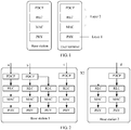
- FIG. 3 is a schematic flowchart of transmitting downlink service data and control information in a protocol layer structure in the prior art.
- Downlink service data (including first downlink service data and second downlink service data) in a base station is split in a PDCP layer of a second carrier to a first carrier.
- the first downlink service data is sent to the user terminal by using an RLC layer, a MAC layer, and a PHY layer of the first carrier.
- the second downlink service data is sent to the user terminal by using an RLC layer, a MAC layer, and a PHY layer of the second carrier.
- the RLC layer, the MAC layer, and the PHY layer of the first carrier in the user terminal all generate corresponding control information, and the control information is sent to the base station by using the first carrier.
- control information needs to be transmitted on both the first carrier and the second carrier in the communications system, resulting in relatively high air interface overheads and reduced transmission performance of the communications system.
- embodiments of the present invention provide a method and an apparatus for transmitting control information.
- Control information that needs to be sent by using a plurality of different carriers is sent by using one of the carriers, thereby reducing air interface overheads of a communications system and improving transmission performance of the communications system.
- control information corresponding to the carrier may be sent by using another carrier, so that load of this carrier is reduced.
- the technology described in this embodiment of the present invention may be used in various communications systems, for example, an LTE communications system, a fifth-generation mobile communication technology (the 5th Generation Mobile Communication Technology, 5G) communications system, a communications system in which a plurality of radio access technologies (Radio Access Technology, RAT) coexist or another similar communications system.
- LTE Long Term Evolution
- 5G Fifth Generation Mobile Communication Technology
- RAT Radio Access Technology
- the method for transmitting control information provided in this embodiment of the present invention is applicable to a multi-connectivity technology for implementing an ideal backhaul (ideal backhaul) connection between different base stations, where the multi-connectivity technology for implementing an ideal backhaul connection between different base stations includes a DC technology for implementing an ideal backhaul connection between different base stations.
- the DC technology for implementing an ideal backhaul (ideal backhaul) connection between different base stations is only an explanation for convenience of understanding this embodiment of the present invention. During actual use, such a technology may have another name. This is not specifically limited in this embodiment of the present invention.
- FIG. 4 is a schematic structural diagram of a communications system according to an embodiment of the present invention.
- the communications system includes a user terminal 100 and one or more base stations 101 connected to the user terminal 100.
- the user terminal 100 and the base station 101 are connected by using a network.
- a first communications device in this embodiment of the present invention may be the user terminal 100, or may be a base station apparatus that includes at least one the base station 101.
- the user terminal 100 includes a first functional entity and a second functional entity, a first carrier is configured for the first functional entity, and a second carrier is configured for the second functional entity.
- the first functional entity of the user terminal 100 is an RLC entity for which a first carrier is configured, or is a MAC entity for which a first carrier is configured, or is a PHY entity for which a first carrier is configured.
- the second functional entity of the user terminal 100 is an RLC entity for which a second carrier is configured, or is a MAC entity for which a second carrier is configured, or is a PHY entity for which a second carrier is configured.
- the second functional entity of the user terminal 100 After obtaining first control information of the first functional entity of the user terminal 100, the second functional entity of the user terminal 100 sends, by using the second carrier, the first control information to the base station 101 that communicates with the user terminal 100.
- the first control information includes a first identifier indicating the first carrier.
- the second functional entity of the user terminal 100 can recognize the first control information based on the first identifier.
- the base station 101 can determine a target functional entity of the first control information based on the first identifier included in the first control information.
- the first identifier may be a logic channel identification (Logical Channel Identification, LCH ID) of the first carrier, or may be a name of the first carrier, or may be other information used to represent the first carrier, and more examples are not listed herein.
- LCH ID Logical Channel Identification
- the second functional entity of the user terminal 100 may further obtain second control information of the second functional entity, and send, by using the second carrier, the second control information to the base station 101 that communicates with the user terminal 100.
- the second functional entity of the user terminal 100 may further receive third control information that is sent by the base station 101 and that includes the first identifier, and send the third control information to the first functional entity of the user terminal 100 based on the first identifier.
- the second functional entity of the user terminal 100 may further determine, based on the first identifier, the target functional entity of the first control information.
- the base station apparatus further includes the first functional entity and the second functional entity, the first carrier is configured for the first functional entity, and the second carrier is configured for the second functional entity.
- the first functional entity of the base station apparatus is an RLC entity for which a first carrier is configured, or is a MAC entity for which a first carrier is configured, or is a PHY entity for which a first carrier is configured.
- the second functional entity of the base station apparatus is an RLC entity for which a second carrier is configured, or is a MAC entity for which a second carrier is configured, or is a PHY entity for which a second carrier is configured.
- Functions completed by the first functional entity of the base station apparatus are similar to those completed by the first functional entity of the user terminal 100.
- Functions completed by the second functional entity of the base station apparatus are similar to those completed by the second functional entity of the user terminal 100.
- the functions are not described in detail herein.
- the first functional entity of the base station apparatus and the second functional entity of the base station apparatus may belong to a same base station 101 or may belong to different base stations 101.
- the user terminal used in this embodiment of the present invention is a wireless terminal.
- the wireless terminal may be a device that provides a user with speech and/or data connectivity, a handheld device having a wireless connection function, or another processing device connected to a wireless modem.
- the wireless terminal may communicate with one or more core networks by using a radio access network (Radio Access Network, RAN).
- Radio Access Network RAN
- the wireless terminal may be a mobile terminal, for example, a mobile phone (or referred to as a "cellular" phone) or a computer having a mobile terminal, or may be a portable mobile apparatus, a pocket-sized mobile apparatus, a handheld mobile apparatus, a computer built-in mobile apparatus or an in-vehicle mobile apparatus which exchanges speech and/or data with a radio access network, for example, a device such as a personal communication service (Personal Communication Service, PCS) phone, a cordless phone, a Session Initiate Protocol (SIP) phone, a wireless local loop (Wireless Local Loop, WLL) station, or a personal digital assistant (Personal Digital Assistant, PDA).
- PCS Personal Communication Service
- SIP Session Initiate Protocol
- WLL Wireless Local Loop
- PDA Personal Digital Assistant
- the wireless terminal may also be referred to as a system, a subscriber unit (Subscriber Unit), a subscriber station (Subscriber Station), a mobile station (Mobile Station), a mobile (Mobile), a remote station (Remote Station), an access point (Access Point), a remote terminal (Remote Terminal), an access terminal (Access Terminal), a user agent (User Agent), a user device (User Device), or user equipment (User Equipment).
- the user terminal includes the first functional entity and the second functional entity
- the first carrier is configured for the first functional entity of the user terminal
- the second carrier is configured for the second functional entity of the user terminal
- the base station apparatus also includes the first functional entity and the second functional entity
- the first carrier is also configured for the first functional entity of the base station apparatus
- the second carrier is also configured for the second functional entity of the base station apparatus
- communication is completed between the user terminal and the base station apparatus
- the base station apparatus sends first downlink service data to the user terminal by using the first carrier
- the user terminal sends control information to the base station apparatus.
- the user terminal in this embodiment of the present invention is the first communications device
- the base station apparatus is a second communications device.
- a method for transmitting control information includes the following steps.
- a second functional entity of a user terminal obtains first control information of a first functional entity of the user terminal, where the first control information includes a first identifier.
- the first identifier is used to indicate a first carrier.
- the second functional entity of the user terminal sends the first control information to a second functional entity of a base station apparatus by using a second carrier.
- S503 The second functional entity of the base station apparatus obtains the first control information by using the second carrier.
- the second functional entity of the base station apparatus sends the first control information to the first functional entity of the base station apparatus based on the first identifier included in the first control information.
- a method for obtaining the first control information by the second functional entity of the user terminal may be: receiving, by the second functional entity of the user terminal, first information sent by the first functional entity of the user terminal, and adding the first identifier used to indicate the first carrier to the received first information.
- the first information is feedback information or is status information or is the feedback information and the status information.
- the feedback information is information that corresponds to first downlink service data and that is generated by the first functional entity of the user terminal after the first functional entity of the user terminal receives, by using the first carrier, the first downlink service data sent by a base station.
- the status information is information generated by the first functional entity of the user terminal based on a preset mechanism.
- the first functional entity of the user terminal is an RLC entity and the base station apparatus uses an RLC AM (Acknowledged Mode) mode to send the first downlink service data to the user terminal
- RLC AM Acknowledged Mode
- the RLC entity after receiving, by using the first carrier, the first downlink service data sent by the base station, the RLC entity generates feedback information corresponding to the first downlink service data.
- the feedback information is an RLC PDU (RLC PDU).
- the RLC PDU is used to feed back a sequence number corresponding to the RLC PDU that is received by the RLC entity correctly or not.
- the preset mechanism in this embodiment of the present invention is determined based on actual application and a protocol that is satisfied by the first functional entity of the user terminal. This is not specifically limited in this embodiment of the present invention.
- the MAC entity when the MAC entity finds that high layer data needs to be sent, the MAC entity generates status information.
- the status information is a buffer status report (Buffer Status Report, BSR).
- BSR Buffer Status Report
- the BSR is used to feed back how much data needs to be sent by the user terminal on a carrier configured for the MAC entity.
- the first information in this embodiment of the present invention is one data packet.
- the data packet is named the first information only for convenience of understanding and description.
- the name of the first information is different based on a variation of the first functional entity. This is not specifically limited in this embodiment of the present invention.
- the first identifier may be an LCH ID of the first carrier, or may be a name of the first carrier, or may be other information used to represent the first carrier, and descriptions are not provided herein by using examples one by one in this embodiment of the present invention.
- the first identifier added by the second functional entity of the user terminal to the first information may be placed in a packet header of the first information, or may be placed in a payload of the first information. This is not specifically limited in this embodiment of the present invention.
- a method for obtaining the first control information by the second functional entity of the user terminal may be: receiving, by the second functional entity of the user terminal, the first control information sent by the first functional entity of the user terminal.
- the first control information includes the first identifier used to indicate the first carrier and the first information.
- the definition of the first information is the same as the foregoing definition of the first information. Details are not described herein again.
- the first information is generated by the first functional entity of the user terminal. Therefore, the first control information sent by the first functional entity of the user terminal is the first identifier added to the first information generated by the first functional entity of the user terminal after the first functional entity generates the first information. The first functional entity of the user terminal then sends the first control information including the first identifier and the first information to the second functional entity of the user terminal.
- the first identifier added by the first functional entity of the user terminal to the first information is the same as the first identifier added by the second functional entity of the user terminal to the first information. Details are not described herein again.
- the first identifier added by the first functional entity of the user terminal to the first information may be placed in a packet header of the first information or may be placed in a payload of the first information. This is not specifically limited in this embodiment of the present invention.
- the second functional entity of the user terminal in this embodiment of the present invention may further obtain second control information of the second functional entity of the user terminal.
- the second control information may be second information that corresponds to second service data and that is generated by the second functional entity of the user terminal after the second functional entity of the user terminal receives, by using the second carrier, the second service data sent by the base station.
- the second control information may alternatively be the second information generated by the second functional entity based on the preset mechanism.
- the second control information may further include the second information and a second identifier that is used to indicate the second carrier.
- the first control information already includes the first identifier used to indicate the first carrier. Therefore, regardless of whether the second control information includes the second identifier used to indicate the second carrier, the second functional entity of the user terminal may distinguish between the first control information and the second control information based on the first identifier.
- the second functional entity of the user terminal may obtain the second control information before obtaining the first control information, or may obtain the second control information after obtaining the first control information, or may obtain the first control information and the second control information at the same time. This is not specifically limited in this embodiment of the present invention.
- the first functional entity of the user terminal is an RLC entity in this embodiment of the present invention
- the first information in this embodiment of the present invention includes an RLC PDU and the second functional entity of the user terminal is an RLC entity or a MAC entity.
- Any RLC entity in the foregoing performs data processing based on an existing RLC protocol.
- the foregoing MAC entity performs data processing based on an existing MAC protocol.
- the first functional entity of the user terminal is an RLC entity and the second functional entity of the user terminal is an RLC entity
- the first functional entity of the user terminal sends the RLC PDU generated by the first functional entity to the second functional entity of the user terminal.
- the first functional entity of the user terminal may send the RLC PDU generated by the first functional entity to the second functional entity of the user terminal.
- an existing MAC functional entity is responsible for scheduling data of an RLC functional entity. Therefore, if the first functional entity of the user terminal is an RLC entity and the second functional entity of the user terminal is a MAC entity in this embodiment of the present invention, the MAC entity may schedule control information from the first functional entity of the user terminal. After generating the RLC PDU, the first functional entity of the user terminal sends the RLC PDU generated by the first functional entity to the second functional entity of the user terminal.
- the first information includes a MAC PDU and the second functional entity of the user terminal is a MAC entity.
- the first information includes PHY control information and the second functional entity of the user terminal is a PHY entity.
- the RLC entity is a term of a third Generation Partnership Project (3rd Generation Partnership Project, 3GPP) network, and a functional entity having a similar function may exist in another non-3GPP network but is not named an RLC entity.
- a logic link control (Logical Link Control, LLC) layer in a Wireless-Fidelity (Wireless-Fidelity, Wi-Fi) system has a function similar to that of an RLC entity in a 3GPP network. Therefore, the RLC entity in this embodiment of the present invention is used to represent a functional entity having a similar function.
- the MAC entity in this embodiment of the present invention is used to represent a functional entity having a function similar to that of a MAC functional entity in a 3GPP network
- the PHY entity is used to represent a functional entity having a function similar to a PHY functional entity in a 3GPP network.
- the second functional entity of the user terminal After obtaining the first control information, the second functional entity of the user terminal adds the obtained first control information to the second carrier, and sends the first control information to the base station apparatus.
- the second functional entity of the user terminal sends the first control information to the base station apparatus by using the second carrier, that is, performs S502.
- the second functional entity of the user terminal after obtaining the second control information, also adds the second control information to the second carrier, and sends the second control information to the base station.
- an order of sending the first control information and the second control information by the second functional entity of the user terminal is not limited in this embodiment of the present invention. If the second functional entity of the user terminal obtains the first control information first, the second functional entity of the user terminal sends the first control information first. If the second functional entity of the user terminal obtains the second control information first, the second functional entity of the user terminal sends the second control information first. If the second functional entity of the user terminal obtains the first control information and the second control information at the same time, the second functional entity of the user terminal sends the first control information and the second control information at the same time.
- the PHY entity sends the first PHY control information and the second PHY control information to the base station apparatus at the same time by using the second carrier.
- the PHY entity when the PHY entity sends the first PHY control information and the second PHY control information to the base station at the same time by using the second carrier, the PHY entity first encodes the first PHY control information and the second PHY control information based on a preset encoding manner and then sends the encoded information.
- the PHY entity encodes the first PHY control information and the second PHY control information based on a preset bit sequence.
- the PHY entity then sends the first PHY control information and the second PHY control information at the same time in a transmit time interval (Transmission Time Interval, TTI) /some TTIs of the second carrier.
- TTI Transmission Time Interval
- the first control information is no longer sent by using the first carrier, so that load of the first carrier is reduced, and overheads of the first carrier are reduced.
- the first control information and the second control information are both sent by using the second carrier. In this way, air interface overheads of a communications system are reduced, and transmission performance of the communications system is improved.
- the communications system may include at least two carriers.
- the first carrier and the second carrier are any two carriers in the communications system.
- air interface overheads of the communications system can be reduced and transmission performance of the communications system can be improved.
- the first carrier carries a tiny amount of uplink service data (or does not carry uplink service data) and carries a large amount of first downlink service data in this embodiment of the present invention
- the first control information corresponding to the first carrier is sent by using the second carrier. In this way, overheads of the first carrier can be reduced and load of the first carrier can be reduced.
- the second carrier is configured for the second functional entity of the base station apparatus in this embodiment of the present invention. Therefore, the second functional entity of the base station apparatus obtains the first control information by using the second carrier, that is, performs S503.
- the base station apparatus can learn, based on the first identifier included in the first control information, that a target functional entity of the first control information is the first functional entity of the base station apparatus. Therefore, the second functional entity of the base station apparatus sends the first control information to the first functional entity of the base station apparatus based on the first identifier, that is, performs S504.
- the first control information in this embodiment of the present invention is transmitted by using the second carrier, so that load of the first carrier is reduced and overheads of the first carrier are reduced.
- the method for transmitting control information provided in this embodiment of the present invention may be applicable to any functional entity in the user terminal and the base station apparatus, and may be applicable to all functional entities in the user terminal and the base station apparatus.
- the first carrier and the second carrier in this embodiment of the present invention may belong to a same RAT technology or may belong to different RAT technologies.
- the base station apparatus in this embodiment of the present invention includes at least one base station.
- the first functional entity of the base station apparatus and the second functional entity of the base station apparatus may belong to a same base station or may belong to different base stations.
- the base station apparatus is only an explanation for convenience of description and understanding in this embodiment of the present invention. During actual use, an apparatus that includes at least one base station may have another name. This is not specifically limited in this embodiment of the present invention.
- An application scenario in which the first functional entity of the base station apparatus and the second functional entity of the base station apparatus belong to different base stations may be a coordinated multipoint transmission (Coordinated Multiple Points Transmission/Reception, CoMP) scenario or may be a scenario of a base station network (for example, a network of macro base stations and micro base stations).
- CoMP Coordinated Multiple Points Transmission/Reception
- the second functional entity of the user terminal before the second functional entity of the user terminal obtains the first control information of the first functional entity of the user terminal, the second functional entity of the user terminal in the method for transmitting control information provided in this embodiment of the present invention further obtains a control information transmission rule used to instruct the second functional entity of the user terminal to send the first control information by using the second carrier.
- the method for transmitting control information provided in this embodiment of the present invention further includes the following steps.
- S600 The second functional entity of the user terminal obtains the control information transmission rule.
- the control information transmission rule is used to instruct the second functional entity of the user terminal to send the first control information by using the second carrier.
- a method for obtaining the control information transmission rule by the second functional entity of the user terminal is: obtaining, by the second functional entity of the user terminal, the control information transmission rule sent by the base station apparatus, where the control information transmission rule is determined by the base station apparatus when the base station apparatus determines that an attribute value of the first carrier and an attribute value of the second carrier both satisfy a preset condition.
- the base station apparatus may send the control information transmission rule to the user terminal by using a Radio Resource Control (Radio Resource Control, RRC) message, MAC information or PHY control information.
- RRC Radio Resource Control
- the preset condition in this embodiment of the present invention may be any one of the following conditions:
- the user terminal sends the first control information by using the second carrier, so that a signal-to-noise ratio of the transmitted first control information can be improved, the reliability of the first control information is ensured and a utilization ratio of a carrier resource is improved at the same time.
- the base station apparatus determines the control information transmission rule based on attribute values of different carriers during actual application.
- the base station apparatus in this embodiment of the present invention includes only one base station, the first functional entity of the base station apparatus and the second functional entity of the base station apparatus belong to a same base station.
- the method for transmitting control information provided in this embodiment of the present invention is used in this scenario, and a procedure of transmitting downlink service data, first control information, and second control information in a protocol layer structure of the user terminal and the base station is shown in FIG. 7 .
- Each protocol layer in the user terminal and the base station may be regarded as residing in a functional entity that can be separated from another protocol layer.
- Downlink service data sent by the base station is split in a PDCP layer of the second carrier to the first carrier.
- the first downlink service data is sent to the user terminal by using an RLC layer, a MAC layer, and a PHY layer of the first carrier.
- the second downlink service data is sent to the user terminal by using an RLC layer, a MAC layer, and a PHY layer of the second carrier.
- the RLC layer of the second carrier in the user terminal obtains the first control information corresponding to the RLC layer of the first carrier, and sends, by using the second carrier, the first control information obtained by the RLC layer.
- the MAC layer of the second carrier and the PHY layer of the second carrier in the user terminal obtain the corresponding first control information, and send the obtained first control information by using the second carrier.
- the RLC layer, the MAC layer, and the PHY layer of the second carrier of the user terminal all generate corresponding second control information, and the respective generated second control information is sent by using the second carrier.
- the PHY layer of the second carrier in the base station receives the first control information by using the second carrier, and sends the first control information received by the PHY layer to the PHY layer of the first carrier in the base station.
- the MAC layer of the second carrier in the base station receives the corresponding first control information by using the second carrier, and sends the first control information received by the MAC layer to the MAC layer of the first carrier in the base station.
- the RLC layer of the second carrier in the base station receives the corresponding first control information by using the second carrier, and sends the first control information received by the RLC layer to the RLC layer of the first carrier in the base station.
- the first control information and the second control information between the base station and the user terminal are both sent by using the second carrier, so that air interface overheads of a communications system are reduced and transmission performance of the communications system is improved. Further, the first carrier no longer transmits control information, and the load of the first carrier is reduced.
- control information is similar to that in the foregoing description. Details are not described herein again.
- the transmission method provided in this embodiment of the present invention is further applicable to a scenario in which the first carrier and the second carrier belong to different RAT technologies and the first carrier and the second carrier perform carrier aggregation.
- the PDCP, the RLC, and the MAC are shared between different carriers. Therefore, this embodiment of the present invention is applicable to a PHY entity in the carrier aggregation technology.
- a method for processing control information by the PHY entity in the carrier aggregation technology is the same as the method for processing control information in the foregoing PHY entity. Details are not described herein again.
- the PHY entity in the carrier aggregation technology uses the transmission method provided in this embodiment of the present invention to send the CSI of the first carrier by using the second carrier, so that a feedback cycle of CSI of the first carrier can be shortened and scheduling performance during transmission of service data by using the first carrier can be improved.
- the first carrier is configured for the first functional entity in the first communications device (which may be the user terminal or may be the base station apparatus), the second carrier is configured for the second functional entity.
- the second functional entity After obtaining the first control information of the first functional entity, the second functional entity sends the first control information by using the second carrier.
- the first control information is no longer sent by using the first carrier, and control information sent by a communications device occupies only resources of the second carrier, thereby reducing air interface overheads of a communications system and improving transmission performance of the communications system.
- control information corresponding to the carrier may be sent by using another carrier, so that overheads of the carrier can be reduced and load of the carrier can be reduced.
- An embodiment of the present invention provides a communications device 1.
- the communications device 1 in this embodiment of the present invention is a first communications device.
- the communications device 1 may be a user terminal or may be a base station apparatus that includes at least one base station.
- the communications device 1 is configured to perform steps performed by the user terminal or the base station apparatus in the foregoing method.
- the communications device 1 may include modules corresponding to corresponding steps.
- the communications device 1 includes a first functional entity 80 and a second functional entity 81.
- a first carrier is configured for the first functional entity 80
- a second carrier is configured for the second functional entity 81.
- the first functional entity 80 and the second functional entity 81 are specifically implemented by using a corresponding software program and/or application module.
- the first functional entity 80 includes a generation module 80a and a second sending module 80b
- the second functional entity 81 includes an obtaining module 81a, a first sending module 81b, and a processing module 81c.
- the obtaining module 81a is configured to obtain first control information of the first functional entity, where the first control information includes a first identifier, and the first identifier is used to indicate the first carrier.
- the first sending module 81b is configured to send, by using the second carrier, the first control information obtained by the obtaining module 81a to another communications device.
- the another communications device is a device that communicates with the communications device provided in this embodiment of the present invention.
- the first carrier and the second carrier are also configured for the another communications device.
- the generation module 80a is configured to generate first information, where the first information is feedback information or is status information or is the feedback information and the status information, the feedback information is information that corresponds to first service data and that is generated after the first service data is received by using the first carrier, and the status information is information generated based on a preset mechanism.
- the second sending module 80b is configured to send the first information generated by the generation module 80a to the second functional entity 81.
- the obtaining module 81a is specifically configured to receive the first information sent by the second sending module 80b of the first functional entity 80.
- processing module 81c is configured to add the first identifier to the first information received by the obtaining module 81a, to generate the first control information.
- the generation module 80a is further configured to generate the first control information, where the first control information includes the first identifier and the first information, the first information is feedback information or is status information or is the feedback information and the status information, the feedback information is information that corresponds to first service data and that is generated by the first functional entity after the first functional entity receives the first service data by using the first carrier, and the status information is information generated by the first functional entity based on a preset mechanism.
- the second sending module 80b is configured to send the first control information generated by the generation module 80a to the second functional entity 81.
- the obtaining module 81a is further specifically configured to receive the first control information sent by the second sending module 80b of the first functional entity 80.
- the obtaining module 81a is further configured to: before obtaining the first control information, obtain a control information transmission rule, where the control information transmission rule is used to instruct the first sending module 81b to send the first control information by using the second carrier.
- the base station apparatus further includes a third functional entity 82.
- the third functional entity 82 includes a determining module 82a and a third sending module 82b.
- the determining module 82a is configured to: when determining that an attribute value of the first carrier and an attribute value of the second carrier both satisfy a preset condition, determine the control information transmission rule.
- the third sending module 82b is configured to send the control information transmission rule determined by the determining module 82a to the second functional entity 81.
- the obtaining module 81a of the second functional entity 81 is specifically configured to receive the control information transmission rule sent by the third sending module 82b of the third functional entity 82.
- the communications device 1 is a user terminal
- the user terminal communicates with a base station apparatus
- the first carrier and the second carrier are configured for the base station apparatus
- the obtaining module 81 a of the second functional entity 81 is specifically configured to receive the control information transmission rule sent by the base station apparatus, where the control information transmission rule is determined by the base station apparatus when the base station apparatus determines that an attribute value of the first carrier and an attribute value of the second carrier both satisfy a preset condition.
- the preset condition includes at least one of a first condition, a second condition, and a third condition;
- the first condition is that a TTI of the first carrier is greater than a first preset threshold, a TTI of the second carrier is less than or equal to a second preset threshold, and the first preset threshold is greater than or equal to the second preset threshold;
- the second condition is that signal quality of the first carrier is less than a third preset threshold, signal quality of the second carrier is greater than a fourth preset threshold, and the fourth preset threshold is greater than the third preset threshold;
- the third condition is that load of the first carrier is greater than a fifth preset threshold, load of the second carrier is less than a sixth preset threshold, and the fifth preset threshold is greater than the sixth preset threshold.
- the obtaining module 81a of the second functional entity 81 is further configured to receive, by using the second carrier, third control information sent by the another communications device, where the third control information includes the first identifier.
- the first sending module 81b of the second functional entity 81 is further configured to send the third control information to the first functional entity 80 based on the first identifier included in the third control information received by the obtaining module 81a.
- the communications device 1 is a receive end device of control information.
- the communications device 1 can learn, based on the first identifier included in the third control information, that a target functional entity of the third control information is the first functional entity 80 for which the first carrier is configured. Therefore, the first sending module 81b sends the third control information to the first functional entity 80.
- the communications device 1 is the base station apparatus.
- the communications device 1 provided in this embodiment of the present invention may be a transmit end device of control information or may be a receive end device of control information.
- the communications device 1 is a transmit end device of control information
- the first functional entity is a RLC entity
- the first information includes an RLC PDU
- the second functional entity is an RLC entity or a media access control MAC entity
- the first functional entity is a MAC entity
- the first information includes a MAC PDU
- the second functional entity is a MAC entity
- the first functional entity is a PHY entity
- the first information includes PHY control information
- the second functional entity is a PHY entity.
- the communications device 1 is a receive end device of control information
- the first functional entity is a RLC entity
- the first information includes an RLC PDU
- the second functional entity is an RLC entity
- the first functional entity is a MAC entity
- the first information includes a MAC PDU
- the second functional entity is a MAC entity
- the first functional entity is a PHY entity
- the first information includes PHY control information
- the second functional entity is a PHY entity.
- the foregoing RLC entities all perform data processing based on the existing RLC protocol
- the foregoing MAC entities all perform data processing based on the existing MAC protocol
- the foregoing PHY entities all perform data processing based on the existing PHY protocol.
- the communications device 1 in this embodiment is only logic division based on functions implemented by the communications device 1. During actual application, in the communications device 1, the foregoing units may be combined or divided. In addition, the functions implemented by the communications device 1 provided in this embodiment correspond one-to-one to those implemented by the user terminal or the base station apparatus in the method for transmitting control information provided in the foregoing embodiments. A more detailed processing procedure implemented by the communications device 1 has been described in detail in the foregoing method embodiment. Details are not described herein again.
- the communications device includes an interface circuit 100, a processor 101, a memory 102, and a system bus 103.
- the interface circuit 100, the processor 101, and the memory 102 are connected to each other and complete communication with each other by using the system bus 103.
- the structure of the communications device in FIG. 10 does not constitute a limitation to the communications device, and may include more or fewer components than those shown in the figures, or a combination of some components, or different component layouts.
- the communications device when the communications device is running, the communications device performs the method for transmitting control information described in the foregoing embodiment.
- the communications device performs the method for transmitting control information described in the foregoing embodiment.
- a specific method for transmitting control information refer to related description in the foregoing embodiment shown in FIG. 5 or FIG. 6 . Details are not described herein again.
- the interface circuit 100 is configured to implement a communication connection between the communications device and another communications device.
- the memory 102 may be configured to store a software program and an application program.
- the memory 102 may mainly include a program storage area and a data storage area.
- the program storage area may store an operating system, an application program required by at least one function (for example, generating first control information and second control information), and the like.
- the data storage area may store the first control information.
- the memory 102 may include a volatile memory, for example, a high-speed random-access memory (Random-access Memory, RAM), or the memory 102 may include a non-volatile memory, for example, at least one magnetic disk storage device, a flash memory device, or another volatile solid-state storage device.
- RAM Random-access Memory
- non-volatile memory for example, at least one magnetic disk storage device, a flash memory device, or another volatile solid-state storage device.
- the processor 101 runs the software program and the application module stored in the memory 102 to perform various functional applications and data processing of the communications device.
- the processor 101 is a control center of the communications device, connected to various parts of the entire communications device by using various interfaces and lines, performs various functions of the communications device and processes data by running or executing the software program and/or the application module stored in the memory 102 and invoking data stored in the memory 102, to perform overall monitoring on the communications device.
- the processor 101 runs the software program and/or the application module stored in the memory 102.
- the software program and/or the application module may implement functions of a first functional entity 80 and a second functional entity 81.
- the first functional entity 80 is configured to: generate first information or generate the first control information, and send the first information or the first control information generated by the first functional entity 80 to the second functional entity 81.
- the second functional entity 81 is configured to: receive the first information sent by the first functional entity 80, and add a first identifier to the first information to generate the first control information, or, is configured to receive the first control information sent by the first functional entity 80, and is configured to send the first control information.
- the processor 101 may be a central processing unit (Central Processing Unit, CPU).
- the processor 101 may alternatively be another general-purpose processor, a digital signal processor (Digital Signal Processing, DSP) or another programmable logic device or transistor logic device, a discrete hardware component, or the like.
- the general-purpose processor may be a microprocessor or the processor may be any conventional processor or the like.
- the system bus 103 may include a data bus, a power bus, a control bus, a signal status bus, and the like. In this embodiment, for a purpose of clear description, all buses are marked as the system bus 103 in FIG. 10 .
- This embodiment of the present invention provides a communications device.
- the communications device includes the first functional entity and the second functional entity, a first carrier is configured for the first functional entity, and a second carrier is configured for the second functional entity.
- the second functional entity After obtaining the first control information of the first functional entity, the second functional entity sends the first control information by using the second carrier.
- the first control information is no longer sent by using the first carrier, and control information sent by the communications device occupies only resources of the second carrier, thereby reducing air interface overheads of a communications system and improving transmission performance of the communications system.
- control information corresponding to the carrier may be sent by using another carrier, so that overheads of the carrier can be reduced and load of the carrier can be reduced.
- the disclosed system, mobile device, and method may be implemented in other manners.
- the described mobile device embodiment is merely an example.
- the module or unit division is merely logical function division and may be other division in actual implementation.
- a plurality of units or components may be combined or integrated into another system, or some features may be ignored or not performed.
- the displayed or discussed mutual couplings or direct couplings or communication connections may be implemented through some interfaces.
- the indirect couplings or communication connections between the mobile devices or units may be implemented in electronic, mechanical, or other forms.
- the units described as separate parts may or may not be physically separate, and parts displayed as units may or may not be physical units, may be located in one position, or may be distributed on a plurality of network units. Some or all of the units may be selected based on actual needs to achieve the objectives of the solutions of the embodiments.
- functional units in the embodiments of the present invention may be integrated into one processing unit, or each of the units may exist alone physically, or two or more units are integrated into one unit.
- the integrated unit may be implemented in a form of hardware, or may be implemented in a form of a software functional unit.
- the integrated unit When the integrated unit is implemented in the form of a software functional unit and sold or used as an independent product, the integrated unit may be stored in a computer-readable storage medium. Based on such an understanding, the technical solutions of the present invention essentially, or the part contributing to the prior art, or all or a part of the technical solutions may be implemented in the form of a software product.
- the software product is stored in a storage medium and includes several instructions for instructing a computer device (which may be a personal computer, a server, or a network device) or a processor (processor) to perform all or a part of the steps of the methods described in the embodiments of the present invention.
- the foregoing storage medium includes: any medium that can store program code, such as a USB flash drive, a removable hard disk, a read-only memory (ROM, Read-Only Memory), a random-access memory (RAM, Random-access Memory), a magnetic disk, or an optical disc.
- program code such as a USB flash drive, a removable hard disk, a read-only memory (ROM, Read-Only Memory), a random-access memory (RAM, Random-access Memory), a magnetic disk, or an optical disc.
Claims (5)
- Procédé de transmission d'informations de commande, dans lequel le procédé de transmission est mis en œuvre par un premier dispositif de communication, le premier dispositif de communication comprend une première entité fonctionnelle (80) et une deuxième entité fonctionnelle (81), une première porteuse est configurée pour la première entité fonctionnelle (80), une seconde porteuse est configurée pour la deuxième entité fonctionnelle (81) et le procédé de transmission comprend :l'obtention (S501), par la deuxième entité fonctionnelle (81), des premières informations de commande de la première entité fonctionnelle (80), les premières informations de commande comprenant un premier identifiant, et le premier identifiant étant utilisé pour indiquer la première porteuse ; etl'envoi (S502), par la deuxième entité fonctionnelle (81), des premières informations de commande à un second dispositif de communication à l'aide de la seconde porteuse ;dans lequel l'obtention (S501), par la deuxième entité fonctionnelle (81), des premières informations de commande de la première entité fonctionnelle (80) comprend :la réception, par la deuxième entité fonctionnelle (81), des premières informations envoyées par la première entité fonctionnelle (80), les premières informations étant des informations de rétroaction ou des informations d'état ou étant les informations de rétroaction et les informations d'état, les informations de rétroaction étant des informations qui correspondent aux premières données de service et qui sont générées par la première entité fonctionnelle (80) après que la première entité fonctionnelle (80) a reçu les premières données de service à l'aide la première porteuse, et les informations d'état étant des informations générées par la première entité fonctionnelle (80) sur la base d'un mécanisme prédéfini ; etl'ajout, par la deuxième entité fonctionnelle (81), du premier identifiant aux premières informations pour générer les premières informations de commande ;dans lequel avant l'obtention (S501), par la deuxième entité fonctionnelle (81), des premières informations de commande de la première entité fonctionnelle (80), le procédé de transmission comprend en outre :l'obtention (S600), par la deuxième entité fonctionnelle (81), d'une règle de transmission d'informations de commande, la règle de transmission d'informations de commande étant utilisée pour donner l'instruction à la deuxième entité fonctionnelle (81) d'envoyer les premières informations de commande à l'aide de la seconde porteuse ;dans lequel le premier dispositif de communication est un appareil de station de base, et l'appareil de station de base comprend en outre une troisième entité fonctionnelle (81) ; etl'obtention (S501), par la deuxième entité fonctionnelle (81), d'une règle de transmission d'informations de commande comprenant spécifiquement :
la réception, par la deuxième entité fonctionnelle (81), de la règle de transmission d'informations de commande envoyée par la troisième entité fonctionnelle (81), la règle de transmission d'informations de commande étant déterminée par la troisième entité fonctionnelle (81) lorsque la troisième entité fonctionnelle (81) détermine qu'une valeur d'attribut de la première porteuse et une valeur d'attribut de la seconde porteuse remplissent toutes deux une condition prédéfinie. - Procédé de transmission selon la revendication 1, dans lequel la condition prédéfinie comprend une première condition et/ou une deuxième condition et/ou une troisième condition ;
la première condition est qu'un intervalle de temps de transmission, TTI, de la première porteuse est supérieur à un premier seuil prédéfini, un TTI de la seconde porteuse est inférieur ou égal à un deuxième seuil prédéfini et le premier seuil prédéfini est supérieur ou égal au deuxième seuil prédéfini ;
la deuxième condition est que la qualité du signal de la première porteuse est inférieure à un troisième seuil prédéfini, la qualité du signal de la seconde porteuse est supérieure à un quatrième seuil prédéfini et le quatrième seuil prédéfini est supérieur au troisième seuil prédéfini ; et
la troisième condition est que la charge de la première porteuse est supérieure à un cinquième seuil prédéfini, la charge de la seconde porteuse est inférieure à un sixième seuil prédéfini et le cinquième seuil prédéfini est supérieur au sixième seuil prédéfini. - Procédé de transmission selon l'une quelconque des revendications 1 à 2, dans lequel le procédé de transmission comprend en outre :la réception, par la deuxième entité fonctionnelle (81) à l'aide de la seconde porteuse, des troisièmes informations de commande envoyées par le second dispositif de communication, les troisièmes informations de commande comprenant le premier identifiant ; etl'envoi, par la deuxième entité fonctionnelle (81), des troisièmes informations de commande à la première entité fonctionnelle (80) sur la base du premier identifiant.
- Dispositif de communication (1), le dispositif de communication (1) comprenant une première entité fonctionnelle (80) et une deuxième entité fonctionnelle (81), une première porteuse étant configurée pour la première entité fonctionnelle (80) et une seconde porteuse étant configurée pour la deuxième entité fonctionnelle (81) ;
la deuxième entité fonctionnelle (81) comprend un module d'obtention (81a) et un premier module d'envoi (81b) ;
le module d'obtention (81a) est configuré pour obtenir des premières informations de commande de la première entité fonctionnelle (80), les premières informations de commande comprenant un premier identifiant, et le premier identifiant étant utilisé pour indiquer la première porteuse ; et
le premier module d'envoi (81b) est configuré pour envoyer, à l'aide de la seconde porteuse, les premières informations de commande obtenues par le module d'obtention (81a) à un autre dispositif de communication ;
dans lequel la première entité fonctionnelle (80) comprend un module de génération (80a) et un deuxième module d'envoi (80b) ;
le module de génération (80a) est configuré pour générer des premières informations, les premières informations étant des informations de rétroaction ou des informations d'état ou étant les informations de rétroaction et les informations d'état, les informations de rétroaction étant des informations qui correspondent aux premières données de service et qui sont générées après que les premières données de service sont reçues à l'aide de la première porteuse, et les informations d'état sont des informations générées sur la base d'un mécanisme prédéfini ;
le deuxième module d'envoi (80b) est configuré pour envoyer les premières informations générées par le module de génération (80a) à la deuxième entité fonctionnelle (81) ;
le module d'obtention est spécifiquement configuré pour recevoir les premières informations envoyées par le deuxième module d'envoi de la première entité fonctionnelle (80) ;
la deuxième entité fonctionnelle (81) comprend en outre un module de traitement (81c), et le module de traitement (81c) est configuré pour ajouter le premier identifiant aux premières informations reçues par le module d'obtention (81a), pour générer les premières informations de commande ;
dans lequel le module d'obtention (81a) est en outre configuré pour :avant d'obtenir les premières informations de commande, obtenir une règle de transmission d'informations de commande, la règle de transmission d'informations de commande étant utilisée pour donner l'instruction au premier module d'envoi (81b) de la deuxième entité fonctionnelle (81) d'envoyer les premières informations de commande à l'aide de la seconde porteuse ;dans lequel le premier dispositif de communication est un appareil de station de base, et l'appareil de station de base comprend en outre une troisième entité fonctionnelle (82) ;la troisième entité fonctionnelle (82) comprend un module de détermination (82a) et un troisième module d'envoi (82b) ;le module de détermination (82a) est configuré pour :lors de la détermination qu'une valeur d'attribut de la première porteuse et une valeur d'attribut de la seconde porteuse remplissent toutes deux une condition prédéfinie, déterminer la règle de transmission d'informations de commande ;le troisième module d'envoi (82b) est configuré pour envoyer la règle de transmission d'informations de commande déterminée par le module de détermination (82a) à la deuxième entité fonctionnelle (81) ; etle module d'obtention (81a) est spécifiquement configuré pour recevoir la règle de transmission d'informations de commande envoyée par le troisième module d'envoi (82b) de la troisième entité fonctionnelle (82). - Dispositif de communication (1) selon la revendication 4, dans lequel le module d'obtention (81a) est en outre configuré pour recevoir, à l'aide de la seconde porteuse, des troisièmes informations de commande envoyées par l'autre dispositif de communication, les troisièmes informations de commande comprenant le premier identifiant ; et
le premier module d'envoi (81b) est en outre configuré pour envoyer les troisièmes informations de commande à la première entité fonctionnelle (80) sur la base du premier identifiant compris dans les troisièmes informations de commande reçues par le module d'obtention.
Applications Claiming Priority (1)
| Application Number | Priority Date | Filing Date | Title |
|---|---|---|---|
| PCT/CN2016/079420 WO2017177438A1 (fr) | 2016-04-15 | 2016-04-15 | Procédé et appareil de transmission d'informations de commande |
Publications (3)
| Publication Number | Publication Date |
|---|---|
| EP3432661A1 EP3432661A1 (fr) | 2019-01-23 |
| EP3432661A4 EP3432661A4 (fr) | 2019-03-06 |
| EP3432661B1 true EP3432661B1 (fr) | 2021-04-07 |
Family
ID=60042202
Family Applications (1)
| Application Number | Title | Priority Date | Filing Date |
|---|---|---|---|
| EP16898256.9A Active EP3432661B1 (fr) | 2016-04-15 | 2016-04-15 | Procédé et appareil de transmission d'informations de commande |
Country Status (5)
| Country | Link |
|---|---|
| US (1) | US11064503B2 (fr) |
| EP (1) | EP3432661B1 (fr) |
| KR (1) | KR102179212B1 (fr) |
| CN (1) | CN108886766B (fr) |
| WO (1) | WO2017177438A1 (fr) |
Families Citing this family (2)
| Publication number | Priority date | Publication date | Assignee | Title |
|---|---|---|---|---|
| US10607192B2 (en) * | 2016-08-25 | 2020-03-31 | Ford Global Technologies, Llc | Methods and apparatus for autonomous vehicle scheduling |
| CN112203306B (zh) * | 2020-10-09 | 2023-01-17 | 哲库科技(北京)有限公司 | 终端、通信方法、装置及存储介质 |
Family Cites Families (9)
| Publication number | Priority date | Publication date | Assignee | Title |
|---|---|---|---|---|
| US8797889B2 (en) * | 2007-04-13 | 2014-08-05 | Telefonaktiebolaget LML Ericsson (Publ) | Multi-carrier CQI feedback method and apparatus |
| CN102196566A (zh) * | 2010-03-01 | 2011-09-21 | 普天信息技术研究院有限公司 | 移动通信系统中选择载波的方法和装置以及一种用户设备 |
| CN102215572A (zh) * | 2010-04-02 | 2011-10-12 | 普天信息技术研究院有限公司 | 一种载波指示方法和装置 |
| US9083501B2 (en) * | 2010-04-05 | 2015-07-14 | Qualcomm Incorporated | Feedback of control information for multiple carriers |
| CN102111805B (zh) * | 2010-06-18 | 2016-12-28 | 电信科学技术研究院 | 多载波系统的测量配置和上报方法及设备 |
| KR20120118508A (ko) * | 2010-06-18 | 2012-10-26 | 차이나 아카데미 오브 텔레커뮤니케이션즈 테크놀로지 | 멀티캐리어 시스템의 측정배치와 보고방법 및 장치 |
| US20130083766A1 (en) * | 2010-06-22 | 2013-04-04 | Lg Electronics Inc. | Method and device for transmitting and receiving uplink control information in wireless communication system that supports multiple carriers |
| WO2013002576A2 (fr) * | 2011-06-28 | 2013-01-03 | 엘지전자 주식회사 | Procédé d'émission et de réception d'un signal de liaison montante, équipement utilisateur, et station de base |
| KR101560392B1 (ko) * | 2011-09-23 | 2015-10-13 | 엘지전자 주식회사 | 제어 정보를 전송하는 방법 및 이를 위한 장치 |
-
2016
- 2016-04-15 WO PCT/CN2016/079420 patent/WO2017177438A1/fr active Application Filing
- 2016-04-15 KR KR1020187032295A patent/KR102179212B1/ko active IP Right Grant
- 2016-04-15 CN CN201680083765.3A patent/CN108886766B/zh active Active
- 2016-04-15 EP EP16898256.9A patent/EP3432661B1/fr active Active
-
2018
- 2018-10-12 US US16/159,273 patent/US11064503B2/en active Active
Non-Patent Citations (1)
| Title |
|---|
| None * |
Also Published As
| Publication number | Publication date |
|---|---|
| CN108886766B (zh) | 2021-03-30 |
| WO2017177438A1 (fr) | 2017-10-19 |
| US20190045516A1 (en) | 2019-02-07 |
| US11064503B2 (en) | 2021-07-13 |
| KR20180132130A (ko) | 2018-12-11 |
| EP3432661A1 (fr) | 2019-01-23 |
| CN108886766A (zh) | 2018-11-23 |
| EP3432661A4 (fr) | 2019-03-06 |
| KR102179212B1 (ko) | 2020-11-16 |
Similar Documents
| Publication | Publication Date | Title |
|---|---|---|
| US11128416B2 (en) | Feedback information transmission method and apparatus | |
| JP6885654B2 (ja) | 伝送タイミング情報送信方法、伝送タイミング情報受信方法、および装置 | |
| TWI581607B (zh) | 處理通道狀態訊息報告的方法及其通訊裝置 | |
| EP3737183B1 (fr) | Procédés et dispositifs de communication et support de stockage lisible par ordinateur | |
| JP2016526845A (ja) | マルチキャリア環境内における無線リンク性能を向上させるためのシステム及び方法 | |
| CA3131039A1 (fr) | Procede de transmission d'informations, dispositif terminal, et dispositif de reseau | |
| CN111316725B (zh) | 方法、装置、计算机程序产品和计算机程序 | |
| US20130176950A1 (en) | Mechanism for Controlling Transmission of Control Signal to Communication Device | |
| US20220377781A1 (en) | Method, apparatus, computer program product and computer program | |
| KR102335480B1 (ko) | 무선 통신 방법과 장치 | |
| US10841042B2 (en) | Method and apparatus for providing hybrid automatic repeat request (HARQ) transmission, to meet transmissions requirements of different services | |
| TW201832504A (zh) | 傳輸回饋訊息的方法、終端設備和網路設備 | |
| EP3654726A1 (fr) | Procédé et dispositif de transmission répétée de données | |
| WO2018127122A1 (fr) | Procédé de transmission d'informations, terminal et dispositif côté réseau | |
| US11064503B2 (en) | Method and apparatus for transmitting control information | |
| US20200367295A1 (en) | Data transmission method and communications device | |
| CN106936488B (zh) | 一种csi接收方法及接入网设备 | |
| WO2020156394A1 (fr) | Procédé et appareil de rétroaction | |
| WO2014048077A1 (fr) | Procédé et dispositif d'indication de l'état d'une fréquence pilote |
Legal Events
| Date | Code | Title | Description |
|---|---|---|---|
| STAA | Information on the status of an ep patent application or granted ep patent |
Free format text: STATUS: THE INTERNATIONAL PUBLICATION HAS BEEN MADE |
|
| PUAI | Public reference made under article 153(3) epc to a published international application that has entered the european phase |
Free format text: ORIGINAL CODE: 0009012 |
|
| STAA | Information on the status of an ep patent application or granted ep patent |
Free format text: STATUS: REQUEST FOR EXAMINATION WAS MADE |
|
| 17P | Request for examination filed |
Effective date: 20181016 |
|
| AK | Designated contracting states |
Kind code of ref document: A1 Designated state(s): AL AT BE BG CH CY CZ DE DK EE ES FI FR GB GR HR HU IE IS IT LI LT LU LV MC MK MT NL NO PL PT RO RS SE SI SK SM TR |
|
| AX | Request for extension of the european patent |
Extension state: BA ME |
|
| A4 | Supplementary search report drawn up and despatched |
Effective date: 20190205 |
|
| RIC1 | Information provided on ipc code assigned before grant |
Ipc: H04W 72/08 20090101ALN20190130BHEP Ipc: H04L 12/701 20130101ALI20190130BHEP Ipc: H04W 72/04 20090101AFI20190130BHEP |
|
| DAV | Request for validation of the european patent (deleted) | ||
| DAX | Request for extension of the european patent (deleted) | ||
| STAA | Information on the status of an ep patent application or granted ep patent |
Free format text: STATUS: EXAMINATION IS IN PROGRESS |
|
| 17Q | First examination report despatched |
Effective date: 20200116 |
|
| GRAP | Despatch of communication of intention to grant a patent |
Free format text: ORIGINAL CODE: EPIDOSNIGR1 |
|
| STAA | Information on the status of an ep patent application or granted ep patent |
Free format text: STATUS: GRANT OF PATENT IS INTENDED |
|
| RIC1 | Information provided on ipc code assigned before grant |
Ipc: H04W 72/08 20090101ALN20201007BHEP Ipc: H04L 12/701 20130101ALI20201007BHEP Ipc: H04W 72/04 20090101AFI20201007BHEP |
|
| RIC1 | Information provided on ipc code assigned before grant |
Ipc: H04W 72/04 20090101AFI20201016BHEP Ipc: H04L 12/701 20130101ALI20201016BHEP Ipc: H04W 72/08 20090101ALN20201016BHEP |
|
| INTG | Intention to grant announced |
Effective date: 20201106 |
|
| GRAS | Grant fee paid |
Free format text: ORIGINAL CODE: EPIDOSNIGR3 |
|
| GRAA | (expected) grant |
Free format text: ORIGINAL CODE: 0009210 |
|
| STAA | Information on the status of an ep patent application or granted ep patent |
Free format text: STATUS: THE PATENT HAS BEEN GRANTED |
|
| AK | Designated contracting states |
Kind code of ref document: B1 Designated state(s): AL AT BE BG CH CY CZ DE DK EE ES FI FR GB GR HR HU IE IS IT LI LT LU LV MC MK MT NL NO PL PT RO RS SE SI SK SM TR |
|
| REG | Reference to a national code |
Ref country code: GB Ref legal event code: FG4D |
|
| REG | Reference to a national code |
Ref country code: AT Ref legal event code: REF Ref document number: 1381333 Country of ref document: AT Kind code of ref document: T Effective date: 20210415 Ref country code: CH Ref legal event code: EP |
|
| REG | Reference to a national code |
Ref country code: DE Ref legal event code: R096 Ref document number: 602016055902 Country of ref document: DE |
|
| REG | Reference to a national code |
Ref country code: IE Ref legal event code: FG4D |
|
| REG | Reference to a national code |
Ref country code: LT Ref legal event code: MG9D |
|
| REG | Reference to a national code |
Ref country code: NL Ref legal event code: MP Effective date: 20210407 Ref country code: AT Ref legal event code: MK05 Ref document number: 1381333 Country of ref document: AT Kind code of ref document: T Effective date: 20210407 |
|
| PG25 | Lapsed in a contracting state [announced via postgrant information from national office to epo] |
Ref country code: NL Free format text: LAPSE BECAUSE OF FAILURE TO SUBMIT A TRANSLATION OF THE DESCRIPTION OR TO PAY THE FEE WITHIN THE PRESCRIBED TIME-LIMIT Effective date: 20210407 Ref country code: HR Free format text: LAPSE BECAUSE OF FAILURE TO SUBMIT A TRANSLATION OF THE DESCRIPTION OR TO PAY THE FEE WITHIN THE PRESCRIBED TIME-LIMIT Effective date: 20210407 Ref country code: AT Free format text: LAPSE BECAUSE OF FAILURE TO SUBMIT A TRANSLATION OF THE DESCRIPTION OR TO PAY THE FEE WITHIN THE PRESCRIBED TIME-LIMIT Effective date: 20210407 Ref country code: BG Free format text: LAPSE BECAUSE OF FAILURE TO SUBMIT A TRANSLATION OF THE DESCRIPTION OR TO PAY THE FEE WITHIN THE PRESCRIBED TIME-LIMIT Effective date: 20210707 Ref country code: FI Free format text: LAPSE BECAUSE OF FAILURE TO SUBMIT A TRANSLATION OF THE DESCRIPTION OR TO PAY THE FEE WITHIN THE PRESCRIBED TIME-LIMIT Effective date: 20210407 Ref country code: LT Free format text: LAPSE BECAUSE OF FAILURE TO SUBMIT A TRANSLATION OF THE DESCRIPTION OR TO PAY THE FEE WITHIN THE PRESCRIBED TIME-LIMIT Effective date: 20210407 |
|
| REG | Reference to a national code |
Ref country code: DE Ref legal event code: R119 Ref document number: 602016055902 Country of ref document: DE |
|
| PG25 | Lapsed in a contracting state [announced via postgrant information from national office to epo] |
Ref country code: IS Free format text: LAPSE BECAUSE OF FAILURE TO SUBMIT A TRANSLATION OF THE DESCRIPTION OR TO PAY THE FEE WITHIN THE PRESCRIBED TIME-LIMIT Effective date: 20210807 Ref country code: GR Free format text: LAPSE BECAUSE OF FAILURE TO SUBMIT A TRANSLATION OF THE DESCRIPTION OR TO PAY THE FEE WITHIN THE PRESCRIBED TIME-LIMIT Effective date: 20210708 Ref country code: LV Free format text: LAPSE BECAUSE OF FAILURE TO SUBMIT A TRANSLATION OF THE DESCRIPTION OR TO PAY THE FEE WITHIN THE PRESCRIBED TIME-LIMIT Effective date: 20210407 Ref country code: RS Free format text: LAPSE BECAUSE OF FAILURE TO SUBMIT A TRANSLATION OF THE DESCRIPTION OR TO PAY THE FEE WITHIN THE PRESCRIBED TIME-LIMIT Effective date: 20210407 Ref country code: SE Free format text: LAPSE BECAUSE OF FAILURE TO SUBMIT A TRANSLATION OF THE DESCRIPTION OR TO PAY THE FEE WITHIN THE PRESCRIBED TIME-LIMIT Effective date: 20210407 Ref country code: PT Free format text: LAPSE BECAUSE OF FAILURE TO SUBMIT A TRANSLATION OF THE DESCRIPTION OR TO PAY THE FEE WITHIN THE PRESCRIBED TIME-LIMIT Effective date: 20210809 Ref country code: NO Free format text: LAPSE BECAUSE OF FAILURE TO SUBMIT A TRANSLATION OF THE DESCRIPTION OR TO PAY THE FEE WITHIN THE PRESCRIBED TIME-LIMIT Effective date: 20210707 Ref country code: PL Free format text: LAPSE BECAUSE OF FAILURE TO SUBMIT A TRANSLATION OF THE DESCRIPTION OR TO PAY THE FEE WITHIN THE PRESCRIBED TIME-LIMIT Effective date: 20210407 |
|
| PG25 | Lapsed in a contracting state [announced via postgrant information from national office to epo] |
Ref country code: LU Free format text: LAPSE BECAUSE OF NON-PAYMENT OF DUE FEES Effective date: 20210415 |
|
| REG | Reference to a national code |
Ref country code: BE Ref legal event code: MM Effective date: 20210430 |
|
| PG25 | Lapsed in a contracting state [announced via postgrant information from national office to epo] |
Ref country code: ES Free format text: LAPSE BECAUSE OF FAILURE TO SUBMIT A TRANSLATION OF THE DESCRIPTION OR TO PAY THE FEE WITHIN THE PRESCRIBED TIME-LIMIT Effective date: 20210407 Ref country code: RO Free format text: LAPSE BECAUSE OF FAILURE TO SUBMIT A TRANSLATION OF THE DESCRIPTION OR TO PAY THE FEE WITHIN THE PRESCRIBED TIME-LIMIT Effective date: 20210407 Ref country code: DE Free format text: LAPSE BECAUSE OF NON-PAYMENT OF DUE FEES Effective date: 20211103 Ref country code: CZ Free format text: LAPSE BECAUSE OF FAILURE TO SUBMIT A TRANSLATION OF THE DESCRIPTION OR TO PAY THE FEE WITHIN THE PRESCRIBED TIME-LIMIT Effective date: 20210407 Ref country code: DK Free format text: LAPSE BECAUSE OF FAILURE TO SUBMIT A TRANSLATION OF THE DESCRIPTION OR TO PAY THE FEE WITHIN THE PRESCRIBED TIME-LIMIT Effective date: 20210407 Ref country code: EE Free format text: LAPSE BECAUSE OF FAILURE TO SUBMIT A TRANSLATION OF THE DESCRIPTION OR TO PAY THE FEE WITHIN THE PRESCRIBED TIME-LIMIT Effective date: 20210407 Ref country code: CH Free format text: LAPSE BECAUSE OF NON-PAYMENT OF DUE FEES Effective date: 20210430 Ref country code: LI Free format text: LAPSE BECAUSE OF NON-PAYMENT OF DUE FEES Effective date: 20210430 Ref country code: MC Free format text: LAPSE BECAUSE OF FAILURE TO SUBMIT A TRANSLATION OF THE DESCRIPTION OR TO PAY THE FEE WITHIN THE PRESCRIBED TIME-LIMIT Effective date: 20210407 Ref country code: SM Free format text: LAPSE BECAUSE OF FAILURE TO SUBMIT A TRANSLATION OF THE DESCRIPTION OR TO PAY THE FEE WITHIN THE PRESCRIBED TIME-LIMIT Effective date: 20210407 Ref country code: SK Free format text: LAPSE BECAUSE OF FAILURE TO SUBMIT A TRANSLATION OF THE DESCRIPTION OR TO PAY THE FEE WITHIN THE PRESCRIBED TIME-LIMIT Effective date: 20210407 |
|
| PLBE | No opposition filed within time limit |
Free format text: ORIGINAL CODE: 0009261 |
|
| STAA | Information on the status of an ep patent application or granted ep patent |
Free format text: STATUS: NO OPPOSITION FILED WITHIN TIME LIMIT |
|
| 26N | No opposition filed |
Effective date: 20220110 |
|
| PG25 | Lapsed in a contracting state [announced via postgrant information from national office to epo] |
Ref country code: IE Free format text: LAPSE BECAUSE OF NON-PAYMENT OF DUE FEES Effective date: 20210415 |
|
| PG25 | Lapsed in a contracting state [announced via postgrant information from national office to epo] |
Ref country code: IS Free format text: LAPSE BECAUSE OF FAILURE TO SUBMIT A TRANSLATION OF THE DESCRIPTION OR TO PAY THE FEE WITHIN THE PRESCRIBED TIME-LIMIT Effective date: 20210807 Ref country code: FR Free format text: LAPSE BECAUSE OF NON-PAYMENT OF DUE FEES Effective date: 20210607 Ref country code: AL Free format text: LAPSE BECAUSE OF FAILURE TO SUBMIT A TRANSLATION OF THE DESCRIPTION OR TO PAY THE FEE WITHIN THE PRESCRIBED TIME-LIMIT Effective date: 20210407 |
|
| PG25 | Lapsed in a contracting state [announced via postgrant information from national office to epo] |
Ref country code: IT Free format text: LAPSE BECAUSE OF FAILURE TO SUBMIT A TRANSLATION OF THE DESCRIPTION OR TO PAY THE FEE WITHIN THE PRESCRIBED TIME-LIMIT Effective date: 20210407 Ref country code: BE Free format text: LAPSE BECAUSE OF NON-PAYMENT OF DUE FEES Effective date: 20210430 |
|
| PGFP | Annual fee paid to national office [announced via postgrant information from national office to epo] |
Ref country code: GB Payment date: 20230302 Year of fee payment: 8 |
|
| PG25 | Lapsed in a contracting state [announced via postgrant information from national office to epo] |
Ref country code: CY Free format text: LAPSE BECAUSE OF FAILURE TO SUBMIT A TRANSLATION OF THE DESCRIPTION OR TO PAY THE FEE WITHIN THE PRESCRIBED TIME-LIMIT Effective date: 20210407 |
|
| PG25 | Lapsed in a contracting state [announced via postgrant information from national office to epo] |
Ref country code: HU Free format text: LAPSE BECAUSE OF FAILURE TO SUBMIT A TRANSLATION OF THE DESCRIPTION OR TO PAY THE FEE WITHIN THE PRESCRIBED TIME-LIMIT; INVALID AB INITIO Effective date: 20160415 |