EP3432420A1 - Loop antenna array - Google Patents
Loop antenna array Download PDFInfo
- Publication number
- EP3432420A1 EP3432420A1 EP16894486.6A EP16894486A EP3432420A1 EP 3432420 A1 EP3432420 A1 EP 3432420A1 EP 16894486 A EP16894486 A EP 16894486A EP 3432420 A1 EP3432420 A1 EP 3432420A1
- Authority
- EP
- European Patent Office
- Prior art keywords
- loop antenna
- loop
- antenna array
- antennas
- loop antennas
- Prior art date
- Legal status (The legal status is an assumption and is not a legal conclusion. Google has not performed a legal analysis and makes no representation as to the accuracy of the status listed.)
- Granted
Links
Images





Classifications
-
- H—ELECTRICITY
- H04—ELECTRIC COMMUNICATION TECHNIQUE
- H04B—TRANSMISSION
- H04B5/00—Near-field transmission systems, e.g. inductive or capacitive transmission systems
- H04B5/20—Near-field transmission systems, e.g. inductive or capacitive transmission systems characterised by the transmission technique; characterised by the transmission medium
- H04B5/24—Inductive coupling
- H04B5/26—Inductive coupling using coils
-
- H—ELECTRICITY
- H01—ELECTRIC ELEMENTS
- H01Q—ANTENNAS, i.e. RADIO AERIALS
- H01Q7/00—Loop antennas with a substantially uniform current distribution around the loop and having a directional radiation pattern in a plane perpendicular to the plane of the loop
-
- H—ELECTRICITY
- H01—ELECTRIC ELEMENTS
- H01Q—ANTENNAS, i.e. RADIO AERIALS
- H01Q21/00—Antenna arrays or systems
- H01Q21/0006—Particular feeding systems
- H01Q21/0075—Stripline fed arrays
-
- H—ELECTRICITY
- H01—ELECTRIC ELEMENTS
- H01Q—ANTENNAS, i.e. RADIO AERIALS
- H01Q21/00—Antenna arrays or systems
- H01Q21/24—Combinations of antenna units polarised in different directions for transmitting or receiving circularly and elliptically polarised waves or waves linearly polarised in any direction
-
- H—ELECTRICITY
- H04—ELECTRIC COMMUNICATION TECHNIQUE
- H04B—TRANSMISSION
- H04B5/00—Near-field transmission systems, e.g. inductive or capacitive transmission systems
- H04B5/40—Near-field transmission systems, e.g. inductive or capacitive transmission systems characterised by components specially adapted for near-field transmission
- H04B5/43—Antennas
Definitions
- the present invention relates to a loop antenna array capable of forming a clear boundary of a communication area.
- Patent document 1 A demand for a radio communication system with a purposely limited communication area has recently been increasing.
- An electric field communication system utilizing an electric field is disclosed in Patent document 1 as such a radio communication system.
- Patent document 1 Japanese Patent Application Publication No. 2007-174570
- the use of the electric field as a communication medium can be thought as one of the causes of such problems. This is because the distribution of the electric field is affected a lot by a surrounding conductor or dielectric.
- the present invention is made in view of the above-described problems, and an objective of the present invention is to provide a loop antenna array capable of forming a clear boundary of a communication area.
- the loop antenna array of the present invention includes three loop antennas, in which a direction of a current flowing through the loop antenna arranged in the middle and a direction of a current flowing through each of the loop antennas arranged in both sides are opposite from each other, and the sum of magnetic moments of the loop antennas is zero.
- a clear boundary of a communication area can be formed.
- a loop antenna array of this embodiment is a loop antenna array including multiple loop antennas as a type of a magnetic field antenna.
- a low-frequency magnetic field (magnetic field of about 10 MHz or below) formed by the loop antenna array has a feature that interaction with a human body or a surrounding environment is significantly lower than that of an electric field.
- that low-frequency magnetic field is appropriate as a communication medium for forming a clear boundary of a communication area. If sharp distribution of magnetic field intensity in which the magnetic field intensity rapidly attenuates at the boundary of the communication area can be formed with the loop antenna array, the reliability of a radio communication system with a limited communication area can be increased.
- a magnetic field antenna generally used for forming a magnetic field area is a one-turn loop antenna.
- Fig. 1 is a diagram that illustrates an example of the one-turn loop antenna.
- a + terminal of the loop antenna is connected to a signal terminal of an alternating-current source E
- a - terminal is connected to a GND terminal of the alternating-current source E. This allows an alternating-current to flow through the loop antenna.
- Fig. 2 is a diagram that illustrates relationship between a distance from the loop antenna in a z-axis direction (z[cm]) and magnetic field intensity [dB ⁇ V/m].
- the property illustrated as a single loop in Fig. 2 is the property of the magnetic field intensity formed by the one-turn loop antenna, and an attenuation rate of the magnetic field intensity is 60 dB/dec.
- the attenuation rate of magnetic field intensity is an index indicating clarity of the boundary of the communication area, and it can be said that the higher the attenuation rate of magnetic field intensity, the clearer the boundary of the communication area.
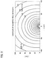
- Fig. 3 is a diagram that illustrates distribution of the magnetic field intensity formed by the one-turn loop antenna, and the horizontal axis indicates an x-axis direction in Fig. 1 while the vertical axis indicates the z-axis direction in Fig. 1 .
- Contours of the magnetic field intensity are drawn at intervals of 5 dB (specifically, 5 dB ⁇ V/m) (5 dB/div).
- the contours of the magnetic field intensity are curved. That is, the shape of the magnetic field area is accordingly a curved surface. Thus, it is difficult to form a linear and clear boundary of the communication area with the one-turn loop antenna.
- the attenuation rate of magnetic field intensity of 100 dB/dec indicated in Fig. 2 is required, for example.
- Fig. 4 is a diagram that illustrates an example of a loop antenna array for obtaining the attenuation rate of magnetic field intensity of 100 dB/dec.
- Such an attenuation rate of magnetic field intensity can be obtained by a loop antenna array including four loop antennas 1, 2A, 2B, and 3 as illustrated in Fig. 4 .
- the loop antennas 1, 2A, 2B, and 3 are arranged linearly. Currents flow in the same direction through the two loop antennas 2A and 2B arranged in the middle, but though the two loop antennas 1 and 3 arranged in both ends, currents flow in a direction opposite from that of the currents flowing through the loop antennas 2A and 2B arranged in the middle.
- One loop antenna can be seen as a magnetic dipole. Since currents of the same magnitude flow in the opposite directions through the loop antennas 1 and 2A as the dipoles, the loop antennas 1 and 2A can be seen as a quadrupole as a whole. Likewise, the loop antennas 2B and 3 can be seen as a quadrupole as a whole. Furthering this idea, since the two quadrupoles are aligned in the opposite directions, the loop antenna array of Fig. 4 can be seen as an octupole.
- the property illustrated as a quad loop in Fig. 2 is the property of the loop antenna array illustrated in Fig. 4 , and the attenuation rate of magnetic field intensity is 100 dB/dec.
- Fig. 5 is a diagram that illustrates distribution of the magnetic field intensity formed by those four loop antennas. Contours of the magnetic field intensity are drawn at intervals of 5 dB (5 dB/div).
- a part of each contour of the magnetic field intensity is linear more than that in the distribution of Fig. 3 . That is, it can be seen that there is formed the linear and clear magnetic field area.
- the linear and clear boundary of the communication area can be formed by the loop antenna array of Fig. 4 .
- Fig. 6 is a diagram that illustrates an example of a loop antenna array of a first embodiment.
- the loop antenna array of the first embodiment includes loop antennas 1 and 3 arranged in both ends and a loop antenna 2 arranged in the middle.
- the center of each of the loop antennas 1 to 3 is arranged linearly, and a distance between the centers of the loop antennas 1 and 2 and a distance between the centers of the loop antennas 2 and 3 are the same. That is, the distances between the centers of the adjacent loop antennas are the same.
- Each of the loop antennas 1 to 3 is a conductor formed in a loop shape, and is formed on the same surface of an un-illustrated plane board, or on the same plane (an xy-plane in the drawing), for example. Likewise, the later-described loop antenna array can also be formed on the same plane.
- the loop antennas 1 to 3 have the same shape, and the shape illustrated in Fig. 6 is a circle, for example. Note that the shape of each of the loop antennas 1 to 3 may be different, and the shape may be other than the circle. This is similar to the later-described loop antenna array.
- the numbers of turns of the respective loop antennas 1 to 3 are the same, and the number of turns is one, for example. Note that the number of turns may be two or greater.
- areas of regions respectively surrounded by the loop antennas 1 and 3 arranged in both ends are the same, and an area of a region surrounded by the loop antenna 2 arranged in the middle is twice the area of the region surrounded by each of the loop antennas 1 and 3 arranged in both ends.
- the loop antennas 1 to 3 are formed of a continuous conductor LN, for example.
- the + terminal as one end of the conductor LN is connected to the signal terminal of the alternating-current source E, and the - terminal as the other end of the conductor LN is connected to the GND terminal of the alternating-current source E. Since all the loop antennas 1 to 3 are formed of the continuous conductor in this way, all the loop antennas can be supplied with the currents with one alternating-current source E. Note that the magnitude of the current may be set optionally depending on the size of the required communication area.
- the conductor LN between the loop antennas 1 and 2 are crossed, and the conductor LN between the loop antennas 2 and 3 are crossed. This makes the direction of the current flowing through the loop antenna 2 arranged in the middle and the direction of the current flowing through each of the loop antennas 1 and 3 arranged in both ends opposite from each other.
- the direction of the current flowing through the loop antenna 2 arranged in the middle and the direction of the currents flowing through the loop antennas 1 and 3 arranged in both ends are opposite from each other, the magnitude of the currents flowing through the respective loop antennas 1 to 3 is the same, the numbers of turns of the respective loop antennas 1 to 3 are the same, and the area of the region surrounded by the loop antenna 2 arranged in the middle is twice the area of the region surrounded by each of the loop antennas 1 and 3 arranged in both ends.
- the magnitude m of the magnetic moment of the loop antenna 2 arranged in the middle is twice the magnitude m of the magnetic moment of each of the loop antennas 1 and 3 arranged in both ends.
- the direction of the current flowing through the loop antenna 2 arranged in the middle and the direction of the current flowing through each of the loop antennas 1 and 3 arranged in both ends are opposite from each other, the direction of the magnetic moment of the loop antenna 2 arranged in the middle and the direction of the magnetic moment of each of the loop antennas 1 and 3 arranged in both ends are opposite from each other. That is, taking into account of the direction, the sum of the magnetic moments of the loop antennas 1 to 3 is zero. Making the sum of the magnetic moments of the whole loop antenna array zero in this way can reduce the magnetic field intensity in the distance. In other words, this makes it possible to rapidly attenuate the magnetic field in the distance.
- the loop antenna array of the first embodiment can be thought as the loop antenna array illustrated in Fig. 4 in which the loop antennas 2A and 2B are replaced with the loop antenna 2. That is, the loop antenna array of the first embodiment is comparable to the loop antenna array of Fig. 4 , or the octupole in which the two quadrupoles are aligned in the opposite directions, and an effect comparable to the effect of the loop antenna array of Fig. 4 can be obtained.
- the property illustrated as a triple loop in Fig. 2 is the property of the magnetic field intensity formed by the loop antenna array of the first embodiment, and the attenuation rate of magnetic field intensity is 100 dB/dec. That is, the attenuation rate of this magnetic field intensity is comparable to the attenuation rate of magnetic field intensity of the loop antenna of Fig. 4 illustrated as the quad loop. As a result, the clear boundary of the communication area can be formed like the case of the loop antenna array of Fig. 4 .
- Fig. 7 is a diagram that illustrates distribution of the magnetic field intensity formed by the loop antenna array of the first embodiment, and the horizontal axis indicates the x-axis direction in Fig. 6 while the vertical axis indicates the z-axis direction in Fig. 6 . Contours of the magnetic field intensity are drawn at intervals of 5 dB (5 dB/div) . Comparing with the distribution of magnetic field intensity illustrated in Fig. 5 , the distribution of magnetic field intensity formed by the loop antenna array of the first embodiment is substantially similar to the distribution of magnetic field intensity illustrated in Fig. 5 , and the contours of the magnetic field intensity is partially linear.
- While the number of the antennas in the loop antenna array illustrated in Fig. 4 is four, the number of the antennas in the loop antenna array of the first embodiment illustrated in Fig. 6 is three.
- the loop antenna array of the first embodiment can form the clear boundary of the communication area similarly to the loop antenna array illustrated in Fig. 4 .
- the linear boundary of the communication area can be formed. That is, the relatively small number of loop antennas can form the clear boundary of the communication area that one loop antenna cannot form.
- the relatively small number of loop antennas can form the clear boundary of the communication area that one loop antenna cannot form.
- the linear boundary of the communication area can be formed.
- the shape of the distribution of magnetic field intensity does not depend on the shape of the loop antenna.
- the shape of the loop antenna may be any one of a circle, a square, a rectangle, an oval, a fan shape, a triangle, a semicircle, a spiral, and a helix.
- the shape of the loop antenna only has to be a shape that can form the magnetic moment when the current flows. This is similar to the later-described loop antenna array.
- the loop antenna array may allow many shapes such as a circle (e.g., loop antenna 1), a square (e.g., loop antenna 2), and a rectangle (e.g., loop antenna 3) to coexist. That is, the three loop antennas 1 to 3 may either be in the same shape or in different shapes.
- All the loop antennas may not be necessarily formed of the continuous conductor. This is similar to the later-described loop antenna array.
- the loop antennas 1 to 3 may not be formed of the continuous conductor LN.
- a pair of the + terminal and the - terminal is provided in each of the loop antennas 1, 2, and 3.
- the + terminals of the loop antennas 1 and 3 and the - terminal of the loop antenna 2 are connected to the signal terminal of the alternating-current source E
- the - terminals of the loop antennas 1 and 3 and the + terminal of the loop antenna 2 are connected to the GND terminal of the alternating-current source E.
- the direction of the current flowing through the loop antenna 2 arranged in the middle and the direction of the currents flowing through the loop antennas 1 and 3 arranged in both ends become opposite from each other.
- the sum of the magnetic moments becomes zero.
- a pair of the + terminal and the - terminal is provided in each of the loop antennas 1, 2, and 3, and two alternating-current sources E1 and E2 are provided. Then, the + terminals of the loop antennas 1 and 3 are connected to the signal terminal of the alternating-current source E1 while the - terminals of the loop antennas 1 and 3 are connected to the GND terminal of the alternating-current source E1, and the + terminal and the - terminal of the loop antenna 2 are respectively connected to the signal terminal and the GND terminal of the alternating-current source E2.
- the signal terminal of the alternating-current source E1 When the signal terminal of the alternating-current source E1 has a positive voltage, they are synchronized such that the signal terminal of the alternating-current source E2 has a negative voltage. In this way, the direction of the current flowing through the loop antenna 2 arranged in the middle and the direction of the currents flowing through the loop antennas 1 and 3 arranged in both ends become opposite from each other. Then, the sum of the magnetic moments becomes zero.
- Fig. 10 is a diagram that illustrates relationship between an attenuation rate of magnetic field intensity and a standardized distance in the z-axis direction in the first embodiment.
- the vertical axis is the attenuation rate of magnetic field intensity [dB/dec] while the horizontal axis is the standardized distance z/a in the z-axis direction in Fig. 6 .
- z is a distance (predetermined distance) in the z-axis direction from the center of the loop antenna 2 arranged in the middle in Fig. 6 .
- a is a distance between the center of the loop antenna 2 arranged in the middle and the center of each of the loop antennas 1 and 3 arranged in both ends. That is, the above-described predetermined distance is z, a is the distance between the centers of adjacent loop antennas, and z/a is called the standardized distance.
- the attenuation rate of magnetic field intensity of 90 dB/dec or greater can be obtained in a range of z/a ⁇ 2.50.
- the attenuation rate of magnetic field intensity of 70 dB/dec or greater can be obtained in a range of z/a ⁇ 1.06.
- the attenuation rate of magnetic field intensity becomes gradually close to 80 dB/dec in a loop antenna array (double loop) including two loop antennas of Fig. 1 . That is, the attenuation rate of magnetic field intensity cannot be greater than 80 dB/dec in the double loop.
- a in a case where the attenuation rate of magnetic field intensity of 80 dB/dec or greater at a position having the predetermined distance z from the center of the loop antenna 2 arranged in the middle is required, a only has to be set such that z/a ⁇ 1.6. Arrangement of each loop antenna to which a (i.e., a distance between the centers of adjacent loop antennas) is set such that z/a ⁇ 1.6 makes it possible to obtain the attenuation rate of magnetic field intensity of 80 dB/dec at the above-described position. Thus, a clearer boundary of the communication area can be formed.
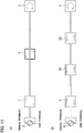
- Fig. 11(a) is a diagram that illustrates an example of a loop antenna array of a second embodiment.
- Fig. 11(b) is a diagram that illustrates an example of a loop antenna array of a comparative example of the second embodiment.
- the sum of the magnetic moments is made zero by making the area of the region surrounded by the loop antenna 2 arranged in the middle twice the area of the region surrounded by each of the loop antennas 1 and 3 arranged in both ends.
- the sum of the magnetic moments is made zero by making the number of turns of the loop antenna 2 arranged in the middle equal to the sum of the numbers of turns of the loop antennas 1 and 3 arranged in both ends.
- the number of turns of the loop antenna 2 arranged in the middle is two, and each number of turns of the loop antennas 1 and 3 arranged in both ends is one.
- the numbers of turns are not limited to the above-mentioned values as long as the number of turns of the loop antenna 2 arranged in the middle is equal to the sum of the numbers of turns of the loop antennas 1 and 3 arranged in both ends.
- the areas of the regions respectively surrounded by the loop antennas 1 to 3 are the same, the magnitude of the currents flowing through the respective loop antennas 1 to 3 is the same, and the number of turns of the loop antenna 2 arranged in the middle is equal to the sum of the numbers of turns of the loop antennas 1 and 3 arranged in both ends. As a result, the sum of the magnetic moments becomes zero.
- each loop antenna may have a different shape.
- the value of the area may be set optionally as long as the areas of the regions respectively surrounded by the loop antennas 1 to 3 are the same.
- the magnitude of the currents may be set optionally as long as the magnitude of the currents flowing through the respective loop antennas 1 to 3 is the same.
- the loop antenna array of the second embodiment can be thought as the loop antenna array illustrated in Fig. 11(b) in which the loop antennas 2A and 2B are replaced with the loop antenna 2. While the number of the antennas in the loop antenna array illustrated in Fig. 11(b) is four, the number of the antennas in the loop antenna array of the second embodiment illustrated in Fig. 11(a) is three.
- the relatively small number of loop antennas can form the clear boundary of the communication area that one loop antenna cannot form.
- the linear boundary of the communication area can be formed.
- Fig. 12(a) is a diagram that illustrates an example of a loop antenna array of a third embodiment.
- Fig. 12(b) is a diagram that illustrates an example of a loop antenna array of a modification example of the third embodiment.
- the sum of the magnetic moments is made zero by making the area of the region surrounded by the loop antenna 2 arranged in the middle twice the area of the region surrounded by each of the loop antennas 1 and 2 arranged in both ends.
- the sum of the magnetic moments is made zero by making the magnitude of the current flowing through the loop antenna 2 arranged in the middle twice the magnitude of each of the currents flowing though the loop antennas 1 and 3 arranged in both ends.
- a pair of the + terminal and the - terminal is provided in each of the loop antennas 1, 2, and 3, and two alternating-current sources E1 and E2 are provided, for example.
- the + terminals of the loop antennas 1 and 3 are connected to the signal terminal of the alternating-current source E1 while the - terminals of the loop antennas 1 and 3 are connected to the GND terminal of the alternating-current source E1.
- the + terminal and the - terminal of the loop antenna 2 are respectively connected to the signal terminal and the GND terminal of the alternating-current source E2.
- the numbers of turns of the respective loop antennas 1 to 3 are the same, the areas of the regions respectively surrounded by the loop antennas 1 to 3 are the same, and the magnitude of the current flowing through the loop antenna 2 arranged in the middle is twice the magnitude of the current flowing through each of the loop antennas 1 and 3 arranged in both ends.
- the magnitude of the current may be set optionally as long as the magnitude of the current flowing through the loop antenna 2 arranged in the middle is twice the magnitude of the current flowing through each of the loop antennas 1 and 3 arranged in both ends.
- the value of the area may be set optionally as long as the areas of the regions respectively surrounded by the loop antennas 1 to 3 are the same.
- the number of turns may be set optionally as long as the numbers of turns of the respective loop antennas 1 to 3 are the same.
- the sum of the magnetic moments is zero, and the similar action effects as that of the first embodiment can be obtained. That is, the relatively small number of loop antennas can form the clear boundary of the communication area that one loop antenna cannot form. In addition, the linear boundary of the communication area can be formed.
- the loop antennas 1 and 3 may be formed of the continuous conductor, for example.
- the + terminal as one end of the conductor is connected to the signal terminal of the alternating-current source E1, and the - terminal as the other end of the conductor is connected to the GND terminal of the alternating-current source E1.
- Fig. 13 is a diagram that illustrates an example of a loop antenna array of a fourth embodiment.
- the alternating-current source E1 supplies the currents to the loop antennas 1 and 3 arranged in both ends, and the alternating-current source E2 supplies the current to the loop antenna 2 arranged in the middle.
- the alternating-current source E supplies the current to the loop antenna 2 arranged in the middle, and the current flowing through the loop antenna 2 diverges and flows into each of the loop antennas 1 and 3 arranged in both ends.
- a pair of the + terminal and the - terminal is provided in each of the loop antennas 1, 2, and 3, and the alternating-current source E is provided. Then, the + terminal of the loop antenna 2 is connected to the signal terminal of the alternating-current source E, and the - terminal of the loop antenna 2 is connected to the + terminals of the loop antennas 1 and 3. Then, the - terminals of the loop antennas 1 and 3 are connected to the GND terminal of the alternating-current source E.
- the current of magnitude I flows through the loop antenna 2
- this current diverges into each of the loop antennas 1 and 3, and then the current of magnitude 0.51 flows through each of the loop antennas 1 and 3. That is, the magnitude of the current flowing through the loop antenna 2 arranged in the middle is twice the magnitude of the current flowing through each of the loop antennas 1 and 3 arranged in both ends.
- the sum of the magnetic moments is zero, and the similar action effects as that of the second embodiment can be obtained. That is, the relatively small number of loop antennas can form the clear boundary of the communication area that one loop antenna cannot form. In addition, the linear boundary of the communication area can be formed.
- the loop antennas can be supplied with the currents with one alternate-current source E.
- Fig. 14(a) is a diagram that illustrates an example of a loop antenna array of a fifth embodiment.
- Fig. 14(b) is a diagram that illustrates an example of a loop antenna array of a comparative example of the fifth embodiment.
- the loop antenna array of the fifth embodiment includes two loop antenna arrays of the second embodiment illustrated in Fig. 11 (each loop antenna array includes three loop antennas 1 to 3).
- the loop antennas are formed of the continuous conductor LN.
- the + terminal as one end of the conductor LN is connected to the signal terminal of the alternating-current source E, and the - terminal as the other end of the conductor LN is connected to the GND terminal of the alternating-current source E. Since all the loop antennas are formed of the continuous conductor LN, the loop antennas can be supplied with the currents with one alternating-current source E.
- a group of the (n - 1)th power of 2 loop antenna arrays is a unitary loop antenna array.
- the 0th power of 2 (one) loop antenna array is the unitary loop antenna array.
- a loop antenna array on the left side of Fig. 14 (a) (loop antennas 1 to 3) is a first unitary loop antenna array A1
- a loop antenna array on the right side of Fig. 14(a) (loop antennas 1 to 3) is a second unitary loop antenna array A2.
- the first unitary loop antenna array and the second unitary loop antenna array can be opposite.
- the direction of the current flowing through the loop antenna arranged on one end (e.g., the loop antenna 1 on the left end) in the first unitary loop antenna array A1 and the direction of the current flowing through the loop antenna arranged on the same position as the above-mentioned one end (the same left end) (e.g., the loop antenna 1 on the left end) in the second unitary loop antenna array A2 are opposite from each other. Also in the fifth embodiment, the sum of the magnetic moments becomes zero.
- the loop antenna array of the fifth embodiment is comparable to the 16-pole in which the octupoles like the loop antenna array of Fig. 6 are arranged in the opposite directions, and its attenuation rate of magnetic field intensity is 120 dB/dec, which is greater than 100 dB/dec obtained by the octupole.
- the loop antenna array of the fifth embodiment it is possible to form the boundary of the communication area clearer than the boundary of the communication area formed by the loop antenna arrays of the first to fourth embodiments.
- the loop antenna array of the fifth embodiment can be thought as the loop antenna array illustrated in Fig. 14(b) in which the loop antennas 2A and 2B are replaced with the loop antenna 2.
- the number of the antennas is small, the sum of the magnetic moments is zero, and the similar action effects as that of the loop antenna array illustrated in Fig. 14 (b) can be obtained.
- the relatively small number of loop antennas can form the clear boundary of the communication area.
- the linear boundary of the communication area can be formed.
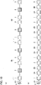
- Fig. 15(a) is a diagram that illustrates an example of a loop antenna array of a sixth embodiment.
- Fig. 15(b) is a diagram that illustrates an example of a loop antenna array of a comparative example of the sixth embodiment.
- the loop antenna array of the sixth embodiment includes four loop antenna arrays of the second embodiment (each loop antenna array includes three loop antennas) .
- the loop antenna array of the sixth embodiment includes two loop antenna arrays of the fifth embodiment (each loop antenna array includes six loop antennas).
- the loop antennas are formed of the continuous conductor LN.
- the + terminal as one end of the conductor LN is connected to the signal terminal of the alternating-current source E, and the - terminal as the other end of the conductor LN is connected to the GND terminal of the alternating-current source E. Since all the loop antennas are formed of the continuous conductor LN, the loop antennas can be supplied with the currents with one alternating-current source E.
- a loop antenna array on the left side of Fig. 15(a) (six loop antennas) is a first unitary loop antenna array B1
- a loop antenna array on the right side of Fig. 15 (a) (six loop antennas) is a second unitary loop antenna array B2.
- the first unitary loop antenna array and the second unitary loop antenna array can be opposite.
- the direction of the current flowing through the loop antenna on one end (e.g., the loop antenna 1 on the left end) in the first unitary loop antenna array B1 and the direction of the current flowing through the loop antenna arranged on the same position as the above-mentioned one end (the same left end) (e.g., the loop antenna 1 on the left end) in the second unitary loop antenna array B2 are opposite from each other. Also in the sixth embodiment, the sum of the magnetic moments becomes zero.
- the loop antenna array of the sixth embodiment is comparable to the 32-pole in which the 16-poles comparable to the loop antenna array of the fifth embodiment are arranged in the opposite directions.
- the attenuation rate of magnetic field intensity of the loop antenna array of the sixth embodiment is 140 dB/dec, which is greater than 120 dB/dec of the attenuation rate of magnetic field intensity of the fifth embodiment.
- the loop antenna array of the sixth embodiment it is possible to form the boundary of the communication area clearer than the boundary of the communication area formed by the loop antenna array of the fifth embodiment.
- the loop antenna array of the sixth embodiment can be thought as the loop antenna array illustrated in Fig. 15 (b) in which the loop antennas 2A and 2B are replaced with the loop antenna 2.
- the number of the antennas is small, the sum of the magnetic moments is zero, and the similar action effects as that of the loop antenna array illustrated in Fig. 15 (b) can be obtained.
- the relatively small number of loop antennas can form the clear boundary of the communication area.
- the linear boundary of the communication area can be formed.
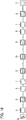
- Fig. 16 is a diagram that illustrates an example of a loop antenna array of a seventh embodiment.
- the loop antenna array of the seventh embodiment is the loop antenna array of the sixth embodiment in which adjacent two loop antennas through which currents flow in the same direction are replaced with one loop antenna through which currents flow in the same direction as that of the mentioned currents and in which the magnitude of the magnetic moment is twice the magnetic moment of each of the concerned adjacent loop antennas.
- the loop antenna 3 on the right end of the first unitary loop antenna array B1 and the loop antenna 1 on the left end of the second unitary loop antenna array B2 are next to each other, and additionally, the direction of the currents is the same.
- the loop antenna array of the seventh embodiment includes one loop antenna 21 through which the currents flow in the same direction and in which the magnitude of the magnetic moment is twice the magnetic moment of each of the loop antennas 1 and 3.
- the number of turns of the loop antenna 21 is equal to the sum of the numbers of turns of the loop antennas 1 and 3.
- the areas of the regions respectively surrounded by the loop antennas 1, 3, and 21 are the same, and the magnitude of the currents flowing through the respective loop antennas 1, 3, and 21 are the same.
- the magnetic moment of the loop antenna 21 becomes the sum of the magnetic moments of the loop antennas 1 and 3. Also in the seventh embodiment, the sum of the magnetic moments becomes zero.
- the loop antenna array of the seventh embodiment is comparable to the 32-pole in which the 16-poles are arranged in the opposite directions, and its attenuation rate of magnetic field intensity is greater than the attenuation rate of magnetic field intensity of the fifth embodiment.
- the loop antenna array of the seventh embodiment it is possible to form the boundary of the communication area clearer than the boundary of the communication area formed by the loop antenna array of the fifth embodiment.
- the replacement of the loop antennas 1 and 3 with the loop antenna 21 makes it possible to reduce the number of the loop antennas.
- the loop antennas may not be formed of the continuous conductor, and different conductors may be used as the case of Fig. 9 and the like, for example.
- the magnitude of the currents flowing through the respective loop antennas 1 to 3 may be the same, the numbers of turns of the respective loop antennas 1 to 3 may be the same, and the area of the region surrounded by the loop antenna 2 may be twice the area of the region surrounded by each of the loop antennas 1 and 3.
- the magnitude of the current flowing through the loop antenna 2 may be twice the magnitude of the current flowing through each of the loop antennas 1 and 3, the numbers of turns of the respective loop antennas 1 to 3 may be the same, and the areas of the regions respectively surrounded by the loop antennas 1 to 3 may be the same.
Landscapes
- Engineering & Computer Science (AREA)
- Computer Networks & Wireless Communication (AREA)
- Signal Processing (AREA)
- Variable-Direction Aerials And Aerial Arrays (AREA)
Abstract
Description
- The present invention relates to a loop antenna array capable of forming a clear boundary of a communication area.
- A demand for a radio communication system with a purposely limited communication area has recently been increasing. An electric field communication system utilizing an electric field is disclosed in
Patent document 1 as such a radio communication system. - Patent document 1: Japanese Patent Application Publication No.
2007-174570 - In an electric field communication system, only a terminal device in an area around an installed access point device can communicate with the access point device. However, the distribution of the electric field around the access point device heavily depends on the installation environment or orientation of a user holding the terminal device. It has been thus difficult to form a clear boundary of a communication area by the electric field communication system. As a result, failure of communication of terminal devices at positions where the communication should be made or the opposite case can happen, and a stable and reliable radio communication system cannot be constructed.
- The use of the electric field as a communication medium can be thought as one of the causes of such problems. This is because the distribution of the electric field is affected a lot by a surrounding conductor or dielectric.
- The present invention is made in view of the above-described problems, and an objective of the present invention is to provide a loop antenna array capable of forming a clear boundary of a communication area.
- In order to solve the above-described problems, the loop antenna array of the present invention includes three loop antennas, in which a direction of a current flowing through the loop antenna arranged in the middle and a direction of a current flowing through each of the loop antennas arranged in both sides are opposite from each other, and the sum of magnetic moments of the loop antennas is zero.
- According to the loop antenna array of the present invention, a clear boundary of a communication area can be formed.
-
-
Fig. 1 is a diagram that illustrates an example of a one-turn loop antenna. -
Fig. 2 is a diagram that illustrates relationship between a distance from the loop antenna in a z-axis direction and magnetic field intensity. -
Fig. 3 is a diagram that illustrates distribution of the magnetic field intensity formed by the one-turn loop antenna. -
Fig. 4 is a diagram that illustrates an example of a loop antenna array for obtaining an attenuation rate of magnetic field intensity of 100 dB/dec. -
Fig. 5 is a diagram that illustrates distribution of the magnetic field intensity formed by four loop antennas. -
Fig. 6 is a diagram that illustrates an example of a loop antenna array of a first embodiment. -
Fig. 7 is a diagram that illustrates distribution of the magnetic field intensity formed by the loop antenna array of the first embodiment. -
Fig. 8 is a diagram that illustrates an example of a loop antenna array in which the shape of the loop antenna is changed. -
Fig. 9 is a diagram that illustrates an example of a loop antenna array as a modification of the first embodiment. -
Fig. 10 is a diagram that illustrates relationship between an attenuation rate of magnetic field intensity and a standardized distance in the z-axis direction in the first embodiment. -
Fig. 11(a) is a diagram that illustrates an example of a loop antenna array of a second embodiment, andFig. 11(b) is a diagram that illustrates an example of a loop antenna array of a comparative example of the second embodiment. -
Fig. 12(a) is a diagram that illustrates an example of a loop antenna array of a third embodiment, andFig. 12 (b) is a diagram that illustrates an example of a loop antenna array of a modification of the third embodiment. -
Fig. 13 is a diagram that illustrates an example of a loop antenna array of a fourth embodiment. -
Fig. 14(a) is a diagram that illustrates an example of a loop antenna array of a fifth embodiment, andFig. 14 (b) is a diagram that illustrates an example of a loop antenna array of a comparative example of the fifth embodiment. -
Fig. 15(a) is a diagram that illustrates an example of a loop antenna array of a sixth embodiment, andFig. 15 (b) is a diagram that illustrates an example of a loop antenna array of a comparative example of the sixth embodiment. -
Fig. 16 is a diagram that illustrates an example of a loop antenna array of a seventh embodiment. - Hereinafter, embodiments of the present invention are described with reference to the drawings.
- A loop antenna array of this embodiment is a loop antenna array including multiple loop antennas as a type of a magnetic field antenna.
- A low-frequency magnetic field (magnetic field of about 10 MHz or below) formed by the loop antenna array has a feature that interaction with a human body or a surrounding environment is significantly lower than that of an electric field. Thus, that low-frequency magnetic field is appropriate as a communication medium for forming a clear boundary of a communication area. If sharp distribution of magnetic field intensity in which the magnetic field intensity rapidly attenuates at the boundary of the communication area can be formed with the loop antenna array, the reliability of a radio communication system with a limited communication area can be increased.
- A magnetic field antenna generally used for forming a magnetic field area is a one-turn loop antenna.
-
Fig. 1 is a diagram that illustrates an example of the one-turn loop antenna. For example, a + terminal of the loop antenna is connected to a signal terminal of an alternating-current source E, and a - terminal is connected to a GND terminal of the alternating-current source E. This allows an alternating-current to flow through the loop antenna. -
Fig. 2 is a diagram that illustrates relationship between a distance from the loop antenna in a z-axis direction (z[cm]) and magnetic field intensity [dBµV/m]. - The property illustrated as a single loop in
Fig. 2 is the property of the magnetic field intensity formed by the one-turn loop antenna, and an attenuation rate of the magnetic field intensity is 60 dB/dec. The attenuation rate of magnetic field intensity is an index indicating clarity of the boundary of the communication area, and it can be said that the higher the attenuation rate of magnetic field intensity, the clearer the boundary of the communication area. -
Fig. 3 is a diagram that illustrates distribution of the magnetic field intensity formed by the one-turn loop antenna, and the horizontal axis indicates an x-axis direction inFig. 1 while the vertical axis indicates the z-axis direction inFig. 1 . Contours of the magnetic field intensity are drawn at intervals of 5 dB (specifically, 5 dBµV/m) (5 dB/div). - As illustrated in
Fig. 3 , the contours of the magnetic field intensity are curved. That is, the shape of the magnetic field area is accordingly a curved surface. Thus, it is difficult to form a linear and clear boundary of the communication area with the one-turn loop antenna. - In order to form the linear and clear boundary of the communication area, the attenuation rate of magnetic field intensity of 100 dB/dec indicated in
Fig. 2 is required, for example. -
Fig. 4 is a diagram that illustrates an example of a loop antenna array for obtaining the attenuation rate of magnetic field intensity of 100 dB/dec. - Such an attenuation rate of magnetic field intensity can be obtained by a loop antenna array including four
loop antennas Fig. 4 . Theloop antennas loop antennas loop antennas loop antennas - One loop antenna can be seen as a magnetic dipole. Since currents of the same magnitude flow in the opposite directions through the
loop antennas loop antennas loop antennas Fig. 4 can be seen as an octupole. - The property illustrated as a quad loop in
Fig. 2 is the property of the loop antenna array illustrated inFig. 4 , and the attenuation rate of magnetic field intensity is 100 dB/dec. -
Fig. 5 is a diagram that illustrates distribution of the magnetic field intensity formed by those four loop antennas. Contours of the magnetic field intensity are drawn at intervals of 5 dB (5 dB/div). - In
Fig. 5 , a part of each contour of the magnetic field intensity is linear more than that in the distribution ofFig. 3 . That is, it can be seen that there is formed the linear and clear magnetic field area. Thus, the linear and clear boundary of the communication area can be formed by the loop antenna array ofFig. 4 . - However, since the configuration of the loop antenna array of
Fig. 4 requires four loop antennas, there is a problem that the loop antenna array becomes complicated and expensive. -
Fig. 6 is a diagram that illustrates an example of a loop antenna array of a first embodiment. - As illustrated in
Fig. 6 , the loop antenna array of the first embodiment includesloop antennas loop antenna 2 arranged in the middle. The center of each of theloop antennas 1 to 3 is arranged linearly, and a distance between the centers of theloop antennas loop antennas - Each of the
loop antennas 1 to 3 is a conductor formed in a loop shape, and is formed on the same surface of an un-illustrated plane board, or on the same plane (an xy-plane in the drawing), for example. Likewise, the later-described loop antenna array can also be formed on the same plane. - The
loop antennas 1 to 3 have the same shape, and the shape illustrated inFig. 6 is a circle, for example. Note that the shape of each of theloop antennas 1 to 3 may be different, and the shape may be other than the circle. This is similar to the later-described loop antenna array. - The numbers of turns of the
respective loop antennas 1 to 3 are the same, and the number of turns is one, for example. Note that the number of turns may be two or greater. - For example, areas of regions respectively surrounded by the
loop antennas loop antenna 2 arranged in the middle is twice the area of the region surrounded by each of theloop antennas - The
loop antennas 1 to 3 are formed of a continuous conductor LN, for example. The + terminal as one end of the conductor LN is connected to the signal terminal of the alternating-current source E, and the - terminal as the other end of the conductor LN is connected to the GND terminal of the alternating-current source E. Since all theloop antennas 1 to 3 are formed of the continuous conductor in this way, all the loop antennas can be supplied with the currents with one alternating-current source E. Note that the magnitude of the current may be set optionally depending on the size of the required communication area. - For example, the conductor LN between the
loop antennas loop antennas loop antenna 2 arranged in the middle and the direction of the current flowing through each of theloop antennas - That is, in timing when the signal terminal of the alternating-current source E has a positive voltage, as seen from the direction of penetrating through the
loop antennas 1 to 3, or from the z-axis direction, clockwise currents flow through theloop antennas loop antenna 2. Meanwhile, in timing when the signal terminal of the alternating-current source E has a negative voltage, counterclockwise currents flow through theloop antennas 1 to 3, and a clockwise current flows through theloop antenna 2. - Note that, since all the
loop antennas 1 to 3 are formed with the continuous conductor LN, the magnitude of the currents flowing through theloop antennas 1 to 3 is the same. - In general, the amplitude of magnetic field intensity generated in the distance by the loop antenna is proportional to the magnitude (absolute value) m of a magnetic dipole moment vector (hereinafter, called a magnetic moment). That m is obtained from the following equation.

- In the first embodiment, the direction of the current flowing through the
loop antenna 2 arranged in the middle and the direction of the currents flowing through theloop antennas respective loop antennas 1 to 3 is the same, the numbers of turns of therespective loop antennas 1 to 3 are the same, and the area of the region surrounded by theloop antenna 2 arranged in the middle is twice the area of the region surrounded by each of theloop antennas loop antenna 2 arranged in the middle is twice the magnitude m of the magnetic moment of each of theloop antennas loop antenna 2 arranged in the middle and the direction of the current flowing through each of theloop antennas loop antenna 2 arranged in the middle and the direction of the magnetic moment of each of theloop antennas loop antennas 1 to 3 is zero. Making the sum of the magnetic moments of the whole loop antenna array zero in this way can reduce the magnetic field intensity in the distance. In other words, this makes it possible to rapidly attenuate the magnetic field in the distance. - The loop antenna array of the first embodiment can be thought as the loop antenna array illustrated in
Fig. 4 in which theloop antennas loop antenna 2. That is, the loop antenna array of the first embodiment is comparable to the loop antenna array ofFig. 4 , or the octupole in which the two quadrupoles are aligned in the opposite directions, and an effect comparable to the effect of the loop antenna array ofFig. 4 can be obtained. - The property illustrated as a triple loop in
Fig. 2 is the property of the magnetic field intensity formed by the loop antenna array of the first embodiment, and the attenuation rate of magnetic field intensity is 100 dB/dec. That is, the attenuation rate of this magnetic field intensity is comparable to the attenuation rate of magnetic field intensity of the loop antenna ofFig. 4 illustrated as the quad loop. As a result, the clear boundary of the communication area can be formed like the case of the loop antenna array ofFig. 4 . -
Fig. 7 is a diagram that illustrates distribution of the magnetic field intensity formed by the loop antenna array of the first embodiment, and the horizontal axis indicates the x-axis direction inFig. 6 while the vertical axis indicates the z-axis direction inFig. 6 . Contours of the magnetic field intensity are drawn at intervals of 5 dB (5 dB/div) . Comparing with the distribution of magnetic field intensity illustrated inFig. 5 , the distribution of magnetic field intensity formed by the loop antenna array of the first embodiment is substantially similar to the distribution of magnetic field intensity illustrated inFig. 5 , and the contours of the magnetic field intensity is partially linear. - While the number of the antennas in the loop antenna array illustrated in
Fig. 4 is four, the number of the antennas in the loop antenna array of the first embodiment illustrated inFig. 6 is three. - Although the number of the antennas is small, the loop antenna array of the first embodiment can form the clear boundary of the communication area similarly to the loop antenna array illustrated in
Fig. 4 . In addition, the linear boundary of the communication area can be formed. That is, the relatively small number of loop antennas can form the clear boundary of the communication area that one loop antenna cannot form. - As described above, according to the loop antenna array of the first embodiment, the relatively small number of loop antennas can form the clear boundary of the communication area that one loop antenna cannot form. In addition, the linear boundary of the communication area can be formed.
- Note that the shape of the distribution of magnetic field intensity does not depend on the shape of the loop antenna. Thus, the shape of the loop antenna may be any one of a circle, a square, a rectangle, an oval, a fan shape, a triangle, a semicircle, a spiral, and a helix. The shape of the loop antenna only has to be a shape that can form the magnetic moment when the current flows. This is similar to the later-described loop antenna array.
- For example, as illustrated in
Fig. 8 , the loop antenna array may allow many shapes such as a circle (e.g., loop antenna 1), a square (e.g., loop antenna 2), and a rectangle (e.g., loop antenna 3) to coexist. That is, the threeloop antennas 1 to 3 may either be in the same shape or in different shapes. - All the loop antennas may not be necessarily formed of the continuous conductor. This is similar to the later-described loop antenna array. For example, in the first embodiment, the
loop antennas 1 to 3 may not be formed of the continuous conductor LN. For example, as illustrated inFig. 9(a) , a pair of the + terminal and the - terminal is provided in each of theloop antennas loop antennas loop antenna 2 are connected to the signal terminal of the alternating-current source E, and the - terminals of theloop antennas loop antenna 2 are connected to the GND terminal of the alternating-current source E. In this way, the direction of the current flowing through theloop antenna 2 arranged in the middle and the direction of the currents flowing through theloop antennas - Otherwise, as illustrated in
Fig. 9(b) , a pair of the + terminal and the - terminal is provided in each of theloop antennas loop antennas loop antennas loop antenna 2 are respectively connected to the signal terminal and the GND terminal of the alternating-current source E2. When the signal terminal of the alternating-current source E1 has a positive voltage, they are synchronized such that the signal terminal of the alternating-current source E2 has a negative voltage. In this way, the direction of the current flowing through theloop antenna 2 arranged in the middle and the direction of the currents flowing through theloop antennas -
Fig. 10 is a diagram that illustrates relationship between an attenuation rate of magnetic field intensity and a standardized distance in the z-axis direction in the first embodiment. The vertical axis is the attenuation rate of magnetic field intensity [dB/dec] while the horizontal axis is the standardized distance z/a in the z-axis direction inFig. 6 . - z is a distance (predetermined distance) in the z-axis direction from the center of the
loop antenna 2 arranged in the middle inFig. 6 . a is a distance between the center of theloop antenna 2 arranged in the middle and the center of each of theloop antennas - As illustrated in
Fig. 10 , when z/a is small, or around the loop antenna array, only the attenuation rate of magnetic field intensity of about 60 dB/dec can be obtained like the case of the loop antenna ofFig. 1 . When z/a becomes greater, or as being further from the center the loop antenna array, the attenuation rate of the magnetic field is increased and, eventually, gradually close to 100 dB/dec. - As illustrated in
Fig. 10 , the attenuation rate of magnetic field intensity of 90 dB/dec or greater can be obtained in a range of z/a ≥ 2.50. In addition, the attenuation rate of magnetic field intensity of 70 dB/dec or greater can be obtained in a range of z/a ≥ 1.06. Thus, when 90 dB/dec or greater is required, a should be set such that z/a ≥ 2.50, and when 70 dB/dec or greater is required, a should be set such that z/a ≥ 1.06. - It is known that the attenuation rate of magnetic field intensity becomes gradually close to 80 dB/dec in a loop antenna array (double loop) including two loop antennas of
Fig. 1 . That is, the attenuation rate of magnetic field intensity cannot be greater than 80 dB/dec in the double loop. - In the loop antenna array of the first embodiment, this attenuation rate of magnetic field intensity of 80 dB/dec can be obtained when z/a = 1.56. That is, if a is set at least such that z/a ≥ 1.6 in the loop antenna array of the first embodiment, the maximum value of the attenuation rate of magnetic field intensity that can be obtained with the double loop, or the attenuation rate of magnetic field intensity of 80 dB/dec or greater, can be obtained.
- Thus, in the first embodiment, in a case where the attenuation rate of magnetic field intensity of 80 dB/dec or greater at a position having the predetermined distance z from the center of the
loop antenna 2 arranged in the middle is required, a only has to be set such that z/a ≥ 1.6. Arrangement of each loop antenna to which a (i.e., a distance between the centers of adjacent loop antennas) is set such that z/a ≥ 1.6 makes it possible to obtain the attenuation rate of magnetic field intensity of 80 dB/dec at the above-described position. Thus, a clearer boundary of the communication area can be formed. - Note that, also in the later-described loop antenna array, it is preferable to set a so as to achieve this relationship (z/a ≥ 1.6) when the attenuation rate of magnetic field intensity of 80 dB/dec is required.
-
Fig. 11(a) is a diagram that illustrates an example of a loop antenna array of a second embodiment.Fig. 11(b) is a diagram that illustrates an example of a loop antenna array of a comparative example of the second embodiment. - In the first embodiment, the sum of the magnetic moments is made zero by making the area of the region surrounded by the
loop antenna 2 arranged in the middle twice the area of the region surrounded by each of theloop antennas - On the other hand, in the loop antenna array of the second embodiment illustrated in
Fig. 11(a) , the sum of the magnetic moments is made zero by making the number of turns of theloop antenna 2 arranged in the middle equal to the sum of the numbers of turns of theloop antennas - For example, the number of turns of the
loop antenna 2 arranged in the middle is two, and each number of turns of theloop antennas loop antenna 2 arranged in the middle is equal to the sum of the numbers of turns of theloop antennas - As described above, in the second embodiment, the areas of the regions respectively surrounded by the
loop antennas 1 to 3 are the same, the magnitude of the currents flowing through therespective loop antennas 1 to 3 is the same, and the number of turns of theloop antenna 2 arranged in the middle is equal to the sum of the numbers of turns of theloop antennas - Although the example illustrated in
Fig. 11(a) has the square loop antenna, each loop antenna may have a different shape. In addition, the value of the area may be set optionally as long as the areas of the regions respectively surrounded by theloop antennas 1 to 3 are the same. - Moreover, the magnitude of the currents may be set optionally as long as the magnitude of the currents flowing through the
respective loop antennas 1 to 3 is the same. - The loop antenna array of the second embodiment can be thought as the loop antenna array illustrated in
Fig. 11(b) in which theloop antennas loop antenna 2. While the number of the antennas in the loop antenna array illustrated inFig. 11(b) is four, the number of the antennas in the loop antenna array of the second embodiment illustrated inFig. 11(a) is three. - In the second embodiment, although the number of the antennas is small, the sum of the magnetic moments is zero, and the similar action effects as that of the first embodiment can be obtained. Thus, the relatively small number of loop antennas can form the clear boundary of the communication area that one loop antenna cannot form. In addition, the linear boundary of the communication area can be formed.
-
Fig. 12(a) is a diagram that illustrates an example of a loop antenna array of a third embodiment.Fig. 12(b) is a diagram that illustrates an example of a loop antenna array of a modification example of the third embodiment. - In the first embodiment, the sum of the magnetic moments is made zero by making the area of the region surrounded by the
loop antenna 2 arranged in the middle twice the area of the region surrounded by each of theloop antennas - On the other hand, in the loop antenna array of the third embodiment illustrated in
Fig. 12(a) , the sum of the magnetic moments is made zero by making the magnitude of the current flowing through theloop antenna 2 arranged in the middle twice the magnitude of each of the currents flowing though theloop antennas - In the third embodiment, as illustrated in
Fig. 12(a) , a pair of the + terminal and the - terminal is provided in each of theloop antennas loop antennas loop antennas loop antenna 2 are respectively connected to the signal terminal and the GND terminal of the alternating-current source E2. Then, when the signal terminal of the alternating-current source E1 has a positive voltage, they are synchronized such that the signal terminal of the alternating-current source E2 has a negative voltage. In this way, the direction of the current flowing through theloop antenna 2 arranged in the middle and the direction of the currents flowing through theloop antennas - For example, when a current of magnitude I flows through the
loop antenna 2, a current of magnitude 0.51 flows through each of theloop antennas - That is, in the third embodiment, the numbers of turns of the
respective loop antennas 1 to 3 are the same, the areas of the regions respectively surrounded by theloop antennas 1 to 3 are the same, and the magnitude of the current flowing through theloop antenna 2 arranged in the middle is twice the magnitude of the current flowing through each of theloop antennas - Note that the magnitude of the current may be set optionally as long as the magnitude of the current flowing through the
loop antenna 2 arranged in the middle is twice the magnitude of the current flowing through each of theloop antennas - In addition, the value of the area may be set optionally as long as the areas of the regions respectively surrounded by the
loop antennas 1 to 3 are the same. - Moreover, the number of turns may be set optionally as long as the numbers of turns of the
respective loop antennas 1 to 3 are the same. - According to the loop antenna array of the third embodiment, the sum of the magnetic moments is zero, and the similar action effects as that of the first embodiment can be obtained. That is, the relatively small number of loop antennas can form the clear boundary of the communication area that one loop antenna cannot form. In addition, the linear boundary of the communication area can be formed.
- Note that, as illustrated in
Fig. 12 (b) , theloop antennas -
Fig. 13 is a diagram that illustrates an example of a loop antenna array of a fourth embodiment. - In the third embodiment, the alternating-current source E1 supplies the currents to the
loop antennas loop antenna 2 arranged in the middle. - On the other hand, in the fourth embodiment, the alternating-current source E supplies the current to the
loop antenna 2 arranged in the middle, and the current flowing through theloop antenna 2 diverges and flows into each of theloop antennas - For example, a pair of the + terminal and the - terminal is provided in each of the
loop antennas loop antenna 2 is connected to the signal terminal of the alternating-current source E, and the - terminal of theloop antenna 2 is connected to the + terminals of theloop antennas loop antennas - For example, when the current of magnitude I flows through the
loop antenna 2, this current diverges into each of theloop antennas loop antennas loop antenna 2 arranged in the middle is twice the magnitude of the current flowing through each of theloop antennas - In the fourth embodiment, the sum of the magnetic moments is zero, and the similar action effects as that of the second embodiment can be obtained. That is, the relatively small number of loop antennas can form the clear boundary of the communication area that one loop antenna cannot form. In addition, the linear boundary of the communication area can be formed.
- In addition, since the current flowing through the
loop antenna 2 arranged in the middle diverges and flows into each of theloop antennas -
Fig. 14(a) is a diagram that illustrates an example of a loop antenna array of a fifth embodiment.Fig. 14(b) is a diagram that illustrates an example of a loop antenna array of a comparative example of the fifth embodiment. - As illustrated in
Fig. 14(a) , the loop antenna array of the fifth embodiment includes two loop antenna arrays of the second embodiment illustrated inFig. 11 (each loop antenna array includes threeloop antennas 1 to 3). - Specifically, the loop antenna array of the fifth embodiment includes the first power of 2 loop antenna arrays of the second embodiment. If n is set to an integer of 1 or greater, the number of the loop antenna array is the nth power of 2. That is, the loop antenna array of the fifth embodiment indicates the nth power of 2 loop antenna arrays in a case where n = 1. For example, the loop antennas are arranged linearly.
- For example, the loop antennas are formed of the continuous conductor LN. The + terminal as one end of the conductor LN is connected to the signal terminal of the alternating-current source E, and the - terminal as the other end of the conductor LN is connected to the GND terminal of the alternating-current source E. Since all the loop antennas are formed of the continuous conductor LN, the loop antennas can be supplied with the currents with one alternating-current source E.
- Here, a group of the (n - 1)th power of 2 loop antenna arrays is a unitary loop antenna array. With this, in a case where n = 1, the 0th power of 2 (one) loop antenna array is the unitary loop antenna array. For example, a loop antenna array on the left side of
Fig. 14 (a) (loop antennas 1 to 3) is a first unitary loop antenna array A1, and a loop antenna array on the right side ofFig. 14(a) (loop antennas 1 to 3) is a second unitary loop antenna array A2. The first unitary loop antenna array and the second unitary loop antenna array can be opposite. - The direction of the current flowing through the loop antenna arranged on one end (e.g., the
loop antenna 1 on the left end) in the first unitary loop antenna array A1 and the direction of the current flowing through the loop antenna arranged on the same position as the above-mentioned one end (the same left end) (e.g., theloop antenna 1 on the left end) in the second unitary loop antenna array A2 are opposite from each other. Also in the fifth embodiment, the sum of the magnetic moments becomes zero. - The loop antenna array of the fifth embodiment is comparable to the 16-pole in which the octupoles like the loop antenna array of
Fig. 6 are arranged in the opposite directions, and its attenuation rate of magnetic field intensity is 120 dB/dec, which is greater than 100 dB/dec obtained by the octupole. - That is, according to the loop antenna array of the fifth embodiment, it is possible to form the boundary of the communication area clearer than the boundary of the communication area formed by the loop antenna arrays of the first to fourth embodiments.
- The loop antenna array of the fifth embodiment can be thought as the loop antenna array illustrated in
Fig. 14(b) in which theloop antennas loop antenna 2. - While the number of the antennas in the loop antenna array illustrated in
Fig. 14(b) is eight, the number of the antennas in the loop antenna array of the fifth embodiment illustrated inFig. 14(a) is six. - In the fifth embodiment, although the number of the antennas is small, the sum of the magnetic moments is zero, and the similar action effects as that of the loop antenna array illustrated in
Fig. 14 (b) can be obtained. Thus, the relatively small number of loop antennas can form the clear boundary of the communication area. In addition, the linear boundary of the communication area can be formed. -
Fig. 15(a) is a diagram that illustrates an example of a loop antenna array of a sixth embodiment.Fig. 15(b) is a diagram that illustrates an example of a loop antenna array of a comparative example of the sixth embodiment. - As illustrated in
Fig. 15(a) , the loop antenna array of the sixth embodiment includes four loop antenna arrays of the second embodiment (each loop antenna array includes three loop antennas) . - Specifically, the loop antenna array of the sixth embodiment includes the second power of 2 loop antenna arrays of the second embodiment. If n is set to an integer of 1 or greater, the number of the loop antenna array is the nth power of 2. That is, the loop antenna array of the sixth embodiment indicates the nth power of 2 loop antenna arrays in a case where n = 2. For example, the loop antennas are arranged linearly.
- In addition, it can be said that the loop antenna array of the sixth embodiment includes two loop antenna arrays of the fifth embodiment (each loop antenna array includes six loop antennas).
- For example, the loop antennas are formed of the continuous conductor LN. The + terminal as one end of the conductor LN is connected to the signal terminal of the alternating-current source E, and the - terminal as the other end of the conductor LN is connected to the GND terminal of the alternating-current source E. Since all the loop antennas are formed of the continuous conductor LN, the loop antennas can be supplied with the currents with one alternating-current source E.
- Similar to the fifth embodiment, a group of the (n - 1)th power of 2 (in the sixth embodiment, n = 2) loop antenna arrays, or the first power of 2 (two) loop antenna arrays, is a unitary loop antenna array. For example, a loop antenna array on the left side of
Fig. 15(a) (six loop antennas) is a first unitary loop antenna array B1, and a loop antenna array on the right side ofFig. 15 (a) (six loop antennas) is a second unitary loop antenna array B2. The first unitary loop antenna array and the second unitary loop antenna array can be opposite. - The direction of the current flowing through the loop antenna on one end (e.g., the
loop antenna 1 on the left end) in the first unitary loop antenna array B1 and the direction of the current flowing through the loop antenna arranged on the same position as the above-mentioned one end (the same left end) (e.g., theloop antenna 1 on the left end) in the second unitary loop antenna array B2 are opposite from each other. Also in the sixth embodiment, the sum of the magnetic moments becomes zero. - The loop antenna array of the sixth embodiment is comparable to the 32-pole in which the 16-poles comparable to the loop antenna array of the fifth embodiment are arranged in the opposite directions. The attenuation rate of magnetic field intensity of the loop antenna array of the sixth embodiment is 140 dB/dec, which is greater than 120 dB/dec of the attenuation rate of magnetic field intensity of the fifth embodiment.
- That is, according to the loop antenna array of the sixth embodiment, it is possible to form the boundary of the communication area clearer than the boundary of the communication area formed by the loop antenna array of the fifth embodiment.
- The loop antenna array of the sixth embodiment can be thought as the loop antenna array illustrated in
Fig. 15 (b) in which theloop antennas loop antenna 2. - While the number of the antennas in the loop antenna array illustrated in
Fig. 15(b) is 16, the number of the antennas in the loop antenna array of the sixth embodiment illustrated inFig. 15(a) is 12. - In the sixth embodiment, although the number of the antennas is small, the sum of the magnetic moments is zero, and the similar action effects as that of the loop antenna array illustrated in
Fig. 15 (b) can be obtained. Thus, the relatively small number of loop antennas can form the clear boundary of the communication area. In addition, the linear boundary of the communication area can be formed. - Note that, although n = 1 in the fifth embodiment and n = 2 in the sixth embodiment, n may be an integer of 3 or greater. Also in this case, when the nth power of 2 loop antenna arrays are provided and a group of the (n - 1) th power of 2 loop antenna arrays is the unitary loop antenna array, the direction of the current flowing through the loop antenna arranged on one end in the first unitary loop antenna array and the direction of the current flowing through the loop antenna arranged on the same position as the above-mentioned one end in the second unitary loop antenna array just have to be opposite from each other.
-
Fig. 16 is a diagram that illustrates an example of a loop antenna array of a seventh embodiment. - The loop antenna array of the seventh embodiment is the loop antenna array of the sixth embodiment in which adjacent two loop antennas through which currents flow in the same direction are replaced with one loop antenna through which currents flow in the same direction as that of the mentioned currents and in which the magnitude of the magnetic moment is twice the magnetic moment of each of the concerned adjacent loop antennas.
- For example, in
Fig. 15 (a) , theloop antenna 3 on the right end of the first unitary loop antenna array B1 and theloop antenna 1 on the left end of the second unitary loop antenna array B2 are next to each other, and additionally, the direction of the currents is the same. - Instead of these
loop antennas loop antenna 21 through which the currents flow in the same direction and in which the magnitude of the magnetic moment is twice the magnetic moment of each of theloop antennas - For example, as illustrated in
Fig. 16 , the number of turns of theloop antenna 21 is equal to the sum of the numbers of turns of theloop antennas loop antennas respective loop antennas - Thus, the magnetic moment of the
loop antenna 21 becomes the sum of the magnetic moments of theloop antennas - The loop antenna array of the seventh embodiment is comparable to the 32-pole in which the 16-poles are arranged in the opposite directions, and its attenuation rate of magnetic field intensity is greater than the attenuation rate of magnetic field intensity of the fifth embodiment.
- That is, according to the loop antenna array of the seventh embodiment, it is possible to form the boundary of the communication area clearer than the boundary of the communication area formed by the loop antenna array of the fifth embodiment.
- In addition, the replacement of the
loop antennas loop antenna 21 makes it possible to reduce the number of the loop antennas. - Note that such replacement of the loop antennas may be performed not only in the loop antenna array of the sixth embodiment in which n = 2, but also in an embodiment where n is 3 or greater.
- In addition, in the fifth to seventh embodiments, the loop antennas may not be formed of the continuous conductor, and different conductors may be used as the case of
Fig. 9 and the like, for example. - Moreover, the magnitude of the currents flowing through the
respective loop antennas 1 to 3 may be the same, the numbers of turns of therespective loop antennas 1 to 3 may be the same, and the area of the region surrounded by theloop antenna 2 may be twice the area of the region surrounded by each of theloop antennas - Further, the magnitude of the current flowing through the
loop antenna 2 may be twice the magnitude of the current flowing through each of theloop antennas respective loop antennas 1 to 3 may be the same, and the areas of the regions respectively surrounded by theloop antennas 1 to 3 may be the same. - As described above, the embodiments of the present invention have been disclosed. However, it should not be understood that the description and drawings which constitute part of this disclosure limit the present invention. From this disclosure, various alternative embodiments, examples, and operation techniques will be easily found by those skilled in the art.
-
- 1, 2, 2A, 2B, 21, 3
- loop antenna
- A1, A2, B1, B2
- unitary loop antenna array
- E, E1, E2
- alternating-current source
- LN
- conductor
- z/a
- standardized distance
Claims (11)
- A loop antenna array comprising three loop antennas, wherein
a direction of a current flowing through the loop antenna arranged in a middle and a direction of a current flowing through each of the loop antennas arranged in both sides are opposite from each other, and
a sum of magnetic moments of the loop antennas is zero. - The loop antenna array according to claim 1, wherein areas of regions surrounded by the loop antennas arranged in both sides are same, and
an area of a region surrounded by the loop antenna arranged in the middle is twice the area of the region surrounded by each of the loop antennas arranged in both sides. - The loop antenna array according to claim 1, wherein areas of regions respectively surrounded by the loop antennas are same, and
the number of turns of the loop antenna arranged in the middle is equal to the sum of number of turns of the loop antennas arranged in both sides. - The loop antenna array according to claim 1, wherein areas of regions respectively surrounded by the loop antennas are same, and
a magnitude of the current flowing through the loop antenna arranged in the middle is twice a magnitude of the current flowing through each of the loop antennas arranged in both sides. - The loop antenna array according to claim 4, wherein the current flowing through the loop antenna arranged in the middle diverges and flows into each of the loop antennas arranged in both sides.
- A loop antenna array, comprising:nth power of 2 (n is an integer of 1 or greater) loop antenna arrays according to any one of claims 1 to 5, whereinwhen a group of the (n-1) th power of 2 loop antenna arrays is a unitary loop antenna array, a direction of the current flowing through the loop antenna arranged on one end in a first unitary loop antenna array and a direction of the current flowing through the loop antenna arranged on a same position as that one end in a second unitary loop antenna array are opposite from each other.
- The loop antenna array according to claim 6, comprising:
instead of two adjacent loop antennas with currents flowing in a same direction, one loop antenna through which a current flows in a same direction as the direction of those currents and in which a magnetic moment is twice a magnetic moment of each of the two adjacent loop antennas. - The loop antenna array according to any one of claims 1 to 7, wherein
in a case where an attenuation rate of magnetic field intensity of 80 dB/dec or greater at a position having a predetermined distance from a center of the loop antenna arranged in the middle is required, assuming that the predetermined distance is z while a distance between centers of the adjacent two loop antennas is a, a is set such that z/a ≥ 1.6. - The loop antenna array according to any one of claims 1 to 8, wherein
all the loop antennas are arranged on a same plane. - The loop antenna array according to any one of claims 1 to 9, wherein
a shape of each of the loop antennas is any one of a square, a circle, a rectangle, an oval, a fan shape, a triangle, a semicircle, a spiral, and a helix. - The loop antenna array according to any one of claims 1 to 10, wherein
all the loop antennas are formed of a continuous conductor.
Applications Claiming Priority (2)
| Application Number | Priority Date | Filing Date | Title |
|---|---|---|---|
| JP2016050671 | 2016-03-15 | ||
| PCT/JP2016/075655 WO2017158869A1 (en) | 2016-03-15 | 2016-09-01 | Loop antenna array |
Publications (3)
| Publication Number | Publication Date |
|---|---|
| EP3432420A1 true EP3432420A1 (en) | 2019-01-23 |
| EP3432420A4 EP3432420A4 (en) | 2019-11-20 |
| EP3432420B1 EP3432420B1 (en) | 2022-10-26 |
Family
ID=59850201
Family Applications (1)
| Application Number | Title | Priority Date | Filing Date |
|---|---|---|---|
| EP16894486.6A Active EP3432420B1 (en) | 2016-03-15 | 2016-09-01 | Loop antenna array |
Country Status (5)
| Country | Link |
|---|---|
| US (1) | US10700432B2 (en) |
| EP (1) | EP3432420B1 (en) |
| KR (1) | KR102056208B1 (en) |
| CN (1) | CN108780947B (en) |
| WO (1) | WO2017158869A1 (en) |
Families Citing this family (2)
| Publication number | Priority date | Publication date | Assignee | Title |
|---|---|---|---|---|
| US11417958B2 (en) * | 2019-08-30 | 2022-08-16 | William Taylor | Omnidirectional quad-loop antenna for enhancing Wi-Fi signals |
| US10862213B1 (en) * | 2019-08-30 | 2020-12-08 | William Taylor | Omnidirectional quad-loop antenna for enhancing Wi-Fi signals |
Family Cites Families (19)
| Publication number | Priority date | Publication date | Assignee | Title |
|---|---|---|---|---|
| US4866455A (en) * | 1985-01-10 | 1989-09-12 | Lichtblau G J | Antenna system for magnetic and resonant circuit detection |
| JPH01132452A (en) * | 1987-11-16 | 1989-05-24 | Nippon Air Brake Co Ltd | Hydraulic booster device |
| US5061941A (en) * | 1990-02-01 | 1991-10-29 | Checkpoint Systems, Inc. | Composite antenna for electronic article surveillance systems |
| JPH04248704A (en) * | 1991-02-05 | 1992-09-04 | Omron Corp | Antenna for near distance communication |
| JP3528367B2 (en) * | 1995-09-30 | 2004-05-17 | ソニーケミカル株式会社 | Antenna for reader / writer |
| US6176433B1 (en) | 1997-05-15 | 2001-01-23 | Hitachi, Ltd. | Reader/writer having coil arrangements to restrain electromagnetic field intensity at a distance |
| JPH1132452A (en) | 1997-05-15 | 1999-02-02 | Hitachi Ltd | Reader or / and writer device |
| JP3654235B2 (en) * | 2001-11-05 | 2005-06-02 | 三菱マテリアル株式会社 | Loop antenna structure and RFID system antenna having the structure |
| JP3760908B2 (en) * | 2002-10-30 | 2006-03-29 | 株式会社日立製作所 | Narrow directional electromagnetic antenna probe and electromagnetic field measuring device, current distribution exploration device or electrical wiring diagnostic device using the same |
| JP3781042B2 (en) | 2003-04-07 | 2006-05-31 | オムロン株式会社 | Antenna device |
| CN100583554C (en) | 2003-08-29 | 2010-01-20 | 精工爱普生株式会社 | Loop antenna device |
| JP4191730B2 (en) | 2005-12-26 | 2008-12-03 | 日本電信電話株式会社 | Electrode pair and communication system |
| JP5504894B2 (en) * | 2008-02-12 | 2014-05-28 | 日本電気株式会社 | Loop antenna and immunity test method |
| GB2462885B (en) * | 2008-08-29 | 2013-03-27 | Cambridge Silicon Radio Ltd | Inductor structure |
| US20110133726A1 (en) * | 2009-12-09 | 2011-06-09 | Alexander Ballantyne | Precision alignment system |
| JP2013125998A (en) * | 2011-12-13 | 2013-06-24 | Nippon Telegr & Teleph Corp <Ntt> | Loop antenna |
| WO2013113017A1 (en) | 2012-01-26 | 2013-08-01 | Witricity Corporation | Wireless energy transfer with reduced fields |
| JP5969371B2 (en) | 2012-12-12 | 2016-08-17 | 日本電信電話株式会社 | Near-field antenna |
| JP5973387B2 (en) | 2013-06-25 | 2016-08-23 | 日本電信電話株式会社 | Magnetic field antenna |
-
2016
- 2016-09-01 WO PCT/JP2016/075655 patent/WO2017158869A1/en not_active Ceased
- 2016-09-01 US US16/079,622 patent/US10700432B2/en active Active
- 2016-09-01 EP EP16894486.6A patent/EP3432420B1/en active Active
- 2016-09-01 KR KR1020187020906A patent/KR102056208B1/en active Active
- 2016-09-01 CN CN201680083625.6A patent/CN108780947B/en active Active
Also Published As
| Publication number | Publication date |
|---|---|
| KR102056208B1 (en) | 2019-12-16 |
| CN108780947B (en) | 2021-02-02 |
| US10700432B2 (en) | 2020-06-30 |
| KR20180090894A (en) | 2018-08-13 |
| WO2017158869A1 (en) | 2017-09-21 |
| CN108780947A (en) | 2018-11-09 |
| EP3432420B1 (en) | 2022-10-26 |
| US20190058253A1 (en) | 2019-02-21 |
| EP3432420A4 (en) | 2019-11-20 |
Similar Documents
| Publication | Publication Date | Title |
|---|---|---|
| US10777909B2 (en) | Loop antenna array and loop antenna array group | |
| EP2138859A1 (en) | Temperature System with Magnetic Field Suppression | |
| US10340598B2 (en) | Loop antenna array | |
| EP3432420B1 (en) | Loop antenna array | |
| JP2013125998A (en) | Loop antenna | |
| CN109786077A (en) | Coil component | |
| EP3157134A1 (en) | Power supplying device | |
| CN107425303A (en) | Terminal board built in coil | |
| JP6423467B2 (en) | Loop antenna array | |
| CN111033895B (en) | Double-loop antenna | |
| JP6270978B2 (en) | Loop antenna array | |
| US8816304B1 (en) | Standard electromagnetic wave field generator with slit | |
| US9450389B2 (en) | Electrical power transmission system and method | |
| US20230269863A1 (en) | Supply device and determination device | |
| CN219917828U (en) | Radio frequency coaxial phase modulation device | |
| JP6320974B2 (en) | Loop antenna | |
| Bogaert et al. | Low-frequency stability of the razor blade tested MFIE | |
| RU2098898C1 (en) | Antenna | |
| US20090258511A1 (en) | Printed wiring board solder pad arrangement | |
| JPH05121926A (en) | Leaky coaxial cable | |
| Joglekar | Curtain Arrays of Horizontal Dipoles | |
| Shafai et al. | Scattering Properties of Certain Conducting Cylindrical Geometries | |
| JPH1130635A (en) | Voltage measuring potential divider |
Legal Events
| Date | Code | Title | Description |
|---|---|---|---|
| STAA | Information on the status of an ep patent application or granted ep patent |
Free format text: STATUS: THE INTERNATIONAL PUBLICATION HAS BEEN MADE |
|
| PUAI | Public reference made under article 153(3) epc to a published international application that has entered the european phase |
Free format text: ORIGINAL CODE: 0009012 |
|
| STAA | Information on the status of an ep patent application or granted ep patent |
Free format text: STATUS: REQUEST FOR EXAMINATION WAS MADE |
|
| 17P | Request for examination filed |
Effective date: 20180806 |
|
| AK | Designated contracting states |
Kind code of ref document: A1 Designated state(s): AL AT BE BG CH CY CZ DE DK EE ES FI FR GB GR HR HU IE IS IT LI LT LU LV MC MK MT NL NO PL PT RO RS SE SI SK SM TR |
|
| AX | Request for extension of the european patent |
Extension state: BA ME |
|
| DAV | Request for validation of the european patent (deleted) | ||
| DAX | Request for extension of the european patent (deleted) | ||
| A4 | Supplementary search report drawn up and despatched |
Effective date: 20191022 |
|
| RIC1 | Information provided on ipc code assigned before grant |
Ipc: H04B 5/00 20060101ALI20191016BHEP Ipc: H01Q 7/00 20060101AFI20191016BHEP |
|
| STAA | Information on the status of an ep patent application or granted ep patent |
Free format text: STATUS: EXAMINATION IS IN PROGRESS |
|
| 17Q | First examination report despatched |
Effective date: 20201030 |
|
| GRAP | Despatch of communication of intention to grant a patent |
Free format text: ORIGINAL CODE: EPIDOSNIGR1 |
|
| STAA | Information on the status of an ep patent application or granted ep patent |
Free format text: STATUS: GRANT OF PATENT IS INTENDED |
|
| INTG | Intention to grant announced |
Effective date: 20220715 |
|
| GRAS | Grant fee paid |
Free format text: ORIGINAL CODE: EPIDOSNIGR3 |
|
| GRAA | (expected) grant |
Free format text: ORIGINAL CODE: 0009210 |
|
| STAA | Information on the status of an ep patent application or granted ep patent |
Free format text: STATUS: THE PATENT HAS BEEN GRANTED |
|
| AK | Designated contracting states |
Kind code of ref document: B1 Designated state(s): AL AT BE BG CH CY CZ DE DK EE ES FI FR GB GR HR HU IE IS IT LI LT LU LV MC MK MT NL NO PL PT RO RS SE SI SK SM TR |
|
| REG | Reference to a national code |
Ref country code: GB Ref legal event code: FG4D |
|
| REG | Reference to a national code |
Ref country code: CH Ref legal event code: EP |
|
| REG | Reference to a national code |
Ref country code: DE Ref legal event code: R096 Ref document number: 602016075976 Country of ref document: DE |
|
| REG | Reference to a national code |
Ref country code: AT Ref legal event code: REF Ref document number: 1527736 Country of ref document: AT Kind code of ref document: T Effective date: 20221115 |
|
| REG | Reference to a national code |
Ref country code: IE Ref legal event code: FG4D |
|
| REG | Reference to a national code |
Ref country code: LT Ref legal event code: MG9D |
|
| REG | Reference to a national code |
Ref country code: NL Ref legal event code: MP Effective date: 20221026 |
|
| REG | Reference to a national code |
Ref country code: AT Ref legal event code: MK05 Ref document number: 1527736 Country of ref document: AT Kind code of ref document: T Effective date: 20221026 |
|
| PG25 | Lapsed in a contracting state [announced via postgrant information from national office to epo] |
Ref country code: NL Free format text: LAPSE BECAUSE OF FAILURE TO SUBMIT A TRANSLATION OF THE DESCRIPTION OR TO PAY THE FEE WITHIN THE PRESCRIBED TIME-LIMIT Effective date: 20221026 |
|
| PG25 | Lapsed in a contracting state [announced via postgrant information from national office to epo] |
Ref country code: SE Free format text: LAPSE BECAUSE OF FAILURE TO SUBMIT A TRANSLATION OF THE DESCRIPTION OR TO PAY THE FEE WITHIN THE PRESCRIBED TIME-LIMIT Effective date: 20221026 Ref country code: PT Free format text: LAPSE BECAUSE OF FAILURE TO SUBMIT A TRANSLATION OF THE DESCRIPTION OR TO PAY THE FEE WITHIN THE PRESCRIBED TIME-LIMIT Effective date: 20230227 Ref country code: NO Free format text: LAPSE BECAUSE OF FAILURE TO SUBMIT A TRANSLATION OF THE DESCRIPTION OR TO PAY THE FEE WITHIN THE PRESCRIBED TIME-LIMIT Effective date: 20230126 Ref country code: LT Free format text: LAPSE BECAUSE OF FAILURE TO SUBMIT A TRANSLATION OF THE DESCRIPTION OR TO PAY THE FEE WITHIN THE PRESCRIBED TIME-LIMIT Effective date: 20221026 Ref country code: FI Free format text: LAPSE BECAUSE OF FAILURE TO SUBMIT A TRANSLATION OF THE DESCRIPTION OR TO PAY THE FEE WITHIN THE PRESCRIBED TIME-LIMIT Effective date: 20221026 Ref country code: ES Free format text: LAPSE BECAUSE OF FAILURE TO SUBMIT A TRANSLATION OF THE DESCRIPTION OR TO PAY THE FEE WITHIN THE PRESCRIBED TIME-LIMIT Effective date: 20221026 Ref country code: AT Free format text: LAPSE BECAUSE OF FAILURE TO SUBMIT A TRANSLATION OF THE DESCRIPTION OR TO PAY THE FEE WITHIN THE PRESCRIBED TIME-LIMIT Effective date: 20221026 |
|
| PG25 | Lapsed in a contracting state [announced via postgrant information from national office to epo] |
Ref country code: RS Free format text: LAPSE BECAUSE OF FAILURE TO SUBMIT A TRANSLATION OF THE DESCRIPTION OR TO PAY THE FEE WITHIN THE PRESCRIBED TIME-LIMIT Effective date: 20221026 Ref country code: PL Free format text: LAPSE BECAUSE OF FAILURE TO SUBMIT A TRANSLATION OF THE DESCRIPTION OR TO PAY THE FEE WITHIN THE PRESCRIBED TIME-LIMIT Effective date: 20221026 Ref country code: LV Free format text: LAPSE BECAUSE OF FAILURE TO SUBMIT A TRANSLATION OF THE DESCRIPTION OR TO PAY THE FEE WITHIN THE PRESCRIBED TIME-LIMIT Effective date: 20221026 Ref country code: IS Free format text: LAPSE BECAUSE OF FAILURE TO SUBMIT A TRANSLATION OF THE DESCRIPTION OR TO PAY THE FEE WITHIN THE PRESCRIBED TIME-LIMIT Effective date: 20230226 Ref country code: HR Free format text: LAPSE BECAUSE OF FAILURE TO SUBMIT A TRANSLATION OF THE DESCRIPTION OR TO PAY THE FEE WITHIN THE PRESCRIBED TIME-LIMIT Effective date: 20221026 Ref country code: GR Free format text: LAPSE BECAUSE OF FAILURE TO SUBMIT A TRANSLATION OF THE DESCRIPTION OR TO PAY THE FEE WITHIN THE PRESCRIBED TIME-LIMIT Effective date: 20230127 |
|
| REG | Reference to a national code |
Ref country code: DE Ref legal event code: R097 Ref document number: 602016075976 Country of ref document: DE |
|
| PG25 | Lapsed in a contracting state [announced via postgrant information from national office to epo] |
Ref country code: SM Free format text: LAPSE BECAUSE OF FAILURE TO SUBMIT A TRANSLATION OF THE DESCRIPTION OR TO PAY THE FEE WITHIN THE PRESCRIBED TIME-LIMIT Effective date: 20221026 Ref country code: RO Free format text: LAPSE BECAUSE OF FAILURE TO SUBMIT A TRANSLATION OF THE DESCRIPTION OR TO PAY THE FEE WITHIN THE PRESCRIBED TIME-LIMIT Effective date: 20221026 Ref country code: EE Free format text: LAPSE BECAUSE OF FAILURE TO SUBMIT A TRANSLATION OF THE DESCRIPTION OR TO PAY THE FEE WITHIN THE PRESCRIBED TIME-LIMIT Effective date: 20221026 Ref country code: DK Free format text: LAPSE BECAUSE OF FAILURE TO SUBMIT A TRANSLATION OF THE DESCRIPTION OR TO PAY THE FEE WITHIN THE PRESCRIBED TIME-LIMIT Effective date: 20221026 Ref country code: CZ Free format text: LAPSE BECAUSE OF FAILURE TO SUBMIT A TRANSLATION OF THE DESCRIPTION OR TO PAY THE FEE WITHIN THE PRESCRIBED TIME-LIMIT Effective date: 20221026 |
|
| PG25 | Lapsed in a contracting state [announced via postgrant information from national office to epo] |
Ref country code: SK Free format text: LAPSE BECAUSE OF FAILURE TO SUBMIT A TRANSLATION OF THE DESCRIPTION OR TO PAY THE FEE WITHIN THE PRESCRIBED TIME-LIMIT Effective date: 20221026 Ref country code: AL Free format text: LAPSE BECAUSE OF FAILURE TO SUBMIT A TRANSLATION OF THE DESCRIPTION OR TO PAY THE FEE WITHIN THE PRESCRIBED TIME-LIMIT Effective date: 20221026 |
|
| PLBE | No opposition filed within time limit |
Free format text: ORIGINAL CODE: 0009261 |
|
| STAA | Information on the status of an ep patent application or granted ep patent |
Free format text: STATUS: NO OPPOSITION FILED WITHIN TIME LIMIT |
|
| 26N | No opposition filed |
Effective date: 20230727 |
|
| PG25 | Lapsed in a contracting state [announced via postgrant information from national office to epo] |
Ref country code: SI Free format text: LAPSE BECAUSE OF FAILURE TO SUBMIT A TRANSLATION OF THE DESCRIPTION OR TO PAY THE FEE WITHIN THE PRESCRIBED TIME-LIMIT Effective date: 20221026 |
|
| REG | Reference to a national code |
Ref country code: CH Ref legal event code: PL |
|
| PG25 | Lapsed in a contracting state [announced via postgrant information from national office to epo] |
Ref country code: LU Free format text: LAPSE BECAUSE OF NON-PAYMENT OF DUE FEES Effective date: 20230901 |
|
| REG | Reference to a national code |
Ref country code: BE Ref legal event code: MM Effective date: 20230930 |
|
| GBPC | Gb: european patent ceased through non-payment of renewal fee |
Effective date: 20230901 |
|
| PG25 | Lapsed in a contracting state [announced via postgrant information from national office to epo] |
Ref country code: LU Free format text: LAPSE BECAUSE OF NON-PAYMENT OF DUE FEES Effective date: 20230901 Ref country code: IT Free format text: LAPSE BECAUSE OF FAILURE TO SUBMIT A TRANSLATION OF THE DESCRIPTION OR TO PAY THE FEE WITHIN THE PRESCRIBED TIME-LIMIT Effective date: 20221026 Ref country code: MC Free format text: LAPSE BECAUSE OF FAILURE TO SUBMIT A TRANSLATION OF THE DESCRIPTION OR TO PAY THE FEE WITHIN THE PRESCRIBED TIME-LIMIT Effective date: 20221026 |
|
| REG | Reference to a national code |
Ref country code: IE Ref legal event code: MM4A |
|
| PG25 | Lapsed in a contracting state [announced via postgrant information from national office to epo] |
Ref country code: IE Free format text: LAPSE BECAUSE OF NON-PAYMENT OF DUE FEES Effective date: 20230901 |
|
| PG25 | Lapsed in a contracting state [announced via postgrant information from national office to epo] |
Ref country code: GB Free format text: LAPSE BECAUSE OF NON-PAYMENT OF DUE FEES Effective date: 20230901 |
|
| PG25 | Lapsed in a contracting state [announced via postgrant information from national office to epo] |
Ref country code: CH Free format text: LAPSE BECAUSE OF NON-PAYMENT OF DUE FEES Effective date: 20230930 |
|
| PG25 | Lapsed in a contracting state [announced via postgrant information from national office to epo] |
Ref country code: IE Free format text: LAPSE BECAUSE OF NON-PAYMENT OF DUE FEES Effective date: 20230901 Ref country code: GB Free format text: LAPSE BECAUSE OF NON-PAYMENT OF DUE FEES Effective date: 20230901 Ref country code: FR Free format text: LAPSE BECAUSE OF NON-PAYMENT OF DUE FEES Effective date: 20230930 Ref country code: CH Free format text: LAPSE BECAUSE OF NON-PAYMENT OF DUE FEES Effective date: 20230930 |
|
| PG25 | Lapsed in a contracting state [announced via postgrant information from national office to epo] |
Ref country code: BE Free format text: LAPSE BECAUSE OF NON-PAYMENT OF DUE FEES Effective date: 20230930 |
|
| PG25 | Lapsed in a contracting state [announced via postgrant information from national office to epo] |
Ref country code: BG Free format text: LAPSE BECAUSE OF FAILURE TO SUBMIT A TRANSLATION OF THE DESCRIPTION OR TO PAY THE FEE WITHIN THE PRESCRIBED TIME-LIMIT Effective date: 20221026 |
|
| PG25 | Lapsed in a contracting state [announced via postgrant information from national office to epo] |
Ref country code: BG Free format text: LAPSE BECAUSE OF FAILURE TO SUBMIT A TRANSLATION OF THE DESCRIPTION OR TO PAY THE FEE WITHIN THE PRESCRIBED TIME-LIMIT Effective date: 20221026 |
|
| PG25 | Lapsed in a contracting state [announced via postgrant information from national office to epo] |
Ref country code: CY Free format text: LAPSE BECAUSE OF FAILURE TO SUBMIT A TRANSLATION OF THE DESCRIPTION OR TO PAY THE FEE WITHIN THE PRESCRIBED TIME-LIMIT; INVALID AB INITIO Effective date: 20160901 |
|
| PG25 | Lapsed in a contracting state [announced via postgrant information from national office to epo] |
Ref country code: HU Free format text: LAPSE BECAUSE OF FAILURE TO SUBMIT A TRANSLATION OF THE DESCRIPTION OR TO PAY THE FEE WITHIN THE PRESCRIBED TIME-LIMIT; INVALID AB INITIO Effective date: 20160901 |
|
| PGFP | Annual fee paid to national office [announced via postgrant information from national office to epo] |
Ref country code: DE Payment date: 20250919 Year of fee payment: 10 |
|
| PG25 | Lapsed in a contracting state [announced via postgrant information from national office to epo] |
Ref country code: TR Free format text: LAPSE BECAUSE OF FAILURE TO SUBMIT A TRANSLATION OF THE DESCRIPTION OR TO PAY THE FEE WITHIN THE PRESCRIBED TIME-LIMIT Effective date: 20221026 |
|
| REG | Reference to a national code |
Ref country code: DE Ref legal event code: R081 Ref document number: 602016075976 Country of ref document: DE Owner name: NTT, INC., JP Free format text: FORMER OWNER: NIPPON TELEGRAPH AND TELEPHONE CORPORATION, TOKYO, JP Ref country code: DE Ref legal event code: R082 Ref document number: 602016075976 Country of ref document: DE Representative=s name: DENNEMEYER & ASSOCIATES RECHTSANWALTSGESELLSCH, DE |