EP3432320A1 - Solid electrolyte and method for producing solid electrolyte - Google Patents
Solid electrolyte and method for producing solid electrolyte Download PDFInfo
- Publication number
- EP3432320A1 EP3432320A1 EP17766666.6A EP17766666A EP3432320A1 EP 3432320 A1 EP3432320 A1 EP 3432320A1 EP 17766666 A EP17766666 A EP 17766666A EP 3432320 A1 EP3432320 A1 EP 3432320A1
- Authority
- EP
- European Patent Office
- Prior art keywords
- sulfide
- solid electrolyte
- based solid
- solvent
- lithium
- Prior art date
- Legal status (The legal status is an assumption and is not a legal conclusion. Google has not performed a legal analysis and makes no representation as to the accuracy of the status listed.)
- Granted
Links
Images



Classifications
-
- H—ELECTRICITY
- H01—ELECTRIC ELEMENTS
- H01M—PROCESSES OR MEANS, e.g. BATTERIES, FOR THE DIRECT CONVERSION OF CHEMICAL ENERGY INTO ELECTRICAL ENERGY
- H01M10/00—Secondary cells; Manufacture thereof
- H01M10/05—Accumulators with non-aqueous electrolyte
- H01M10/056—Accumulators with non-aqueous electrolyte characterised by the materials used as electrolytes, e.g. mixed inorganic/organic electrolytes
- H01M10/0561—Accumulators with non-aqueous electrolyte characterised by the materials used as electrolytes, e.g. mixed inorganic/organic electrolytes the electrolyte being constituted of inorganic materials only
- H01M10/0562—Solid materials
-
- C—CHEMISTRY; METALLURGY
- C01—INORGANIC CHEMISTRY
- C01B—NON-METALLIC ELEMENTS; COMPOUNDS THEREOF; METALLOIDS OR COMPOUNDS THEREOF NOT COVERED BY SUBCLASS C01C
- C01B17/00—Sulfur; Compounds thereof
- C01B17/22—Alkali metal sulfides or polysulfides
-
- C—CHEMISTRY; METALLURGY
- C01—INORGANIC CHEMISTRY
- C01B—NON-METALLIC ELEMENTS; COMPOUNDS THEREOF; METALLOIDS OR COMPOUNDS THEREOF NOT COVERED BY SUBCLASS C01C
- C01B25/00—Phosphorus; Compounds thereof
- C01B25/14—Sulfur, selenium, or tellurium compounds of phosphorus
-
- C—CHEMISTRY; METALLURGY
- C03—GLASS; MINERAL OR SLAG WOOL
- C03C—CHEMICAL COMPOSITION OF GLASSES, GLAZES OR VITREOUS ENAMELS; SURFACE TREATMENT OF GLASS; SURFACE TREATMENT OF FIBRES OR FILAMENTS MADE FROM GLASS, MINERALS OR SLAGS; JOINING GLASS TO GLASS OR OTHER MATERIALS
- C03C10/00—Devitrified glass ceramics, i.e. glass ceramics having a crystalline phase dispersed in a glassy phase and constituting at least 50% by weight of the total composition
- C03C10/16—Halogen containing crystalline phase
-
- C—CHEMISTRY; METALLURGY
- C03—GLASS; MINERAL OR SLAG WOOL
- C03C—CHEMICAL COMPOSITION OF GLASSES, GLAZES OR VITREOUS ENAMELS; SURFACE TREATMENT OF GLASS; SURFACE TREATMENT OF FIBRES OR FILAMENTS MADE FROM GLASS, MINERALS OR SLAGS; JOINING GLASS TO GLASS OR OTHER MATERIALS
- C03C3/00—Glass compositions
- C03C3/32—Non-oxide glass compositions, e.g. binary or ternary halides, sulfides or nitrides of germanium, selenium or tellurium
-
- C—CHEMISTRY; METALLURGY
- C03—GLASS; MINERAL OR SLAG WOOL
- C03C—CHEMICAL COMPOSITION OF GLASSES, GLAZES OR VITREOUS ENAMELS; SURFACE TREATMENT OF GLASS; SURFACE TREATMENT OF FIBRES OR FILAMENTS MADE FROM GLASS, MINERALS OR SLAGS; JOINING GLASS TO GLASS OR OTHER MATERIALS
- C03C4/00—Compositions for glass with special properties
- C03C4/14—Compositions for glass with special properties for electro-conductive glass
-
- H—ELECTRICITY
- H01—ELECTRIC ELEMENTS
- H01B—CABLES; CONDUCTORS; INSULATORS; SELECTION OF MATERIALS FOR THEIR CONDUCTIVE, INSULATING OR DIELECTRIC PROPERTIES
- H01B1/00—Conductors or conductive bodies characterised by the conductive materials; Selection of materials as conductors
- H01B1/06—Conductors or conductive bodies characterised by the conductive materials; Selection of materials as conductors mainly consisting of other non-metallic substances
- H01B1/10—Conductors or conductive bodies characterised by the conductive materials; Selection of materials as conductors mainly consisting of other non-metallic substances sulfides
-
- H—ELECTRICITY
- H01—ELECTRIC ELEMENTS
- H01B—CABLES; CONDUCTORS; INSULATORS; SELECTION OF MATERIALS FOR THEIR CONDUCTIVE, INSULATING OR DIELECTRIC PROPERTIES
- H01B13/00—Apparatus or processes specially adapted for manufacturing conductors or cables
-
- H—ELECTRICITY
- H01—ELECTRIC ELEMENTS
- H01M—PROCESSES OR MEANS, e.g. BATTERIES, FOR THE DIRECT CONVERSION OF CHEMICAL ENERGY INTO ELECTRICAL ENERGY
- H01M10/00—Secondary cells; Manufacture thereof
- H01M10/05—Accumulators with non-aqueous electrolyte
- H01M10/052—Li-accumulators
-
- H—ELECTRICITY
- H01—ELECTRIC ELEMENTS
- H01M—PROCESSES OR MEANS, e.g. BATTERIES, FOR THE DIRECT CONVERSION OF CHEMICAL ENERGY INTO ELECTRICAL ENERGY
- H01M10/00—Secondary cells; Manufacture thereof
- H01M10/05—Accumulators with non-aqueous electrolyte
- H01M10/052—Li-accumulators
- H01M10/0525—Rocking-chair batteries, i.e. batteries with lithium insertion or intercalation in both electrodes; Lithium-ion batteries
-
- H—ELECTRICITY
- H01—ELECTRIC ELEMENTS
- H01M—PROCESSES OR MEANS, e.g. BATTERIES, FOR THE DIRECT CONVERSION OF CHEMICAL ENERGY INTO ELECTRICAL ENERGY
- H01M2300/00—Electrolytes
- H01M2300/0017—Non-aqueous electrolytes
- H01M2300/0065—Solid electrolytes
- H01M2300/0068—Solid electrolytes inorganic
-
- H—ELECTRICITY
- H01—ELECTRIC ELEMENTS
- H01M—PROCESSES OR MEANS, e.g. BATTERIES, FOR THE DIRECT CONVERSION OF CHEMICAL ENERGY INTO ELECTRICAL ENERGY
- H01M2300/00—Electrolytes
- H01M2300/0017—Non-aqueous electrolytes
- H01M2300/0065—Solid electrolytes
- H01M2300/0068—Solid electrolytes inorganic
- H01M2300/008—Halides
-
- Y—GENERAL TAGGING OF NEW TECHNOLOGICAL DEVELOPMENTS; GENERAL TAGGING OF CROSS-SECTIONAL TECHNOLOGIES SPANNING OVER SEVERAL SECTIONS OF THE IPC; TECHNICAL SUBJECTS COVERED BY FORMER USPC CROSS-REFERENCE ART COLLECTIONS [XRACs] AND DIGESTS
- Y02—TECHNOLOGIES OR APPLICATIONS FOR MITIGATION OR ADAPTATION AGAINST CLIMATE CHANGE
- Y02E—REDUCTION OF GREENHOUSE GAS [GHG] EMISSIONS, RELATED TO ENERGY GENERATION, TRANSMISSION OR DISTRIBUTION
- Y02E60/00—Enabling technologies; Technologies with a potential or indirect contribution to GHG emissions mitigation
- Y02E60/10—Energy storage using batteries
Definitions
- the present invention relates to a solid electrolyte and a method for producing a solid electrolyte.
- the lithium halide contained in these raw material compositions is produced using a raw material that is an aqueous solution in the production process, or is produced through reaction in water, and therefore the lithium halide is produced as a hydrate thereof (for example, see PTLs 3 to 6).
- the lithium halide to be used as a raw material for a solid electrolyte contains water, the ion conductivity of the sulfide-based solid electrolyte may lower, and therefore, water must be removed from the lithium halide.
- a lithium halide to be the raw material is produced using water as a medium, heretofore as described in PTLs 3 to 6, and therefore in any case, a step of removing water is necessary. Specifically, water removal is carried out according to a method of baking at 300 to 440°C in an inert gas atmosphere or in vacuum (PTL 3), or drying in azeotropy with an organic solvent (PTL 4), or heating under reduced pressure (PTLs 5 and 6).
- the present invention has been made in consideration of the situation as above, and an object thereof is to provide a sulfide-based solid electrolyte having a high ion conductivity and to provide a method for producing a sulfide-based solid electrolyte in which the production process is simplified.
- the present inventors have assiduously studied and, as a result, have found that the problems can be solved by the following invention.
- a sulfide-based solid electrolyte having a high ion conductivity and a method for producing a sulfide-based solid electrolyte in which the production process is simplified.
- the method for producing a sulfide-based solid electrolyte of this embodiment is a method for producing a sulfide-based solid electrolyte, including causing a reaction of an alkali metal sulfide and a substance represented by the formula (1) (which may be hereinafter referred to as "substance X 2 ”): X 2 wherein X represents a halogen element.
- the sulfide-based solid electrolyte is a solid electrolyte having sulfur as an indispensable component, and means an electrolyte that maintains a solid form at 25°C in a nitrogen atmosphere.
- the sulfide-based solid electrolyte includes both an amorphous sulfide-based solid electrolyte and a crystalline sulfide-based solid electrolyte having a crystal structure. These sulfide-based solid electrolytes will be described in detail hereinunder.
- the sulfide-based solid electrolyte preferably contains sulfur and phosphorus, more preferably contains at least one selected from lithium and sodium, and sulfur and phosphorus, and even more preferably contains lithium, sulfur and phosphorus.
- the sulfide-based solid electrolyte preferably has lithium ion conductivity and sodium ion conductivity.
- the alkali metal sulfide is preferably granular.
- the mean particle size (D 50 ) of the alkali metal sulfide particles is preferably 10 ⁇ m or more and 2,000 ⁇ m or less, more preferably 30 ⁇ m or more and 1500 ⁇ m or less, even more preferably 50 ⁇ m or more and 1,000 ⁇ m or less.
- the mean particle size (D 50 ) means a particle size to reach 50% of all the particles as sequentially integrated from the particles having a smallest particle size on the particle size distribution cumulative curve drawn with particles, and the volumetric distribution is, for example, the mean particle size that can be measured using a laser diffraction/scattering particle size distribution measuring device.
- Preferred examples of the alkali metal sulfide for use in this embodiment include lithium sulfide (Li 2 S), sodium sulfide (Na 2 S), potassium sulfide (K 2 S), rubidium sulfide (Rb 2 S), and cesium sulfide (Cs 2 S).
- Li 2 S lithium sulfide
- Na 2 S sodium sulfide
- K 2 S potassium sulfide
- Rb 2 S rubidium sulfide
- Cs 2 S cesium sulfide
- Li 2 S lithium sulfide
- Na 2 S sodium sulfide
- K 2 S potassium sulfide
- Rb 2 S rubidium sulfide
- Cs 2 S cesium sulfide
- Li 2 S lithium sulfide
- Na 2 S sodium sulfide
- Sodium is an alkali metal whose atomic weight is larger than that of lithium, and therefore in consideration of the fact that, using a light alkali metal, the ion conductivity of the resultant sulfide-based solid electrolyte tends to increase, using lithium sulfide (Li 2 S) singly is especially preferred.
- the alkali metal sulfide does not contain water, and the amount of water to be contained as an impurity is preferably 100 ppm by mass or less, more preferably 80 ppm by mass or less, even more preferably 50 ppm by mass or less, further more preferably 30 ppm by mass or less, and especially preferably 20 ppm by mass or less.
- the water content as above does not worsen the performance of the resultant sulfide-based solid electrolyte.
- the alkali metal sulfide usable in this embodiment is as described above, and an example of a method for producing lithium sulfide is described below.
- Lithium sulfide can be produced, for example, according to the method described in JP-7-330312A , JP-9-283156A , JP-2010-163356A , and JP-9-278423A .
- lithium hydroxide is reacted with hydrogen sulfide in a hydrocarbon-based organic solvent at 70°C to 300°C to give lithium hydrosulfide, and next, the reaction liquid is dehydrosulfurized to give lithium sulfide ( JP-2010-163356A ).
- lithium hydroxide is reacted with hydrogen sulfide at 130°C or higher and 445°C or lower to synthesize lithium sulfide ( JP-9-278423A ).
- the substance X 2 includes fluorine (F 2 ), chlorine (Cl 2 ), bromine (Br 2 ), and iodine (I 2 ), and above all, chlorine (Cl 2 ), bromine (Br 2 ), and iodine (I 2 ) are preferred, and one alone or plural kinds thereof may be used either singly or as combined.
- the substance X 2 is more preferably bromine (Br 2 ), or iodine (I 2 ).
- the substance X 2 is used as a raw material, it is unnecessary to use an alkali metal halide as a raw material, and in particular, the step of removing water necessary in producing lithium bromide (LiBr) and lithium iodide (LiI) can be omitted, and accordingly, a high-performance solid electrolyte can be provided while the production process is simplified and the production cost is reduced.
- the amount of water as an impurity in the substance X 2 is small.
- an alkali metal sulfide and a phosphorus compound and a substance X 2 are reacted.
- Preferred examples of the phosphorus compound include phosphorus sulfides such as diphosphorus trisulfide (P 2 S 3 ), and diphosphorus pentasulfide (P 2 S 5 ); and phosphate compounds such as sodium phosphate (Na 3 PO 4 ), and lithium phosphate (Li 3 PO4). Above all, phosphorus sulfides are preferred, and diphosphorus pentasulfide (P 2 S 5 ) is more preferred.
- the phosphorus compound may include an elemental phosphorus.
- the phosphorus compounds such as diphosphorus pentasulfide (P 2 S 5 ) that are industrially produced and sold are readily available. These phosphorus compounds may be used alone or plural kinds thereof may be used in combination.
- any other raw materials than the above may also be contained.
- an alkali metal element lithium (Li)
- a sodium halide such as sodium iodide (NaI), sodium fluoride (NaF), sodium chloride (NaCl) or sodium bromide (NaBr), or a lithium compound such as lithium oxide (Li 2 O), or lithium carbonate (Li 2 CO 3 )
- a sodium halide such as sodium iodide (NaI), sodium fluoride (NaF), sodium chloride (NaCl) or sodium bromide (NaBr)
- a lithium compound such as lithium oxide (Li 2 O), or lithium carbonate (Li 2 CO 3 )
- an alkali metal element lithium (Li)
- a metal sulfide such as silicon sulfide (SiS 2 ), germanium sulfide (GeS 2 ), boron sulfide (B 2 S 3 ), gallium sulfide (Ga 2 S 3 ), tin sulfide (SnS or SnS 2 ), aluminum sulfide (Al 2 S 3 ), or zinc sulfide (ZnS)
- a sulfur atom may be supplied.
- phosphorus halides such as various phosphorus fluorides (PF 3 , PF 5 ), various phosphorus chlorides (PCl 3 , PCl 5 , P 2 Cl 4 ), phosphorus oxychloride (POCl 3 ), various phosphorus bromides (PBr 3 , PBr 5 ), phosphorus oxybromide (POBr 3 ), and various phosphorus iodides (PI 3 , P 2 I 4 ), a phosphorus element and a halogen element may be supplied at the same time.
- a thiophosphoryl halide such as thiophosphoryl fluoride (PSF 3 ), thiophosphoryl chloride (PSCl 3 ), thiophosphoryl bromide (PSBr 3 ), thiophosphoryl iodide (PSI 3 ), thiophosphoryl dichlorofluoride (PSCl 2 S), or thiophosphoryl dibromofluoride (PSBr 2 F)
- a phosphorus element, a sulfur element and a halogen element may be supplied at the same time.
- a metal halide such as an aluminum halide, a silicon halide, a germanium halide, an arsenic halide, a selenium halide, a tin halide, an antimony halide, a tellurium halide or a bismuth halide
- a metal halide such as an aluminum halide, a silicon halide, a germanium halide, an arsenic halide, a selenium halide, a tin halide, an antimony halide, a tellurium halide or a bismuth halide
- a halogen element may be supplied.
- a lithium halide such as lithium fluoride (LiF), lithium chloride (LiCl), lithium bromide (LiBr) or lithium iodide (LiI) may be used to supply a lithium element and a halogen element.
- LiF lithium fluoride
- LiCl lithium chloride
- LiBr lithium bromide
- LiI lithium iodide
- a solid electrolyte containing an alkali metal element, a phosphorus element and a sulfur element may be used as a raw material.
- a solid electrolyte include Li 2 S-P 2 S 5 , Li 2 S-P 2 S5-LiI, Li 2 S-P 2 S 5 -LiCl, Li 2 S-P 2 S 5 -LiBr, Li 2 S-P 2 S 5 -Li 2 O, Li 2 S-P 2 S 5 -Li 2 O-LiI, Li 2 S-SiS 2 - P 2 S 5 - LiI, and Li 2 S-P 2 S 5 -Z m S n (where m and n each represent a positive number, and Z is any of Si, Ge, Zn, Ga, Sn or Al).
- a solid electrolyte containing a halogen element, an oxygen element and any other element may be used as a raw material so far as it contains an alkali metal element, a phosphorus element and a sulfur element.
- iodine (I 2 ) and bromine (Br 2 ) may be supplied as an elemental halogen.
- iodine (I 2 ) alone may be supplied as an elemental halogen and lithium bromide (LiBr) may be used as a supply source a bromine element, or a raw material containing any other halogen atom may also be used.
- LiBr lithium bromide
- any ones may be appropriately selected from those exemplified above and may be used as raw materials.
- a solid electrolyte not having a halogen atom such as Li 2 S-P 2 S 5 -Li 2 O or Li 2 S-P 2 S 5 -Z m S n is used as a raw material
- a solid electrolyte containing a halogen atom may be produced in the same manner as that using Li 2 S-P 2 S 5 .
- a solid electrolyte containing an iodine element may be produced using iodine (I 2 ) as an elemental halogen.
- the proportion of each raw material in all raw materials is not specifically limited, and for example, in the case where lithium sulfide (Li 2 S) and diphosphorus pentasulfide (P 2 S 5 ) are used as raw materials, the ratio of the molar number of lithium sulfide (Li 2 S) excluding the same molar number of lithium sulfide (Li 2 S) as the molar number of the substance X 2 , relative to the total molar number of lithium sulfide (Li 2 S) and diphosphorus pentasulfide (P 2 S 5 ) excluding the same molar number of lithium sulfide (Li 2 S) as the molar number of the substance X 2 is preferably within a range of 60 to 90%, more preferably within a range of 65 to 85%, even more preferably within a range of 68 to 82%, still more preferably within a range of 72 to 78%, and especially preferably within a range of 73 to 7
- the content of the substance X 2 relative to the total amount of the alkali metal sulfide, the phosphorus compound and the substance X 2 is preferably 1 to 50 mol%, more preferably 2 to 40 mol%, even more preferably 3 to 25 mol%, and still more preferably 3 to 15 mol%.
- the content ( ⁇ mol%) of the substance X 2 and the content ( ⁇ mol%) of the lithium halide relative to the total amount of these preferably satisfy the following expression (2), more preferably satisfy the following expression (3), even more preferably satisfy the following expression (4), and further more preferably satisfy the following expression (5).
- A1/A2 is (1 to 99)/(99 to 1), more preferably 10/90 to 90/10, even more preferably 20/80 to 80/20, and further more preferably 30/70 to 70/30.
- B1/B2 is (1 to 99)/(99 to 1), more preferably 15/85 to 90/10, even more preferably 20/80 to 80/20, further more preferably 30/70 to 75/25, and especially preferably 35/65 to 75/25.
- the solvent for use in this embodiment is preferably one in which the solubility of the substance X 2 is 0.01% by mass or more.
- a substance X 2 is used as a raw material in place of a lithium halide such as lithium iodide (LiI) heretofore used for producing a high-performance solid electrolyte therefore evading water removal in the production process for the lithium halide, and consequently a high-performance solid electrolyte can be provided while the production process is simplified and the production cost is reduced.
- the substance X 2 has a property of locally fracturing a passive-state coating film to accelerate local corrosion, especially crevice corrosion, and therefore, when the substance X 2 is kept in direct contact with a production device, it would accelerate corrosion of the production device.
- a solvent in which the solubility of the substance X 2 is 0.01% by mass or more is used, and therefore the raw materials can be reacted more smoothly and the risk of direct contact between the substance X 2 and a production device can be reduced to more readily prevent corrosion of the production device.
- the substance X 2 dissolves in the solvent and therefore the unreacted substance X 2 can be readily removed from the sulfide-based solid electrolyte, and consequently, a sulfide-based solid electrolyte where the substance X 2 does not exist as an impurity or may exist little can be obtained.
- the solubility of the substance X 2 is preferably 0.03% by mass or more, more preferably 0.05% by mass or more, even more preferably 0.1% by mass or more.
- the upper limit is not specifically limited, and for example, the solubility may be 60% by mass or less, or 55% by mass or less, or 10% by mass or less.
- the solubility of the substance X 2 is a value measured according to the following measurement method.
- a substance X 2 (2 g) is dissolved in 3 mL of a solvent, and stirred at room temperature (25°C) for 20 minutes. 0.1 g of the supernatant is weighed, 1 g of an aqueous sodium thiosulfate solution (10% by mass, Na 2 S 2 O 3 ) is added to the supernatant and shaken for about 1 minute to confirm disappearance of the color of the solution. The iodine concentration of the solution is quantified through ICP emission spectrometric analysis (high-frequency inductively-coupled plasma emission spectrometry) to calculate the solubility of the substance X 2 .
- ICP emission spectrometric analysis high-frequency inductively-coupled plasma emission spectrometry
- the solvent is preferably one capable of readily dissolving sulfur, for example, a solvent having a sulfur solubility of 0.01% by mass or more.
- the sulfur solubility in the solvent is more preferably 0.03% by mass or more, even more preferably 0.05% by mass or more, especially preferably 0.1% by mass or more, and the upper limit of the sulfur solubility is not specifically limited.
- the solubility may be 60% by mass or less, 55% by mass or less or 10% by mass or less.
- the sulfur solubility is a value measured as follows.
- a substance X 2 for example, iodine (I 2 ), bromine (Br 2 )
- the lithium halide such as lithium iodide (LiI) or lithium bromide (LiBr) heretofore used for producing a high-performance solid electrolyte therefore evading water removal in the production process for the lithium halide, and consequently a high-performance solid electrolyte can be provided while the production process is simplified and the production cost is reduced. Consequently, the alkali metal component that has heretofore been supplied as a lithium halide must be supplied as an alkali metal sulfide, and as a result, sulfur may form as a side product.
- a solvent having a sulfur solubility of 0.01% by mass or more is used, and therefore the raw materials can be reacted more smoothly and any excessive sulfur component, if generated, can be removed, consequently enhancing the production efficiency.
- sulfur dissolves in the solvent, and therefore the unreacted sulfur can be readily removed from the sulfide-based solid electrolyte, and a sulfide-based solid electrolyte not containing sulfur as an impurity or containing little sulfur can be provided.
- the solvent is preferably one hardly dissolving an alkali metal sulfide, for example, a solvent having an alkali metal sulfide solubility of 1% by mass or less.
- a solvent having an alkali metal sulfide solubility of 1% by mass or less Using such a solvent, the amount of dissolution of an alkali metal sulfide in the solvent can be reduced, and consequently, the alkali metal sulfide can be consumed more efficiently for the reaction with the substance X 2 .
- the solubility of the alkali metal sulfide is more preferably 0.5% by mass or less, even more preferably 0.1% by mass or less, and further more preferably 0.07% by mass or less.
- the lower limit of the alkali metal sulfide solubility is not limited.
- Such a solvent include hydrocarbon solvents such as aliphatic hydrocarbon solvents, alicyclic hydrocarbon solvents, and aromatic hydrocarbon solvents; and carbon atom-containing solvents such as solvents containing a carbon atom and a hetero atom.
- hydrocarbon solvents such as aliphatic hydrocarbon solvents, alicyclic hydrocarbon solvents, and aromatic hydrocarbon solvents
- carbon atom-containing solvents such as solvents containing a carbon atom and a hetero atom.
- Examples of the aliphatic hydrocarbon solvent include hexane, pentane, 2-ethylhexane, heptane, octane, decane, undecane, dodecane, and tridecene;
- examples of the alicyclic hydrocarbon solvent include cyclohexane, and methylcyclohexane;
- examples of the aromatic hydrocarbon solvent include benzene, toluene, xylene, mesitylene, ethylbenzene, tert-butylbenzene, chlorobenzene, trifluoromethylbenzene, and nitrobenzene; and examples of the solvent containing a carbon atom and a hetero atom include carbon disulfide, diethyl ether, dibutyl ether, and tetrahydrofuran.
- hydrocarbon solvents are preferred, aromatic hydrocarbon solvents are more preferred, toluene, xylene and ethylbenzene are even more preferred, and toluene is especially preferred.
- Water is unfavorable as a solvent as it may worsen the performance of the solid electrolyte.
- bromine (Br 2 ) is used as the substance X 2
- the other raw material especially among saturated aliphatic hydrocarbon solvents, saturated alicyclic hydrocarbon solvents and aromatic hydrocarbon solvent, those substituted with an electrophilic group, for example, tert-butylbenzene, trifluoromethylbenzene and nitrobenzene are preferably used.
- the amount of the solvent to be used is preferably such that the total amount of the raw materials could be 0.1 to 1 kg in 1 liter of the solvent, more preferably 0.05 to 0.8 kg, even more preferably 0.2 to 0.7 kg.
- the raw materials can be slurry and can be more smoothly reacted, and in addition, solvent removal, if needed, can be attained with ease.
- these raw materials may be mixed, stirred or ground or may be processed through any of these treatments as combined, for the purpose of increasing the reaction speed to thereby efficiently produce a sulfide-based solid electrolyte.
- the mixing method is not specifically limited.
- raw materials and optionally a solvent may be put into a production device where the solvent and the raw materials can be mixed, and mixed therein.
- the production device is not specifically limited so far as raw materials and a solvent can be mixed therein, and for example, a medium-assisted grinding machine may be used.
- the medium-assisted grinding machine may be roughly grouped into a container-driven grinding machine and a medium-stirring grinding machine.
- the container-driven grinding machine includes a stirring tank, a grinding tank, and a ball mill and a bead mill including these as combined (for example, one having a configuration as shown in Fig. 3 , as used in Examples).
- the medium-stirring grinding machine includes various types of grinding machines of an impact grinding machine such as as a cutter mill, a hammer mill and a pin mill; a tower-type grinding machine such as a tower mill; a stirring tank grinding machine such as an attritor, an aquamizer, and a sand grinder; a fluid tank grinding machine such as a viscomill, and a pear mill; a fluid tube grinding machine; an annular type grinding machine such as a co-ball mill; a continuous dynamic grinding machine; and a monoaxial or multiaxial kneading machine.
- an impact grinding machine such as as a cutter mill, a hammer mill and a pin mill
- a tower-type grinding machine such as a tower mill
- a stirring tank grinding machine such as an attritor, an aquamizer, and a sand grinder
- a fluid tank grinding machine such as a viscomill, and a pear mill
- a fluid tube grinding machine such as a co-ball mill
- These grinding machines may be appropriately selected depending on the intended size thereof, and for a relatively small-size system, a container-driven grinding machine such as a ball mill or a bead mill may be used, while for large-scale or industrial-scale mass production, the other types of grinding machines are preferably used.
- raw materials and a solvent and also grinding media are put thereinto, and then the machine is driven to attain mixing, stirring and grinding therein.
- raw materials, a solvent and grinding media are put into the machine, but the order of putting them thereinto is not limited.
- raw material and a solvent are mixed, and therefore the raw materials can be brought into contact more readily to promote the reaction therebetween to give a sulfide-based solid electrolyte.
- a solvent and raw materials are mixed, and further stirred and ground, or processed for treatment of stirring and grinding.
- a treatment including grinding namely a treatment of grinding, or stirring and grinding is preferably carried out.
- the surfaces of the raw materials may be cut off to make new surfaces thereof exposed out, and as a result, the new surfaces may be brought into contact with the surfaces of the other raw material to further promote the reaction between the raw materials to efficiently produce a sulfide-based solid electrolyte.
- a device of a ball mill or a bead mill is described as an example.
- the grain size of the media therein such as balls or beads (balls generally have a size of ⁇ 2 to 20 mm or so, and beads generally have a size of ⁇ 0.02 to 2 mm or so
- the material thereof for example, metals such as stainless, chrome steel, or tungsten carbide; ceramics such as zirconia or silicon nitride; minerals such as agate
- the rotation number of the rotor and the time may be selected to attain mixing, stirring or grinding, or a combined treatment thereof, and the particle size of the resultant sulfide-based solid electrolyte can be controlled.
- these conditions are not specifically limited.
- raw materials may be stirred and ground at a rotor rotation number of 300 to 1,000 rpm for 0.5 to 100 hours.
- the temperature in mixing, stirring and grinding is not specifically limited, and may be, for example, 20 to 80°C.
- raw materials after raw materials and a solvent have been mixed, raw materials may be further added thereto and mixed, and this operation may be repeated twice or more.
- raw materials and a solvent are mixed and stirred
- additional raw materials may be further added and mixed during mixing and stirring them and/or after that, and this operation may be repeated twice or more.
- raw materials and a solvent are put into a ball mill or a bead mill, and mixed and stirred therein, and during the mixing and stirring, additional raw materials may be further put into the container, and after mixing and stirring them (after the mixing and stirring is once stopped), raw materials may be put into the container, and mixing and stirring them may be restarted, or during mixing and stirring, and after that, additional raw materials may be put into the container.
- the frequency of optional treatment of solvent removal or the like may be reduced, and accordingly, a sulfide-based solid electrolyte can be produced more efficiently.
- a solvent may also be added, but the solvent will have to be removed in obtaining the intended sulfide-based solid electrolyte, the amount of the solvent to be additionally added is preferably minimized.
- the solid electrolyte contains a solvent. Consequently, in the production method for a solid electrolyte of this embodiment, preferably, the solvent is removed. By removing the solvent, the side product sulfur may also be removed.
- the solvent removal may be carried out according to a method where the solvent-containing solid electrolyte is once transferred to a container, and after the solid electrolyte has deposited therein, the supernatant solvent is removed.
- the solvent may be removed by drying, which may be combined with removal of the supernatant solvent.
- the precipitated solid electrolyte is put on a heating device such as a hot plate, and then heated thereon at 50 to 90°C to vaporize the solvent for solvent removal.
- reduced-pressure drying may be carried out using a vacuum pump or the like at a temperature of 90 to 110°C or so.
- a vacuum pump or the like at a temperature of 90 to 110°C or so.
- an aromatic hydrocarbon solvent such as xylene, ethylbenzene or chlorobenzene is used.
- the solvent to be used in this embodiment is one capable of dissolving the substance X 2 , namely, the solubility of the substance X 2 therein is 0.01% by mass or more. Accordingly, an unreacted substance X 2 can be readily removed from the sulfide-based solid electrolyte, and the embodiment using the solvent is advantageous in that a sulfide-based solid electrolyte not containing or containing little amount of the substance X 2 as an impurity can be obtained.
- the resultant sulfide-based solid electrolyte is an amorphous sulfide-based solid electrolyte containing at least an alkali metal element, a sulfur element and a halogen element, preferably containing an alkali metal element, a sulfur element, a phosphorus element and a halogen element.
- the amorphous sulfide-based solid electrolyte means that the X-ray diffraction pattern thereof in X-ray diffractometry is a halo pattern not substantially showing any other peak than the materials-derived peaks, irrespective of the presence or absence of peaks derived from the raw materials of the solid electrolyte.
- the amorphous sulfide-based solid electrolyte has a high ion conductivity and can increase battery output.
- Typical examples of the amorphous sulfide-based solid electrolyte include Li 2 S-P 2 S 5 -LiI, Li 2 S-P 2 S 5 -LiCl, Li 2 S-P 2 S 5 -LiBr, Li 2 S-P 2 S 5 -LiI-LiBr, Li 2 S-P 2 S 5 -Li 2 O-LiI, and Li 2 S-SiS 2 -P 2 S 5 -LiI.
- the kind of the element constituting the amorphous sulfide-based solid electrolyte can be identified, for example, using an ICP emission spectrometric apparatus.
- the shape of the amorphous sulfide-based solid electrolyte is not specifically limited, and is, for example, granular.
- the mean particle size (D 50 ) of the granular amorphous sulfide-based solid electrolyte is, for example, within a range of 0.01 ⁇ m to 500 ⁇ m, or 0.1 to 200 ⁇ m.
- the production method for the solid electrolyte of this embodiment may further include heating. By further heating, the amorphous solid electrolyte may be converted into a crystalline solid electrolyte.
- the heating temperature may be appropriately selected depending on the structure of the amorphous solid electrolyte, and may be, for example, within a range of the peak top, as a starting point, of the endothermic peak observed on the lowest temperature side in differential thermal analysis of the amorphous solid electrolyte under a heating rate of 10°C/min, preferably ⁇ 40°C, more preferably ⁇ 30°C, even more preferably ⁇ 20°C.
- the heating temperature is preferably 150°C or higher, more preferably 170°C or higher, even more preferably 190°C or higher.
- the upper limit of the heating temperature is not specifically limited, and is preferably 300°C or lower, more preferably 280°C or lower, even more preferably 250°C or lower.
- the heating time is not specifically limited so far as a desired crystalline solid electrolyte can be produced within the time, and is, for example, preferably 1 minute or more, more preferably 10 minutes or more, even more preferably 30 minutes or more, and the upper limit of the heating time is not specifically limited, and is preferably 24 hours or less, more preferably 10 hours or less, even more preferably 5 hours or less.
- the heating is carried out in an inert gas atmosphere (for example, nitrogen atmosphere, argon atmosphere), or a reduced-pressure atmosphere (especially in vacuum).
- an inert gas atmosphere for example, nitrogen atmosphere, argon atmosphere
- a reduced-pressure atmosphere especially in vacuum
- the heating method is not specifically limited, and for example, a method of using a vacuum heating apparatus, an argon gas atmosphere furnace or a baking furnace may be employed.
- a horizontal drying machine, a horizontal shaking flow drying machine or the like having a heating means and a feeding mechanism may also be employed.
- a crystalline sulfide-based solid electrolyte can be obtained by heating an amorphous sulfide-based solid electrolyte.
- the crystalline sulfide-based solid electrolyte is a sulfide-based solid electrolyte whose X-ray diffraction pattern in X-ray diffractometry shows peaks derived from the sulfide-based solid electrolyte, irrespective of the presence or absence of peaks derived from the raw materials for the sulfide-based solid electrolyte therein.
- the crystalline sulfide-based solid electrolyte contains a crystal structure derived from the sulfide-based solid electrolyte, and a part thereof may be a crystal structure derived from the sulfide-based solid electrolyte or all thereof may be a crystal structure derived from the sulfide-based solid electrolyte.
- the crystalline sulfide-based solid electrolyte may contain, as a part thereof, an amorphous sulfide-based solid electrolyte so far as it has the X-ray diffraction pattern as mentioned above.
- the shape of the crystalline sulfide-based solid electrolyte is not specifically limited, and is, for example, granular.
- the mean particle size (D 50 ) of the granular crystalline sulfide-based solid electrolyte is, for example, within a range of 0.01 ⁇ m to 500 ⁇ m, or 0.1 to 200 ⁇ m.
- the sulfide-based solid electrolyte obtained according to the production method of this embodiment has a high ion conductivity and excellent battery performance and is favorably used for batteries. Use of a lithium element as the conductor species is especially preferred.
- the sulfide-based solid electrolyte obtained according to the production method of this embodiment may be used as a positive electrode layer or a negative electrode layer, or may also be used as an electrolyte layer. Each layer may be produced according to a known method.
- the battery has a collector in addition to the positive electrode layer, the electrolyte layer and the negative electrode layer, and the collector may be any known one.
- the collector may be any known one.
- a layer of Au, Pt, Al, Ti, or a layer formed by coating one reactive with the sulfide-based solid electrolyte, such as Cu, with Au or the like may be used.
- the sulfide-based solid electrolyte of this embodiment contains an alkali metal element, a sulfur element and a halogen element, and is such that the absolute value of the heat quantity H 380 of an endothermic peak that has a peak top at 380 ⁇ 15°C, as measured in differential heat analysis under a heating condition of 10°C/min, is 10 (J/g) or more.
- the present inventors have found that when the heat quantity of the endothermic peak expressing within a specific temperature range of 380 ⁇ 15°C is larger, a higher ion conductivity tends to be attained.
- the inventors have further found that a solid electrolyte having such a characteristic can be obtained with ease according to the production method of this embodiment.
- the endothermic peak heat quantity is a heat quantity corresponding to the area of an endothermic peak measured in differential thermal analysis under a heating condition of 10°C/min.
- a method for determining the endothermic peak heat quantity is described more specifically.
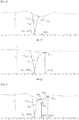
- Fig. 4 shows a differential thermal analysis chart (DTA chart) up to 300 to 500°C in differential thermal analysis under a heating condition of 10°C/min of the sulfide-based solid electrolyte of this embodiment.
- the endothermic peak (P 380 ) the peak point between the endothermic peak (P 380 ) and the endothermic peak (P 404 ) having a peak top at 404°C, and the start point of the peak on the low temperature side of the endothermic peak (P 380 ) are connected with a straight line (hereinafter this may be referred to as a "straight line 1"), and the heat quantity corresponding to the area surrounded by that straight line, and the tangent line at the inflection point of the endothermic peak on the low temperature side of the endothermic peak (P 380 ), and the tangent line at the inflection point of the endothermic peak on the high temperature side thereof is referred to as the heat quantity H 380 of the endothermic peak having a peak top at 380 ⁇ 15°C.
- the tangent line at the inflection point on the low temperature side of the endothermic peak and the tangent line at the inflection point on the high temperature side thereof are so employed that the difference between the area of the endothermic peak not allocated by the tangent lines and the area outside the endothermic peak counted by the tangent lines could be smaller.
- the total of the area surrounded by the line 1 of the endothermic peak (P 380 ) and the tangent line on the low temperature side, and the area surrounded by the line 1 of the endothermic peak (P 380 ) and the tangent line on the high temperature side corresponds to the "area of the endothermic peak not to be allocated", and the total of the area surrounded by the tangent line on the low temperature side, the tangent line on the high temperature side and the endothermic peak (P 380 ) corresponds to the "area outside the endothermic peak to be allocated”.
- an endothermic peak (P 413 ) having a peak top at 413°C appears, but since this peak is small, it is hidden by the endothermic peak (P 380 ) to show a shoulder not having a valley between peaks.
- the peak point (shoulder part) between the endothermic peak (P 380 ) and the endothermic peak (P 413 ) having a peak top at 413°C, and the start point of the peak on the low temperature side of the endothermic peak (P 380 ) are connected with a straight line, and the heat quantity corresponding to the area surrounded by that straight line, and the tangent line at the inflection point of the endothermic peak on the low temperature side of the endothermic peak (P 380 ), and the tangent line at the inflection point of the endothermic peak on the high temperature side thereof may be referred to as the heat quantity H 380 of the endothermic peak having a peak top at 380 ⁇ 15°C.
- the start point of the endothermic peak (P 380 ) is connected with the end point thereof via a straight line, and the heat quantity corresponding to the area surrounded by that straight line, the tangent line at the inflection point of the endothermic peak on the low temperature side of the endothermic peak (P 380 ) and the tangent line at the inflection point on the high temperature side thereof may be referred to as the heat quantity H 380 of the endothermic peak having a peak top at 380 ⁇ 15°C.
- the absolute value of the heat quantity H 380 of the endothermic peak having a peak top at 380 ⁇ 15°C need to be 10 (J/g) or more.
- the absolute value of the heat quantity H 380 is less than 10 (J/g), a high lithium ion conductivity could not be attained.
- the absolute value of the heat quantity H 380 is preferably 12 (J/g) or more, more preferably 15 (J/g) or more, even more preferably 20 (J/g) or more.
- the upper limit of the absolute value of the heat quantity H 380 is not specifically limited, but is generally 60 (J/g) or less, or 55 (J/g) or less, or 50 (J/g) or less.
- the ratio of the absolute value of the heat quantity H 380 of the endothermic peak, to the total H 350-450 of the absolute values of the heat quantities of the endothermic peaks each having a peak top at 350 to 450°C is preferably 50% or more.
- the proportion (H 380 /H 350-450 ) is 50% or more, a higher lithium ion conductivity can be attained.
- the proportion (H 380 /H 350-450 ) is preferably 60% or more, more preferably 70% or more, even more preferably 80% or more.
- the upper limit of the proportion (H 380 /H 350-450 ) is preferably higher, and from the viewpoint of attaining a higher lithium ion conductivity, the proportion is especially preferably 100%.
- the absolute value of the heat quantity H 380 of the endothermic peak in the proportion (H 380 /H 350-450 ) is a value determined according to the above-mentioned method.
- the total H 350-450 of the absolute values of the heat quantities of the endothermic peaks each having a peak top at 350 to 450°C is determined as follows.
- the total H 350-450 of the absolute values of the heat quantities of the endothermic peaks each having a peak top at 350 to 450°C in the proportion (H 380 /H 350-450 ) is the total of the absolute value of the heat quantity H 380 of the endothermic peak (P 380 ) having a peak top at 380 ⁇ 15°C, the absolute value of the heat quantity H 404 of the endothermic peak (P 404 ) having a peak top at 404°C, and the absolute value of the heat quantity H 422 of the endothermic peak (P 422 ) having a peak top at 422°C.
- the absolute value of the heat quantity H 380 of the endothermic peak (P 380 ) having a peak top at 380 ⁇ 15°C is 26.12 (J/g)
- the absolute value of the heat quantity H 404 of the endothermic peak (P 404 ) having a peak top at 404°C is 6.83 (J/g)
- the absolute value of the heat quantity H 422 of the endothermic peak (P 422 ) having a peak top at 422°C is 0.22 (J/g)
- the total H 350-450 of these heat quantities is 33.17 (J/g), that is, the proportion (H 380 /H 350-450 ) is calculated to be 78.7%.
- the absolute value of the heat quantity H 380 of the endothermic peak and the proportion (H 380 /H 350-450 ) may be controlled, for example, changing the kind of the halogen element in the alkali metal element, the sulfur element and the halogen element constituting the sulfide-based solid electrolyte, using any other elements than the phosphorus element and others, controlling the blending ratio of these elements, selecting the raw materials to be used in production, controlling the blending ratio of the raw materials and selecting the solvent to be used.
- the alkali metal element includes lithium (Li), sodium (Na), potassium (K), rubidium (Rb), and cesium (Cs), and in consideration of the fact that when an alkali metal having a smaller molecular weight, the ion conductivity of the resultant sulfide-based solid electrolyte tends to increase, lithium (Li) or sodium (Na) is preferred, and lithium (Li) is more preferred.
- One alone of these alkali metal elements may be used, or plural kinds thereof may be used in combination.
- a combination of lithium (Li) and sodium (Na) is preferred.
- single use of lithium (Li) is especially preferred.
- the halogen element includes fluorine (F), chlorine (Cl), bromine (Br) and iodine (I), and above all, chlorine (Cl), bromine (Br) and iodine (I) are preferred, and bromine (Br) and iodine (I) are more preferred, and one alone thereof may be used singly or plural kinds thereof may be used in combination.
- the absolute value of the heat quantity H 380 of the endothermic peak may be readily made to be 10 (J/g) or more, and the proportion (H 380 /H 350-450 ) may also be readily made to be 50% or more, that is, a sulfide-based solid electrolyte having a higher ion conductivity may be obtained.
- the proportion (H 380 /H 350-450 ) may also be readily made to be 50% or more, that is, a sulfide-based solid electrolyte having a higher ion conductivity may be obtained.
- bromine (Br) and iodine (I) is preferred.
- the sulfide-based solid electrolyte of this embodiment preferably contains a phosphorus element in addition to the alkali metal element, the sulfur element and the halogen element.
- the blending ratio of these elements is preferably (1.0 to 1.8)/(1.0 to 2.0)/(0.1 to 0.8)/(0.01 to 0.6), more preferably (1.1 to 1.7)/(1.2 to 1.8)/(0.2 to 0.6)/(0.05 to 0.5), even more preferably (1.2 to 1.6)/(1.3 to 1.7)/(0.25 to 0.5)/(0.08 to 0.4).
- the blending ratio (by mol) of the alkali metal element, the sulfur element, the phosphorus element, bromine and iodine is preferably (1.0 to 1.8)/(1.0 to 2.0)/(0.1 to 0.8)/(0.01 to 0.3)/(0.01 to 0.3), more preferably (1.1 to 1.7)/(1.2 to 1.8)/(0.2 to 0.6)/(0.05 to 0.25)/(0.05 to 0.25), even more preferably (1.2 to 1.6)/(1.3 to 1.7)/(0.25 to 0.5)/(0.07 to 0.2)/(0.07 to 0.2) and further more preferably (1.35 to 1.45)/(1.4 to 1.7)/(0.3 to 0.45)/(0.08 to 0.18)/(0.08 to 0.18).
- the absolute value of the heat quantity H 380 of the endothermic peak can be readily made to be 10 (J/g) or more, and the proportion (H 380 /H 350-450 ) can also be readily made to be 50% or more, that is, a solid electrolyte having a higher lithium ion conductivity can be obtained.
- the sulfide-based solid electrolyte of this embodiment may be any of an amorphous or crystalline one so far as it contains an alkali metal element, a phosphorus element and a halogen element and preferably further contains a sulfur element and has a specific exothermic peak in differential thermal analysis under a heating condition of 10°C/min.
- An amorphous sulfide-based solid electrolyte has a high ion conductivity and can provide souped-up batteries.
- the amorphous sulfide-based solid electrolyte of this embodiment contains an alkali metal element, a sulfur element, a phosphorus element and a halogen element, and typical examples thereof include a sulfide-based solid electrolyte formed of lithium sulfide, phosphorus sulfide and an alkali metal halide such as Li 2 S-P 2 S 5 -LiI, Li 2 S-P 2 S 5 -LiCl, Li 2 S-P 2 S 5 -LiBr, and Li 2 S-P 2 S 5 -LiI-LiBr; and a sulfide-based solid electrolyte further containing some other element such as an oxygen element and a silicon element, for example, Li 2 S-P 2 S 5 -Li 2 O-LiI, and Li 2 S-SiS 2 -P 2 S 5 -LiI.
- a sulfide-based solid electrolyte formed of lithium sulfide, phosphorus sulfide and an alkali metal halide such as Li 2 S-P 2 S 5 -LiI, Li 2 S-P 2 S 5 -LiCl, Li 2 S-P 2 S 5 -LiBr, and Li 2 S-P 2 S 5 -LiI-LiBr, is preferred.
- the kind of the element constituting the amorphous sulfide-based solid electrolyte can be identified, for example, using an ICP emission spectrometer.
- the molar ration of Li 2 S to P 2 S 5 is, from the viewpoint of providing a higher ion conductivity, preferably (65 to 85)/(15 to 35), more preferably (70 to 80)/(20 to 30), even more preferably (72 to 78)/(22 to 28).
- the sulfide-based solid electrolyte of this embodiment is, for example, Li 2 S-P 2 S 5 -LiI-LiBr
- the total content of lithium sulfide (Li 2 S) and diphosphorus pentasulfide (P 2 S 5 ) is preferably 60 to 100 mol%, more preferably 65 to 90 mol%, even more preferably 70 to 85 mol%.
- the ratio of lithium bromide (LiBr) to the total of lithium bromide (LiBr) and lithium iodide (LiI) is preferably 1 to 99 mol%, more preferably 20 to 90 mol%, even more preferably 40 to 80 mol%, and especially preferably 50 to 70 mol%.
- the shape of the amorphous sulfide-based solid electrolyte is not specifically limited, and is, for example, granular.
- the mean particle size (D 50 ) of the granular amorphous sulfide-based solid electrolyte is, for example, within a range of 0.01 ⁇ m to 500 ⁇ m, or 0.1 to 200 ⁇ m.
- the crystal structure of the crystalline sulfide-based solid electrolyte also includes an argyrodite-type crystal structure.
- the argyrodite-type crystal structure include an Li 7 PS 6 crystal structure; a crystal structure represented by a compositional formula Li 7-x P 1-y Si y S 6 or Li 7+x P 1-y Si y S 6 (x is -0.6 to 0.6, y is 0.1 to 0.6) which has a structure of Li 7 PS 6 and in which a part of P is substituted with Si; a crystal structure represented by Li 7-x-2y PS 6-x-y Cl x (0.8 ⁇ x ⁇ 1.7, 0 ⁇ y ⁇ -0.25x + 0.5); a crystal structure represented by Li 7-x PS 6-x Ha x (Ha represents Cl or Br, x is preferably 0.2 to 1.8).
- the crystal structure represented by a compositional formula Li 7-x P 1-y Si y S 6 or Li 7+x P 1-y Si y S 6 (x is -0.6 to 0.6, y is 0.1 to 0.6), which has the above-mentioned structure skeleton of Li 7 PS 6 and in which a part of P is substituted with Si, is a cubic crystal or a rhombic crystal, and is preferably a cubic crystal, and in X-ray diffractometry using a CuK ⁇ ray, the crystal structure gives peaks appearing mainly at 2 ⁇ 15.5°, 18.0°, 25.0°, 30.0°, 31.4°, 45.3°, 47.0°, and 52.0°.
- These peak positions may vary within a range of ⁇ 0.5°.
- the shape of the crystalline sulfide-based solid electrolyte is not specifically limited, and is, for example, granular.
- the mean particle size (D 50 ) of the granular crystalline sulfide-based solid electrolyte is, for example, within a range of 0.01 ⁇ m to 500 ⁇ m, or 0.1 to 200 ⁇ m.
- the sulfide-based solid electrolyte of this embodiment may be produced in any known method with no specific limitation thereto, so far as the resultant solid electrolyte contains a lithium element, a sulfur element, a phosphorus element and a halogen element and has a specific endothermic peak in differential heat analysis under a heating condition of 10°C/min, but in consideration of the fact that the resultant solid electrolyte could readily have the specific endothermic peak and could have a higher ion conductivity, it is desirable that the solid electrolyte is produced according to the production method for a sulfide-based solid electrolyte of this embodiment mentioned above, that is, according to the production method for a sulfide-based solid electrolyte where an alkali metal sulfide and a substance represented by the formula (1) are reacted in a solvent, or an alkali metal sulfide, a substance represented by the formula (1) and a phosphorus compound are reacted in a solvent: X
- the absolute value of the heat quantity H 380 of the endothermic peak and the proportion (H 380 /H 350-450 ) are controlled by controlling the condition of the raw materials to be used, the blending ratio thereof and the solvent to be used, as mentioned above.
- the raw materials to be used and the blending ratio thereof are the same as the raw materials and the blending ratio thereof described in the section of the production method for the sulfide-based solid electrolyte of this embodiment mentioned hereinabove.
- the solvent to be used may be the same as the solvent described for the production method of the sulfide-based solid electrolyte of this embodiment as above, and in consideration of attaining the specific endothermic peak with ease and attaining a higher ion conductivity, an aromatic hydrocarbon solvent or a solvent having an electrophilic group is preferred.
- an aromatic hydrocarbon solvent toluene, xylene, ethylbenzene and chlorobenzene are preferred, toluene and chlorobenzene are more preferred, and chlorobenzene is even more preferred.
- a solvent having an electrophilic group is preferred as facilitating the reaction of bromine (Br 2 ) with the other raw material.
- Preferred examples of the solvent having an electrophilic group include chlorobenzene, tert-butylbenzene, trifluoromethylbenzene, and nitrobenzene, and above all, chlorobenzene is preferred.
- the sulfide-based solid electrolyte of this embodiment has a high ion conductivity and has excellent battery performance, and is therefore favorably used for batteries. Use of a lithium element as the conductor species is especially preferred.
- the sulfide-based solid electrolyte of this embodiment may be used as a positive electrode layer or a negative electrode layer, or may also be used as an electrolyte layer. Each layer may be produced according to a known method.
- the battery has a collector in addition to the positive electrode layer, the electrolyte layer and the negative electrode layer, and the collector may be any known one.
- the collector may be any known one.
- a layer of Au, Pt, Al, Ti, or a layer formed by coating one reactive with the sulfide-based solid electrolyte, such as Cu, with Au or the like may be used.
- a planetary ball mill (trade name: Classic Line P-7, manufactured by Fritsch Japan Co., Ltd.) was set up. 0.598 g of lithium sulfide, 0.867 g of diphosphorus pentasulfide, 0.271 g of lithium bromide, and 0.264 g of iodine were weighed, put into a container (45 cc, made of zirconia) for the planetary ball mill, and further 4 g of dewatered toluene (water content: 10 ppm or less) was put thereinto, and the container was completely sealed up.
- This container was set in the planetary ball mill, and driven for simultaneous mixing, stirring and grinding at a table rotation number of 500 rpm for 40 hours to prepare a sulfide-based solid electrolyte.
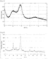
- the resultant, powdery amorphous sulfide-based solid electrolyte was analyzed through powdery X-ray diffraction (XRD) using an X-ray diffractometer (XRD) (Smart Lab Apparatus, manufactured by Rigaku Corporation). Any other peak than the peaks derived from the raw materials was detected.
- XRD X-ray diffractometer
- the resultant powdery amorphous sulfide-based solid electrolyte was heated on a hot plate set in a glove box, at 203°C for 3 hours.
- the heated powder was analyzed through powdery X-ray diffraction (XRD) using an X-ray diffractometer (XRD) (Smart Lab Apparatus, manufactured by Rigaku Corporation).
- XRD X-ray diffractometer
- Iodine (2 g) was added to 3 mL of a solvent, and stirred at room temperature (25°C) or 20 minutes. A solid iodine residue was confirmed visually.
- 0.1 g of the supernatant was weighed, and 1 g of an aqueous sodium thiosulfate solution (10% by mass, Na 2 S 2 O 3 ) was added to the supernatant, and shaken for about 1 minute to confirm disappearance of the color of the solution.
- the iodine concentration of the solution was quantified through ICP emission spectrometric analysis (high-frequency inductively-coupled plasma emission spectrometry) to calculate the solubility of iodine, which was 15.0% by mass.
- the resultant crystalline sulfide-based solid electrolyte was molded to give circular pellets each having a diameter of 10 mm (cross section S: 0.785 cm 2 ) and a height (L) of 0.1 to 0.3 cm to be samples. Electrode terminals were led from top and bottom of each sample to measure the ion conductivity of the sample according to an AC impedance method at 25°C (frequency range: 5 MHz to 0.5 Hz, amplitude: 10 mV) to draw a Cole-Cole plot.
- Example 1A The condition and the ion conductivity in Example 1A are shown in Table 1.
- a sulfide-based solid electrolyte was produced using the apparatus shown in Fig. 3 .
- the apparatus shown in Fig. 3 is described.
- the apparatus shown in Fig. 3 is provided with a bead mill 10 where raw materials are mixed, stirred and ground or processed through treatment of these as combined, and a reactor 20.
- the reactor 20 is provided with a container 22 and a stirrer 24, and the stirrer 24 is driven by a motor (M).
- the bead mill 10 is equipped with a heater 30 around the mill 10, in which hot water (HW) may run through, and the hot water (HW) supplies heat via the heater 30.
- the hot water (RHW) discharged out through the outlet of the heater 30 is, after heated, externally circulated into the heater 30 as hot water (HW).
- the reactor 20 is put in an oil bath 40.
- the oil bath 40 heats the raw materials and the solvent in the container 22 up to a predetermined temperature.
- a condenser pipe 26 for cooling and liquefying the vaporized solvent is attached to the reactor 20, and the cooling water (CW) cools the solvent in the condenser pipe 26.
- the cooling water (RCW) discharged out through the outlet of the condenser pipe 26 is, after cooled, externally circulated into the condenser pipe 26 as cooling water (CW).
- the bead mill 10 and the reactor 20 are connected via a first connecting pipe line 50 and a second connecting pipe line 52.
- the first connecting pipe line 50 transfers the raw materials and the solvent in the bead mill 10 toward the reactor 20, and the second connecting pipe line 52 transfers the raw materials and the solvent in the reactor 20 toward the bead mill 10. Since the raw materials and others are circulated via the connecting pipe lines 50 and 52, a pump 54 (for example, a diaphragm pump) is arranged in the second connecting pipe line 52.
- a thermometer (Th) is arranged in the reactor 20 and in the course of ejection from the pump 54 for constant temperature control.
- the peripheral speed of the bead mill was changed to 12 m/s, and hot water (HW) was applied thereto in a mode of external circulation, and the reaction was carried out in such a manner that the ejection temperature of the pump 54 could be kept at 70°C.
- HW hot water
- the residue was put on a hot plate, and dried thereon at 80°C to give a powdery amorphous sulfide-based solid electrolyte.
- the resultant sulfide-based solid electrolyte was analyzed through powdery X-ray diffractometry (XRD) in the same manner as in Example 1A, and any other peak than the peaks derived from the raw materials was not detected.
- the resultant, powdery amorphous sulfide-based solid electrolyte was heated at 195°C for 3 hours using a hot plate set in a glove box, thereby giving a crystalline sulfide-based solid electrolyte.
- XRD powdery X-ray diffractometry
- the ion conductivity of the resultant crystalline sulfide-based solid electrolyte was measured according to the above (for measurement of ion conductivity), and was 5.55 ⁇ 10 -3 (S/cm), which confirmed that the solid electrolyte has a high ion conductivity.
- the condition and the ion conductivity in Example 2A are shown in Table 1.
- Example 2A An amorphous sulfide-based solid electrolyte was produced in the same manner as in Example 2A, except that in Example 2A, 35.64 g of lithium sulfide, 49.25 g of diphosphorus pentasulfide, 14.06 g of iodine and 8.85 g of bromine were used.
- the resultant sulfide-based solid electrolyte was analyzed through powdery X-ray diffractometry in the same manner as in Example 1A, which confirmed absence of any other peak than the peaks derived from the raw materials.
- Example 3A The resultant amorphous sulfide-based solid electrolyte was heated at 203°C for 3 hours to give a crystalline sulfide-based solid electrolyte.
- XRD powdery X-ray diffractometry
- the ion conductivity of the resultant crystalline sulfide-based solid electrolyte was measured, and was 5.01 ⁇ 10 -3 (S/cm), which confirmed that the solid electrolyte has a high ion conductivity.
- the condition and the ion conductivity in Example 3A are shown in Table 1.
- a sulfide-based solid electrolyte was produced in the same manner as in Example 1A, except that in Example 1A, 0.645 g of lithium sulfide, 0.851 g of diphosphorus pentasulfide, 0.245 g of bromine, and 0.259 g of iodine were used, and the solvent was changed from dewatered toluene to dewatered ethylbenzene (water content: 10 ppm or less).
- Example 4A The resultant amorphous sulfide-based solid electrolyte was heated at 180°C for 3 hours to give a crystalline sulfide-based solid electrolyte.
- XRD powdery X-ray diffractometry
- the ion conductivity of the resultant crystalline sulfide-based solid electrolyte was measured, and was 5.27 ⁇ 10 -3 (S/cm), which confirmed that the solid electrolyte has a high ion conductivity.
- the condition and the ion conductivity in Example 4A are shown in Table 1.
- Example 4A An amorphous sulfide-based solid electrolyte was produced in the same manner as in Example 4A, except that in Example 4A, the solvent was changed from dewatered ethylbenzene to dewatered xylene (water content: 10 ppm or less).
- the resultant sulfide-based solid electrolyte was analyzed through powdery X-ray diffractometry (XRD) in the same manner as in Example 1A, which confirmed absence of any other peak than the peaks derived from the raw materials.
- XRD powdery X-ray diffractometry
- Example 5A The resultant amorphous sulfide-based solid electrolyte was heated at 188°C for 3 hours to give a crystalline sulfide-based solid electrolyte.
- XRD powdery X-ray diffractometry
- the ion conductivity of the resultant crystalline sulfide-based solid electrolyte was measured, and was 5.29 ⁇ 10 -3 (S/cm), which confirmed that the solid electrolyte has a high ion conductivity.
- the condition and the ion conductivity in Example 5A are shown in Table 1.
- Example 2A An amorphous sulfide-based solid electrolyte was produced in the same manner as in Example 2A, except that in Example 2A, 29.66 g of lithium sulfide and 47.83 g of diphosphorus pentasulfide were used, and in place of 13.97 g of iodine (Wako Pure Chemical Corporation, special grade) and 13.19 g of bromine (Wako Pure Chemical Corporation, special grade) dissolved in 200 ml of toluene, 14.95 g of lithium bromide, 15.36 g of lithium iodide and 1200 ml of dewatered toluene were put into the reactor 20.
- the resultant sulfide-based solid electrolyte was analyzed through powdery X-ray diffractometry (XRD) in the same manner as in Example 1A, in which any other peak than the peaks derived from the raw materials was not detected, and which confirmed that the product was an amorphous sulfide-based solid electrolyte.
- XRD powdery X-ray diffractometry
- amorphous sulfide-based solid electrolyte was heated at 203°C for 3 hours to give a crystalline sulfide-based solid electrolyte.
- XRD powdery X-ray diffractometry
- the ion conductivity of the resultant crystalline sulfide-based solid electrolyte was measured, and was 4.76 ⁇ 10 -3 (S/cm), which confirmed that the ion conductivity thereof was not so high like that of the ion conductivity of the crystalline sulfide-based solid electrolytes of Examples 1A to 5A.
- the condition and the ion conductivity in Comparative Example 1A are shown in Table 1.
- Example 2A An amorphous sulfide-based solid electrolyte was produced in the same manner as in Example 2A, except that in Example 2A, 31.58 g of lithium sulfide and 50.93 g of diphosphorus pentasulfide were used, and in place of 13.97 g of iodine (Wako Pure Chemical Corporation, special grade) and 13.19 g of bromine (Wako Pure Chemical Corporation, special grade) dissolved in 200 ml of toluene, 9.95 g of lithium bromide, 15.33 g of lithium iodide and 1200 ml of dewatered toluene were put into the reactor 20.
- the resultant sulfide-based solid electrolyte was analyzed through powdery X-ray diffractometry (XRD) in the same manner as in Example 1A, in which any other peak than the peaks derived from the raw materials was not detected, and which confirmed that the product was an amorphous sulfide-based solid electrolyte.
- XRD powdery X-ray diffractometry
- amorphous sulfide-based solid electrolyte was heated at 203°C for 3 hours to give a crystalline sulfide-based solid electrolyte.
- XRD powdery X-ray diffractometry
- the ion conductivity of the resultant crystalline sulfide-based solid electrolyte was measured, and was 4.36 ⁇ 10 -3 (S/cm), which confirmed that the ion conductivity thereof was not so high like that of the ion conductivity of the crystalline sulfide-based solid electrolytes of Examples 1A to 5A.
- the condition and the ion conductivity in Comparative Example 2A are shown in Table 1.
- Example 1 Grinding Machine Solvent Blending Ratio of Raw Materials (by mol)* 1 Halogen Halogen Lithium Sulfide Substance X 2 Ion Conductivity Compound 1 Compound 2 Molar Number Proportion * 2 Content * 3 S/cm
- Examples 1A to 5A confirmed that, according to the production method for a solid electrolyte of this embodiment, sulfide-based solid electrolytes having a high ion conductivity and excellent in battery performance can be obtained with ease. More specifically, comparison between Example 2A and Comparative Example 1A and comparison between Example 3A and Comparative Example 2A confirmed that, even when the same elements are used, the sulfide-based solid electrolytes produced according to the production method of this embodiment have a higher ion conductivity.
- the resultant, powdery amorphous sulfide-based solid electrolyte was heated at 203°C for 3 hours using a hot plate set in a glove box, thereby giving a crystalline sulfide-based solid electrolyte.
- XRD powdery X-ray diffractometry
- the ion conductivity of the resultant crystalline sulfide-based solid electrolyte was measured according to the above (for measurement of ion conductivity), and was 5.20 ⁇ 10 -3 (S/cm), which confirmed that the solid electrolyte has a high ion conductivity.
- amorphous sulfide-based solid electrolyte was subjected to differential thermal analysis (DTA) under a heating condition of 10°C/min from room temperature up to 500°C in a nitrogen gas atmosphere, using a differential thermal analyzer (DTA) (thermogravimetric analyzer "TGA/DSC1 (model number)", STAR e software, all manufactured by METTLER TOLEDO Corporation).
- DTA differential thermal analyzer
- TGA/DSC1 model number
- STAR e software all manufactured by METTLER TOLEDO Corporation
- an endothermic peak (P 380 ) having a peak top at 384°C at 380 ⁇ 15°C, an endothermic peak (P 406 ) having a peak top at 406°C, an endothermic peak (P 427 ) having a peak top at 427°C, and an endothermic peak (P 441 ) having a peak top at 441°C were detected, and the absolute value of the heat quantity at each endothermic peak is H 380 of 15.18(J/g), H 406 of 5.72(J/g), H 427 of 0.63(J/g), H 441 of 1.37(J/g), and the ratio (H 380 /H 350-450 ) is 66.3%.
- the condition, the heat quantity at each endothermic peak and the ion conductivity in Example 1B are shown in Table 2.
- the resultant sulfide-based solid electrolyte was analyzed through powdery X-ray diffractometry (XRD) in the same manner as in Example 1A, which confirmed absence of any other peak than the peaks derived from the raw materials.
- XRD powdery X-ray diffractometry
- the resultant, powdery amorphous sulfide-based solid electrolyte was heated at 188°C for 3 hours using a hot plate set in a glove box, thereby giving a crystalline sulfide-based solid electrolyte.
- XRD powdery X-ray diffractometry
- the ion conductivity of the resultant crystalline sulfide-based solid electrolyte was measured according to the above (for measurement of ion conductivity), and was 5.41 ⁇ 10 -3 (S/cm), which confirmed that the solid electrolyte has a high ion conductivity.
- amorphous sulfide-based solid electrolyte was subjected to differential thermal analysis (DTA) under a heating condition of 10°C/min from room temperature up to 500°C in a nitrogen gas atmosphere in the same manner as in Example 1B.
- Fig. 5 shows the differential thermal analysis chart (DTA chart). As in Fig.
- an endothermic peak (P 380 ) having a peak top at 387°C at 380 ⁇ 15°C, an endothermic peak (P 406 ) having a peak top at 404°C, and an endothermic peak (P 422 ) having a peak top at 422°C were detected, and the absolute value of the heat quantity at each endothermic peak is H 380 of 26.12(J/g), H 404 of 6.83(J/g), H 422 of 0.22(J/g), and the ratio (H 380 /H 350-450 ) is 78.7%.
- the condition, the heat quantity at each endothermic peak and the ion conductivity in Example 2B are shown in Table 2.
- a sulfide-based solid electrolyte was produced in the same manner as in Example 1B, except that in Example 1B, the solvent was changed from dewatered toluene to dewatered chlorobenzene (water content: 10 ppm or less). 20 ml of dewatered chlorobenzene was added to the resultant slurry product containing the sulfide-based solid electrolyte and the solvent, and collected in a 50-ml Schlenk bottle, and after powder precipitation, the supernatant solvent was removed.
- the resultant, powdery amorphous sulfide-based solid electrolyte was heated at 188°C for 3 hours using a hot plate set in a glove box, thereby giving a crystalline sulfide-based solid electrolyte.
- XRD powdery X-ray diffractometry
- the ion conductivity of the resultant crystalline sulfide-based solid electrolyte was measured according to the above (for measurement of ion conductivity), and was 5.74 ⁇ 10 -3 (S/cm), which confirmed that the solid electrolyte has a high ion conductivity.
- amorphous sulfide-based solid electrolyte was subjected to differential thermal analysis (DTA) under a heating condition of 10°C/min from room temperature up to 500°C in a nitrogen gas atmosphere in the same manner as in Example 1B.
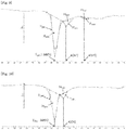
- Fig. 7 shows the differential thermal analysis chart (DTA chart). As in Fig.
- the resultant, powdery amorphous sulfide-based solid electrolyte was heated at 188°C for 3 hours using a hot plate set in a glove box, thereby giving a crystalline sulfide-based solid electrolyte.
- XRD powdery X-ray diffractometry
- the ion conductivity of the resultant crystalline sulfide-based solid electrolyte was measured according to the above (for measurement of ion conductivity), and was 6.09 ⁇ 10 -3 (S/cm), which confirmed that the solid electrolyte has a high ion conductivity.
- amorphous sulfide-based solid electrolyte was subjected to differential thermal analysis (DTA) under a heating condition of 10°C/min from room temperature up to 500°C in a nitrogen gas atmosphere in the same manner as in Example 1B.
- Fig. 8 shows the differential thermal analysis chart (DTA chart). As in Fig.
- the resultant sulfide-based solid electrolyte was analyzed through powdery X-ray diffractometry (XRD) in the same manner as in Example 1A, which confirmed absence of any other peak than the peaks derived from the raw materials.
- XRD powdery X-ray diffractometry
- the resultant, powdery amorphous sulfide-based solid electrolyte was heated at 195°C for 3 hours using a hot plate set in a glove box, thereby giving a crystalline sulfide-based solid electrolyte.
- XRD powdery X-ray diffractometry
- the ion conductivity of the resultant crystalline sulfide-based solid electrolyte was measured according to the above (for measurement of ion conductivity), and was 5.55 ⁇ 10 -3 (S/cm), which confirmed that the solid electrolyte has a high ion conductivity.
- amorphous sulfide-based solid electrolyte was subjected to differential thermal analysis (DTA) under a heating condition of 10°C/min from room temperature up to 500°C in a nitrogen gas atmosphere in the same manner as in Example 1B.
- Fig. 9 shows the differential thermal analysis chart (DTA chart). As in Fig.
- an endothermic peak (P 380 ) having a peak top at 386°C at 380 ⁇ 15°C, an endothermic peak (P 404 ) having a peak top at 404°C and an endothermic peak (P 434 ) having a peak top at 434°C were detected, and the absolute value of the heat quantity at each endothermic peak is H 380 of 33.72 (J/g), H 404 of 5.42 (J/g), and H 434 of 0.60 (J/g), and the ratio (H 380 /H 350-450 ) is 84.9%.
- the condition, the heat quantity at each endothermic peak and the ion conductivity in Example 5B are shown in Table 2.
- a sulfide-based solid electrolyte was produced in the same manner as in Example 5B, except that in Example 5B, the solvent was changed from dewatered toluene to dewatered chlorobenzene (water content: 10 ppm or less). 50 ml of the resultant slurry product containing the sulfide-based solid electrolyte and the solvent was collected in a 100-ml Schlenk bottle, and after powder precipitation, the supernatant solvent was removed.
- the resultant, powdery amorphous sulfide-based solid electrolyte was heated at 195°C for 3 hours using a hot plate set in a glove box, thereby giving a crystalline sulfide-based solid electrolyte.
- XRD powdery X-ray diffractometry
- the ion conductivity of the resultant crystalline sulfide-based solid electrolyte was measured according to the above (for measurement of ion conductivity), and was 5.57 ⁇ 10 -3 (S/cm), which confirmed that the solid electrolyte has a high ion conductivity.
- amorphous sulfide-based solid electrolyte was subjected to differential thermal analysis (DTA) under a heating condition of 10°C/min from room temperature up to 500°C in a nitrogen gas atmosphere in the same manner as in Example 1B.
- Fig. 10 shows the differential thermal analysis chart (DTA chart). As in Fig.
- the resultant sulfide-based solid electrolyte was analyzed through powdery X-ray diffractometry (XRD) in the same manner as in Example 1A, in which any other peak than the peaks derived from the raw materials was not detected, and which confirmed that the product was an amorphous sulfide-based solid electrolyte.
- XRD powdery X-ray diffractometry
- amorphous sulfide-based solid electrolyte was heated at 210°C for 3 hours to give a crystalline sulfide-based solid electrolyte.
- XRD powdery X-ray diffractometry
- the ion conductivity of the resultant crystalline sulfide-based solid electrolyte was measured, and was 5.04 ⁇ 10 -3 (S/cm), which confirmed that the ion conductivity thereof was not so high like that of the ion conductivity of the crystalline sulfide-based solid electrolytes of Examples 1B to 6B.
- the condition and the ion conductivity in Comparative Example 1B are shown in Table 2.
- amorphous sulfide-based solid electrolyte was subjected to differential thermal analysis (DTA) under a heating condition of 10°C/min from room temperature up to 500°C in a nitrogen gas atmosphere in the same manner as in Example 1B.
- Fig. 11 shows the differential thermal analysis chart (DTA chart). As in Fig.
- the absolute value of the heat quantity H 380 at the endothermic peak (P 380 ) having a peak top at 380 ⁇ 15°C is smaller than 10 (J/g), and the ratio (H 380 /H 350-450 ) is 17.5%.
- the condition, the heat quantity at each endothermic peak and the ion conductivity in Comparative Example 1B are shown in Table 2.
- the resultant sulfide-based solid electrolyte was analyzed through powdery X-ray diffractometry (XRD) in the same manner as in Example 1A, in which any other peak than the peaks derived from the raw materials was not detected, and which confirmed that the product was an amorphous sulfide-based solid electrolyte.
- XRD powdery X-ray diffractometry
- amorphous sulfide-based solid electrolyte was heated at 203°C for 3 hours to give a crystalline sulfide-based solid electrolyte.
- XRD powdery X-ray diffractometry
- the ion conductivity of the resultant crystalline sulfide-based solid electrolyte was measured, and was 4.76 ⁇ 10 -3 (S/cm), which confirmed that the ion conductivity thereof was not so high like that of the ion conductivity of the crystalline sulfide-based solid electrolytes of Examples 1B to 6B.
- the condition and the ion conductivity in Comparative Example 2B are shown in Table 1.
- amorphous sulfide-based solid electrolyte was subjected to differential thermal analysis (DTA) under a heating condition of 10°C/min from room temperature up to 500°C in a nitrogen gas atmosphere in the same manner as in Example 1B.
- Fig. 12 shows the differential thermal analysis chart (DTA chart). As in Fig.
- an endothermic peak (P 380 ) having a peak top at 384°C at 380 ⁇ 15°C, an endothermic peak (P 405 ) having a peak top at 405°C, an endothermic peak (P 423 ) having a peak top at 423°C, and an endothermic peak (P 435 ) having a peak top at 435°C were detected, and the absolute value of the heat quantity at each endothermic peak is H 380 of 7.64 (J/g), H 405 of 10.14 (J/g), H 423 of 0.27 (J/g), and H 435 of 0.93 (J/g).
- the absolute value of the heat quantity H 380 at the endothermic peak (P 380 ) having a peak top at 380 ⁇ 15°C is smaller than 10 (J/g), and the ratio (H 380 /H 350-450 ) is 40.3%.
- the condition, the heat quantity at each endothermic peak and the ion conductivity in Comparative Example 2B are shown in Table 2.
- the resultant sulfide-based solid electrolyte was analyzed through powdery X-ray diffractometry (XRD) in the same manner as in Example 1A, in which any other peak than the peaks derived from the raw materials was not detected.
- XRD powdery X-ray diffractometry
- amorphous sulfide-based solid electrolyte was heated at 198°C for 3 hours using a hot plate set in a glove box to give a crystalline sulfide-based solid electrolyte.
- XRD powdery X-ray diffractometry
- the ion conductivity of the resultant crystalline sulfide-based solid electrolyte was measured in the same manner as above (for measurement of ion conductivity), and was 5.16 ⁇ 10 -3 (S/cm), which confirmed that the ion conductivity thereof was not so high like that of the ion conductivity of the crystalline sulfide-based solid electrolytes of Examples 1B to 6B.
- the condition and the ion conductivity in Comparative Example 3B are shown in Table 2.
- amorphous sulfide-based solid electrolyte was subjected to differential thermal analysis (DTA) under a heating condition of 10°C/min from room temperature up to 500°C in a nitrogen gas atmosphere in the same manner as in Example 1B.
- Fig. 13 shows the differential thermal analysis chart (DTA chart). As in Fig.
- the absolute value of the heat quantity H 380 at the endothermic peak (P 380 ) having a peak top at 380 ⁇ 15°C is smaller than 10 (J/g), and the ratio (H 380 /H 350-450 ) is 4.7%.
- the condition, the heat quantity at each endothermic peak and the ion conductivity in Comparative Example 3B are shown in Table 2.
- a solid electrolyte having a high ion conductivity and excellent in battery performance can be produced not going through a step of removing water such as a drying step, while simplifying the production process and reducing the production cost.
- the solid electrolyte of this embodiment has a high ion conductivity and is excellent in battery performance.
- the solid electrolyte is favorably used for batteries, especially for batteries used in information-related equipments and communication instruments such as personal computers, video cameras, and mobile phones.
Landscapes
- Chemical & Material Sciences (AREA)
- Engineering & Computer Science (AREA)
- Chemical Kinetics & Catalysis (AREA)
- General Chemical & Material Sciences (AREA)
- Organic Chemistry (AREA)
- Materials Engineering (AREA)
- Life Sciences & Earth Sciences (AREA)
- Geochemistry & Mineralogy (AREA)
- Manufacturing & Machinery (AREA)
- Electrochemistry (AREA)
- Inorganic Chemistry (AREA)
- Ceramic Engineering (AREA)
- Dispersion Chemistry (AREA)
- Crystallography & Structural Chemistry (AREA)
- Physics & Mathematics (AREA)
- Condensed Matter Physics & Semiconductors (AREA)
- General Physics & Mathematics (AREA)
- Conductive Materials (AREA)
- Secondary Cells (AREA)
- Glass Compositions (AREA)
Abstract
Description
- The present invention relates to a solid electrolyte and a method for producing a solid electrolyte.
- In the field of all-solid batteries, heretofore, a sulfide-based solid electrolyte material has been known. For example,
PTL 1 reports producing a sulfide glass by reaction of lithium sulfide and phosphorus sulfide followed by heat-treating the sulfide glass to give a glass ceramic electrolyte having a high ion conductivity (for example, see PTL 1). However, a higher ion conductivity is desired, and it is reported to produce a sulfide glass by reaction of lithium halide, lithium sulfide and phosphorus sulfide and to heat-treat the sulfide glass to give a glass ceramic electrolyte having a high ion conductivity (for example, see PTL 2). - The lithium halide contained in these raw material compositions is produced using a raw material that is an aqueous solution in the production process, or is produced through reaction in water, and therefore the lithium halide is produced as a hydrate thereof (for example, see PTLs 3 to 6). When the lithium halide to be used as a raw material for a solid electrolyte contains water, the ion conductivity of the sulfide-based solid electrolyte may lower, and therefore, water must be removed from the lithium halide.
-
- PTL 1:
JP-2005-228570A - PTL 2:
JP-2013-201110A - PTL 3:
JP-2013-103851A - PTL 4:
JP-2013-256416A - PTL 5:
JP-2014-65637A - PTL 6:
JP-2014-65638A -
-
Fig. 1 is an X-ray analysis spectrum of the amorphous sulfide-based solid electrolyte obtained in Example 1A. -
Fig. 2 is an X-ray analysis spectrum of the crystalline sulfide-based solid electrolyte obtained in Example 1A. -
Fig. 3 is a schematic view of the apparatus used in Examples. -
Fig. 4 is a DTA chart up to 300 to 500°C in differential thermal analysis for explaining the absolute value of a heat quantity H380 of an endothermic peak. -
Fig. 5 is a DTA chart up to 300 to 500°C in differential thermal analysis for explaining the absolute value of a heat quantity H380 of an endothermic peak, which is a DTA chart of the solid electrolyte obtained in Example 2B. -
Fig. 6 is a DTA chart up to 300 to 500°C in differential thermal analysis of the solid electrolyte obtained in Example 1B. -
Fig. 7 is a DTA chart up to 300 to 500°C in differential thermal analysis of the solid electrolyte obtained in Example 3B. -
Fig. 8 is a DTA chart up to 300 to 500°C in differential thermal analysis of the solid electrolyte obtained in Example 4B. -
Fig. 9 is a DTA chart up to 300 to 500°C in differential thermal analysis of the solid electrolyte obtained in Example 5B. -
Fig. 10 is a DTA chart up to 300 to 500°C in differential thermal analysis of the solid electrolyte obtained in Example 6B. -
Fig. 11 is a DTA chart up to 300 to 500°C in differential thermal analysis of the solid electrolyte obtained in Comparative Example 1B. -
Fig. 12 is a DTA chart up to 300 to 500°C in differential thermal analysis of the solid electrolyte obtained in Comparative Example 2B. -
Fig. 13 is a DTA chart up to 300 to 500°C in differential thermal analysis of the solid electrolyte obtained in Comparative Example 3B. - If existing in a raw material for a solid electrolyte, water greatly lowers ion conductivity to cause a problem that an excellent solid electrolyte could not be obtained. On the other hand, a lithium halide to be the raw material is produced using water as a medium, heretofore as described in PTLs 3 to 6, and therefore in any case, a step of removing water is necessary. Specifically, water removal is carried out according to a method of baking at 300 to 440°C in an inert gas atmosphere or in vacuum (PTL 3), or drying in azeotropy with an organic solvent (PTL 4), or heating under reduced pressure (PTLs 5 and 6).
- However, water removal is not easy, and as described above, various ingenuities are necessary (PTLs 3 to 6). For example, when a drying step is carried out under reduced pressure with heating, the production process is complicated and large-scaled to cause a problem of time and money. In that manner, a solid electrolyte using a lithium halide as a raw material has advantages of high ion conductivity and excellent battery performance, but on the other hand, the energy for water removal is great and the production process is complicated and large-scaled to lead to higher costs, and as a result, the solid electrolyte is expensive.
- In particular, recently, with rapid popularization of information-related devices and communication devices and with technical advancement in performance thereof, more inexpensiveness and higher lithium ion conductivity have become desired. To satisfy these requirements, investigations from the aspect of production processes and investigations in other various aspects are being made.
- The present invention has been made in consideration of the situation as above, and an object thereof is to provide a sulfide-based solid electrolyte having a high ion conductivity and to provide a method for producing a sulfide-based solid electrolyte in which the production process is simplified.
- For solving the above-mentioned problems, the present inventors have assiduously studied and, as a result, have found that the problems can be solved by the following invention.
- [1] A method for producing a sulfide-based solid electrolyte, including causing a reaction of an alkali metal sulfide and a substance represented by the formula (1) in a solvent:

- [2] A method for producing a sulfide-based solid electrolyte, including causing a reaction of an alkali metal sulfide and a substance represented by the formula (1) and a phosphorus compound in a solvent:

- [3] A sulfide-based solid electrolyte containing an alkali metal element, a sulfur element and a halogen element, which is such that the absolute value of the heat quantity H380 of an endothermic peak that has a peak top at 380 ± 15°C, as measured in differential heat analysis under a heating condition of 10°C/min, is 10 (J/g) or more.
- According to the present invention, there can be provided a sulfide-based solid electrolyte having a high ion conductivity and a method for producing a sulfide-based solid electrolyte in which the production process is simplified.
- Embodiments of the present invention (which may be hereinafter referred to as "the present embodiments") are described below.
- The method for producing a sulfide-based solid electrolyte of this embodiment is a method for producing a sulfide-based solid electrolyte, including causing a reaction of an alkali metal sulfide and a substance represented by the formula (1) (which may be hereinafter referred to as "substance X2"):

- The sulfide-based solid electrolyte is a solid electrolyte having sulfur as an indispensable component, and means an electrolyte that maintains a solid form at 25°C in a nitrogen atmosphere.
- The sulfide-based solid electrolyte includes both an amorphous sulfide-based solid electrolyte and a crystalline sulfide-based solid electrolyte having a crystal structure. These sulfide-based solid electrolytes will be described in detail hereinunder.
- The sulfide-based solid electrolyte preferably contains sulfur and phosphorus, more preferably contains at least one selected from lithium and sodium, and sulfur and phosphorus, and even more preferably contains lithium, sulfur and phosphorus. Specifically, the sulfide-based solid electrolyte preferably has lithium ion conductivity and sodium ion conductivity.
- The alkali metal sulfide is preferably granular.
- Here, the mean particle size (D50) of the alkali metal sulfide particles is preferably 10 µm or more and 2,000 µm or less, more preferably 30 µm or more and 1500 µm or less, even more preferably 50 µm or more and 1,000 µm or less. In this description, the mean particle size (D50) means a particle size to reach 50% of all the particles as sequentially integrated from the particles having a smallest particle size on the particle size distribution cumulative curve drawn with particles, and the volumetric distribution is, for example, the mean particle size that can be measured using a laser diffraction/scattering particle size distribution measuring device.
- Preferred examples of the alkali metal sulfide for use in this embodiment include lithium sulfide (Li2S), sodium sulfide (Na2S), potassium sulfide (K2S), rubidium sulfide (Rb2S), and cesium sulfide (Cs2S). In consideration of the fact that when an alkali metal having a smaller molecular weight is used, the ion conductivity of the resultant sulfide-based solid electrolyte tends to increase, lithium sulfide (Li2S) and sodium sulfide (Na2S) are preferred, and lithium sulfide (Li2S) is more preferred.
- One alone of these alkali metal sulfides may be used singly or plural kinds thereof may be used in combination, and in the case where plural kinds are used as combined, a combination of lithium sulfide (Li2S) and sodium sulfide (Na2S) is preferred from the viewpoint of increasing ion conductivity. Sodium is an alkali metal whose atomic weight is larger than that of lithium, and therefore in consideration of the fact that, using a light alkali metal, the ion conductivity of the resultant sulfide-based solid electrolyte tends to increase, using lithium sulfide (Li2S) singly is especially preferred.
- Preferably, the alkali metal sulfide does not contain water, and the amount of water to be contained as an impurity is preferably 100 ppm by mass or less, more preferably 80 ppm by mass or less, even more preferably 50 ppm by mass or less, further more preferably 30 ppm by mass or less, and especially preferably 20 ppm by mass or less. The water content as above does not worsen the performance of the resultant sulfide-based solid electrolyte.
- The alkali metal sulfide usable in this embodiment is as described above, and an example of a method for producing lithium sulfide is described below.
- Lithium sulfide can be produced, for example, according to the method described in
JP-7-330312A JP-9-283156A JP-2010-163356A JP-9-278423A - Specifically, lithium hydroxide is reacted with hydrogen sulfide in a hydrocarbon-based organic solvent at 70°C to 300°C to give lithium hydrosulfide, and next, the reaction liquid is dehydrosulfurized to give lithium sulfide (
JP-2010-163356A JP-9-278423A - The substance X2 includes fluorine (F2), chlorine (Cl2), bromine (Br2), and iodine (I2), and above all, chlorine (Cl2), bromine (Br2), and iodine (I2) are preferred, and one alone or plural kinds thereof may be used either singly or as combined. Using the above as the substance X2 increases the probability of producing an electrolyte having a high ion conductivity. From the same viewpoint, the substance X2 is more preferably bromine (Br2), or iodine (I2).
- Since the substance X2 is used as a raw material, it is unnecessary to use an alkali metal halide as a raw material, and in particular, the step of removing water necessary in producing lithium bromide (LiBr) and lithium iodide (LiI) can be omitted, and accordingly, a high-performance solid electrolyte can be provided while the production process is simplified and the production cost is reduced.
- Preferably, the amount of water as an impurity in the substance X2 is small.
- In this embodiment, preferably, an alkali metal sulfide and a phosphorus compound and a substance X2 are reacted.
- Preferred examples of the phosphorus compound include phosphorus sulfides such as diphosphorus trisulfide (P2S3), and diphosphorus pentasulfide (P2S5); and phosphate compounds such as sodium phosphate (Na3PO4), and lithium phosphate (Li3PO4). Above all, phosphorus sulfides are preferred, and diphosphorus pentasulfide (P2S5) is more preferred. The phosphorus compound may include an elemental phosphorus. The phosphorus compounds such as diphosphorus pentasulfide (P2S5) that are industrially produced and sold are readily available. These phosphorus compounds may be used alone or plural kinds thereof may be used in combination.
- In this embodiment, so far as the above-mentioned alkali metal sulfide and the substance X2, preferably the alkali metal sulfide, the phosphorus compound and the substance X2 are used, any other raw materials than the above may also be contained.
- For example, using a sodium halide such as sodium iodide (NaI), sodium fluoride (NaF), sodium chloride (NaCl) or sodium bromide (NaBr), or a lithium compound such as lithium oxide (Li2O), or lithium carbonate (Li2CO3), an alkali metal element (lithium (Li)) may be supplied.
- Using a metal sulfide such as silicon sulfide (SiS2), germanium sulfide (GeS2), boron sulfide (B2S3), gallium sulfide (Ga2S3), tin sulfide (SnS or SnS2), aluminum sulfide (Al2S3), or zinc sulfide (ZnS), a sulfur atom may be supplied.
- Using phosphorus halides such as various phosphorus fluorides (PF3, PF5), various phosphorus chlorides (PCl3, PCl5, P2Cl4), phosphorus oxychloride (POCl3), various phosphorus bromides (PBr3, PBr5), phosphorus oxybromide (POBr3), and various phosphorus iodides (PI3, P2I4), a phosphorus element and a halogen element may be supplied at the same time. In addition, using a thiophosphoryl halide such as thiophosphoryl fluoride (PSF3), thiophosphoryl chloride (PSCl3), thiophosphoryl bromide (PSBr3), thiophosphoryl iodide (PSI3), thiophosphoryl dichlorofluoride (PSCl2S), or thiophosphoryl dibromofluoride (PSBr2F), a phosphorus element, a sulfur element and a halogen element may be supplied at the same time.
- Using a metal halide such as an aluminum halide, a silicon halide, a germanium halide, an arsenic halide, a selenium halide, a tin halide, an antimony halide, a tellurium halide or a bismuth halide, a halogen element may be supplied.
- In addition, for example, within a range not detracting from the advantageous effects of the present invention, a lithium halide such as lithium fluoride (LiF), lithium chloride (LiCl), lithium bromide (LiBr) or lithium iodide (LiI) may be used to supply a lithium element and a halogen element.
- In the production method of this embodiment, a solid electrolyte containing an alkali metal element, a phosphorus element and a sulfur element may be used as a raw material. Examples of such a solid electrolyte include Li2S-P2S5, Li2S-P2S5-LiI, Li2S-P2S5-LiCl, Li2S-P2S5-LiBr, Li2S-P2S5-Li2O, Li2S-P2S5-Li2O-LiI, Li2S-SiS2- P2S5- LiI, and Li2S-P2S5-ZmSn (where m and n each represent a positive number, and Z is any of Si, Ge, Zn, Ga, Sn or Al). As known from these exemplifications, a solid electrolyte containing a halogen element, an oxygen element and any other element may be used as a raw material so far as it contains an alkali metal element, a phosphorus element and a sulfur element.
- For example, in the case where Li2S-P2S5 is used as a raw material, at least any one of iodine (I2) and bromine (Br2) may be supplied as an elemental halogen. In this case, iodine (I2) alone may be supplied as an elemental halogen and lithium bromide (LiBr) may be used as a supply source a bromine element, or a raw material containing any other halogen atom may also be used. Depending on the solid electrolyte to be used as a raw material and on the intended solid electrolyte, any ones may be appropriately selected from those exemplified above and may be used as raw materials.
- Among the above, also in the case where a solid electrolyte not having a halogen atom such as Li2S-P2S5-Li2O or Li2S-P2S5-ZmSn is used as a raw material, a solid electrolyte containing a halogen atom may be produced in the same manner as that using Li2S-P2S5.
- In addition, for example, in the case where Li2S-P2S5-LiBr is used as a raw material, a solid electrolyte containing an iodine element may be produced using iodine (I2) as an elemental halogen.
- The proportion of each raw material in all raw materials is not specifically limited, and for example, in the case where lithium sulfide (Li2S) and diphosphorus pentasulfide (P2S5) are used as raw materials, the ratio of the molar number of lithium sulfide (Li2S) excluding the same molar number of lithium sulfide (Li2S) as the molar number of the substance X2, relative to the total molar number of lithium sulfide (Li2S) and diphosphorus pentasulfide (P2S5) excluding the same molar number of lithium sulfide (Li2S) as the molar number of the substance X2 is preferably within a range of 60 to 90%, more preferably within a range of 65 to 85%, even more preferably within a range of 68 to 82%, still more preferably within a range of 72 to 78%, and especially preferably within a range of 73 to 77%. This is because, falling within the range of such proportion, a sulfide-based solid electrolyte having a high ion conductivity can be obtained.
- In the case where an alkali metal sulfide, a phosphorus compound and a substance X2 are used as raw materials, the content of the substance X2 relative to the total amount of the alkali metal sulfide, the phosphorus compound and the substance X2 is preferably 1 to 50 mol%, more preferably 2 to 40 mol%, even more preferably 3 to 25 mol%, and still more preferably 3 to 15 mol%.
- In the case where an alkali metal sulfide, a phosphorus compound, a substance X2, and a lithium halide are used as raw materials, the content (α mol%) of the substance X2 and the content (β mol%) of the lithium halide relative to the total amount of these preferably satisfy the following expression (2), more preferably satisfy the following expression (3), even more preferably satisfy the following expression (4), and further more preferably satisfy the following expression (5).




- In the case where two kinds of halogen elements are contained in the raw material and where the molar number of one halogen atom in the raw material is represented by A1 and the molar number of the other halogen atom therein is represented by A2, preferably A1/A2 is (1 to 99)/(99 to 1), more preferably 10/90 to 90/10, even more preferably 20/80 to 80/20, and further more preferably 30/70 to 70/30.
- In the case where a bromine element and an iodine element are contained as halogen atoms in the raw material and where the molar number of the bromine element in the raw material is represented by B1 and the molar number of the iodine element in the raw material is represented by B2, preferably B1/B2 is (1 to 99)/(99 to 1), more preferably 15/85 to 90/10, even more preferably 20/80 to 80/20, further more preferably 30/70 to 75/25, and especially preferably 35/65 to 75/25.
- The solvent for use in this embodiment is preferably one in which the solubility of the substance X2 is 0.01% by mass or more.
- As described above, in the production method of this embodiment, a substance X2 is used as a raw material in place of a lithium halide such as lithium iodide (LiI) heretofore used for producing a high-performance solid electrolyte therefore evading water removal in the production process for the lithium halide, and consequently a high-performance solid electrolyte can be provided while the production process is simplified and the production cost is reduced. On the other hand, the substance X2 has a property of locally fracturing a passive-state coating film to accelerate local corrosion, especially crevice corrosion, and therefore, when the substance X2 is kept in direct contact with a production device, it would accelerate corrosion of the production device.
- In the production method of this embodiment, a solvent in which the solubility of the substance X2 is 0.01% by mass or more is used, and therefore the raw materials can be reacted more smoothly and the risk of direct contact between the substance X2 and a production device can be reduced to more readily prevent corrosion of the production device. In addition, the substance X2 dissolves in the solvent and therefore the unreacted substance X2 can be readily removed from the sulfide-based solid electrolyte, and consequently, a sulfide-based solid electrolyte where the substance X2 does not exist as an impurity or may exist little can be obtained.
- From the same viewpoint as above, the solubility of the substance X2 is preferably 0.03% by mass or more, more preferably 0.05% by mass or more, even more preferably 0.1% by mass or more. The upper limit is not specifically limited, and for example, the solubility may be 60% by mass or less, or 55% by mass or less, or 10% by mass or less.
- The solubility of the substance X2 is a value measured according to the following measurement method.
- A substance X2 (2 g) is dissolved in 3 mL of a solvent, and stirred at room temperature (25°C) for 20 minutes. 0.1 g of the supernatant is weighed, 1 g of an aqueous sodium thiosulfate solution (10% by mass, Na2S2O3) is added to the supernatant and shaken for about 1 minute to confirm disappearance of the color of the solution. The iodine concentration of the solution is quantified through ICP emission spectrometric analysis (high-frequency inductively-coupled plasma emission spectrometry) to calculate the solubility of the substance X2.
- The solvent is preferably one capable of readily dissolving sulfur, for example, a solvent having a sulfur solubility of 0.01% by mass or more. The sulfur solubility in the solvent is more preferably 0.03% by mass or more, even more preferably 0.05% by mass or more, especially preferably 0.1% by mass or more, and the upper limit of the sulfur solubility is not specifically limited. For example, the solubility may be 60% by mass or less, 55% by mass or less or 10% by mass or less.
- Here, the sulfur solubility is a value measured as follows.
- 50 mL of a solvent is added to 10 g of sulfur, conditioned at 25°C in an oil bath, and stirred for 2 hours. Subsequently, the supernatant was separated using a cannula (transport pipe) equipped with a glass filter. The separated supernatant was vacuumed to give dry sulfur. From the mass of the dry sulfur and the mass of the solvent in which the dry sulfur dissolved, the sulfur solubility (% by mass) is calculated.
- In the production method of this embodiment, as described above, a substance X2 (for example, iodine (I2), bromine (Br2)) is used as a raw material in place of the lithium halide such as lithium iodide (LiI) or lithium bromide (LiBr) heretofore used for producing a high-performance solid electrolyte therefore evading water removal in the production process for the lithium halide, and consequently a high-performance solid electrolyte can be provided while the production process is simplified and the production cost is reduced. Consequently, the alkali metal component that has heretofore been supplied as a lithium halide must be supplied as an alkali metal sulfide, and as a result, sulfur may form as a side product.
- In the production method of this embodiment, preferably, a solvent having a sulfur solubility of 0.01% by mass or more is used, and therefore the raw materials can be reacted more smoothly and any excessive sulfur component, if generated, can be removed, consequently enhancing the production efficiency. In addition, sulfur dissolves in the solvent, and therefore the unreacted sulfur can be readily removed from the sulfide-based solid electrolyte, and a sulfide-based solid electrolyte not containing sulfur as an impurity or containing little sulfur can be provided.
- The solvent is preferably one hardly dissolving an alkali metal sulfide, for example, a solvent having an alkali metal sulfide solubility of 1% by mass or less. Using such a solvent, the amount of dissolution of an alkali metal sulfide in the solvent can be reduced, and consequently, the alkali metal sulfide can be consumed more efficiently for the reaction with the substance X2. The solubility of the alkali metal sulfide is more preferably 0.5% by mass or less, even more preferably 0.1% by mass or less, and further more preferably 0.07% by mass or less. The lower limit of the alkali metal sulfide solubility is not limited.
- Preferred examples of such a solvent include hydrocarbon solvents such as aliphatic hydrocarbon solvents, alicyclic hydrocarbon solvents, and aromatic hydrocarbon solvents; and carbon atom-containing solvents such as solvents containing a carbon atom and a hetero atom.
- Examples of the aliphatic hydrocarbon solvent include hexane, pentane, 2-ethylhexane, heptane, octane, decane, undecane, dodecane, and tridecene; examples of the alicyclic hydrocarbon solvent include cyclohexane, and methylcyclohexane; examples of the aromatic hydrocarbon solvent include benzene, toluene, xylene, mesitylene, ethylbenzene, tert-butylbenzene, chlorobenzene, trifluoromethylbenzene, and nitrobenzene; and examples of the solvent containing a carbon atom and a hetero atom include carbon disulfide, diethyl ether, dibutyl ether, and tetrahydrofuran.
- Among these, hydrocarbon solvents are preferred, aromatic hydrocarbon solvents are more preferred, toluene, xylene and ethylbenzene are even more preferred, and toluene is especially preferred. Water is unfavorable as a solvent as it may worsen the performance of the solid electrolyte.
- In the case where bromine (Br2) is used as the substance X2, from the viewpoint of efficiently attaining the reaction between the bromine (Br2) and the other raw material, especially among saturated aliphatic hydrocarbon solvents, saturated alicyclic hydrocarbon solvents and aromatic hydrocarbon solvent, those substituted with an electrophilic group, for example, tert-butylbenzene, trifluoromethylbenzene and nitrobenzene are preferably used.
- The amount of the solvent to be used is preferably such that the total amount of the raw materials could be 0.1 to 1 kg in 1 liter of the solvent, more preferably 0.05 to 0.8 kg, even more preferably 0.2 to 0.7 kg. When the amount of the solvent used falls within the above range, the raw materials can be slurry and can be more smoothly reacted, and in addition, solvent removal, if needed, can be attained with ease.
- When the raw materials of an alkali metal sulfide and a substance X2 are reacted in the production method for a sulfide-based solid electrolyte of this embodiment, for example, these raw materials may be mixed, stirred or ground or may be processed through any of these treatments as combined, for the purpose of increasing the reaction speed to thereby efficiently produce a sulfide-based solid electrolyte.
- The mixing method is not specifically limited. For example, raw materials and optionally a solvent may be put into a production device where the solvent and the raw materials can be mixed, and mixed therein. The production device is not specifically limited so far as raw materials and a solvent can be mixed therein, and for example, a medium-assisted grinding machine may be used.
- The medium-assisted grinding machine may be roughly grouped into a container-driven grinding machine and a medium-stirring grinding machine. The container-driven grinding machine includes a stirring tank, a grinding tank, and a ball mill and a bead mill including these as combined (for example, one having a configuration as shown in
Fig. 3 , as used in Examples). The medium-stirring grinding machine includes various types of grinding machines of an impact grinding machine such as as a cutter mill, a hammer mill and a pin mill; a tower-type grinding machine such as a tower mill; a stirring tank grinding machine such as an attritor, an aquamizer, and a sand grinder; a fluid tank grinding machine such as a viscomill, and a pear mill; a fluid tube grinding machine; an annular type grinding machine such as a co-ball mill; a continuous dynamic grinding machine; and a monoaxial or multiaxial kneading machine. - These grinding machines may be appropriately selected depending on the intended size thereof, and for a relatively small-size system, a container-driven grinding machine such as a ball mill or a bead mill may be used, while for large-scale or industrial-scale mass production, the other types of grinding machines are preferably used.
- When these grinding machines are used, raw materials and a solvent and also grinding media are put thereinto, and then the machine is driven to attain mixing, stirring and grinding therein. Here, raw materials, a solvent and grinding media are put into the machine, but the order of putting them thereinto is not limited.
- In the production method for a sulfide-based solid electrolyte of this embodiment, raw material and a solvent are mixed, and therefore the raw materials can be brought into contact more readily to promote the reaction therebetween to give a sulfide-based solid electrolyte. From the viewpoint of promoting the contact between raw materials to give efficiently a sulfide-based solid electrolyte, it is desirable that a solvent and raw materials are mixed, and further stirred and ground, or processed for treatment of stirring and grinding. From the viewpoint of promoting the contact between raw materials, in particular, a treatment including grinding, namely a treatment of grinding, or stirring and grinding is preferably carried out. In the treatment of grinding, the surfaces of the raw materials may be cut off to make new surfaces thereof exposed out, and as a result, the new surfaces may be brought into contact with the surfaces of the other raw material to further promote the reaction between the raw materials to efficiently produce a sulfide-based solid electrolyte.
- For example, a device of a ball mill or a bead mill is described as an example. In these mills, the grain size of the media therein such as balls or beads (balls generally have a size of φ2 to 20 mm or so, and beads generally have a size of φ0.02 to 2 mm or so, the material thereof (for example, metals such as stainless, chrome steel, or tungsten carbide; ceramics such as zirconia or silicon nitride; minerals such as agate), the rotation number of the rotor and the time may be selected to attain mixing, stirring or grinding, or a combined treatment thereof, and the particle size of the resultant sulfide-based solid electrolyte can be controlled.
- In this embodiment, these conditions are not specifically limited. For example, using a ball mill, especially a planetary ball mill, and using balls of ceramics, above all zirconia balls having a size of φ1 to 10 mm, raw materials may be stirred and ground at a rotor rotation number of 300 to 1,000 rpm for 0.5 to 100 hours.
- The temperature in mixing, stirring and grinding is not specifically limited, and may be, for example, 20 to 80°C.
- In this embodiment, after raw materials and a solvent have been mixed, raw materials may be further added thereto and mixed, and this operation may be repeated twice or more.
- In the case where raw materials and a solvent are mixed and stirred, additional raw materials may be further added and mixed during mixing and stirring them and/or after that, and this operation may be repeated twice or more. For example, raw materials and a solvent are put into a ball mill or a bead mill, and mixed and stirred therein, and during the mixing and stirring, additional raw materials may be further put into the container, and after mixing and stirring them (after the mixing and stirring is once stopped), raw materials may be put into the container, and mixing and stirring them may be restarted, or during mixing and stirring, and after that, additional raw materials may be put into the container.
- Also in the case where raw materials and solvent are mixed and ground, or stirred and ground, additional raw materials may be further added like in the above-mentioned case of stirring.
- In that manner, by further adding raw materials, the frequency of optional treatment of solvent removal or the like may be reduced, and accordingly, a sulfide-based solid electrolyte can be produced more efficiently.
- In the case where additional raw materials are further added, if desired, a solvent may also be added, but the solvent will have to be removed in obtaining the intended sulfide-based solid electrolyte, the amount of the solvent to be additionally added is preferably minimized.
- Thus produced, the solid electrolyte contains a solvent. Consequently, in the production method for a solid electrolyte of this embodiment, preferably, the solvent is removed. By removing the solvent, the side product sulfur may also be removed.
- The solvent removal may be carried out according to a method where the solvent-containing solid electrolyte is once transferred to a container, and after the solid electrolyte has deposited therein, the supernatant solvent is removed.
- The solvent may be removed by drying, which may be combined with removal of the supernatant solvent. In this case, for example, the precipitated solid electrolyte is put on a heating device such as a hot plate, and then heated thereon at 50 to 90°C to vaporize the solvent for solvent removal.
- Depending on the solvent, reduced-pressure drying may be carried out using a vacuum pump or the like at a temperature of 90 to 110°C or so. For example, this is effective for the case where an aromatic hydrocarbon solvent such as xylene, ethylbenzene or chlorobenzene is used.
- The solvent to be used in this embodiment is one capable of dissolving the substance X2, namely, the solubility of the substance X2 therein is 0.01% by mass or more. Accordingly, an unreacted substance X2 can be readily removed from the sulfide-based solid electrolyte, and the embodiment using the solvent is advantageous in that a sulfide-based solid electrolyte not containing or containing little amount of the substance X2 as an impurity can be obtained.
- The resultant sulfide-based solid electrolyte is an amorphous sulfide-based solid electrolyte containing at least an alkali metal element, a sulfur element and a halogen element, preferably containing an alkali metal element, a sulfur element, a phosphorus element and a halogen element. In this description, the amorphous sulfide-based solid electrolyte means that the X-ray diffraction pattern thereof in X-ray diffractometry is a halo pattern not substantially showing any other peak than the materials-derived peaks, irrespective of the presence or absence of peaks derived from the raw materials of the solid electrolyte.
- The amorphous sulfide-based solid electrolyte has a high ion conductivity and can increase battery output.
- Typical examples of the amorphous sulfide-based solid electrolyte include Li2S-P2S5-LiI, Li2S-P2S5-LiCl, Li2S-P2S5-LiBr, Li2S-P2S5-LiI-LiBr, Li2S-P2S5-Li2O-LiI, and Li2S-SiS2-P2S5-LiI. The kind of the element constituting the amorphous sulfide-based solid electrolyte can be identified, for example, using an ICP emission spectrometric apparatus.
- The shape of the amorphous sulfide-based solid electrolyte is not specifically limited, and is, for example, granular. The mean particle size (D50) of the granular amorphous sulfide-based solid electrolyte is, for example, within a range of 0.01 µm to 500 µm, or 0.1 to 200 µm.
- The production method for the solid electrolyte of this embodiment may further include heating. By further heating, the amorphous solid electrolyte may be converted into a crystalline solid electrolyte.
- The heating temperature may be appropriately selected depending on the structure of the amorphous solid electrolyte, and may be, for example, within a range of the peak top, as a starting point, of the endothermic peak observed on the lowest temperature side in differential thermal analysis of the amorphous solid electrolyte under a heating rate of 10°C/min, preferably ± 40°C, more preferably ± 30°C, even more preferably ± 20°C.
- More specifically, the heating temperature is preferably 150°C or higher, more preferably 170°C or higher, even more preferably 190°C or higher. On the other hand, the upper limit of the heating temperature is not specifically limited, and is preferably 300°C or lower, more preferably 280°C or lower, even more preferably 250°C or lower.
- The heating time is not specifically limited so far as a desired crystalline solid electrolyte can be produced within the time, and is, for example, preferably 1 minute or more, more preferably 10 minutes or more, even more preferably 30 minutes or more, and the upper limit of the heating time is not specifically limited, and is preferably 24 hours or less, more preferably 10 hours or less, even more preferably 5 hours or less.
- Preferably, the heating is carried out in an inert gas atmosphere (for example, nitrogen atmosphere, argon atmosphere), or a reduced-pressure atmosphere (especially in vacuum). This is because the crystalline solid electrolyte can be prevented from being degraded (for example, oxidized). The heating method is not specifically limited, and for example, a method of using a vacuum heating apparatus, an argon gas atmosphere furnace or a baking furnace may be employed. Industrially, a horizontal drying machine, a horizontal shaking flow drying machine or the like having a heating means and a feeding mechanism may also be employed.
- As described above, a crystalline sulfide-based solid electrolyte can be obtained by heating an amorphous sulfide-based solid electrolyte. The crystalline sulfide-based solid electrolyte is a sulfide-based solid electrolyte whose X-ray diffraction pattern in X-ray diffractometry shows peaks derived from the sulfide-based solid electrolyte, irrespective of the presence or absence of peaks derived from the raw materials for the sulfide-based solid electrolyte therein. Specifically, the crystalline sulfide-based solid electrolyte contains a crystal structure derived from the sulfide-based solid electrolyte, and a part thereof may be a crystal structure derived from the sulfide-based solid electrolyte or all thereof may be a crystal structure derived from the sulfide-based solid electrolyte. With that, the crystalline sulfide-based solid electrolyte may contain, as a part thereof, an amorphous sulfide-based solid electrolyte so far as it has the X-ray diffraction pattern as mentioned above.
- More specifically, examples of the crystal structure of the crystalline solid electrolyte include an Li3PS4 crystal structure, an Li4P2S6 crystal structure, an Li7PS6 crystal structure, and a crystal structure having peaks at around 2θ = 20.2° and 23.6° (for example,
JP-2013-16423A - Here, the crystal structure having peaks at around 2θ = 20.2° and 23.6° is preferred. For example, it is a crystal structure having peaks at 2θ = 20.2° ± 0.3° and 23.6° ± 0.3°.
- The shape of the crystalline sulfide-based solid electrolyte is not specifically limited, and is, for example, granular. The mean particle size (D50) of the granular crystalline sulfide-based solid electrolyte is, for example, within a range of 0.01 µm to 500 µm, or 0.1 to 200 µm.
- The sulfide-based solid electrolyte obtained according to the production method of this embodiment has a high ion conductivity and excellent battery performance and is favorably used for batteries. Use of a lithium element as the conductor species is especially preferred. The sulfide-based solid electrolyte obtained according to the production method of this embodiment may be used as a positive electrode layer or a negative electrode layer, or may also be used as an electrolyte layer. Each layer may be produced according to a known method.
- Preferably, the battery has a collector in addition to the positive electrode layer, the electrolyte layer and the negative electrode layer, and the collector may be any known one. For example, a layer of Au, Pt, Al, Ti, or a layer formed by coating one reactive with the sulfide-based solid electrolyte, such as Cu, with Au or the like may be used.
- The sulfide-based solid electrolyte of this embodiment contains an alkali metal element, a sulfur element and a halogen element, and is such that the absolute value of the heat quantity H380 of an endothermic peak that has a peak top at 380 ± 15°C, as measured in differential heat analysis under a heating condition of 10°C/min, is 10 (J/g) or more. The present inventors have found that when the heat quantity of the endothermic peak expressing within a specific temperature range of 380 ± 15°C is larger, a higher ion conductivity tends to be attained. In addition, the inventors have further found that a solid electrolyte having such a characteristic can be obtained with ease according to the production method of this embodiment.
- In this embodiment, the endothermic peak heat quantity is a heat quantity corresponding to the area of an endothermic peak measured in differential thermal analysis under a heating condition of 10°C/min. Hereinunder a method for determining the endothermic peak heat quantity is described more specifically.
-
Fig. 4 shows a differential thermal analysis chart (DTA chart) up to 300 to 500°C in differential thermal analysis under a heating condition of 10°C/min of the sulfide-based solid electrolyte of this embodiment. The DTA chart shown in (4-1) ofFig. 4 is a chart of the sulfide-based solid electrolyte of Example 2B to be mentioned below, and in this chart, the endothermic peak (P380) having a peak top at T380 = 387°C corresponds to the "endothermic peak having a peak top at 380 ± 15°C". In this embodiment, regarding the endothermic peak (P380), the peak point between the endothermic peak (P380) and the endothermic peak (P404) having a peak top at 404°C, and the start point of the peak on the low temperature side of the endothermic peak (P380) are connected with a straight line (hereinafter this may be referred to as a "straight line 1"), and the heat quantity corresponding to the area surrounded by that straight line, and the tangent line at the inflection point of the endothermic peak on the low temperature side of the endothermic peak (P380), and the tangent line at the inflection point of the endothermic peak on the high temperature side thereof is referred to as the heat quantity H380 of the endothermic peak having a peak top at 380 ± 15°C. Here, the tangent line at the inflection point on the low temperature side of the endothermic peak and the tangent line at the inflection point on the high temperature side thereof are so employed that the difference between the area of the endothermic peak not allocated by the tangent lines and the area outside the endothermic peak counted by the tangent lines could be smaller. For example, in (4-1) ofFig. 4 , the total of the area surrounded by theline 1 of the endothermic peak (P380) and the tangent line on the low temperature side, and the area surrounded by theline 1 of the endothermic peak (P380) and the tangent line on the high temperature side corresponds to the "area of the endothermic peak not to be allocated", and the total of the area surrounded by the tangent line on the low temperature side, the tangent line on the high temperature side and the endothermic peak (P380) corresponds to the "area outside the endothermic peak to be allocated". - The DTA chart shown in (4-2) of
Fig. 4 is a chart of the sulfide-based solid electrolyte of Example 4B to be mentioned below, and in this chart, the endothermic peak (P380) having a peak top at T380 = 386°C corresponds to the "endothermic peak having a peak top at 380 ± 15°C" (P380). In the case of (4-2) ofFig. 4 , an endothermic peak (P413) having a peak top at 413°C appears, but since this peak is small, it is hidden by the endothermic peak (P380) to show a shoulder not having a valley between peaks. In this case, the peak point (shoulder part) between the endothermic peak (P380) and the endothermic peak (P413) having a peak top at 413°C, and the start point of the peak on the low temperature side of the endothermic peak (P380) are connected with a straight line, and the heat quantity corresponding to the area surrounded by that straight line, and the tangent line at the inflection point of the endothermic peak on the low temperature side of the endothermic peak (P380), and the tangent line at the inflection point of the endothermic peak on the high temperature side thereof may be referred to as the heat quantity H380 of the endothermic peak having a peak top at 380 ± 15°C. In the case where any other endothermic peak does not appear on the low temperature side and the high temperature side of the endothermic peak (P380), the start point of the endothermic peak (P380) is connected with the end point thereof via a straight line, and the heat quantity corresponding to the area surrounded by that straight line, the tangent line at the inflection point of the endothermic peak on the low temperature side of the endothermic peak (P380) and the tangent line at the inflection point on the high temperature side thereof may be referred to as the heat quantity H380 of the endothermic peak having a peak top at 380 ± 15°C. - In this embodiment, the absolute value of the heat quantity H380 of the endothermic peak having a peak top at 380 ± 15°C need to be 10 (J/g) or more. When the absolute value of the heat quantity H380 is less than 10 (J/g), a high lithium ion conductivity could not be attained. From the viewpoint of attaining a higher lithium ion conductivity, the absolute value of the heat quantity H380 is preferably 12 (J/g) or more, more preferably 15 (J/g) or more, even more preferably 20 (J/g) or more. The upper limit of the absolute value of the heat quantity H380 is not specifically limited, but is generally 60 (J/g) or less, or 55 (J/g) or less, or 50 (J/g) or less.
- In this embodiment, the ratio of the absolute value of the heat quantity H380 of the endothermic peak, to the total H350-450 of the absolute values of the heat quantities of the endothermic peaks each having a peak top at 350 to 450°C (H380/H350-450) is preferably 50% or more. When the proportion (H380/H350-450) is 50% or more, a higher lithium ion conductivity can be attained. From the same viewpoint, the proportion (H380/H350-450) is preferably 60% or more, more preferably 70% or more, even more preferably 80% or more. The upper limit of the proportion (H380/H350-450) is preferably higher, and from the viewpoint of attaining a higher lithium ion conductivity, the proportion is especially preferably 100%.
- The absolute value of the heat quantity H380 of the endothermic peak in the proportion (H380/H350-450) is a value determined according to the above-mentioned method. The total H350-450 of the absolute values of the heat quantities of the endothermic peaks each having a peak top at 350 to 450°C is determined as follows.
Fig. 5 is to specify the other endothermic peaks at 350 to 450°C than the endothermic peak (P380) having a peak top at T380 = 387°C corresponding to the "endothermic peak having a peak top at 380 ± 15°C" in (4-1) ofFig. 4 . - In
Fig. 5 , two endothermic peaks of an endothermic peak (P404) having a peak top at 404°C and an endothermic peak (P422) having a peak top at 422°C appear as the other endothermic peaks than the endothermic peak (P380). The heat quantity H404 and H422 of these endothermic peaks may be determined in the same manner as that of the method of determining the endothermic peak (P380) mentioned above. - In
Fig. 5 , the total H350-450 of the absolute values of the heat quantities of the endothermic peaks each having a peak top at 350 to 450°C in the proportion (H380/H350-450) is the total of the absolute value of the heat quantity H380 of the endothermic peak (P380) having a peak top at 380 ± 15°C, the absolute value of the heat quantity H404 of the endothermic peak (P404) having a peak top at 404°C, and the absolute value of the heat quantity H422 of the endothermic peak (P422) having a peak top at 422°C. - More specifically, from Example 2B given below, the absolute value of the heat quantity H380 of the endothermic peak (P380) having a peak top at 380 ± 15°C is 26.12 (J/g), the absolute value of the heat quantity H404 of the endothermic peak (P404) having a peak top at 404°C is 6.83 (J/g), and the absolute value of the heat quantity H422 of the endothermic peak (P422) having a peak top at 422°C is 0.22 (J/g), and the total H350-450 of these heat quantities is 33.17 (J/g), that is, the proportion (H380/H350-450) is calculated to be 78.7%.
- In this embodiment, the absolute value of the heat quantity H380 of the endothermic peak and the proportion (H380/H350-450) may be controlled, for example, changing the kind of the halogen element in the alkali metal element, the sulfur element and the halogen element constituting the sulfide-based solid electrolyte, using any other elements than the phosphorus element and others, controlling the blending ratio of these elements, selecting the raw materials to be used in production, controlling the blending ratio of the raw materials and selecting the solvent to be used.
- In this embodiment, the alkali metal element includes lithium (Li), sodium (Na), potassium (K), rubidium (Rb), and cesium (Cs), and in consideration of the fact that when an alkali metal having a smaller molecular weight, the ion conductivity of the resultant sulfide-based solid electrolyte tends to increase, lithium (Li) or sodium (Na) is preferred, and lithium (Li) is more preferred.
- One alone of these alkali metal elements may be used, or plural kinds thereof may be used in combination. In the case where plural kinds are combined from the viewpoint of increasing ion conductivity, a combination of lithium (Li) and sodium (Na) is preferred. In consideration of the fact that a light alkali metal tends to increase the ion conductivity of the resultant sulfide-based solid electrolyte, single use of lithium (Li) is especially preferred.
- In this embodiment, the halogen element includes fluorine (F), chlorine (Cl), bromine (Br) and iodine (I), and above all, chlorine (Cl), bromine (Br) and iodine (I) are preferred, and bromine (Br) and iodine (I) are more preferred, and one alone thereof may be used singly or plural kinds thereof may be used in combination. Using the above as a halogen atom, the absolute value of the heat quantity H380 of the endothermic peak may be readily made to be 10 (J/g) or more, and the proportion (H380/H350-450) may also be readily made to be 50% or more, that is, a sulfide-based solid electrolyte having a higher ion conductivity may be obtained. From the same viewpoint, combined use of bromine (Br) and iodine (I) is preferred.
- In order to have a higher ion conductivity, the sulfide-based solid electrolyte of this embodiment preferably contains a phosphorus element in addition to the alkali metal element, the sulfur element and the halogen element.
- In the case where the solid electrolyte contains an alkali metal element, a sulfur element, a phosphorus element and a halogen element in this embodiment, the blending ratio of these elements (by mol) is preferably (1.0 to 1.8)/(1.0 to 2.0)/(0.1 to 0.8)/(0.01 to 0.6), more preferably (1.1 to 1.7)/(1.2 to 1.8)/(0.2 to 0.6)/(0.05 to 0.5), even more preferably (1.2 to 1.6)/(1.3 to 1.7)/(0.25 to 0.5)/(0.08 to 0.4). In the case where bromine and iodine are used in combination as halogen elements, the blending ratio (by mol) of the alkali metal element, the sulfur element, the phosphorus element, bromine and iodine is preferably (1.0 to 1.8)/(1.0 to 2.0)/(0.1 to 0.8)/(0.01 to 0.3)/(0.01 to 0.3), more preferably (1.1 to 1.7)/(1.2 to 1.8)/(0.2 to 0.6)/(0.05 to 0.25)/(0.05 to 0.25), even more preferably (1.2 to 1.6)/(1.3 to 1.7)/(0.25 to 0.5)/(0.07 to 0.2)/(0.07 to 0.2) and further more preferably (1.35 to 1.45)/(1.4 to 1.7)/(0.3 to 0.45)/(0.08 to 0.18)/(0.08 to 0.18). When the blending ratio (by mol) of the lithium element, the sulfur element, the phosphorus element and the halogen element falls within the above range, the absolute value of the heat quantity H380 of the endothermic peak can be readily made to be 10 (J/g) or more, and the proportion (H380/H350-450) can also be readily made to be 50% or more, that is, a solid electrolyte having a higher lithium ion conductivity can be obtained.
- The sulfide-based solid electrolyte of this embodiment may be any of an amorphous or crystalline one so far as it contains an alkali metal element, a phosphorus element and a halogen element and preferably further contains a sulfur element and has a specific exothermic peak in differential thermal analysis under a heating condition of 10°C/min.
- An amorphous sulfide-based solid electrolyte has a high ion conductivity and can provide souped-up batteries.
- The amorphous sulfide-based solid electrolyte of this embodiment contains an alkali metal element, a sulfur element, a phosphorus element and a halogen element, and typical examples thereof include a sulfide-based solid electrolyte formed of lithium sulfide, phosphorus sulfide and an alkali metal halide such as Li2S-P2S5-LiI, Li2S-P2S5-LiCl, Li2S-P2S5-LiBr, and Li2S-P2S5-LiI-LiBr; and a sulfide-based solid electrolyte further containing some other element such as an oxygen element and a silicon element, for example, Li2S-P2S5-Li2O-LiI, and Li2S-SiS2-P2S5-LiI. From the viewpoint of providing a higher ion conductivity, a sulfide-based solid electrolyte formed of lithium sulfide, phosphorus sulfide and an alkali metal halide, such as Li2S-P2S5-LiI, Li2S-P2S5-LiCl, Li2S-P2S5-LiBr, and Li2S-P2S5-LiI-LiBr, is preferred.
- The kind of the element constituting the amorphous sulfide-based solid electrolyte can be identified, for example, using an ICP emission spectrometer.
- In the case where the sulfide-based solid electrolyte of this embodiment has at least Li2S-P2S5, the molar ration of Li2S to P2S5 is, from the viewpoint of providing a higher ion conductivity, preferably (65 to 85)/(15 to 35), more preferably (70 to 80)/(20 to 30), even more preferably (72 to 78)/(22 to 28).
- In the case where the sulfide-based solid electrolyte of this embodiment is, for example, Li2S-P2S5-LiI-LiBr, the total content of lithium sulfide (Li2S) and diphosphorus pentasulfide (P2S5) is preferably 60 to 100 mol%, more preferably 65 to 90 mol%, even more preferably 70 to 85 mol%. The ratio of lithium bromide (LiBr) to the total of lithium bromide (LiBr) and lithium iodide (LiI) is preferably 1 to 99 mol%, more preferably 20 to 90 mol%, even more preferably 40 to 80 mol%, and especially preferably 50 to 70 mol%.
- The shape of the amorphous sulfide-based solid electrolyte is not specifically limited, and is, for example, granular. The mean particle size (D50) of the granular amorphous sulfide-based solid electrolyte is, for example, within a range of 0.01 µm to 500 µm, or 0.1 to 200 µm.
- More specifically, examples of the crystal structure of the crystalline sulfide-based solid electrolyte include an Li3PS4 crystal structure, an Li4P2S6 crystal structure, an Li7PS6 crystal structure, an Li7P3S11 crystal structure, and a crystal structure having peaks at around 2θ = 20.2° and 23.6° (for example,
JP-2013-16423A - In addition, there are further mentioned an Li4-xGe1-xPxS4-based thio-LISICON Region II-type crystal structure (see Kanno, et al., Journal of The Electrochemical Society, 148 (7) A742-746 (2001)), and a crystal structure similar to the Li4-xGe1-xPxS4-based thio-LISICON Region II-type crystal structure (see Solid State Ionics, 177 (2006), 2721-2725).
- In X-ray diffractometry thereof a CuKα ray, the Li3PS4 crystal structure gives diffraction peaks, for example, at around 2θ = 17.5°, 18.3°, 26.1°, 27.3°, 30.0°; the Li4P2S6 crystal structure gives diffraction peaks, for example, at around 2θ = 16.9°, 27.1°, 32.5°; the Li7PS6 crystal structure gives diffraction peaks, for example, at around 2θ = 15.3°, 25.2°, 29.6°, 31.0°; the Li7P3S11 crystal structure gives diffraction peaks, for example, at around 2θ = 17.8°, 18.5°, 19.7°, 21,8°, 23.7°, 25.9°, 29.6°, 30.0°; the Li4-xGe1-xPxS4-based thio-LISICON Region II-type crystal structure gives diffraction peaks, for example, at around 2θ = 20.1°, 23.9°, 29.5°; and the crystal structure similar to the Li4-xGe1-xPxS4-based thio-LISICON Region II-type crystal structure gives diffraction peaks, for example, at around 2θ = 20.2, 23.6°. The position of these peaks may vary within a range of ±0.5°.
- The crystal structure of the crystalline sulfide-based solid electrolyte also includes an argyrodite-type crystal structure. Examples of the argyrodite-type crystal structure include an Li7PS6 crystal structure; a crystal structure represented by a compositional formula Li7-xP1-ySiyS6 or Li7+xP1-ySiyS6 (x is -0.6 to 0.6, y is 0.1 to 0.6) which has a structure of Li7PS6 and in which a part of P is substituted with Si; a crystal structure represented by Li7-x-2yPS6-x-yClx (0.8 ≤ x ≤ 1.7, 0 < y ≤ -0.25x + 0.5); a crystal structure represented by Li7-xPS6-xHax (Ha represents Cl or Br, x is preferably 0.2 to 1.8).
- The crystal structure represented by a compositional formula Li7-xP1-ySiyS6 or Li7+xP1-ySiyS6 (x is -0.6 to 0.6, y is 0.1 to 0.6), which has the above-mentioned structure skeleton of Li7PS6 and in which a part of P is substituted with Si, is a cubic crystal or a rhombic crystal, and is preferably a cubic crystal, and in X-ray diffractometry using a CuKα ray, the crystal structure gives peaks appearing mainly at 2θ = 15.5°, 18.0°, 25.0°, 30.0°, 31.4°, 45.3°, 47.0°, and 52.0°. The crystal structure represented by the above-mentioned compositional formula Li7-x-2yPS6-x-yClx (0.8 ≤ x ≤ 1.7, 0 < y ≤ -0.25x + 0.5) is preferably a cubic crystal, and in X-ray diffractometry using a CuKα ray, the crystal structure gives peaks appearing mainly at 2θ = 15.5°, 18.0°, 25.0°, 30.0°, 31.4°, 45.3°, 47.0°, and 52.0°. The crystal structure represented by the compositional formula Li7-xPS6-xHax (Ha represents Cl or Br, x is preferably 0.2 to 1.8) is preferably a cubic crystal, and in X-ray diffractometry using a CuKα ray, the crystal structure gives peaks appearing mainly at 2θ = 15.5°, 18.0°, 25.0°, 30.0°, 31.4°, 45.3°, 47.0°, and 52.0°.
- These peak positions may vary within a range of ±0.5°.
- The shape of the crystalline sulfide-based solid electrolyte is not specifically limited, and is, for example, granular. The mean particle size (D50) of the granular crystalline sulfide-based solid electrolyte is, for example, within a range of 0.01 µm to 500 µm, or 0.1 to 200 µm.
- The sulfide-based solid electrolyte of this embodiment may be produced in any known method with no specific limitation thereto, so far as the resultant solid electrolyte contains a lithium element, a sulfur element, a phosphorus element and a halogen element and has a specific endothermic peak in differential heat analysis under a heating condition of 10°C/min, but in consideration of the fact that the resultant solid electrolyte could readily have the specific endothermic peak and could have a higher ion conductivity, it is desirable that the solid electrolyte is produced according to the production method for a sulfide-based solid electrolyte of this embodiment mentioned above, that is, according to the production method for a sulfide-based solid electrolyte where an alkali metal sulfide and a substance represented by the formula (1) are reacted in a solvent, or an alkali metal sulfide, a substance represented by the formula (1) and a phosphorus compound are reacted in a solvent:

- In the case where the sulfide-based solid electrolyte of this embodiment is produced, the absolute value of the heat quantity H380 of the endothermic peak and the proportion (H380/H350-450) are controlled by controlling the condition of the raw materials to be used, the blending ratio thereof and the solvent to be used, as mentioned above.
- The raw materials to be used and the blending ratio thereof are the same as the raw materials and the blending ratio thereof described in the section of the production method for the sulfide-based solid electrolyte of this embodiment mentioned hereinabove.
- The solvent to be used may be the same as the solvent described for the production method of the sulfide-based solid electrolyte of this embodiment as above, and in consideration of attaining the specific endothermic peak with ease and attaining a higher ion conductivity, an aromatic hydrocarbon solvent or a solvent having an electrophilic group is preferred. From the same viewpoint, as the aromatic hydrocarbon solvent, toluene, xylene, ethylbenzene and chlorobenzene are preferred, toluene and chlorobenzene are more preferred, and chlorobenzene is even more preferred. In the case where bromine (Br2) is used as the substance X2, a solvent having an electrophilic group is preferred as facilitating the reaction of bromine (Br2) with the other raw material. Preferred examples of the solvent having an electrophilic group include chlorobenzene, tert-butylbenzene, trifluoromethylbenzene, and nitrobenzene, and above all, chlorobenzene is preferred.
- The sulfide-based solid electrolyte of this embodiment has a high ion conductivity and has excellent battery performance, and is therefore favorably used for batteries. Use of a lithium element as the conductor species is especially preferred. The sulfide-based solid electrolyte of this embodiment may be used as a positive electrode layer or a negative electrode layer, or may also be used as an electrolyte layer. Each layer may be produced according to a known method.
- Preferably, the battery has a collector in addition to the positive electrode layer, the electrolyte layer and the negative electrode layer, and the collector may be any known one. For example, a layer of Au, Pt, Al, Ti, or a layer formed by coating one reactive with the sulfide-based solid electrolyte, such as Cu, with Au or the like may be used.
- Next, the present invention is described specifically with reference to Examples, but the present invention is not whatsoever restricted by these Examples.
- A planetary ball mill (trade name: Classic Line P-7, manufactured by Fritsch Japan Co., Ltd.) was set up. 0.598 g of lithium sulfide, 0.867 g of diphosphorus pentasulfide, 0.271 g of lithium bromide, and 0.264 g of iodine were weighed, put into a container (45 cc, made of zirconia) for the planetary ball mill, and further 4 g of dewatered toluene (water content: 10 ppm or less) was put thereinto, and the container was completely sealed up. This container was set in the planetary ball mill, and driven for simultaneous mixing, stirring and grinding at a table rotation number of 500 rpm for 40 hours to prepare a sulfide-based solid electrolyte.
- 5 ml of dewatered toluene was added to the product containing the resultant, amorphous sulfide-based solid electrolyte and the solvent, in a glove box, and collected in a metal vat, and after a powder (solid electrolyte) precipitated, the supernatant solvent was removed. Next, the precipitated powder was put on a hot plate and dried at 80°C to give a powdery amorphous sulfide-based solid electrolyte. The resultant, powdery amorphous sulfide-based solid electrolyte was analyzed through powdery X-ray diffraction (XRD) using an X-ray diffractometer (XRD) (Smart Lab Apparatus, manufactured by Rigaku Corporation). Any other peak than the peaks derived from the raw materials was detected. The X-ray diffraction spectrum is shown in
Fig. 1 . - The resultant powdery amorphous sulfide-based solid electrolyte was heated on a hot plate set in a glove box, at 203°C for 3 hours.
- The heated powder was analyzed through powdery X-ray diffraction (XRD) using an X-ray diffractometer (XRD) (Smart Lab Apparatus, manufactured by Rigaku Corporation). The X-ray diffraction spectrum is shown in
Fig. 2 . As shown inFig. 2 , crystallization peaks were detected at 2θ = 19.9°, 23.6°, which confirmed formation of a crystalline sulfide-based solid electrolyte. - Iodine (2 g) was added to 3 mL of a solvent, and stirred at room temperature (25°C) or 20 minutes. A solid iodine residue was confirmed visually. 0.1 g of the supernatant was weighed, and 1 g of an aqueous sodium thiosulfate solution (10% by mass, Na2S2O3) was added to the supernatant, and shaken for about 1 minute to confirm disappearance of the color of the solution. The iodine concentration of the solution was quantified through ICP emission spectrometric analysis (high-frequency inductively-coupled plasma emission spectrometry) to calculate the solubility of iodine, which was 15.0% by mass.
- The resultant crystalline sulfide-based solid electrolyte was molded to give circular pellets each having a diameter of 10 mm (cross section S: 0.785 cm2) and a height (L) of 0.1 to 0.3 cm to be samples. Electrode terminals were led from top and bottom of each sample to measure the ion conductivity of the sample according to an AC impedance method at 25°C (frequency range: 5 MHz to 0.5 Hz, amplitude: 10 mV) to draw a Cole-Cole plot. At around the right end of the arc observed in the high-frequency side region, the real number part Z' (Ω) at the point at which -Z" (Ω) is the smallest is referred to as the bulk resistance R (Ω) of the electrolyte, and the ion conductivity σ (S/cm) was calculated according to the following equation.


- As a result of measurement, the ion conductivity of the crystalline sulfide-based solid electrolyte was 4.84 × 10⁻³ (S/cm), and the electrolyte was confirmed to have a high ion conductivity. The condition and the ion conductivity in Example 1A are shown in Table 1.
- A sulfide-based solid electrolyte was produced using the apparatus shown in
Fig. 3 . The apparatus shown inFig. 3 is described. The apparatus shown inFig. 3 is provided with abead mill 10 where raw materials are mixed, stirred and ground or processed through treatment of these as combined, and areactor 20. Thereactor 20 is provided with acontainer 22 and astirrer 24, and thestirrer 24 is driven by a motor (M). - The
bead mill 10 is equipped with aheater 30 around themill 10, in which hot water (HW) may run through, and the hot water (HW) supplies heat via theheater 30. The hot water (RHW) discharged out through the outlet of theheater 30 is, after heated, externally circulated into theheater 30 as hot water (HW). Thereactor 20 is put in anoil bath 40. Theoil bath 40 heats the raw materials and the solvent in thecontainer 22 up to a predetermined temperature. Acondenser pipe 26 for cooling and liquefying the vaporized solvent is attached to thereactor 20, and the cooling water (CW) cools the solvent in thecondenser pipe 26. The cooling water (RCW) discharged out through the outlet of thecondenser pipe 26 is, after cooled, externally circulated into thecondenser pipe 26 as cooling water (CW). - The
bead mill 10 and thereactor 20 are connected via a first connectingpipe line 50 and a second connectingpipe line 52. The first connectingpipe line 50 transfers the raw materials and the solvent in thebead mill 10 toward thereactor 20, and the second connectingpipe line 52 transfers the raw materials and the solvent in thereactor 20 toward thebead mill 10. Since the raw materials and others are circulated via the connectingpipe lines pipe line 52. A thermometer (Th) is arranged in thereactor 20 and in the course of ejection from thepump 54 for constant temperature control. - In this Example, as a bead mill, "Bead Mill LMZ015" (manufactured by Ashizawa Finetech Ltd.) was used, and 485 g of zirconia balls each having a diameter of 0.5 mm were put thereinto. As a reactor, a 2.0-liter glass reactor equipped with a stirrer was used.
- 34.77 g of lithium sulfide and 45.87 g of diphosphorus pentasulfide were put into the
reactor 20, and 1,000 ml of dewatered toluene was added thereto to give a slurry. The slurry in thereactor 20 was circulated at a flow rate of 600 ml/min using thepump 54, and thebead mill 10 was started to be driven at a peripheral speed of 10 m/s. Subsequently 13.97 g of iodine (Wako Pure Chemical Corporation, special grade) and 13.19 g of bromine (Wako Pure Chemical Corporation, special grade) dissolved in 200 ml of dewatered toluene were put into thereactor 20. - After addition of iodine and bromine, the peripheral speed of the bead mill was changed to 12 m/s, and hot water (HW) was applied thereto in a mode of external circulation, and the reaction was carried out in such a manner that the ejection temperature of the
pump 54 could be kept at 70°C. After the supernatant of the resultant slurry was removed, the residue was put on a hot plate, and dried thereon at 80°C to give a powdery amorphous sulfide-based solid electrolyte. The resultant sulfide-based solid electrolyte was analyzed through powdery X-ray diffractometry (XRD) in the same manner as in Example 1A, and any other peak than the peaks derived from the raw materials was not detected. - The resultant, powdery amorphous sulfide-based solid electrolyte was heated at 195°C for 3 hours using a hot plate set in a glove box, thereby giving a crystalline sulfide-based solid electrolyte. In powdery X-ray diffractometry (XRD) of the product, crystallization peaks were detected at 2θ = 19.9°, 23.6° like in Example 1, which confirmed production of a crystalline sulfide-based solid electrolyte. The ion conductivity of the resultant crystalline sulfide-based solid electrolyte was measured according to the above (for measurement of ion conductivity), and was 5.55 × 10⁻³ (S/cm), which confirmed that the solid electrolyte has a high ion conductivity. The condition and the ion conductivity in Example 2A are shown in Table 1.
- An amorphous sulfide-based solid electrolyte was produced in the same manner as in Example 2A, except that in Example 2A, 35.64 g of lithium sulfide, 49.25 g of diphosphorus pentasulfide, 14.06 g of iodine and 8.85 g of bromine were used. The resultant sulfide-based solid electrolyte was analyzed through powdery X-ray diffractometry in the same manner as in Example 1A, which confirmed absence of any other peak than the peaks derived from the raw materials.
- The resultant amorphous sulfide-based solid electrolyte was heated at 203°C for 3 hours to give a crystalline sulfide-based solid electrolyte. In powdery X-ray diffractometry (XRD) of the product, crystallization peaks were detected at 2θ = 19.9°, 23.6° like in Example 1, which confirmed production of a crystalline sulfide-based solid electrolyte. The ion conductivity of the resultant crystalline sulfide-based solid electrolyte was measured, and was 5.01 × 10⁻³ (S/cm), which confirmed that the solid electrolyte has a high ion conductivity. The condition and the ion conductivity in Example 3A are shown in Table 1.
- A sulfide-based solid electrolyte was produced in the same manner as in Example 1A, except that in Example 1A, 0.645 g of lithium sulfide, 0.851 g of diphosphorus pentasulfide, 0.245 g of bromine, and 0.259 g of iodine were used, and the solvent was changed from dewatered toluene to dewatered ethylbenzene (water content: 10 ppm or less). 20 ml of dewatered toluene was added to the resultant slurry product containing the sulfide-based solid electrolyte and the solvent, and collected in a 50-ml Schlenk bottle, and after powder precipitation, the supernatant solvent was removed. This operation was repeated further twice, and then while heated at 100°C in an oil bath, this was dried under reduced pressure using a vacuum pump to give an amorphous sulfide-based solid electrolyte. The resultant sulfide-based solid electrolyte was analyzed through powdery X-ray diffractometry (XRD) in the same manner as in Example 1A, which confirmed absence of any other peak than the peaks derived from the raw materials.
- The resultant amorphous sulfide-based solid electrolyte was heated at 180°C for 3 hours to give a crystalline sulfide-based solid electrolyte. In powdery X-ray diffractometry (XRD) of the product, crystallization peaks were detected at 2θ = 19.9°, 23.6° like in Example 1, which confirmed production of a crystalline sulfide-based solid electrolyte. The ion conductivity of the resultant crystalline sulfide-based solid electrolyte was measured, and was 5.27 × 10⁻³ (S/cm), which confirmed that the solid electrolyte has a high ion conductivity. The condition and the ion conductivity in Example 4A are shown in Table 1.
- An amorphous sulfide-based solid electrolyte was produced in the same manner as in Example 4A, except that in Example 4A, the solvent was changed from dewatered ethylbenzene to dewatered xylene (water content: 10 ppm or less). The resultant sulfide-based solid electrolyte was analyzed through powdery X-ray diffractometry (XRD) in the same manner as in Example 1A, which confirmed absence of any other peak than the peaks derived from the raw materials.
- The resultant amorphous sulfide-based solid electrolyte was heated at 188°C for 3 hours to give a crystalline sulfide-based solid electrolyte. In powdery X-ray diffractometry (XRD) of the product, crystallization peaks were detected at 2θ = 19.9°, 23.6° like in Example 1, which confirmed production of a crystalline sulfide-based solid electrolyte. The ion conductivity of the resultant crystalline sulfide-based solid electrolyte was measured, and was 5.29 × 10⁻³ (S/cm), which confirmed that the solid electrolyte has a high ion conductivity. The condition and the ion conductivity in Example 5A are shown in Table 1.
- An amorphous sulfide-based solid electrolyte was produced in the same manner as in Example 2A, except that in Example 2A, 29.66 g of lithium sulfide and 47.83 g of diphosphorus pentasulfide were used, and in place of 13.97 g of iodine (Wako Pure Chemical Corporation, special grade) and 13.19 g of bromine (Wako Pure Chemical Corporation, special grade) dissolved in 200 ml of toluene, 14.95 g of lithium bromide, 15.36 g of lithium iodide and 1200 ml of dewatered toluene were put into the
reactor 20. The resultant sulfide-based solid electrolyte was analyzed through powdery X-ray diffractometry (XRD) in the same manner as in Example 1A, in which any other peak than the peaks derived from the raw materials was not detected, and which confirmed that the product was an amorphous sulfide-based solid electrolyte. - The resultant amorphous sulfide-based solid electrolyte was heated at 203°C for 3 hours to give a crystalline sulfide-based solid electrolyte. In powdery X-ray diffractometry (XRD) of the product, crystallization peaks were detected at 2θ = 19.9°, 23.6° like in Example 1, which confirmed production of a crystalline sulfide-based solid electrolyte. The ion conductivity of the resultant crystalline sulfide-based solid electrolyte was measured, and was 4.76 × 10⁻³ (S/cm), which confirmed that the ion conductivity thereof was not so high like that of the ion conductivity of the crystalline sulfide-based solid electrolytes of Examples 1A to 5A. The condition and the ion conductivity in Comparative Example 1A are shown in Table 1.
- An amorphous sulfide-based solid electrolyte was produced in the same manner as in Example 2A, except that in Example 2A, 31.58 g of lithium sulfide and 50.93 g of diphosphorus pentasulfide were used, and in place of 13.97 g of iodine (Wako Pure Chemical Corporation, special grade) and 13.19 g of bromine (Wako Pure Chemical Corporation, special grade) dissolved in 200 ml of toluene, 9.95 g of lithium bromide, 15.33 g of lithium iodide and 1200 ml of dewatered toluene were put into the
reactor 20. The resultant sulfide-based solid electrolyte was analyzed through powdery X-ray diffractometry (XRD) in the same manner as in Example 1A, in which any other peak than the peaks derived from the raw materials was not detected, and which confirmed that the product was an amorphous sulfide-based solid electrolyte. - The resultant amorphous sulfide-based solid electrolyte was heated at 203°C for 3 hours to give a crystalline sulfide-based solid electrolyte. In powdery X-ray diffractometry (XRD) of the product, crystallization peaks were detected at 2θ = 19.9°, 23.6° like in Example 1, which confirmed production of a crystalline sulfide-based solid electrolyte. The ion conductivity of the resultant crystalline sulfide-based solid electrolyte was measured, and was 4.36 × 10⁻³ (S/cm), which confirmed that the ion conductivity thereof was not so high like that of the ion conductivity of the crystalline sulfide-based solid electrolytes of Examples 1A to 5A. The condition and the ion conductivity in Comparative Example 2A are shown in Table 1.
Table 1 Grinding Machine Solvent Blending Ratio of Raw Materials (by mol)*1 Halogen Halogen Lithium Sulfide Substance X2 Ion Conductivity Compound 1 Compound 2 Molar Number Proportion *2 Content *3 S/cm Example 1A ball mill toluene 61.25:18.75:5.0:15.0 iodine lithium bromide 75 4.25 4.84 × 10⁻³ Example 2A bead mill toluene 68.75:18.75:5.0:7.5 iodine bromine 75 12.5 5.55 × 10⁻³ Example 3A bead mill toluene 70:20:5:5 iodine bromine 75 10.0 5.01 × 10⁻³ Example 4A ball mill ethylbenzene 68.75:18.75:5.0:7.5 iodine bromine 75 12.5 5.27 × 10⁻³ Example 5A ball mill xylene 68.75:18.75:5.0:7.5 iodine bromine 75 12.5 5.29 × 10⁻³ Comparative Example 1A bead mill toluene 56.25:18.75:10.0:15.0 lithium iodide lithium bromide 75 0 4.76 × 10⁻³ Comparative Example 2A bead mill toluene 60:20:10:10 lithium iodide lithium bromide 75 0 4.36 × 10-3 *1: This is a blending ratio (by mol) of the raw materials of lithium sulfide, diphosphorus pentasulfide, halogen compound 1 and halogen compound 2.
*2: This is a ratio of the molar number of lithium sulfide (Li2S) excluding lithium sulfide (Li2S) of the same molar number as the molar number of the substance X2, to the total molar number of lithium sulfide (Li2S) and diphosphorus pentasulfide (P2S5) excluding lithium sulfide (Li2S) of the same molar number as the molar number of the substance X2.
*3: This is a content (mol%) of the substance X2 relative to the total amount of alkali metal sulfide, phosphorus compound and substance X2. - Examples 1A to 5A confirmed that, according to the production method for a solid electrolyte of this embodiment, sulfide-based solid electrolytes having a high ion conductivity and excellent in battery performance can be obtained with ease. More specifically, comparison between Example 2A and Comparative Example 1A and comparison between Example 3A and Comparative Example 2A confirmed that, even when the same elements are used, the sulfide-based solid electrolytes produced according to the production method of this embodiment have a higher ion conductivity.
- An amorphous sulfide-based solid electrolyte (80 (0.75 Li2S/0.25 P2S5)/10 LiBr/10 LiI, Li:S:P:Br:I (by mol) = 1.400:1.600:0.400:0.100:0.100) was produced in the same manner as in Example 1A except that in Example 1A, 0.661 g of lithium sulfide, 0.914 g of diphosphorus pentasulfide, 0.164 g of bromine in place of lithium bromide, and 0.261 g of iodine were used. The resultant sulfide-based solid electrolyte was analyzed through powdery X-ray diffractometry (XRD) in the same manner as in Example 1A, which confirmed absence of any other peak than the peaks derived from the raw materials. As a result of composition analysis using an ICP emission spectrometer, Li:S:P:Br:I (by mol) = 1.391: 1.603:0.404:0.100:0.105.
- The resultant, powdery amorphous sulfide-based solid electrolyte was heated at 203°C for 3 hours using a hot plate set in a glove box, thereby giving a crystalline sulfide-based solid electrolyte. In powdery X-ray diffractometry (XRD) of the product, crystallization peaks were detected at 2θ = 19.9°, 23.6° like in Example 1A, which confirmed production of a crystalline sulfide-based solid electrolyte. The ion conductivity of the resultant crystalline sulfide-based solid electrolyte was measured according to the above (for measurement of ion conductivity), and was 5.20 × 10⁻³ (S/cm), which confirmed that the solid electrolyte has a high ion conductivity.
- The resultant amorphous sulfide-based solid electrolyte was subjected to differential thermal analysis (DTA) under a heating condition of 10°C/min from room temperature up to 500°C in a nitrogen gas atmosphere, using a differential thermal analyzer (DTA) (thermogravimetric analyzer "TGA/DSC1 (model number)", STARe software, all manufactured by METTLER TOLEDO Corporation).
Fig. 6 shows the differential thermal analysis chart (DTA chart). As inFig. 6 , an endothermic peak (P380) having a peak top at 384°C at 380 ± 15°C, an endothermic peak (P406) having a peak top at 406°C, an endothermic peak (P427) having a peak top at 427°C, and an endothermic peak (P441) having a peak top at 441°C were detected, and the absolute value of the heat quantity at each endothermic peak is H380 of 15.18(J/g), H406 of 5.72(J/g), H427 of 0.63(J/g), H441 of 1.37(J/g), and the ratio (H380/H350-450) is 66.3%. The condition, the heat quantity at each endothermic peak and the ion conductivity in Example 1B are shown in Table 2. - An amorphous sulfide-based solid electrolyte (75 (0.75 Li2S/0.25 P2S5)/15 LiBr/10 LiI, Li:S:P:Br:I (by mol) = 1.375:1.500:0.375:0.150:0.100) was produced in the same manner as in Example 1B except that in Example 1B, 0.645 g of lithium sulfide, 0.851 g of diphosphorus pentasulfide, 0.245 g of bromine and 0.259 of iodine were used. The resultant sulfide-based solid electrolyte was analyzed through powdery X-ray diffractometry (XRD) in the same manner as in Example 1A, which confirmed absence of any other peak than the peaks derived from the raw materials. As a result of composition analysis using an ICP emission spectrometer, Li:S:P:Br:I (by mol) = 1.358:1.503:0.382:0.157:0.105.
- The resultant, powdery amorphous sulfide-based solid electrolyte was heated at 188°C for 3 hours using a hot plate set in a glove box, thereby giving a crystalline sulfide-based solid electrolyte. In powdery X-ray diffractometry (XRD) of the product, crystallization peaks were detected at 2θ = 19.9°, 23.6° like in Example 1A, which confirmed production of a crystalline sulfide-based solid electrolyte. The ion conductivity of the resultant crystalline sulfide-based solid electrolyte was measured according to the above (for measurement of ion conductivity), and was 5.41 × 10⁻³ (S/cm), which confirmed that the solid electrolyte has a high ion conductivity.
- The resultant amorphous sulfide-based solid electrolyte was subjected to differential thermal analysis (DTA) under a heating condition of 10°C/min from room temperature up to 500°C in a nitrogen gas atmosphere in the same manner as in Example 1B.
Fig. 5 shows the differential thermal analysis chart (DTA chart). As inFig. 5 , an endothermic peak (P380) having a peak top at 387°C at 380 ± 15°C, an endothermic peak (P406) having a peak top at 404°C, and an endothermic peak (P422) having a peak top at 422°C were detected, and the absolute value of the heat quantity at each endothermic peak is H380 of 26.12(J/g), H404 of 6.83(J/g), H422 of 0.22(J/g), and the ratio (H380/H350-450) is 78.7%. The condition, the heat quantity at each endothermic peak and the ion conductivity in Example 2B are shown in Table 2. - A sulfide-based solid electrolyte was produced in the same manner as in Example 1B, except that in Example 1B, the solvent was changed from dewatered toluene to dewatered chlorobenzene (water content: 10 ppm or less). 20 ml of dewatered chlorobenzene was added to the resultant slurry product containing the sulfide-based solid electrolyte and the solvent, and collected in a 50-ml Schlenk bottle, and after powder precipitation, the supernatant solvent was removed. Subsequently, while heated at 100°C in an oil bath, this was dried under reduced pressure using a vacuum pump to give an amorphous sulfide-based solid electrolyte (80 (0.75 Li2S/0.25 P2S5)/10 LiBr/10 LiI, Li:S:P:Br:I (by mol) = 1.400:1.600:0.400:0.100:0.100). The resultant sulfide-based solid electrolyte was analyzed through powdery X-ray diffractometry (XRD) in the same manner as in Example 1A, which confirmed absence of any other peak than the peaks derived from the raw materials. As a result of composition analysis using an ICP emission spectrometer, Li:S:P:Br:I (by mol) = 1.390:1.590:0.400:0.109:0.101.
- The resultant, powdery amorphous sulfide-based solid electrolyte was heated at 188°C for 3 hours using a hot plate set in a glove box, thereby giving a crystalline sulfide-based solid electrolyte. In powdery X-ray diffractometry (XRD) of the product, crystallization peaks were detected at 2θ = 19.9°, 23.6° like in Example 1, which confirmed production of a crystalline sulfide-based solid electrolyte. The ion conductivity of the resultant crystalline sulfide-based solid electrolyte was measured according to the above (for measurement of ion conductivity), and was 5.74 × 10⁻³ (S/cm), which confirmed that the solid electrolyte has a high ion conductivity.
- The resultant amorphous sulfide-based solid electrolyte was subjected to differential thermal analysis (DTA) under a heating condition of 10°C/min from room temperature up to 500°C in a nitrogen gas atmosphere in the same manner as in Example 1B.
Fig. 7 shows the differential thermal analysis chart (DTA chart). As inFig. 7 , an endothermic peak (P380) having a peak top at 378°C at 380 ± 15°C, and an endothermic peak (P431) having a peak top at 431°C were detected, and the absolute value of the heat quantity at each endothermic peak is H380 of 34.03(J/g), and H431 of 4.82(J/g), and the ratio (H380/H350-450) is 87.6%. The condition, the heat quantity at each endothermic peak and the ion conductivity in Example 3B are shown in Table 2. - An amorphous sulfide-based solid electrolyte (75 (0.75 Li2S/0.25 P2S5)/15 LiBr/10 LiI, Li:S:P:Br:I (by mol) = 1.375:1.500:0.375:0.150:0.100) was produced in the same manner as in Example 3B except that in Example 3B, 0.645 g of lithium iodide, 0.851 g of diphosphorus pentasulfide, 0.245 g of bromine and 0.259 g of iodine were used. The resultant sulfide-based solid electrolyte was analyzed through powdery X-ray diffractometry (XRD) in the same manner as in Example 1A, which confirmed absence of any other peak than the peaks derived from the raw materials. As a result of composition analysis using an ICP emission spectrometer, Li:S:P:Br:I (by mol) = 1.358:1.480:0.374:0.166:0.102.
- The resultant, powdery amorphous sulfide-based solid electrolyte was heated at 188°C for 3 hours using a hot plate set in a glove box, thereby giving a crystalline sulfide-based solid electrolyte. In powdery X-ray diffractometry (XRD) of the product, crystallization peaks were detected at 2θ = 19.9°, 23.6° like in Example 1, which confirmed production of a crystalline sulfide-based solid electrolyte. The ion conductivity of the resultant crystalline sulfide-based solid electrolyte was measured according to the above (for measurement of ion conductivity), and was 6.09 × 10⁻³ (S/cm), which confirmed that the solid electrolyte has a high ion conductivity.
- The resultant amorphous sulfide-based solid electrolyte was subjected to differential thermal analysis (DTA) under a heating condition of 10°C/min from room temperature up to 500°C in a nitrogen gas atmosphere in the same manner as in Example 1B.
Fig. 8 shows the differential thermal analysis chart (DTA chart). As inFig. 8 , an endothermic peak (P380) having a peak top at 386°C at 380 ± 15°C, and an endothermic peak (P413) having a peak top at 413°C were detected, and the absolute value of the heat quantity at each endothermic peak is H380 of 48.35 (J/g), and H413 of 0.13 (J/g), and the ratio (H380/H350-450) is 99.7%. The condition, the heat quantity at each endothermic peak and the ion conductivity in Example 4B are shown in Table 2. - In the same manner as in Example 2A, an amorphous sulfide-based solid electrolyte (75 (0.75 Li2S/0.25 P2S5)/15 LiBr/10 LiI, Li:S:P:Br:I (by mol) = 1.375:1.500:0.375:0.150:0.100) was produced. The resultant sulfide-based solid electrolyte was analyzed through powdery X-ray diffractometry (XRD) in the same manner as in Example 1A, which confirmed absence of any other peak than the peaks derived from the raw materials. As a result of composition analysis using an ICP emission spectrometer, Li:S:P:Br:I (by mol) = 1.364: 1.499:0.378:0.153:0.103.
- The resultant, powdery amorphous sulfide-based solid electrolyte was heated at 195°C for 3 hours using a hot plate set in a glove box, thereby giving a crystalline sulfide-based solid electrolyte. In powdery X-ray diffractometry (XRD) of the product, crystallization peaks were detected at 2θ = 19.9°, 23.6° like in Example 1, which confirmed production of a crystalline sulfide-based solid electrolyte. The ion conductivity of the resultant crystalline sulfide-based solid electrolyte was measured according to the above (for measurement of ion conductivity), and was 5.55 × 10⁻³ (S/cm), which confirmed that the solid electrolyte has a high ion conductivity.
- The resultant amorphous sulfide-based solid electrolyte was subjected to differential thermal analysis (DTA) under a heating condition of 10°C/min from room temperature up to 500°C in a nitrogen gas atmosphere in the same manner as in Example 1B.
Fig. 9 shows the differential thermal analysis chart (DTA chart). As inFig. 9 , an endothermic peak (P380) having a peak top at 386°C at 380 ± 15°C, an endothermic peak (P404) having a peak top at 404°C and an endothermic peak (P434) having a peak top at 434°C were detected, and the absolute value of the heat quantity at each endothermic peak is H380 of 33.72 (J/g), H404 of 5.42 (J/g), and H434 of 0.60 (J/g), and the ratio (H380/H350-450) is 84.9%. The condition, the heat quantity at each endothermic peak and the ion conductivity in Example 5B are shown in Table 2. - A sulfide-based solid electrolyte was produced in the same manner as in Example 5B, except that in Example 5B, the solvent was changed from dewatered toluene to dewatered chlorobenzene (water content: 10 ppm or less). 50 ml of the resultant slurry product containing the sulfide-based solid electrolyte and the solvent was collected in a 100-ml Schlenk bottle, and after powder precipitation, the supernatant solvent was removed. Subsequently, while heated at 100°C in an oil bath, this was dried under reduced pressure using a vacuum pump to give an amorphous sulfide-based solid electrolyte (75 (0.75 Li2S/0.25 P2S5)/15 LiBr/10 LiI, Li:S:P:Br:I (by mol) = 1.375:1.500:0.375:0.150:0.100). The resultant sulfide-based solid electrolyte was analyzed through powdery X-ray diffractometry (XRD) in the same manner as in Example 1A, which confirmed absence of any other peak than the peaks derived from the raw materials.
- The resultant, powdery amorphous sulfide-based solid electrolyte was heated at 195°C for 3 hours using a hot plate set in a glove box, thereby giving a crystalline sulfide-based solid electrolyte. In powdery X-ray diffractometry (XRD) of the product, crystallization peaks were detected at 2θ = 19.9°, 23.6° like in Example 1, which confirmed production of a crystalline sulfide-based solid electrolyte. The ion conductivity of the resultant crystalline sulfide-based solid electrolyte was measured according to the above (for measurement of ion conductivity), and was 5.57 × 10⁻³ (S/cm), which confirmed that the solid electrolyte has a high ion conductivity.
- The resultant amorphous sulfide-based solid electrolyte was subjected to differential thermal analysis (DTA) under a heating condition of 10°C/min from room temperature up to 500°C in a nitrogen gas atmosphere in the same manner as in Example 1B.
Fig. 10 shows the differential thermal analysis chart (DTA chart). As inFig. 10 , an endothermic peak (P380) having a peak top at 385°C at 380 ± 15°C, and an endothermic peak (P400) having a peak top at 400°C were detected, and the absolute value of the heat quantity at each endothermic peak is H380 of 29.80 (J/g), and H400 of 3.08 (J/g), and the ratio (H380/H350-450) is 90.6%. The condition, the heat quantity at each endothermic peak and the ion conductivity in Example 6B are shown in Table 2. - An amorphous sulfide-based solid electrolyte (75 (0.75 Li2S/0.25 P2S5)/15 LiBr/10 LiI, Li:S:P:Br:I (by mol) = 1.375:1.500:0.375:0.150:0.100) was produced in the same manner as in Example 1B, except that in Example 1B, 0.550 g of lithium sulfide, 0.887 g of diphosphorus pentasulfide and, in place of bromine and iodine, 0.277 g of lithium bromide and 0.285 g of lithium iodide were used. The resultant sulfide-based solid electrolyte was analyzed through powdery X-ray diffractometry (XRD) in the same manner as in Example 1A, in which any other peak than the peaks derived from the raw materials was not detected, and which confirmed that the product was an amorphous sulfide-based solid electrolyte. As a result of composition analysis using an ICP emission spectrometer, Li:S:P:Br:I (by mol) = 1.367:1.482:0.372:0.160:0.103.
- The resultant amorphous sulfide-based solid electrolyte was heated at 210°C for 3 hours to give a crystalline sulfide-based solid electrolyte. In powdery X-ray diffractometry (XRD) of the product, crystallization peaks were detected at 2θ = 19.9°, 23.6° like in Example 1, which confirmed production of a crystalline sulfide-based solid electrolyte. The ion conductivity of the resultant crystalline sulfide-based solid electrolyte was measured, and was 5.04 × 10⁻³ (S/cm), which confirmed that the ion conductivity thereof was not so high like that of the ion conductivity of the crystalline sulfide-based solid electrolytes of Examples 1B to 6B. The condition and the ion conductivity in Comparative Example 1B are shown in Table 2.
- The resultant amorphous sulfide-based solid electrolyte was subjected to differential thermal analysis (DTA) under a heating condition of 10°C/min from room temperature up to 500°C in a nitrogen gas atmosphere in the same manner as in Example 1B.
Fig. 11 shows the differential thermal analysis chart (DTA chart). As inFig. 11 , an endothermic peak (P358) having a peak top at 358°C, an endothermic peak (P380) having a peak top at 377°C at 380 ± 15°C, an endothermic peak (P402) having a peak top at 402°C, an endothermic peak (P410) having a peak top at 410°C, an endothermic peak (P418) having a peak top at 418°C, an endothermic peak (P428) having a peak top at 428°C, and an endothermic peak (P446) having a peak top at 446°C were detected, and the absolute value of the heat quantity at each endothermic peak is H358 of 0.22 (J/g), H380 of 1.07 (J/g), H402 of 2.54 (J/g), H410 of 0.55 (J/g), H418 of 0.025 (J/g), H428 of 0.99 (J/g), and H446 of 0.72 (J/g). The absolute value of the heat quantity H380 at the endothermic peak (P380) having a peak top at 380 ± 15°C is smaller than 10 (J/g), and the ratio (H380/H350-450) is 17.5%. The condition, the heat quantity at each endothermic peak and the ion conductivity in Comparative Example 1B are shown in Table 2. - An amorphous sulfide-based solid electrolyte (75 (0.75 Li2S/0.25 P2S5)/15 LiBr/10 LiI, Li:S:P:Br:I (by mol) = 1.375:1.500:0.375:0.150:0.100) was produced in the same manner as in Comparative Example 1A. The resultant sulfide-based solid electrolyte was analyzed through powdery X-ray diffractometry (XRD) in the same manner as in Example 1A, in which any other peak than the peaks derived from the raw materials was not detected, and which confirmed that the product was an amorphous sulfide-based solid electrolyte.
- The resultant amorphous sulfide-based solid electrolyte was heated at 203°C for 3 hours to give a crystalline sulfide-based solid electrolyte. In powdery X-ray diffractometry (XRD) of the product, crystallization peaks were detected at 2θ = 19.9°, 23.6° like in Example 1, which confirmed production of a crystalline sulfide-based solid electrolyte. The ion conductivity of the resultant crystalline sulfide-based solid electrolyte was measured, and was 4.76 × 10⁻³ (S/cm), which confirmed that the ion conductivity thereof was not so high like that of the ion conductivity of the crystalline sulfide-based solid electrolytes of Examples 1B to 6B. The condition and the ion conductivity in Comparative Example 2B are shown in Table 1.
- The resultant amorphous sulfide-based solid electrolyte was subjected to differential thermal analysis (DTA) under a heating condition of 10°C/min from room temperature up to 500°C in a nitrogen gas atmosphere in the same manner as in Example 1B.
Fig. 12 shows the differential thermal analysis chart (DTA chart). As inFig. 12 , an endothermic peak (P380) having a peak top at 384°C at 380 ± 15°C, an endothermic peak (P405) having a peak top at 405°C, an endothermic peak (P423) having a peak top at 423°C, and an endothermic peak (P435) having a peak top at 435°C were detected, and the absolute value of the heat quantity at each endothermic peak is H380 of 7.64 (J/g), H405 of 10.14 (J/g), H423 of 0.27 (J/g), and H435 of 0.93 (J/g). The absolute value of the heat quantity H380 at the endothermic peak (P380) having a peak top at 380 ± 15°C is smaller than 10 (J/g), and the ratio (H380/H350-450) is 40.3%. The condition, the heat quantity at each endothermic peak and the ion conductivity in Comparative Example 2B are shown in Table 2. - An amorphous sulfide-based solid electrolyte (75 (0.75 Li2S/0.25 P2S5)/15 LiBr/10 LiI, Li:S:P:Br:I (by mol) = 1.375:1.500:0.375:0.150:0.100) was produced in the same manner as in Comparative Example 1B, except that in Comparative Example 1B, the solvent was changed from dewatered toluene to dewatered heptane (water content: 10 ppm or less). The resultant sulfide-based solid electrolyte was analyzed through powdery X-ray diffractometry (XRD) in the same manner as in Example 1A, in which any other peak than the peaks derived from the raw materials was not detected.
- The resultant amorphous sulfide-based solid electrolyte was heated at 198°C for 3 hours using a hot plate set in a glove box to give a crystalline sulfide-based solid electrolyte. In powdery X-ray diffractometry (XRD) of the product, crystallization peaks were detected at 2θ = 19.9°, 23.6° like in Example 1, which confirmed production of a crystalline sulfide-based solid electrolyte. The ion conductivity of the resultant crystalline sulfide-based solid electrolyte was measured in the same manner as above (for measurement of ion conductivity), and was 5.16 × 10⁻³ (S/cm), which confirmed that the ion conductivity thereof was not so high like that of the ion conductivity of the crystalline sulfide-based solid electrolytes of Examples 1B to 6B. The condition and the ion conductivity in Comparative Example 3B are shown in Table 2.
- The resultant amorphous sulfide-based solid electrolyte was subjected to differential thermal analysis (DTA) under a heating condition of 10°C/min from room temperature up to 500°C in a nitrogen gas atmosphere in the same manner as in Example 1B.
Fig. 13 shows the differential thermal analysis chart (DTA chart). As inFig. 13 , an endothermic peak (P363) having a peak top at 363°C, an endothermic peak (P380) having a peak top at 378°C at 380 ± 15°C, an endothermic peak (P406) having a peak top at 406°C, an endothermic peak (P431) having a peak top at 431°C and an endothermic peak (P449) having a peak top at 449°C were detected, and the absolute value of the heat quantity at each endothermic peak is H363 of 0.11 (J/g), H380 of 1.80 (J/g), H406 of 34.95 (J/g), H431 of 0.14 (J/g), and H449 of 0.98 (J/g). The absolute value of the heat quantity H380 at the endothermic peak (P380) having a peak top at 380 ± 15°C is smaller than 10 (J/g), and the ratio (H380/H350-450) is 4.7%. The condition, the heat quantity at each endothermic peak and the ion conductivity in Comparative Example 3B are shown in Table 2.Table 2 Halogen Source Grinding Machine Solvent *1 Raw Materials Used and Blending Ratio (by mol) Ion Conductivity Endothermic Peak Top Temperature Absolute Value of Heat Quantity at Endothermic Peak Ratio S/cm °C J/g % Example 1B Substance X2 ball mill Tol 70.0:20.0:5.0:5.0 (Li2S:P2S5:Br2:I2) 5.20 × 10⁻³ 384 15.18 66.3 406 5.72 427 0.63 441 1.37 Example 2B Substance X2 ball mill Tol 68.75:18.75:7.5:5.0 (Li2S:P2S5:Br2:I2) 5.41 × 10⁻³ 387 26.12 78.7 404 6.83 422 0.22 Example 3B Substance X2 ball mill CB 70.0:20.0:5.0:5.0 (Li2S:P2S5:Bn:I2) 5.74 × 10⁻³ 378 34.03 87.6 431 4.82 Example 4B Substance X2 ball mill CB 68.75:18.75:7.5:5.0 (Li2S:P2S5:Br2:I2) 6.09 × 10⁻³ 386 48.35 99.7 413 0.13 Example 5B Substance X2 bead mill Tol 68.75:18.75:7.5:5.0 (Li2S:P2S5:Br2:I2) 5.55 × 10⁻³ 386 33.72 84.9 404 5.42 434 0.60 Example 6B Substance X2 bead mill CB 68.75:18.75:7.5:5.0 (Li2S:P2S5:Br2:I2) 5.57 × 10⁻³ 385 29.80 90.6 400 3.08 Comparative Example 1B Li Halide ball mill Tol 56.25:18.75:15.0:10.0 (Li2S:P2S5:LiBr:LiI) -3 5.04 × 10⁻³ 358 0.22 17.5 377 1.07 402 2.54 410 0.55 418 0.025 428 0.99 446 0.72 Comparative Example 2B Li Halide bead mill Tol 56.25:18.75:15.0:10.0 (Li2S:P2S5:LiBr:LiI) 4.76 × 10⁻³ 384 7.64 40.3 405 10.14 423 0.27 435 0.93 Comparative Example 3B Li Halide ball mill Hep 56.25:18.75:15.0:10.0 (Li2S:P2S5:LiBr:LiI) 5.16 × 10⁻³ 363 0.11 4.7 378 1.80 406 34.95 431 0.14 449 0.98 *1, Tol: toluene, CB: chlorobenzene, Hep: heptane - According to the production method for a solid electrolyte of this embodiment, a solid electrolyte having a high ion conductivity and excellent in battery performance can be produced not going through a step of removing water such as a drying step, while simplifying the production process and reducing the production cost. The solid electrolyte of this embodiment has a high ion conductivity and is excellent in battery performance. The solid electrolyte is favorably used for batteries, especially for batteries used in information-related equipments and communication instruments such as personal computers, video cameras, and mobile phones.
Claims (19)
- A method for producing a sulfide-based solid electrolyte, comprising causing a reaction of an alkali metal sulfide and a substance represented by the formula (1) in a solvent:

- A method for producing a sulfide-based solid electrolyte, comprising causing a reaction of an alkali metal sulfide and a substance represented by the formula (1) and a phosphorus compound in a solvent:

- The method for producing a sulfide-based solid electrolyte according to claim 2, wherein the phosphorus compound is phosphorus sulfide.
- The method for producing a sulfide-based solid electrolyte according to any one of claims 1 to 3, wherein the alkali metal sulfide is at least one selected from lithium sulfide and sodium sulfide.
- The method for producing a sulfide-based solid electrolyte according to any one of claims 1 to 4, wherein the substance is at least one selected from iodine and bromine.
- The method for producing a sulfide-based solid electrolyte according to any one of claims 2 to 5, wherein the content of the substance X2 relative to the total amount of the alkali metal sulfide, the phosphorus compound and the substance X2 is 1 to 50 mol%.
- The method for producing a sulfide-based solid electrolyte according to any one of claims 2 to 6, wherein the alkali metal sulfide is lithium sulfide, the phosphorus compound is diphosphorus pentasulfide, and the ratio of the molar number of lithium sulfide excluding the same molar number of lithium sulfide as the molar number of the substance X2, relative to the total molar number of lithium sulfide and diphosphorus pentasulfide excluding the same molar number of lithium sulfide as the molar number of the substance X2 is 60 to 90%.
- The method for producing a sulfide-based solid electrolyte according to any one of claims 1 to 7, wherein the solvent is an organic solvent.
- The method for producing a sulfide-based solid electrolyte according to any one of claims 1 to 8, wherein the solvent is a hydrocarbon solvent.
- The method for producing a sulfide-based solid electrolyte according to any one of claims 1 to 9, wherein the solvent is one in which the solubility of the substance represented by the formula (1) is 0.01% by mass or more.
- The method for producing a sulfide-based solid electrolyte according to any one of claims 1 to 10, wherein a grinding machine is used for the reaction.
- A sulfide-based solid electrolyte comprising an alkali metal element, a sulfur element and a halogen element, which is such that the absolute value of the heat quantity H380 of an endothermic peak that has a peak top at 380 ± 15°C, as measured in differential heat analysis under a heating condition of 10°C/min, is 10 (J/g) or more.
- The sulfide-based solid electrolyte according to claim 12, further comprising a phosphorus atom.
- The sulfide-based solid electrolyte according to claim 12 or 13, wherein the ratio of the absolute value of the heat quantity H380 of the endothermic peak to the total H350-450 of the absolute values of the heat quantities of the endothermic peaks each having a peak top at 350 to 450°C (H380/H350-450) is 50% or more.
- The sulfide-based solid electrolyte according to any one of claims 12 to 14, wherein the alkali metal element is at least one selected from a lithium element and a sodium element.
- The sulfide-based solid electrolyte according to any one of claims 12 to 15, wherein the halogen element is at least one selected from bromine and iodine.
- The sulfide-based solid electrolyte according to any one of claims 13 to 16, wherein the molar ratio of the alkali metal element, the sulfur element, the phosphorus element and the halogen element is (1.0 to 1.8)/(1.0 to 2.0)/(0.1 to 0.8)/(0.01 to 0.6).
- The sulfide-based solid electrolyte according to any one of claims 13 to 17, wherein the halogen element contains bromine and iodine and the molar ratio of the alkali metal element, the sulfur element, the phosphorus element, bromine and iodine is (1.0 to 1.8)/(1.0 to 2.0)/(0.1 to 0.8)/(0.01 to 0.3)/(0.01 to 0.3).
- The sulfide-based solid electrolyte according to any one of claims 12 to 18, having a crystal structure that has peaks at 2θ = 20.2° ± 0.5° and 23.6° ± 0.5°.
Applications Claiming Priority (2)
| Application Number | Priority Date | Filing Date | Title |
|---|---|---|---|
| JP2016049548 | 2016-03-14 | ||
| PCT/JP2017/010155 WO2017159667A1 (en) | 2016-03-14 | 2017-03-14 | Solid electrolyte and method for producing solid electrolyte |
Publications (3)
| Publication Number | Publication Date |
|---|---|
| EP3432320A1 true EP3432320A1 (en) | 2019-01-23 |
| EP3432320A4 EP3432320A4 (en) | 2019-10-16 |
| EP3432320B1 EP3432320B1 (en) | 2023-05-31 |
Family
ID=59851011
Family Applications (1)
| Application Number | Title | Priority Date | Filing Date |
|---|---|---|---|
| EP17766666.6A Active EP3432320B1 (en) | 2016-03-14 | 2017-03-14 | Solid electrolyte and method for producing solid electrolyte |
Country Status (6)
| Country | Link |
|---|---|
| US (1) | US11038198B2 (en) |
| EP (1) | EP3432320B1 (en) |
| JP (1) | JP6761024B2 (en) |
| KR (1) | KR102399662B1 (en) |
| CN (1) | CN108780683B (en) |
| WO (1) | WO2017159667A1 (en) |
Cited By (2)
| Publication number | Priority date | Publication date | Assignee | Title |
|---|---|---|---|---|
| CN114245945A (en) * | 2019-09-20 | 2022-03-25 | 出光兴产株式会社 | Method for producing solid electrolyte |
| EP4084180A4 (en) * | 2019-12-27 | 2024-06-26 | Panasonic Intellectual Property Management Co., Ltd. | Solid electrolyte composition and solid electrolyte particles |
Families Citing this family (27)
| Publication number | Priority date | Publication date | Assignee | Title |
|---|---|---|---|---|
| JP6936251B2 (en) | 2016-12-14 | 2021-09-15 | 出光興産株式会社 | Method for producing sulfide solid electrolyte |
| JP7050465B2 (en) * | 2017-11-14 | 2022-04-08 | 三星電子株式会社 | Manufacturing method of solid electrolyte for all-solid-state secondary battery, all-solid-state secondary battery, and solid electrolyte |
| JP6798477B2 (en) * | 2017-12-01 | 2020-12-09 | トヨタ自動車株式会社 | Sulfide solid electrolyte |
| WO2020017500A1 (en) * | 2018-07-17 | 2020-01-23 | 出光興産株式会社 | Production method for solid electrolyte |
| KR102743515B1 (en) | 2018-11-22 | 2024-12-16 | 이데미쓰 고산 가부시키가이샤 | Method for producing solid electrolyte and electrolyte precursor |
| CN112384993B (en) * | 2018-11-22 | 2023-07-21 | 出光兴产株式会社 | Sulfide solid electrolyte and its treatment method |
| KR102673003B1 (en) * | 2018-11-30 | 2024-06-05 | 현대자동차주식회사 | Manufacturing method of high-ion conductive sulfide-based solid electrolyte using dissolution-deposition and composition used therein |
| JP7319900B2 (en) * | 2018-12-05 | 2023-08-02 | 出光興産株式会社 | METHOD FOR MANUFACTURING SOLID ELECTROLYTE HAVING ALDIRODITE-TYPE CRYSTAL STRUCTURE |
| KR102831128B1 (en) * | 2019-03-07 | 2025-07-04 | 삼성전자주식회사 | Sulfide-based solid electrolyte, Solid state secondary battery comprising sulfide-based solid electrolyte, and Method for preparing sulfide-based solid electrolyte |
| CN111916820B (en) * | 2019-05-08 | 2023-05-05 | 国联汽车动力电池研究院有限责任公司 | Secondary battery solid electrolyte material and its preparation method and application |
| WO2021054220A1 (en) | 2019-09-17 | 2021-03-25 | 出光興産株式会社 | Production method for solid electrolyte and electrolyte precursor |
| KR102358150B1 (en) * | 2019-11-25 | 2022-02-04 | 울산대학교 산학협력단 | Li2S-MaXb-P2S5 TYPE SOLID ELECTROLYTE AND LITHIUM ION BATTERY INCLUDING THE SAME |
| WO2021117778A1 (en) * | 2019-12-12 | 2021-06-17 | パナソニックIpマネジメント株式会社 | Solid electrolyte composition, and method for manufacturing solid electrolyte member |
| CN120864532A (en) * | 2019-12-23 | 2025-10-31 | 出光兴产株式会社 | Method for producing solid electrolyte |
| KR102895753B1 (en) * | 2020-03-06 | 2025-12-03 | 삼성에스디아이 주식회사 | Solid electrolyte, electrochemical cell comprising solid electrolyte, and Method for preparing solid electrolyte |
| US11973185B2 (en) | 2020-05-07 | 2024-04-30 | Idemitsu Kosan Co., Ltd. | Method for producing sulfide solid electrolyte |
| KR20230010639A (en) | 2020-05-13 | 2023-01-19 | 이데미쓰 고산 가부시키가이샤 | Manufacturing method of solid electrolyte |
| JP7692734B2 (en) | 2020-05-27 | 2025-06-16 | 出光興産株式会社 | Method for producing solid electrolyte |
| KR102954740B1 (en) * | 2021-03-05 | 2026-04-21 | 미쓰이킨조쿠주식회사 | Method for manufacturing sulfide solid electrolyte |
| WO2022186155A1 (en) * | 2021-03-05 | 2022-09-09 | 三井金属鉱業株式会社 | Solid electrolyte, and electrode mixture and battery containing the same |
| CN113410515B (en) * | 2021-06-25 | 2022-08-12 | 高能时代(珠海)新能源科技有限公司 | A kind of sulfide solid electrolyte and preparation method and application |
| CN113745650B (en) * | 2021-08-20 | 2022-07-15 | 高能时代(珠海)新能源科技有限公司 | A kind of sulfide solid electrolyte stable to lithium negative electrode and preparation method thereof and lithium ion battery |
| US20250100880A1 (en) | 2022-01-18 | 2025-03-27 | Idemitsu Kosan Co.,Ltd. | Method for producing sulfide solid electrolyte |
| CN114678586B (en) * | 2022-04-11 | 2023-04-11 | 哈尔滨工业大学 | Bromine-doped lithium thiophosphate solid electrolyte with high water oxygen stability and preparation method and application thereof |
| KR20250034043A (en) * | 2022-07-07 | 2025-03-10 | 이데미쓰 고산 가부시키가이샤 | Method for producing sulfide solid electrolyte |
| KR20250034044A (en) * | 2022-07-07 | 2025-03-10 | 이데미쓰 고산 가부시키가이샤 | Method for producing sulfide solid electrolyte |
| US20260128363A1 (en) | 2022-10-07 | 2026-05-07 | Idemitsu Kosan Co.,Ltd. | Sulfide solid electrolyte manufacturing method |
Family Cites Families (25)
| Publication number | Priority date | Publication date | Assignee | Title |
|---|---|---|---|---|
| JP3528866B2 (en) | 1994-06-03 | 2004-05-24 | 出光石油化学株式会社 | Method for producing lithium sulfide |
| JP3816141B2 (en) | 1996-04-16 | 2006-08-30 | 古河機械金属株式会社 | Method for producing lithium sulfide |
| JP3510420B2 (en) | 1996-04-16 | 2004-03-29 | 松下電器産業株式会社 | Lithium ion conductive solid electrolyte and method for producing the same |
| DE10228201B4 (en) * | 2002-06-24 | 2006-12-21 | Chemetall Gmbh | Process for the preparation of lithium iodide solutions |
| JP4813767B2 (en) | 2004-02-12 | 2011-11-09 | 出光興産株式会社 | Lithium ion conductive sulfide crystallized glass and method for producing the same |
| CN100524927C (en) | 2007-02-13 | 2009-08-05 | 中国科学院上海硅酸盐研究所 | Solid electrolyte material system for all solid state lithium battery and preparation method |
| DE102007048289A1 (en) * | 2007-10-08 | 2009-04-09 | Universität Siegen | Lithium argyrodites |
| JP5460283B2 (en) | 2008-12-15 | 2014-04-02 | 出光興産株式会社 | Method for producing lithium sulfide |
| JP5349427B2 (en) | 2010-08-26 | 2013-11-20 | トヨタ自動車株式会社 | Sulfide solid electrolyte material, positive electrode body and lithium solid state battery |
| JP5443445B2 (en) | 2011-07-06 | 2014-03-19 | トヨタ自動車株式会社 | Sulfide solid electrolyte material, lithium solid battery, and method for producing sulfide solid electrolyte material |
| JP6234665B2 (en) | 2011-11-07 | 2017-11-22 | 出光興産株式会社 | Solid electrolyte |
| JP2013103851A (en) | 2011-11-11 | 2013-05-30 | Nippon Chem Ind Co Ltd | Lithium iodide anhydrate, method for producing lithium iodide anhydrate, solid electrolyte and lithium ion battery |
| JP6006994B2 (en) | 2012-06-13 | 2016-10-12 | 株式会社合同資源 | Method for producing lithium iodide anhydride |
| JP6180717B2 (en) | 2012-09-26 | 2017-08-16 | 日宝化学株式会社 | Method for producing lithium iodide aqueous solution and use thereof |
| JP6180718B2 (en) | 2012-09-26 | 2017-08-16 | 日宝化学株式会社 | Method for producing lithium iodide aqueous solution and use thereof |
| JP5838954B2 (en) | 2012-11-20 | 2016-01-06 | トヨタ自動車株式会社 | Method for producing sulfide solid electrolyte |
| JP2014132299A (en) | 2013-01-07 | 2014-07-17 | Japan Display Inc | Display device |
| JP5692266B2 (en) | 2013-03-15 | 2015-04-01 | トヨタ自動車株式会社 | Method for producing sulfide solid electrolyte material |
| JP6259617B2 (en) * | 2013-04-24 | 2018-01-10 | 出光興産株式会社 | Method for producing solid electrolyte |
| KR102443148B1 (en) * | 2013-05-15 | 2022-09-13 | 퀀텀스케이프 배터리, 인코포레이티드 | Solid-state cathodes or electrolytes for batteries |
| EP3007181A4 (en) | 2013-05-31 | 2017-02-01 | Idemitsu Kosan Co., Ltd | Production method of solid electrolyte |
| WO2017024801A1 (en) | 2015-08-10 | 2017-02-16 | 惠州亿纬锂能股份有限公司 | Method for preparing electrolyte for lithium-ferrous disulfide battery by one-step process |
| CN105186014B (en) * | 2015-08-10 | 2019-01-04 | 惠州亿纬锂能股份有限公司 | A kind of method that one-step method prepares the electrolyte for lithium-ferrous disulfide battery |
| KR102765039B1 (en) * | 2015-12-04 | 2025-02-11 | 퀀텀스케이프 배터리, 인코포레이티드 | Electrolyte and catholyte compositions comprising lithium, phosphorus, sulfur and iodine, electrolyte membranes for electrochemical devices, and an annealing method for producing these electrolytes and catholytes. |
| WO2017159665A1 (en) * | 2016-03-14 | 2017-09-21 | 出光興産株式会社 | Alkali metal halide production method, and sulfide solid electrolyte production method |
-
2017
- 2017-03-14 WO PCT/JP2017/010155 patent/WO2017159667A1/en not_active Ceased
- 2017-03-14 JP JP2018505942A patent/JP6761024B2/en active Active
- 2017-03-14 CN CN201780017180.6A patent/CN108780683B/en active Active
- 2017-03-14 KR KR1020187026278A patent/KR102399662B1/en active Active
- 2017-03-14 EP EP17766666.6A patent/EP3432320B1/en active Active
- 2017-03-14 US US16/084,114 patent/US11038198B2/en active Active
Cited By (5)
| Publication number | Priority date | Publication date | Assignee | Title |
|---|---|---|---|---|
| CN114245945A (en) * | 2019-09-20 | 2022-03-25 | 出光兴产株式会社 | Method for producing solid electrolyte |
| EP4032851A4 (en) * | 2019-09-20 | 2023-10-25 | Idemitsu Kosan Co.,Ltd. | Method for producing solid electrolyte |
| US12489139B2 (en) | 2019-09-20 | 2025-12-02 | Idemitsu Kosan Co., Ltd. | Method for producing solid electrolyte |
| EP4084180A4 (en) * | 2019-12-27 | 2024-06-26 | Panasonic Intellectual Property Management Co., Ltd. | Solid electrolyte composition and solid electrolyte particles |
| US12334496B2 (en) | 2019-12-27 | 2025-06-17 | Panasonic Intellectual Property Management Co., Ltd. | Solid electrolyte composition and solid electrolyte particles |
Also Published As
| Publication number | Publication date |
|---|---|
| JPWO2017159667A1 (en) | 2019-02-21 |
| US20190074542A1 (en) | 2019-03-07 |
| EP3432320A4 (en) | 2019-10-16 |
| CN108780683B (en) | 2021-02-12 |
| EP3432320B1 (en) | 2023-05-31 |
| CN108780683A (en) | 2018-11-09 |
| KR102399662B1 (en) | 2022-05-18 |
| US11038198B2 (en) | 2021-06-15 |
| WO2017159667A1 (en) | 2017-09-21 |
| JP6761024B2 (en) | 2020-09-23 |
| KR20180122348A (en) | 2018-11-12 |
Similar Documents
| Publication | Publication Date | Title |
|---|---|---|
| EP3432320B1 (en) | Solid electrolyte and method for producing solid electrolyte | |
| EP3432319A1 (en) | Method for producing solid electrolyte | |
| US12482858B2 (en) | Metal element-containing sulfide-type solid electrolyte and method for producing same | |
| US11705576B2 (en) | Method for producing solid electrolyte | |
| US10910669B2 (en) | Alkali metal halide production method, and sulfide solid electrolyte production method | |
| US11746014B2 (en) | Method for producing sulfide solid electrolyte | |
| EP4553862A1 (en) | Method for producing sulfide solid electrolyte | |
| CN112424886B (en) | Manufacturing method of solid electrolyte | |
| JP6875050B2 (en) | Solid electrolyte manufacturing equipment and manufacturing method | |
| US20240083748A1 (en) | Method for producing solid electrolyte | |
| WO2024154710A1 (en) | Method for manufacturing sulfide solid electrolyte | |
| WO2024095938A1 (en) | Production method for sulfide solid electrolyte and production device for sulfide solid electrolyte | |
| CN120418894A (en) | Composite powder for use in raw material for sulfide solid electrolyte, method for producing same, and method for producing sulfide solid electrolyte |
Legal Events
| Date | Code | Title | Description |
|---|---|---|---|
| STAA | Information on the status of an ep patent application or granted ep patent |
Free format text: STATUS: THE INTERNATIONAL PUBLICATION HAS BEEN MADE |
|
| PUAI | Public reference made under article 153(3) epc to a published international application that has entered the european phase |
Free format text: ORIGINAL CODE: 0009012 |
|
| STAA | Information on the status of an ep patent application or granted ep patent |
Free format text: STATUS: REQUEST FOR EXAMINATION WAS MADE |
|
| 17P | Request for examination filed |
Effective date: 20180912 |
|
| AK | Designated contracting states |
Kind code of ref document: A1 Designated state(s): AL AT BE BG CH CY CZ DE DK EE ES FI FR GB GR HR HU IE IS IT LI LT LU LV MC MK MT NL NO PL PT RO RS SE SI SK SM TR |
|
| AX | Request for extension of the european patent |
Extension state: BA ME |
|
| RAP1 | Party data changed (applicant data changed or rights of an application transferred) |
Owner name: IDEMITSU KOSAN CO.,LTD. |
|
| DAV | Request for validation of the european patent (deleted) | ||
| DAX | Request for extension of the european patent (deleted) | ||
| REG | Reference to a national code |
Ref country code: DE Ref legal event code: R079 Free format text: PREVIOUS MAIN CLASS: H01B0013000000 Ipc: C01B0017220000 Ref document number: 602017069222 Country of ref document: DE |
|
| A4 | Supplementary search report drawn up and despatched |
Effective date: 20190918 |
|
| RIC1 | Information provided on ipc code assigned before grant |
Ipc: C03C 4/18 20060101ALI20190912BHEP Ipc: H01M 10/0562 20100101ALI20190912BHEP Ipc: C01B 17/22 20060101AFI20190912BHEP Ipc: H01M 10/052 20100101ALI20190912BHEP Ipc: H01B 1/10 20060101ALI20190912BHEP Ipc: C03C 10/16 20060101ALI20190912BHEP |
|
| STAA | Information on the status of an ep patent application or granted ep patent |
Free format text: STATUS: EXAMINATION IS IN PROGRESS |
|
| 17Q | First examination report despatched |
Effective date: 20220624 |
|
| GRAP | Despatch of communication of intention to grant a patent |
Free format text: ORIGINAL CODE: EPIDOSNIGR1 |
|
| STAA | Information on the status of an ep patent application or granted ep patent |
Free format text: STATUS: GRANT OF PATENT IS INTENDED |
|
| INTG | Intention to grant announced |
Effective date: 20221209 |
|
| GRAS | Grant fee paid |
Free format text: ORIGINAL CODE: EPIDOSNIGR3 |
|
| GRAA | (expected) grant |
Free format text: ORIGINAL CODE: 0009210 |
|
| STAA | Information on the status of an ep patent application or granted ep patent |
Free format text: STATUS: THE PATENT HAS BEEN GRANTED |
|
| RAP3 | Party data changed (applicant data changed or rights of an application transferred) |
Owner name: IDEMITSU KOSAN CO.,LTD. |
|
| AK | Designated contracting states |
Kind code of ref document: B1 Designated state(s): AL AT BE BG CH CY CZ DE DK EE ES FI FR GB GR HR HU IE IS IT LI LT LU LV MC MK MT NL NO PL PT RO RS SE SI SK SM TR |
|
| REG | Reference to a national code |
Ref country code: GB Ref legal event code: FG4D Ref country code: CH Ref legal event code: EP |
|
| REG | Reference to a national code |
Ref country code: DE Ref legal event code: R096 Ref document number: 602017069222 Country of ref document: DE |
|
| P01 | Opt-out of the competence of the unified patent court (upc) registered |
Effective date: 20230427 |
|
| REG | Reference to a national code |
Ref country code: AT Ref legal event code: REF Ref document number: 1570847 Country of ref document: AT Kind code of ref document: T Effective date: 20230615 |
|
| REG | Reference to a national code |
Ref country code: IE Ref legal event code: FG4D |
|
| REG | Reference to a national code |
Ref country code: LT Ref legal event code: MG9D |
|
| REG | Reference to a national code |
Ref country code: NL Ref legal event code: MP Effective date: 20230531 |
|
| REG | Reference to a national code |
Ref country code: AT Ref legal event code: MK05 Ref document number: 1570847 Country of ref document: AT Kind code of ref document: T Effective date: 20230531 |
|
| PG25 | Lapsed in a contracting state [announced via postgrant information from national office to epo] |
Ref country code: SE Free format text: LAPSE BECAUSE OF FAILURE TO SUBMIT A TRANSLATION OF THE DESCRIPTION OR TO PAY THE FEE WITHIN THE PRESCRIBED TIME-LIMIT Effective date: 20230531 Ref country code: NO Free format text: LAPSE BECAUSE OF FAILURE TO SUBMIT A TRANSLATION OF THE DESCRIPTION OR TO PAY THE FEE WITHIN THE PRESCRIBED TIME-LIMIT Effective date: 20230831 Ref country code: ES Free format text: LAPSE BECAUSE OF FAILURE TO SUBMIT A TRANSLATION OF THE DESCRIPTION OR TO PAY THE FEE WITHIN THE PRESCRIBED TIME-LIMIT Effective date: 20230531 Ref country code: AT Free format text: LAPSE BECAUSE OF FAILURE TO SUBMIT A TRANSLATION OF THE DESCRIPTION OR TO PAY THE FEE WITHIN THE PRESCRIBED TIME-LIMIT Effective date: 20230531 |
|
| PG25 | Lapsed in a contracting state [announced via postgrant information from national office to epo] |
Ref country code: RS Free format text: LAPSE BECAUSE OF FAILURE TO SUBMIT A TRANSLATION OF THE DESCRIPTION OR TO PAY THE FEE WITHIN THE PRESCRIBED TIME-LIMIT Effective date: 20230531 Ref country code: PL Free format text: LAPSE BECAUSE OF FAILURE TO SUBMIT A TRANSLATION OF THE DESCRIPTION OR TO PAY THE FEE WITHIN THE PRESCRIBED TIME-LIMIT Effective date: 20230531 Ref country code: NL Free format text: LAPSE BECAUSE OF FAILURE TO SUBMIT A TRANSLATION OF THE DESCRIPTION OR TO PAY THE FEE WITHIN THE PRESCRIBED TIME-LIMIT Effective date: 20230531 Ref country code: LV Free format text: LAPSE BECAUSE OF FAILURE TO SUBMIT A TRANSLATION OF THE DESCRIPTION OR TO PAY THE FEE WITHIN THE PRESCRIBED TIME-LIMIT Effective date: 20230531 Ref country code: LT Free format text: LAPSE BECAUSE OF FAILURE TO SUBMIT A TRANSLATION OF THE DESCRIPTION OR TO PAY THE FEE WITHIN THE PRESCRIBED TIME-LIMIT Effective date: 20230531 Ref country code: IS Free format text: LAPSE BECAUSE OF FAILURE TO SUBMIT A TRANSLATION OF THE DESCRIPTION OR TO PAY THE FEE WITHIN THE PRESCRIBED TIME-LIMIT Effective date: 20230930 Ref country code: HR Free format text: LAPSE BECAUSE OF FAILURE TO SUBMIT A TRANSLATION OF THE DESCRIPTION OR TO PAY THE FEE WITHIN THE PRESCRIBED TIME-LIMIT Effective date: 20230531 Ref country code: GR Free format text: LAPSE BECAUSE OF FAILURE TO SUBMIT A TRANSLATION OF THE DESCRIPTION OR TO PAY THE FEE WITHIN THE PRESCRIBED TIME-LIMIT Effective date: 20230901 |
|
| PG25 | Lapsed in a contracting state [announced via postgrant information from national office to epo] |
Ref country code: FI Free format text: LAPSE BECAUSE OF FAILURE TO SUBMIT A TRANSLATION OF THE DESCRIPTION OR TO PAY THE FEE WITHIN THE PRESCRIBED TIME-LIMIT Effective date: 20230531 |
|
| PG25 | Lapsed in a contracting state [announced via postgrant information from national office to epo] |
Ref country code: SK Free format text: LAPSE BECAUSE OF FAILURE TO SUBMIT A TRANSLATION OF THE DESCRIPTION OR TO PAY THE FEE WITHIN THE PRESCRIBED TIME-LIMIT Effective date: 20230531 |
|
| PG25 | Lapsed in a contracting state [announced via postgrant information from national office to epo] |
Ref country code: SM Free format text: LAPSE BECAUSE OF FAILURE TO SUBMIT A TRANSLATION OF THE DESCRIPTION OR TO PAY THE FEE WITHIN THE PRESCRIBED TIME-LIMIT Effective date: 20230531 Ref country code: SK Free format text: LAPSE BECAUSE OF FAILURE TO SUBMIT A TRANSLATION OF THE DESCRIPTION OR TO PAY THE FEE WITHIN THE PRESCRIBED TIME-LIMIT Effective date: 20230531 Ref country code: RO Free format text: LAPSE BECAUSE OF FAILURE TO SUBMIT A TRANSLATION OF THE DESCRIPTION OR TO PAY THE FEE WITHIN THE PRESCRIBED TIME-LIMIT Effective date: 20230531 Ref country code: PT Free format text: LAPSE BECAUSE OF FAILURE TO SUBMIT A TRANSLATION OF THE DESCRIPTION OR TO PAY THE FEE WITHIN THE PRESCRIBED TIME-LIMIT Effective date: 20231002 Ref country code: EE Free format text: LAPSE BECAUSE OF FAILURE TO SUBMIT A TRANSLATION OF THE DESCRIPTION OR TO PAY THE FEE WITHIN THE PRESCRIBED TIME-LIMIT Effective date: 20230531 Ref country code: DK Free format text: LAPSE BECAUSE OF FAILURE TO SUBMIT A TRANSLATION OF THE DESCRIPTION OR TO PAY THE FEE WITHIN THE PRESCRIBED TIME-LIMIT Effective date: 20230531 Ref country code: CZ Free format text: LAPSE BECAUSE OF FAILURE TO SUBMIT A TRANSLATION OF THE DESCRIPTION OR TO PAY THE FEE WITHIN THE PRESCRIBED TIME-LIMIT Effective date: 20230531 |
|
| REG | Reference to a national code |
Ref country code: DE Ref legal event code: R097 Ref document number: 602017069222 Country of ref document: DE |
|
| PLBE | No opposition filed within time limit |
Free format text: ORIGINAL CODE: 0009261 |
|
| STAA | Information on the status of an ep patent application or granted ep patent |
Free format text: STATUS: NO OPPOSITION FILED WITHIN TIME LIMIT |
|
| PG25 | Lapsed in a contracting state [announced via postgrant information from national office to epo] |
Ref country code: SI Free format text: LAPSE BECAUSE OF FAILURE TO SUBMIT A TRANSLATION OF THE DESCRIPTION OR TO PAY THE FEE WITHIN THE PRESCRIBED TIME-LIMIT Effective date: 20230531 |
|
| 26N | No opposition filed |
Effective date: 20240301 |
|
| PG25 | Lapsed in a contracting state [announced via postgrant information from national office to epo] |
Ref country code: SI Free format text: LAPSE BECAUSE OF FAILURE TO SUBMIT A TRANSLATION OF THE DESCRIPTION OR TO PAY THE FEE WITHIN THE PRESCRIBED TIME-LIMIT Effective date: 20230531 Ref country code: IT Free format text: LAPSE BECAUSE OF FAILURE TO SUBMIT A TRANSLATION OF THE DESCRIPTION OR TO PAY THE FEE WITHIN THE PRESCRIBED TIME-LIMIT Effective date: 20230531 |
|
| REG | Reference to a national code |
Ref country code: CH Ref legal event code: PL |
|
| PG25 | Lapsed in a contracting state [announced via postgrant information from national office to epo] |
Ref country code: BG Free format text: LAPSE BECAUSE OF FAILURE TO SUBMIT A TRANSLATION OF THE DESCRIPTION OR TO PAY THE FEE WITHIN THE PRESCRIBED TIME-LIMIT Effective date: 20230531 |
|
| PG25 | Lapsed in a contracting state [announced via postgrant information from national office to epo] |
Ref country code: LU Free format text: LAPSE BECAUSE OF NON-PAYMENT OF DUE FEES Effective date: 20240314 |
|
| PG25 | Lapsed in a contracting state [announced via postgrant information from national office to epo] |
Ref country code: MC Free format text: LAPSE BECAUSE OF FAILURE TO SUBMIT A TRANSLATION OF THE DESCRIPTION OR TO PAY THE FEE WITHIN THE PRESCRIBED TIME-LIMIT Effective date: 20230531 |
|
| GBPC | Gb: european patent ceased through non-payment of renewal fee |
Effective date: 20240314 |
|
| PG25 | Lapsed in a contracting state [announced via postgrant information from national office to epo] |
Ref country code: MC Free format text: LAPSE BECAUSE OF FAILURE TO SUBMIT A TRANSLATION OF THE DESCRIPTION OR TO PAY THE FEE WITHIN THE PRESCRIBED TIME-LIMIT Effective date: 20230531 Ref country code: LU Free format text: LAPSE BECAUSE OF NON-PAYMENT OF DUE FEES Effective date: 20240314 Ref country code: BG Free format text: LAPSE BECAUSE OF FAILURE TO SUBMIT A TRANSLATION OF THE DESCRIPTION OR TO PAY THE FEE WITHIN THE PRESCRIBED TIME-LIMIT Effective date: 20230531 |
|
| REG | Reference to a national code |
Ref country code: BE Ref legal event code: MM Effective date: 20240331 |
|
| PG25 | Lapsed in a contracting state [announced via postgrant information from national office to epo] |
Ref country code: BE Free format text: LAPSE BECAUSE OF NON-PAYMENT OF DUE FEES Effective date: 20240331 |
|
| PG25 | Lapsed in a contracting state [announced via postgrant information from national office to epo] |
Ref country code: GB Free format text: LAPSE BECAUSE OF NON-PAYMENT OF DUE FEES Effective date: 20240314 |
|
| PG25 | Lapsed in a contracting state [announced via postgrant information from national office to epo] |
Ref country code: IE Free format text: LAPSE BECAUSE OF NON-PAYMENT OF DUE FEES Effective date: 20240314 |
|
| PG25 | Lapsed in a contracting state [announced via postgrant information from national office to epo] |
Ref country code: IE Free format text: LAPSE BECAUSE OF NON-PAYMENT OF DUE FEES Effective date: 20240314 Ref country code: GB Free format text: LAPSE BECAUSE OF NON-PAYMENT OF DUE FEES Effective date: 20240314 Ref country code: BE Free format text: LAPSE BECAUSE OF NON-PAYMENT OF DUE FEES Effective date: 20240331 Ref country code: CH Free format text: LAPSE BECAUSE OF NON-PAYMENT OF DUE FEES Effective date: 20240331 |
|
| PG25 | Lapsed in a contracting state [announced via postgrant information from national office to epo] |
Ref country code: CY Free format text: LAPSE BECAUSE OF FAILURE TO SUBMIT A TRANSLATION OF THE DESCRIPTION OR TO PAY THE FEE WITHIN THE PRESCRIBED TIME-LIMIT; INVALID AB INITIO Effective date: 20170314 |
|
| PG25 | Lapsed in a contracting state [announced via postgrant information from national office to epo] |
Ref country code: HU Free format text: LAPSE BECAUSE OF FAILURE TO SUBMIT A TRANSLATION OF THE DESCRIPTION OR TO PAY THE FEE WITHIN THE PRESCRIBED TIME-LIMIT; INVALID AB INITIO Effective date: 20170314 |
|
| PG25 | Lapsed in a contracting state [announced via postgrant information from national office to epo] |
Ref country code: TR Free format text: LAPSE BECAUSE OF FAILURE TO SUBMIT A TRANSLATION OF THE DESCRIPTION OR TO PAY THE FEE WITHIN THE PRESCRIBED TIME-LIMIT Effective date: 20230531 |
|
| PGFP | Annual fee paid to national office [announced via postgrant information from national office to epo] |
Ref country code: DE Payment date: 20260128 Year of fee payment: 10 |
|
| PGFP | Annual fee paid to national office [announced via postgrant information from national office to epo] |
Ref country code: FR Payment date: 20260209 Year of fee payment: 10 |