EP3432299A1 - Display apparatus and method for rendering a 3d image - Google Patents
Display apparatus and method for rendering a 3d image Download PDFInfo
- Publication number
- EP3432299A1 EP3432299A1 EP17182373.5A EP17182373A EP3432299A1 EP 3432299 A1 EP3432299 A1 EP 3432299A1 EP 17182373 A EP17182373 A EP 17182373A EP 3432299 A1 EP3432299 A1 EP 3432299A1
- Authority
- EP
- European Patent Office
- Prior art keywords
- light source
- image
- levitating
- light
- arrangement
- Prior art date
- Legal status (The legal status is an assumption and is not a legal conclusion. Google has not performed a legal analysis and makes no representation as to the accuracy of the status listed.)
- Granted
Links
Images



Classifications
-
- G—PHYSICS
- G09—EDUCATION; CRYPTOGRAPHY; DISPLAY; ADVERTISING; SEALS
- G09G—ARRANGEMENTS OR CIRCUITS FOR CONTROL OF INDICATING DEVICES USING STATIC MEANS TO PRESENT VARIABLE INFORMATION
- G09G3/00—Control arrangements or circuits, of interest only in connection with visual indicators other than cathode-ray tubes
- G09G3/001—Control arrangements or circuits, of interest only in connection with visual indicators other than cathode-ray tubes using specific devices not provided for in groups G09G3/02 - G09G3/36, e.g. using an intermediate record carrier such as a film slide; Projection systems; Display of non-alphanumerical information, solely or in combination with alphanumerical information, e.g. digital display on projected diapositive as background
- G09G3/003—Control arrangements or circuits, of interest only in connection with visual indicators other than cathode-ray tubes using specific devices not provided for in groups G09G3/02 - G09G3/36, e.g. using an intermediate record carrier such as a film slide; Projection systems; Display of non-alphanumerical information, solely or in combination with alphanumerical information, e.g. digital display on projected diapositive as background to produce spatial visual effects
-
- G—PHYSICS
- G09—EDUCATION; CRYPTOGRAPHY; DISPLAY; ADVERTISING; SEALS
- G09G—ARRANGEMENTS OR CIRCUITS FOR CONTROL OF INDICATING DEVICES USING STATIC MEANS TO PRESENT VARIABLE INFORMATION
- G09G3/00—Control arrangements or circuits, of interest only in connection with visual indicators other than cathode-ray tubes
- G09G3/20—Control arrangements or circuits, of interest only in connection with visual indicators other than cathode-ray tubes for presentation of an assembly of a number of characters, e.g. a page, by composing the assembly by combination of individual elements arranged in a matrix no fixed position being assigned to or needed to be assigned to the individual characters or partial characters
- G09G3/22—Control arrangements or circuits, of interest only in connection with visual indicators other than cathode-ray tubes for presentation of an assembly of a number of characters, e.g. a page, by composing the assembly by combination of individual elements arranged in a matrix no fixed position being assigned to or needed to be assigned to the individual characters or partial characters using controlled light sources
- G09G3/30—Control arrangements or circuits, of interest only in connection with visual indicators other than cathode-ray tubes for presentation of an assembly of a number of characters, e.g. a page, by composing the assembly by combination of individual elements arranged in a matrix no fixed position being assigned to or needed to be assigned to the individual characters or partial characters using controlled light sources using electroluminescent panels
- G09G3/32—Control arrangements or circuits, of interest only in connection with visual indicators other than cathode-ray tubes for presentation of an assembly of a number of characters, e.g. a page, by composing the assembly by combination of individual elements arranged in a matrix no fixed position being assigned to or needed to be assigned to the individual characters or partial characters using controlled light sources using electroluminescent panels semiconductive, e.g. using light-emitting diodes [LED]
-
- H—ELECTRICITY
- H04—ELECTRIC COMMUNICATION TECHNIQUE
- H04N—PICTORIAL COMMUNICATION, e.g. TELEVISION
- H04N13/00—Stereoscopic video systems; Multi-view video systems; Details thereof
-
- G—PHYSICS
- G09—EDUCATION; CRYPTOGRAPHY; DISPLAY; ADVERTISING; SEALS
- G09G—ARRANGEMENTS OR CIRCUITS FOR CONTROL OF INDICATING DEVICES USING STATIC MEANS TO PRESENT VARIABLE INFORMATION
- G09G2340/00—Aspects of display data processing
- G09G2340/14—Solving problems related to the presentation of information to be displayed
-
- G—PHYSICS
- G09—EDUCATION; CRYPTOGRAPHY; DISPLAY; ADVERTISING; SEALS
- G09G—ARRANGEMENTS OR CIRCUITS FOR CONTROL OF INDICATING DEVICES USING STATIC MEANS TO PRESENT VARIABLE INFORMATION
- G09G2370/00—Aspects of data communication
- G09G2370/16—Use of wireless transmission of display information
Definitions
- the present disclosure relates to a display apparatus and method for rendering 3D images.
- a swept volume display is a type of volumetric display device for rendering three-dimensional (3D) images, which can be either static images or video images.
- 3D three-dimensional
- 2D two-dimensional
- a display apparatus for rendering a 3D image from image data which specifies the 3D image as at least one of a luminance value and a colour value at respective locations within the 3D image
- the display apparatus comprising: at least one light source for outputting light; a levitating arrangement constructed and arranged to controllably lift and move the light source to traverse positions within a display volume; and a controller constructed and arranged to control the light source to render the 3D image within the display volume by wirelessly controlling the light source, when located at a given position within the display volume, to output light in accordance with the at least one of a luminance value or colour value specified at the location in the 3D image data that corresponds to that position.
- the display apparatus comprises a plurality of light sources for outputting light which may be lifted and moved by the levitating arrangement and controlled by the controller.
- the levitating arrangement is configured to arrange the plurality of light sources in at least one line when lifted by the levitating arrangement.
- the levitating arrangement is configured to arrange the plurality of light sources in at least two lines when lifted by the levitating arrangement.
- the levitating arrangement is configured to arrange the plurality of light sources in at least one plane when lifted by the levitating arrangement.
- the levitating arrangement comprises a plurality of speakers constructed and arranged to move the light source via acoustic levitation.
- the speakers may emit sound having frequencies above the human hearing range (e.g. ultrasound) for the purposes of acoustic levitation.
- the speakers may emit no frequencies within the human hearing range.
- the levitating arrangement comprises a plurality of electromagnets constructed and arranged to move the light source via magnetic levitation.
- the display apparatus comprises a transmitter for transmitting electrical power to the at least one light source; and wherein the controller is configured to wirelessly control the light source by controlling the transmission of electrical power to the light source by the transmitter.
- the transmitter comprises a transmitting coil and the at least one light source comprises a receiving coil, whereby the electrical power is transmissible from the transmitter to the at least one light source via electromagnetic induction.
- the at least one light source comprises at least one LED.
- the at least one light source comprises at least two light emitters configured to generate visible-spectrum light of different wavelengths.
- the light source may comprise a red light emitter, a green light emitter, and a blue light emitter.
- a method of rendering a 3D image from image data which specifies the 3D image as at least one of a luminance value and a colour value at respective locations within the 3D image comprising: controllably levitating and moving at least one light source to traverse positions within a display volume; and controlling the light source to render the 3D image within the display volume by wirelessly controlling the light source, when located at a given position within the display volume, to output light in accordance with the at least one of a luminance value or colour value specified at the location in the 3D image data that corresponds to that position.
- the levitating and moving is carried out using acoustic levitation.
- the 3D image is a static 3D image.
- video 3D image In an example, video 3D image.
- a display apparatus for rendering a 3D image from image data which specifies the 3D image as at least one of a luminance value and a colour value at respective locations within the 3D image.
- the display apparatus has at least one light source for outputting light.
- a levitating arrangement controllably lifts and moves the light source to traverse positions within a display volume.
- a controller controls the light source to render the 3D image within the display volume by wirelessly controlling the light source, when located at a given position within the display volume, to output light in accordance with the at least one of a luminance value or colour value specified at the location in the 3D image data that corresponds to that position.
- FIG. 1 shows a display apparatus 100 in accordance with an example of the present invention.
- the apparatus 100 comprises a levitating arrangement 101, a light source 103, and a transmitter 104.
- the levitating arrangement is a so-called acoustic levitation system for levitating a particle 203 using sound waves in a medium (e.g. air).
- a medium e.g. air
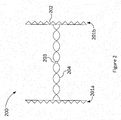
- an example acoustic levitation system is shown comprising two speaker arrays 201a, 201b each formed of a plurality of loudspeakers 202. Note that these are shown in only two dimensions for the sake of clarity (arranged in a row rather than an array).
- the speaker arrays 201a, 201b are controlled to output sound waves into a levitation region (between the two arrays 201a, 201b) such that a standing wave 204 is formed in the levitation region.
- a standing wave 204 is formed in the levitation region.
- an alternative to multiple speaker arrays is a single speaker array and a sound reflector for reflecting sound waves emitted by the single speaker array, as this arrangement is also capable of generating standing waves in the levitation region.
- Further speaker arrays 201 may also be used to generate extra nodes which can be controlled to overlap in space to provide further restoring force and therefore stability.
- a particle 203 located at a node of the standing wave 204 will experience a restoring force due to the increasing pressure around it. If the formed standing wave 204 is of sufficient amplitude, the particle 203 will remain at the node location (it will "levitate") even against the force of gravity.
- the position of the node in which the particle 203 is located can be controlled. Hence, the position of the particle 203 within the levitation region can be controlled. This technique is referred to as acoustic levitation.
- Acoustic levitation can be used to levitate small items such as polystyrene spheres, but can also be used to levitate larger items such as toothpicks, provided that the restorative force provided by the sound is sufficient to counteract the items weight.
- high amplitude sound waves are usually used, e.g. 160dB.
- Frequencies above the human hearing range (which typically extends to a maximum of 20kHz), i.e. ultrasound, can be used in order to minimise hearing damage when using such loud amplitudes.
- the levitating arrangement 101 in this example is an acoustic levitation arrangement which comprises three speaker arrays 101a, 101b, 101c each comprising one or more loudspeakers for outputting sound into a display volume.
- the speaker arrays 101a, 101b, 101c may define the edges of the display volume, or the display volume may be a sub-region of the space enclosed by the speaker arrays 101a, 101b, 101c.
- typically an acoustic levitation system can levitate particles anywhere in space from a maximum distance from the speakers up to a minimum distance from the speakers. The maximum distance is limited by the maximum amplitude of the sound emitted by the speakers, and the minimum distance is limited by how close to the speakers a node can be formed (which depends on the frequency of the emitted sound, for example).
- the levitating arrangement 101 need only comprise a single speaker 102 and a reflector for reflecting sound emitted by the speaker 102. However many speakers 102 are used and however they are arranged, the levitating arrangement 101 is constructed and arranged to controllably lift and move the light source 103 to traverse positions within the display volume.
- the levitating arrangement 101 uses a different arrangement to lift and move the light source 103, such as magnetic levitation.
- the levitating arrangement 101 may not comprise any speakers.
- the levitating arrangement 101 comprises a plurality of electromagnets for generating a variable and controllable magnetic field within the display volume.
- the same effect of controllably lifting and moving the light source 103 can be achieved if the light source 103 itself is magnetic (e.g. constructed of or including a ferromagnetic material).
- the light source 103 comprises at least one source of visible light for emitting visible light from within the display volume.
- the light source 103 may be for example an LED (light emitting diode).
- An example light source 103 is described in more detail below in relation to Figure 3 .
- the transmitter 104 is constructed and arranged to wirelessly control the light source 103 by at least controllably providing power to the light source 103 to thereby control the light emitted by the light source 103.
- the transmitter 104 comprises an induction coil for wirelessly transferring power to the light source 103 as described in more detail below in relation to Figure 3 .
- the light emitted by the light source 103 can be controlled by the transmitter 104 as the light source 103 is moved through the display volume by the levitating arrangement 101 in order to render a 3D image. That is, when located at a given position within the display volume (which corresponds to a particular location in the desired 3D image), the light source 103 is controlled by the transmitter 104 to output light in accordance with at least one of a luminance value or colour value at a location in the 3D image data which corresponds to that position of the light source 103.
- FIG. 3 shows an example light source 103 in more detail.
- the light source 103 comprises a light emitter 301, a receiver 302, and optionally a converter 303.
- the light emitter 301 is operatively coupled to the receiver 302, e.g. via a wired connection.
- the converter 303 is present, the converter 303 is operatively coupled to each of the light emitter 301 and the receiver 302, e.g. via a wired connection.
- the light emitter 301 in this example is a small, lightweight device for generating visible light in response to an electrical current.
- suitable devices include LEDs and OLEDs (organic light emitting diodes).
- a lightweight light emitter 301 is advantageous due to possible limitations of the levitating arrangement 101. For example, in general a magnetic levitation arrangement is typically able to lift and move heavier items than an acoustic levitation arrangement. Note that similar considerations apply to the light source 103 as a whole (i.e. to the receiver 302 and, when present, converter 303).
- the receiver 302 is configured to wirelessly receive power and optionally control signals from the transmitter 104.
- the transmitter 104 may comprise an induction coil.
- the induction coil of the transmitter 104 is a transmitting induction coil and the receiver 302 comprises a receiving induction coil.
- power can be transferred to the light source 103 wirelessly by electromagnetic induction.
- Inductive transfer of power requires the use of an alternating current (AC).
- AC alternating current
- the converter 303 is used to convert received AC power at the receiver 302 into a form suitable for powering the light emitter 301.
- the converter 303 may comprise a half-or full-bridge rectifier for converting the received AC current into direct current (DC) for powering the light emitter 301.
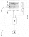
- FIG. 4 shows an example display system 400 in accordance with an example implementation of the present invention.
- the display system 400 comprises a controller 402 arranged to control the levitating arrangement 101 and the transmitter 104 of the display device 100 described above.
- the levitating arrangement 101 comprises a single array of speakers and an audio reflector 105 for reflecting sound generated by the speakers to thereby generate standing waves for lifting and moving the light source 103 (as described above).
- the controller 402 is configured to access image data 401 defining a 3D image as at least one of a luminance value and a colour value at respective locations within the 3D image.
- the image data 401 may be accessed from a local memory or other data storage at the controller 402 or may be accessed over a wired or wireless network from a remote memory or other data storage.
- the 3D image may be defined by the image data 401 as a plurality of "voxels" (volumetric pixels), each having a respective luminance value or colour value or both.
- voxels volumetric pixels
- each voxel location maps to a position within the display volume.
- the controller 402 is configured to control the levitating arrangement 101 in order to move the light source 103 trapped at a node of a standing wave generated by the speakers of the levitating arrangement 101. This is done by controlling the sound emitted by the speakers such that the trapping node of the standing wave moves within the display volume.
- the light source 103 is moved along path 150. Sixty locations of the light source 103 as it moves are shown but, for the avoidance of doubt, note that in this example there is only a single light source 103. Note also that the movement along path 150 is only shown in 2D for the sake of clarity.
- the path 150 will, in general, traverse a 3D volume within the display region, the size of which depends on the particular 3D image to be rendered (the light source 103 need not be moved to locations outside the 3D image).
- the controller 402 is also configured to control the light emitted by the light emitter 301 of the light source 103 via the transmitter 104 in accordance with the luminance and/or colour values of the 3D image data.
- the controller 402 may control the levitating arrangement 101 to move the light source 103 to locations corresponding to each voxel of the 3D image in turn, while simultaneously controlling the transmitter 104 to vary the light emitted by the light source 103 to have the luminance value and/or colour value specified for that voxel location in the 3D image data 401.
- this is performed sufficiently quickly, a human viewer sees the 3D image rendered due to persistence of vision.
- the light source 103 is moved through sixty voxel locations by the controller 402 using the levitating arrangement 101 whilst the light source 103 is turned on and off by the controller 402 using the transmitter 104 to form an image of the letter "H".
- the image may be a static image in which case the motion 150 and control of the light source 103 through the display volume is repeated as above.
- the number of repetitions of path 150 in a second defines a frame rate.
- the motion 150 may be repeated, but the control of the emitted light varies from frame to frame.
- the display device 100 may also be used to display colour images.
- the light source 103 is arranged as shown in Figure 5 .
- the light source 103 of these examples comprises a plurality of light emitters 301 for emitting light of different respective colours (frequencies).
- the light source 103 comprises a red LED 301, a green LED 301b, and a blue LED 301c.
- the receiver 302 and (optionally) converter 303 operate as before (see Figure 3 ).
- a light source controller 304 is additionally provided which is operatively coupled (e.g. via wired connections) to the receiver 302 (or converter 303 when present) and each of the LEDs 301 a-c.
- the light source controller 304 is configured to selectively provide power from the receiver 302 to each of the individual LEDs 301 a-c in accordance with the image data. To do so, in this example the light source controller 304 is configured to receive a data signal e.g. via the receiver 302 using power modulation. This functionality may be provided by one or more separate receivers (not shown in Figure 5 ) such as an additional receiving antenna. In such cases, the data signal may be transmitted to the light source 103 using the transmitter 104, or may be transmitted using one or more separate transmitters (not shown) such as an additional transmitting antenna, for example using Bluetooth or WiFi.
- the data signal specifies how much power to provide to each of the LEDs 301a-c.
- the data signal may specify a colour as a HEX value (#RRGGBB) representing the proportions of Red, Green, and Blue components in a desired output colour (i.e. the colour required at the current voxel location of the light source 103).
- the light source controller 304 is configured to interpret the data signal and selectively provide power from the receiver 302 to each of the LEDs 301a-c accordingly.
- the colour of the light output by the light source 103 can be controlled and therefore a colour 3D image can be rendered.
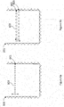
- Some levitation arrangements 101 are capable of controlling the position of more than one item at once (e.g. an acoustic levitation arrangement). Hence, there may be more than one light source 103 present in the display volume at once. Two examples of this are shown schematically in Figure 6a and 7b.
- each light source 103 there are fourteen light sources 103 present.
- the position of each light source 103 is controlled by the levitating arrangement 101 and the light output of each light sources 103 is controlled by the transmitter 104 (not shown).
- the fourteen light sources 103 are arranged in a line 601.
- each light source 103 may be trapped in a successive node of the standing wave (see, for illustration, the standing wave 204 shown in Figure 2 ).
- the line 601 of light sources 103 can thus be moved up and down within the display volume as a unit by simply varying the position of the standing wave.
- each light source 103 may additionally comprise a light source controller 304 similar to that mentioned above in relation to Figure 5 for receiving a wireless data signal.
- the light source controller 304 controls only at least the single light emitter 301 of the light source 103.
- the light output of each light source 103 can be individually controlled via the data signal(s) to each light source controller 304 even when the power transmitted to each light source 103 is the same.
- each line 602, 603 may be controlled by generating a respective first and second standing wave within the display volume.
- the lines 602, 603 can move around each other in space. Indeed, the lines 602, 603 may move "through" each other if the individual light sources 103 of one line are off-set with respect to the other as shown in Figure 6b .
- processor or processing system or circuitry referred to herein may in practice be provided by a single chip or integrated circuit or plural chips or integrated circuits, optionally provided as a chipset, an application-specific integrated circuit (ASIC), field-programmable gate array (FPGA), digital signal processor (DSP), graphics processing units (GPUs), etc.
- the chip or chips may comprise circuitry (as well as possibly firmware) for embodying at least one or more of a data processor or processors and a digital signal processor or processors, which are configurable so as to operate in accordance with the exemplary embodiments.
- the exemplary embodiments may be implemented at least in part by computer software stored in (non-transitory) memory and executable by the processor, or by hardware, or by a combination of tangibly stored software and hardware (and tangibly stored firmware).
Landscapes
- Engineering & Computer Science (AREA)
- Physics & Mathematics (AREA)
- Computer Hardware Design (AREA)
- General Physics & Mathematics (AREA)
- Theoretical Computer Science (AREA)
- Multimedia (AREA)
- Signal Processing (AREA)
- Testing, Inspecting, Measuring Of Stereoscopic Televisions And Televisions (AREA)
Description
- The present disclosure relates to a display apparatus and method for rendering 3D images.
- A swept volume display is a type of volumetric display device for rendering three-dimensional (3D) images, which can be either static images or video images. In such devices, a varying two-dimensional (2D) image is projected onto a rapidly moving display screen in order to create the illusion of a 3D image to a human viewer through the phenomenon of persistence of vision.
- According to a first aspect disclosed herein, there is provided a display apparatus for rendering a 3D image from image data which specifies the 3D image as at least one of a luminance value and a colour value at respective locations within the 3D image, the display apparatus comprising: at least one light source for outputting light; a levitating arrangement constructed and arranged to controllably lift and move the light source to traverse positions within a display volume; and a controller constructed and arranged to control the light source to render the 3D image within the display volume by wirelessly controlling the light source, when located at a given position within the display volume, to output light in accordance with the at least one of a luminance value or colour value specified at the location in the 3D image data that corresponds to that position.
- In an example, the display apparatus comprises a plurality of light sources for outputting light which may be lifted and moved by the levitating arrangement and controlled by the controller.
- In an example, the levitating arrangement is configured to arrange the plurality of light sources in at least one line when lifted by the levitating arrangement.
- In an example, the levitating arrangement is configured to arrange the plurality of light sources in at least two lines when lifted by the levitating arrangement.
- In an example, the levitating arrangement is configured to arrange the plurality of light sources in at least one plane when lifted by the levitating arrangement.
- In an example, the levitating arrangement comprises a plurality of speakers constructed and arranged to move the light source via acoustic levitation. The speakers may emit sound having frequencies above the human hearing range (e.g. ultrasound) for the purposes of acoustic levitation. The speakers may emit no frequencies within the human hearing range.
- In an example, the levitating arrangement comprises a plurality of electromagnets constructed and arranged to move the light source via magnetic levitation.
- In an example, the display apparatus comprises a transmitter for transmitting electrical power to the at least one light source; and wherein the controller is configured to wirelessly control the light source by controlling the transmission of electrical power to the light source by the transmitter.
- In an example, the transmitter comprises a transmitting coil and the at least one light source comprises a receiving coil, whereby the electrical power is transmissible from the transmitter to the at least one light source via electromagnetic induction.
- In an example, the at least one light source comprises at least one LED.
- In an example, the at least one light source comprises at least two light emitters configured to generate visible-spectrum light of different wavelengths. The light source may comprise a red light emitter, a green light emitter, and a blue light emitter.
- According to a second aspect disclosed herein, there is provided a method of rendering a 3D image from image data which specifies the 3D image as at least one of a luminance value and a colour value at respective locations within the 3D image, the method comprising: controllably levitating and moving at least one light source to traverse positions within a display volume; and controlling the light source to render the 3D image within the display volume by wirelessly controlling the light source, when located at a given position within the display volume, to output light in accordance with the at least one of a luminance value or colour value specified at the location in the 3D image data that corresponds to that position.
- In an example, the levitating and moving is carried out using acoustic levitation.
- In an example, the 3D image is a static 3D image.
- In an example, video 3D image.
- To assist understanding of the present disclosure and to show how embodiments may be put into effect, reference is made by way of example to the accompanying drawings in which:
-
Figure 1 shows schematically an example of a display apparatus in accordance with an embodiment of the present invention; -
Figure 2 is a schematic diagram illustrating acoustic levitation; -
Figure 3 shows schematically an example of a light source for use in the display apparatus ofFigure 1 ; -
Figure 4 shows schematically operation of an example of a display apparatus in accordance with an embodiment of the present invention; -
Figure 5 shows schematically an alternative light source for rendering colour 3D images; -
Figure 6a shows schematically an example in which multiple light sources arranged in a line are used to render a 3D image; and -
Figure 6b shows an example in which multiple light sources arranged in two lines are used to render a 3D image. - There is described herein a display apparatus for rendering a 3D image from image data which specifies the 3D image as at least one of a luminance value and a colour value at respective locations within the 3D image. The display apparatus has at least one light source for outputting light. A levitating arrangement controllably lifts and moves the light source to traverse positions within a display volume. A controller controls the light source to render the 3D image within the display volume by wirelessly controlling the light source, when located at a given position within the display volume, to output light in accordance with the at least one of a luminance value or colour value specified at the location in the 3D image data that corresponds to that position.
-
Figure 1 shows adisplay apparatus 100 in accordance with an example of the present invention. Theapparatus 100 comprises alevitating arrangement 101, alight source 103, and atransmitter 104. - In this example, the levitating arrangement is a so-called acoustic levitation system for levitating a
particle 203 using sound waves in a medium (e.g. air). Referring toFigure 2 , an example acoustic levitation system is shown comprising twospeaker arrays loudspeakers 202. Note that these are shown in only two dimensions for the sake of clarity (arranged in a row rather than an array). - The
speaker arrays arrays wave 204 is formed in the levitation region. Note that an alternative to multiple speaker arrays is a single speaker array and a sound reflector for reflecting sound waves emitted by the single speaker array, as this arrangement is also capable of generating standing waves in the levitation region. - Further speaker arrays 201 (e.g. three, four, or more speaker arrays) may also be used to generate extra nodes which can be controlled to overlap in space to provide further restoring force and therefore stability.
- In any case, a
particle 203 located at a node of the standingwave 204 will experience a restoring force due to the increasing pressure around it. If the formedstanding wave 204 is of sufficient amplitude, theparticle 203 will remain at the node location (it will "levitate") even against the force of gravity. By manipulating the sound output by the speaker array(s) 201, the position of the node in which theparticle 203 is located can be controlled. Hence, the position of theparticle 203 within the levitation region can be controlled. This technique is referred to as acoustic levitation. - Acoustic levitation can be used to levitate small items such as polystyrene spheres, but can also be used to levitate larger items such as toothpicks, provided that the restorative force provided by the sound is sufficient to counteract the items weight. Thus, high amplitude sound waves are usually used, e.g. 160dB. Frequencies above the human hearing range (which typically extends to a maximum of 20kHz), i.e. ultrasound, can be used in order to minimise hearing damage when using such loud amplitudes.
- Returning to
Figure 1 , thelevitating arrangement 101 in this example is an acoustic levitation arrangement which comprises threespeaker arrays speaker arrays speaker arrays - Although shown comprising three
speaker arrays Figure 1 , it is appreciated that thelevitating arrangement 101 need only comprise a single speaker 102 and a reflector for reflecting sound emitted by the speaker 102. However many speakers 102 are used and however they are arranged, thelevitating arrangement 101 is constructed and arranged to controllably lift and move thelight source 103 to traverse positions within the display volume. - In other examples, the
levitating arrangement 101 uses a different arrangement to lift and move thelight source 103, such as magnetic levitation. In such cases, thelevitating arrangement 101 may not comprise any speakers. For example, in a magnetic levitation case, thelevitating arrangement 101 comprises a plurality of electromagnets for generating a variable and controllable magnetic field within the display volume. Hence, the same effect of controllably lifting and moving thelight source 103 can be achieved if thelight source 103 itself is magnetic (e.g. constructed of or including a ferromagnetic material). - The
light source 103 comprises at least one source of visible light for emitting visible light from within the display volume. Thelight source 103 may be for example an LED (light emitting diode). An examplelight source 103 is described in more detail below in relation toFigure 3 . - The
transmitter 104 is constructed and arranged to wirelessly control thelight source 103 by at least controllably providing power to thelight source 103 to thereby control the light emitted by thelight source 103. In an example, thetransmitter 104 comprises an induction coil for wirelessly transferring power to thelight source 103 as described in more detail below in relation toFigure 3 . - Hence, the light emitted by the
light source 103 can be controlled by thetransmitter 104 as thelight source 103 is moved through the display volume by the levitatingarrangement 101 in order to render a 3D image. That is, when located at a given position within the display volume (which corresponds to a particular location in the desired 3D image), thelight source 103 is controlled by thetransmitter 104 to output light in accordance with at least one of a luminance value or colour value at a location in the 3D image data which corresponds to that position of thelight source 103. -
Figure 3 shows an examplelight source 103 in more detail. Thelight source 103 comprises alight emitter 301, areceiver 302, and optionally aconverter 303. Thelight emitter 301 is operatively coupled to thereceiver 302, e.g. via a wired connection. When theconverter 303 is present, theconverter 303 is operatively coupled to each of thelight emitter 301 and thereceiver 302, e.g. via a wired connection. - The
light emitter 301 in this example is a small, lightweight device for generating visible light in response to an electrical current. Examples of suitable devices include LEDs and OLEDs (organic light emitting diodes). Alightweight light emitter 301 is advantageous due to possible limitations of the levitatingarrangement 101. For example, in general a magnetic levitation arrangement is typically able to lift and move heavier items than an acoustic levitation arrangement. Note that similar considerations apply to thelight source 103 as a whole (i.e. to thereceiver 302 and, when present, converter 303). - The
receiver 302 is configured to wirelessly receive power and optionally control signals from thetransmitter 104. As mentioned above, thetransmitter 104 may comprise an induction coil. In these examples, the induction coil of thetransmitter 104 is a transmitting induction coil and thereceiver 302 comprises a receiving induction coil. Thus, power can be transferred to thelight source 103 wirelessly by electromagnetic induction. - Inductive transfer of power requires the use of an alternating current (AC). If the
light emitter 301 is not suitable to be run off AC power, then theconverter 303 is used to convert received AC power at thereceiver 302 into a form suitable for powering thelight emitter 301. For example, theconverter 303 may comprise a half-or full-bridge rectifier for converting the received AC current into direct current (DC) for powering thelight emitter 301. -
Figure 4 shows anexample display system 400 in accordance with an example implementation of the present invention. Thedisplay system 400 comprises acontroller 402 arranged to control the levitatingarrangement 101 and thetransmitter 104 of thedisplay device 100 described above. In this example, the levitatingarrangement 101 comprises a single array of speakers and anaudio reflector 105 for reflecting sound generated by the speakers to thereby generate standing waves for lifting and moving the light source 103 (as described above). - The
controller 402 is configured to accessimage data 401 defining a 3D image as at least one of a luminance value and a colour value at respective locations within the 3D image. Theimage data 401 may be accessed from a local memory or other data storage at thecontroller 402 or may be accessed over a wired or wireless network from a remote memory or other data storage. - The 3D image may be defined by the
image data 401 as a plurality of "voxels" (volumetric pixels), each having a respective luminance value or colour value or both. When the 3D image is displayed within the display volume of thedisplay device 100, each voxel location maps to a position within the display volume. - The
controller 402 is configured to control the levitatingarrangement 101 in order to move thelight source 103 trapped at a node of a standing wave generated by the speakers of the levitatingarrangement 101. This is done by controlling the sound emitted by the speakers such that the trapping node of the standing wave moves within the display volume. In this example, thelight source 103 is moved alongpath 150. Sixty locations of thelight source 103 as it moves are shown but, for the avoidance of doubt, note that in this example there is only a singlelight source 103. Note also that the movement alongpath 150 is only shown in 2D for the sake of clarity. Thepath 150 will, in general, traverse a 3D volume within the display region, the size of which depends on the particular 3D image to be rendered (thelight source 103 need not be moved to locations outside the 3D image). - The
controller 402 is also configured to control the light emitted by thelight emitter 301 of thelight source 103 via thetransmitter 104 in accordance with the luminance and/or colour values of the 3D image data. For example, thecontroller 402 may control the levitatingarrangement 101 to move thelight source 103 to locations corresponding to each voxel of the 3D image in turn, while simultaneously controlling thetransmitter 104 to vary the light emitted by thelight source 103 to have the luminance value and/or colour value specified for that voxel location in the3D image data 401. When this is performed sufficiently quickly, a human viewer sees the 3D image rendered due to persistence of vision. - In
Figure 4 , thelight source 103 is moved through sixty voxel locations by thecontroller 402 using the levitatingarrangement 101 whilst thelight source 103 is turned on and off by thecontroller 402 using thetransmitter 104 to form an image of the letter "H". The image may be a static image in which case themotion 150 and control of thelight source 103 through the display volume is repeated as above. The number of repetitions ofpath 150 in a second defines a frame rate. For non-static (e.g. video) 3D images, themotion 150 may be repeated, but the control of the emitted light varies from frame to frame. - The
display device 100 may also be used to display colour images. In such examples, thelight source 103 is arranged as shown inFigure 5 . Thelight source 103 of these examples comprises a plurality oflight emitters 301 for emitting light of different respective colours (frequencies). InFigure 5 , thelight source 103 comprises ared LED 301, agreen LED 301b, and ablue LED 301c. Thereceiver 302 and (optionally)converter 303 operate as before (seeFigure 3 ). Alight source controller 304 is additionally provided which is operatively coupled (e.g. via wired connections) to the receiver 302 (orconverter 303 when present) and each of theLEDs 301 a-c. - The
light source controller 304 is configured to selectively provide power from thereceiver 302 to each of theindividual LEDs 301 a-c in accordance with the image data. To do so, in this example thelight source controller 304 is configured to receive a data signal e.g. via thereceiver 302 using power modulation. This functionality may be provided by one or more separate receivers (not shown inFigure 5 ) such as an additional receiving antenna. In such cases, the data signal may be transmitted to thelight source 103 using thetransmitter 104, or may be transmitted using one or more separate transmitters (not shown) such as an additional transmitting antenna, for example using Bluetooth or WiFi. - The data signal specifies how much power to provide to each of the
LEDs 301a-c. For example, the data signal may specify a colour as a HEX value (#RRGGBB) representing the proportions of Red, Green, and Blue components in a desired output colour (i.e. the colour required at the current voxel location of the light source 103). - The
light source controller 304 is configured to interpret the data signal and selectively provide power from thereceiver 302 to each of theLEDs 301a-c accordingly. Thus, the colour of the light output by thelight source 103 can be controlled and therefore a colour 3D image can be rendered. - Some levitation
arrangements 101 are capable of controlling the position of more than one item at once (e.g. an acoustic levitation arrangement). Hence, there may be more than onelight source 103 present in the display volume at once. Two examples of this are shown schematically inFigure 6a and 7b. - In the example of
Figure 6a , there are fourteenlight sources 103 present. The position of eachlight source 103 is controlled by the levitatingarrangement 101 and the light output of eachlight sources 103 is controlled by the transmitter 104 (not shown). The fourteenlight sources 103 are arranged in aline 601. For example, eachlight source 103 may be trapped in a successive node of the standing wave (see, for illustration, thestanding wave 204 shown inFigure 2 ). Theline 601 oflight sources 103 can thus be moved up and down within the display volume as a unit by simply varying the position of the standing wave. - In examples such as this in which there are multiple
light sources 103 present, eachlight source 103 may additionally comprise alight source controller 304 similar to that mentioned above in relation toFigure 5 for receiving a wireless data signal. However, in these examples thelight source controller 304 controls only at least thesingle light emitter 301 of thelight source 103. Hence, the light output of eachlight source 103 can be individually controlled via the data signal(s) to eachlight source controller 304 even when the power transmitted to eachlight source 103 is the same. - In the example of
Figure 6b , there are twentylight sources 103 present. Again, the position of each is controlled by the levitatingarrangement 101 and the light output of each is controlled by the transmitted 104 (not shown). The twentylight sources 103 are arranged in twolines first line 602 comprises tenlight sources 103 and thesecond line 603 comprises ten light sources. The position of eachline - As there are no guides or rails or other mechanical arrangement required to move the
light sources 103 around, thelines lines light sources 103 of one line are off-set with respect to the other as shown inFigure 6b . - It will be understood that the processor or processing system or circuitry referred to herein may in practice be provided by a single chip or integrated circuit or plural chips or integrated circuits, optionally provided as a chipset, an application-specific integrated circuit (ASIC), field-programmable gate array (FPGA), digital signal processor (DSP), graphics processing units (GPUs), etc. The chip or chips may comprise circuitry (as well as possibly firmware) for embodying at least one or more of a data processor or processors and a digital signal processor or processors, which are configurable so as to operate in accordance with the exemplary embodiments. In this regard, the exemplary embodiments may be implemented at least in part by computer software stored in (non-transitory) memory and executable by the processor, or by hardware, or by a combination of tangibly stored software and hardware (and tangibly stored firmware).
- Reference is made herein to data storage for storing data. This may be provided by a single device or by plural devices. Suitable devices include for example a hard disk and non-volatile semiconductor memory.
- The examples described herein are to be understood as illustrative examples of embodiments of the invention. Further embodiments and examples are envisaged. Any feature described in relation to any one example or embodiment may be used alone or in combination with other features. In addition, any feature described in relation to any one example or embodiment may also be used in combination with one or more features of any other of the examples or embodiments, or any combination of any other of the examples or embodiments. Furthermore, equivalents and modifications not described herein may also be employed within the scope of the invention, which is defined in the claims.
Claims (15)
- A display apparatus for rendering a 3D image from image data which specifies the 3D image as at least one of a luminance value and a colour value at respective locations within the 3D image, the display apparatus comprising:at least one light source for outputting light;a levitating arrangement constructed and arranged to controllably lift and move the light source to traverse positions within a display volume; anda controller constructed and arranged to control the light source to render the 3D image within the display volume by wirelessly controlling the light source, when located at a given position within the display volume, to output light in accordance with the at least one of a luminance value or colour value specified at the location in the 3D image data that corresponds to that position.
- A display apparatus according to claim 1, comprising a plurality of light sources for outputting light which may be lifted and moved by the levitating arrangement and controlled by the controller.
- A display apparatus according to claim 2, wherein the levitating arrangement is configured to arrange the plurality of light sources in at least one line when lifted by the levitating arrangement.
- A display apparatus according to claim 3, wherein the levitating arrangement is configured to arrange the plurality of light sources in at least two lines when lifted by the levitating arrangement.
- A display apparatus according to any of claims 2 to 4, wherein the levitating arrangement is configured to arrange the plurality of light sources in at least one plane when lifted by the levitating arrangement.
- A display apparatus according to any of claims 1 to 5, wherein the levitating arrangement comprises a plurality of speakers constructed and arranged to move the light source via acoustic levitation.
- A display apparatus according to any of claims 1 to 5, wherein the levitating arrangement comprises a plurality of electromagnets constructed and arranged to move the light source via magnetic levitation.
- A display apparatus according to any of claims 1 to 7, comprising a transmitter for transmitting electrical power to the at least one light source; and wherein the controller is configured to wirelessly control the light source by controlling the transmission of electrical power to the light source by the transmitter.
- A display apparatus according to claim 8, wherein the transmitter comprises a transmitting coil and the at least one light source comprises a receiving coil, whereby the electrical power is transmissible from the transmitter to the at least one light source via electromagnetic induction.
- A display apparatus according to any of claims 1 to 9, wherein the at least one light source comprises at least one LED.
- A display apparatus according to any of claims 1 to 10, wherein the at least one light source comprises at least two light emitters configured to generate visible-spectrum light of different wavelengths.
- A method of rendering a 3D image from image data which specifies the 3D image as at least one of a luminance value and a colour value at respective locations within the 3D image, the method comprising:controllably levitating and moving at least one light source to traverse positions within a display volume; andcontrolling the light source to render the 3D image within the display volume by wirelessly controlling the light source, when located at a given position within the display volume, to output light in accordance with the at least one of a luminance value or colour value specified at the location in the 3D image data that corresponds to that position.
- A method according to claim 12, wherein the levitating and moving is carried out using acoustic levitation.
- A method according to claim 12 or claim 13, wherein the 3D image is a static 3D image.
- A method according to claim 12 or claim 13, wherein the 3D image is a video 3D image.
Priority Applications (2)
| Application Number | Priority Date | Filing Date | Title |
|---|---|---|---|
| EP17182373.5A EP3432299B1 (en) | 2017-07-20 | 2017-07-20 | Display apparatus and method for rendering a 3d image |
| TR2017/11032A TR201711032A2 (en) | 2017-07-20 | 2017-07-27 | Display apparatus and method for rendering a 3D image. |
Applications Claiming Priority (1)
| Application Number | Priority Date | Filing Date | Title |
|---|---|---|---|
| EP17182373.5A EP3432299B1 (en) | 2017-07-20 | 2017-07-20 | Display apparatus and method for rendering a 3d image |
Publications (2)
| Publication Number | Publication Date |
|---|---|
| EP3432299A1 true EP3432299A1 (en) | 2019-01-23 |
| EP3432299B1 EP3432299B1 (en) | 2023-05-31 |
Family
ID=59383487
Family Applications (1)
| Application Number | Title | Priority Date | Filing Date |
|---|---|---|---|
| EP17182373.5A Active EP3432299B1 (en) | 2017-07-20 | 2017-07-20 | Display apparatus and method for rendering a 3d image |
Country Status (2)
| Country | Link |
|---|---|
| EP (1) | EP3432299B1 (en) |
| TR (1) | TR201711032A2 (en) |
Cited By (1)
| Publication number | Priority date | Publication date | Assignee | Title |
|---|---|---|---|---|
| US11448897B2 (en) | 2019-07-02 | 2022-09-20 | Industrial Technology Research Institute | Three-dimensional imaging system and method |
Citations (4)
| Publication number | Priority date | Publication date | Assignee | Title |
|---|---|---|---|---|
| US5929572A (en) * | 1996-09-19 | 1999-07-27 | The United States Of America As Represented By The Secretary Of The Navy | Electroluminescent arrays layered to form a volumetric display |
| US20100328368A1 (en) * | 2008-03-03 | 2010-12-30 | Chen Shuwen | Three dimensional display system and its display control method |
| US20120146885A1 (en) * | 2010-12-14 | 2012-06-14 | Electronics And Telecommunications Research Institute | Volumetric three dimensional panel and display apparatus using the same |
| US20160240118A1 (en) * | 2015-02-12 | 2016-08-18 | Nthdegree Technologies Worldwide Inc. | 3-d display using led pixel layers |
Family Cites Families (2)
| Publication number | Priority date | Publication date | Assignee | Title |
|---|---|---|---|---|
| US20120300298A1 (en) * | 2011-05-29 | 2012-11-29 | Xiao Lin Yu | 3d visual display system and method |
| US20180310380A1 (en) * | 2015-10-26 | 2018-10-25 | Philips Lighting Holding B.V. | Lighting effects |
-
2017
- 2017-07-20 EP EP17182373.5A patent/EP3432299B1/en active Active
- 2017-07-27 TR TR2017/11032A patent/TR201711032A2/en unknown
Patent Citations (4)
| Publication number | Priority date | Publication date | Assignee | Title |
|---|---|---|---|---|
| US5929572A (en) * | 1996-09-19 | 1999-07-27 | The United States Of America As Represented By The Secretary Of The Navy | Electroluminescent arrays layered to form a volumetric display |
| US20100328368A1 (en) * | 2008-03-03 | 2010-12-30 | Chen Shuwen | Three dimensional display system and its display control method |
| US20120146885A1 (en) * | 2010-12-14 | 2012-06-14 | Electronics And Telecommunications Research Institute | Volumetric three dimensional panel and display apparatus using the same |
| US20160240118A1 (en) * | 2015-02-12 | 2016-08-18 | Nthdegree Technologies Worldwide Inc. | 3-d display using led pixel layers |
Non-Patent Citations (3)
| Title |
|---|
| YOICHI OCHIAI ET AL: "Pixie dust : graphics generated by levitated and animated objects in computational acoustic-potential field", ACM TRANSACTIONS ON GRAPHICS (TOG), vol. 33, no. 4, 27 July 2014 (2014-07-27), US, pages 1 - 13, XP055400922, ISSN: 0730-0301, DOI: 10.1145/2601097.2601118 * |
| YOICHI OCHIAI: "8-4: Invited Paper : Pixels towards Pixies: Post-Multimedia interactions with Air-Based Media", S I D INTERNATIONAL SYMPOSIUM. DIGEST OF TECHNICAL PAPERS, vol. 47, no. 1, 4 May 2016 (2016-05-04), US, pages 79 - 82, XP055400700, ISSN: 0097-966X, DOI: 10.1002/sdtp.10615 * |
| YOICHI OCHIAI: "Pixie Dust: Graphical Levitation System (2014-)", YOUTUBE, 26 May 2014 (2014-05-26), pages 1 - 1, XP054977663, Retrieved from the Internet <URL:https://www.youtube.com/watch?v=NLgD3EtxwdY> [retrieved on 20170824] * |
Cited By (1)
| Publication number | Priority date | Publication date | Assignee | Title |
|---|---|---|---|---|
| US11448897B2 (en) | 2019-07-02 | 2022-09-20 | Industrial Technology Research Institute | Three-dimensional imaging system and method |
Also Published As
| Publication number | Publication date |
|---|---|
| TR201711032A2 (en) | 2019-02-21 |
| EP3432299B1 (en) | 2023-05-31 |
Similar Documents
| Publication | Publication Date | Title |
|---|---|---|
| CN112119371B (en) | Modular display device and method for controlling the same | |
| EP3032847B1 (en) | Adjusting speakers using facial recognition | |
| CN103576160B (en) | Distance measuring device and the image processing apparatus including it | |
| US10321232B2 (en) | Distributed amplification for adaptive audio rendering systems | |
| US20100031298A1 (en) | Transmission device, audio-visual environment control device, and audio-visual environment control system | |
| US20190352006A1 (en) | Drone deployed speaker system | |
| US9716878B2 (en) | Volumetric display using acoustic pressure waves | |
| US11030940B2 (en) | Display array with distributed audio | |
| KR102419272B1 (en) | Light emitting sound device, sound output device and display device | |
| CN107690812A (en) | Use the configuration of the ambient light of wireless connection | |
| EP3731537A1 (en) | Systems and methods in tiled display imaging systems | |
| CN112180619B (en) | Three-dimensional imaging system and method | |
| CN112740313A (en) | Display device and control method thereof | |
| US20240210951A1 (en) | Media Playback System | |
| KR20210069197A (en) | Display apparatus and controlling method thereof | |
| EP3432299B1 (en) | Display apparatus and method for rendering a 3d image | |
| US20200359007A1 (en) | Information processing apparatus and information processing method | |
| CN109417675B (en) | Terminal Mixing Products | |
| CN116405840A (en) | Loudspeaker system for arbitrary sound direction presentation | |
| US20260007979A1 (en) | Modular sensory platform | |
| JP2020127266A (en) | Display device | |
| KR20210132950A (en) | Display appartus and power supply | |
| TW201824858A (en) | Aerial display system and floating pixel unit thereof | |
| KR20240083689A (en) | Electronic device and controlling method of electronic device | |
| CN111200678B (en) | Electronic device and audio output method |
Legal Events
| Date | Code | Title | Description |
|---|---|---|---|
| PUAI | Public reference made under article 153(3) epc to a published international application that has entered the european phase |
Free format text: ORIGINAL CODE: 0009012 |
|
| STAA | Information on the status of an ep patent application or granted ep patent |
Free format text: STATUS: THE APPLICATION HAS BEEN PUBLISHED |
|
| AK | Designated contracting states |
Kind code of ref document: A1 Designated state(s): AL AT BE BG CH CY CZ DE DK EE ES FI FR GB GR HR HU IE IS IT LI LT LU LV MC MK MT NL NO PL PT RO RS SE SI SK SM TR |
|
| AX | Request for extension of the european patent |
Extension state: BA ME |
|
| STAA | Information on the status of an ep patent application or granted ep patent |
Free format text: STATUS: REQUEST FOR EXAMINATION WAS MADE |
|
| 17P | Request for examination filed |
Effective date: 20190723 |
|
| RBV | Designated contracting states (corrected) |
Designated state(s): AL AT BE BG CH CY CZ DE DK EE ES FI FR GB GR HR HU IE IS IT LI LT LU LV MC MK MT NL NO PL PT RO RS SE SI SK SM TR |
|
| STAA | Information on the status of an ep patent application or granted ep patent |
Free format text: STATUS: EXAMINATION IS IN PROGRESS |
|
| 17Q | First examination report despatched |
Effective date: 20200306 |
|
| GRAP | Despatch of communication of intention to grant a patent |
Free format text: ORIGINAL CODE: EPIDOSNIGR1 |
|
| STAA | Information on the status of an ep patent application or granted ep patent |
Free format text: STATUS: GRANT OF PATENT IS INTENDED |
|
| INTG | Intention to grant announced |
Effective date: 20221222 |
|
| GRAS | Grant fee paid |
Free format text: ORIGINAL CODE: EPIDOSNIGR3 |
|
| GRAA | (expected) grant |
Free format text: ORIGINAL CODE: 0009210 |
|
| STAA | Information on the status of an ep patent application or granted ep patent |
Free format text: STATUS: THE PATENT HAS BEEN GRANTED |
|
| AK | Designated contracting states |
Kind code of ref document: B1 Designated state(s): AL AT BE BG CH CY CZ DE DK EE ES FI FR GB GR HR HU IE IS IT LI LT LU LV MC MK MT NL NO PL PT RO RS SE SI SK SM TR |
|
| REG | Reference to a national code |
Ref country code: GB Ref legal event code: FG4D Ref country code: CH Ref legal event code: EP |
|
| REG | Reference to a national code |
Ref country code: AT Ref legal event code: REF Ref document number: 1571424 Country of ref document: AT Kind code of ref document: T Effective date: 20230615 Ref country code: DE Ref legal event code: R096 Ref document number: 602017069170 Country of ref document: DE |
|
| REG | Reference to a national code |
Ref country code: IE Ref legal event code: FG4D |
|
| REG | Reference to a national code |
Ref country code: LT Ref legal event code: MG9D |
|
| REG | Reference to a national code |
Ref country code: NL Ref legal event code: MP Effective date: 20230531 |
|
| REG | Reference to a national code |
Ref country code: AT Ref legal event code: MK05 Ref document number: 1571424 Country of ref document: AT Kind code of ref document: T Effective date: 20230531 |
|
| PG25 | Lapsed in a contracting state [announced via postgrant information from national office to epo] |
Ref country code: SE Free format text: LAPSE BECAUSE OF FAILURE TO SUBMIT A TRANSLATION OF THE DESCRIPTION OR TO PAY THE FEE WITHIN THE PRESCRIBED TIME-LIMIT Effective date: 20230531 Ref country code: NO Free format text: LAPSE BECAUSE OF FAILURE TO SUBMIT A TRANSLATION OF THE DESCRIPTION OR TO PAY THE FEE WITHIN THE PRESCRIBED TIME-LIMIT Effective date: 20230831 Ref country code: ES Free format text: LAPSE BECAUSE OF FAILURE TO SUBMIT A TRANSLATION OF THE DESCRIPTION OR TO PAY THE FEE WITHIN THE PRESCRIBED TIME-LIMIT Effective date: 20230531 Ref country code: AT Free format text: LAPSE BECAUSE OF FAILURE TO SUBMIT A TRANSLATION OF THE DESCRIPTION OR TO PAY THE FEE WITHIN THE PRESCRIBED TIME-LIMIT Effective date: 20230531 |
|
| PGFP | Annual fee paid to national office [announced via postgrant information from national office to epo] |
Ref country code: GB Payment date: 20230721 Year of fee payment: 7 |
|
| PG25 | Lapsed in a contracting state [announced via postgrant information from national office to epo] |
Ref country code: RS Free format text: LAPSE BECAUSE OF FAILURE TO SUBMIT A TRANSLATION OF THE DESCRIPTION OR TO PAY THE FEE WITHIN THE PRESCRIBED TIME-LIMIT Effective date: 20230531 Ref country code: PL Free format text: LAPSE BECAUSE OF FAILURE TO SUBMIT A TRANSLATION OF THE DESCRIPTION OR TO PAY THE FEE WITHIN THE PRESCRIBED TIME-LIMIT Effective date: 20230531 Ref country code: NL Free format text: LAPSE BECAUSE OF FAILURE TO SUBMIT A TRANSLATION OF THE DESCRIPTION OR TO PAY THE FEE WITHIN THE PRESCRIBED TIME-LIMIT Effective date: 20230531 Ref country code: LV Free format text: LAPSE BECAUSE OF FAILURE TO SUBMIT A TRANSLATION OF THE DESCRIPTION OR TO PAY THE FEE WITHIN THE PRESCRIBED TIME-LIMIT Effective date: 20230531 Ref country code: LT Free format text: LAPSE BECAUSE OF FAILURE TO SUBMIT A TRANSLATION OF THE DESCRIPTION OR TO PAY THE FEE WITHIN THE PRESCRIBED TIME-LIMIT Effective date: 20230531 Ref country code: IS Free format text: LAPSE BECAUSE OF FAILURE TO SUBMIT A TRANSLATION OF THE DESCRIPTION OR TO PAY THE FEE WITHIN THE PRESCRIBED TIME-LIMIT Effective date: 20230930 Ref country code: HR Free format text: LAPSE BECAUSE OF FAILURE TO SUBMIT A TRANSLATION OF THE DESCRIPTION OR TO PAY THE FEE WITHIN THE PRESCRIBED TIME-LIMIT Effective date: 20230531 Ref country code: GR Free format text: LAPSE BECAUSE OF FAILURE TO SUBMIT A TRANSLATION OF THE DESCRIPTION OR TO PAY THE FEE WITHIN THE PRESCRIBED TIME-LIMIT Effective date: 20230901 |
|
| PGFP | Annual fee paid to national office [announced via postgrant information from national office to epo] |
Ref country code: DE Payment date: 20230719 Year of fee payment: 7 |
|
| PG25 | Lapsed in a contracting state [announced via postgrant information from national office to epo] |
Ref country code: FI Free format text: LAPSE BECAUSE OF FAILURE TO SUBMIT A TRANSLATION OF THE DESCRIPTION OR TO PAY THE FEE WITHIN THE PRESCRIBED TIME-LIMIT Effective date: 20230531 |
|
| PG25 | Lapsed in a contracting state [announced via postgrant information from national office to epo] |
Ref country code: SK Free format text: LAPSE BECAUSE OF FAILURE TO SUBMIT A TRANSLATION OF THE DESCRIPTION OR TO PAY THE FEE WITHIN THE PRESCRIBED TIME-LIMIT Effective date: 20230531 |
|
| PG25 | Lapsed in a contracting state [announced via postgrant information from national office to epo] |
Ref country code: SM Free format text: LAPSE BECAUSE OF FAILURE TO SUBMIT A TRANSLATION OF THE DESCRIPTION OR TO PAY THE FEE WITHIN THE PRESCRIBED TIME-LIMIT Effective date: 20230531 Ref country code: SK Free format text: LAPSE BECAUSE OF FAILURE TO SUBMIT A TRANSLATION OF THE DESCRIPTION OR TO PAY THE FEE WITHIN THE PRESCRIBED TIME-LIMIT Effective date: 20230531 Ref country code: RO Free format text: LAPSE BECAUSE OF FAILURE TO SUBMIT A TRANSLATION OF THE DESCRIPTION OR TO PAY THE FEE WITHIN THE PRESCRIBED TIME-LIMIT Effective date: 20230531 Ref country code: PT Free format text: LAPSE BECAUSE OF FAILURE TO SUBMIT A TRANSLATION OF THE DESCRIPTION OR TO PAY THE FEE WITHIN THE PRESCRIBED TIME-LIMIT Effective date: 20231002 Ref country code: EE Free format text: LAPSE BECAUSE OF FAILURE TO SUBMIT A TRANSLATION OF THE DESCRIPTION OR TO PAY THE FEE WITHIN THE PRESCRIBED TIME-LIMIT Effective date: 20230531 Ref country code: DK Free format text: LAPSE BECAUSE OF FAILURE TO SUBMIT A TRANSLATION OF THE DESCRIPTION OR TO PAY THE FEE WITHIN THE PRESCRIBED TIME-LIMIT Effective date: 20230531 Ref country code: CZ Free format text: LAPSE BECAUSE OF FAILURE TO SUBMIT A TRANSLATION OF THE DESCRIPTION OR TO PAY THE FEE WITHIN THE PRESCRIBED TIME-LIMIT Effective date: 20230531 |
|
| PG25 | Lapsed in a contracting state [announced via postgrant information from national office to epo] |
Ref country code: MC Free format text: LAPSE BECAUSE OF FAILURE TO SUBMIT A TRANSLATION OF THE DESCRIPTION OR TO PAY THE FEE WITHIN THE PRESCRIBED TIME-LIMIT Effective date: 20230531 |
|
| PG25 | Lapsed in a contracting state [announced via postgrant information from national office to epo] |
Ref country code: MC Free format text: LAPSE BECAUSE OF FAILURE TO SUBMIT A TRANSLATION OF THE DESCRIPTION OR TO PAY THE FEE WITHIN THE PRESCRIBED TIME-LIMIT Effective date: 20230531 |
|
| REG | Reference to a national code |
Ref country code: CH Ref legal event code: PL |
|
| REG | Reference to a national code |
Ref country code: DE Ref legal event code: R097 Ref document number: 602017069170 Country of ref document: DE |
|
| REG | Reference to a national code |
Ref country code: BE Ref legal event code: MM Effective date: 20230731 |
|
| PG25 | Lapsed in a contracting state [announced via postgrant information from national office to epo] |
Ref country code: LU Free format text: LAPSE BECAUSE OF NON-PAYMENT OF DUE FEES Effective date: 20230720 |
|
| PG25 | Lapsed in a contracting state [announced via postgrant information from national office to epo] |
Ref country code: LU Free format text: LAPSE BECAUSE OF NON-PAYMENT OF DUE FEES Effective date: 20230720 |
|
| PLBE | No opposition filed within time limit |
Free format text: ORIGINAL CODE: 0009261 |
|
| STAA | Information on the status of an ep patent application or granted ep patent |
Free format text: STATUS: NO OPPOSITION FILED WITHIN TIME LIMIT |
|
| REG | Reference to a national code |
Ref country code: IE Ref legal event code: MM4A |
|
| PG25 | Lapsed in a contracting state [announced via postgrant information from national office to epo] |
Ref country code: CH Free format text: LAPSE BECAUSE OF NON-PAYMENT OF DUE FEES Effective date: 20230731 |
|
| PG25 | Lapsed in a contracting state [announced via postgrant information from national office to epo] |
Ref country code: SI Free format text: LAPSE BECAUSE OF FAILURE TO SUBMIT A TRANSLATION OF THE DESCRIPTION OR TO PAY THE FEE WITHIN THE PRESCRIBED TIME-LIMIT Effective date: 20230531 |
|
| 26N | No opposition filed |
Effective date: 20240301 |
|
| PG25 | Lapsed in a contracting state [announced via postgrant information from national office to epo] |
Ref country code: SI Free format text: LAPSE BECAUSE OF FAILURE TO SUBMIT A TRANSLATION OF THE DESCRIPTION OR TO PAY THE FEE WITHIN THE PRESCRIBED TIME-LIMIT Effective date: 20230531 Ref country code: IT Free format text: LAPSE BECAUSE OF FAILURE TO SUBMIT A TRANSLATION OF THE DESCRIPTION OR TO PAY THE FEE WITHIN THE PRESCRIBED TIME-LIMIT Effective date: 20230531 Ref country code: FR Free format text: LAPSE BECAUSE OF NON-PAYMENT OF DUE FEES Effective date: 20230731 Ref country code: BE Free format text: LAPSE BECAUSE OF NON-PAYMENT OF DUE FEES Effective date: 20230731 |
|
| PG25 | Lapsed in a contracting state [announced via postgrant information from national office to epo] |
Ref country code: IE Free format text: LAPSE BECAUSE OF NON-PAYMENT OF DUE FEES Effective date: 20230720 |
|
| PG25 | Lapsed in a contracting state [announced via postgrant information from national office to epo] |
Ref country code: IE Free format text: LAPSE BECAUSE OF NON-PAYMENT OF DUE FEES Effective date: 20230720 |
|
| PG25 | Lapsed in a contracting state [announced via postgrant information from national office to epo] |
Ref country code: BG Free format text: LAPSE BECAUSE OF FAILURE TO SUBMIT A TRANSLATION OF THE DESCRIPTION OR TO PAY THE FEE WITHIN THE PRESCRIBED TIME-LIMIT Effective date: 20230531 |
|
| PG25 | Lapsed in a contracting state [announced via postgrant information from national office to epo] |
Ref country code: BG Free format text: LAPSE BECAUSE OF FAILURE TO SUBMIT A TRANSLATION OF THE DESCRIPTION OR TO PAY THE FEE WITHIN THE PRESCRIBED TIME-LIMIT Effective date: 20230531 |
|
| REG | Reference to a national code |
Ref country code: DE Ref legal event code: R119 Ref document number: 602017069170 Country of ref document: DE |
|
| GBPC | Gb: european patent ceased through non-payment of renewal fee |
Effective date: 20240720 |
|
| PG25 | Lapsed in a contracting state [announced via postgrant information from national office to epo] |
Ref country code: DE Free format text: LAPSE BECAUSE OF NON-PAYMENT OF DUE FEES Effective date: 20250201 |
|
| PG25 | Lapsed in a contracting state [announced via postgrant information from national office to epo] |
Ref country code: GB Free format text: LAPSE BECAUSE OF NON-PAYMENT OF DUE FEES Effective date: 20240720 |
|
| PG25 | Lapsed in a contracting state [announced via postgrant information from national office to epo] |
Ref country code: CY Free format text: LAPSE BECAUSE OF FAILURE TO SUBMIT A TRANSLATION OF THE DESCRIPTION OR TO PAY THE FEE WITHIN THE PRESCRIBED TIME-LIMIT; INVALID AB INITIO Effective date: 20170720 |
|
| PG25 | Lapsed in a contracting state [announced via postgrant information from national office to epo] |
Ref country code: HU Free format text: LAPSE BECAUSE OF FAILURE TO SUBMIT A TRANSLATION OF THE DESCRIPTION OR TO PAY THE FEE WITHIN THE PRESCRIBED TIME-LIMIT; INVALID AB INITIO Effective date: 20170720 |
|
| PGFP | Annual fee paid to national office [announced via postgrant information from national office to epo] |
Ref country code: TR Payment date: 20250718 Year of fee payment: 9 |