EP3432006A1 - Electronics device with current sensor integrated into a heat sink - Google Patents
Electronics device with current sensor integrated into a heat sink Download PDFInfo
- Publication number
- EP3432006A1 EP3432006A1 EP18171375.1A EP18171375A EP3432006A1 EP 3432006 A1 EP3432006 A1 EP 3432006A1 EP 18171375 A EP18171375 A EP 18171375A EP 3432006 A1 EP3432006 A1 EP 3432006A1
- Authority
- EP
- European Patent Office
- Prior art keywords
- current
- electronic device
- current sensor
- cooling element
- power line
- Prior art date
- Legal status (The legal status is an assumption and is not a legal conclusion. Google has not performed a legal analysis and makes no representation as to the accuracy of the status listed.)
- Pending
Links
Images

Classifications
-
- H—ELECTRICITY
- H01—ELECTRIC ELEMENTS
- H01L—SEMICONDUCTOR DEVICES NOT COVERED BY CLASS H10
- H01L23/00—Details of semiconductor or other solid state devices
- H01L23/34—Arrangements for cooling, heating, ventilating or temperature compensation ; Temperature sensing arrangements
- H01L23/36—Selection of materials, or shaping, to facilitate cooling or heating, e.g. heatsinks
- H01L23/367—Cooling facilitated by shape of device
- H01L23/3675—Cooling facilitated by shape of device characterised by the shape of the housing
-
- G—PHYSICS
- G01—MEASURING; TESTING
- G01R—MEASURING ELECTRIC VARIABLES; MEASURING MAGNETIC VARIABLES
- G01R15/00—Details of measuring arrangements of the types provided for in groups G01R17/00 - G01R29/00, G01R33/00 - G01R33/26 or G01R35/00
- G01R15/14—Adaptations providing voltage or current isolation, e.g. for high-voltage or high-current networks
- G01R15/20—Adaptations providing voltage or current isolation, e.g. for high-voltage or high-current networks using galvano-magnetic devices, e.g. Hall-effect devices, i.e. measuring a magnetic field via the interaction between a current and a magnetic field, e.g. magneto resistive or Hall effect devices
- G01R15/202—Adaptations providing voltage or current isolation, e.g. for high-voltage or high-current networks using galvano-magnetic devices, e.g. Hall-effect devices, i.e. measuring a magnetic field via the interaction between a current and a magnetic field, e.g. magneto resistive or Hall effect devices using Hall-effect devices
-
- B—PERFORMING OPERATIONS; TRANSPORTING
- B60—VEHICLES IN GENERAL
- B60R—VEHICLES, VEHICLE FITTINGS, OR VEHICLE PARTS, NOT OTHERWISE PROVIDED FOR
- B60R16/00—Electric or fluid circuits specially adapted for vehicles and not otherwise provided for; Arrangement of elements of electric or fluid circuits specially adapted for vehicles and not otherwise provided for
- B60R16/02—Electric or fluid circuits specially adapted for vehicles and not otherwise provided for; Arrangement of elements of electric or fluid circuits specially adapted for vehicles and not otherwise provided for electric constitutive elements
-
- G—PHYSICS
- G01—MEASURING; TESTING
- G01R—MEASURING ELECTRIC VARIABLES; MEASURING MAGNETIC VARIABLES
- G01R1/00—Details of instruments or arrangements of the types included in groups G01R5/00 - G01R13/00 and G01R31/00
- G01R1/02—General constructional details
- G01R1/18—Screening arrangements against electric or magnetic fields, e.g. against earth's field
-
- G—PHYSICS
- G01—MEASURING; TESTING
- G01R—MEASURING ELECTRIC VARIABLES; MEASURING MAGNETIC VARIABLES
- G01R15/00—Details of measuring arrangements of the types provided for in groups G01R17/00 - G01R29/00, G01R33/00 - G01R33/26 or G01R35/00
- G01R15/14—Adaptations providing voltage or current isolation, e.g. for high-voltage or high-current networks
- G01R15/20—Adaptations providing voltage or current isolation, e.g. for high-voltage or high-current networks using galvano-magnetic devices, e.g. Hall-effect devices, i.e. measuring a magnetic field via the interaction between a current and a magnetic field, e.g. magneto resistive or Hall effect devices
- G01R15/207—Constructional details independent of the type of device used
-
- H—ELECTRICITY
- H01—ELECTRIC ELEMENTS
- H01L—SEMICONDUCTOR DEVICES NOT COVERED BY CLASS H10
- H01L23/00—Details of semiconductor or other solid state devices
- H01L23/52—Arrangements for conducting electric current within the device in operation from one component to another, i.e. interconnections, e.g. wires, lead frames
- H01L23/538—Arrangements for conducting electric current within the device in operation from one component to another, i.e. interconnections, e.g. wires, lead frames the interconnection structure between a plurality of semiconductor chips being formed on, or in, insulating substrates
- H01L23/5386—Geometry or layout of the interconnection structure
-
- H—ELECTRICITY
- H01—ELECTRIC ELEMENTS
- H01L—SEMICONDUCTOR DEVICES NOT COVERED BY CLASS H10
- H01L25/00—Assemblies consisting of a plurality of individual semiconductor or other solid state devices ; Multistep manufacturing processes thereof
- H01L25/03—Assemblies consisting of a plurality of individual semiconductor or other solid state devices ; Multistep manufacturing processes thereof all the devices being of a type provided for in the same subgroup of groups H01L27/00 - H01L33/00, or in a single subclass of H10K, H10N, e.g. assemblies of rectifier diodes
- H01L25/04—Assemblies consisting of a plurality of individual semiconductor or other solid state devices ; Multistep manufacturing processes thereof all the devices being of a type provided for in the same subgroup of groups H01L27/00 - H01L33/00, or in a single subclass of H10K, H10N, e.g. assemblies of rectifier diodes the devices not having separate containers
- H01L25/07—Assemblies consisting of a plurality of individual semiconductor or other solid state devices ; Multistep manufacturing processes thereof all the devices being of a type provided for in the same subgroup of groups H01L27/00 - H01L33/00, or in a single subclass of H10K, H10N, e.g. assemblies of rectifier diodes the devices not having separate containers the devices being of a type provided for in group H01L29/00
- H01L25/072—Assemblies consisting of a plurality of individual semiconductor or other solid state devices ; Multistep manufacturing processes thereof all the devices being of a type provided for in the same subgroup of groups H01L27/00 - H01L33/00, or in a single subclass of H10K, H10N, e.g. assemblies of rectifier diodes the devices not having separate containers the devices being of a type provided for in group H01L29/00 the devices being arranged next to each other
-
- B—PERFORMING OPERATIONS; TRANSPORTING
- B60—VEHICLES IN GENERAL
- B60R—VEHICLES, VEHICLE FITTINGS, OR VEHICLE PARTS, NOT OTHERWISE PROVIDED FOR
- B60R16/00—Electric or fluid circuits specially adapted for vehicles and not otherwise provided for; Arrangement of elements of electric or fluid circuits specially adapted for vehicles and not otherwise provided for
- B60R16/02—Electric or fluid circuits specially adapted for vehicles and not otherwise provided for; Arrangement of elements of electric or fluid circuits specially adapted for vehicles and not otherwise provided for electric constitutive elements
- B60R16/03—Electric or fluid circuits specially adapted for vehicles and not otherwise provided for; Arrangement of elements of electric or fluid circuits specially adapted for vehicles and not otherwise provided for electric constitutive elements for supply of electrical power to vehicle subsystems or for
-
- G—PHYSICS
- G01—MEASURING; TESTING
- G01R—MEASURING ELECTRIC VARIABLES; MEASURING MAGNETIC VARIABLES
- G01R31/00—Arrangements for testing electric properties; Arrangements for locating electric faults; Arrangements for electrical testing characterised by what is being tested not provided for elsewhere
- G01R31/005—Testing of electric installations on transport means
- G01R31/006—Testing of electric installations on transport means on road vehicles, e.g. automobiles or trucks
-
- H—ELECTRICITY
- H01—ELECTRIC ELEMENTS
- H01L—SEMICONDUCTOR DEVICES NOT COVERED BY CLASS H10
- H01L23/00—Details of semiconductor or other solid state devices
- H01L23/02—Containers; Seals
- H01L23/04—Containers; Seals characterised by the shape of the container or parts, e.g. caps, walls
- H01L23/053—Containers; Seals characterised by the shape of the container or parts, e.g. caps, walls the container being a hollow construction and having an insulating or insulated base as a mounting for the semiconductor body
- H01L23/055—Containers; Seals characterised by the shape of the container or parts, e.g. caps, walls the container being a hollow construction and having an insulating or insulated base as a mounting for the semiconductor body the leads having a passage through the base
-
- H—ELECTRICITY
- H01—ELECTRIC ELEMENTS
- H01L—SEMICONDUCTOR DEVICES NOT COVERED BY CLASS H10
- H01L23/00—Details of semiconductor or other solid state devices
- H01L23/34—Arrangements for cooling, heating, ventilating or temperature compensation ; Temperature sensing arrangements
- H01L23/36—Selection of materials, or shaping, to facilitate cooling or heating, e.g. heatsinks
-
- H—ELECTRICITY
- H02—GENERATION; CONVERSION OR DISTRIBUTION OF ELECTRIC POWER
- H02M—APPARATUS FOR CONVERSION BETWEEN AC AND AC, BETWEEN AC AND DC, OR BETWEEN DC AND DC, AND FOR USE WITH MAINS OR SIMILAR POWER SUPPLY SYSTEMS; CONVERSION OF DC OR AC INPUT POWER INTO SURGE OUTPUT POWER; CONTROL OR REGULATION THEREOF
- H02M7/00—Conversion of ac power input into dc power output; Conversion of dc power input into ac power output
- H02M7/003—Constructional details, e.g. physical layout, assembly, wiring or busbar connections
Definitions
- the invention relates to an electronic device with at least one component to be cooled, a cooling element for cooling the component to be cooled, at least one power line and a respective current sensor for detecting a current strength of a current flowing through the respective power line.
- the invention relates to a motor vehicle.
- AC sensors can be used.
- Hall sensors can be used.
- open-loop Hall sensors can be used which have a flux concentrator, for example a ring of soft iron guided around the pipe. In open-loop sensor technology, the Hall voltage is detected directly.
- the problem here is that corresponding Hall sensors are relatively large construction.
- the components of the Hall sensor can heat up during operation, which can potentially lead to measurement errors or the measurement accuracy drops.
- the invention is therefore based on the object of specifying a space-saving possibility for measuring a current intensity in an electronic device, which can be implemented in particular with low technical complexity.
- the object is achieved by an electronic device of the type mentioned above, wherein the cooling element has a recess into which the current sensor engages or in which the current sensor is arranged.
- the cooling element may for example be a cooling plate, which may serve to cool electrical semiconductor switches or other heat-generating components of the electronic device.
- the cooling plate may for example be a metal plate, which increases the surface for radiating heat due to its high thermal conductivity.
- the cooling element or the cooling plate comprises an active cooling.
- the cooling element or the cooling plate can be penetrated by cooling passages through which a cooling fluid flows.
- the current sensor can be designed as a prefabricated module, which is fastened to the cooling plate, in particular via a housing of the current sensor.
- the current sensor can be screwed, riveted, locked or glued to the cooling element.
- the current sensor may in particular be an alternating current sensor.
- a Hall sensor with flux concentrator can be used.
- the current sensor can provide a voltage which depends on the measured current intensity. This can be detected by a control device, in particular using an analog-to-digital converter.
- the electronic device may be an electronic module which has at least one defined connection for connection to further components.
- the components of the electronic module can be arranged in particular within a housing.
- the recess of the cooling element may in particular be an opening.
- the power line can serve to supply power to the electronic device, or it can be used to provide energy from the electronic device to another component.
- the electronic device is a current transformer, the current of one or more output lines can be measured.
- the power line connects several components of the electronic device together.
- the power line is passed through a recess of the current sensor.
- the current measurement may in particular be contactless.
- the recess may be at least partially surrounded by a flux concentrator of the current sensor, for example by an open soft iron ring.
- the recess can in particular pass through a housing of the current sensor.
- the power line can end at least on one side with an open contact area, which serves to connect a connecting means.
- the power line may terminate in a plug or socket.
- the recess of the cooling element may be an opening through which the power line is passed.
- the current sensor may be arranged in the opening and the power line may be passed through the current sensor.
- cooling of the power line in particular in the area of the current sensor, can be achieved.
- This makes it possible to use a power line which, at least in the region of the current sensor, has a smaller line cross-section than would be required for an uncooled line.
- a flux concentrator with a smaller inner diameter can be used at the same time, whereby a total of a smaller-sized current sensor can be realized.
- Several current sensors can be arranged together in the recess of the cooling element.
- the current sensors can be arranged in particular in a common housing. As a result, the electronic device can be constructed simpler. If a plurality of current sensors are arranged together in an opening, wherein the current lines are each guided by the current sensors, in particular by contact areas of the power lines on one side of the cooling element, a connecting element, for example a plug or a socket, be formed for all power lines. As a result, a connection of multiple power lines can be easily implemented.
- a housing having one or more current sensors can be shaped such that it is guided or held by the recess of the cooling element. If the recess is an opening, then the housing may have a support section which projects beyond the opening, so that the housing rests on the cooling element after insertion into the opening with the support section. As a result, a particularly simple assembly of the current sensor or the current sensors is achieved.
- the support portion may include a recess or aperture to guide, for example, a screw or rivet with which the current sensor is attached to the cooling element.
- the current sensor may comprise a flux concentrating element encompassing the power line, which has an opening in the circumferential direction in which a Hall probe is arranged.
- the flux concentration element may, for example, have an open ring shape or a C shape.
- Hall probes with flux concentrator are known in principle in the prior art and will not be explained in detail. In the case of a Hall probe, at least in open-loop measurements, a fixed current is applied to the Hall probe and a voltage which drops substantially perpendicular thereto is measured. Since there is a clear relationship between the induced field and a guided current and a voltage drop across a Hall probe and a field passing through the Hall probe, a current in the power line can thus be measured without contact. The relationship between a voltage drop across the Hall probe and the current can be approximated as linear. However, it is also possible to measure this relationship beforehand and store it, for example, as a value table in a control device which detects the measurement data of the Hall probe.
- the flux concentration element may for example consist of soft iron or another paramagnetic or soft magnetic material.
- the flux concentration element and / or the Hall probe may be at least partially, preferably completely, within the recess of the cooling element.
- the electronic device may be a power converter or comprise a power converter.
- it can be an inverter, in particular for an electric motor, for example a drive motor of a motor vehicle.
- the component to be cooled or at least one of the components to be cooled may be a semiconductor switch.
- the semiconductor switch may be a transistor, for example an IGBT or a mosfet. Circuits for converting currents by means of semiconductor switches are known in the art and therefore will not be explained. Compared with, for example, relays, semiconductor switches allow significantly shorter switching intervals. Meanwhile, semiconductor switches can be realized, which have a very low resistance in a closed switch. Nevertheless, in particular in a direction of high currents, as required, for example, for drive motors, a certain power dissipation from the semiconductor switch, whereby corresponding circuits are typically cooled. A cooling element necessary for this purpose can be used simultaneously in the electronic device according to the invention for receiving and for cooling the current sensor.
- the cooling element may be made of metal at least in the region of the recess.
- a cooling element made of metal in particular a cooling plate, has a good thermal conductivity and can thus serve to increase a surface through which heat can be radiated.
- it can be advantageous to additionally provide active cooling wherein, for example, cooling fluid can be passed through cooling passages of the cooling element.
- the at least partially forming the cooling element made of metal improves the electromagnetic shielding of the current sensor against external influences. This can serve to further increase the measurement accuracy. Alternatively or additionally, a smaller current sensor can be realized due to the improved electromagnetic shielding.
- the invention relates to a motor vehicle comprising an electronic device according to the invention.
- the electronic device can be used in particular as an inverter for an engine of the motor vehicle, especially a drive motor of the motor vehicle.
- the motor vehicle comprises a control device, by means of which the power supplied to the motor is regulated, wherein at least one of the current sensors detects a current supplied to the motor, wherein a sensor signal of this sensor is usable as an input variable of a power control.
- the control can regulate the current to a desired value, for example by a pulse width control of the semiconductor switches used in the direction of change.
- Fig. 1 shows an electronic device 1, with a plurality of components to be cooled 2, which are arranged on a printed circuit board 3 and are cooled by a cooling device 4.
- the electronic device 1 is an inverter which converts a direct current provided by a battery 5 and supplies an alternating current to a motor 6.
- the engine 6 may be, for example, a drive motor of a motor vehicle.
- the provision of the alternating current via a power line 7.
- a plurality of power lines 7 may be used to provide a three-phase current to the motor 6 for energizing the motor 6.
- the components 2 to be cooled may in particular be semiconductor switches which are used to convert the current.
- corresponding switching signals or pulse widths and phase positions can be preset by a control device 8.
- the cooling element 4 may be a cooling plate, which may be formed for example as a metal plate.
- cooling channels could be provided in the cooling element 4, through which a cooling fluid can be guided in order to further improve the cooling of the component 2 to be cooled.
- the electronic device 1 has a current sensor 9, which is arranged in a recess 10, namely an opening, of the cooling element 4.
- the construction of the current sensor 9 will be described later in detail with reference to FIG Fig. 2 and 3 be explained.
- the current sensor 9 is formed by a flux concentrator, which surrounds the power line 7 and which has an opening in which a Hall probe is arranged. If a solid current is conducted with such a Hall probe via second contacts, a voltage can be tapped via two further contacts which is approximately proportional to the current flowing through the current line 7. Non-linearities of this sensor can be compensated by a previous calibration, for which purpose a look-up table can be stored in the controller 8, for example.
- the power cable 7 is guided through a recess 11, namely an opening, of the current sensor 9 to allow a contactless measurement of the current.
- the construction shown of the electronic device 1 allows by the arrangement of the current sensor 9 in the cooling device 4, an integration of a current measurement with a low space consumption.
- both the current sensor 9 and the power line 7 are also cooled in the region of the current sensor 9 by the cooling element 4, the measurement accuracy of the current sensor 9 can be improved and the line cross-section of the Power line 7 can be reduced, which also allows the use of a more compact current sensor 9.
- FIG. 2 and 3 show detailed views of another embodiment of an electronic device.
- the structure is essentially the same as in Fig. 1 shown device, wherein instead of a power line 7 three power lines 7 are used to provide three phases of an alternating current to an external device, such as the motor 6.
- an external device such as the motor 6.
- three current sensors 9 are arranged for the three power lines 7. These are fastened to the cooling element 4 via a common housing 12.
- the housing 12 can in Fig. 2 be inserted from above into the recess 10 and rests with support portions 13 on the edge of the recess 10. These have openings to secure the housing 10 and thus the current sensors 9 with fastening elements 14, for example with screws, to the cooling element 4.
- the individual current sensors 9 are formed by a flow concentration element 15 encompassing the power line 7 and a Hall probe 16, the flux concentration element 15 having an opening in the circumferential direction in which the Hall probe 16 is arranged.
- the wiring of the Hall probe 16 is not shown for clarity.
- the sections 17 of the power lines 7, in which they pass through the cooling element 4 and the current sensor 9, have a narrowed cross-section. This is made possible by the fact that the power line 7 is cooled in this area 17 each by the cooling element 4, whereby the current carrying capacity is improved. This makes it possible for the recess 11 of the current sensor 9 or of the flux concentration element 15 to have a smaller diameter than would otherwise be required, with which the current sensor 9 can be made more compact overall.
- the power lines 7 have unilaterally open contacts 19, through which a plug 18 is formed in the region of the cooling element.
- the motor 6 can be connected via a corresponding connecting element.
- the cooling element 4 is formed at least in the region of the recess 10 made of metal, then the cooling element 4 can also serve for the electromagnetic shielding of the current sensor 9, whereby its measurement accuracy can be improved.
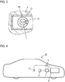
- Fig. 4 shows a motor vehicle 20 having a motor 6 as an electronic drive motor, which is powered by the battery 5, for example, a high-voltage battery.
- a motor 6 as an electronic drive motor, which is powered by the battery 5, for example, a high-voltage battery.
- an electronic device 1 is provided which, as to Fig. 1 is explained, is constructed as with respect to Fig. 2 and 3 has been explained, separate power lines 7 are used for the individual phases of the alternating current.
- the control device 8 data of a plurality of vehicle devices 21, for example, from an accelerator pedal sensor, detected to specify a target power for the engine 6.
- control device 8 In order to set this desired power, the control device 8 detects the currently provided current intensity via the current sensors 9 of the electronic device 1 and, on the other hand, gives pulse widths for the semiconductor switches of the electronic device in order to regulate the actually emitted current intensity to the desired current intensity.
Landscapes
- Physics & Mathematics (AREA)
- General Physics & Mathematics (AREA)
- Engineering & Computer Science (AREA)
- Microelectronics & Electronic Packaging (AREA)
- Power Engineering (AREA)
- Computer Hardware Design (AREA)
- Condensed Matter Physics & Semiconductors (AREA)
- Geometry (AREA)
- Chemical & Material Sciences (AREA)
- Materials Engineering (AREA)
- Mechanical Engineering (AREA)
- Measuring Instrument Details And Bridges, And Automatic Balancing Devices (AREA)
- Inverter Devices (AREA)
Abstract
Elektronikeinrichtung mit wenigstens einer zu kühlenden Komponente (2), einem Kühlelement (4) zur Kühlung der zu kühlenden Komponente (2), wenigstens einer Stromleitung (7) und einem jeweiligen Stromsensor (9) zur Erfassung einer Stromstärke eines durch die jeweilige Stromleitung (7) fließenden Stroms, wobei das Kühlelement (4) eine Ausnehmung (10) aufweist, in die der Stromsensor (9) eingreift oder in der der Stromsensor (9) angeordnet ist.

Description
Die Erfindung betrifft eine Elektronikeinrichtung mit wenigstens einer zu kühlenden Komponente, einem Kühlelement zur Kühlung der zu kühlenden Komponente, wenigstens einer Stromleitung und einem jeweiligen Stromsensor zur Erfassung einer Stromstärke eines durch die jeweilige Stromleitung fließenden Stroms. Daneben betrifft die Erfindung ein Kraftfahrzeug.The invention relates to an electronic device with at least one component to be cooled, a cooling element for cooling the component to be cooled, at least one power line and a respective current sensor for detecting a current strength of a current flowing through the respective power line. In addition, the invention relates to a motor vehicle.
In einer Vielzahl von Anwendungsfällen ist es erforderlich, einer Elektronikeinrichtung zugeführte Ströme bzw. durch diese bereitgestellte Ströme zu überwachen. Beispielsweise soll bei Traktionswechselrichtern in Kraftfahrzeugen typischerweise eine Überwachung und Regelung der bereitgestellten Leistung bzw. Stromstärke erfolgen. Hierzu können Wechselstromsensoren genutzt werden. Als Wechselstromsensoren können beispielsweise Hall-Sensoren genutzt werden. Um eine hohe Empfindlichkeit bei einer möglichst einfachen Beschaltung zu erreichen, können Open-Loop-Hall-Sensoren genutzt werden, die einen Flusskonzentrator, beispielsweise einen um die Leitung geführten Ring aus Weicheisen, aufweisen. Bei einer Open-Loop-Sensorik wird die Hall-Spannung direkt erfasst.In a large number of applications, it is necessary to monitor currents supplied to an electronic device or currents provided by them. For example, in traction inverters in motor vehicles, monitoring and regulation of the provided power or current should typically take place. For this purpose, AC sensors can be used. As AC sensors, for example, Hall sensors can be used. In order to achieve a high sensitivity with the simplest possible wiring, open-loop Hall sensors can be used which have a flux concentrator, for example a ring of soft iron guided around the pipe. In open-loop sensor technology, the Hall voltage is detected directly.
Problematisch ist hierbei, dass entsprechende Hall-Sensoren relativ großbauend sind. Zudem können sich die Komponenten des Hall-Sensors im Betrieb erwärmen, womit potentiell Messfehler auftreten können bzw. die Messgenauigkeit sinkt.The problem here is that corresponding Hall sensors are relatively large construction. In addition, the components of the Hall sensor can heat up during operation, which can potentially lead to measurement errors or the measurement accuracy drops.
Aus der Druckschrift
Der Erfindung liegt somit die Aufgabe zugrunde, eine platzsparende Möglichkeit zur Messung einer Stromstärke in einer Elektronikeinrichtung anzugeben, die insbesondere mit geringer technischer Komplexität umsetzbar ist.The invention is therefore based on the object of specifying a space-saving possibility for measuring a current intensity in an electronic device, which can be implemented in particular with low technical complexity.
Die Aufgabe wird erfindungsgemäß durch eine Elektronikeinrichtung der eingangs genannten Art gelöst, wobei das Kühlelement eine Ausnehmung aufweist, in die der Stromsensor eingreift oder in der der Stromsensor angeordnet ist.The object is achieved by an electronic device of the type mentioned above, wherein the cooling element has a recess into which the current sensor engages or in which the current sensor is arranged.
Erfindungsgemäß wird somit vorgeschlagen, einen Stromsensor zumindest teilweise in ein ohnehin in der Elektronikeinrichtung vorgesehenes Kühlelement zu integrieren. Durch die zumindest teilweise Aufnahme des Stromsensors in dem Kühlelement kann Bauraum eingespart werden. Zugleich resultiert hieraus eine Kühlung des Stromsensors, wodurch potentiell die Baugröße des Stromsensors weiter reduziert werden kann und/oder seine Messempfindlichkeit steigen kann.According to the invention it is thus proposed to integrate a current sensor at least partially into an already provided in the electronic device cooling element. By at least partially receiving the current sensor in the cooling element space can be saved. At the same time, this results in a cooling of the current sensor, whereby potentially the size of the current sensor can be further reduced and / or its sensitivity can increase.
Das Kühlelement kann beispielsweise eine Kühlplatte sein, die dazu dienen kann, elektrische Halbleiterschalter oder andere wärmeerzeugende Komponenten der Elektronikeinrichtung zu kühlen. Die Kühlplatte kann beispielsweise eine Metallplatte sein, die aufgrund ihrer hohen Wärmeleitfähigkeit die Oberfläche zum Abstrahlen von Wärme vergrößert. Es ist jedoch auch möglich, dass das Kühlelement bzw. die Kühlplatte eine aktive Kühlung umfasst. Beispielsweise kann das Kühlelement bzw. die Kühlplatte von Kühlkanälen durchsetzt sein, die von einem Kühlfluid durchströmt werden.The cooling element may for example be a cooling plate, which may serve to cool electrical semiconductor switches or other heat-generating components of the electronic device. The cooling plate may for example be a metal plate, which increases the surface for radiating heat due to its high thermal conductivity. However, it is also possible that the cooling element or the cooling plate comprises an active cooling. For example, the cooling element or the cooling plate can be penetrated by cooling passages through which a cooling fluid flows.
Der Stromsensor kann als vorkonfektioniertes Modul ausgebildet sein, das, insbesondere über ein Gehäuse des Stromsensors, an der Kühlplatte befestigt ist. Der Stromsensor kann mit dem Kühlelement verschraubt, vernietet, verrastet oder verklebt sein. Der Stromsensor kann insbesondere ein Wechselstromsensor sein. Beispielsweise kann ein Hall-Sensor mit Flusskonzentrator genutzt werden. Der Stromsensor kann insbesondere eine Spannung bereitstellen, die von der gemessenen Stromstärke abhängt. Diese kann, insbesondere mithilfe eines Analog-Digital-Wandlers, durch eine Steuereinrichtung erfasst werden.The current sensor can be designed as a prefabricated module, which is fastened to the cooling plate, in particular via a housing of the current sensor. The current sensor can be screwed, riveted, locked or glued to the cooling element. The current sensor may in particular be an alternating current sensor. For example, a Hall sensor with flux concentrator can be used. In particular, the current sensor can provide a voltage which depends on the measured current intensity. This can be detected by a control device, in particular using an analog-to-digital converter.
Die Elektronikeinrichtung kann ein Elektronikmodul sein, das wenigstens einen definierten Anschluss zur Verbindung mit weiteren Komponenten aufweist. Die Komponenten des Elektronikmoduls können insbesondere innerhalb eines Gehäuses angeordnet sein. Die Ausnehmung des Kühlelements kann insbesondere eine Durchbrechung sein.The electronic device may be an electronic module which has at least one defined connection for connection to further components. The components of the electronic module can be arranged in particular within a housing. The recess of the cooling element may in particular be an opening.
Die Stromleitung kann zur Energieversorgung der Elektronikeinrichtung dienen oder über sie kann Energie von der Elektronikeinrichtung an eine andere Komponente bereitgestellt werden. Ist die Elektronikeinrichtung beispielsweise ein Stromwandler, kann der Strom einer oder mehrerer Ausgangsleitungen gemessen werden. Alternativ oder ergänzend ist es jedoch auch möglich, dass die Stromleitung mehrere Komponenten der Elektronikeinrichtung miteinander verbindet.The power line can serve to supply power to the electronic device, or it can be used to provide energy from the electronic device to another component. For example, if the electronic device is a current transformer, the current of one or more output lines can be measured. Alternatively or additionally, however, it is also possible that the power line connects several components of the electronic device together.
Vorzugsweise ist die Stromleitung durch eine Ausnehmung des Stromsensors geführt. Die Strommessung kann insbesondere kontaktlos sein. Die Ausnehmung kann zumindest abschnittsweise von einem Flusskonzentrator des Stromsensors umgeben sein, beispielsweise von einem offenen Weicheisenring. Die Ausnehmung kann insbesondere ein Gehäuse des Stromsensors durchsetzen. Die Stromleitung kann zumindest einseitig mit einem offenen Kontaktbereich enden, der zum Anschluss eines Verbindungsmittels dient. Beispielsweise kann die Stromleitung in einem Stecker oder einer Buchse enden.Preferably, the power line is passed through a recess of the current sensor. The current measurement may in particular be contactless. The recess may be at least partially surrounded by a flux concentrator of the current sensor, for example by an open soft iron ring. The recess can in particular pass through a housing of the current sensor. The power line can end at least on one side with an open contact area, which serves to connect a connecting means. For example, the power line may terminate in a plug or socket.
Die Ausnehmung des Kühlelements kann eine Durchbrechung sein, durch die die Stromleitung hindurchgeführt ist. Insbesondere kann der Stromsensor in der Durchbrechung angeordnet sein und die Stromleitung kann durch den Stromsensor hindurchgeführt sein. Durch das Führen der Stromleitung durch die Durchbrechung kann eine Kühlung der Stromleitung, insbesondere im Bereich des Stromsensors, erreicht werden. Hierdurch kann es möglich sein, eine Stromleitung zu verwenden, die zumindest im Bereich des Stromsensors einen geringeren Leitungsquerschnitt aufweist als er bei einer ungekühlten Leitung erforderlich wäre. Bei einer Nutzung eines kleineren Leitungsquerschnitts kann jedoch zugleich ein Flusskonzentrator mit geringerem Innendurchmesser genutzt werden, wodurch insgesamt ein kleiner bauender Stromsensor realisiert werden kann.The recess of the cooling element may be an opening through which the power line is passed. In particular, the current sensor may be arranged in the opening and the power line may be passed through the current sensor. By guiding the power line through the opening, cooling of the power line, in particular in the area of the current sensor, can be achieved. This makes it possible to use a power line which, at least in the region of the current sensor, has a smaller line cross-section than would be required for an uncooled line. When using a smaller line cross-section, however, a flux concentrator with a smaller inner diameter can be used at the same time, whereby a total of a smaller-sized current sensor can be realized.
Es können mehrere Stromsensoren gemeinsam in der Ausnehmung des Kühlelements angeordnet sein. Die Stromsensoren können insbesondere in einem gemeinsamen Gehäuse angeordnet sein. Hierdurch kann die Elektronikeinrichtung einfacher aufgebaut werden. Werden mehrere Stromsensoren gemeinsam in einer Durchbrechung angeordnet, wobei die Stromleitungen jeweils durch die Stromsensoren geführt sind, kann insbesondere durch Kontaktbereiche der Stromleitungen an einer Seite des Kühlelements ein Verbindungselement, beispielsweise ein Stecker oder eine Buchse, für alle Stromleitungen ausgebildet werden. Hierdurch kann eine Verbindung mehrerer Stromleitungen einfach umgesetzt werden.Several current sensors can be arranged together in the recess of the cooling element. The current sensors can be arranged in particular in a common housing. As a result, the electronic device can be constructed simpler. If a plurality of current sensors are arranged together in an opening, wherein the current lines are each guided by the current sensors, in particular by contact areas of the power lines on one side of the cooling element, a connecting element, for example a plug or a socket, be formed for all power lines. As a result, a connection of multiple power lines can be easily implemented.
Ein Gehäuse, das einen oder mehrere Stromsensoren aufweist, kann derart geformt sein, dass es durch die Ausnehmung des Kühlelements geführt bzw. gehaltert wird. Ist die Ausnehmung eine Durchbrechung, so kann das Gehäuse einen Stützabschnitt aufweisen, der über die Durchbrechung hinausragt, so dass das Gehäuse nach dem Einsetzen in die Durchbrechung mit dem Stützabschnitt auf dem Kühlelement aufliegt. Hierdurch wird eine besonders einfache Montage des Stromsensors bzw. der Stromsensoren erreicht. Der Stützabschnitt kann eine Ausnehmung oder Durchbrechung aufweisen, um beispielsweise eine Schraube oder eine Niete zu führen, mit der der Stromsensor an dem Kühlelement befestigt ist.A housing having one or more current sensors can be shaped such that it is guided or held by the recess of the cooling element. If the recess is an opening, then the housing may have a support section which projects beyond the opening, so that the housing rests on the cooling element after insertion into the opening with the support section. As a result, a particularly simple assembly of the current sensor or the current sensors is achieved. The support portion may include a recess or aperture to guide, for example, a screw or rivet with which the current sensor is attached to the cooling element.
Der Stromsensor kann ein die Stromleitung umgreifendes Flusskonzentrationselement aufweisen, das in Umfangsrichtung eine Öffnung aufweist, in der eine Hall-Sonde angeordnet ist. Das Flusskonzentrationselement kann beispielsweise eine offene Ringform bzw. eine C-Form aufweisen. Hall-Sonden mit Flusskonzentrator sind im Stand der Technik prinzipiell bekannt und sollen nicht detailliert erläutert werden. Bei einer Hall-Sonde wird, zumindest bei Open-Loop-Messungen, ein fester Strom an die Hall-Sonde angelegt und eine im Wesentlichen senkrecht hierzu abfallende Spannung gemessen. Da ein eindeutiger Zusammenhang zwischen dem induzierten Feld und einer geführten Stromstärke und einer an einer Hall-Sonde abfallenden Spannung und einem die Hall-Sonde durchsetzenden Feld vorliegt, kann somit eine Stromstärke in der Stromleitung kontaktlos gemessen werden. Der Zusammenhang zwischen einer an der Hall-Sonde abfallenden Spannung und der Stromstärke kann näherungsweise als linear angenommen werden. Es ist jedoch auch möglich, diesen Zusammenhang vorangehend zu messen und beispielsweise als Wertetabelle in einer die Messdaten der Hall-Sonde erfassenden Steuereinrichtung abzulegen.The current sensor may comprise a flux concentrating element encompassing the power line, which has an opening in the circumferential direction in which a Hall probe is arranged. The flux concentration element may, for example, have an open ring shape or a C shape. Hall probes with flux concentrator are known in principle in the prior art and will not be explained in detail. In the case of a Hall probe, at least in open-loop measurements, a fixed current is applied to the Hall probe and a voltage which drops substantially perpendicular thereto is measured. Since there is a clear relationship between the induced field and a guided current and a voltage drop across a Hall probe and a field passing through the Hall probe, a current in the power line can thus be measured without contact. The relationship between a voltage drop across the Hall probe and the current can be approximated as linear. However, it is also possible to measure this relationship beforehand and store it, for example, as a value table in a control device which detects the measurement data of the Hall probe.
Das Flusskonzentrationselement kann beispielsweise aus Weicheisen oder einem anderen paramagnetischen bzw. weichmagnetischen Material bestehen. Das Flusskonzentrationselement und/oder die Hall-Sonde können zumindest teilweise, vorzugsweise vollständig, innerhalb der Ausnehmung des Kühlelements liegen. Durch eine Kühlung der Hall-Sonde und/oder des Flusskonzentrationselements kann die Empfindlichkeit der Hall-Sonde verbessert werden und es kann insgesamt ein kleiner bauender Stromsensor realisiert werden.The flux concentration element may for example consist of soft iron or another paramagnetic or soft magnetic material. The flux concentration element and / or the Hall probe may be at least partially, preferably completely, within the recess of the cooling element. By cooling the Hall probe and / or the flux concentration element, the sensitivity of the Hall probe can be improved and it can be realized on the whole a smaller-sized current sensor.
Die Elektronikeinrichtung kann ein Stromrichter sein oder einen Stromrichter umfassen. Sie kann insbesondere ein Wechselrichter, insbesondere für einen elektrischen Motor, beispielsweise einen Antriebsmotor eines Kraftfahrzeugs, sein.The electronic device may be a power converter or comprise a power converter. In particular, it can be an inverter, in particular for an electric motor, for example a drive motor of a motor vehicle.
Die zu kühlende Komponente oder wenigstens eine der zu kühlenden Komponenten kann ein Halbleiterschalter sein. Der Halbleiterschalter kann ein Transistor, beispielsweise ein IGBT oder ein Mosfet, sein. Schaltungen zum Umrichten von Strömen mithilfe von Halbleiterschaltern sind im Stand der Technik bekannt und sollen daher nicht erläutert werden. Gegenüber beispielsweise Relais erlauben Halbleiterschalter deutlich kürzere Schaltintervalle. Mittlerweile können Halbleiterschalter realisiert werden, die bei einem geschlossenen Schalter einen sehr geringen Widerstand aufweisen. Dennoch fällt, insbesondere bei einer Richtung von Hochströmen, wie sie beispielsweise für Antriebsmotoren erforderlich sind, eine gewisse Verlustleistung am Halbleiterschalter ab, wodurch entsprechende Schaltungen typischerweise gekühlt werden. Ein hierfür notwendiges Kühlelement kann in der erfindungsgemäßen Elektronikeinrichtung gleichzeitig zur Aufnahme und zur Kühlung des Stromsensors genutzt werden.The component to be cooled or at least one of the components to be cooled may be a semiconductor switch. The semiconductor switch may be a transistor, for example an IGBT or a mosfet. Circuits for converting currents by means of semiconductor switches are known in the art and therefore will not be explained. Compared with, for example, relays, semiconductor switches allow significantly shorter switching intervals. Meanwhile, semiconductor switches can be realized, which have a very low resistance in a closed switch. Nevertheless, in particular in a direction of high currents, as required, for example, for drive motors, a certain power dissipation from the semiconductor switch, whereby corresponding circuits are typically cooled. A cooling element necessary for this purpose can be used simultaneously in the electronic device according to the invention for receiving and for cooling the current sensor.
Das Kühlelement kann zumindest im Bereich der Ausnehmung aus Metall bestehen. Ein Kühlelement aus Metall, insbesondere eine Kühlplatte, weist eine gute Wärmeleitfähigkeit auf und kann somit dazu dienen, eine Oberfläche, über die Wärme abgestrahlt werden kann, zu vergrößern. Wie bereits erläutert kann es vorteilhaft sein, zusätzlich eine aktive Kühlung vorzusehen, wobei beispielsweise Kühlfluid durch Kühlkanäle des Kühlelements geführt werden kann. Die zumindest bereichsweise Ausbildung des Kühlelements aus Metall verbessert die elektromagnetische Abschirmung des Stromsensors gegenüber externen Einflüssen. Dies kann dazu dienen, die Messgenauigkeit weiter zu erhöhen. Alternativ oder ergänzend kann aufgrund der verbesserten elektromagnetischen Abschirmung auch ein kleiner bauender Stromsensor realisiert werden.The cooling element may be made of metal at least in the region of the recess. A cooling element made of metal, in particular a cooling plate, has a good thermal conductivity and can thus serve to increase a surface through which heat can be radiated. As already explained, it can be advantageous to additionally provide active cooling, wherein, for example, cooling fluid can be passed through cooling passages of the cooling element. The at least partially forming the cooling element made of metal improves the electromagnetic shielding of the current sensor against external influences. This can serve to further increase the measurement accuracy. Alternatively or additionally, a smaller current sensor can be realized due to the improved electromagnetic shielding.
Neben der erfindungsgemäßen Elektronikeinrichtung betrifft die Erfindung ein Kraftfahrzeug, das eine erfindungsgemäße Elektronikeinrichtung umfasst. Die Elektronikeinrichtung kann insbesondere als Wechselrichter für einen Motor des Kraftfahrzeugs, speziell einen Antriebsmotor des Kraftfahrzeugs, verwendet werden.In addition to the electronic device according to the invention, the invention relates to a motor vehicle comprising an electronic device according to the invention. The electronic device can be used in particular as an inverter for an engine of the motor vehicle, especially a drive motor of the motor vehicle.
Vorzugsweise umfasst das Kraftfahrzeug eine Steuereinrichtung, durch die die dem Motor zugeführte Leistung geregelt wird, wobei wenigstens einer der Stromsensoren einen an den Motor bereitgestellten Strom erfasst, wobei ein Sensorsignal dieses Sensors als Eingangsgröße einer Leistungsregelung nutzbar ist. Die Regelung kann, beispielsweise durch eine Pulsweitensteuerung der bei der Wechselrichtung genutzten Halbleiterschaltern, den Strom auf einen Sollwert regeln.Preferably, the motor vehicle comprises a control device, by means of which the power supplied to the motor is regulated, wherein at least one of the current sensors detects a current supplied to the motor, wherein a sensor signal of this sensor is usable as an input variable of a power control. The control can regulate the current to a desired value, for example by a pulse width control of the semiconductor switches used in the direction of change.
Weitere Vorteile und Einzelheiten der Erfindung ergeben sich aus den folgenden Ausführungsbeispielen sowie den zugehörigen Zeichnungen. Hierbei zeigen schematisch:
- Fig. 1
- ein Ausführungsbeispiel einer erfindungsgemäßen Elektronikeinrichtung,
- Fig. 2 und 3
- Detailansichten eines weiteren Ausführungsbeispiels einer erfindungsgemäßen Elektronikeinrichtung, und
- Fig.4
- ein Ausführungsbeispiel eines erfindungsgemäßen Kraftfahrzeugs.
- Fig. 1
- An embodiment of an electronic device according to the invention,
- FIGS. 2 and 3
- Detailed views of another embodiment of an electronic device according to the invention, and
- Figure 4
- An embodiment of a motor vehicle according to the invention.
Die zu kühlenden Komponenten 2 können insbesondere Halbleiterschalter sein, die zur Umrichtung des Stroms genutzt werden. Hierzu können entsprechende Schaltsignale bzw. Pulsweiten und Phasenlagen durch eine Steuereinrichtung 8 vorgegeben werden. Das Kühlelement 4 kann eine Kühlplatte sein, die beispielsweise als Metallplatte ausgebildet sein kann. Optional könnten in dem Kühlelement 4 Kühlkanäle vorgesehen werden, durch die ein Kühlfluid geführt werden kann, um die Kühlung der zu kühlenden Komponente 2 weiter zu verbessern.The
Um den über die Stromleitung 7 bereitgestellten Strom auf einen Sollwert zu regeln, soll durch die Steuereinrichtung 8 ein Ist-Wert des Stromes ermittelt werden. Hierzu weist die Elektronikeinrichtung 1 einen Stromsensor 9 auf, der in einer Ausnehmung 10, nämlich einer Durchbrechung, des Kühlelements 4 angeordnet ist. Der Aufbau des Stromsensors 9 wird später noch im Detail mit Bezug auf
Das Stromkabel 7 ist durch eine Ausnehmung 11, nämlich eine Durchbrechung, des Stromsensors 9 geführt, um eine kontaktlose Messung des Stroms zu ermöglichen.The
Der gezeigte Aufbau der Elektronikeinrichtung 1 ermöglicht durch die Anordnung des Stromsensors 9 in der Kühleinrichtung 4 eine Integration einer Strommessung bei einem geringen Bauraumverbrauch. Da zudem sowohl der Stromsensor 9 als auch die Stromleitung 7 im Bereich des Stromsensors 9 durch das Kühlelement 4 mitgekühlt werden, kann die Messgenauigkeit des Stromsensors 9 verbessert werden und der Leitungsquerschnitt der Stromleitung 7 kann verringert werden, wodurch auch die Nutzung eines kompakteren Stromsensors 9 ermöglicht wird.The construction shown of the
In der Ausnehmung 10 des Kühlelements 4 sind drei Stromsensoren 9 für die drei Stromleitungen 7 angeordnet. Diese sind über ein gemeinsames Gehäuse 12 an dem Kühlelement 4 befestigt. Das Gehäuse 12 kann in
Die einzelnen Stromsensoren 9 werden durch ein die Stromleitung 7 umgreifendes Flusskonzentrationselement 15 und eine Hall-Sonde 16 gebildet, wobei das Flusskonzentrationselement 15 in Umfangsrichtung eine Öffnung aufweist, in der die Hall-Sonde 16 angeordnet ist. Die Verdrahtung der Hall-Sonde 16 ist aus Übersichtlichkeitsgründen nicht dargestellt. Die Abschnitte 17 der Stromleitungen 7, in denen diese das Kühlelement 4 und den Stromsensor 9 durchqueren, weisen einen verengten Querschnitt auf. Dies wird dadurch ermöglicht, dass die Stromleitung 7 in diesem Bereich 17 jeweils durch das Kühlelement 4 gekühlt wird, wodurch die Stromtragefähigkeit verbessert wird. Dies ermöglicht es, dass auch die Ausnehmung 11 des Stromsensors 9 bzw. des Flusskonzentrationselements 15 einen kleineren Durchmesser aufweist, als er anderenfalls erforderlich wäre, womit der Stromsensor 9 insgesamt kompakter aufgebaut werden kann.The individual
Die Stromleitungen 7 weisen einseitig offene Kontakte 19 auf, durch die ein Stecker 18 im Bereich des Kühlelements gebildet wird. An diesen kann über ein entsprechendes Verbindungselement beispielsweise der Motor 6 angeschlossen werden.The
Ist das Kühlelement 4 zumindest im Bereich der Ausnehmung 10 aus Metall gebildet, so kann das Kühlelement 4 zugleich zur elektromagnetischen Abschirmung des Stromsensors 9 dienen, womit dessen Messgenauigkeit verbessert werden kann.If the
Claims (10)
dadurch gekennzeichnet,
dass das Kühlelement (4) eine Ausnehmung (10) aufweist, in die der Stromsensor (9) eingreift oder in der der Stromsensor (9) angeordnet ist.Electronic device comprising at least one component (2) to be cooled, a cooling element (4) for cooling the component (2) to be cooled, at least one power line (7) and a respective current sensor (9) for detecting a current strength through the respective power line (7 ) flowing stream,
characterized,
that the cooling element (4) has a recess (10) which is engaged by the current sensor (9) or in which the current sensor (9) is arranged.
dadurch gekennzeichnet,
dass die Stromleitung (7) durch eine Ausnehmung (11) des Stromsensors (9) geführt ist.Electronic device according to claim 1,
characterized,
that the power line (7) through a recess (11) of the current sensor (9) is guided.
dadurch gekennzeichnet,
dass die Ausnehmung (10) des Kühlelements (4) eine Durchbrechung ist, durch die die Stromleitung (7) hindurch geführt ist.Electronic device according to claim 1 or 2,
characterized,
that the recess (10) of the cooling element (4) is a perforation is through the power line (7) guided.
dadurch gekennzeichnet,
dass mehrere der Stromsensoren (9) gemeinsam in der Ausnehmung (10) des Kühlelements (4) angeordnet sind.Electronic device according to one of the preceding claims,
characterized,
in that a plurality of the current sensors (9) are arranged together in the recess (10) of the cooling element (4).
dadurch gekennzeichnet,
dass die Stromsensoren (9) in einem gemeinsamen Gehäuse (12) angeordnet sind.Electronic device according to claim 4,
characterized,
in that the current sensors (9) are arranged in a common housing (12).
dadurch gekennzeichnet,
dass der Stromsensor (9) ein die Stromleitung (7) umgreifendes Flusskonzentrationselement (15) aufweist, das in Umfangsrichtung eine Öffnung aufweist, in der eine Hallsonde (16) angeordnet ist.Electronic device according to one of the preceding claims,
characterized,
in that the current sensor (9) has a flux concentration element (15) encompassing the power line (7), which has an opening in the circumferential direction in which a Hall probe (16) is arranged.
dadurch gekennzeichnet,
dass sie ein Stromrichter ist oder einen Stromrichter umfasst.Electronic device according to one of the preceding claims,
characterized,
that it is a power converter or includes a power converter.
dadurch gekennzeichnet,
dass die zu kühlende Komponente (2) oder wenigstens eine der zu kühlenden Komponenten (2) ein Halbleiterschalter ist.Electronic device according to claim 7,
characterized,
that the component to be cooled (2) or at least one of the components to be cooled (2) is a semiconductor switch.
dadurch gekennzeichnet,
dass das Kühlelement (4) zumindest im Bereich der Ausnehmung (10) aus Metall besteht.Electronic device according to one of the preceding claims,
characterized,
that the cooling element (4) at least in the region of the recess (10) consists of metal.
dadurch gekennzeichnet,
dass es eine Elektronikeinrichtung (1) nach einem der vorangehenden Ansprüche umfasst.Motor vehicle,
characterized,
in that it comprises an electronic device (1) according to one of the preceding claims.
Applications Claiming Priority (1)
| Application Number | Priority Date | Filing Date | Title |
|---|---|---|---|
| DE102017212434.2A DE102017212434A1 (en) | 2017-07-20 | 2017-07-20 | Electronic device with at least one component to be cooled |
Publications (1)
| Publication Number | Publication Date |
|---|---|
| EP3432006A1 true EP3432006A1 (en) | 2019-01-23 |
Family
ID=62143061
Family Applications (1)
| Application Number | Title | Priority Date | Filing Date |
|---|---|---|---|
| EP18171375.1A Pending EP3432006A1 (en) | 2017-07-20 | 2018-05-09 | Electronics device with current sensor integrated into a heat sink |
Country Status (4)
| Country | Link |
|---|---|
| US (1) | US10784180B2 (en) |
| EP (1) | EP3432006A1 (en) |
| CN (1) | CN109283376B (en) |
| DE (1) | DE102017212434A1 (en) |
Cited By (1)
| Publication number | Priority date | Publication date | Assignee | Title |
|---|---|---|---|---|
| WO2023213346A1 (en) * | 2022-05-06 | 2023-11-09 | Fachhochschule Kiel | Power semiconductor module having a plug-in connection |
Citations (7)
| Publication number | Priority date | Publication date | Assignee | Title |
|---|---|---|---|---|
| WO1994027157A1 (en) * | 1993-05-11 | 1994-11-24 | Abb Strömberg Kojeet Oy | Current measurement transducer based on magnetic flux density measurement |
| US20060255793A1 (en) * | 2005-05-12 | 2006-11-16 | Michel Montreuil | Current sensor |
| US20080048642A1 (en) * | 2006-08-25 | 2008-02-28 | Denso Corporation | Current sensor |
| EP2261973A2 (en) * | 2009-06-09 | 2010-12-15 | SEMIKRON Elektronik GmbH & Co. KG | High power electronics system |
| DE102015202770A1 (en) * | 2015-02-16 | 2016-08-18 | Schaeffler Technologies AG & Co. KG | Device for integrated current measurement within a high-voltage contacting of a hybrid module and hybrid module with the device |
| DE102015111204A1 (en) * | 2015-07-10 | 2017-01-12 | Semikron Elektronik Gmbh & Co. Kg | Power electronic module with load connection elements |
| EP3236724A1 (en) * | 2016-04-18 | 2017-10-25 | SEMIKRON Elektronik GmbH & Co. KG | Power electronics assembly and vehicles with same |
Family Cites Families (12)
| Publication number | Priority date | Publication date | Assignee | Title |
|---|---|---|---|---|
| US6426617B1 (en) * | 1999-09-28 | 2002-07-30 | Rockwell Automation Technologies, Inc. | Hall effect current sensor system packaging |
| FR2839417B1 (en) * | 2002-05-03 | 2004-07-16 | Dav | COOLED POWER SWITCHING DEVICE |
| DE102004054317B4 (en) | 2004-11-10 | 2014-05-15 | Mitsubishi Denki K.K. | Current measuring device |
| JP5975596B2 (en) | 2010-08-05 | 2016-08-23 | 矢崎総業株式会社 | Current sensor structure |
| CH703903B1 (en) | 2010-10-01 | 2014-04-30 | Melexis Tessenderlo Nv | Current sensor. |
| JP5806134B2 (en) | 2012-01-23 | 2015-11-10 | トヨタ自動車株式会社 | Power converter |
| DE102012206271A1 (en) * | 2012-04-17 | 2013-10-17 | Semikron Elektronik Gmbh & Co. Kg | Liquid-cooled arrangement with storable power semiconductor modules and at least one capacitor device and power semiconductor module for this purpose |
| US20140091808A1 (en) * | 2012-09-28 | 2014-04-03 | Arc Suppression Technologies | Contact separation detector and methods therefor |
| CA2926271C (en) * | 2015-04-06 | 2022-04-12 | Zonge International, Inc. | Circuits and methods for monitoring current in geophysical survey systems |
| US10128723B2 (en) * | 2015-07-07 | 2018-11-13 | Milwaukee Electric Tool Corporation | Printed circuit board spacer |
| JP2018004269A (en) * | 2016-06-27 | 2018-01-11 | アイシン精機株式会社 | Current sensor |
| JP6503413B2 (en) * | 2017-05-31 | 2019-04-17 | 本田技研工業株式会社 | DC / DC converter and electrical equipment |
-
2017
- 2017-07-20 DE DE102017212434.2A patent/DE102017212434A1/en active Pending
-
2018
- 2018-05-09 EP EP18171375.1A patent/EP3432006A1/en active Pending
- 2018-05-30 US US15/992,469 patent/US10784180B2/en active Active
- 2018-07-19 CN CN201810798050.7A patent/CN109283376B/en active Active
Patent Citations (7)
| Publication number | Priority date | Publication date | Assignee | Title |
|---|---|---|---|---|
| WO1994027157A1 (en) * | 1993-05-11 | 1994-11-24 | Abb Strömberg Kojeet Oy | Current measurement transducer based on magnetic flux density measurement |
| US20060255793A1 (en) * | 2005-05-12 | 2006-11-16 | Michel Montreuil | Current sensor |
| US20080048642A1 (en) * | 2006-08-25 | 2008-02-28 | Denso Corporation | Current sensor |
| EP2261973A2 (en) * | 2009-06-09 | 2010-12-15 | SEMIKRON Elektronik GmbH & Co. KG | High power electronics system |
| DE102015202770A1 (en) * | 2015-02-16 | 2016-08-18 | Schaeffler Technologies AG & Co. KG | Device for integrated current measurement within a high-voltage contacting of a hybrid module and hybrid module with the device |
| DE102015111204A1 (en) * | 2015-07-10 | 2017-01-12 | Semikron Elektronik Gmbh & Co. Kg | Power electronic module with load connection elements |
| EP3236724A1 (en) * | 2016-04-18 | 2017-10-25 | SEMIKRON Elektronik GmbH & Co. KG | Power electronics assembly and vehicles with same |
Cited By (1)
| Publication number | Priority date | Publication date | Assignee | Title |
|---|---|---|---|---|
| WO2023213346A1 (en) * | 2022-05-06 | 2023-11-09 | Fachhochschule Kiel | Power semiconductor module having a plug-in connection |
Also Published As
| Publication number | Publication date |
|---|---|
| CN109283376B (en) | 2021-08-17 |
| DE102017212434A1 (en) | 2019-01-24 |
| US10784180B2 (en) | 2020-09-22 |
| CN109283376A (en) | 2019-01-29 |
| US20190027420A1 (en) | 2019-01-24 |
Similar Documents
| Publication | Publication Date | Title |
|---|---|---|
| DE102010044509A1 (en) | inverter | |
| EP3076195B1 (en) | Circuit assembly for cable checking, cable testing, cable diagnosis and/or the localization of faults in cables, and an instrument incorporating such a circuit assembly | |
| DE102010000082B4 (en) | Circuit arrangement of electronic circuit breakers of a power generating device | |
| DE102018130954A1 (en) | CURRENT SENSOR | |
| EP2794334A1 (en) | Control device for semiconductor switch on an inverter and method for the actuation of an inverter | |
| EP2250509A2 (en) | Current measuring device using a magnetically sensitive sensor for a power electronics system | |
| DE102019003373A1 (en) | Power semiconductor device with integrated current measurement | |
| EP1028321A2 (en) | Voltage devider for measuring transformer | |
| EP3432006A1 (en) | Electronics device with current sensor integrated into a heat sink | |
| DE102014208255B4 (en) | Circuit arrangement, current transformer with a circuit arrangement | |
| DE102010036040A1 (en) | Device for measuring electric current in current guard of power-electronic arrangement for industrial truck, has current guard, circuit board and magnetic field sensor that are arranged based on surface mount device construction | |
| DE102004054317B4 (en) | Current measuring device | |
| WO2006125407A1 (en) | Device for measuring current intensity | |
| WO2013045241A1 (en) | Circuit structure for controlling a jfet component | |
| DE102017222016A1 (en) | Connecting device for connecting a busbar of a semiconductor module with a further busbar, power electronics device with a connecting device and method for producing a power electronic device | |
| DE102020208167A1 (en) | Power module for operating an electric vehicle drive with improved temperature determination of the power semiconductors | |
| DE102017221551A1 (en) | current sensor | |
| AT523610B1 (en) | converter assembly | |
| DE102013213348A1 (en) | Power semiconductor module and electric drive with a power semiconductor module | |
| EP3200225A2 (en) | Electronic module with a power semiconductor assembly | |
| DE102020106447B4 (en) | Arrangement for current measurement | |
| DE102010053392A1 (en) | Tub-shaped power semiconductor module for circuit device utilized in electrical system of e.g. electric vehicle, has multiple power terminals and control and auxiliary terminal arranged on tub walls | |
| DE102016218703B4 (en) | Electricity control device and manufacturing method for power control device | |
| DE102016113055B3 (en) | Arrangement for current measurement on a current feedthrough | |
| DE102019212084B4 (en) | Converter for an electrical machine |
Legal Events
| Date | Code | Title | Description |
|---|---|---|---|
| PUAI | Public reference made under article 153(3) epc to a published international application that has entered the european phase |
Free format text: ORIGINAL CODE: 0009012 |
|
| STAA | Information on the status of an ep patent application or granted ep patent |
Free format text: STATUS: THE APPLICATION HAS BEEN PUBLISHED |
|
| AK | Designated contracting states |
Kind code of ref document: A1 Designated state(s): AL AT BE BG CH CY CZ DE DK EE ES FI FR GB GR HR HU IE IS IT LI LT LU LV MC MK MT NL NO PL PT RO RS SE SI SK SM TR |
|
| AX | Request for extension of the european patent |
Extension state: BA ME |
|
| STAA | Information on the status of an ep patent application or granted ep patent |
Free format text: STATUS: REQUEST FOR EXAMINATION WAS MADE |
|
| 17P | Request for examination filed |
Effective date: 20190723 |
|
| RBV | Designated contracting states (corrected) |
Designated state(s): AL AT BE BG CH CY CZ DE DK EE ES FI FR GB GR HR HU IE IS IT LI LT LU LV MC MK MT NL NO PL PT RO RS SE SI SK SM TR |
|
| STAA | Information on the status of an ep patent application or granted ep patent |
Free format text: STATUS: EXAMINATION IS IN PROGRESS |
|
| 17Q | First examination report despatched |
Effective date: 20220224 |
|
| P01 | Opt-out of the competence of the unified patent court (upc) registered |
Effective date: 20230529 |