EP3431951A1 - Abnormality determination device and abnormality determination method - Google Patents
Abnormality determination device and abnormality determination method Download PDFInfo
- Publication number
- EP3431951A1 EP3431951A1 EP16894593.9A EP16894593A EP3431951A1 EP 3431951 A1 EP3431951 A1 EP 3431951A1 EP 16894593 A EP16894593 A EP 16894593A EP 3431951 A1 EP3431951 A1 EP 3431951A1
- Authority
- EP
- European Patent Office
- Prior art keywords
- inducer
- lifetime
- damage degree
- fatigue
- accumulated
- Prior art date
- Legal status (The legal status is an assumption and is not a legal conclusion. Google has not performed a legal analysis and makes no representation as to the accuracy of the status listed.)
- Granted
Links
Images





Classifications
-
- G—PHYSICS
- G01—MEASURING; TESTING
- G01L—MEASURING FORCE, STRESS, TORQUE, WORK, MECHANICAL POWER, MECHANICAL EFFICIENCY, OR FLUID PRESSURE
- G01L7/00—Measuring the steady or quasi-steady pressure of a fluid or a fluent solid material by mechanical or fluid pressure-sensitive elements
- G01L7/18—Measuring the steady or quasi-steady pressure of a fluid or a fluent solid material by mechanical or fluid pressure-sensitive elements using liquid as the pressure-sensitive medium, e.g. liquid-column gauges
-
- F—MECHANICAL ENGINEERING; LIGHTING; HEATING; WEAPONS; BLASTING
- F04—POSITIVE - DISPLACEMENT MACHINES FOR LIQUIDS; PUMPS FOR LIQUIDS OR ELASTIC FLUIDS
- F04D—NON-POSITIVE-DISPLACEMENT PUMPS
- F04D29/00—Details, component parts, or accessories
- F04D29/18—Rotors
- F04D29/22—Rotors specially for centrifugal pumps
- F04D29/2261—Rotors specially for centrifugal pumps with special measures
- F04D29/2277—Rotors specially for centrifugal pumps with special measures for increasing NPSH or dealing with liquids near boiling-point
-
- F—MECHANICAL ENGINEERING; LIGHTING; HEATING; WEAPONS; BLASTING
- F02—COMBUSTION ENGINES; HOT-GAS OR COMBUSTION-PRODUCT ENGINE PLANTS
- F02K—JET-PROPULSION PLANTS
- F02K9/00—Rocket-engine plants, i.e. plants carrying both fuel and oxidant therefor; Control thereof
- F02K9/42—Rocket-engine plants, i.e. plants carrying both fuel and oxidant therefor; Control thereof using liquid or gaseous propellants
- F02K9/44—Feeding propellants
- F02K9/46—Feeding propellants using pumps
-
- F—MECHANICAL ENGINEERING; LIGHTING; HEATING; WEAPONS; BLASTING
- F02—COMBUSTION ENGINES; HOT-GAS OR COMBUSTION-PRODUCT ENGINE PLANTS
- F02K—JET-PROPULSION PLANTS
- F02K9/00—Rocket-engine plants, i.e. plants carrying both fuel and oxidant therefor; Control thereof
- F02K9/42—Rocket-engine plants, i.e. plants carrying both fuel and oxidant therefor; Control thereof using liquid or gaseous propellants
- F02K9/44—Feeding propellants
- F02K9/50—Feeding propellants using pressurised fluid to pressurise the propellants
-
- F—MECHANICAL ENGINEERING; LIGHTING; HEATING; WEAPONS; BLASTING
- F02—COMBUSTION ENGINES; HOT-GAS OR COMBUSTION-PRODUCT ENGINE PLANTS
- F02K—JET-PROPULSION PLANTS
- F02K9/00—Rocket-engine plants, i.e. plants carrying both fuel and oxidant therefor; Control thereof
- F02K9/42—Rocket-engine plants, i.e. plants carrying both fuel and oxidant therefor; Control thereof using liquid or gaseous propellants
- F02K9/44—Feeding propellants
- F02K9/52—Injectors
-
- F—MECHANICAL ENGINEERING; LIGHTING; HEATING; WEAPONS; BLASTING
- F04—POSITIVE - DISPLACEMENT MACHINES FOR LIQUIDS; PUMPS FOR LIQUIDS OR ELASTIC FLUIDS
- F04D—NON-POSITIVE-DISPLACEMENT PUMPS
- F04D15/00—Control, e.g. regulation, of pumps, pumping installations or systems
- F04D15/0088—Testing machines
-
- F—MECHANICAL ENGINEERING; LIGHTING; HEATING; WEAPONS; BLASTING
- F04—POSITIVE - DISPLACEMENT MACHINES FOR LIQUIDS; PUMPS FOR LIQUIDS OR ELASTIC FLUIDS
- F04D—NON-POSITIVE-DISPLACEMENT PUMPS
- F04D29/00—Details, component parts, or accessories
- F04D29/18—Rotors
-
- G—PHYSICS
- G01—MEASURING; TESTING
- G01L—MEASURING FORCE, STRESS, TORQUE, WORK, MECHANICAL POWER, MECHANICAL EFFICIENCY, OR FLUID PRESSURE
- G01L27/00—Testing or calibrating of apparatus for measuring fluid pressure
- G01L27/02—Testing or calibrating of apparatus for measuring fluid pressure of indicators
-
- G—PHYSICS
- G01—MEASURING; TESTING
- G01M—TESTING STATIC OR DYNAMIC BALANCE OF MACHINES OR STRUCTURES; TESTING OF STRUCTURES OR APPARATUS, NOT OTHERWISE PROVIDED FOR
- G01M13/00—Testing of machine parts
-
- G—PHYSICS
- G01—MEASURING; TESTING
- G01M—TESTING STATIC OR DYNAMIC BALANCE OF MACHINES OR STRUCTURES; TESTING OF STRUCTURES OR APPARATUS, NOT OTHERWISE PROVIDED FOR
- G01M5/00—Investigating the elasticity of structures, e.g. deflection of bridges or air-craft wings
-
- G—PHYSICS
- G01—MEASURING; TESTING
- G01M—TESTING STATIC OR DYNAMIC BALANCE OF MACHINES OR STRUCTURES; TESTING OF STRUCTURES OR APPARATUS, NOT OTHERWISE PROVIDED FOR
- G01M99/00—Subject matter not provided for in other groups of this subclass
-
- G—PHYSICS
- G05—CONTROLLING; REGULATING
- G05B—CONTROL OR REGULATING SYSTEMS IN GENERAL; FUNCTIONAL ELEMENTS OF SUCH SYSTEMS; MONITORING OR TESTING ARRANGEMENTS FOR SUCH SYSTEMS OR ELEMENTS
- G05B23/00—Testing or monitoring of control systems or parts thereof
- G05B23/02—Electric testing or monitoring
- G05B23/0205—Electric testing or monitoring by means of a monitoring system capable of detecting and responding to faults
- G05B23/0259—Electric testing or monitoring by means of a monitoring system capable of detecting and responding to faults characterized by the response to fault detection
- G05B23/0283—Predictive maintenance, e.g. involving the monitoring of a system and, based on the monitoring results, taking decisions on the maintenance schedule of the monitored system; Estimating remaining useful life [RUL]
-
- F—MECHANICAL ENGINEERING; LIGHTING; HEATING; WEAPONS; BLASTING
- F05—INDEXING SCHEMES RELATING TO ENGINES OR PUMPS IN VARIOUS SUBCLASSES OF CLASSES F01-F04
- F05D—INDEXING SCHEME FOR ASPECTS RELATING TO NON-POSITIVE-DISPLACEMENT MACHINES OR ENGINES, GAS-TURBINES OR JET-PROPULSION PLANTS
- F05D2260/00—Function
- F05D2260/82—Forecasts
- F05D2260/821—Parameter estimation or prediction
Definitions
- the present disclosure relates to an abnormality determination device and an abnormality determination method.
- Patent Literature 1 discloses a system for diagnosing a fatigue-damage degree of a vehicle to warn that the lifetime of a front side member is coming to the end by calculating the fatigue-damage degree of the front side member based on an input detected by a sensor.
- Patent Literature 1 Japanese Unexamined Patent Publication No. 2013-79920
- a safety measure may be taken by destroying the airframe.
- destroying the airframe is not acceptable. For this reason, it is required to detect an abnormality before the inducer is damaged and to safely stop the operation.
- a use time for which an inducer is used in one flight is predetermined, and it is possible to safely operate unless the accumulated fatigue-damage degree of the inducer reaches the end of the lifetime of the inducer during the use time.
- the damage is accumulated in an inducer of a flying object due to various factors. For example, in the inducer, minute cavitation occurs randomly in a normal operation state, and this excitation force generates stress, which can lead to destruction of the inducer. In this manner, damage is not always accumulated at a certain rate.
- the warning threshold is preset, warning cannot be made at an appropriate timing if the accumulation speed of the fatigue-damage degree changes.
- the inducer can be determined to be abnormal according to the setting of the warning threshold. In this manner, it is desired to improve the accuracy of abnormality determination of a component (inducer) used only for a predetermined use time per operation.
- An abnormality determination device is a device that determines an abnormality of an inducer used for a pump.
- the abnormality determination device includes a stress-response acquisition unit that acquires a stress response indicating a temporal change in stress applied to the inducer, an accumulated-fatigue-damage-degree calculation unit that calculates an accumulated fatigue-damage degree of the inducer based on the stress response, a lifetime-consumption-rate calculation unit that calculates a lifetime consumption rate that is a changing rate of the accumulated fatigue-damage degree with respect to time, and a determination unit that determines an abnormality of the inducer based on the accumulated fatigue-damage degree and the lifetime consumption rate.
- the inducer is used only for a predetermined use time per operation of the pump.
- An abnormality determination device is a device that determines an abnormality of an inducer used for a pump.
- the abnormality determination device includes a stress-response acquisition unit that acquires a stress response indicating a temporal change in stress applied to the inducer, an accumulated-fatigue-damage-degree calculation unit that calculates an accumulated fatigue-damage degree of the inducer based on the stress response, a lifetime-consumption-rate calculation unit that calculates a lifetime consumption rate that is a changing rate of the accumulated fatigue-damage degree with respect to time, and a determination unit that determines an abnormality of the inducer based on the accumulated fatigue-damage degree and the lifetime consumption rate.
- the inducer is used only for a predetermined use time per operation of the pump.
- An abnormality determination method is an abnormality determination method performed by an abnormality determination device that determines an abnormality of an inducer used for a pump.
- the abnormality determination method includes the steps of acquiring a stress response indicating a temporal change in stress applied to the inducer, calculating an accumulated fatigue-damage degree of the inducer based on the stress response, calculating a lifetime consumption rate that is a changing rate of the accumulated fatigue-damage degree with respect to time, and determining an abnormality of the inducer based on the accumulated fatigue-damage degree and the lifetime consumption rate.
- the inducer is used only for a predetermined use time per operation of the pump.
- the accumulated fatigue-damage degree of the inducer is calculated based on the stress response applied to the inducer, and the lifetime consumption rate that is a changing rate of the accumulated fatigue-damage degree with respect to time is calculated. Then, based on the accumulated fatigue-damage degree and the lifetime consumption rate, an abnormality of the inducer is determined. In this manner, by taking not only the accumulated fatigue-damage degree but also the lifetime consumption rate into consideration, it is possible to determine an abnormality of the inducer according to the accumulation speed (lifetime consumption rate) of the accumulated fatigue-damage degree. As a result, it is possible to improve the accuracy of abnormality determination of the inducer.
- the abnormality determination device may further include a pressure acquisition unit that acquires pressure at an input side of the inducer.
- the stress-response acquisition unit may acquire the stress response based on a pressure response indicating a temporal change in the pressure. In this case, when the stress applied to the inducer cannot be directly measured, it is possible to indirectly acquire the stress response of the stress applied to the inducer by measuring the pressure at the input side of the inducer.
- the determination unit may predict, based on the accumulated fatigue-damage degree and the lifetime consumption rate, whether the accumulated fatigue-damage degree exceeds a lifetime limit defining a limit of a damage degree of the inducer during the operation, and may determine that the inducer is abnormal when predicting that the accumulated fatigue-damage degree exceeds the lifetime limit during the operation. If the accumulated fatigue-damage degree exceeds the lifetime limit of the inducer during the operation, the inducer can be damaged. Thus, when it is predicted that the accumulated fatigue-damage degree exceeds the lifetime limit of the inducer during the operation, the inducer is determined to be abnormal. As a result, it is possible to determine an abnormality of the inducer before the inducer is damaged.
- the determination unit may calculate a remaining lifetime at a time when a predetermined elapsed time has elapsed from a start time of the operation by subtracting the accumulated fatigue-damage degree from the lifetime limit, may calculate a remaining time until the accumulated fatigue-damage degree reaches the lifetime limit by dividing the remaining lifetime by the lifetime consumption rate, and may predict, based on the remaining time and the elapsed time, whether the accumulated fatigue-damage degree exceeds the lifetime limit during the operation. In this case, it is predicted whether the accumulated fatigue-damage degree exceeds the lifetime limit during the operation based on the assumption that the remaining lifetime is consumed at the lifetime consumption rate at the time when the elapsed time has elapsed.
- the lifetime consumption rate is changed due to some factor during the operation, it is possible to determine an abnormality of the inducer according to the lifetime consumption rate. As a result, it is possible to improve the accuracy of abnormality determination of the inducer.
- the determination unit may predict that the accumulated fatigue-damage degree exceeds the lifetime limit during the operation when the sum of the remaining time and the elapsed time is shorter than the use time. Whether the accumulated fatigue-damage degree exceeds the lifetime limit during the operation is determined by the magnitude relation between the sum of the remaining time and the elapsed time, and the use time. Thus, it is possible to improve the accuracy of the prediction as to whether the accumulated fatigue-damage degree exceeds the lifetime limit during the operation, and to improve the accuracy of the abnormality determination of the inducer.
- the determination unit may determine that the inducer is abnormal when the lifetime consumption rate is greater than a predetermined reference value.
- a predetermined reference value When the lifetime consumption rate is greater than the assumed reference value, some kind of abnormality could have occurred in the inducer.
- the inducer is abnormal when the lifetime consumption rate is greater than the reference value, it is possible to determine an abnormality of the inducer before the inducer is damaged. As a result, it is possible to improve the accuracy of abnormality determination of the inducer.
- FIG. 1 is a diagram schematically showing an example of a determination target of an abnormality determination device according to the present embodiment.
- an inducer 2 provided in a turbo pump of a rocket 1 is a determination target.
- the rocket 1 is a device that obtains propulsive power from reaction by injection, and is a reusable rocket that can be used repeatedly.
- the rocket 1 is, for example, a liquid rocket.
- liquid fuel F such as liquid hydrogen and liquid oxygen is used as fuel.
- the rocket 1 is provided with a turbo pump for supplying the high-pressure liquid fuel F.
- the inducer 2 is a rotating body provided on the input side of the turbo pump in order to improve the suction performance of the turbo pump.
- the inducer 2 is provided in a pipe 3 extending in a direction B and rotates about a rotation axis AX extending in the extending direction of the pipe 3.
- the inducer 2 sucks the liquid fuel F flowing through the pipe 3 and pressurizes the liquid fuel F.
- the inducer 2 sucks the low-pressure liquid fuel F, when the pressure of the liquid fuel F becomes lower than the saturated vapor pressure of the liquid fuel F, the liquid fuel F boils and many small bubbles are generated. Then, when the pressure around the bubbles becomes higher than the saturated vapor pressure of the liquid fuel F, the bubbles disappear. At this moment, since the liquid fuel F around the bubble collides in the vicinity of the center of the bubbles, a pressure wave is generated, and which generates vibration. In this manner, it is known that cavitation occurs in the liquid fuel F, and stress is applied to the inducer 2 by the cavitation. Stress due to various factors besides cavitation is applied to the inducer 2. As the stress is accumulated in the inducer 2, this can damage the inducer 2. Note that, the inducer 2 is used for a predetermined use time X per flight. Especially an inducer blade in the inducer 2 may be a determination target, but in the following description, it is described that the inducer 2 is the determination target.
- a pressure sensor 4 is provided on the inner surface of the pipe 3.
- the pressure sensor 4 is disposed, for example, at the substantially same position as the input side front end of the inducer 2 or at an upstream position of the liquid fuel F separated by a predetermined distance from the input side front end of the inducer 2 in the direction B along the rotation axis AX of the inducer 2.
- the pressure sensor 4 measures the pressure around the inducer 2 (pressure at the input side), and transmits the measured pressure to an abnormality determination device 10.
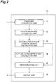
- FIG. 2 is a functional block diagram of the abnormality determination device according to the present embodiment.
- the abnormality determination device 10 shown in FIG. 2 is a device that determines an abnormality of the inducer 2.
- the abnormality determination device 10 determines an abnormality of the inducer 2 based on the accumulated fatigue-damage degree of the inducer 2 of the rocket 1.
- FIG. 3 is a hardware configuration diagram of the abnormality determination device 10.
- the abnormality determination device 10 can be constituted physically as a computer including hardware of one or more processors 101, a storage device 102 which is a main storage device such as a random access memory (RAM) or a read only memory (ROM), an auxiliary storage device 103 such as a hard disk device, an input device 104 such as a keyboard, an output device 105 such as a display, and a communication device 106 which is a data transmission/reception device, and the like.
- RAM random access memory
- ROM read only memory
- auxiliary storage device 103 such as a hard disk device
- an input device 104 such as a keyboard
- an output device 105 such as a display
- a communication device 106 which is a data transmission/reception device, and the like.
- FIG. 2 is implemented by loading one or more predetermined computer programs in hardware such as one or more processors 101 and the storage device 102 to operate the hardware under the control of one or more processors 101, and by reading and writing data in the storage device 102 and the auxiliary storage device 103.
- the abnormality determination device 10 includes a pressure acquisition unit 11, a stress-response acquisition unit 12, an accumulated-fatigue-damage-degree calculation unit 13, a lifetime-consumption-rate calculation unit 14, a determination unit 15, and an output unit 16.
- the pressure acquisition unit 11 functions as pressure acquisition means for acquiring the pressure at the input side of the inducer 2.
- the pressure acquisition unit 11 acquires the pressure measured by the pressure sensor 4.
- the pressure acquisition unit 11 samples the pressure measured by the pressure sensor 4 at sampling intervals ⁇ T of, for example, about 10 kHz to obtain a pressure response.
- the pressure response is a pressure sequence indicating a temporal change in the pressure at the input side of the inducer 2 and arranging the pressure at the input side of the inducer 2 at predetermined time intervals in time series.
- the pressure acquisition unit 11 outputs the pressure response to the stress-response acquisition unit 12.
- the stress-response acquisition unit 12 functions as stress-response acquisition means for acquiring a stress response based on the pressure response acquired by the pressure acquisition unit 11.
- the stress response is a stress sequence indicating a temporal change in the stress applied to the inducer 2, and arranging the stress applied to the inducer 2 at predetermined time intervals in time series.
- the stress-response acquisition unit 12 converts the pressure response into the stress response using a preset transfer function.
- the transfer function is a function that defines the relation between the pressure measured by the pressure sensor 4 and the stress applied to the inducer 2.
- a distortion sensor is provided in the inducer 2, and a function defining the relation between the pressure measured by the pressure sensor 4 and the distortion of the inducer 2 measured by the distortion sensor is obtained in advance as the transfer function.
- the stress-response acquisition unit 12 outputs the acquired stress response to the accumulated-fatigue-damage-degree calculation unit 13.
- the accumulated-fatigue-damage-degree calculation unit 13 functions as accumulated-fatigue-damage-degree calculation means for calculating the accumulated fatigue-damage degree of the inducer 2 based on the stress response acquired by the stress-response acquisition unit 12.
- the accumulated-fatigue-damage-degree calculation unit 13 decomposes the stress response into sets of stress amplitude and average stress using, for example, a rainflow-counting algorithm.
- FIGS. 4 and 5 are diagrams for explaining the decomposition of the stress response using the rainflow-counting algorithm.
- the horizontal axis indicates time (axis) and the vertical axis indicates stress ⁇ .
- the accumulated-fatigue-damage-degree calculation unit 13 extracts an evaluation target from the stress response in a sampling section T.
- the sampling section T is predetermined based on the minimum cycle in which stress response is evaluated.
- a sampling interval ⁇ T is predetermined based on the maximum cycle in which stress response is evaluated.
- the sampling section T is, for example, about several seconds.
- the accumulated-fatigue-damage-degree calculation unit 13 extracts the maximum value and the minimum value of the evaluation target, and divides the evaluation target into the first half portion R1 and the second half portion R2 of the horizontal axis by setting the maximum value as the boundary.
- the accumulated-fatigue-damage-degree calculation unit 13 connects the first half portion R1 behind the second half portion R2 to generate a container in a shape having the maximum values at both ends.
- the accumulated-fatigue-damage-degree calculation unit 13 virtually fills the container with water.
- the accumulated-fatigue-damage-degree calculation unit 13 calculates the difference between the maximum water level point Wmax1 and the minimum water level point Wmin1 as the stress amplitude ⁇ a1 , and calculates an intermediate value between the maximum water level point Wmax1 and the minimum water level point Wmin1 as the average stress ⁇ m1 .
- the accumulated-fatigue-damage-degree calculation unit 13 assigns a new number i to a set in, for example, ascending order each time a different set is obtained by the decomposition.
- the accumulated-fatigue-damage-degree calculation unit 13 drains the water from the minimum water level point Wmin1 and determines the new minimum water level point Wmin2.
- the accumulated-fatigue-damage-degree calculation unit 13 calculates the stress amplitude ⁇ a2 and the average stress ⁇ m2 using the maximum water level point Wmax2 of the storage of the water corresponding to the minimum water level point Wmin2 and the minimum water level point Wmin2. Similarly, as shown in FIG.
- the accumulated-fatigue-damage-degree calculation unit 13 drains the water from the minimum water level point Wmin2, determines the new minimum water level point Wmin3, and calculates the stress amplitude ⁇ a3 and the average stress ⁇ m3 using the maximum water level point Wmax3 and the minimum water level point Wmin3.
- the accumulated-fatigue-damage-degree calculation unit 13 drains the water from the minimum water level point Wmin3, determines the new minimum water level point Wmin4, and calculates the stress amplitude ⁇ a4 and the average stress ⁇ m4 using the maximum water level point Wmax4 and the minimum water level point Wmin4.
- the accumulated-fatigue-damage-degree calculation unit 13 decomposes the stress response of the evaluation target into a plurality of sets ( ⁇ ai , ⁇ mi ).
- the accumulated-fatigue-damage-degree calculation unit 13 counts the number of times n i each set is obtained. In this example, each of the number of times n 1 to n 4 is 1 in the decomposition shown in FIGS. 4 and 5 . Then, the accumulated-fatigue-damage-degree calculation unit 13 performs the similar processing for the next sampling section T. When a different set is obtained by further decomposition, the accumulated-fatigue-damage-degree calculation unit 13 assigns the number i to the set as a sequential number of the sets obtained by the previous decomposition.
- the accumulated-fatigue-damage-degree calculation unit 13 calculates, for each of k (an integer of 1 or more) sets ( ⁇ ai , ⁇ mi ), an equivalent stress amplitude S si using the modified Goodman diagram expressed by Formula (1).
- the equivalent stress amplitude S si is variable stress modified in consideration of the influence on fatigue strength when there is an average stress.
- a tensile strength S b is the tensile strength of the blade material of the inducer 2, which is a fixed value predetermined by the material of the blade.
- the number i is an integer of 1 or more and k or less.
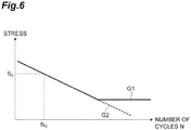
- FIG. 6 is a diagram showing an S-N curve of the blade material of the inducer 2.
- the horizontal axis indicates the number of cycles N
- the vertical axis indicates the stress amplitude.
- the S-N curve indicates the number of cycles N at which the inducer 2 is damaged when only stress of each stress amplitude is applied. This S-N curve is determined based on the fatigue test result of the blade material of the inducer 2.
- the graph G1 in FIG. 6 shows the Minor's rule and the graph G2 shows the modified Minor's rule.
- the accumulated-fatigue-damage-degree calculation unit 13 calculates, with Formula (2), the number of cycles N i at which the inducer 2 is damaged when only the stress of the equivalent stress amplitude S si is applied to the inducer 2.
- the reference number of cycles N 0 is the number of cycles at which the inducer 2 is damaged when only the stress of a reference stress amplitude S 0 is applied to the inducer 2.
- an accumulated fatigue-damage degree ⁇ (t) is expressed by Formula (3).
- the accumulated fatigue-damage degree ⁇ (t) is the accumulated fatigue-damage degree from the start time of the n-th flight to the time when an elapsed time t has elapsed.
- the elapsed time t is the elapsed time from the start time of the n-th flight, and uses the sampling interval ⁇ T as a unit time. That is, each time the elapsed time from the start time of the n-th flight increases by the sampling interval ⁇ T, "1" is added to the elapsed time t.
- a time when the elapsed time t has elapsed from the start time of the n-th flight may be simply referred to as an "elapsed time t".
- the accumulated-fatigue-damage-degree calculation unit 13 calculates the accumulated fatigue-damage degree ⁇ (t) with Formula (3).
- the accumulated-fatigue-damage-degree calculation unit 13 calculates the accumulated fatigue-damage degree ⁇ (t) at each sampling interval ⁇ T and outputs the calculated accumulated fatigue-damage degree ⁇ (t) to the lifetime-consumption-rate calculation unit 14 and the determination unit 15.
- the lifetime-consumption-rate calculation unit 14 functions as lifetime-consumption-rate calculation means for calculating a lifetime consumption rate ⁇ '(t) that is a changing rate of the accumulated fatigue-damage degree ⁇ (t) with respect to time.
- the lifetime-consumption-rate calculation unit 14 calculates the difference ⁇ of the accumulated fatigue-damage degrees ⁇ (t) received from the accumulated-fatigue-damage-degree calculation unit 13 at each sampling interval ⁇ T. That is, the lifetime-consumption-rate calculation unit 14 calculates the difference ⁇ (t) at the time when the elapsed time t has elapsed by subtracting the accumulated fatigue-damage degree ⁇ (t-1) from the accumulated fatigue-damage degree ⁇ (t).
- the lifetime-consumption-rate calculation unit 14 calculates the lifetime consumption rate ⁇ '(t) at the elapsed time t by dividing the difference ⁇ (t) by the sampling interval ⁇ T.
- the determination unit 15 functions as determination means for determining an abnormality of the inducer 2 based on the accumulated fatigue-damage degree ⁇ and the lifetime consumption rate ⁇ '(t) of the inducer 2.
- the outline of the abnormality determination of the inducer 2 by the determination unit 15 is described.
- FIG. 7 is a diagram for explaining the abnormality determination of the inducer 2.
- the horizontal axis indicates time and the vertical axis indicates the accumulated fatigue-damage degree ⁇ .
- the value obtained by setting the lifetime of the inducer 2 to "1" and dividing the lifetime by a lifetime safety factor sf is a lifetime limit (1/sf).
- the lifetime safety factor sf is a value for setting a margin for the lifetime of the inducer 2, and is, for example, about 1 to 5. That is, the lifetime limit (1/sf) is a value that defines the limit of the acceptable damage degree of the inducer 2.
- the inducer 2 operates only for the use time X per flight of the rocket 1.
- the accumulated fatigue-damage degree ⁇ n-1 is accumulated by the flights up to the (n-1)th flight.
- the remaining lifetime is, for example, (1/sf - ⁇ n-1 ).
- the inducer 2 is determined to be normal when the accumulated fatigue-damage degree ⁇ does not exceed the lifetime limit (1/sf), and the inducer 2 is determined to be abnormal when the accumulated fatigue-damage degree ⁇ exceeds the lifetime limit (1/sf). That is, the determination unit 15 predicts, based on the accumulated fatigue-damage degree ⁇ (t) and the lifetime consumption rate ⁇ '(1), whether the accumulated fatigue-damage degree ⁇ exceeds the lifetime limit (1/sf) during the n-th flight. The determination unit 15 determines that the inducer 2 is abnormal when predicting that the accumulated fatigue-damage degree ⁇ exceeds the lifetime limit (1/sf) during the n-th flight.
- the determination unit 15 determines that the inducer 2 is normal when predicting that the accumulated fatigue-damage degree ⁇ does not exceed the lifetime limit (1/sf) during the n-th flight. Specifically, on the assumption that the lifetime of the inducer 2 is continuously consumed at the lifetime consumption rate ⁇ '(t) at the elapsed time t, the determination unit 15 performs the abnormality determination of the inducer 2 based on whether the accumulated fatigue-damage degree ⁇ exceeds the lifetime limit (1/sf) during the n-th flight.
- the determination unit 15 determines the abnormality of the inducer 2 using a determination value D(t) shown in Formula (5).
- D(t) 1 sf ⁇ ⁇ n ⁇ 1 + ⁇ n t ⁇ ′ t + t ⁇ X
- the value obtained by adding the accumulated fatigue-damage degree ⁇ n (t) from the start time of the n-th flight to the time when the elapsed time t has elapsed to the accumulated fatigue-damage degree ⁇ n-1 up to the (n-1)th flight of the rocket 1 is the accumulated fatigue-damage degree ⁇ from the start time of the first flight to the elapsed time t in the n-th flight.
- the determination unit 15 calculates the remaining lifetime based on the lifetime limit (1/sf) and the accumulated fatigue-damage degree ⁇ . For example, the determination unit 15 subtracts the accumulated fatigue-damage degree ⁇ from the lifetime limit (1/sf), and determines the subtraction result as the remaining lifetime at the elapsed time t. That is, as shown by the numerators of the first term on the right side of Formula (5), the determination unit 15 calculates the remaining lifetime at the elapsed time t.
- the determination unit 15 calculates a remaining time tr(t) based on the remaining lifetime and the lifetime consumption rate ⁇ '(t). For example, as shown in the first term on the right side of Formula (5), the determination unit 15 calculates the remaining time tr(t) by dividing the remaining lifetime by the lifetime consumption rate ⁇ '(t). The remaining time tr(t) is the time until the accumulated fatigue-damage degree ⁇ reaches the lifetime limit (1/sf) when the lifetime of the inducer 2 is continuously consumed at the lifetime consumption rate ⁇ '(t).
- the determination unit 15 predicts, based on the remaining time tr(t) and the elapsed time t, whether the accumulated fatigue-damage degree ⁇ exceeds the lifetime limit (1/sf) during the n-th flight. Specifically, the determination unit 15 predicts that the accumulated fatigue-damage degree ⁇ exceeds the lifetime limit (1/sf) during the n-th flight when the sum of the remaining time tr(t) and the elapsed time t is shorter than the use time X, and that the accumulated fatigue-damage degree ⁇ does not exceed the lifetime limit (1/sf) during the n-th flight when the sum of the remaining time tr(t) and the elapsed time t is equal to or longer than the use time X.
- the determination unit 15 predicts that the accumulated fatigue-damage degree ⁇ exceeds the lifetime limit (1/sf) during the n-th flight, and determines that the inducer 2 is abnormal.
- the determination unit 15 predicts that the accumulated fatigue-damage degree ⁇ does not exceed the lifetime limit (1/sf) during the n-th flight, and determines that the inducer 2 is normal.
- the inducer 2 may be determined to be abnormal when the lifetime consumption rate ⁇ '(t) is greater than a reference value ⁇ ' cri which is the inclination of the graph G cri , and to be normal when the lifetime consumption rate ⁇ '(t) is equal to or less than the reference value ⁇ ' cri . That is, as shown in Formula (7), the determination unit 15 may determine that the inducer 2 is abnormal when the lifetime consumption rate ⁇ '(t) is greater than the predetermined reference value ⁇ ' cri , and that the inducer 2 is normal when the lifetime consumption rate ⁇ '(t) is equal to or less than the predetermined reference value ⁇ ' cri .
- the reference value ⁇ ' cri is preset by experiments or the like. [Formula 7] ⁇ ′ t > ⁇ cri ′
- the determination unit 15 outputs a determination result indicating whether the inducer 2 is abnormal or normal to the output unit 16.
- the output unit 16 functions as output means for outputting the determination result determined by the determination unit 15.
- the output unit 16 outputs the determination result to the output device 105 (see FIG. 3 ) such as a display.
- the output unit 16 may transmit a stop instruction to the control unit of the rocket 1 so as to safely stop the operation of the rocket 1.
- FIG. 8 is a flowchart showing an example of the abnormality determination method performed by the abnormality determination device 10. A series of processing shown in FIG. 8 is started at the timing when the n-th flight of the rocket 1 is started.
- the pressure acquisition unit 11 acquires the pressure measured by the pressure sensor 4 as the pressure at the input side of the inducer 2 (step ST11). Specifically, the pressure acquisition unit 11 acquires a pressure response of the pressure at the input side of the inducer 2 by sampling the pressure measured by the pressure sensor 4. Then, the pressure acquisition unit 11 outputs the pressure response to the stress-response acquisition unit 12.
- the stress-response acquisition unit 12 acquires a stress response based on the pressure response (step ST12). Specifically, the stress-response acquisition unit 12 converts the pressure response into the stress response using a preset transfer function. Then, The stress-response acquisition unit 12 outputs the stress response to the accumulated-fatigue-damage-degree calculation unit 13.
- the accumulated-fatigue-damage-degree calculation unit 13 calculates an accumulated fatigue-damage degree ⁇ (t) of the inducer 2 based on the stress response acquired by the stress-response acquisition unit 12 (step ST13). Specifically, the accumulated-fatigue-damage-degree calculation unit 13 decomposes the stress response into a plurality of sets ( ⁇ ai , ⁇ mi ) using, for example, a rainflow-counting algorithm. Then, the accumulated-fatigue-damage-degree calculation unit 13 calculates, for each set ( ⁇ ai , ⁇ mi ), an equivalent stress amplitude S si with Formula (1).
- the accumulated-fatigue-damage-degree calculation unit 13 calculates, with Formula (2), the number of cycles N i at which the inducer 2 is damaged when only the stress of the equivalent stress amplitude S si is applied to the inducer 2. Then, the accumulated-fatigue-damage-degree calculation unit 13 calculates the accumulated fatigue-damage degree ⁇ (t) with Formula (3) and outputs it to the lifetime-consumption-rate calculation unit 14 and the determination unit 15.
- the lifetime-consumption-rate calculation unit 14 calculates a lifetime consumption rate ⁇ '(t) (step ST14). Specifically, the lifetime-consumption-rate calculation unit 14 calculates the difference ⁇ (t) between the accumulated fatigue-damage degree ⁇ (t) and the accumulated fatigue-damage degree ⁇ (t-1). Then, the lifetime-consumption-rate calculation unit 14 calculates the lifetime consumption rate ⁇ '(t) with Formula (4), and outputs the lifetime consumption rate ⁇ '(t) to the determination unit 15.
- the determination unit 15 calculates a determination value D(t) with Formula (5) (Step ST15). Then, the determination unit 15 performs abnormality determination of the inducer 2 (step ST16). Specifically, as shown in Formula (6), when the determination value D(t) is a negative value, the determination unit 15 predicts that the accumulated fatigue-damage degree ⁇ exceeds the lifetime limit (1/sf) during the n-th flight, and determines that the inducer 2 is abnormal. When the determination value D(t) is equal to or greater than 0, the determination unit 15 predicts that the accumulated fatigue-damage degree ⁇ does not exceed the lifetime limit (1/sf) during the n-th flight, and determines that the inducer 2 is normal.
- the determination unit 15 may determine that the inducer 2 is abnormal when the lifetime consumption rate ⁇ '(t) is greater than the reference value ⁇ ' cri , and that the inducer 2 is normal when the lifetime consumption rate ⁇ '(t) is equal to or less than the reference value ⁇ ' cri . Then, the determination unit 15 outputs a determination result indicating whether the inducer 2 is abnormal or normal to the output unit 16.
- the output unit 16 determines whether the inducer 2 is abnormal or normal based on the determination result (step ST17).
- the determination result indicates that the inducer 2 is normal (step ST17; No)
- the output unit 16 outputs the determination result to the output device 105 (see FIG. 3 ) such as a display, and the processing in steps ST11 to ST17 is repeated at the next elapsed time t+1.
- the processing in steps ST11 to ST17 is repeated at each sampling interval ⁇ T.
- step ST17 when the determination result indicates that the inducer 2 is abnormal (step ST17: Yes), the output unit 16 outputs the determination result to the output device 105 such as a display, and transmits a stop instruction to the control unit of the rocket 1 so as to safely stop the operation of the rocket 1 (step ST18).
- the output unit 16 outputs the determination result to the output device 105 such as a display, and transmits a stop instruction to the control unit of the rocket 1 so as to safely stop the operation of the rocket 1 (step ST18).
- the output unit 16 outputs the determination result to the output device 105 such as a display, and transmits a stop instruction to the control unit of the rocket 1 so as to safely stop the operation of the rocket 1 (step ST18).
- the accumulated fatigue-damage degree ⁇ of the inducer 2 is calculated based on the stress response applied to the inducer 2, and the lifetime consumption rate ⁇ '(t) that is a changing rate of the accumulated fatigue-damage degree ⁇ with respect to time is calculated. Then, based on the accumulated fatigue-damage degree ⁇ and the lifetime consumption rate ⁇ '(t), an abnormality of the inducer 2 is determined.
- the use time X for which the inducer 2 is used in one flight is predetermined, and it is possible to safely perform the operation of the rocket 1 unless the accumulated fatigue-damage degree ⁇ of the inducer 2 reaches the end of the lifetime of the inducer 2 during the use time X.
- a threshold for the accumulated fatigue-damage degree ⁇ it can be considered that the inducer 2 is determined to be abnormal when the accumulated fatigue-damage degree ⁇ exceeds the threshold.
- the accumulated fatigue-damage degree ⁇ is not always accumulated at a certain rate.
- abnormality of the inducer 2 cannot be determined at an appropriate timing.
- the threshold is set to be large in consideration of safety, although the rocket 1 is able to be safely operated, the inducer 2 can be determined to be abnormal.
- the abnormality determination device 10 by taking not only the accumulated fatigue-damage degree ⁇ but also the lifetime consumption rate ⁇ '(t) into consideration, it is possible to determine an abnormality of the inducer 2 according to the accumulation speed (lifetime consumption rate ⁇ '(t)) of the accumulated fatigue-damage degree ⁇ . As a result, it is possible to improve the accuracy of abnormality determination of the inducer 2.
- the inducer 2 based on the accumulated fatigue-damage degree ⁇ and the lifetime consumption rate ⁇ '(t), it is predicted whether the accumulated fatigue-damage degree ⁇ of the inducer 2 exceeds the lifetime limit (1/sf) of the inducer 2 during the n-th flight of the rocket 1. If the accumulated fatigue-damage degree ⁇ exceeds the lifetime limit (1/sf) during the n-th flight of the rocket 1, the inducer 2 can be damaged. Thus, when it is predicted that the accumulated fatigue-damage degree ⁇ exceeds the lifetime limit (1/sf) during the n-th flight of the rocket 1, the inducer 2 is determined to be abnormal. As a result, it is possible to determine an abnormality of the inducer before the inducer 2 is damaged.
- the remaining lifetime is calculated by subtracting the accumulated fatigue-damage degree ⁇ from the lifetime limit (1/sf) at the time when the elapsed time t has elapsed from the start time of the n-th flight of the rocket 1. Then, by dividing the remaining lifetime by the lifetime consumption rate ⁇ '(t) at the elapsed time t, the remaining time tr(t) until the accumulated fatigue-damage degree ⁇ reaches the lifetime limit (1/sf) is calculated. Then, based on the remaining time tr(t) and the elapsed time t, it is predicted whether the accumulated fatigue-damage degree ⁇ exceeds the lifetime limit (1/sf) during the n-th flight of the rocket 1.
- Whether the accumulated fatigue-damage degree ⁇ exceeds the lifetime limit (1/sf) during the n-th flight of the rocket 1 is determined by the magnitude relation between the sum of the remaining time tr(t) and the elapsed time t, and the use time X.
- the sum of the remaining time tr(t) and the elapsed time t is shorter than the use time X, it is predicted that the accumulated fatigue-damage degree ⁇ exceeds the lifetime limit (1/sf) during the n-th flight of the rocket 1. That is, based on the assumption that the remaining lifetime is consumed at the lifetime consumption rate ⁇ '(t), it is predicted whether the accumulated fatigue-damage degree ⁇ exceeds the lifetime limit (1/sf) during the n-th flight of rocket 1.
- the inducer 2 is determined to be normal. However, since it is predicted that the accumulated fatigue-damage degree ⁇ exceeds the lifetime limit (1/sf) at the elapsed time t 3 , the inducer 2 is determined to be abnormal. In this manner, by monitoring the lifetime consumption rate ⁇ '(t) during the flight of the rocket 1 in real time, it is possible to determine whether the lifetime of the inducer 2 is ended during the flight of the rocket 1.
- the excitation force generated in the inducer 2 increases due to some abnormality, and the distortion amplitude increases excessively for the structure.
- the lifetime limit (1/sf) is set to have a margin for the lifetime of the inducer 2 in order to prevent the inducer 2 from being damaged by high-cycle fatigue, it is possible to stop the engine of the rocket 1 with the margin for the lifetime of the inducer 2.
- the inducer 2 may be provided with a distortion sensor.
- the stress-response acquisition unit 12 may directly acquire a stress response based on the distortion of the inducer 2 measured by the distortion sensor.
- the pressure acquisition unit 11 can be omitted.
- the stress-response acquisition unit 12 may acquire a stress response based on a pressure response.
- the accumulated-fatigue-damage-degree calculation unit 13 may calculate the accumulated fatigue-damage degree ⁇ by adding the accumulated fatigue-damage degree ⁇ n-1 up to the (n-1)th flight to the accumulated fatigue-damage degree ⁇ (t). In this case, the accumulated-fatigue-damage-degree calculation unit 13 may output the accumulated . fatigue-damage degree ⁇ to the lifetime-consumption-rate calculation unit 14 and the determination unit 15.
- the output unit 16 may not transmit a stop instruction to the control unit of the rocket 1.
- An administrator may confirm the determination result output to the output device 105 such as a display and manually transmit the stop instruction to the control unit of the rocket 1.
- the abnormality determination device 10 may determine not only an abnormality of the inducer 2 of the turbo pump of the rocket 1 but also an abnormality of an inducer for a general industrial pump.
- the inducer is used for a predetermined use time X per operation of the pump.
- the abnormality determination device 10 may determine an abnormality of components used for a predetermined use time X per operation.
- the pressure acquisition unit 11, the stress-response acquisition unit 12, the accumulated-fatigue-damage-degree calculation unit 13, the lifetime-consumption-rate calculation unit 14, the determination unit 15, and the output unit 16 operate similarly to those in the above embodiment.
- the abnormality determination device and the abnormality determination method of the present disclosure it is possible to improve the accuracy of abnormality determination.
Landscapes
- Engineering & Computer Science (AREA)
- Mechanical Engineering (AREA)
- General Engineering & Computer Science (AREA)
- Physics & Mathematics (AREA)
- General Physics & Mathematics (AREA)
- Chemical & Material Sciences (AREA)
- Combustion & Propulsion (AREA)
- Aviation & Aerospace Engineering (AREA)
- Automation & Control Theory (AREA)
- Structures Of Non-Positive Displacement Pumps (AREA)
- Testing Of Devices, Machine Parts, Or Other Structures Thereof (AREA)
- Control Of Non-Positive-Displacement Pumps (AREA)
Abstract
Description
- The present disclosure relates to an abnormality determination device and an abnormality determination method.
- Conventionally, a diagnostic system for predicting the lifetimes of components and the like is known. For example,
Patent Literature 1 discloses a system for diagnosing a fatigue-damage degree of a vehicle to warn that the lifetime of a front side member is coming to the end by calculating the fatigue-damage degree of the front side member based on an input detected by a sensor. - Patent Literature 1: Japanese Unexamined Patent Publication No.
2013-79920 - In a flying object such as an unmanned spacecraft, if an inducer is damaged during a flight, a safety measure may be taken by destroying the airframe. However, in the case of a manned flying object, destroying the airframe is not acceptable. For this reason, it is required to detect an abnormality before the inducer is damaged and to safely stop the operation.
- A use time for which an inducer is used in one flight is predetermined, and it is possible to safely operate unless the accumulated fatigue-damage degree of the inducer reaches the end of the lifetime of the inducer during the use time. However, the damage is accumulated in an inducer of a flying object due to various factors. For example, in the inducer, minute cavitation occurs randomly in a normal operation state, and this excitation force generates stress, which can lead to destruction of the inducer. In this manner, damage is not always accumulated at a certain rate.
- In the system for diagnosing a fatigue-damage degree disclosed in
Patent Literature 1, since the warning threshold is preset, warning cannot be made at an appropriate timing if the accumulation speed of the fatigue-damage degree changes. For example, when the operation can be safely performed, the inducer can be determined to be abnormal according to the setting of the warning threshold. In this manner, it is desired to improve the accuracy of abnormality determination of a component (inducer) used only for a predetermined use time per operation. - An abnormality determination device according to an aspect of the present disclosure is a device that determines an abnormality of an inducer used for a pump. The abnormality determination device includes a stress-response acquisition unit that acquires a stress response indicating a temporal change in stress applied to the inducer, an accumulated-fatigue-damage-degree calculation unit that calculates an accumulated fatigue-damage degree of the inducer based on the stress response, a lifetime-consumption-rate calculation unit that calculates a lifetime consumption rate that is a changing rate of the accumulated fatigue-damage degree with respect to time, and a determination unit that determines an abnormality of the inducer based on the accumulated fatigue-damage degree and the lifetime consumption rate. The inducer is used only for a predetermined use time per operation of the pump.
- According to the present disclosure, it is possible to improve the accuracy of abnormality determination.
-
-
FIG. 1 is a diagram schematically showing an example of a determination target of an abnormality determination device according to the present embodiment. -
FIG. 2 is a functional block diagram of the abnormality determination device according to the present embodiment. -
FIG. 3 is a hardware configuration diagram of the abnormality determination device inFIG. 2 . -
FIGS. 4(a) to 4(c) are diagrams for explaining decomposition of a stress response using a rainflow-counting algorithm. -
FIGS. 5(a) to 5(c) are diagrams for explaining decomposition of the stress response using the rainflow-counting algorithm. -
FIG. 6 is a diagram showing an S-N curve of a blade material of an inducer. -
FIG. 7 is a diagram for explaining abnormality determination of an inducer. -
FIG. 8 is a flowchart showing an example of an abnormality determination method performed by the abnormality determination device inFIG. 2 . - An abnormality determination device according to an aspect of the present disclosure is a device that determines an abnormality of an inducer used for a pump. The abnormality determination device includes a stress-response acquisition unit that acquires a stress response indicating a temporal change in stress applied to the inducer, an accumulated-fatigue-damage-degree calculation unit that calculates an accumulated fatigue-damage degree of the inducer based on the stress response, a lifetime-consumption-rate calculation unit that calculates a lifetime consumption rate that is a changing rate of the accumulated fatigue-damage degree with respect to time, and a determination unit that determines an abnormality of the inducer based on the accumulated fatigue-damage degree and the lifetime consumption rate. The inducer is used only for a predetermined use time per operation of the pump.
- An abnormality determination method according to another aspect of the present disclosure is an abnormality determination method performed by an abnormality determination device that determines an abnormality of an inducer used for a pump. The abnormality determination method includes the steps of acquiring a stress response indicating a temporal change in stress applied to the inducer, calculating an accumulated fatigue-damage degree of the inducer based on the stress response, calculating a lifetime consumption rate that is a changing rate of the accumulated fatigue-damage degree with respect to time, and determining an abnormality of the inducer based on the accumulated fatigue-damage degree and the lifetime consumption rate. The inducer is used only for a predetermined use time per operation of the pump.
- In the abnormality determination device and the abnormality determination method, the accumulated fatigue-damage degree of the inducer is calculated based on the stress response applied to the inducer, and the lifetime consumption rate that is a changing rate of the accumulated fatigue-damage degree with respect to time is calculated. Then, based on the accumulated fatigue-damage degree and the lifetime consumption rate, an abnormality of the inducer is determined. In this manner, by taking not only the accumulated fatigue-damage degree but also the lifetime consumption rate into consideration, it is possible to determine an abnormality of the inducer according to the accumulation speed (lifetime consumption rate) of the accumulated fatigue-damage degree. As a result, it is possible to improve the accuracy of abnormality determination of the inducer.
- The abnormality determination device may further include a pressure acquisition unit that acquires pressure at an input side of the inducer. The stress-response acquisition unit may acquire the stress response based on a pressure response indicating a temporal change in the pressure. In this case, when the stress applied to the inducer cannot be directly measured, it is possible to indirectly acquire the stress response of the stress applied to the inducer by measuring the pressure at the input side of the inducer.
- The determination unit may predict, based on the accumulated fatigue-damage degree and the lifetime consumption rate, whether the accumulated fatigue-damage degree exceeds a lifetime limit defining a limit of a damage degree of the inducer during the operation, and may determine that the inducer is abnormal when predicting that the accumulated fatigue-damage degree exceeds the lifetime limit during the operation. If the accumulated fatigue-damage degree exceeds the lifetime limit of the inducer during the operation, the inducer can be damaged. Thus, when it is predicted that the accumulated fatigue-damage degree exceeds the lifetime limit of the inducer during the operation, the inducer is determined to be abnormal. As a result, it is possible to determine an abnormality of the inducer before the inducer is damaged.
- The determination unit may calculate a remaining lifetime at a time when a predetermined elapsed time has elapsed from a start time of the operation by subtracting the accumulated fatigue-damage degree from the lifetime limit, may calculate a remaining time until the accumulated fatigue-damage degree reaches the lifetime limit by dividing the remaining lifetime by the lifetime consumption rate, and may predict, based on the remaining time and the elapsed time, whether the accumulated fatigue-damage degree exceeds the lifetime limit during the operation. In this case, it is predicted whether the accumulated fatigue-damage degree exceeds the lifetime limit during the operation based on the assumption that the remaining lifetime is consumed at the lifetime consumption rate at the time when the elapsed time has elapsed. Thus, when the lifetime consumption rate is changed due to some factor during the operation, it is possible to determine an abnormality of the inducer according to the lifetime consumption rate. As a result, it is possible to improve the accuracy of abnormality determination of the inducer.
- The determination unit may predict that the accumulated fatigue-damage degree exceeds the lifetime limit during the operation when the sum of the remaining time and the elapsed time is shorter than the use time. Whether the accumulated fatigue-damage degree exceeds the lifetime limit during the operation is determined by the magnitude relation between the sum of the remaining time and the elapsed time, and the use time. Thus, it is possible to improve the accuracy of the prediction as to whether the accumulated fatigue-damage degree exceeds the lifetime limit during the operation, and to improve the accuracy of the abnormality determination of the inducer.
- The determination unit may determine that the inducer is abnormal when the lifetime consumption rate is greater than a predetermined reference value. When the lifetime consumption rate is greater than the assumed reference value, some kind of abnormality could have occurred in the inducer. Thus, by determining that the inducer is abnormal when the lifetime consumption rate is greater than the reference value, it is possible to determine an abnormality of the inducer before the inducer is damaged. As a result, it is possible to improve the accuracy of abnormality determination of the inducer.
- Hereinafter, an embodiment of the present disclosure is described with reference to the drawings. In the description of the drawings, identical elements are denoted by the same reference signs, and overlapped descriptions are omitted.
-
FIG. 1 is a diagram schematically showing an example of a determination target of an abnormality determination device according to the present embodiment. As shown inFIG. 1 , aninducer 2 provided in a turbo pump of arocket 1 is a determination target. Therocket 1 is a device that obtains propulsive power from reaction by injection, and is a reusable rocket that can be used repeatedly. Therocket 1 is, for example, a liquid rocket. In the rocket engine of therocket 1, liquid fuel F such as liquid hydrogen and liquid oxygen is used as fuel. Therocket 1 is provided with a turbo pump for supplying the high-pressure liquid fuel F. Theinducer 2 is a rotating body provided on the input side of the turbo pump in order to improve the suction performance of the turbo pump. Theinducer 2 is provided in apipe 3 extending in a direction B and rotates about a rotation axis AX extending in the extending direction of thepipe 3. Theinducer 2 sucks the liquid fuel F flowing through thepipe 3 and pressurizes the liquid fuel F. - Since the
inducer 2 sucks the low-pressure liquid fuel F, when the pressure of the liquid fuel F becomes lower than the saturated vapor pressure of the liquid fuel F, the liquid fuel F boils and many small bubbles are generated. Then, when the pressure around the bubbles becomes higher than the saturated vapor pressure of the liquid fuel F, the bubbles disappear. At this moment, since the liquid fuel F around the bubble collides in the vicinity of the center of the bubbles, a pressure wave is generated, and which generates vibration. In this manner, it is known that cavitation occurs in the liquid fuel F, and stress is applied to theinducer 2 by the cavitation. Stress due to various factors besides cavitation is applied to theinducer 2. As the stress is accumulated in theinducer 2, this can damage theinducer 2. Note that, theinducer 2 is used for a predetermined use time X per flight. Especially an inducer blade in theinducer 2 may be a determination target, but in the following description, it is described that theinducer 2 is the determination target. - A
pressure sensor 4 is provided on the inner surface of thepipe 3. Thepressure sensor 4 is disposed, for example, at the substantially same position as the input side front end of theinducer 2 or at an upstream position of the liquid fuel F separated by a predetermined distance from the input side front end of theinducer 2 in the direction B along the rotation axis AX of theinducer 2. Thepressure sensor 4 measures the pressure around the inducer 2 (pressure at the input side), and transmits the measured pressure to anabnormality determination device 10. -
FIG. 2 is a functional block diagram of the abnormality determination device according to the present embodiment. Theabnormality determination device 10 shown inFIG. 2 is a device that determines an abnormality of theinducer 2. Theabnormality determination device 10 determines an abnormality of theinducer 2 based on the accumulated fatigue-damage degree of theinducer 2 of therocket 1. -
FIG. 3 is a hardware configuration diagram of theabnormality determination device 10. As shown inFIG. 3 , theabnormality determination device 10 can be constituted physically as a computer including hardware of one ormore processors 101, astorage device 102 which is a main storage device such as a random access memory (RAM) or a read only memory (ROM), anauxiliary storage device 103 such as a hard disk device, aninput device 104 such as a keyboard, anoutput device 105 such as a display, and acommunication device 106 which is a data transmission/reception device, and the like. Each function of theabnormality determination device 10 shown inFIG. 2 is implemented by loading one or more predetermined computer programs in hardware such as one ormore processors 101 and thestorage device 102 to operate the hardware under the control of one ormore processors 101, and by reading and writing data in thestorage device 102 and theauxiliary storage device 103. - Returning to
FIG. 2 , the details of theabnormality determination device 10 is described. Theabnormality determination device 10 includes apressure acquisition unit 11, a stress-response acquisition unit 12, an accumulated-fatigue-damage-degree calculation unit 13, a lifetime-consumption-rate calculation unit 14, adetermination unit 15, and anoutput unit 16. - The
pressure acquisition unit 11 functions as pressure acquisition means for acquiring the pressure at the input side of theinducer 2. Thepressure acquisition unit 11 acquires the pressure measured by thepressure sensor 4. Thepressure acquisition unit 11 samples the pressure measured by thepressure sensor 4 at sampling intervals ΔT of, for example, about 10 kHz to obtain a pressure response. The pressure response is a pressure sequence indicating a temporal change in the pressure at the input side of theinducer 2 and arranging the pressure at the input side of theinducer 2 at predetermined time intervals in time series. Thepressure acquisition unit 11 outputs the pressure response to the stress-response acquisition unit 12. - The stress-
response acquisition unit 12 functions as stress-response acquisition means for acquiring a stress response based on the pressure response acquired by thepressure acquisition unit 11. The stress response is a stress sequence indicating a temporal change in the stress applied to theinducer 2, and arranging the stress applied to theinducer 2 at predetermined time intervals in time series. The stress-response acquisition unit 12 converts the pressure response into the stress response using a preset transfer function. The transfer function is a function that defines the relation between the pressure measured by thepressure sensor 4 and the stress applied to theinducer 2. For example, a distortion sensor is provided in theinducer 2, and a function defining the relation between the pressure measured by thepressure sensor 4 and the distortion of theinducer 2 measured by the distortion sensor is obtained in advance as the transfer function. The stress-response acquisition unit 12 outputs the acquired stress response to the accumulated-fatigue-damage-degree calculation unit 13. - The accumulated-fatigue-damage-
degree calculation unit 13 functions as accumulated-fatigue-damage-degree calculation means for calculating the accumulated fatigue-damage degree of theinducer 2 based on the stress response acquired by the stress-response acquisition unit 12. The accumulated-fatigue-damage-degree calculation unit 13 decomposes the stress response into sets of stress amplitude and average stress using, for example, a rainflow-counting algorithm. -
FIGS. 4 and5 are diagrams for explaining the decomposition of the stress response using the rainflow-counting algorithm. InFIGS. 4(a) to 4(c) and5(a) to 5(c) , the horizontal axis indicates time (axis) and the vertical axis indicates stress σ. As shown inFIG. 4(a) , the accumulated-fatigue-damage-degree calculation unit 13 extracts an evaluation target from the stress response in a sampling section T. The sampling section T is predetermined based on the minimum cycle in which stress response is evaluated. In addition, a sampling interval ΔT is predetermined based on the maximum cycle in which stress response is evaluated. The sampling section T is, for example, about several seconds. The accumulated-fatigue-damage-degree calculation unit 13 extracts the maximum value and the minimum value of the evaluation target, and divides the evaluation target into the first half portion R1 and the second half portion R2 of the horizontal axis by setting the maximum value as the boundary. - Then, as shown in
FIG. 4(b) , the accumulated-fatigue-damage-degree calculation unit 13 connects the first half portion R1 behind the second half portion R2 to generate a container in a shape having the maximum values at both ends. As shown inFIG. 4(c) , the accumulated-fatigue-damage-degree calculation unit 13 virtually fills the container with water. The accumulated-fatigue-damage-degree calculation unit 13 calculates the difference between the maximum water level point Wmax1 and the minimum water level point Wmin1 as the stress amplitude σa1, and calculates an intermediate value between the maximum water level point Wmax1 and the minimum water level point Wmin1 as the average stress σm1. The accumulated-fatigue-damage-degree calculation unit 13 assigns a new number i to a set in, for example, ascending order each time a different set is obtained by the decomposition. - Next, as shown in
FIG. 5(a) , the accumulated-fatigue-damage-degree calculation unit 13 drains the water from the minimum water level point Wmin1 and determines the new minimum water level point Wmin2. The accumulated-fatigue-damage-degree calculation unit 13 calculates the stress amplitude σa2 and the average stress σm2 using the maximum water level point Wmax2 of the storage of the water corresponding to the minimum water level point Wmin2 and the minimum water level point Wmin2. Similarly, as shown inFIG. 5(b) , the accumulated-fatigue-damage-degree calculation unit 13 drains the water from the minimum water level point Wmin2, determines the new minimum water level point Wmin3, and calculates the stress amplitude σa3 and the average stress σm3 using the maximum water level point Wmax3 and the minimum water level point Wmin3. Similarly, as shown inFIG. 5(c) , the accumulated-fatigue-damage-degree calculation unit 13 drains the water from the minimum water level point Wmin3, determines the new minimum water level point Wmin4, and calculates the stress amplitude σa4 and the average stress σm4 using the maximum water level point Wmax4 and the minimum water level point Wmin4. - In this manner, the accumulated-fatigue-damage-
degree calculation unit 13 decomposes the stress response of the evaluation target into a plurality of sets (σai, σmi). The accumulated-fatigue-damage-degree calculation unit 13 counts the number of times ni each set is obtained. In this example, each of the number of times n1 to n4 is 1 in the decomposition shown inFIGS. 4 and5 . Then, the accumulated-fatigue-damage-degree calculation unit 13 performs the similar processing for the next sampling section T. When a different set is obtained by further decomposition, the accumulated-fatigue-damage-degree calculation unit 13 assigns the number i to the set as a sequential number of the sets obtained by the previous decomposition. - The accumulated-fatigue-damage-
degree calculation unit 13 calculates, for each of k (an integer of 1 or more) sets (σai, σmi), an equivalent stress amplitude Ssi using the modified Goodman diagram expressed by Formula (1). The equivalent stress amplitude Ssi is variable stress modified in consideration of the influence on fatigue strength when there is an average stress. A tensile strength Sb is the tensile strength of the blade material of theinducer 2, which is a fixed value predetermined by the material of the blade. The number i is an integer of 1 or more and k or less.
[Formula 1]
-
FIG. 6 is a diagram showing an S-N curve of the blade material of theinducer 2. InFIG. 6 , the horizontal axis indicates the number of cycles N, and the vertical axis indicates the stress amplitude. The S-N curve indicates the number of cycles N at which theinducer 2 is damaged when only stress of each stress amplitude is applied. This S-N curve is determined based on the fatigue test result of the blade material of theinducer 2. The graph G1 inFIG. 6 shows the Minor's rule and the graph G2 shows the modified Minor's rule. - Based on the S-N curve of the blade material of the
inducer 2, the accumulated-fatigue-damage-degree calculation unit 13 calculates, with Formula (2), the number of cycles Ni at which theinducer 2 is damaged when only the stress of the equivalent stress amplitude Ssi is applied to theinducer 2. The reference number of cycles N0 is the number of cycles at which theinducer 2 is damaged when only the stress of a reference stress amplitude S0 is applied to theinducer 2. The inclination b is the inclination of the S-N curve. In consideration of the stress concentration effect due to alternate stress, the value of the inclination b may be twice the inclination of the S-N curve.
[Formula 2]
- When the modified Minor's rule is used, an accumulated fatigue-damage degree ψ(t) is expressed by Formula (3). The accumulated fatigue-damage degree ψ(t) is the accumulated fatigue-damage degree from the start time of the n-th flight to the time when an elapsed time t has elapsed. Note that, the elapsed time t is the elapsed time from the start time of the n-th flight, and uses the sampling interval ΔT as a unit time. That is, each time the elapsed time from the start time of the n-th flight increases by the sampling interval ΔT, "1" is added to the elapsed time t. In the following description, a time when the elapsed time t has elapsed from the start time of the n-th flight may be simply referred to as an "elapsed time t".
[Formula 3]
- The accumulated-fatigue-damage-
degree calculation unit 13 calculates the accumulated fatigue-damage degree ψ(t) with Formula (3). The accumulated-fatigue-damage-degree calculation unit 13 calculates the accumulated fatigue-damage degree ψ(t) at each sampling interval ΔT and outputs the calculated accumulated fatigue-damage degree ψ(t) to the lifetime-consumption-rate calculation unit 14 and thedetermination unit 15. - The lifetime-consumption-
rate calculation unit 14 functions as lifetime-consumption-rate calculation means for calculating a lifetime consumption rate ψ'(t) that is a changing rate of the accumulated fatigue-damage degree ψ(t) with respect to time. The lifetime-consumption-rate calculation unit 14 calculates the difference Δψ of the accumulated fatigue-damage degrees ψ(t) received from the accumulated-fatigue-damage-degree calculation unit 13 at each sampling interval ΔT. That is, the lifetime-consumption-rate calculation unit 14 calculates the difference Δψ(t) at the time when the elapsed time t has elapsed by subtracting the accumulated fatigue-damage degree ψ(t-1) from the accumulated fatigue-damage degree ψ(t). - As shown in Formula (4), the lifetime-consumption-
rate calculation unit 14 calculates the lifetime consumption rate ψ'(t) at the elapsed time t by dividing the difference Δψ(t) by the sampling interval ΔT. The lifetime-consumption-rate calculation unit 14 outputs the calculated lifetime consumption rate ψ'(t) to thedetermination unit 15.
[Formula 4]
- The
determination unit 15 functions as determination means for determining an abnormality of theinducer 2 based on the accumulated fatigue-damage degree ψ and the lifetime consumption rate ψ'(t) of theinducer 2. Here, with reference toFIG. 7 , the outline of the abnormality determination of theinducer 2 by thedetermination unit 15 is described. -
FIG. 7 is a diagram for explaining the abnormality determination of theinducer 2. InFIG. 7 , the horizontal axis indicates time and the vertical axis indicates the accumulated fatigue-damage degree ψ. The value obtained by setting the lifetime of theinducer 2 to "1" and dividing the lifetime by a lifetime safety factor sf is a lifetime limit (1/sf). The lifetime safety factor sf is a value for setting a margin for the lifetime of theinducer 2, and is, for example, about 1 to 5. That is, the lifetime limit (1/sf) is a value that defines the limit of the acceptable damage degree of theinducer 2. In addition, theinducer 2 operates only for the use time X per flight of therocket 1. At the start time of the n-th flight, the accumulated fatigue-damage degree ψn-1 is accumulated by the flights up to the (n-1)th flight. In this case, the remaining lifetime is, for example, (1/sf - ψn-1). - At the n-th flight, the
inducer 2 is determined to be normal when the accumulated fatigue-damage degree ψ does not exceed the lifetime limit (1/sf), and theinducer 2 is determined to be abnormal when the accumulated fatigue-damage degree ψ exceeds the lifetime limit (1/sf). That is, thedetermination unit 15 predicts, based on the accumulated fatigue-damage degree ψ(t) and the lifetime consumption rate ψ'(1), whether the accumulated fatigue-damage degree ψ exceeds the lifetime limit (1/sf) during the n-th flight. Thedetermination unit 15 determines that theinducer 2 is abnormal when predicting that the accumulated fatigue-damage degree ψ exceeds the lifetime limit (1/sf) during the n-th flight. Thedetermination unit 15 determines that theinducer 2 is normal when predicting that the accumulated fatigue-damage degree ψ does not exceed the lifetime limit (1/sf) during the n-th flight. Specifically, on the assumption that the lifetime of theinducer 2 is continuously consumed at the lifetime consumption rate ψ'(t) at the elapsed time t, thedetermination unit 15 performs the abnormality determination of theinducer 2 based on whether the accumulated fatigue-damage degree ψ exceeds the lifetime limit (1/sf) during the n-th flight. - More specifically, the
determination unit 15 determines the abnormality of theinducer 2 using a determination value D(t) shown in Formula (5).
[Formula 5]
- The value obtained by adding the accumulated fatigue-damage degree ψn(t) from the start time of the n-th flight to the time when the elapsed time t has elapsed to the accumulated fatigue-damage degree ψn-1 up to the (n-1)th flight of the
rocket 1 is the accumulated fatigue-damage degree ψ from the start time of the first flight to the elapsed time t in the n-th flight. Thedetermination unit 15 calculates the remaining lifetime based on the lifetime limit (1/sf) and the accumulated fatigue-damage degree ψ. For example, thedetermination unit 15 subtracts the accumulated fatigue-damage degree ψ from the lifetime limit (1/sf), and determines the subtraction result as the remaining lifetime at the elapsed time t. That is, as shown by the numerators of the first term on the right side of Formula (5), thedetermination unit 15 calculates the remaining lifetime at the elapsed time t. - The
determination unit 15 calculates a remaining time tr(t) based on the remaining lifetime and the lifetime consumption rate ψ'(t). For example, as shown in the first term on the right side of Formula (5), thedetermination unit 15 calculates the remaining time tr(t) by dividing the remaining lifetime by the lifetime consumption rate ψ'(t). The remaining time tr(t) is the time until the accumulated fatigue-damage degree ψ reaches the lifetime limit (1/sf) when the lifetime of theinducer 2 is continuously consumed at the lifetime consumption rate ψ'(t). Thedetermination unit 15 predicts, based on the remaining time tr(t) and the elapsed time t, whether the accumulated fatigue-damage degree ψ exceeds the lifetime limit (1/sf) during the n-th flight. Specifically, thedetermination unit 15 predicts that the accumulated fatigue-damage degree ψ exceeds the lifetime limit (1/sf) during the n-th flight when the sum of the remaining time tr(t) and the elapsed time t is shorter than the use time X, and that the accumulated fatigue-damage degree ψ does not exceed the lifetime limit (1/sf) during the n-th flight when the sum of the remaining time tr(t) and the elapsed time t is equal to or longer than the use time X. - That is, as shown in Formula (6), when the determination value D(t) is a negative value, the
determination unit 15 predicts that the accumulated fatigue-damage degree ψ exceeds the lifetime limit (1/sf) during the n-th flight, and determines that theinducer 2 is abnormal. When the determination value D(t) is equal to or greater than 0, thedetermination unit 15 predicts that the accumulated fatigue-damage degree ψ does not exceed the lifetime limit (1/sf) during the n-th flight, and determines that theinducer 2 is normal.
[Formula 6]
- As shown in
FIG. 7 , theinducer 2 may be determined to be abnormal when the lifetime consumption rate ψ'(t) is greater than a reference value ψ'cri which is the inclination of the graph Gcri, and to be normal when the lifetime consumption rate ψ'(t) is equal to or less than the reference value ψ'cri. That is, as shown in Formula (7), thedetermination unit 15 may determine that theinducer 2 is abnormal when the lifetime consumption rate ψ'(t) is greater than the predetermined reference value ψ'cri, and that theinducer 2 is normal when the lifetime consumption rate ψ'(t) is equal to or less than the predetermined reference value ψ'cri. The reference value ψ'cri is preset by experiments or the like.
[Formula 7]
- The
determination unit 15 outputs a determination result indicating whether theinducer 2 is abnormal or normal to theoutput unit 16. - The
output unit 16 functions as output means for outputting the determination result determined by thedetermination unit 15. Theoutput unit 16 outputs the determination result to the output device 105 (seeFIG. 3 ) such as a display. When the determination result indicates the abnormality, theoutput unit 16 may transmit a stop instruction to the control unit of therocket 1 so as to safely stop the operation of therocket 1. - Next, an example of an abnormality determination method performed by the
abnormality determination device 10 is described.FIG. 8 is a flowchart showing an example of the abnormality determination method performed by theabnormality determination device 10. A series of processing shown inFIG. 8 is started at the timing when the n-th flight of therocket 1 is started. - First, the
pressure acquisition unit 11 acquires the pressure measured by thepressure sensor 4 as the pressure at the input side of the inducer 2 (step ST11). Specifically, thepressure acquisition unit 11 acquires a pressure response of the pressure at the input side of theinducer 2 by sampling the pressure measured by thepressure sensor 4. Then, thepressure acquisition unit 11 outputs the pressure response to the stress-response acquisition unit 12. - Then, the stress-
response acquisition unit 12 acquires a stress response based on the pressure response (step ST12). Specifically, the stress-response acquisition unit 12 converts the pressure response into the stress response using a preset transfer function. Then, The stress-response acquisition unit 12 outputs the stress response to the accumulated-fatigue-damage-degree calculation unit 13. - Subsequently, the accumulated-fatigue-damage-
degree calculation unit 13 calculates an accumulated fatigue-damage degree ψ(t) of theinducer 2 based on the stress response acquired by the stress-response acquisition unit 12 (step ST13). Specifically, the accumulated-fatigue-damage-degree calculation unit 13 decomposes the stress response into a plurality of sets (σai, σmi) using, for example, a rainflow-counting algorithm. Then, the accumulated-fatigue-damage-degree calculation unit 13 calculates, for each set (σai, σmi), an equivalent stress amplitude Ssi with Formula (1). Then, the accumulated-fatigue-damage-degree calculation unit 13 calculates, with Formula (2), the number of cycles Ni at which theinducer 2 is damaged when only the stress of the equivalent stress amplitude Ssi is applied to theinducer 2. Then, the accumulated-fatigue-damage-degree calculation unit 13 calculates the accumulated fatigue-damage degree ψ(t) with Formula (3) and outputs it to the lifetime-consumption-rate calculation unit 14 and thedetermination unit 15. - Subsequently, the lifetime-consumption-
rate calculation unit 14 calculates a lifetime consumption rate ψ'(t) (step ST14). Specifically, the lifetime-consumption-rate calculation unit 14 calculates the difference Δψ(t) between the accumulated fatigue-damage degree ψ(t) and the accumulated fatigue-damage degree ψ(t-1). Then, the lifetime-consumption-rate calculation unit 14 calculates the lifetime consumption rate ψ'(t) with Formula (4), and outputs the lifetime consumption rate ψ'(t) to thedetermination unit 15. - Subsequently, the
determination unit 15 calculates a determination value D(t) with Formula (5) (Step ST15). Then, thedetermination unit 15 performs abnormality determination of the inducer 2 (step ST16). Specifically, as shown in Formula (6), when the determination value D(t) is a negative value, thedetermination unit 15 predicts that the accumulated fatigue-damage degree ψ exceeds the lifetime limit (1/sf) during the n-th flight, and determines that theinducer 2 is abnormal. When the determination value D(t) is equal to or greater than 0, thedetermination unit 15 predicts that the accumulated fatigue-damage degree ψ does not exceed the lifetime limit (1/sf) during the n-th flight, and determines that theinducer 2 is normal. Alternatively, as shown in Formula (7), thedetermination unit 15 may determine that theinducer 2 is abnormal when the lifetime consumption rate ψ'(t) is greater than the reference value ψ'cri, and that theinducer 2 is normal when the lifetime consumption rate ψ'(t) is equal to or less than the reference value ψ'cri. Then, thedetermination unit 15 outputs a determination result indicating whether theinducer 2 is abnormal or normal to theoutput unit 16. - Subsequently, the
output unit 16 determines whether theinducer 2 is abnormal or normal based on the determination result (step ST17). When the determination result indicates that theinducer 2 is normal (step ST17; No), theoutput unit 16 outputs the determination result to the output device 105 (seeFIG. 3 ) such as a display, and the processing in steps ST11 to ST17 is repeated at the next elapsedtime t+ 1. Thereafter, in step ST17, as long as the determination result indicates that theinducer 2 is normal, the processing in steps ST11 to ST17 is repeated at each sampling interval ΔT. - On the other hand, when the determination result indicates that the
inducer 2 is abnormal (step ST17: Yes), theoutput unit 16 outputs the determination result to theoutput device 105 such as a display, and transmits a stop instruction to the control unit of therocket 1 so as to safely stop the operation of the rocket 1 (step ST18). In the above manner, a series of processing of the abnormality determination method performed by theabnormality determination device 10 is terminated. - As described above, in the
abnormality determination device 10 and the abnormality determination method performed by theabnormality determination device 10, the accumulated fatigue-damage degree ψ of theinducer 2 is calculated based on the stress response applied to theinducer 2, and the lifetime consumption rate ψ'(t) that is a changing rate of the accumulated fatigue-damage degree ψ with respect to time is calculated. Then, based on the accumulated fatigue-damage degree ψ and the lifetime consumption rate ψ'(t), an abnormality of theinducer 2 is determined. - The use time X for which the
inducer 2 is used in one flight is predetermined, and it is possible to safely perform the operation of therocket 1 unless the accumulated fatigue-damage degree ψ of theinducer 2 reaches the end of the lifetime of theinducer 2 during the use time X. For example, by presetting a threshold for the accumulated fatigue-damage degree ψ, it can be considered that theinducer 2 is determined to be abnormal when the accumulated fatigue-damage degree ψ exceeds the threshold. However, since damage is accumulated in theinducer 2 ofrocket 1 due to various factors, the accumulated fatigue-damage degree ψ is not always accumulated at a certain rate. Thus, when the accumulation speed (lifetime consumption rate ψ'(t)) of the accumulated fatigue-damage degree ψ changes, abnormality of theinducer 2 cannot be determined at an appropriate timing. For example, when the threshold is set to be large in consideration of safety, although therocket 1 is able to be safely operated, theinducer 2 can be determined to be abnormal. - On the other hand, in the
abnormality determination device 10, by taking not only the accumulated fatigue-damage degree ψ but also the lifetime consumption rate ψ'(t) into consideration, it is possible to determine an abnormality of theinducer 2 according to the accumulation speed (lifetime consumption rate ψ'(t)) of the accumulated fatigue-damage degree ψ. As a result, it is possible to improve the accuracy of abnormality determination of theinducer 2. - Specifically, based on the accumulated fatigue-damage degree ψ and the lifetime consumption rate ψ'(t), it is predicted whether the accumulated fatigue-damage degree ψ of the
inducer 2 exceeds the lifetime limit (1/sf) of theinducer 2 during the n-th flight of therocket 1. If the accumulated fatigue-damage degree ψ exceeds the lifetime limit (1/sf) during the n-th flight of therocket 1, theinducer 2 can be damaged. Thus, when it is predicted that the accumulated fatigue-damage degree ψ exceeds the lifetime limit (1/sf) during the n-th flight of therocket 1, theinducer 2 is determined to be abnormal. As a result, it is possible to determine an abnormality of the inducer before theinducer 2 is damaged. - More specifically, the remaining lifetime is calculated by subtracting the accumulated fatigue-damage degree ψ from the lifetime limit (1/sf) at the time when the elapsed time t has elapsed from the start time of the n-th flight of the
rocket 1. Then, by dividing the remaining lifetime by the lifetime consumption rate ψ'(t) at the elapsed time t, the remaining time tr(t) until the accumulated fatigue-damage degree ψ reaches the lifetime limit (1/sf) is calculated. Then, based on the remaining time tr(t) and the elapsed time t, it is predicted whether the accumulated fatigue-damage degree ψ exceeds the lifetime limit (1/sf) during the n-th flight of therocket 1. Whether the accumulated fatigue-damage degree ψ exceeds the lifetime limit (1/sf) during the n-th flight of therocket 1 is determined by the magnitude relation between the sum of the remaining time tr(t) and the elapsed time t, and the use time X. Thus, when the sum of the remaining time tr(t) and the elapsed time t is shorter than the use time X, it is predicted that the accumulated fatigue-damage degree ψ exceeds the lifetime limit (1/sf) during the n-th flight of therocket 1. That is, based on the assumption that the remaining lifetime is consumed at the lifetime consumption rate ψ'(t), it is predicted whether the accumulated fatigue-damage degree ψ exceeds the lifetime limit (1/sf) during the n-th flight ofrocket 1. - For example, since it is predicted that the accumulated fatigue-damage degree ψ does not exceed the lifetime limit (1/sf) at the elapsed time t1 and elapsed time t2 in
FIG. 7 , theinducer 2 is determined to be normal. However, since it is predicted that the accumulated fatigue-damage degree ψ exceeds the lifetime limit (1/sf) at the elapsed time t3, theinducer 2 is determined to be abnormal. In this manner, by monitoring the lifetime consumption rate ψ'(t) during the flight of therocket 1 in real time, it is possible to determine whether the lifetime of theinducer 2 is ended during the flight of therocket 1. For this reason, when the lifetime consumption rate ψ'(t) changes due to some factor during the flight of therocket 1, it is possible to determine the abnormality of theinducer 2 according to the lifetime consumption rate ψ'(t). As a result, it is possible to improve the accuracy of abnormality determination of theinducer 2. - For example, the excitation force generated in the
inducer 2 increases due to some abnormality, and the distortion amplitude increases excessively for the structure. In such a case, since the lifetime limit (1/sf) is set to have a margin for the lifetime of theinducer 2 in order to prevent theinducer 2 from being damaged by high-cycle fatigue, it is possible to stop the engine of therocket 1 with the margin for the lifetime of theinducer 2. - In addition, when the lifetime consumption rate ψ'(t) is greater than the assumed reference value ψ'cri, some kind of abnormality could have occurred in the
inducer 2. Thus, by determining that theinducer 2 is abnormal when the lifetime consumption rate ψ'(t) is greater than the reference value ψ'cri, it is possible to determine an abnormality of theinducer 2 before theinducer 2 is damaged. As a result, it is possible to improve the accuracy of abnormality determination of theinducer 2. - An embodiment of the present disclosure has been described above, but the present invention is not limited to the above embodiment. For example, the
inducer 2 may be provided with a distortion sensor. In this case, the stress-response acquisition unit 12 may directly acquire a stress response based on the distortion of theinducer 2 measured by the distortion sensor. In this case, thepressure acquisition unit 11 can be omitted. Furthermore, when the distortion of theinducer 2 cannot be measured by the distortion sensor, the stress-response acquisition unit 12 may acquire a stress response based on a pressure response. Thus, when the stress (distortion) applied to theinducer 2 cannot be directly measured, by measuring the pressure at the input side of theinducer 2 by thepressure sensor 4, it is possible to indirectly acquire a stress response of the stress applied to theinducer 2. - Furthermore, the accumulated-fatigue-damage-
degree calculation unit 13 may calculate the accumulated fatigue-damage degree ψ by adding the accumulated fatigue-damage degree ψn-1 up to the (n-1)th flight to the accumulated fatigue-damage degree ψ(t). In this case, the accumulated-fatigue-damage-degree calculation unit 13 may output the accumulated . fatigue-damage degree ψ to the lifetime-consumption-rate calculation unit 14 and thedetermination unit 15. - Furthermore, when the determination result indicates that the
inducer 2 is abnormal, theoutput unit 16 may not transmit a stop instruction to the control unit of therocket 1. An administrator may confirm the determination result output to theoutput device 105 such as a display and manually transmit the stop instruction to the control unit of therocket 1. - Moreover, the
abnormality determination device 10 may determine not only an abnormality of theinducer 2 of the turbo pump of therocket 1 but also an abnormality of an inducer for a general industrial pump. In this case, the inducer is used for a predetermined use time X per operation of the pump. Alternatively, theabnormality determination device 10 may determine an abnormality of components used for a predetermined use time X per operation. In either case, thepressure acquisition unit 11, the stress-response acquisition unit 12, the accumulated-fatigue-damage-degree calculation unit 13, the lifetime-consumption-rate calculation unit 14, thedetermination unit 15, and theoutput unit 16 operate similarly to those in the above embodiment. - According to the abnormality determination device and the abnormality determination method of the present disclosure, it is possible to improve the accuracy of abnormality determination.
-
- 1
- Rocket
- 2
- Inducer
- 4
- Pressure sensor
- 10
- Abnormality determination device
- 11
- Pressure acquisition unit
- 12
- Stress-response acquisition unit
- 13
- Accumulated-fatigue-damage-degree calculation unit
- 14
- Lifetime-consumption-rate calculation unit
- 15
- Determination unit
- 16
- Output unit
Claims (7)
- An abnormality determination device that determines an abnormality of an inducer used for a pump, the abnormality determination device comprising:a stress-response acquisition unit configured to acquire a stress response indicating a temporal change in stress applied to the inducer;an accumulated-fatigue-damage-degree calculation unit configured to calculate an accumulated fatigue-damage degree of the inducer based on the stress response;a lifetime-consumption-rate calculation unit configured to calculate a lifetime consumption rate that is a changing rate of the accumulated fatigue-damage degree with respect to time; anda determination unit configured to determine the abnormality of the inducer based on the accumulated fatigue-damage degree and the lifetime consumption rate, whereinthe inducer is used only for a predetermined use time per operation of the pump.
- The abnormality determination device according to claim 1, further comprising:a pressure acquisition unit configured to acquire pressure at an input side of the inducer, whereinthe stress-response acquisition unit acquires the stress response based on a pressure response indicating a temporal change in the pressure.
- The abnormality determination device according to claim 1 or 2, wherein the determination unit predicts, based on the accumulated fatigue-damage degree and the lifetime consumption rate, whether the accumulated fatigue-damage degree exceeds a lifetime limit defining a limit of a damage degree of the inducer during the operation, and determines that the inducer is abnormal when predicting that the accumulated fatigue-damage degree exceeds the lifetime limit during the operation.
- The abnormality determination device according to claim 3, wherein the determination unit calculates a remaining lifetime at a time when a predetermined elapsed time has elapsed from a start time of the operation by subtracting the accumulated fatigue-damage degree from the lifetime limit, calculates a remaining time until the accumulated fatigue-damage degree reaches the lifetime limit by dividing the remaining lifetime by the lifetime consumption rate, and predicts, based on the remaining time and the elapsed time, whether the accumulated fatigue-damage degree exceeds the lifetime limit during the operation.
- The abnormality determination device according to claim 4, wherein the determination unit predicts that the accumulated fatigue-damage degree exceeds the lifetime limit during the operation when the sum of the remaining time and the elapsed time is shorter than the use time.
- The abnormality determination device according to any one of claims 1 to 5, wherein the determination unit determines that the inducer is abnormal when the lifetime consumption rate is greater than a predetermined reference value.
- An abnormality determination method performed by an abnormality determination device that determines an abnormality of an inducer used for a pump, the abnormality determination method comprising the steps of:acquiring a stress response indicating a temporal change in stress applied to the inducer;calculating an accumulated fatigue-damage degree of the inducer based on the stress response;calculating a lifetime consumption rate that is a changing rate of the accumulated fatigue-damage degree with respect to time; anddetermining an abnormality of the inducer based on the accumulated fatigue-damage degree and the lifetime consumption rate, whereinthe inducer is used only for a predetermined use time per operation of the pump.
Applications Claiming Priority (2)
| Application Number | Priority Date | Filing Date | Title |
|---|---|---|---|
| JP2016054912A JP6693198B2 (en) | 2016-03-18 | 2016-03-18 | Abnormality determination device and abnormality determination method |
| PCT/JP2016/087790 WO2017158976A1 (en) | 2016-03-18 | 2016-12-19 | Abnormality determination device and abnormality determination method |
Publications (3)
| Publication Number | Publication Date |
|---|---|
| EP3431951A1 true EP3431951A1 (en) | 2019-01-23 |
| EP3431951A4 EP3431951A4 (en) | 2019-10-23 |
| EP3431951B1 EP3431951B1 (en) | 2021-06-16 |
Family
ID=59851504
Family Applications (1)
| Application Number | Title | Priority Date | Filing Date |
|---|---|---|---|
| EP16894593.9A Active EP3431951B1 (en) | 2016-03-18 | 2016-12-19 | Abnormality determination device and abnormality determination method |
Country Status (5)
| Country | Link |
|---|---|
| US (1) | US11156516B2 (en) |
| EP (1) | EP3431951B1 (en) |
| JP (1) | JP6693198B2 (en) |
| RU (1) | RU2692946C1 (en) |
| WO (1) | WO2017158976A1 (en) |
Families Citing this family (4)
| Publication number | Priority date | Publication date | Assignee | Title |
|---|---|---|---|---|
| FR3039676B1 (en) * | 2015-07-27 | 2017-08-25 | Snecma | METHOD FOR DETERMINING MAXIMUM ALTERNATIVE PERMISSIBLE STRESS FOR A PART SUBJECT TO CYCLIC SOLICITATION; UNIT FOR DETERMINING SUCH A CONSTRAINTS |
| US10691847B2 (en) * | 2017-01-13 | 2020-06-23 | Sap Se | Real-time damage determination of an asset |
| US20200225132A1 (en) * | 2019-01-15 | 2020-07-16 | Forum Us, Inc. | Real-time consumable parts monitoring system |
| GB2597805B (en) * | 2020-08-07 | 2024-02-28 | Mbda Uk Ltd | Monitoring system |
Family Cites Families (24)
| Publication number | Priority date | Publication date | Assignee | Title |
|---|---|---|---|---|
| JPH06100198B2 (en) | 1988-06-27 | 1994-12-12 | 石川島播磨重工業株式会社 | Pump life prediction method |
| EP0554640B1 (en) * | 1992-02-07 | 1996-12-04 | Sulzer Pumpen Ag | Method and device for the determination of the erosion caused by cavitation of fluid-traversed components |
| JPH09243518A (en) * | 1996-03-11 | 1997-09-19 | Toshiba Corp | Fatigue monitoring device for vehicle axles |
| JPH11280410A (en) * | 1998-03-25 | 1999-10-12 | Toshiba Corp | Rotor life monitoring device |
| GB9822992D0 (en) | 1998-10-22 | 1998-12-16 | British Aerospace | Fatigue monitoring systems and methods |
| JP3910339B2 (en) * | 2000-05-17 | 2007-04-25 | 株式会社日立製作所 | Gas turbine, fatigue diagnosis apparatus thereof, and fatigue diagnosis method thereof |
| US8914300B2 (en) * | 2001-08-10 | 2014-12-16 | Rockwell Automation Technologies, Inc. | System and method for dynamic multi-objective optimization of machine selection, integration and utilization |
| US6853951B2 (en) * | 2001-12-07 | 2005-02-08 | Battelle Memorial Institute | Methods and systems for analyzing the degradation and failure of mechanical systems |
| US7448853B2 (en) | 2005-04-12 | 2008-11-11 | Sundyne Corporation | System and method of determining centrifugal turbomachinery remaining life |
| GB2428844A (en) | 2005-07-30 | 2007-02-07 | Siemens Ind Turbomachinery Ltd | Rotating machines |
| US20120152007A1 (en) * | 2007-01-12 | 2012-06-21 | Richard Holmes | Testing performance of a material for use in a jet engine |
| US8006544B2 (en) * | 2007-01-12 | 2011-08-30 | Vextec Corporation | Apparatus and methods for testing performance of a material for use in a jet engine |
| DE102007009085A1 (en) | 2007-02-24 | 2008-08-28 | Oerlikon Leybold Vacuum Gmbh | Method for determining the fatigue of a pump rotor of a turbo gas pump |
| JP5146008B2 (en) * | 2007-06-11 | 2013-02-20 | 日本精工株式会社 | Abnormality diagnosis apparatus and abnormality diagnosis method |
| JP2009002168A (en) * | 2007-06-19 | 2009-01-08 | Ihi Corp | Pump, and drive method of pump |
| US8200442B2 (en) * | 2009-03-16 | 2012-06-12 | Sikorsky Aircraft Corporation | Usage monitor reliability factor using an advanced fatigue reliability assessment model |
| JP5770993B2 (en) * | 2010-07-27 | 2015-08-26 | 株式会社荏原製作所 | A method for predicting and evaluating the stability of cavitation behavior of inducers or impellers |
| US8864441B1 (en) * | 2011-05-24 | 2014-10-21 | Florida Turbine Technologies, Inc. | Rocket engine turbopump |
| JP2013079920A (en) | 2011-10-05 | 2013-05-02 | Mitsubishi Motors Corp | System for diagnosing fatigue damage degree of vehicle |
| US9395270B2 (en) * | 2012-10-19 | 2016-07-19 | Florida Power & Light Company | Method and system for monitoring rotor blades in combustion turbine engine |
| JP6032045B2 (en) | 2013-02-14 | 2016-11-24 | 新日鐵住金株式会社 | Fatigue evaluation method for spindle |
| US10458342B2 (en) | 2013-09-17 | 2019-10-29 | General Electric Company | System and method for controlling operation of a gas turbine based power plant |
| EP2889711B1 (en) * | 2013-12-30 | 2020-07-01 | Rolls-Royce Corporation | System and method for optimizing component life in a power system |
| US20150322789A1 (en) * | 2014-05-06 | 2015-11-12 | General Electric Company | Real-time monitoring of gas turbine life |
-
2016
- 2016-03-18 JP JP2016054912A patent/JP6693198B2/en active Active
- 2016-12-19 US US16/085,791 patent/US11156516B2/en active Active
- 2016-12-19 RU RU2018120369A patent/RU2692946C1/en active
- 2016-12-19 EP EP16894593.9A patent/EP3431951B1/en active Active
- 2016-12-19 WO PCT/JP2016/087790 patent/WO2017158976A1/en not_active Ceased
Also Published As
| Publication number | Publication date |
|---|---|
| US20190033152A1 (en) | 2019-01-31 |
| WO2017158976A1 (en) | 2017-09-21 |
| EP3431951A4 (en) | 2019-10-23 |
| US11156516B2 (en) | 2021-10-26 |
| RU2692946C1 (en) | 2019-06-28 |
| JP6693198B2 (en) | 2020-05-13 |
| EP3431951B1 (en) | 2021-06-16 |
| JP2017167082A (en) | 2017-09-21 |
Similar Documents
| Publication | Publication Date | Title |
|---|---|---|
| US11156516B2 (en) | Abnormality determination device and abnormality determination method | |
| EP2035806B1 (en) | System and method for determining fatigue life expenditure of a component | |
| EP2604522B1 (en) | A method for in-flight assessment of freedom from flutter of an airplane | |
| EP3660277B1 (en) | Detection of fan case liner damage during turbine engine operation | |
| EP3208678A1 (en) | Method for determining aircraft sensor failure without a redundant sensor and correct sensor measurement when redundant aircraft sensors give inconsistent readings | |
| EP3260877A2 (en) | Integrity monitoring of radar altimeters | |
| Amir et al. | Turbulence in rough-wall boundary layers: universality issues | |
| US20170328811A1 (en) | Abnormality diagnosing method and abnormality diagnosing system | |
| DE102013106157A1 (en) | Measuring system with a pressure device and method for monitoring and / or checking such a pressure device | |
| EP3467461B1 (en) | Strain estimation device, diagnosis device, and strain estimation method | |
| CN112046702B (en) | System, method, and program for predicting period of transverse wave | |
| CN101622457B (en) | Method for determining the fatigue of a pump rotor of a turbo air pump | |
| Brauckmann et al. | Computational and experimental unsteady pressures for alternate sls booster nose shapes | |
| EP2419804B1 (en) | Prediction of resonant oscillation | |
| US10377331B2 (en) | Method for actuating restraint means for a vehicle, computer program, electronic storage medium, and device for actuating restraint means for a vehicle | |
| US20160169674A1 (en) | Systems and methods for providing automatic detection of inertial sensor deployment environments | |
| RU2507110C2 (en) | Method of determination of damping component of normal hydrodynamic force and moment | |
| Cesnik et al. | The relevance of non-stationarities and non-Gaussianities in vibration fatigue | |
| EP3591364A1 (en) | Measurement time specification device, sensing device, measurement time specification method, and computer-readable recording medium | |
| US7376502B2 (en) | Device for triggering a restraining system in a vehicle | |
| Keryk et al. | An innovative structural fatigue monitoring solution for general aviation aircraft | |
| Neugebauer et al. | Sloshing-Induced Impact Loads and Free Surface Elevation in a Pool in Waves | |
| EP3482198B1 (en) | Method for detecting a malfunction of an ultrasonic fluid sensing system | |
| KR101257688B1 (en) | Apparatus and method for computating thrust envelope of a rocket | |
| Ameyaw et al. | Fault diagnosis using Probability of Detection (POD)‐based sensor/information fusion for vibration‐based analysis of elastic structures |
Legal Events
| Date | Code | Title | Description |
|---|---|---|---|
| STAA | Information on the status of an ep patent application or granted ep patent |
Free format text: STATUS: THE INTERNATIONAL PUBLICATION HAS BEEN MADE |
|
| PUAI | Public reference made under article 153(3) epc to a published international application that has entered the european phase |
Free format text: ORIGINAL CODE: 0009012 |
|
| STAA | Information on the status of an ep patent application or granted ep patent |
Free format text: STATUS: REQUEST FOR EXAMINATION WAS MADE |
|
| 17P | Request for examination filed |
Effective date: 20181018 |
|
| AK | Designated contracting states |
Kind code of ref document: A1 Designated state(s): AL AT BE BG CH CY CZ DE DK EE ES FI FR GB GR HR HU IE IS IT LI LT LU LV MC MK MT NL NO PL PT RO RS SE SI SK SM TR |
|
| AX | Request for extension of the european patent |
Extension state: BA ME |
|
| DAV | Request for validation of the european patent (deleted) | ||
| DAX | Request for extension of the european patent (deleted) | ||
| RIC1 | Information provided on ipc code assigned before grant |
Ipc: F04D 15/00 20060101AFI20190912BHEP Ipc: F04D 29/22 20060101ALI20190912BHEP Ipc: G01M 99/00 20110101ALI20190912BHEP Ipc: G05B 23/02 20060101ALI20190912BHEP Ipc: F04D 29/18 20060101ALI20190912BHEP |
|
| A4 | Supplementary search report drawn up and despatched |
Effective date: 20190919 |
|
| REG | Reference to a national code |
Ref country code: DE Ref legal event code: R079 Ref document number: 602016059531 Country of ref document: DE Free format text: PREVIOUS MAIN CLASS: G01M0099000000 Ipc: F04D0015000000 |
|
| GRAP | Despatch of communication of intention to grant a patent |
Free format text: ORIGINAL CODE: EPIDOSNIGR1 |
|
| STAA | Information on the status of an ep patent application or granted ep patent |
Free format text: STATUS: GRANT OF PATENT IS INTENDED |
|
| INTG | Intention to grant announced |
Effective date: 20210315 |
|
| RIC1 | Information provided on ipc code assigned before grant |
Ipc: F04D 15/00 20060101AFI20210301BHEP Ipc: G01M 5/00 20060101ALI20210301BHEP Ipc: F04D 29/22 20060101ALI20210301BHEP Ipc: G01M 13/00 20190101ALI20210301BHEP Ipc: G05B 23/02 20060101ALI20210301BHEP |
|
| RIN1 | Information on inventor provided before grant (corrected) |
Inventor name: MIZUKOSHI, NORIYOSHI Inventor name: MORI, HATSUO Inventor name: SUZUKI, KEISUKE Inventor name: OGAI, TAKASHI |
|
| GRAS | Grant fee paid |
Free format text: ORIGINAL CODE: EPIDOSNIGR3 |
|
| GRAA | (expected) grant |
Free format text: ORIGINAL CODE: 0009210 |
|
| STAA | Information on the status of an ep patent application or granted ep patent |
Free format text: STATUS: THE PATENT HAS BEEN GRANTED |
|
| AK | Designated contracting states |
Kind code of ref document: B1 Designated state(s): AL AT BE BG CH CY CZ DE DK EE ES FI FR GB GR HR HU IE IS IT LI LT LU LV MC MK MT NL NO PL PT RO RS SE SI SK SM TR |
|
| REG | Reference to a national code |
Ref country code: GB Ref legal event code: FG4D |
|
| REG | Reference to a national code |
Ref country code: CH Ref legal event code: EP |
|
| REG | Reference to a national code |
Ref country code: DE Ref legal event code: R096 Ref document number: 602016059531 Country of ref document: DE |
|
| REG | Reference to a national code |
Ref country code: AT Ref legal event code: REF Ref document number: 1402560 Country of ref document: AT Kind code of ref document: T Effective date: 20210715 |
|
| REG | Reference to a national code |
Ref country code: IE Ref legal event code: FG4D |
|
| REG | Reference to a national code |
Ref country code: LT Ref legal event code: MG9D |
|
| PG25 | Lapsed in a contracting state [announced via postgrant information from national office to epo] |
Ref country code: FI Free format text: LAPSE BECAUSE OF FAILURE TO SUBMIT A TRANSLATION OF THE DESCRIPTION OR TO PAY THE FEE WITHIN THE PRESCRIBED TIME-LIMIT Effective date: 20210616 Ref country code: LT Free format text: LAPSE BECAUSE OF FAILURE TO SUBMIT A TRANSLATION OF THE DESCRIPTION OR TO PAY THE FEE WITHIN THE PRESCRIBED TIME-LIMIT Effective date: 20210616 Ref country code: BG Free format text: LAPSE BECAUSE OF FAILURE TO SUBMIT A TRANSLATION OF THE DESCRIPTION OR TO PAY THE FEE WITHIN THE PRESCRIBED TIME-LIMIT Effective date: 20210916 Ref country code: HR Free format text: LAPSE BECAUSE OF FAILURE TO SUBMIT A TRANSLATION OF THE DESCRIPTION OR TO PAY THE FEE WITHIN THE PRESCRIBED TIME-LIMIT Effective date: 20210616 |
|
| REG | Reference to a national code |
Ref country code: AT Ref legal event code: MK05 Ref document number: 1402560 Country of ref document: AT Kind code of ref document: T Effective date: 20210616 |
|
| REG | Reference to a national code |
Ref country code: NL Ref legal event code: MP Effective date: 20210616 |
|
| PG25 | Lapsed in a contracting state [announced via postgrant information from national office to epo] |
Ref country code: SE Free format text: LAPSE BECAUSE OF FAILURE TO SUBMIT A TRANSLATION OF THE DESCRIPTION OR TO PAY THE FEE WITHIN THE PRESCRIBED TIME-LIMIT Effective date: 20210616 Ref country code: RS Free format text: LAPSE BECAUSE OF FAILURE TO SUBMIT A TRANSLATION OF THE DESCRIPTION OR TO PAY THE FEE WITHIN THE PRESCRIBED TIME-LIMIT Effective date: 20210616 Ref country code: NO Free format text: LAPSE BECAUSE OF FAILURE TO SUBMIT A TRANSLATION OF THE DESCRIPTION OR TO PAY THE FEE WITHIN THE PRESCRIBED TIME-LIMIT Effective date: 20210916 Ref country code: GR Free format text: LAPSE BECAUSE OF FAILURE TO SUBMIT A TRANSLATION OF THE DESCRIPTION OR TO PAY THE FEE WITHIN THE PRESCRIBED TIME-LIMIT Effective date: 20210917 Ref country code: LV Free format text: LAPSE BECAUSE OF FAILURE TO SUBMIT A TRANSLATION OF THE DESCRIPTION OR TO PAY THE FEE WITHIN THE PRESCRIBED TIME-LIMIT Effective date: 20210616 |
|
| PG25 | Lapsed in a contracting state [announced via postgrant information from national office to epo] |
Ref country code: AT Free format text: LAPSE BECAUSE OF FAILURE TO SUBMIT A TRANSLATION OF THE DESCRIPTION OR TO PAY THE FEE WITHIN THE PRESCRIBED TIME-LIMIT Effective date: 20210616 Ref country code: CZ Free format text: LAPSE BECAUSE OF FAILURE TO SUBMIT A TRANSLATION OF THE DESCRIPTION OR TO PAY THE FEE WITHIN THE PRESCRIBED TIME-LIMIT Effective date: 20210616 Ref country code: EE Free format text: LAPSE BECAUSE OF FAILURE TO SUBMIT A TRANSLATION OF THE DESCRIPTION OR TO PAY THE FEE WITHIN THE PRESCRIBED TIME-LIMIT Effective date: 20210616 Ref country code: NL Free format text: LAPSE BECAUSE OF FAILURE TO SUBMIT A TRANSLATION OF THE DESCRIPTION OR TO PAY THE FEE WITHIN THE PRESCRIBED TIME-LIMIT Effective date: 20210616 Ref country code: PT Free format text: LAPSE BECAUSE OF FAILURE TO SUBMIT A TRANSLATION OF THE DESCRIPTION OR TO PAY THE FEE WITHIN THE PRESCRIBED TIME-LIMIT Effective date: 20211018 Ref country code: RO Free format text: LAPSE BECAUSE OF FAILURE TO SUBMIT A TRANSLATION OF THE DESCRIPTION OR TO PAY THE FEE WITHIN THE PRESCRIBED TIME-LIMIT Effective date: 20210616 Ref country code: ES Free format text: LAPSE BECAUSE OF FAILURE TO SUBMIT A TRANSLATION OF THE DESCRIPTION OR TO PAY THE FEE WITHIN THE PRESCRIBED TIME-LIMIT Effective date: 20210616 Ref country code: SK Free format text: LAPSE BECAUSE OF FAILURE TO SUBMIT A TRANSLATION OF THE DESCRIPTION OR TO PAY THE FEE WITHIN THE PRESCRIBED TIME-LIMIT Effective date: 20210616 Ref country code: SM Free format text: LAPSE BECAUSE OF FAILURE TO SUBMIT A TRANSLATION OF THE DESCRIPTION OR TO PAY THE FEE WITHIN THE PRESCRIBED TIME-LIMIT Effective date: 20210616 |
|
| PG25 | Lapsed in a contracting state [announced via postgrant information from national office to epo] |
Ref country code: PL Free format text: LAPSE BECAUSE OF FAILURE TO SUBMIT A TRANSLATION OF THE DESCRIPTION OR TO PAY THE FEE WITHIN THE PRESCRIBED TIME-LIMIT Effective date: 20210616 |
|
| REG | Reference to a national code |
Ref country code: DE Ref legal event code: R097 Ref document number: 602016059531 Country of ref document: DE |
|
| PLBE | No opposition filed within time limit |
Free format text: ORIGINAL CODE: 0009261 |
|
| STAA | Information on the status of an ep patent application or granted ep patent |
Free format text: STATUS: NO OPPOSITION FILED WITHIN TIME LIMIT |
|
| PG25 | Lapsed in a contracting state [announced via postgrant information from national office to epo] |
Ref country code: DK Free format text: LAPSE BECAUSE OF FAILURE TO SUBMIT A TRANSLATION OF THE DESCRIPTION OR TO PAY THE FEE WITHIN THE PRESCRIBED TIME-LIMIT Effective date: 20210616 |
|
| 26N | No opposition filed |
Effective date: 20220317 |
|
| PG25 | Lapsed in a contracting state [announced via postgrant information from national office to epo] |
Ref country code: AL Free format text: LAPSE BECAUSE OF FAILURE TO SUBMIT A TRANSLATION OF THE DESCRIPTION OR TO PAY THE FEE WITHIN THE PRESCRIBED TIME-LIMIT Effective date: 20210616 |
|
| REG | Reference to a national code |
Ref country code: DE Ref legal event code: R119 Ref document number: 602016059531 Country of ref document: DE |
|
| PG25 | Lapsed in a contracting state [announced via postgrant information from national office to epo] |
Ref country code: MC Free format text: LAPSE BECAUSE OF FAILURE TO SUBMIT A TRANSLATION OF THE DESCRIPTION OR TO PAY THE FEE WITHIN THE PRESCRIBED TIME-LIMIT Effective date: 20210616 Ref country code: IT Free format text: LAPSE BECAUSE OF FAILURE TO SUBMIT A TRANSLATION OF THE DESCRIPTION OR TO PAY THE FEE WITHIN THE PRESCRIBED TIME-LIMIT Effective date: 20210616 |
|
| REG | Reference to a national code |
Ref country code: CH Ref legal event code: PL |
|
| GBPC | Gb: european patent ceased through non-payment of renewal fee |
Effective date: 20211219 |
|
| REG | Reference to a national code |
Ref country code: BE Ref legal event code: MM Effective date: 20211231 |
|
| PG25 | Lapsed in a contracting state [announced via postgrant information from national office to epo] |
Ref country code: LU Free format text: LAPSE BECAUSE OF NON-PAYMENT OF DUE FEES Effective date: 20211219 Ref country code: IE Free format text: LAPSE BECAUSE OF NON-PAYMENT OF DUE FEES Effective date: 20211219 Ref country code: GB Free format text: LAPSE BECAUSE OF NON-PAYMENT OF DUE FEES Effective date: 20211219 Ref country code: DE Free format text: LAPSE BECAUSE OF NON-PAYMENT OF DUE FEES Effective date: 20220701 |
|
| PG25 | Lapsed in a contracting state [announced via postgrant information from national office to epo] |
Ref country code: BE Free format text: LAPSE BECAUSE OF NON-PAYMENT OF DUE FEES Effective date: 20211231 |
|
| PG25 | Lapsed in a contracting state [announced via postgrant information from national office to epo] |
Ref country code: LI Free format text: LAPSE BECAUSE OF NON-PAYMENT OF DUE FEES Effective date: 20211231 Ref country code: CH Free format text: LAPSE BECAUSE OF NON-PAYMENT OF DUE FEES Effective date: 20211231 |
|
| PG25 | Lapsed in a contracting state [announced via postgrant information from national office to epo] |
Ref country code: CY Free format text: LAPSE BECAUSE OF FAILURE TO SUBMIT A TRANSLATION OF THE DESCRIPTION OR TO PAY THE FEE WITHIN THE PRESCRIBED TIME-LIMIT Effective date: 20210616 |
|
| PG25 | Lapsed in a contracting state [announced via postgrant information from national office to epo] |
Ref country code: HU Free format text: LAPSE BECAUSE OF FAILURE TO SUBMIT A TRANSLATION OF THE DESCRIPTION OR TO PAY THE FEE WITHIN THE PRESCRIBED TIME-LIMIT; INVALID AB INITIO Effective date: 20161219 |
|
| PG25 | Lapsed in a contracting state [announced via postgrant information from national office to epo] |
Ref country code: MK Free format text: LAPSE BECAUSE OF FAILURE TO SUBMIT A TRANSLATION OF THE DESCRIPTION OR TO PAY THE FEE WITHIN THE PRESCRIBED TIME-LIMIT Effective date: 20210616 |
|
| PG25 | Lapsed in a contracting state [announced via postgrant information from national office to epo] |
Ref country code: MT Free format text: LAPSE BECAUSE OF FAILURE TO SUBMIT A TRANSLATION OF THE DESCRIPTION OR TO PAY THE FEE WITHIN THE PRESCRIBED TIME-LIMIT Effective date: 20210616 |
|
| PG25 | Lapsed in a contracting state [announced via postgrant information from national office to epo] |
Ref country code: TR Free format text: LAPSE BECAUSE OF FAILURE TO SUBMIT A TRANSLATION OF THE DESCRIPTION OR TO PAY THE FEE WITHIN THE PRESCRIBED TIME-LIMIT Effective date: 20210616 |
|
| PGFP | Annual fee paid to national office [announced via postgrant information from national office to epo] |
Ref country code: FR Payment date: 20251120 Year of fee payment: 10 |