EP3260877A2 - Integrity monitoring of radar altimeters - Google Patents
Integrity monitoring of radar altimeters Download PDFInfo
- Publication number
- EP3260877A2 EP3260877A2 EP17170286.3A EP17170286A EP3260877A2 EP 3260877 A2 EP3260877 A2 EP 3260877A2 EP 17170286 A EP17170286 A EP 17170286A EP 3260877 A2 EP3260877 A2 EP 3260877A2
- Authority
- EP
- European Patent Office
- Prior art keywords
- gnss
- measurements
- altitude
- processor
- vehicle
- Prior art date
- Legal status (The legal status is an assumption and is not a legal conclusion. Google has not performed a legal analysis and makes no representation as to the accuracy of the status listed.)
- Pending
Links
Images


Classifications
-
- G—PHYSICS
- G01—MEASURING; TESTING
- G01S—RADIO DIRECTION-FINDING; RADIO NAVIGATION; DETERMINING DISTANCE OR VELOCITY BY USE OF RADIO WAVES; LOCATING OR PRESENCE-DETECTING BY USE OF THE REFLECTION OR RERADIATION OF RADIO WAVES; ANALOGOUS ARRANGEMENTS USING OTHER WAVES
- G01S13/00—Systems using the reflection or reradiation of radio waves, e.g. radar systems; Analogous systems using reflection or reradiation of waves whose nature or wavelength is irrelevant or unspecified
- G01S13/88—Radar or analogous systems specially adapted for specific applications
- G01S13/882—Radar or analogous systems specially adapted for specific applications for altimeters
-
- G—PHYSICS
- G01—MEASURING; TESTING
- G01C—MEASURING DISTANCES, LEVELS OR BEARINGS; SURVEYING; NAVIGATION; GYROSCOPIC INSTRUMENTS; PHOTOGRAMMETRY OR VIDEOGRAMMETRY
- G01C25/00—Manufacturing, calibrating, cleaning, or repairing instruments or devices referred to in the other groups of this subclass
-
- G—PHYSICS
- G01—MEASURING; TESTING
- G01C—MEASURING DISTANCES, LEVELS OR BEARINGS; SURVEYING; NAVIGATION; GYROSCOPIC INSTRUMENTS; PHOTOGRAMMETRY OR VIDEOGRAMMETRY
- G01C21/00—Navigation; Navigational instruments not provided for in groups G01C1/00 - G01C19/00
- G01C21/10—Navigation; Navigational instruments not provided for in groups G01C1/00 - G01C19/00 by using measurements of speed or acceleration
- G01C21/12—Navigation; Navigational instruments not provided for in groups G01C1/00 - G01C19/00 by using measurements of speed or acceleration executed aboard the object being navigated; Dead reckoning
- G01C21/16—Navigation; Navigational instruments not provided for in groups G01C1/00 - G01C19/00 by using measurements of speed or acceleration executed aboard the object being navigated; Dead reckoning by integrating acceleration or speed, i.e. inertial navigation
- G01C21/165—Navigation; Navigational instruments not provided for in groups G01C1/00 - G01C19/00 by using measurements of speed or acceleration executed aboard the object being navigated; Dead reckoning by integrating acceleration or speed, i.e. inertial navigation combined with non-inertial navigation instruments
- G01C21/1652—Navigation; Navigational instruments not provided for in groups G01C1/00 - G01C19/00 by using measurements of speed or acceleration executed aboard the object being navigated; Dead reckoning by integrating acceleration or speed, i.e. inertial navigation combined with non-inertial navigation instruments with ranging devices, e.g. LIDAR or RADAR
-
- G—PHYSICS
- G01—MEASURING; TESTING
- G01C—MEASURING DISTANCES, LEVELS OR BEARINGS; SURVEYING; NAVIGATION; GYROSCOPIC INSTRUMENTS; PHOTOGRAMMETRY OR VIDEOGRAMMETRY
- G01C21/00—Navigation; Navigational instruments not provided for in groups G01C1/00 - G01C19/00
- G01C21/20—Instruments for performing navigational calculations
-
- G—PHYSICS
- G01—MEASURING; TESTING
- G01C—MEASURING DISTANCES, LEVELS OR BEARINGS; SURVEYING; NAVIGATION; GYROSCOPIC INSTRUMENTS; PHOTOGRAMMETRY OR VIDEOGRAMMETRY
- G01C21/00—Navigation; Navigational instruments not provided for in groups G01C1/00 - G01C19/00
- G01C21/26—Navigation; Navigational instruments not provided for in groups G01C1/00 - G01C19/00 specially adapted for navigation in a road network
- G01C21/28—Navigation; Navigational instruments not provided for in groups G01C1/00 - G01C19/00 specially adapted for navigation in a road network with correlation of data from several navigational instruments
- G01C21/30—Map- or contour-matching
-
- G—PHYSICS
- G01—MEASURING; TESTING
- G01S—RADIO DIRECTION-FINDING; RADIO NAVIGATION; DETERMINING DISTANCE OR VELOCITY BY USE OF RADIO WAVES; LOCATING OR PRESENCE-DETECTING BY USE OF THE REFLECTION OR RERADIATION OF RADIO WAVES; ANALOGOUS ARRANGEMENTS USING OTHER WAVES
- G01S13/00—Systems using the reflection or reradiation of radio waves, e.g. radar systems; Analogous systems using reflection or reradiation of waves whose nature or wavelength is irrelevant or unspecified
- G01S13/02—Systems using reflection of radio waves, e.g. primary radar systems; Analogous systems
- G01S13/06—Systems determining position data of a target
- G01S13/08—Systems for measuring distance only
-
- G—PHYSICS
- G01—MEASURING; TESTING
- G01S—RADIO DIRECTION-FINDING; RADIO NAVIGATION; DETERMINING DISTANCE OR VELOCITY BY USE OF RADIO WAVES; LOCATING OR PRESENCE-DETECTING BY USE OF THE REFLECTION OR RERADIATION OF RADIO WAVES; ANALOGOUS ARRANGEMENTS USING OTHER WAVES
- G01S13/00—Systems using the reflection or reradiation of radio waves, e.g. radar systems; Analogous systems using reflection or reradiation of waves whose nature or wavelength is irrelevant or unspecified
- G01S13/86—Combinations of radar systems with non-radar systems, e.g. sonar, direction finder
-
- G—PHYSICS
- G01—MEASURING; TESTING
- G01S—RADIO DIRECTION-FINDING; RADIO NAVIGATION; DETERMINING DISTANCE OR VELOCITY BY USE OF RADIO WAVES; LOCATING OR PRESENCE-DETECTING BY USE OF THE REFLECTION OR RERADIATION OF RADIO WAVES; ANALOGOUS ARRANGEMENTS USING OTHER WAVES
- G01S19/00—Satellite radio beacon positioning systems; Determining position, velocity or attitude using signals transmitted by such systems
- G01S19/01—Satellite radio beacon positioning systems transmitting time-stamped messages, e.g. GPS [Global Positioning System], GLONASS [Global Orbiting Navigation Satellite System] or GALILEO
- G01S19/13—Receivers
- G01S19/20—Integrity monitoring, fault detection or fault isolation of space segment
-
- G—PHYSICS
- G01—MEASURING; TESTING
- G01S—RADIO DIRECTION-FINDING; RADIO NAVIGATION; DETERMINING DISTANCE OR VELOCITY BY USE OF RADIO WAVES; LOCATING OR PRESENCE-DETECTING BY USE OF THE REFLECTION OR RERADIATION OF RADIO WAVES; ANALOGOUS ARRANGEMENTS USING OTHER WAVES
- G01S19/00—Satellite radio beacon positioning systems; Determining position, velocity or attitude using signals transmitted by such systems
- G01S19/38—Determining a navigation solution using signals transmitted by a satellite radio beacon positioning system
- G01S19/39—Determining a navigation solution using signals transmitted by a satellite radio beacon positioning system the satellite radio beacon positioning system transmitting time-stamped messages, e.g. GPS [Global Positioning System], GLONASS [Global Orbiting Navigation Satellite System] or GALILEO
- G01S19/42—Determining position
- G01S19/45—Determining position by combining measurements of signals from the satellite radio beacon positioning system with a supplementary measurement
- G01S19/47—Determining position by combining measurements of signals from the satellite radio beacon positioning system with a supplementary measurement the supplementary measurement being an inertial measurement, e.g. tightly coupled inertial
-
- G—PHYSICS
- G01—MEASURING; TESTING
- G01S—RADIO DIRECTION-FINDING; RADIO NAVIGATION; DETERMINING DISTANCE OR VELOCITY BY USE OF RADIO WAVES; LOCATING OR PRESENCE-DETECTING BY USE OF THE REFLECTION OR RERADIATION OF RADIO WAVES; ANALOGOUS ARRANGEMENTS USING OTHER WAVES
- G01S7/00—Details of systems according to groups G01S13/00, G01S15/00, G01S17/00
- G01S7/02—Details of systems according to groups G01S13/00, G01S15/00, G01S17/00 of systems according to group G01S13/00
- G01S7/40—Means for monitoring or calibrating
Definitions
- a radar altimeter is an aircraft sensor that measures altitude above terrain by transmitting a radio signal and receiving a reflection of the signal from a terrain surface.
- the radar altimeter measured altitude is an important piece of information used by a pilot and onboard systems (e.g., an autopilot system) during the various phases of flight, including approach and landing.
- an aircraft is usually equipped with several radar altimeters.
- the measurements from all radar altimeters are processed (e.g., compared to each other) and the resulting value of the altitude is provided to onboard systems and the pilot.
- the altitude is provided without any information related to its accuracy or integrity, which limits utilization of radar altimeter measurements in envisioned applications related to more autonomous aircraft.
- GNSS Global Navigation Satellite System
- GNSS/INS hybridized Global Navigation Satellite System and Inertial Navigation System
- One method comprises obtaining one or more global navigation satellite system (GNSS) measurements, or one or more hybridized GNSS/inertial navigation system (INS) measurements, in an earth-centered-earth-fixed (ECEF) coordinate frame for a vehicle; obtaining one or more altitude measurements from one or more radar altimeters on the vehicle; transforming the one or more altitude measurements into the ECEF coordinate frame using a terrain map and a GNSS or hybridized GNSS/INS based position estimate with ensured integrity; determining a full solution estimate of position for the vehicle based on the transformed one or more altitude measurements, and the one or more GNSS or hybridized GNSS/INS measurements; determining one or more sub-solution estimates of position for the vehicle based on a subset of the transformed one or more altitude measurements, and the one or more GNSS or hybridized GNSS/INS measurements; comparing the full solution estimate with the one or more sub-solution estimates using statistical analysis; and determining an altitude protection level for the vehicle
- GNSS global navigation satellite system
- the proposed integrity monitoring methods are based on a statistical comparison of the radar altimeter measurements with outputs of other navigation systems and sensors, and in principle, offer a trade-off between accuracy and integrity.
- the integrity monitoring methods are based on the concept of solution separation integrity monitoring.
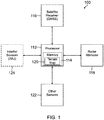
- FIG. 1 illustrates a navigation system 100 according to one embodiment, which can implement the radar altimeter integrity monitoring methods in an aircraft.
- the navigation system 100 generally includes at least one processor 112 operatively coupled with at least one memory unit 114, at least one satellite receiver 116 such as a GNSS receiver in operative communication with processor 112, at least one radar altimeter 118 also in operative communication with processor 112, and a terrain map 120 stored in memory unit 114.
- the navigation system 100 can also include one or more additional sensors 122, such as a barometric altimeter, which provide additional sensor data to processor 112.
- navigation system 100 can be hybridized by also including an inertial navigation system (INS) 124 having one or more inertial sensors that provide inertial data to processor 112.
- INS inertial navigation system
- the inertial sensors are implemented in an inertial measurement unit (IMU), which includes three accelerometers for measuring acceleration in three dimensions and three gyroscopes for measuring angular velocity relative to a reference plane.
- IMU inertial measurement unit
- the present integrity monitoring methods include centralized radar altimeter integrity monitoring, parallel radar altimeter integrity monitoring, and combined radar altimeter integrity monitoring. These approaches are described as follows.
- the centralized radar altimeter integrity monitoring (cRIM) method employs an extended version of the solution separation disclosed in U.S. Patent No. 5,760,737 to Brenner , entitled NAVIGATION SYSTEM WITH SOLUTION SEPARATION APPARATUS FOR DETECTING ACCURACY FAILURES, the disclosure of which is incorporated by reference herein.
- the solution separation computes the protection levels (the integrity information) on the basis of position estimate covariance matrices (accuracy information) of the full-solution and all sub-solutions.
- the full-solution processes all available GNSS measurements, and the sub-solution processes a subset of the GNSS measurements selected according to specified GNSS fault states to be mitigated.
- the solution separation also computes the protection levels on the basis of probabilities of false detection and missed detection, in which user-defined parameters are allocated according to either equal or free allocation schemes.
- the probability of missed detection is related to the probability of hazardous misleading information (HMI) and a priori probability of the faults.
- the cRIM method extends the solution separation by considering one or more radar altimeter measurements as additional satellite measurements.
- the radar altimeter measurement(s) expressed in the navigation (NAV) frame in a GNSS (or hybridized) navigation system it is necessary to assume an available terrain map and transform the radar altimeter measurement into the Earth-Centered-Earth-Fixed (ECEF) coordinate system, i.e., to the coordinate system of GNSS measurements.
- the transformed radar altimeter measurement can be, in principle, then considered as a measurement provided by a satellite located at the ECEF frame origin.
- ⁇ RA is the radar altimeter (RA) measurement (altitude above terrain in NAV frame)
- ⁇ TERMAP is the estimate of the orthogonal distance between the ECEF frame origin and the terrain at the point given by the horizontal position of the aircraft and available terrain map; thus, it depends on the horizontal position provided, for example, by GNSS, which is a random variable.
- the radar altimeter measurement is characterized by a measurement noise description (probability density function or at least the moments; mean and covariance matrix), and a radar altimeter failure probability. These are a given.
- the orthogonal distance estimate is characterized by a distribution with a certain mean and variance (defining accuracy) computed on the basis of horizontal position moments and terrain map properties.
- the orthogonal distance estimate integrity is characterized by a terrain map failure probability given by the map and horizontal position integrity information. The errors affecting the horizontal position estimate, map, and radar altimeter measurement are assumed to be independent.
- the cRIM method requires computation of the transformed radar altimeter measurement characteristics, especially of the orthogonal distance ⁇ TERMAP moments.
- ⁇ HOR is the aircraft horizontal position estimate (e.g., from GNSS navigation system) and map is the terrain map.
- the variance of ⁇ TERMAP is given, in the simplest case, by the map accuracy.
- Moments of the orthogonal distance can be also computed by other techniques for computation of moments of nonlinearly transformed random variables, e.g., by the unscented transformation or by methods based on a numerical integration.
- the radar altimeter measurement and orthogonal distance estimate are assumed to be independent random variables, allowing for straightforward computation of the transformed radar altimeter measurement moments.
- the integrity of the transformed radar altimeter measurement is given by the probability of failure of the radar altimeter, the GNSS (or hybridized) horizontal position navigation information integrity, and information coming from map integrity (according to addition law of probability).
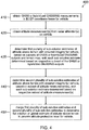
- FIG. 2 is a flow diagram for a method 200 for implementing the centralized radar altimeter integrity monitoring.
- one or more GNSS or hybridized GNSS/INS measurements are obtained in an ECEF coordinate frame for a vehicle (block 210), and one or more altitude measurements are obtained from one or more radar altimeters on the vehicle (block 220).
- the altitude measurement(s) are transformed into the ECEF coordinate frame using a terrain map and a GNSS or hybridized GNSS/INS based position estimate with ensured integrity (block 230).
- a full solution estimate of position is determined for the vehicle, based on the transformed altitude measurement(s) and the GNSS or hybridized GNSS/INS measurements (block 240).
- the method 200 also determines sub-solution estimates of position for the vehicle, based on a subset of the transformed altitude measurement(s) and the GNSS or hybridized GNSS/INS measurements (block 250). Thereafter, the full solution estimate is compared with the sub-solution estimates using statistical analysis (block 260). An altitude protection level for the vehicle is then determined based on a probability of hazardous misleading information and a probability of false detection (block 270).
- the full solution processes all GNSS measurements, all transformed radar altimeter measurements, and additional sensor measurements (e.g., from barometric altimeter and IMU).
- the sub-solutions process a subset of all GNSS and transformed radar altimeter measurements (e.g., by excluding one GNSS or radar altimeter measurement if a single failure is assumed), and additional sensor measurements.
- the computation of the solution separation parameter ( Dn ) and the error parameter ( an ), which are related to the altitude for all sub-solutions, is based on moments of the full solution and sub-solutions.
- the computation of altitude protection level is based on the probability of hazardous misleading information (HMI), the probability of false detection, the probability of satellite failure, the probability of radar altimeter failure (including a map related integrity allocation), and probabilities of wide failures (probabilities that all GNSS and altitude measurements affected by a failure).
- Figure 3 illustrates an exemplary cRIM architecture 300, with a single failure assumption (either one GNSS or one radar altimeter failed).
- the full solution based on all GNSS measurements and radar altimeter measurements is indicated at 310.
- the sub-solutions processing all available measurements of radar altimeters and all but one of the GNSS measurements are indicated at 320a, 320b, 320c, ... 320n. Each sub-solution excludes a different GNSS measurement.
- the sub-solutions processing all GNSS measurements and all but one of the radar altimeter measurements are indicated at 330a, ... 330n. Each sub-solution excludes a different radar altimeter measurement.
- the radar altimeter measurements are supposed to be transformed from the navigation frame to the ECEF frame as described above. Then, all the sub-solutions are statistically compared with the full-solution according to the concept of the solution separation, and it is decided whether all GNSS and radar measurements are healthy or one of the measurements is affected by a failure.
- the parallel radar altimeter integrity monitoring (pRIM) method employs an extended version of the weighted architecture of the high integrity solution separation disclosed in U.S. Patent Publication No. 2015/0145724 to Kana et al. , entitled ARCHITECTURES FOR HIGH INTEGRITY MULTI-CONSTELLATION SOLUTION SEPARATION, the disclosure of which is incorporated by reference herein.
- the high integrity solution separation computes the (local) protection areas independently for several disjunctive sub-groups of satellites, and the resulting protection area is the one somehow overbounding all the local protection areas.
- Each radar altimeter measurement can be considered as a sub-group providing measurement and characteristic of altitude above terrain.
- Figure 4 is a flow diagram for a method 400 for implementing the parallel radar altimeter integrity monitoring.
- one or more GNSS or hybridized GNSS/INS measurements are obtained in an ECEF coordinate frame for a vehicle (block 410), and one or more altitude measurements are obtained from one or more radar altimeters on the vehicle (block 420).
- the method 400 determines a first plurality of sub-solution estimates of altitude above terrain with ensured integrity for the vehicle, based on subsets of the one or more GNSS or hybridized GNSS/INS outputs and a terrain map, with each sub-solution estimate determined based on a respective subset of the one or more GNSS or hybridized GNSS/INS outputs (block 430) as detailed below.
- the method 400 also determines a second plurality of sub-solution estimates of altitude above terrain with ensured integrity for the vehicle, based on a subset of the one or more altitude measurements, with each of these sub-solution estimates being determined based on a respective subset of the one or more altitude measurements (block 440).
- the method 400 then merges the first plurality of sub-solution estimates and second plurality of sub-solution estimates to determine a full solution or global estimate of altitude above terrain, which provides an altitude protection level for the vehicle (block 450).
- FIG. 5 is a block diagram illustrating an exemplary pRIM architecture 500, which includes a GNSS (or hybridized GNSS/INS) navigation system 510, which employs a terrain map 512.
- the navigation system 510 provides a three-dimensional (3D) position estimate of a vehicle and covariance in ECEF, plus integrity information.
- the terrain map 512 includes information on map accuracy plus integrity.
- the outputs from navigation system 510 and terrain map 512 are used to compute the estimate of altitude above terrain at computation block 514, which includes accuracy and integrity information, such as probability density function (or moments) of the horizontal position estimate, related probability of failure (or of hazardous misleading information), and accuracy and integrity of the map.
- the altitude estimate moments depend on the moments of the horizontal position estimate and terrain map properties.
- the probability of failure (or of hazardous misleading information) related to the computed altitude estimate depends on the integrity of the terrain map and the integrity of the navigation system horizontal position estimate, both of which need to be computed as described hereafter.
- One or more radar altimeters 520-1 to 520-n provide measurement or measurements of the altitude above terrain, respectively. For each considered altimeter, information related to its accuracy and integrity is supposed to be known. The statistical description of the radar altimeter measurement noise is available (defining its accuracy), along with the probability of radar altimeter failure (defining its integrity).
- a fusion block 530 which computes overall (or global) altitude along with its accuracy and integrity information, is configured to receive the altitude estimate from computation block 514 (local 1), and the altitude measurements from radar altimeters 520-1 to 520-n (local 2 to local n+1). The fusion block 530 merges the (local) altitude estimate and measurements to produce a global estimate output of altitude above terrain with ensured integrity and accuracy.
- the pRIM method is based on computation of the altitude estimate above terrain and its characteristics (integrity and variance (or other moments) defining altitude estimate accuracy) on the basis of GNSS horizontal position estimate and a terrain map.
- the altitude estimate mean value can be computed in the same way as in the cRIM method discussed previously.
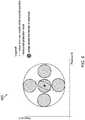
- Figure 6 is a graphical representation 600 of an exemplary pRIM computation of uncertainty ⁇ MAP , HPint 2 .
- Figure 6 shows the mean and covariance matrix of horizontal position, and the HPL.
- the GNSS HPL defines the area used for computation of the uncertainty ⁇ MAP , HPint 2 .
- the computation is based on evaluation (or scanning) of the terrain variability at multiple points in the area computed on the basis of the available map.
- the integrity of the altitude estimate is given by the integrity of the GNSS horizontal position and of the map computed according to the addition law of probability.
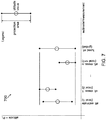
- Figure 7 is a graphical representation 700 of an exemplary pRIM fusion (merging) function.
- Figure 7 shows the altitude and protection level (PL) value for each of an altitude estimate (local 1), and altitude measurements 1 to n (local 2 to local n+1).
- the estimates are fused to produce the global estimate of altitude above terrain, for example as illustrated in Figure 7 .
- the global altitude estimate mean can be computed as a (weighted) average of the local means.
- the global covariance matrix can be then computed as a (weighted) sum of local variances (assuming mutual independence of local estimates).
- the global PL can be determined as the protection level overbounding all the local PLs as it can be shown that: p HMI fused ⁇ p HMI estim ⁇ HMI RAmeas , 1 ⁇ ... ⁇ p HMI RAmeas , n
- the pRIM architecture is composed of local blocks providing altitude integration each with ensured integrity. Therefore, the global output is also with ensured integrity and there is no need to detect failed measurements. Detection, if any, is performed in local estimators.
- the cRIM method provides estimates with better accuracy than pRIM, while the pRIM method allows for trade-off between accuracy and integrity.
- a combined radar altimeter integrity monitoring architecture (combRIM) is provided, which combines characteristic properties of the cRIM and pRIM approaches.
- the combRIM method is in principle solution separation but just in the altitude domain.
- all available radar altimeter measurements and (possibly) altitude estimates are processed (e.g., by averaging filter with or without weights defined by the measurement noise variances) and a global (full-solution) estimate of altitude above terrain is computed.
- a set of sub-solutions is created (based on faults definition) and a set of sub-solutions estimates of altitude above terrain is computed.
- a full solution and sub-solution estimates are statistically compared, and protection level for altitude above terrain is computed for required probabilities of missed and false detection.
- FIG 8 is a flow diagram for a method 800 for implementing the combRIM method.
- two or more altitude measurements are obtained from one or more radar altimeters (or other sensors) on a vehicle (block 810).
- the method 800 determines a full solution estimate of altitude above terrain for the vehicle based on the two or more altitude measurements (block 820), and determines two or more sub-solution estimates of altitude above terrain for the vehicle based on a subset of the two or more altitude measurements (block 830).
- the method 800 compares the full solution estimate with the two or more sub-solution estimates using statistical analysis (block 840).
- An altitude protection level for the vehicle is then determined based on a probability of hazardous misleading information and a probability of false detection (block 850).
- the combRIM approach can be implemented with or without the GNSS (or hybridized GNSS/INS) system and terrain map based altitude above terrain. At least two radar altimeter measurements or estimates are needed for detection capability, while at least three radar altimeter measurements or estimates are needed for exclusion capability.
- integrity monitoring with fault detection can be done according to solution separation.
- integrity monitoring with fault detection and exclusion can be done according to solution separation.
- a computer or processor used in the present system and method can be implemented using software, firmware, hardware, or any appropriate combination thereof, as known to one of skill in the art. These may be supplemented by, or incorporated in, specially-designed application-specific integrated circuits (ASICs) or field programmable gate arrays (FPGAs).
- ASICs application-specific integrated circuits
- FPGAs field programmable gate arrays
- the computer or processor can also include functions with software programs, firmware, or other computer readable instructions for carrying out various process tasks, calculations, and control functions used in the present method and system.
- the present methods can be implemented by computer executable instructions, such as program modules or components, which are executed by at least one processor.
- program modules include routines, programs, objects, data components, data structures, algorithms, and the like, which perform particular tasks or implement particular abstract data types.
- Instructions for carrying out the various process tasks, calculations, and generation of other data used in the operation of the methods described herein can be implemented in software, firmware, or other computer-readable or processor-readable instructions. These instructions are typically stored on any appropriate computer program product that includes a computer readable medium used for storage of computer readable instructions or data structures. Such a computer readable medium can be any available media that can be accessed by a general purpose or special purpose computer or processor, or any programmable logic device.
- Suitable processor-readable media may include storage or memory media such as magnetic or optical media.
- storage or memory media may include conventional hard disks, compact disks, DVDs, Blu-ray discs, or other optical storage disks; volatile or non-volatile media such as Random Access Memory (RAM); Read Only Memory (ROM), Electrically Erasable Programmable ROM (EEPROM), flash memory, and the like; or any other media that can be used to carry or store desired program code in the form of computer executable instructions or data structures.
- RAM Random Access Memory
- ROM Read Only Memory
- EEPROM Electrically Erasable Programmable ROM
- flash memory and the like
- any other media that can be used to carry or store desired program code in the form of computer executable instructions or data structures.
- Example 1 includes a method for radar altimeter integrity monitoring, the method comprising: obtaining one or more global navigation satellite system (GNSS) measurements, or one or more hybridized GNSS/inertial navigation system (INS) measurements, in an earth-centered-earth-fixed (ECEF) coordinate frame for a vehicle; obtaining one or more altitude measurements from one or more radar altimeters on the vehicle; transforming the one or more altitude measurements into the ECEF coordinate frame using a terrain map and a GNSS or hybridized GNSS/INS based position estimate with ensured integrity; determining a full solution estimate of position for the vehicle based on the transformed one or more altitude measurements, and the one or more GNSS or hybridized GNSS/INS measurements; determining one or more sub-solution estimates of position for the vehicle based on a subset of the transformed one or more altitude measurements, and the one or more GNSS or hybridized GNSS/INS measurements; comparing the full solution estimate with the one or more sub-solution estimates using statistical analysis; and determining an altitude
- Example 2 includes a navigation system comprising: a processor in a vehicle; a memory unit operatively coupled with the processor, wherein a terrain map is stored in the memory unit; a GNSS receiver operatively coupled with the processor; and one or more radar altimeters operatively coupled with the processor; wherein the processor is configured to execute processor readable instructions to perform the method for radar altimeter integrity monitoring according to Example 1.
- Example 3 includes the navigation system of Example 2, further comprising a plurality of inertial sensors operatively coupled with the processor and configured to provide inertial data to the processor.
- Example 4 includes the navigation system of Example 3, wherein the inertial sensors are implemented in an inertial measurement unit (IMU).
- IMU inertial measurement unit
- Example 5 includes the navigation system of any of Examples 2-4, further comprising a barometric altimeter operatively coupled with the processor.
- Example 6 includes a computer program product comprising a non-transitory computer readable medium having instructions stored thereon executable by a processor to perform the method for radar altimeter integrity monitoring according to Example 1.
- Example 7 includes a method for radar altimeter integrity monitoring, the method comprising: obtaining one or more GNSS measurements, or one or more hybridized GNSS/INS measurements, in an ECEF coordinate frame for a vehicle; obtaining one or more altitude measurements from one or more radar altimeters on the vehicle; determining a first plurality of sub-solution estimates of altitude above terrain with ensured (given) integrity for the vehicle, based on subsets of the one or more GNSS or hybridized GNSS/INS outputs and a terrain map, each sub-solution estimate in the first plurality of sub-solution estimates determined based on a respective sub-set of the one or more GNSS or hybridized GNSS/INS outputs; determining a second plurality of sub-solution estimates of altitude above terrain with ensured (given) integrity for the vehicle, based on a subset of the one or more altitude measurements, each sub-solution estimate in the second plurality of sub-solution estimates determined based on a respective subset of the one or more altitude measurements
- Example 8 includes a navigation system comprising: a processor in a vehicle; a memory unit operatively coupled with the processor, wherein a terrain map is stored in the memory unit; a GNSS receiver operatively coupled with the processor; and one or more radar altimeters operatively coupled with the processor; wherein the processor is configured to execute processor readable instructions to perform the method for radar altimeter integrity monitoring according to Example 7.
- Example 9 includes the navigation system of Example 8, further comprising a plurality of inertial sensors operatively coupled with the processor and configured to provide inertial data to the processor.
- Example 10 includes the navigation system of Example 9, wherein the inertial sensors are implemented in an IMU.
- Example 11 includes the navigation system of any of Examples 8-10, further comprising a barometric altimeter operatively coupled with the processor.
- Example 12 includes a computer program product comprising a non-transitory computer readable medium having instructions stored thereon executable by a processor to perform the method for radar altimeter integrity monitoring according to Example 7.
- Example 13 includes a method for radar altimeter integrity monitoring, the method comprising: obtaining two or more altitude measurements from one or more radar altimeters on a vehicle; determining a full solution estimate of altitude above terrain for the vehicle based on the two or more altitude measurements; determining two or more sub-solution estimates of altitude above terrain for the vehicle based on a subset of the two or more altitude measurements; comparing the full solution estimate with the two or more sub-solution estimates using statistical analysis; and determining an altitude protection level for the vehicle based on a probability of hazardous misleading information and a probability of false detection.
- Example 14 includes the method of Example 13, further comprising: obtaining one or more GNSS measurements, or one or more hybridized GNSS/INS measurements, in an ECEF coordinate frame for the vehicle; and transforming the one or more altitude measurements into the ECEF coordinate frame using a terrain map and a GNSS or hybridized GNSS/INS based position estimate with ensured integrity.
- Example 15 includes a navigation system comprising: a processor in a vehicle; and one or more radar altimeters operatively coupled with the processor; wherein the processor is configured to execute processor readable instructions to perform the method for radar altimeter integrity monitoring according to Example 13.
- Example 16 includes a navigation system comprising: a processor in a vehicle; a memory unit operatively coupled with the processor, wherein a terrain map is stored in the memory unit; a GNSS receiver operatively coupled with the processor; and one or more radar altimeters operatively coupled with the processor; wherein the processor is configured to execute processor readable instructions to perform the method for radar altimeter integrity monitoring according to Example 14.
- Example 17 includes the navigation system of Example 16, further comprising a plurality of inertial sensors operatively coupled with the processor and configured to provide inertial data to the processor.
- Example 18 includes the navigation system of Example 17, wherein the inertial sensors are implemented in an IMU.
- Example 19 includes a computer program product comprising a non-transitory computer readable medium having instructions stored thereon executable by a processor to perform the method for radar altimeter integrity monitoring according to Example 13.
Abstract
Description
- A radar altimeter is an aircraft sensor that measures altitude above terrain by transmitting a radio signal and receiving a reflection of the signal from a terrain surface. The radar altimeter measured altitude is an important piece of information used by a pilot and onboard systems (e.g., an autopilot system) during the various phases of flight, including approach and landing.
- Currently, an aircraft is usually equipped with several radar altimeters. Typically, the measurements from all radar altimeters are processed (e.g., compared to each other) and the resulting value of the altitude is provided to onboard systems and the pilot. However, the altitude is provided without any information related to its accuracy or integrity, which limits utilization of radar altimeter measurements in envisioned applications related to more autonomous aircraft.
- Accuracy and integrity of the navigation information (horizontal and vertical position) provided by a Global Navigation Satellite System (GNSS) based navigation system or hybridized Global Navigation Satellite System and Inertial Navigation System (GNSS/INS) based navigation system with respect to possible faults of GNSS satellites has been solved since the advent of GNSS-based navigation systems. However, accuracy and integrity of the navigation information provided by a navigation system utilizing radar altimeters with respect to possible faults of the radar altimeter has not been addressed yet.
- Methods for radar altimeter integrity monitoring are provided. One method comprises obtaining one or more global navigation satellite system (GNSS) measurements, or one or more hybridized GNSS/inertial navigation system (INS) measurements, in an earth-centered-earth-fixed (ECEF) coordinate frame for a vehicle; obtaining one or more altitude measurements from one or more radar altimeters on the vehicle; transforming the one or more altitude measurements into the ECEF coordinate frame using a terrain map and a GNSS or hybridized GNSS/INS based position estimate with ensured integrity; determining a full solution estimate of position for the vehicle based on the transformed one or more altitude measurements, and the one or more GNSS or hybridized GNSS/INS measurements; determining one or more sub-solution estimates of position for the vehicle based on a subset of the transformed one or more altitude measurements, and the one or more GNSS or hybridized GNSS/INS measurements; comparing the full solution estimate with the one or more sub-solution estimates using statistical analysis; and determining an altitude protection level for the vehicle based on a probability of hazardous misleading information and a probability of false detection.
- Features of the present invention will become apparent to those skilled in the art from the following description with reference to the drawings. Understanding that the drawings depict only typical embodiments and are not therefore to be considered limiting in scope, the invention will be described with additional specificity and detail through the use of the accompanying drawings, in which:
-
Figure 1 is a block diagram of a navigation system according to one embodiment, which can implement radar altimeter integrity monitoring in a vehicle; -
Figure 2 is a flow diagram for a method of implementing centralized radar altimeter integrity monitoring for a vehicle; -
Figure 3 is a schematic diagram illustrating an exemplary architecture for implementing centralized radar altimeter integrity monitoring for a vehicle; -
Figure 4 is a flow diagram for a method of implementing parallel radar altimeter integrity monitoring for a vehicle; -
Figure 5 is a block diagram illustrating an exemplary architecture for implementing the parallel radar altimeter integrity monitoring for a vehicle; -
Figure 6 is a graphical representation of an exemplary computation of altitude characteristics for the parallel radar altimeter integrity monitoring; -
Figure 7 is a graphical representation of a fusion function in the parallel radar altimeter integrity monitoring for a vehicle; and -
Figure 8 is a flow diagram for a method of implementing combined radar altimeter integrity monitoring for a vehicle. - In the following detailed description, embodiments are described in sufficient detail to enable those skilled in the art to practice the invention. It is to be understood that other embodiments may be utilized without departing from the scope of the invention. The following detailed description is, therefore, not to be taken in a limiting sense.
- Altitude above the ground or terrain (i.e., the clearance) information with assured accuracy and integrity is an important component of envisioned aircraft avionics architecture. Accordingly, systems and methods for integrity monitoring of radar altimeters are described herein, which allow for computation of the accuracy (e.g., in terms of the standard deviation) and integrity (protection level) of the altitude above terrain measured by the radar altimeters and possibly other sensors (e.g., global navigation satellite system (GNSS)).
- The proposed integrity monitoring methods are based on a statistical comparison of the radar altimeter measurements with outputs of other navigation systems and sensors, and in principle, offer a trade-off between accuracy and integrity. The integrity monitoring methods are based on the concept of solution separation integrity monitoring.
- Further details of the present systems and methods are described hereafter with reference to the drawings.
-
Figure 1 illustrates anavigation system 100 according to one embodiment, which can implement the radar altimeter integrity monitoring methods in an aircraft. Thenavigation system 100 generally includes at least oneprocessor 112 operatively coupled with at least onememory unit 114, at least onesatellite receiver 116 such as a GNSS receiver in operative communication withprocessor 112, at least oneradar altimeter 118 also in operative communication withprocessor 112, and aterrain map 120 stored inmemory unit 114. Thenavigation system 100 can also include one or moreadditional sensors 122, such as a barometric altimeter, which provide additional sensor data toprocessor 112. - In an alternative embodiment,
navigation system 100 can be hybridized by also including an inertial navigation system (INS) 124 having one or more inertial sensors that provide inertial data toprocessor 112. In one embodiment, the inertial sensors are implemented in an inertial measurement unit (IMU), which includes three accelerometers for measuring acceleration in three dimensions and three gyroscopes for measuring angular velocity relative to a reference plane. - The present integrity monitoring methods include centralized radar altimeter integrity monitoring, parallel radar altimeter integrity monitoring, and combined radar altimeter integrity monitoring. These approaches are described as follows.
- The centralized radar altimeter integrity monitoring (cRIM) method employs an extended version of the solution separation disclosed in
U.S. Patent No. 5,760,737 to Brenner , entitled NAVIGATION SYSTEM WITH SOLUTION SEPARATION APPARATUS FOR DETECTING ACCURACY FAILURES, the disclosure of which is incorporated by reference herein. In principle, the solution separation computes the protection levels (the integrity information) on the basis of position estimate covariance matrices (accuracy information) of the full-solution and all sub-solutions. The full-solution processes all available GNSS measurements, and the sub-solution processes a subset of the GNSS measurements selected according to specified GNSS fault states to be mitigated. The solution separation also computes the protection levels on the basis of probabilities of false detection and missed detection, in which user-defined parameters are allocated according to either equal or free allocation schemes. The probability of missed detection is related to the probability of hazardous misleading information (HMI) and a priori probability of the faults. - The cRIM method extends the solution separation by considering one or more radar altimeter measurements as additional satellite measurements. In order to be able to process the radar altimeter measurement(s) expressed in the navigation (NAV) frame in a GNSS (or hybridized) navigation system, it is necessary to assume an available terrain map and transform the radar altimeter measurement into the Earth-Centered-Earth-Fixed (ECEF) coordinate system, i.e., to the coordinate system of GNSS measurements. The transformed radar altimeter measurement can be, in principle, then considered as a measurement provided by a satellite located at the ECEF frame origin.
- The transformed radar altimeter measurement is given by the following equation:

- The radar altimeter measurement is characterized by a measurement noise description (probability density function or at least the moments; mean and covariance matrix), and a radar altimeter failure probability. These are a given. The orthogonal distance estimate is characterized by a distribution with a certain mean and variance (defining accuracy) computed on the basis of horizontal position moments and terrain map properties. The orthogonal distance estimate integrity is characterized by a terrain map failure probability given by the map and horizontal position integrity information. The errors affecting the horizontal position estimate, map, and radar altimeter measurement are assumed to be independent.
- The cRIM method requires computation of the transformed radar altimeter measurement characteristics, especially of the orthogonal distance ρTERMAP moments. The mean value can be computed as:

- The radar altimeter measurement and orthogonal distance estimate are assumed to be independent random variables, allowing for straightforward computation of the transformed radar altimeter measurement moments. The integrity of the transformed radar altimeter measurement is given by the probability of failure of the radar altimeter, the GNSS (or hybridized) horizontal position navigation information integrity, and information coming from map integrity (according to addition law of probability).
-
Figure 2 is a flow diagram for amethod 200 for implementing the centralized radar altimeter integrity monitoring. Initially, one or more GNSS or hybridized GNSS/INS measurements are obtained in an ECEF coordinate frame for a vehicle (block 210), and one or more altitude measurements are obtained from one or more radar altimeters on the vehicle (block 220). The altitude measurement(s) are transformed into the ECEF coordinate frame using a terrain map and a GNSS or hybridized GNSS/INS based position estimate with ensured integrity (block 230). A full solution estimate of position is determined for the vehicle, based on the transformed altitude measurement(s) and the GNSS or hybridized GNSS/INS measurements (block 240). Themethod 200 also determines sub-solution estimates of position for the vehicle, based on a subset of the transformed altitude measurement(s) and the GNSS or hybridized GNSS/INS measurements (block 250). Thereafter, the full solution estimate is compared with the sub-solution estimates using statistical analysis (block 260). An altitude protection level for the vehicle is then determined based on a probability of hazardous misleading information and a probability of false detection (block 270). - In the cRIM method, the full solution processes all GNSS measurements, all transformed radar altimeter measurements, and additional sensor measurements (e.g., from barometric altimeter and IMU). The sub-solutions process a subset of all GNSS and transformed radar altimeter measurements (e.g., by excluding one GNSS or radar altimeter measurement if a single failure is assumed), and additional sensor measurements.
- The computation of the solution separation parameter (Dn) and the error parameter (an), which are related to the altitude for all sub-solutions, is based on moments of the full solution and sub-solutions. The computation of altitude protection level is based on the probability of hazardous misleading information (HMI), the probability of false detection, the probability of satellite failure, the probability of radar altimeter failure (including a map related integrity allocation), and probabilities of wide failures (probabilities that all GNSS and altitude measurements affected by a failure).
-
Figure 3 illustrates an exemplarycRIM architecture 300, with a single failure assumption (either one GNSS or one radar altimeter failed). The full solution based on all GNSS measurements and radar altimeter measurements is indicated at 310. The sub-solutions processing all available measurements of radar altimeters and all but one of the GNSS measurements are indicated at 320a, 320b, 320c, ... 320n. Each sub-solution excludes a different GNSS measurement. The sub-solutions processing all GNSS measurements and all but one of the radar altimeter measurements are indicated at 330a, ... 330n. Each sub-solution excludes a different radar altimeter measurement. Note that the radar altimeter measurements are supposed to be transformed from the navigation frame to the ECEF frame as described above. Then, all the sub-solutions are statistically compared with the full-solution according to the concept of the solution separation, and it is decided whether all GNSS and radar measurements are healthy or one of the measurements is affected by a failure. - The parallel radar altimeter integrity monitoring (pRIM) method employs an extended version of the weighted architecture of the high integrity solution separation disclosed in
U.S. Patent Publication No. 2015/0145724 to Kana et al. , entitled ARCHITECTURES FOR HIGH INTEGRITY MULTI-CONSTELLATION SOLUTION SEPARATION, the disclosure of which is incorporated by reference herein. In principle, the high integrity solution separation computes the (local) protection areas independently for several disjunctive sub-groups of satellites, and the resulting protection area is the one somehow overbounding all the local protection areas. Each radar altimeter measurement can be considered as a sub-group providing measurement and characteristic of altitude above terrain. -
Figure 4 is a flow diagram for amethod 400 for implementing the parallel radar altimeter integrity monitoring. Initially, one or more GNSS or hybridized GNSS/INS measurements are obtained in an ECEF coordinate frame for a vehicle (block 410), and one or more altitude measurements are obtained from one or more radar altimeters on the vehicle (block 420). Themethod 400 determines a first plurality of sub-solution estimates of altitude above terrain with ensured integrity for the vehicle, based on subsets of the one or more GNSS or hybridized GNSS/INS outputs and a terrain map, with each sub-solution estimate determined based on a respective subset of the one or more GNSS or hybridized GNSS/INS outputs (block 430) as detailed below. Themethod 400 also determines a second plurality of sub-solution estimates of altitude above terrain with ensured integrity for the vehicle, based on a subset of the one or more altitude measurements, with each of these sub-solution estimates being determined based on a respective subset of the one or more altitude measurements (block 440). Themethod 400 then merges the first plurality of sub-solution estimates and second plurality of sub-solution estimates to determine a full solution or global estimate of altitude above terrain, which provides an altitude protection level for the vehicle (block 450). -
Figure 5 is a block diagram illustrating an exemplarypRIM architecture 500, which includes a GNSS (or hybridized GNSS/INS)navigation system 510, which employs aterrain map 512. Thenavigation system 510 provides a three-dimensional (3D) position estimate of a vehicle and covariance in ECEF, plus integrity information. Theterrain map 512 includes information on map accuracy plus integrity. The outputs fromnavigation system 510 andterrain map 512 are used to compute the estimate of altitude above terrain atcomputation block 514, which includes accuracy and integrity information, such as probability density function (or moments) of the horizontal position estimate, related probability of failure (or of hazardous misleading information), and accuracy and integrity of the map. Thus, the altitude estimate moments depend on the moments of the horizontal position estimate and terrain map properties. The probability of failure (or of hazardous misleading information) related to the computed altitude estimate depends on the integrity of the terrain map and the integrity of the navigation system horizontal position estimate, both of which need to be computed as described hereafter. - One or more radar altimeters 520-1 to 520-n provide measurement or measurements of the altitude above terrain, respectively. For each considered altimeter, information related to its accuracy and integrity is supposed to be known. The statistical description of the radar altimeter measurement noise is available (defining its accuracy), along with the probability of radar altimeter failure (defining its integrity).
- A
fusion block 530, which computes overall (or global) altitude along with its accuracy and integrity information, is configured to receive the altitude estimate from computation block 514 (local 1), and the altitude measurements from radar altimeters 520-1 to 520-n (local 2 to local n+1). Thefusion block 530 merges the (local) altitude estimate and measurements to produce a global estimate output of altitude above terrain with ensured integrity and accuracy. - The pRIM method is based on computation of the altitude estimate above terrain and its characteristics (integrity and variance (or other moments) defining altitude estimate accuracy) on the basis of GNSS horizontal position estimate and a terrain map. The altitude estimate mean value can be computed in the same way as in the cRIM method discussed previously. The variance can be computed as:


-
Figure 6 is agraphical representation 600 of an exemplary pRIM computation of uncertainty
Figure 6 shows the mean and covariance matrix of horizontal position, and the HPL. The GNSS HPL defines the area used for computation of the uncertainty
-
Figure 7 is agraphical representation 700 of an exemplary pRIM fusion (merging) function.Figure 7 shows the altitude and protection level (PL) value for each of an altitude estimate (local 1), andaltitude measurements 1 to n (local 2 to local n+1). The estimates are fused to produce the global estimate of altitude above terrain, for example as illustrated inFigure 7 . In this example, the global altitude estimate mean can be computed as a (weighted) average of the local means. The global covariance matrix can be then computed as a (weighted) sum of local variances (assuming mutual independence of local estimates). The global PL can be determined as the protection level overbounding all the local PLs as it can be shown that:
- In general, the cRIM method provides estimates with better accuracy than pRIM, while the pRIM method allows for trade-off between accuracy and integrity.
- In another embodiment, a combined radar altimeter integrity monitoring architecture (combRIM) is provided, which combines characteristic properties of the cRIM and pRIM approaches. The combRIM method is in principle solution separation but just in the altitude domain.
- In the combRIM method, all available radar altimeter measurements and (possibly) altitude estimates are processed (e.g., by averaging filter with or without weights defined by the measurement noise variances) and a global (full-solution) estimate of altitude above terrain is computed. A set of sub-solutions is created (based on faults definition) and a set of sub-solutions estimates of altitude above terrain is computed. A full solution and sub-solution estimates are statistically compared, and protection level for altitude above terrain is computed for required probabilities of missed and false detection.
-
Figure 8 is a flow diagram for amethod 800 for implementing the combRIM method. Initially, two or more altitude measurements are obtained from one or more radar altimeters (or other sensors) on a vehicle (block 810). Themethod 800 determines a full solution estimate of altitude above terrain for the vehicle based on the two or more altitude measurements (block 820), and determines two or more sub-solution estimates of altitude above terrain for the vehicle based on a subset of the two or more altitude measurements (block 830). Themethod 800 then compares the full solution estimate with the two or more sub-solution estimates using statistical analysis (block 840). An altitude protection level for the vehicle is then determined based on a probability of hazardous misleading information and a probability of false detection (block 850). - The combRIM approach can be implemented with or without the GNSS (or hybridized GNSS/INS) system and terrain map based altitude above terrain. At least two radar altimeter measurements or estimates are needed for detection capability, while at least three radar altimeter measurements or estimates are needed for exclusion capability.
- In some embodiments, if two radar altimeter measurements are available, then integrity monitoring with fault detection can be done according to solution separation.
- In another embodiment, if two radar altimeter measurements and one altitude estimate (based on terrain map aided GNSS/INS system) is available, then integrity monitoring with fault detection and exclusion can be done according to solution separation.
- A computer or processor used in the present system and method can be implemented using software, firmware, hardware, or any appropriate combination thereof, as known to one of skill in the art. These may be supplemented by, or incorporated in, specially-designed application-specific integrated circuits (ASICs) or field programmable gate arrays (FPGAs). The computer or processor can also include functions with software programs, firmware, or other computer readable instructions for carrying out various process tasks, calculations, and control functions used in the present method and system.
- The present methods can be implemented by computer executable instructions, such as program modules or components, which are executed by at least one processor. Generally, program modules include routines, programs, objects, data components, data structures, algorithms, and the like, which perform particular tasks or implement particular abstract data types.
- Instructions for carrying out the various process tasks, calculations, and generation of other data used in the operation of the methods described herein can be implemented in software, firmware, or other computer-readable or processor-readable instructions. These instructions are typically stored on any appropriate computer program product that includes a computer readable medium used for storage of computer readable instructions or data structures. Such a computer readable medium can be any available media that can be accessed by a general purpose or special purpose computer or processor, or any programmable logic device.
- Suitable processor-readable media may include storage or memory media such as magnetic or optical media. For example, storage or memory media may include conventional hard disks, compact disks, DVDs, Blu-ray discs, or other optical storage disks; volatile or non-volatile media such as Random Access Memory (RAM); Read Only Memory (ROM), Electrically Erasable Programmable ROM (EEPROM), flash memory, and the like; or any other media that can be used to carry or store desired program code in the form of computer executable instructions or data structures.
- Example 1 includes a method for radar altimeter integrity monitoring, the method comprising: obtaining one or more global navigation satellite system (GNSS) measurements, or one or more hybridized GNSS/inertial navigation system (INS) measurements, in an earth-centered-earth-fixed (ECEF) coordinate frame for a vehicle; obtaining one or more altitude measurements from one or more radar altimeters on the vehicle; transforming the one or more altitude measurements into the ECEF coordinate frame using a terrain map and a GNSS or hybridized GNSS/INS based position estimate with ensured integrity; determining a full solution estimate of position for the vehicle based on the transformed one or more altitude measurements, and the one or more GNSS or hybridized GNSS/INS measurements; determining one or more sub-solution estimates of position for the vehicle based on a subset of the transformed one or more altitude measurements, and the one or more GNSS or hybridized GNSS/INS measurements; comparing the full solution estimate with the one or more sub-solution estimates using statistical analysis; and determining an altitude protection level for the vehicle based on a probability of hazardous misleading information and a probability of false detection.
- Example 2 includes a navigation system comprising: a processor in a vehicle; a memory unit operatively coupled with the processor, wherein a terrain map is stored in the memory unit; a GNSS receiver operatively coupled with the processor; and one or more radar altimeters operatively coupled with the processor; wherein the processor is configured to execute processor readable instructions to perform the method for radar altimeter integrity monitoring according to Example 1.
- Example 3 includes the navigation system of Example 2, further comprising a plurality of inertial sensors operatively coupled with the processor and configured to provide inertial data to the processor.
- Example 4 includes the navigation system of Example 3, wherein the inertial sensors are implemented in an inertial measurement unit (IMU).
- Example 5 includes the navigation system of any of Examples 2-4, further comprising a barometric altimeter operatively coupled with the processor.
- Example 6 includes a computer program product comprising a non-transitory computer readable medium having instructions stored thereon executable by a processor to perform the method for radar altimeter integrity monitoring according to Example 1.
- Example 7 includes a method for radar altimeter integrity monitoring, the method comprising: obtaining one or more GNSS measurements, or one or more hybridized GNSS/INS measurements, in an ECEF coordinate frame for a vehicle; obtaining one or more altitude measurements from one or more radar altimeters on the vehicle; determining a first plurality of sub-solution estimates of altitude above terrain with ensured (given) integrity for the vehicle, based on subsets of the one or more GNSS or hybridized GNSS/INS outputs and a terrain map, each sub-solution estimate in the first plurality of sub-solution estimates determined based on a respective sub-set of the one or more GNSS or hybridized GNSS/INS outputs; determining a second plurality of sub-solution estimates of altitude above terrain with ensured (given) integrity for the vehicle, based on a subset of the one or more altitude measurements, each sub-solution estimate in the second plurality of sub-solution estimates determined based on a respective subset of the one or more altitude measurements; and merging the first plurality of sub-solution estimates and the second plurality of sub-solution estimates to determine a full solution or global estimate of altitude above terrain, which provides an altitude protection level for the vehicle.
- Example 8 includes a navigation system comprising: a processor in a vehicle; a memory unit operatively coupled with the processor, wherein a terrain map is stored in the memory unit; a GNSS receiver operatively coupled with the processor; and one or more radar altimeters operatively coupled with the processor; wherein the processor is configured to execute processor readable instructions to perform the method for radar altimeter integrity monitoring according to Example 7.
- Example 9 includes the navigation system of Example 8, further comprising a plurality of inertial sensors operatively coupled with the processor and configured to provide inertial data to the processor.
- Example 10 includes the navigation system of Example 9, wherein the inertial sensors are implemented in an IMU.
- Example 11 includes the navigation system of any of Examples 8-10, further comprising a barometric altimeter operatively coupled with the processor.
- Example 12 includes a computer program product comprising a non-transitory computer readable medium having instructions stored thereon executable by a processor to perform the method for radar altimeter integrity monitoring according to Example 7.
- Example 13 includes a method for radar altimeter integrity monitoring, the method comprising: obtaining two or more altitude measurements from one or more radar altimeters on a vehicle; determining a full solution estimate of altitude above terrain for the vehicle based on the two or more altitude measurements; determining two or more sub-solution estimates of altitude above terrain for the vehicle based on a subset of the two or more altitude measurements; comparing the full solution estimate with the two or more sub-solution estimates using statistical analysis; and determining an altitude protection level for the vehicle based on a probability of hazardous misleading information and a probability of false detection.
- Example 14 includes the method of Example 13, further comprising: obtaining one or more GNSS measurements, or one or more hybridized GNSS/INS measurements, in an ECEF coordinate frame for the vehicle; and transforming the one or more altitude measurements into the ECEF coordinate frame using a terrain map and a GNSS or hybridized GNSS/INS based position estimate with ensured integrity.
- Example 15 includes a navigation system comprising: a processor in a vehicle; and one or more radar altimeters operatively coupled with the processor; wherein the processor is configured to execute processor readable instructions to perform the method for radar altimeter integrity monitoring according to Example 13.
- Example 16 includes a navigation system comprising: a processor in a vehicle; a memory unit operatively coupled with the processor, wherein a terrain map is stored in the memory unit; a GNSS receiver operatively coupled with the processor; and one or more radar altimeters operatively coupled with the processor; wherein the processor is configured to execute processor readable instructions to perform the method for radar altimeter integrity monitoring according to Example 14.
- Example 17 includes the navigation system of Example 16, further comprising a plurality of inertial sensors operatively coupled with the processor and configured to provide inertial data to the processor.
- Example 18 includes the navigation system of Example 17, wherein the inertial sensors are implemented in an IMU.
- Example 19 includes a computer program product comprising a non-transitory computer readable medium having instructions stored thereon executable by a processor to perform the method for radar altimeter integrity monitoring according to Example 13.
- The present invention may be embodied in other specific forms without departing from its essential characteristics. The described embodiments are to be considered in all respects only as illustrative and not restrictive. The scope of the invention is therefore indicated by the appended claims rather than by the foregoing description. All changes that come within the meaning and range of equivalency of the claims are to be embraced within their scope.
Claims (10)
- A method for radar altimeter integrity monitoring, the method comprising:obtaining one or more global navigation satellite system (GNSS) measurements, or one or more hybridized GNSS/inertial navigation system (INS) measurements, in an earth-centered-earth-fixed (ECEF) coordinate frame for a vehicle;obtaining one or more altitude measurements from one or more radar altimeters on the vehicle;transforming the one or more altitude measurements into the ECEF coordinate frame using a terrain map and a GNSS or hybridized GNSS/INS based position estimate with ensured integrity;determining a full solution estimate of position for the vehicle based on the transformed one or more altitude measurements, and the one or more GNSS or hybridized GNSS/INS measurements;determining one or more sub-solution estimates of position for the vehicle based on a subset of the transformed one or more altitude measurements, and the one or more GNSS or hybridized GNSS/INS measurements;comparing the full solution estimate with the one or more sub-solution estimates using statistical analysis; anddetermining an altitude protection level for the vehicle based on a probability of hazardous misleading information and a probability of false detection.
- A navigation system, comprising:a processor in a vehicle;a memory unit operatively coupled with the processor, wherein a terrain map is stored in the memory unit;a global navigation satellite system (GNSS) receiver operatively coupled with the processor; andone or more radar altimeters operatively coupled with the processor;wherein the processor is configured to execute processor readable instructions to perform the method for radar altimeter integrity monitoring according to claim 1.
- The navigation system of claim 2, further comprising a plurality of inertial sensors operatively coupled with the processor and configured to provide inertial data to the processor.
- The navigation system of claim 2, further comprising a barometric altimeter operatively coupled with the processor.
- A computer program product, comprising:a non-transitory computer readable medium having instructions stored thereon executable by a processor to perform the method for radar altimeter integrity monitoring according to claim 1.
- A method for radar altimeter integrity monitoring, the method comprising:obtaining one or more global navigation satellite system (GNSS) measurements, or one or more hybridized GNSS/inertial navigation system (INS) measurements, in an earth-centered-earth-fixed (ECEF) coordinate frame for a vehicle;obtaining one or more altitude measurements from one or more radar altimeters on the vehicle;determining a first plurality of sub-solution estimates of altitude above terrain with ensured (given) integrity for the vehicle, based on subsets of the one or more GNSS or hybridized GNSS/INS outputs and a terrain map, each sub-solution estimate in the first plurality of sub-solution estimates determined based on a respective sub-set of the one or more GNSS or hybridized GNSS/INS outputs;determining a second plurality of sub-solution estimates of altitude above terrain with ensured (given) integrity for the vehicle, based on a subset of the one or more altitude measurements, each sub-solution estimate in the second plurality of sub-solution estimates determined based on a respective subset of the one or more altitude measurements; andmerging the first plurality of sub-solution estimates and the second plurality of sub-solution estimates to determine a full solution or global estimate of altitude above terrain, which provides an altitude protection level for the vehicle.
- A navigation system, comprising:a processor in a vehicle;a memory unit operatively coupled with the processor, wherein a terrain map is stored in the memory unit;a global navigation satellite system (GNSS) receiver operatively coupled with the processor; andone or more radar altimeters operatively coupled with the processor;wherein the processor is configured to execute processor readable instructions to perform the method for radar altimeter integrity monitoring according to claim 6.
- A computer program product, comprising:a non-transitory computer readable medium having instructions stored thereon executable by a processor to perform the method for radar altimeter integrity monitoring according to claim 6.
- A method for radar altimeter integrity monitoring, the method comprising:obtaining two or more altitude measurements from one or more radar altimeters on a vehicle;determining a full solution estimate of altitude above terrain for the vehicle based on the two or more altitude measurements;determining two or more sub-solution estimates of altitude above terrain for the vehicle based on a subset of the two or more altitude measurements;comparing the full solution estimate with the two or more sub-solution estimates using statistical analysis; anddetermining an altitude protection level for the vehicle based on a probability of hazardous misleading information and a probability of false detection.
- The method of claim 9, further comprising:obtaining one or more global navigation satellite system (GNSS) measurements, or one or more hybridized GNSS/inertial navigation system (INS) measurements, in an earth-centered-earth-fixed (ECEF) coordinate frame for the vehicle; andtransforming the one or more altitude measurements into the ECEF coordinate frame using a terrain map and a GNSS or hybridized GNSS/INS based position estimate with ensured integrity.
Applications Claiming Priority (1)
| Application Number | Priority Date | Filing Date | Title |
|---|---|---|---|
| US15/170,322 US10422872B2 (en) | 2016-06-01 | 2016-06-01 | Integrity monitoring of radar altimeters |
Publications (2)
| Publication Number | Publication Date |
|---|---|
| EP3260877A2 true EP3260877A2 (en) | 2017-12-27 |
| EP3260877A3 EP3260877A3 (en) | 2018-03-21 |
Family
ID=58699041
Family Applications (1)
| Application Number | Title | Priority Date | Filing Date |
|---|---|---|---|
| EP17170286.3A Pending EP3260877A3 (en) | 2016-06-01 | 2017-05-09 | Integrity monitoring of radar altimeters |
Country Status (3)
| Country | Link |
|---|---|
| US (1) | US10422872B2 (en) |
| EP (1) | EP3260877A3 (en) |
| CN (1) | CN107449443B (en) |
Cited By (1)
| Publication number | Priority date | Publication date | Assignee | Title |
|---|---|---|---|---|
| EP3382341A1 (en) * | 2017-03-29 | 2018-10-03 | Honeywell International Inc. | Integrity monitoring method for navigation systems with heterogeneous measurements |
Families Citing this family (21)
| Publication number | Priority date | Publication date | Assignee | Title |
|---|---|---|---|---|
| US9019150B2 (en) | 2011-02-21 | 2015-04-28 | TransRobotics, Inc. | System and method for sensing distance and/or movement |
| EP3828591A1 (en) | 2012-10-05 | 2021-06-02 | Transrobotics, Inc. | Systems and methods for high resolution distance sensing and applications |
| US10417918B2 (en) * | 2016-01-20 | 2019-09-17 | Honeywell International Inc. | Methods and systems to assist in a search and rescue mission |
| US10422872B2 (en) | 2016-06-01 | 2019-09-24 | Honeywell International Inc. | Integrity monitoring of radar altimeters |
| CN109212495B (en) * | 2018-08-06 | 2023-03-03 | 中国航空工业集团公司雷华电子技术研究所 | Automatic radar target calibration method and system based on gyroscope |
| US11035962B2 (en) * | 2018-09-11 | 2021-06-15 | Honeywell International S.R.O. | Supplemental system for a satellite based approach during low visibility conditions |
| US20200132832A1 (en) * | 2018-10-25 | 2020-04-30 | TransRobotics, Inc. | Technologies for opportunistic synthetic aperture radar |
| DE102018222663A1 (en) * | 2018-12-20 | 2020-06-25 | Robert Bosch Gmbh | Method for adaptively determining an integrity area of a parameter estimate |
| US11168986B2 (en) * | 2019-02-13 | 2021-11-09 | Rockwell Collins, Inc. | Navigation system and method |
| US11703593B2 (en) | 2019-04-04 | 2023-07-18 | TransRobotics, Inc. | Technologies for acting based on object tracking |
| US11321563B2 (en) | 2019-08-28 | 2022-05-03 | Honeywell Aerospace Sas | Handling of ARAIM terrain database induced errors |
| US11414215B2 (en) * | 2019-09-20 | 2022-08-16 | Honeywell International Inc. | Methods, apparatuses and systems for predicting radio altimeter failure |
| US11482122B2 (en) | 2020-02-04 | 2022-10-25 | Honeywell International Inc. | Methods and systems for monitoring a fault condition of a radar altitude device |
| EP3901650A1 (en) * | 2020-04-20 | 2021-10-27 | Honeywell International Inc. | Integrity monitoring of odometry measurements within a navigation system |
| US11662472B2 (en) | 2020-04-20 | 2023-05-30 | Honeywell International Inc. | Integrity monitoring of odometry measurements within a navigation system |
| US20220365224A1 (en) * | 2021-05-17 | 2022-11-17 | Reliable Robotics Corporation | Radar altimeter augmented receiver autonomous integrity monitoring in aircraft |
| US11835341B2 (en) * | 2021-07-20 | 2023-12-05 | Honeywell International Inc. | Integrity monitoring of vehicle kinematic states using map-based, vision navigation systems |
| CN114235007B (en) * | 2021-12-02 | 2023-09-29 | 北京航空航天大学 | Positioning and integrity monitoring method and system for APNT service |
| US20240053485A1 (en) * | 2022-07-26 | 2024-02-15 | Honeywell International S.R.O. | Method and system to process and assure integrity of radar measurements and mitigate gnss jamming and spoofing events |
| US20240036217A1 (en) * | 2022-07-26 | 2024-02-01 | Honeywell International S.R.O. | Method and system to process and assure integrity of dme and/or vor measurements and mitigate gnss jamming and spoofing events |
| CN117395085B (en) * | 2023-12-12 | 2024-03-22 | 天津医康互联科技有限公司 | Global covariance matrix calculation method and device, electronic equipment and storage medium |
Citations (2)
| Publication number | Priority date | Publication date | Assignee | Title |
|---|---|---|---|---|
| US5760737A (en) | 1996-09-11 | 1998-06-02 | Honeywell Inc. | Navigation system with solution separation apparatus for detecting accuracy failures |
| US20150145724A1 (en) | 2013-11-27 | 2015-05-28 | Honeywell International Inc. | Architectures for high integrity multi-constellation solution separation |
Family Cites Families (17)
| Publication number | Priority date | Publication date | Assignee | Title |
|---|---|---|---|---|
| US6281832B1 (en) * | 1999-08-31 | 2001-08-28 | Rockwell Collins | Method and apparatus for using statistical data processing in altimeter and terrain awareness integrity monitoring systems |
| CN1361409A (en) * | 2000-12-23 | 2002-07-31 | 林清芳 | Enhancement navigation positioning method and its system |
| BR0213228A (en) * | 2001-10-11 | 2004-12-07 | Bhp Billiton Innovation Pty | Method of making airborne geophysical measurements |
| US6639549B2 (en) * | 2001-12-20 | 2003-10-28 | Honeywell International Inc. | Fault detection and exclusion for global position systems |
| US7145501B1 (en) * | 2005-09-26 | 2006-12-05 | Honeywell International Inc. | Methods and systems for measuring terrain height |
| FR2906893B1 (en) * | 2006-10-06 | 2009-01-16 | Thales Sa | METHOD AND DEVICE FOR MONITORING THE INTEGRITY OF INFORMATION DELIVERED BY AN INS / GNSS HYBRID SYSTEM |
| FR2928741B1 (en) * | 2008-03-11 | 2020-06-26 | Thales | APPARATUS AND METHOD FOR REAL-TIME INTEGRITY MONITORING OF A SATELLITE NAVIGATION SYSTEM |
| CN101319902B (en) | 2008-07-18 | 2010-09-08 | 哈尔滨工程大学 | Low-cost combination type positioning and orienting device and combined positioning method |
| US8296056B2 (en) * | 2009-04-20 | 2012-10-23 | Honeywell International Inc. | Enhanced vision system for precision navigation in low visibility or global positioning system (GPS) denied conditions |
| US20110181465A1 (en) * | 2010-01-26 | 2011-07-28 | Rongsheng Li | Multi-constellation global navigation satellite system augmentation and assistance |
| US9182495B2 (en) * | 2011-09-21 | 2015-11-10 | Lockheed Martin Corporation | System and method for monitoring integrity of a global navigation satellite system |
| US8498758B1 (en) * | 2012-08-03 | 2013-07-30 | Rockwell Collins, Inc. | ILS-based altitude data generation system, device, and method |
| US9547086B2 (en) | 2013-03-26 | 2017-01-17 | Honeywell International Inc. | Selected aspects of advanced receiver autonomous integrity monitoring application to kalman filter based navigation filter |
| FR3004826B1 (en) * | 2013-04-18 | 2015-05-08 | Sagem Defense Securite | INTEGRITY CONTROL METHOD AND MERGER-CONSOLIDATION DEVICE COMPRISING A PLURALITY OF PROCESS MODULES |
| US9542782B2 (en) * | 2014-08-25 | 2017-01-10 | Justin James Blank, SR. | Aircraft landing and takeoff logging system |
| EP3120166B1 (en) * | 2015-01-14 | 2018-04-18 | STM Savunma Teknolojileri Mühendislik Ve Ticaret Anonim Sirketi | Precise positioning method |
| US10422872B2 (en) | 2016-06-01 | 2019-09-24 | Honeywell International Inc. | Integrity monitoring of radar altimeters |
-
2016
- 2016-06-01 US US15/170,322 patent/US10422872B2/en active Active
-
2017
- 2017-05-09 EP EP17170286.3A patent/EP3260877A3/en active Pending
- 2017-05-31 CN CN201710397776.5A patent/CN107449443B/en active Active
Patent Citations (2)
| Publication number | Priority date | Publication date | Assignee | Title |
|---|---|---|---|---|
| US5760737A (en) | 1996-09-11 | 1998-06-02 | Honeywell Inc. | Navigation system with solution separation apparatus for detecting accuracy failures |
| US20150145724A1 (en) | 2013-11-27 | 2015-05-28 | Honeywell International Inc. | Architectures for high integrity multi-constellation solution separation |
Cited By (2)
| Publication number | Priority date | Publication date | Assignee | Title |
|---|---|---|---|---|
| EP3382341A1 (en) * | 2017-03-29 | 2018-10-03 | Honeywell International Inc. | Integrity monitoring method for navigation systems with heterogeneous measurements |
| US10760911B2 (en) | 2017-03-29 | 2020-09-01 | Honeywell International Inc. | Integrity monitoring method for navigation systems with heterogeneous measurements |
Also Published As
| Publication number | Publication date |
|---|---|
| CN107449443B (en) | 2023-06-27 |
| US10422872B2 (en) | 2019-09-24 |
| CN107449443A (en) | 2017-12-08 |
| US20170350973A1 (en) | 2017-12-07 |
| EP3260877A3 (en) | 2018-03-21 |
Similar Documents
| Publication | Publication Date | Title |
|---|---|---|
| EP3260877A2 (en) | Integrity monitoring of radar altimeters | |
| EP2784445B1 (en) | Selected aspects of advanced receiver autonomous integrity monitoring application to kalman filter based navigation filter | |
| US10408942B2 (en) | Systems and methods to detect GPS spoofing | |
| EP3730971A1 (en) | Reducing bias impact on gnss integrity | |
| EP3373041B1 (en) | False alarm distribution in advanced receiver autonomous integrity monitoring | |
| US10996345B2 (en) | Signal fault detection for global navigation satellite system using multiple antennas | |
| EP2706379A1 (en) | Method and system for providing integrity for hybrid attitude and true heading | |
| CN105698788B (en) | System and method for generating two independent and distinct attitude solutions, inertial solutions, or both | |
| EP4024087A2 (en) | Gnss signal spoofing detection via bearing and/or range sensor observations | |
| EP3722834B1 (en) | Integrity monitoring of primary and derived parameters | |
| US11662472B2 (en) | Integrity monitoring of odometry measurements within a navigation system | |
| EP3786671B1 (en) | Handling of araim terrain database induced errors | |
| EP3351965A1 (en) | A quality metric for ranging sensor in a degraded visual environment for a situational awareness system | |
| US20150073707A1 (en) | Systems and methods for comparing range data with evidence grids | |
| EP3901650A1 (en) | Integrity monitoring of odometry measurements within a navigation system | |
| EP4024088A2 (en) | Terrain database assisted gnss spoofing determination using radar observations | |
| CN107783166B (en) | Method and system for detecting and repairing GPS (global positioning system) speed abnormity | |
| US20240053485A1 (en) | Method and system to process and assure integrity of radar measurements and mitigate gnss jamming and spoofing events | |
| EP3623846B1 (en) | A supplemental system for a satellite based approach during low visibility conditions | |
| US11815608B2 (en) | Vector air data dynamic constraining and self-checking systems and methods | |
| EP3882572A1 (en) | Single-difference based pre-filter of measurements for use in solution separation framework | |
| CN117456318A (en) | Method and system for evaluating ground truth value device based on fusion data |
Legal Events
| Date | Code | Title | Description |
|---|---|---|---|
| PUAI | Public reference made under article 153(3) epc to a published international application that has entered the european phase |
Free format text: ORIGINAL CODE: 0009012 |
|
| STAA | Information on the status of an ep patent application or granted ep patent |
Free format text: STATUS: REQUEST FOR EXAMINATION WAS MADE |
|
| 17P | Request for examination filed |
Effective date: 20170509 |
|
| AK | Designated contracting states |
Kind code of ref document: A2 Designated state(s): AL AT BE BG CH CY CZ DE DK EE ES FI FR GB GR HR HU IE IS IT LI LT LU LV MC MK MT NL NO PL PT RO RS SE SI SK SM TR |
|
| AX | Request for extension of the european patent |
Extension state: BA ME |
|
| PUAL | Search report despatched |
Free format text: ORIGINAL CODE: 0009013 |
|
| AK | Designated contracting states |
Kind code of ref document: A3 Designated state(s): AL AT BE BG CH CY CZ DE DK EE ES FI FR GB GR HR HU IE IS IT LI LT LU LV MC MK MT NL NO PL PT RO RS SE SI SK SM TR |
|
| AX | Request for extension of the european patent |
Extension state: BA ME |
|
| RIC1 | Information provided on ipc code assigned before grant |
Ipc: G01S 7/40 20060101AFI20180210BHEP Ipc: G01S 19/20 20100101ALI20180210BHEP Ipc: G01S 13/86 20060101ALI20180210BHEP |
|
| STAA | Information on the status of an ep patent application or granted ep patent |
Free format text: STATUS: EXAMINATION IS IN PROGRESS |
|
| 17Q | First examination report despatched |
Effective date: 20210419 |
|
| STAA | Information on the status of an ep patent application or granted ep patent |
Free format text: STATUS: EXAMINATION IS IN PROGRESS |
|
| P01 | Opt-out of the competence of the unified patent court (upc) registered |
Effective date: 20230421 |