EP3431909A1 - Sintering apparatus and sintering method - Google Patents
Sintering apparatus and sintering method Download PDFInfo
- Publication number
- EP3431909A1 EP3431909A1 EP16894692.9A EP16894692A EP3431909A1 EP 3431909 A1 EP3431909 A1 EP 3431909A1 EP 16894692 A EP16894692 A EP 16894692A EP 3431909 A1 EP3431909 A1 EP 3431909A1
- Authority
- EP
- European Patent Office
- Prior art keywords
- hood
- exhaust gas
- air
- sintered material
- wind
- Prior art date
- Legal status (The legal status is an assumption and is not a legal conclusion. Google has not performed a legal analysis and makes no representation as to the accuracy of the status listed.)
- Granted
Links
Images



Classifications
-
- F—MECHANICAL ENGINEERING; LIGHTING; HEATING; WEAPONS; BLASTING
- F27—FURNACES; KILNS; OVENS; RETORTS
- F27B—FURNACES, KILNS, OVENS OR RETORTS IN GENERAL; OPEN SINTERING OR LIKE APPARATUS
- F27B21/00—Open or uncovered sintering apparatus; Other heat-treatment apparatus of like construction
- F27B21/06—Endless-strand sintering machines
-
- F—MECHANICAL ENGINEERING; LIGHTING; HEATING; WEAPONS; BLASTING
- F27—FURNACES; KILNS; OVENS; RETORTS
- F27D—DETAILS OR ACCESSORIES OF FURNACES, KILNS, OVENS OR RETORTS, IN SO FAR AS THEY ARE OF KINDS OCCURRING IN MORE THAN ONE KIND OF FURNACE
- F27D1/00—Casings; Linings; Walls; Roofs
- F27D1/18—Door frames; Doors, lids or removable covers
-
- F—MECHANICAL ENGINEERING; LIGHTING; HEATING; WEAPONS; BLASTING
- F27—FURNACES; KILNS; OVENS; RETORTS
- F27D—DETAILS OR ACCESSORIES OF FURNACES, KILNS, OVENS OR RETORTS, IN SO FAR AS THEY ARE OF KINDS OCCURRING IN MORE THAN ONE KIND OF FURNACE
- F27D19/00—Arrangements of controlling devices
-
- F—MECHANICAL ENGINEERING; LIGHTING; HEATING; WEAPONS; BLASTING
- F27—FURNACES; KILNS; OVENS; RETORTS
- F27D—DETAILS OR ACCESSORIES OF FURNACES, KILNS, OVENS OR RETORTS, IN SO FAR AS THEY ARE OF KINDS OCCURRING IN MORE THAN ONE KIND OF FURNACE
- F27D3/00—Charging; Discharging; Manipulation of charge
-
- F—MECHANICAL ENGINEERING; LIGHTING; HEATING; WEAPONS; BLASTING
- F27—FURNACES; KILNS; OVENS; RETORTS
- F27D—DETAILS OR ACCESSORIES OF FURNACES, KILNS, OVENS OR RETORTS, IN SO FAR AS THEY ARE OF KINDS OCCURRING IN MORE THAN ONE KIND OF FURNACE
- F27D7/00—Forming, maintaining or circulating atmospheres in heating chambers
- F27D7/02—Supplying steam, vapour, gases or liquids
Definitions
- the present disclosure relates to a sintering apparatus and a sintering method, and more particularly to a sintering apparatus and a sintering method capable of improving a quality and a productivity of a sintered ore and reducing an emission of pollutants.
- a sintered ore used as a raw material for making iron in a blast furnace is manufactured by mixing an iron ore with a fine coke or an anthracite binder and then combusting the coke and sintering the iron ore with the combustion heat.
- a typical sintered ore manufacturing facility includes an upper ore hopper storing an upper ore therein, a surge hopper storing a mixed-raw material mixed with the iron ore, which is a raw material and the coke, which is a heat source therein, a plurality of vehicles arranged in a row, and provided with an upper ore and a mixed-raw material, and transferred in a process progressing direction, a conveyor configured for transferring the plurality of the vehicles in the process progressing direction, an ignition-furnace disposed above the vehicle transferred by the conveyor in the process progressing direction, and configured to firing a to-be-sintered material loaded on the vehicle, a plurality of a wind-boxes arranged on a transferring path in a row in the process progressing direction, and configured to suck an inside of the plurality of the vehicle, ducts connected to distal ends of the plurality of the wind-boxes, a blower (not shown) connected to the duct to generate a suction force.
- a sintering process is performed by applying a suction power to the vehicle by generating a negative pressure by the wind-box disposed below the vehicle.
- sintered exhaust gas which is air sucked through the wind-box, is discharged to the outside.
- these gases contain pollutants.
- the sintered exhaust gas has a lot of heat energy because it is generated by passing through a high temperature sintered ore. Therefore, when the sintered exhaust gas is discharged to the outside, it may cause an environmental pollution and a lot of energy may be lost.
- Patent Document 1 KR2014-0016658 A
- the present disclosure provides a sintering apparatus and a sintering method capable of suppressing or preventing an environmental pollution by circulating an exhaust gas generated during a sintering process.
- the present disclosure provides a sintering apparatus and sintering method capable of improving a combustion efficiency and increasing a productivity by providing the exhaust gas and air to a to-be-sintered material.
- a sintering apparatus of the present disclosure includes: a vehicle disposed movably along a traveling path and having a to-be-sintered material loaded therein; an ignition-furnace disposed above the traveling path for spraying a flame to an upper portion of the to-be-sintered material; a plurality of wind-boxes disposed below the vehicle along the traveling path to provide a suction power to the vehicle; a hood disposed above the vehicle and extending along the traveling path; a circulation unit connected to some of a plurality of the wind-boxes and supplying exhaust gas sucked into said some of the wind-boxes to the hood; and an air supply unit connected to at least one of the hood and the circulation unit to supply air to the to-be-sintered material.
- the circulation unit includes: a circulation pipe connected to said some of the plurality of the wind-boxes and having an inner space for receiving the exhaust gas therein; a circulation line defining a path along which the exhaust gas moves, wherein one end of the circulation line is connected to the circulation pipe and the other end thereof is connected to the hood; and a blower disposed in the circulation line.
- the circulation pipe is connected to the wind-boxes between a transition point between increase and decrease of a flow rate of the exhaust gas, and a point where a temperature of the exhaust gas reaches a maximum.
- the hood is extended to cover upper portions of the wind-boxes from a sintering start point of a bottom layer of the to-be-sintered material to a rear end-point of the traveling path.
- a number of wind-boxes covered by the hood is greater than a number of wind-boxes connected to the circulation pipe.
- An opening is defined in a top portion of the hood, and the air supply unit includes a door unit mounted on the hood to open and close the opening.
- the opening is closer to the ignition-furnace than to a location where the circulation line and the hood are connected to each other.
- the sintering apparatus includes: a pressure sensor installed in the hood; and a control unit for controlling an operation of the door unit based on a pressure inside the hood.
- the air supply unit defines an air moving path and the air supply unit includes an air supply line connected to the circulation line.
- the sintering apparatus further includes: an oxygen sensor installed in the circulation line; and a control unit for controlling an amount of air to be supplied to the circulation line based on an oxygen concentration inside the circulation line.
- a method for producing a sintered ore of the present disclosure includes loading to-be-sintered material into a vehicle traveling along a traveling path; igniting a flame on a top face of the to-be-sintered material; sucking exhaust gas downwardly of the to-be-sintered material; and supplying a portion of air and the sucked exhaust gas via a hood disposed above the traveling path to the to-be-sintered material in the vehicle.
- Supplying the air to the to-be-sintered material includes: measuring a pressure inside the hood; and supplying the air to the to-be-sintered material when a pressure inside the hood is lower than a preset pressure value.
- Supplying the portion of the air and the sucked exhaust gas to the be-sintered material includes: spraying the air at a front end of the hood and spraying the exhaust gas at a rear end of the hood.
- Supplying the air to the to-be-sintered material includes: measuring an oxygen concentration in the exhaust gas; and supplying the air to the to-be-sintered material when the oxygen concentration in the sucked exhaust gas is lower than a preset oxygen concentration value.
- the exhaust gas generated during the sintering process with air may be supplied to the to-be-sintered material and be involved in the sintering process. Therefore, the exhaust gas is circulated and reused, thereby suppressing or preventing the environmental pollution caused by the exhaust gas.
- the oxygen concentration in the exhaust gas is lower than that of ordinary air, a combustion efficiency of the exhaust gas may be lowered. Therefore, since the exhaust gas and air having a high oxygen concentration are supplied to the to-be-sintered material together, a deterioration of the combustion efficiency may be suppressed or prevented. That is, by supplying the air, the combustion efficiency of the to-be-sintered material may be improved, and the productivity of the sintering process may be increased.
- an air resistance may increase and the amount of air passing through the to-be-sintered material may be reduced. In a region where the air resistance increases, the air may be sucked into a larger suction power. Thus, by preventing the amount of the air passing through the to-be-sintered material from decreasing, the combustion of the to-be-sintered material may proceed stably. Thus, a quality of the produced sintered ore may be improved.
- Figure 1 shows a sintering apparatus according to an embodiment of the present disclosure.
- a sintering apparatus 100 includes a vehicle 110 disposed movably along a traveling path and having a to-be-sintered material loaded therein, an ignition-furnace 130 disposed above the traveling path for spraying a flame to an upper portion of the to-be-sintered material, a plurality of wind-boxes 140 disposed below the vehicle 110 along the traveling path to provide a suction power to the vehicle 110, a hood 150 disposed above the vehicle 110 and extending along the traveling path, a circulation unit 160 connected to a portion of a plurality of the wind-boxes 140 and supplying exhaust gas sucked into a portion of the wind-boxes 140 to the hood 150, and an air supply unit 170 connected to at least one of the hood 150 and the circulation unit 160 to supply air to the to-be-sintered material.
- the sintering apparatus 100 may include a charging unit 120 for charging the to-be-sintered material to the vehicle 110, a gas exhausting unit 50 connected to wind-boxes 140 not connected to the circulation unit 160 among the plurality of the wind-boxes 140, and a control unit 190 for controlling an operation of the air supply unit 170.
- the sintering apparatus 100 may include at least one of a pressure sensor 181 for measuring a pressure inside the hood 150 and an oxygen sensor 182 for measuring an oxygen concentration in the exhaust gas sucked into the circulation unit 160.
- the vehicle 110 is arranged to rotate in an endless track manner, and a closed loop is formed so that a traveling path on an upper side of the closed loop, a rotation path on a lower side of the closed loop, and a switching path connecting the traveling path and the rotation path may be formed.
- the traveling path the to-be-sintered material is loaded and sintered in the vehicle 110, and in the rotation path, an empty vehicle 110, in which the sintered ore is discharged, travels.
- the traveling path may be extended in an anteroposterior direction, and may include a charging section located at the foremost position in the traveling path and in which the charging unit 120 is disposed, an ignition section located behind the charging section and in which the ignition-furnace is disposed, a sintering section located behind the charging section and in which the to-be-sintered material is sintered. That is, when the vehicle 110 is passing through the charging section, the to-be-sintered material is loaded into the vehicle 110, and when the vehicle 110 is passing through the ignition section, the flame is ignited to the to-be-sintered material in the vehicle 110.
- the flame ignited to the to-be-sintered material is moved from an upper portion to a lower portion of the to-be-sintered material, therefore the sintered ore is produced.
- the vehicle 110 may travel from a front to a rear of the traveling path.
- the vehicle 110 forms a space in which the to-be-sintered material is contained therein, and the plurality of the vehicle 110 are disposed in the endless track to travel the traveling path and the rotation path. Accordingly, the plurality of the vehicles 110 may travel from the traveling path to the rotation path, or from the rotation path to the traveling path, thereby continuously producing the sintered ore.
- the charging unit 120 is disposed in the charging section of the traveling path.
- the charging unit 120 is disposed above the vehicle 110 so that the to-be-sintered material may be loaded into an open top of the vehicle 110.
- the charging unit 120 may include a hopper in which the to-be-sintered material is stored, and a charging chute disposed at a lower portion of the unit 120 and guiding the to-be-sintered material discharged from the hopper to the inside of the vehicle 110. Thus, the to-be-sintered material may be loaded into the vehicle 110 passing through the charging section.
- the ignition-furnace 130 is disposed in the ignition section of the traveling path.
- the ignition-furnace 130 is disposed behind the charging unit 120 and disposed above the vehicle 110 to spray the flame into the to-be-sintered material loaded in the vehicle 110.
- the loaded material in the vehicle 110 passing through the ignition section may be ignited.
- the plurality of the wind-boxes 140 are disposed along the traveling path and disposed below the vehicles 110 passing along the traveling path to suck the exhaust gas.
- the air at the upper portion of the vehicle 110 may be sucked into the wind-box 140 through the to-be-sintered material in the vehicle 110.
- the flame ignited to a top face of the to-be-sintered material moves downward through the air, thereby sintering the entire to-be-sintered material.
- the gas exhausting unit 50 provides the suction power to the wind-boxes 140, which are not connected to the circulation unit 160 among the plurality of wind-boxes 140, and discharges sucked exhaust gas to the outside.
- the gas exhausting unit 50 may include a suction pipe 51 connected to a lower portion of the wind-box 140 and having a space for receiving the exhaust gas sucked therein, a dust collector 52 connected to the suction pipe 51, a main blower 53, and a stack 54.
- the main blower 53 When the main blower 53 generates the suction power, the exhaust gas flowing into the wind-box 140 is sucked by the suction pipe 51, filtered through the dust collector 52, and discharged to the stack 54.
- the exhaust gas may be air sucked into the wind-box 140 passing through the to-be-sintered material.
- the circulation unit 160 is connected to the portion of the plurality of wind-boxes 140 and circulates the sucked exhaust gas to supply the exhaust gas to the upper portion of the vehicle 110.
- the circulation unit 160 includes a circulation pipe 161 connected to the portion of the plurality of the wind-boxes 140 and defining a space for receiving the exhaust gas therein, a circulation line 162 defining a path along which the exhaust gas moves, and one end of the line 162 connected to the circulation pipe 161 and the other end connected to the hood 150, and a blower 163 disposed in the circulation line 162.
- the circulation pipe 161 forms the space for receiving the exhaust gas therein, and is connected to the portion of the plurality of the wind-boxes 140. Specifically, the circulation pipe 161 is connected to the wind-boxes 140 between a transition point between increase and decrease of a flow rate of the exhaust gas, and a point where a temperature of the exhaust gas reaches a maximum.
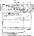
- Figure 2 shows a cross-sectional shape of a sintering layer and characteristics of exhaust gas in a sintering process according to an embodiment of the present disclosure.
- a combustion zone has a high temperature due to an active combustion of the to-be-sintered material.
- the combustion zone is gradually moved downward by the air sucked from an upper portion to a lower portion of the combustion zone, and the upper portion of the combustion zone is cooled by air at a room temperature.
- an air resistance of the combustion zone is larger than that of a non-sintered to-be-sintered material, an amount of the exhaust gas sucked into the wind-box 140 decreases as a thickness of the combustion zone increases.
- a transition point A between increase and decrease of a flow rate of the exhaust gas may be the point at which the air resistance inside the vehicle 110 increases (a point at which the thickness of the combustion zone increases).
- a high-temperature air passed through the combustion zone decreases in temperature as the hot air meets the non-sintered to-be-sintered material at the lower portion of the combustion zone. Vapor which is vapored in the combustion zone condenses to form a humid zone. When the combustion zone reaches the bottom of the vehicle 110, the humid zone and the non-sintered to-be-sintered material layer disappear. Thus, the hot air passed through the combustion zone is not cooled as the hot air passes through the non-sintered to-be-sintered material or the humid zone, and is sucked into the wind-box 140 at a high temperature. Accordingly, the temperature of the exhaust gas sucked into the wind-box 140 increases to a maximum temperature, and then the temperature decreases from a point where sintering of the to-be-sintered material is almost completed.
- wind-boxes 140 in this region may be connected to the circulation pipe 161 separately to provide a greater suction power than that of the other wind-boxes 140. That is, as the thickness of the combustion zone increases, the air resistance increases, but the suction power of the wind-box 140 may be increased to increase the airflow. Accordingly, the sintering of the to-be-sintered material proceeds smoothly, and the productivity and quality of the produced sintered ore may be improved.
- the transition point A between increase and decrease of a flow rate of the exhaust gas is the point where SO x is generated.
- SO x may react with moisture in the exhaust gas to generate sulfuric acid and may corrode the inside of the circulation pipe 161. Therefore, high temperature exhaust gas may be introduced into the circulation pipe 161 so that the temperature inside the circulation pipe 161 becomes higher than the acid dew point at which the sulfuric acid is generated. Accordingly, the circulation pipe 161 is connected to the wind-box 140 as far as the point where the temperature of the exhaust gas becomes maximum, therefore the internal temperature of the circulation pipe 161 may be raised up by the high temperature exhaust gas.
- the wind-boxes 140 from the transition point between increase and decrease of a flow rate of the exhaust gas to a point where a coal contained in the to-be-sintered material is exhausted, or to an inflection point of the exhaust gas temperature inclination may be connected to the circulation pipe 161.
- a flow rate sensor for measuring the flow rate of the exhaust gas and a temperature sensor for measuring the temperature of the exhaust gas may be installed in each wind-box 140. Therefore, it is possible to know the transition point between increase and decrease of a flow rate of the exhaust gas, and the point where the temperature of the exhaust gas becomes maximum among the plurality of the wind-boxes 140.
- the circulation line 162 forms the path along which the exhaust gas travels.
- the circulation line 162 may be connected at one end to the lower portion of the circulation pipe 161 and at the other end to the upper portion of the hood 150. Therefore, the exhaust gas sucked into the circulation pipe 161 may travel along the circulation line 162 and may be supplied to the hood 150.
- the blower 163 is disposed in the circulation line 162 and generates the suction power.
- the exhaust gas may be sucked in the wind-box 140 and the exhaust gas sucked in the wind-box 140 may be supplied to the hood 150 along the circulation line 162.
- the blower 163 provides the suction power to the wind-boxes 140 connected to the circulation pipe 161 among the plurality of the wind-boxes 140, and the main blower 53 provides the suction power to the wind-boxes 140 connected to the suction pipe 51.
- a greater suction power may be provided to each of the wind-boxes 140 than in a case when one blower provides suction power to all of the wind-boxes 140.
- the number of the wind-boxes 140 connected to the circulation pipe 161 may be lower than the number of the wind-boxes 140 connected to the suction pipe 51.
- the hood 150 is disposed above the vehicle 110 to supply the exhaust gas sucked into the circulation pipe 161 to the to-be-sintered material in the vehicle 110.
- the hood 150 may be extended in the anteroposterior direction, and top and side faces may be closed to cover the upper portion of the wind-boxes 140, and a bottom may be opened. Therefore, the exhaust gas supplied into the hood 150 may be discharged to the bottom of the hood 150.
- the hood 150 may be extended to cover upper portions of the wind-boxes 140 from a combustion start point of a bottom layer of the to-be-sintered material (or a point where the combustion zone reaches a lower portion of the vehicle 110) to a rear end-point of the traveling path.
- the exhaust gas is generated when the air passes along the to-be-sintered material, oxygen in the air combusts the to-be-sintered material. Therefore, the exhaust gas has a lower oxygen concentration than normal air. When such exhaust gas is supplied to the most active part of the combustion, the productivity and quality of the sintered ore are lowered.
- the exhaust gas may be circulated by supplying the exhaust gas to a region where the combustion is less frequent. That is, the hood 150 may be extended to supply the exhaust gas to the wind-boxes 140 between a point where the combustion starts to occur less (or the point where the combustion of the bottom layer of the to-be-sintered material begins) and a point where the combustion is completely completed (or the point where at the end of the traveling path).
- the number of the wind-boxes 140 covered by the hood 150 may be greater than the number of the wind-boxes 140 connected to the circulation pipe 161.
- the exhaust gas sucked into the circulation pipe 161 is bulky than the normal air because it is at a high temperature. Since a volume of the exhaust gas that the wind-box 140 may suck in is limited, when the number of the wind-boxes 140 covered by the hood 150 is small or the area where the hood 150 supplies the exhaust gas decreases, some of the exhaust gas discharged from the hood 150 may not be sucked into the wind-box 140 and may leak out and cause an environmental pollution.
- Lengthening a length of the hood 150 to increase the number of the wind-boxes 140 covered by the hood 150 allows all of the exhaust gas discharged from the hood 150 to be sucked into the wind-box 140, thus the exhaust gas discharged from the hood 150 may be blocked from flowing out to the outside. Therefore, the number of the wind-boxes 140 covered by the hood 150 may be increased more than the number of the wind-boxes 140 connected to the circulation pipe 161 so that the wind-box 140 may suck all of the exhaust gas discharged from the hood 150.
- a front end of the hood 150 and a rear end of the circulation pipe 161 may overlap with each other with respect to the anteroposterior direction.
- the air supply unit 170 may include a door unit 171 mounted on a top face of the hood 150.
- an opening may be defined in at least a portion of the top face of the hood 150, and the door unit 171 may be mounted on the top face of the hood 150 to open and close the opening.
- the air supplied from the air supply unit 170 may be normal air that does not pass through the to-be-sintered material, or external air.
- the opening of the hood 150 may be defined in a rectangular shape, and the door unit 171 may include a plate covering the opening and an actuator moving the plate.
- the plate may be defined corresponding to the shape of the opening and slidably mounted on the hood 150.
- the plate may be mounted on the top face of the hood 150 to be movable back and forth.
- the plate when the plate is moved forward, the plate may be positioned corresponding to the opening, and the opening may be closed.
- the opening may be opened as the plate moves. Therefore, when the opening of the hood 150 is opened, the external air may be introduced into the hood 150, and when the opening of the hood 150 is closed, the external air may be prevented from flowing into the inside of the hood 150.
- a structure and a shape of the plate and a method for mounting the plate on the hood 150 may not limited thereto and may vary.
- the actuator acts to move the plate.
- the actuator may be a cylinder, one end may be connected to the plate, and the other end may be fixedly mounted on the hood 150. Therefore, when the one end of the actuator moves forward, the plate moves forward to close the opening of the hood 150. When the one end of the actuator moves rearward, the plate moves rearward and the opening of the hood 150 may be opened.
- the way the actuator moves the plate may not limited thereto, but may vary.
- the opening is defined closer to the ignition-furnace 130 than the location where the circulation line 162 and the hood 150 are connected to each other. That is, the opening is defined in front of the portion where the circulation line 162 and the hood 150 are connected.
- the opening may be formed forwardly of (or at) a central point of the hood 150 in the anteroposterior direction thereof, while the circulation line 162 may be connected to a rearward point from the central point of the hood 150 in the anteroposterior direction thereof. Accordingly, the air may be introduced into a wind-box 140 located forwardly of the wind-boxes 140 covered by the hood 150, and circulated gas may be supplied to a wind-box 140 located rearwardly.
- the combustion is more actively performed in a vehicle 110 passing through the wind-box 140 located forwardly of the wind-boxes 140 covered by the hood 150 than a vehicle 110 passing through the wind-box 140 located rearwardly of the wind-boxes 140 covered by the hood 150. That is, more oxygen should be supplied to the vehicle 110 forwardly located in the anteroposterior direction thereof. Accordingly, the air may be supplied to the forwardly located vehicle 110 where the combustion is more active, and the exhaust gas having a small amount of the oxygen may be supplied to the rearwardly located vehicle 110.
- a pressure sensor 181 may be installed in the hood 150.
- the pressure sensor 181 serves to measure a pressure inside the hood 150.
- a single pressure sensor 181 may be provided to measure the pressure only at one position within the hood 150 or a plurality of the pressure sensor 181 may be provided to measure the pressure at a plurality of positions within the hood 150.
- the control unit 190 controls the operation of the door unit 171 based on the pressure inside the hood 150.
- the control unit 190 may include a transceiver 191 connected to the pressure sensor 181 to transmit and receive the pressure information inside the hood 150, a determiner 192 connected to the transceiver 191 to compare the pressure information inside the hood 150 received from the transceiver 191 with a preset pressure value, and a controller for controlling an operation of the actuator based on the determination of the determiner 192.
- the determiner 192 compares the pressure inside the hood 150 with the preset pressure value, and when the pressure inside the hood 150 is below the preset pressure, the determiner 192 transmits a signal to the controller to open the opening of the hood 150.
- the preset pressure value may be the atmospheric pressure. That is, in order for the air to flow into the hood 150, the pressure inside the hood 150 should be lower than the atmospheric pressure. Therefore, when opening the opening when the pressure inside the hood 150 is lower than the atmospheric pressure, the external air flows into the hood 150 through the opening by itself.
- the controller closes the opening of the hood 150. That is, when the pressure inside the hood 150 is higher than the atmospheric pressure, the gas inside the hood 150 may be discharged to the outside. Therefore, the exhaust gas inside the hood 150 may be discharged to the outside, which may pollute the environment. Therefore, when the pressure inside the hood 150 is higher than the external pressure, the opening of the hood 150 may be closed to prevent the exhaust gas in the hood 150 from flowing out.
- the preset pressure value is not limited thereto and may vary.
- Figure 3 shows a sintering apparatus according to another embodiment of the present disclosure.
- an air supply unit 170 forms an air moving path.
- the air supply unit 170 may include an air supply line 175 connected to the circulation line, a control valve 176 installed at the air supply line 175, and a cooler (not shown) disposed at the air supply line 175 to cool the air.
- the air supply line 175 is connected to the circulation line 162 at one end and the air may be injected at the other end. Thus, the air moving along the air supply line 175 may be supplied to the circulation line 162, mixed with the exhaust gas moving along the circulation line 162, and supplied to the hood 150.
- the control valve 176 serves to open and close the air moving path defined in the air supply line 175. Therefore, the air is supplied to the circulation line 162 when the control valve 176 is opened, and the air is not supplied to the circulation line 162 when the control valve 176 is closed.
- a cooler (not shown) is located between the control valve 176 and the other end of the air supply line 175 and cools the air moving along the air supply line 175. That is, the exhaust gas moving along the circulation line 162 is bulky because it is at a high temperature. Therefore, cooled air may be supplied to the circulation line 162 to lower a temperature of the high-temperature exhaust gas, thus the exhaust gas mixed with the air may be reduced in volume due to a decrease in temperature.
- the oxygen sensor 182 for measuring the oxygen concentration in the exhaust gas may be installed.
- the oxygen sensor 182 serves to measure the concentration of the oxygen passing along the circulation line 162.
- a control unit 190 may control an amount of the air supplied to the circulation line 162 based on the oxygen concentration inside the circulation line 162.
- the control unit 190 may include a transceiver 191 connected to the oxygen sensor 182 to transmit and receive the oxygen concentration information of the exhaust gas, a determiner 192 connected to the transceiver 191 to compare the oxygen concentration information received from the transceiver 191 with a preset oxygen concentration value, and a controller 193 for controlling an operation of the control valve 176 based on the determination of the determiner 192.
- the determiner 192 may compare the oxygen concentration in the exhaust gas with the preset oxygen concentration value, and when the oxygen concentration in the exhaust gas is below the preset oxygen concentration value, the determiner 192 transmits a signal to the controller 193 to open the control valve 176.
- the preset oxygen concentration value may be selected from among values between 13% to 16%. That is, the oxygen concentration in the exhaust gas is lower than that of the normal air. Therefore, the exhaust gas may lower a combustion efficiency of the to-be-sintered material compared to the normal air. Thus, when the oxygen concentration in the exhaust gas becomes too low, by supplying the air to the exhaust gas, the oxygen concentration may be increased.
- the preset oxygen concentration value may be not limited thereto and may vary.
- Figure 4 shows a sintering apparatus according to still another embodiment of the present disclosure.
- an air supply unit 170 may include all of the door unit 171 opening and closing the opening defined in the hood 150, the actuator moving the door unit 171, the air supply line 175 connected to the circulation line 162 to supply the air, and the control valve 176 opening and closing the air supply line 175.
- the pressure sensor 181 may be installed in the hood 150, and the oxygen sensor 182 may be installed in the circulation line 162 to measure the oxygen concentration in the exhaust gas.
- a control unit 190 may control the operation of the door unit 171 based on the pressure inside the hood 150, and may control the amount of the air supplied to the circulation line 162 based on the oxygen concentration in the circulation line 162.
- the control unit 190 may include a transceiver 191 connected to the pressure sensor 181 and the oxygen sensor 182 to transmit and receive the pressure information inside the hood 150 and the oxygen concentration information of the exhaust gas, a determiner 192 connected to the transceiver 191 to compare the pressure information inside the hood 150 and the oxygen concentration information of the exhaust gas respectively received from the transceiver 191 with the preset pressure value and the preset oxygen concentration value respectively, and a controller 193 for controlling the operation of at least one of the actuator and the control valve 176 based on the determination of the determiner 192.
- the determiner 192 may compare the pressure inside the hood 150 with the preset pressure, and when the pressure inside the hood 150 is below the preset pressure, the determiner 192 may transmit the signal to the controller 193 to open the opening of the hood 150. Conversely, when the pressure inside the hood 150 is higher than the preset pressure value, the controller 193 closes the opening of the hood 150.
- the determiner 192 may compare the oxygen concentration in the exhaust gas with the preset oxygen concentration value, and when the oxygen concentration in the exhaust gas is below the preset oxygen concentration value, the determiner 192 may transmit the signal to the controller 193 to open the control valve 176. In addition, when the oxygen concentration in the exhaust gas is below the preset oxygen concentration value, the opening of the hood 150 may be opened by controlling the operation of the actuator. Therefore, the air may be introduced into the hood 150 to increase the concentration of the oxygen supplied to the to-be-sintered material.
- Figure 5 shows a sintering method according to an embodiment of the present disclosure.
- the sintering method is a method for manufacturing a sintered ore, and includes a step S100 for loading the to-be-sintered material into the vehicle traveling along the traveling path, a step S200 igniting the flame on the top face of the to-be-sintered material, a step S300 for sucking the exhaust gas downwardly of the to-be-sintered material, and a step S400 for supplying a portion of the air and the sucked exhaust gas via the hood disposed above the traveling path to the to-be-sintered material in the vehicle.
- the to-be-sintered material is loaded into each vehicle 110 and form the to-be-sintered material layer.
- the flame is sprayed from the ignition-furnace 130 and ignited on the top face of the to-be-sintered material layer.
- the to-be-sintered material is sintered, and the sintered ore is produced.
- the sintered ore is supplied to the cooler (not shown) and cooled.
- the air (or the exhaust gas) sucked into a portion of the wind-boxes 140 may be supplied to the to-be-sintered material in the vehicle 110 traveling the traveling path.
- the exhaust gas in the wind-boxes 140 between the transition point between increase and decrease of a flow rate of the exhaust gas and the point where the temperature of the exhaust gas reaches the maximum may be circulated.
- the air resistance of the to-be-sintered material in the vehicle 110 passing between the transition point between increase and decrease of a flow rate of the exhaust gas and the point where the temperature of the exhaust gas reaches the maximum, is greater than the air resistance of the be-sintered material in the vehicle 110 passing the other region. In a region where the air resistance is large, the amount of the air passing through the to-be-sintered material decreases, so that the sintering may not process smoothly.
- the circulation pipe 161 When the circulation pipe 161 is connected to the wind-boxes 140 between the transition point between increase and decrease of a flow rate of the exhaust gas and the point where the temperature of the exhaust gas reaches the maximum, and when the blower 163 provides the suction power to the wind-boxes 140 connected to the circulation pipe 161, the wind-boxes 140 connected to the circulation pipe 161 may suck the air with higher suction power.
- the suction power supplied from the blower 163 also increases, so that the reduction of the amount of the air passing through the to-be-sintered material may be minimized.
- the sintering of the to-be-sintered material proceeds smoothly, and the quality of the sintered ore may be improved.
- the exhaust gas sucked into the circulation pipe 161 is supplied to the hood 150 disposed above the vehicle 110 along the circulation line 162.
- the hood 150 may be extended to cover upper portions of the wind-boxes 140 from the sintering start point of a bottom layer of the to-be-sintered material (or the combustion zone reaches the bottom of the vehicle 110) to a rear end-point of the traveling path. That is, since the oxygen concentration in the exhaust gas is lower than that of the normal air, the hood 150 may supply the exhaust gas to a region where the combustion occurs less or a region where the oxygen is less required.
- the wind-boxes 140 should be disposed in a number sufficient to suck the exhaust gas discharged from the hood 150.
- the wind-boxes 140 below the hood 150 do not sufficiently suck the air from the hood 150, air not sucked may be leaked to the outside and pollute the environment. Therefore, it is necessary to adjust the length of the hood 150 in the front and rear directions or the number of the wind-boxes 140 covered by the hood 150 in consideration of the amount of the air sucked into the circulation pipe 161.
- the external air may be supplied to the to-be-sintered material in the sintered vehicle 110 traveling the traveling path.
- the exhaust gas has a lower oxygen concentration than the normal air, so that the combustion efficiency of the to-be-sintered material may be reduced. Therefore, it is possible to improve the combustion efficiency of the to-be-sintered material by supplying air having an oxygen concentration higher than that of the exhaust gas together with the exhaust gas to the to-be-sintered material.
- the air may be supplied directly to the to-be-sintered material via the hood 150 or the air may be mixed with the exhaust gas and provided to the to-be-sintered material.
- the operation of the door unit 171 that opens and closes the opening of the hood 150 may be controlled.
- the pressure inside the hood 150 may be measured.
- the opening of the hood 150 may be opened.
- the preset pressure value may be the atmospheric pressure. That is, in order for the air to flow into the hood 150, the pressure inside the hood 150 should be lower than the atmospheric pressure. Accordingly, when the pressure inside the hood 150 is lower than the atmospheric pressure, opening the opening allows the outside air to flow into the hood 150 through the opening, and the air may be supplied to the to-be-sintered material.
- the opening of the hood 150 is closed. That is, when the pressure inside the hood 150 is higher than the atmospheric pressure, the gas inside the hood 150 may be discharged to the outside. Therefore, the exhaust gas inside the hood 150 may be discharged to the outside, which may pollute the environment. Therefore, when the pressure inside the hood 150 is higher than the external pressure, the opening of the hood 150 may be closed to prevent the exhaust gas in the hood 150 from flowing out.
- the air may be sprayed from the front end of the hood, and the exhaust gas may be sprayed from the rear end of the hood.
- air may be sprayed in a region forwardly of (or at) a central point of the hood 150 in the anteroposterior direction thereof, and the exhaust gas may be sprayed in a region rearwardly of (or at) a central point of the hood 150 in the anteroposterior direction thereof. That is, the opening may be formed forwardly of the central point of the hood 150 in the anteroposterior direction thereof, and the rearward point from the central point of the hood 150 in the anteroposterior direction thereof may be connected to the circulation line 162 and supplied the exhaust gas.
- the combustion is more actively performed in the vehicle 110 passing the wind-box 140 covered by the hood 150 and positioned forwardly of the central point of the hood 150 than the vehicle 110 passing the wind-box 140 covered by the hood 150 and positioned rearwardly of the central point of the hood 150. Accordingly, the combustion efficiency may be improved by supplying more oxygen to the front vehicle 110. Accordingly, the air may be supplied to the front vehicle 110 where the combustion is more active, and the exhaust gas having a small amount of the oxygen may be supplied to the rear vehicle 110.
- the oxygen concentration in the exhaust gas moving along the circulation line 162 may be measured. Then, the oxygen concentration in the exhaust gas may be compared with the preset concentration value, and when the oxygen concentration in the exhaust gas is below the preset concentration value, the control valve 176 may be opened.
- the preset concentration value may be selected from among values between 13% to 16%.
- the opening of the hood 150 may also be opened. Accordingly, the air may be introduced into the hood 150 to increase the concentration of the oxygen supplied to the to-be-sintered material.
- a point of time when the opening is opened is not limited to this and may be open at all times.
- the exhaust gas generated during the sintering process with the air may be supplied to the to-be-sintered material to be involved in the sintering process. Therefore, the exhaust gas may be circulated and reused, thereby suppressing or preventing the environmental pollution caused by the exhaust gas.
- the exhaust gas since the exhaust gas has a lower combustion efficiency than the normal air, the oxygen concentration may be deteriorated. Therefore, it is possible to suppress or prevent the deterioration of the combustion efficiency by supplying the exhaust gas together with the air having a high oxygen concentration to the to-be-sintered material. That is, the combustion efficiency of the to-be-sintered material may be improved by supplying the air, and the productivity of the sintering process may be increased.
- the air resistance increases and the amount of the air passing along the to-be-sintered material may decrease. Therefore, in the region where the air resistance increases, the air may be sucked with a greater suction power. Accordingly, the amount of the air passing through the to-be-sintered material is prevented from being reduced so that the combustion of the to-be-sintered material may be stably performed. Thus, the quality of the produced sintered ore may be improved.
Landscapes
- Engineering & Computer Science (AREA)
- Mechanical Engineering (AREA)
- General Engineering & Computer Science (AREA)
- Manufacture And Refinement Of Metals (AREA)
- Chemical & Material Sciences (AREA)
- Combustion & Propulsion (AREA)
Abstract
Description
- The present disclosure relates to a sintering apparatus and a sintering method, and more particularly to a sintering apparatus and a sintering method capable of improving a quality and a productivity of a sintered ore and reducing an emission of pollutants.
- A sintered ore used as a raw material for making iron in a blast furnace is manufactured by mixing an iron ore with a fine coke or an anthracite binder and then combusting the coke and sintering the iron ore with the combustion heat.
- A typical sintered ore manufacturing facility includes an upper ore hopper storing an upper ore therein, a surge hopper storing a mixed-raw material mixed with the iron ore, which is a raw material and the coke, which is a heat source therein, a plurality of vehicles arranged in a row, and provided with an upper ore and a mixed-raw material, and transferred in a process progressing direction, a conveyor configured for transferring the plurality of the vehicles in the process progressing direction, an ignition-furnace disposed above the vehicle transferred by the conveyor in the process progressing direction, and configured to firing a to-be-sintered material loaded on the vehicle, a plurality of a wind-boxes arranged on a transferring path in a row in the process progressing direction, and configured to suck an inside of the plurality of the vehicle, ducts connected to distal ends of the plurality of the wind-boxes, a blower (not shown) connected to the duct to generate a suction force.
- A sintering process is performed by applying a suction power to the vehicle by generating a negative pressure by the wind-box disposed below the vehicle.
- That is, when the blower is driven, the wind-box suck air at an upper portion of the vehicle, then an ignited flame on a top face of the to-be-sintered material is moved to a lower portion of the to-be-sintered material, therefore the sintering proceeds.
- Conventionally, sintered exhaust gas, which is air sucked through the wind-box, is discharged to the outside. However, these gases contain pollutants. In addition, the sintered exhaust gas has a lot of heat energy because it is generated by passing through a high temperature sintered ore. Therefore, when the sintered exhaust gas is discharged to the outside, it may cause an environmental pollution and a lot of energy may be lost.
- (Patent Document 1)
KR2014-0016658 A - The present disclosure provides a sintering apparatus and a sintering method capable of suppressing or preventing an environmental pollution by circulating an exhaust gas generated during a sintering process.
- The present disclosure provides a sintering apparatus and sintering method capable of improving a combustion efficiency and increasing a productivity by providing the exhaust gas and air to a to-be-sintered material.
- A sintering apparatus of the present disclosure includes: a vehicle disposed movably along a traveling path and having a to-be-sintered material loaded therein; an ignition-furnace disposed above the traveling path for spraying a flame to an upper portion of the to-be-sintered material; a plurality of wind-boxes disposed below the vehicle along the traveling path to provide a suction power to the vehicle; a hood disposed above the vehicle and extending along the traveling path; a circulation unit connected to some of a plurality of the wind-boxes and supplying exhaust gas sucked into said some of the wind-boxes to the hood; and an air supply unit connected to at least one of the hood and the circulation unit to supply air to the to-be-sintered material.
- The circulation unit includes: a circulation pipe connected to said some of the plurality of the wind-boxes and having an inner space for receiving the exhaust gas therein; a circulation line defining a path along which the exhaust gas moves, wherein one end of the circulation line is connected to the circulation pipe and the other end thereof is connected to the hood; and a blower disposed in the circulation line.
- The circulation pipe is connected to the wind-boxes between a transition point between increase and decrease of a flow rate of the exhaust gas, and a point where a temperature of the exhaust gas reaches a maximum.
- The hood is extended to cover upper portions of the wind-boxes from a sintering start point of a bottom layer of the to-be-sintered material to a rear end-point of the traveling path.
- A number of wind-boxes covered by the hood is greater than a number of wind-boxes connected to the circulation pipe.
- An opening is defined in a top portion of the hood, and the air supply unit includes a door unit mounted on the hood to open and close the opening.
- The opening is closer to the ignition-furnace than to a location where the circulation line and the hood are connected to each other.
- The sintering apparatus includes: a pressure sensor installed in the hood; and a control unit for controlling an operation of the door unit based on a pressure inside the hood.
- The air supply unit defines an air moving path and the air supply unit includes an air supply line connected to the circulation line.
- The sintering apparatus further includes: an oxygen sensor installed in the circulation line; and a control unit for controlling an amount of air to be supplied to the circulation line based on an oxygen concentration inside the circulation line.
- A method for producing a sintered ore of the present disclosure includes loading to-be-sintered material into a vehicle traveling along a traveling path; igniting a flame on a top face of the to-be-sintered material; sucking exhaust gas downwardly of the to-be-sintered material; and supplying a portion of air and the sucked exhaust gas via a hood disposed above the traveling path to the to-be-sintered material in the vehicle.
- Supplying the air to the to-be-sintered material includes: measuring a pressure inside the hood; and supplying the air to the to-be-sintered material when a pressure inside the hood is lower than a preset pressure value.
- Supplying the portion of the air and the sucked exhaust gas to the be-sintered material includes: spraying the air at a front end of the hood and spraying the exhaust gas at a rear end of the hood.
- Supplying the air to the to-be-sintered material includes: measuring an oxygen concentration in the exhaust gas; and supplying the air to the to-be-sintered material when the oxygen concentration in the sucked exhaust gas is lower than a preset oxygen concentration value.
- According to the embodiments of the present disclosure, the exhaust gas generated during the sintering process with air may be supplied to the to-be-sintered material and be involved in the sintering process. Therefore, the exhaust gas is circulated and reused, thereby suppressing or preventing the environmental pollution caused by the exhaust gas.
- In addition, since the oxygen concentration in the exhaust gas is lower than that of ordinary air, a combustion efficiency of the exhaust gas may be lowered. Therefore, since the exhaust gas and air having a high oxygen concentration are supplied to the to-be-sintered material together, a deterioration of the combustion efficiency may be suppressed or prevented. That is, by supplying the air, the combustion efficiency of the to-be-sintered material may be improved, and the productivity of the sintering process may be increased.
- In addition, as sintering of the to-be-sintered material proceeds, an air resistance may increase and the amount of air passing through the to-be-sintered material may be reduced. In a region where the air resistance increases, the air may be sucked into a larger suction power. Thus, by preventing the amount of the air passing through the to-be-sintered material from decreasing, the combustion of the to-be-sintered material may proceed stably. Thus, a quality of the produced sintered ore may be improved.
-
-
Figure 1 shows a sintering apparatus according to an embodiment of the present disclosure. -
Figure 2 shows a cross-sectional view of a sintering layer and characteristics of exhaust gas in a sintering process according to an embodiment of the present disclosure. -
Figure 3 shows a sintering apparatus according to another embodiment of the present disclosure. -
Figure 4 shows a sintering apparatus according to still another embodiment of the present disclosure. -
Figure 5 shows a sintering method according to an embodiment of the present disclosure. - Hereinafter, an embodiment of the present disclosure will now be described in detail with reference to the accompanying drawings. However, embodiments may be implemented in many different forms and should not be construed as limited to the embodiments set forth herein; rather, these embodiments are provided so that this disclosure will be thorough and complete, and will fully convey the scope of the embodiments to those skilled in the art. In the accompanying drawings, the dimensions of the structure show an enlarged scale than actual for clarity of the disclosure. The same or similar reference numerals are used throughout the drawings and the description in order to refer to the same or similar constituent elements.
-
Figure 1 shows a sintering apparatus according to an embodiment of the present disclosure. - Referring to
Figure 1 , asintering apparatus 100 according to an embodiment of the present disclosure includes avehicle 110 disposed movably along a traveling path and having a to-be-sintered material loaded therein, an ignition-furnace 130 disposed above the traveling path for spraying a flame to an upper portion of the to-be-sintered material, a plurality of wind-boxes 140 disposed below thevehicle 110 along the traveling path to provide a suction power to thevehicle 110, ahood 150 disposed above thevehicle 110 and extending along the traveling path, a circulation unit 160 connected to a portion of a plurality of the wind-boxes 140 and supplying exhaust gas sucked into a portion of the wind-boxes 140 to thehood 150, and anair supply unit 170 connected to at least one of thehood 150 and the circulation unit 160 to supply air to the to-be-sintered material. - Further, the
sintering apparatus 100 may include acharging unit 120 for charging the to-be-sintered material to thevehicle 110, a gasexhausting unit 50 connected to wind-boxes 140 not connected to the circulation unit 160 among the plurality of the wind-boxes 140, and acontrol unit 190 for controlling an operation of theair supply unit 170. In addition, thesintering apparatus 100 may include at least one of a pressure sensor 181 for measuring a pressure inside thehood 150 and anoxygen sensor 182 for measuring an oxygen concentration in the exhaust gas sucked into the circulation unit 160. - The
vehicle 110 is arranged to rotate in an endless track manner, and a closed loop is formed so that a traveling path on an upper side of the closed loop, a rotation path on a lower side of the closed loop, and a switching path connecting the traveling path and the rotation path may be formed. In the traveling path, the to-be-sintered material is loaded and sintered in thevehicle 110, and in the rotation path, anempty vehicle 110, in which the sintered ore is discharged, travels. - For example, the traveling path may be extended in an anteroposterior direction, and may include a charging section located at the foremost position in the traveling path and in which the
charging unit 120 is disposed, an ignition section located behind the charging section and in which the ignition-furnace is disposed, a sintering section located behind the charging section and in which the to-be-sintered material is sintered. That is, when thevehicle 110 is passing through the charging section, the to-be-sintered material is loaded into thevehicle 110, and when thevehicle 110 is passing through the ignition section, the flame is ignited to the to-be-sintered material in thevehicle 110. In the sintering section, the flame ignited to the to-be-sintered material is moved from an upper portion to a lower portion of the to-be-sintered material, therefore the sintered ore is produced. At this time, thevehicle 110 may travel from a front to a rear of the traveling path. - The
vehicle 110 forms a space in which the to-be-sintered material is contained therein, and the plurality of thevehicle 110 are disposed in the endless track to travel the traveling path and the rotation path. Accordingly, the plurality of thevehicles 110 may travel from the traveling path to the rotation path, or from the rotation path to the traveling path, thereby continuously producing the sintered ore. - The
charging unit 120 is disposed in the charging section of the traveling path. Thecharging unit 120 is disposed above thevehicle 110 so that the to-be-sintered material may be loaded into an open top of thevehicle 110. Thecharging unit 120 may include a hopper in which the to-be-sintered material is stored, and a charging chute disposed at a lower portion of theunit 120 and guiding the to-be-sintered material discharged from the hopper to the inside of thevehicle 110. Thus, the to-be-sintered material may be loaded into thevehicle 110 passing through the charging section. - The ignition-
furnace 130 is disposed in the ignition section of the traveling path. The ignition-furnace 130 is disposed behind the chargingunit 120 and disposed above thevehicle 110 to spray the flame into the to-be-sintered material loaded in thevehicle 110. Thus, the loaded material in thevehicle 110 passing through the ignition section may be ignited. - The plurality of the wind-
boxes 140 are disposed along the traveling path and disposed below thevehicles 110 passing along the traveling path to suck the exhaust gas. Thus, the air at the upper portion of thevehicle 110 may be sucked into the wind-box 140 through the to-be-sintered material in thevehicle 110. Accordingly, the flame ignited to a top face of the to-be-sintered material moves downward through the air, thereby sintering the entire to-be-sintered material. - The
gas exhausting unit 50 provides the suction power to the wind-boxes 140, which are not connected to the circulation unit 160 among the plurality of wind-boxes 140, and discharges sucked exhaust gas to the outside. Thegas exhausting unit 50 may include asuction pipe 51 connected to a lower portion of the wind-box 140 and having a space for receiving the exhaust gas sucked therein, adust collector 52 connected to thesuction pipe 51, amain blower 53, and astack 54. When themain blower 53 generates the suction power, the exhaust gas flowing into the wind-box 140 is sucked by thesuction pipe 51, filtered through thedust collector 52, and discharged to thestack 54. In this connection, the exhaust gas may be air sucked into the wind-box 140 passing through the to-be-sintered material. - The circulation unit 160 is connected to the portion of the plurality of wind-
boxes 140 and circulates the sucked exhaust gas to supply the exhaust gas to the upper portion of thevehicle 110. The circulation unit 160 includes acirculation pipe 161 connected to the portion of the plurality of the wind-boxes 140 and defining a space for receiving the exhaust gas therein, acirculation line 162 defining a path along which the exhaust gas moves, and one end of theline 162 connected to thecirculation pipe 161 and the other end connected to thehood 150, and ablower 163 disposed in thecirculation line 162. - The
circulation pipe 161 forms the space for receiving the exhaust gas therein, and is connected to the portion of the plurality of the wind-boxes 140. Specifically, thecirculation pipe 161 is connected to the wind-boxes 140 between a transition point between increase and decrease of a flow rate of the exhaust gas, and a point where a temperature of the exhaust gas reaches a maximum. -
Figure 2 shows a cross-sectional shape of a sintering layer and characteristics of exhaust gas in a sintering process according to an embodiment of the present disclosure. - A combustion zone has a high temperature due to an active combustion of the to-be-sintered material. Referring to
Figure 2 , the combustion zone is gradually moved downward by the air sucked from an upper portion to a lower portion of the combustion zone, and the upper portion of the combustion zone is cooled by air at a room temperature. In this connection, since an air resistance of the combustion zone is larger than that of a non-sintered to-be-sintered material, an amount of the exhaust gas sucked into the wind-box 140 decreases as a thickness of the combustion zone increases. Accordingly, a transition point A between increase and decrease of a flow rate of the exhaust gas may be the point at which the air resistance inside thevehicle 110 increases (a point at which the thickness of the combustion zone increases). - In this connection, a high-temperature air passed through the combustion zone decreases in temperature as the hot air meets the non-sintered to-be-sintered material at the lower portion of the combustion zone. Vapor which is vapored in the combustion zone condenses to form a humid zone. When the combustion zone reaches the bottom of the
vehicle 110, the humid zone and the non-sintered to-be-sintered material layer disappear. Thus, the hot air passed through the combustion zone is not cooled as the hot air passes through the non-sintered to-be-sintered material or the humid zone, and is sucked into the wind-box 140 at a high temperature. Accordingly, the temperature of the exhaust gas sucked into the wind-box 140 increases to a maximum temperature, and then the temperature decreases from a point where sintering of the to-be-sintered material is almost completed. - Because the air resistance increases at the wind-
boxes 140 between the transition point between increase and decrease of a flow rate of the exhaust gas, and a point where the temperature of the exhaust gas reaches a maximum temperature (BTP: Burn Through Point), in order to suck the air smoothly only wind-boxes 140 in this region may be connected to thecirculation pipe 161 separately to provide a greater suction power than that of the other wind-boxes 140. That is, as the thickness of the combustion zone increases, the air resistance increases, but the suction power of the wind-box 140 may be increased to increase the airflow. Accordingly, the sintering of the to-be-sintered material proceeds smoothly, and the productivity and quality of the produced sintered ore may be improved. - In addition, connecting the wind-
box 140 and thecirculation pipe 161 earlier the transition point A between increase and decrease of a flow rate of the exhaust gas, the combustion rate is accelerated but the air is cooled more rapidly. Therefore, a heat supplied to the sintering layer is insufficient, so that a strength of the sintered ore may be lowered. Therefore, the wind-box 140 and thecirculation pipe 161 must be connected at or after the transition point between increase and decrease of a flow rate of the exhaust gas. - In this connection, the transition point A between increase and decrease of a flow rate of the exhaust gas is the point where SOx is generated. SOx may react with moisture in the exhaust gas to generate sulfuric acid and may corrode the inside of the
circulation pipe 161. Therefore, high temperature exhaust gas may be introduced into thecirculation pipe 161 so that the temperature inside thecirculation pipe 161 becomes higher than the acid dew point at which the sulfuric acid is generated. Accordingly, thecirculation pipe 161 is connected to the wind-box 140 as far as the point where the temperature of the exhaust gas becomes maximum, therefore the internal temperature of thecirculation pipe 161 may be raised up by the high temperature exhaust gas. - Otherwise, the wind-
boxes 140 from the transition point between increase and decrease of a flow rate of the exhaust gas to a point where a coal contained in the to-be-sintered material is exhausted, or to an inflection point of the exhaust gas temperature inclination (BRP: Burn Rising Point) may be connected to thecirculation pipe 161. - In this connection, a flow rate sensor for measuring the flow rate of the exhaust gas and a temperature sensor for measuring the temperature of the exhaust gas may be installed in each wind-
box 140. Therefore, it is possible to know the transition point between increase and decrease of a flow rate of the exhaust gas, and the point where the temperature of the exhaust gas becomes maximum among the plurality of the wind-boxes 140. - The
circulation line 162 forms the path along which the exhaust gas travels. Thecirculation line 162 may be connected at one end to the lower portion of thecirculation pipe 161 and at the other end to the upper portion of thehood 150. Therefore, the exhaust gas sucked into thecirculation pipe 161 may travel along thecirculation line 162 and may be supplied to thehood 150. - The
blower 163 is disposed in thecirculation line 162 and generates the suction power. Thus, the exhaust gas may be sucked in the wind-box 140 and the exhaust gas sucked in the wind-box 140 may be supplied to thehood 150 along thecirculation line 162. - The
blower 163 provides the suction power to the wind-boxes 140 connected to thecirculation pipe 161 among the plurality of the wind-boxes 140, and themain blower 53 provides the suction power to the wind-boxes 140 connected to thesuction pipe 51. Thus, a greater suction power may be provided to each of the wind-boxes 140 than in a case when one blower provides suction power to all of the wind-boxes 140. In this connection, the number of the wind-boxes 140 connected to thecirculation pipe 161 may be lower than the number of the wind-boxes 140 connected to thesuction pipe 51. Therefore, even if theblower 163 and themain blower 53 generate the same suction power, a greater suction power may be generated in the wind-boxes 140 connected to thecirculation pipe 161. That is, by providing a greater suction power in regions where the air resistance is large, thereby suppressing or preventing a reduction of the flow rate of the exhaust gas. - The
hood 150 is disposed above thevehicle 110 to supply the exhaust gas sucked into thecirculation pipe 161 to the to-be-sintered material in thevehicle 110. Thehood 150 may be extended in the anteroposterior direction, and top and side faces may be closed to cover the upper portion of the wind-boxes 140, and a bottom may be opened. Therefore, the exhaust gas supplied into thehood 150 may be discharged to the bottom of thehood 150. - For example, the
hood 150 may be extended to cover upper portions of the wind-boxes 140 from a combustion start point of a bottom layer of the to-be-sintered material (or a point where the combustion zone reaches a lower portion of the vehicle 110) to a rear end-point of the traveling path. - The exhaust gas is generated when the air passes along the to-be-sintered material, oxygen in the air combusts the to-be-sintered material. Therefore, the exhaust gas has a lower oxygen concentration than normal air. When such exhaust gas is supplied to the most active part of the combustion, the productivity and quality of the sintered ore are lowered.
- Therefore, the exhaust gas may be circulated by supplying the exhaust gas to a region where the combustion is less frequent. That is, the
hood 150 may be extended to supply the exhaust gas to the wind-boxes 140 between a point where the combustion starts to occur less (or the point where the combustion of the bottom layer of the to-be-sintered material begins) and a point where the combustion is completely completed (or the point where at the end of the traveling path). - In addition, the number of the wind-
boxes 140 covered by thehood 150 may be greater than the number of the wind-boxes 140 connected to thecirculation pipe 161. The exhaust gas sucked into thecirculation pipe 161 is bulky than the normal air because it is at a high temperature. Since a volume of the exhaust gas that the wind-box 140 may suck in is limited, when the number of the wind-boxes 140 covered by thehood 150 is small or the area where thehood 150 supplies the exhaust gas decreases, some of the exhaust gas discharged from thehood 150 may not be sucked into the wind-box 140 and may leak out and cause an environmental pollution. - Lengthening a length of the
hood 150 to increase the number of the wind-boxes 140 covered by thehood 150 allows all of the exhaust gas discharged from thehood 150 to be sucked into the wind-box 140, thus the exhaust gas discharged from thehood 150 may be blocked from flowing out to the outside. Therefore, the number of the wind-boxes 140 covered by thehood 150 may be increased more than the number of the wind-boxes 140 connected to thecirculation pipe 161 so that the wind-box 140 may suck all of the exhaust gas discharged from thehood 150. In this connection, a front end of thehood 150 and a rear end of thecirculation pipe 161 may overlap with each other with respect to the anteroposterior direction. - The
air supply unit 170 according to an embodiment of the present disclosure may include adoor unit 171 mounted on a top face of thehood 150. In this connection, an opening may be defined in at least a portion of the top face of thehood 150, and thedoor unit 171 may be mounted on the top face of thehood 150 to open and close the opening. In addition, the air supplied from theair supply unit 170 may be normal air that does not pass through the to-be-sintered material, or external air. - For example, the opening of the
hood 150 may be defined in a rectangular shape, and thedoor unit 171 may include a plate covering the opening and an actuator moving the plate. - The plate may be defined corresponding to the shape of the opening and slidably mounted on the
hood 150. For example, the plate may be mounted on the top face of thehood 150 to be movable back and forth. Thus, when the plate is moved forward, the plate may be positioned corresponding to the opening, and the opening may be closed. Conversely, when the plate is moved rearward, the opening may be opened as the plate moves. Therefore, when the opening of thehood 150 is opened, the external air may be introduced into thehood 150, and when the opening of thehood 150 is closed, the external air may be prevented from flowing into the inside of thehood 150. However, a structure and a shape of the plate and a method for mounting the plate on thehood 150 may not limited thereto and may vary. - The actuator acts to move the plate. For example, the actuator may be a cylinder, one end may be connected to the plate, and the other end may be fixedly mounted on the
hood 150. Therefore, when the one end of the actuator moves forward, the plate moves forward to close the opening of thehood 150. When the one end of the actuator moves rearward, the plate moves rearward and the opening of thehood 150 may be opened. However, the way the actuator moves the plate may not limited thereto, but may vary. - In this connection, the opening is defined closer to the ignition-
furnace 130 than the location where thecirculation line 162 and thehood 150 are connected to each other. That is, the opening is defined in front of the portion where thecirculation line 162 and thehood 150 are connected. For example, the opening may be formed forwardly of (or at) a central point of thehood 150 in the anteroposterior direction thereof, while thecirculation line 162 may be connected to a rearward point from the central point of thehood 150 in the anteroposterior direction thereof. Accordingly, the air may be introduced into a wind-box 140 located forwardly of the wind-boxes 140 covered by thehood 150, and circulated gas may be supplied to a wind-box 140 located rearwardly. That is, the combustion is more actively performed in avehicle 110 passing through the wind-box 140 located forwardly of the wind-boxes 140 covered by thehood 150 than avehicle 110 passing through the wind-box 140 located rearwardly of the wind-boxes 140 covered by thehood 150. That is, more oxygen should be supplied to thevehicle 110 forwardly located in the anteroposterior direction thereof. Accordingly, the air may be supplied to the forwardly locatedvehicle 110 where the combustion is more active, and the exhaust gas having a small amount of the oxygen may be supplied to the rearwardly locatedvehicle 110. - In addition, a pressure sensor 181 may be installed in the
hood 150. The pressure sensor 181 serves to measure a pressure inside thehood 150. A single pressure sensor 181 may be provided to measure the pressure only at one position within thehood 150 or a plurality of the pressure sensor 181 may be provided to measure the pressure at a plurality of positions within thehood 150. - The
control unit 190 controls the operation of thedoor unit 171 based on the pressure inside thehood 150. Thecontrol unit 190 may include atransceiver 191 connected to the pressure sensor 181 to transmit and receive the pressure information inside thehood 150, adeterminer 192 connected to thetransceiver 191 to compare the pressure information inside thehood 150 received from thetransceiver 191 with a preset pressure value, and a controller for controlling an operation of the actuator based on the determination of thedeterminer 192. - The
determiner 192 compares the pressure inside thehood 150 with the preset pressure value, and when the pressure inside thehood 150 is below the preset pressure, thedeterminer 192 transmits a signal to the controller to open the opening of thehood 150. In this connection, the preset pressure value may be the atmospheric pressure. That is, in order for the air to flow into thehood 150, the pressure inside thehood 150 should be lower than the atmospheric pressure. Therefore, when opening the opening when the pressure inside thehood 150 is lower than the atmospheric pressure, the external air flows into thehood 150 through the opening by itself. - Conversely, when the pressure inside the
hood 150 is higher than the preset pressure value, the controller closes the opening of thehood 150. That is, when the pressure inside thehood 150 is higher than the atmospheric pressure, the gas inside thehood 150 may be discharged to the outside. Therefore, the exhaust gas inside thehood 150 may be discharged to the outside, which may pollute the environment. Therefore, when the pressure inside thehood 150 is higher than the external pressure, the opening of thehood 150 may be closed to prevent the exhaust gas in thehood 150 from flowing out. However, the preset pressure value is not limited thereto and may vary. -
Figure 3 shows a sintering apparatus according to another embodiment of the present disclosure. - Referring to
Figure 3 , anair supply unit 170 according to another embodiment of the present disclosure forms an air moving path. Theair supply unit 170 may include anair supply line 175 connected to the circulation line, acontrol valve 176 installed at theair supply line 175, and a cooler (not shown) disposed at theair supply line 175 to cool the air. - The
air supply line 175 is connected to thecirculation line 162 at one end and the air may be injected at the other end. Thus, the air moving along theair supply line 175 may be supplied to thecirculation line 162, mixed with the exhaust gas moving along thecirculation line 162, and supplied to thehood 150. - The
control valve 176 serves to open and close the air moving path defined in theair supply line 175. Therefore, the air is supplied to thecirculation line 162 when thecontrol valve 176 is opened, and the air is not supplied to thecirculation line 162 when thecontrol valve 176 is closed. - A cooler (not shown) is located between the
control valve 176 and the other end of theair supply line 175 and cools the air moving along theair supply line 175. That is, the exhaust gas moving along thecirculation line 162 is bulky because it is at a high temperature. Therefore, cooled air may be supplied to thecirculation line 162 to lower a temperature of the high-temperature exhaust gas, thus the exhaust gas mixed with the air may be reduced in volume due to a decrease in temperature. - In the
circulation line 162, theoxygen sensor 182 for measuring the oxygen concentration in the exhaust gas may be installed. Theoxygen sensor 182 serves to measure the concentration of the oxygen passing along thecirculation line 162. - In this connection, a
control unit 190 may control an amount of the air supplied to thecirculation line 162 based on the oxygen concentration inside thecirculation line 162. Thecontrol unit 190 may include atransceiver 191 connected to theoxygen sensor 182 to transmit and receive the oxygen concentration information of the exhaust gas, adeterminer 192 connected to thetransceiver 191 to compare the oxygen concentration information received from thetransceiver 191 with a preset oxygen concentration value, and acontroller 193 for controlling an operation of thecontrol valve 176 based on the determination of thedeterminer 192. - The
determiner 192 may compare the oxygen concentration in the exhaust gas with the preset oxygen concentration value, and when the oxygen concentration in the exhaust gas is below the preset oxygen concentration value, thedeterminer 192 transmits a signal to thecontroller 193 to open thecontrol valve 176. For example, the preset oxygen concentration value may be selected from among values between 13% to 16%. That is, the oxygen concentration in the exhaust gas is lower than that of the normal air. Therefore, the exhaust gas may lower a combustion efficiency of the to-be-sintered material compared to the normal air. Thus, when the oxygen concentration in the exhaust gas becomes too low, by supplying the air to the exhaust gas, the oxygen concentration may be increased. However, the preset oxygen concentration value may be not limited thereto and may vary. -
Figure 4 shows a sintering apparatus according to still another embodiment of the present disclosure. - Referring to
Figure 4 , anair supply unit 170 according to still another embodiment of the present disclosure may include all of thedoor unit 171 opening and closing the opening defined in thehood 150, the actuator moving thedoor unit 171, theair supply line 175 connected to thecirculation line 162 to supply the air, and thecontrol valve 176 opening and closing theair supply line 175. The pressure sensor 181 may be installed in thehood 150, and theoxygen sensor 182 may be installed in thecirculation line 162 to measure the oxygen concentration in the exhaust gas. - In this connection, a
control unit 190 may control the operation of thedoor unit 171 based on the pressure inside thehood 150, and may control the amount of the air supplied to thecirculation line 162 based on the oxygen concentration in thecirculation line 162. Thecontrol unit 190 may include atransceiver 191 connected to the pressure sensor 181 and theoxygen sensor 182 to transmit and receive the pressure information inside thehood 150 and the oxygen concentration information of the exhaust gas, adeterminer 192 connected to thetransceiver 191 to compare the pressure information inside thehood 150 and the oxygen concentration information of the exhaust gas respectively received from thetransceiver 191 with the preset pressure value and the preset oxygen concentration value respectively, and acontroller 193 for controlling the operation of at least one of the actuator and thecontrol valve 176 based on the determination of thedeterminer 192. - The
determiner 192 may compare the pressure inside thehood 150 with the preset pressure, and when the pressure inside thehood 150 is below the preset pressure, thedeterminer 192 may transmit the signal to thecontroller 193 to open the opening of thehood 150. Conversely, when the pressure inside thehood 150 is higher than the preset pressure value, thecontroller 193 closes the opening of thehood 150. - The
determiner 192 may compare the oxygen concentration in the exhaust gas with the preset oxygen concentration value, and when the oxygen concentration in the exhaust gas is below the preset oxygen concentration value, thedeterminer 192 may transmit the signal to thecontroller 193 to open thecontrol valve 176. In addition, when the oxygen concentration in the exhaust gas is below the preset oxygen concentration value, the opening of thehood 150 may be opened by controlling the operation of the actuator. Therefore, the air may be introduced into thehood 150 to increase the concentration of the oxygen supplied to the to-be-sintered material. -
Figure 5 shows a sintering method according to an embodiment of the present disclosure. - Referring to
Figure 5 , the sintering method according to an embodiment of the present disclosure is a method for manufacturing a sintered ore, and includes a step S100 for loading the to-be-sintered material into the vehicle traveling along the traveling path, a step S200 igniting the flame on the top face of the to-be-sintered material, a step S300 for sucking the exhaust gas downwardly of the to-be-sintered material, and a step S400 for supplying a portion of the air and the sucked exhaust gas via the hood disposed above the traveling path to the to-be-sintered material in the vehicle. - First, while the plurality of the
vehicles 110 sequentially pass below the chargingunit 120, the to-be-sintered material is loaded into eachvehicle 110 and form the to-be-sintered material layer. When the plurality of thevehicles 110 sequentially pass below the ignition-furnace 130, the flame is sprayed from the ignition-furnace 130 and ignited on the top face of the to-be-sintered material layer. When thevehicles 110 pass through the wind-box 140, while the flame is moved downward by the air sucked from the upper portion to the lower portion, the to-be-sintered material is sintered, and the sintered ore is produced. The sintered ore is supplied to the cooler (not shown) and cooled. - In this connection, the air (or the exhaust gas) sucked into a portion of the wind-
boxes 140 may be supplied to the to-be-sintered material in thevehicle 110 traveling the traveling path. In particular, the exhaust gas in the wind-boxes 140 between the transition point between increase and decrease of a flow rate of the exhaust gas and the point where the temperature of the exhaust gas reaches the maximum may be circulated. - The air resistance of the to-be-sintered material in the
vehicle 110 passing between the transition point between increase and decrease of a flow rate of the exhaust gas and the point where the temperature of the exhaust gas reaches the maximum, is greater than the air resistance of the be-sintered material in thevehicle 110 passing the other region. In a region where the air resistance is large, the amount of the air passing through the to-be-sintered material decreases, so that the sintering may not process smoothly. - When the
circulation pipe 161 is connected to the wind-boxes 140 between the transition point between increase and decrease of a flow rate of the exhaust gas and the point where the temperature of the exhaust gas reaches the maximum, and when theblower 163 provides the suction power to the wind-boxes 140 connected to thecirculation pipe 161, the wind-boxes 140 connected to thecirculation pipe 161 may suck the air with higher suction power. - Thus, even though the air resistance of the to-be-sintered material passing between the transition point between increase and decrease of a flow rate of the exhaust gas and the point where the temperature of the exhaust gas reaches the maximum is large, the suction power supplied from the
blower 163 also increases, so that the reduction of the amount of the air passing through the to-be-sintered material may be minimized. Thus, the sintering of the to-be-sintered material proceeds smoothly, and the quality of the sintered ore may be improved. - The exhaust gas sucked into the
circulation pipe 161 is supplied to thehood 150 disposed above thevehicle 110 along thecirculation line 162. Thehood 150 may be extended to cover upper portions of the wind-boxes 140 from the sintering start point of a bottom layer of the to-be-sintered material (or the combustion zone reaches the bottom of the vehicle 110) to a rear end-point of the traveling path. That is, since the oxygen concentration in the exhaust gas is lower than that of the normal air, thehood 150 may supply the exhaust gas to a region where the combustion occurs less or a region where the oxygen is less required. - Below the
hood 150, the wind-boxes 140 should be disposed in a number sufficient to suck the exhaust gas discharged from thehood 150. For example, when the wind-boxes 140 below thehood 150 do not sufficiently suck the air from thehood 150, air not sucked may be leaked to the outside and pollute the environment. Therefore, it is necessary to adjust the length of thehood 150 in the front and rear directions or the number of the wind-boxes 140 covered by thehood 150 in consideration of the amount of the air sucked into thecirculation pipe 161. - In addition, the external air may be supplied to the to-be-sintered material in the
sintered vehicle 110 traveling the traveling path. The exhaust gas has a lower oxygen concentration than the normal air, so that the combustion efficiency of the to-be-sintered material may be reduced. Therefore, it is possible to improve the combustion efficiency of the to-be-sintered material by supplying air having an oxygen concentration higher than that of the exhaust gas together with the exhaust gas to the to-be-sintered material. - The air may be supplied directly to the to-be-sintered material via the
hood 150 or the air may be mixed with the exhaust gas and provided to the to-be-sintered material. For example, the operation of thedoor unit 171 that opens and closes the opening of thehood 150 may be controlled. - First, the pressure inside the
hood 150 may be measured. When the internal pressure of thehood 150 is lower than the preset pressure value, the opening of thehood 150 may be opened. In this connection, the preset pressure value may be the atmospheric pressure. That is, in order for the air to flow into thehood 150, the pressure inside thehood 150 should be lower than the atmospheric pressure. Accordingly, when the pressure inside thehood 150 is lower than the atmospheric pressure, opening the opening allows the outside air to flow into thehood 150 through the opening, and the air may be supplied to the to-be-sintered material. - Conversely, when the pressure inside the
hood 150 is higher than the preset pressure value, the opening of thehood 150 is closed. That is, when the pressure inside thehood 150 is higher than the atmospheric pressure, the gas inside thehood 150 may be discharged to the outside. Therefore, the exhaust gas inside thehood 150 may be discharged to the outside, which may pollute the environment. Therefore, when the pressure inside thehood 150 is higher than the external pressure, the opening of thehood 150 may be closed to prevent the exhaust gas in thehood 150 from flowing out. - In this connection, the air may be sprayed from the front end of the hood, and the exhaust gas may be sprayed from the rear end of the hood. For example, air may be sprayed in a region forwardly of (or at) a central point of the
hood 150 in the anteroposterior direction thereof, and the exhaust gas may be sprayed in a region rearwardly of (or at) a central point of thehood 150 in the anteroposterior direction thereof. That is, the opening may be formed forwardly of the central point of thehood 150 in the anteroposterior direction thereof, and the rearward point from the central point of thehood 150 in the anteroposterior direction thereof may be connected to thecirculation line 162 and supplied the exhaust gas. - The combustion is more actively performed in the
vehicle 110 passing the wind-box 140 covered by thehood 150 and positioned forwardly of the central point of thehood 150 than thevehicle 110 passing the wind-box 140 covered by thehood 150 and positioned rearwardly of the central point of thehood 150. Accordingly, the combustion efficiency may be improved by supplying more oxygen to thefront vehicle 110. Accordingly, the air may be supplied to thefront vehicle 110 where the combustion is more active, and the exhaust gas having a small amount of the oxygen may be supplied to therear vehicle 110. - In this connection, the oxygen concentration in the exhaust gas moving along the
circulation line 162 may be measured. Then, the oxygen concentration in the exhaust gas may be compared with the preset concentration value, and when the oxygen concentration in the exhaust gas is below the preset concentration value, thecontrol valve 176 may be opened. For example, the preset concentration value may be selected from among values between 13% to 16%. Thus, when the oxygen concentration in the exhaust gas becomes too low, by supplying the air to the exhaust gas, the oxygen concentration may be increased. Therefore, a gas mixed with the exhaust gas and the air may be supplied to the to-be-sintered material. - Alternatively, when the oxygen concentration in the exhaust gas is below the preset concentration value, the opening of the
hood 150 may also be opened. Accordingly, the air may be introduced into thehood 150 to increase the concentration of the oxygen supplied to the to-be-sintered material. However, a point of time when the opening is opened is not limited to this and may be open at all times. - Thus, the exhaust gas generated during the sintering process with the air may be supplied to the to-be-sintered material to be involved in the sintering process. Therefore, the exhaust gas may be circulated and reused, thereby suppressing or preventing the environmental pollution caused by the exhaust gas.
- Further, since the exhaust gas has a lower combustion efficiency than the normal air, the oxygen concentration may be deteriorated. Therefore, it is possible to suppress or prevent the deterioration of the combustion efficiency by supplying the exhaust gas together with the air having a high oxygen concentration to the to-be-sintered material. That is, the combustion efficiency of the to-be-sintered material may be improved by supplying the air, and the productivity of the sintering process may be increased.
- In addition, as the sintering of the to-be-sintered material proceeds, the air resistance increases and the amount of the air passing along the to-be-sintered material may decrease. Therefore, in the region where the air resistance increases, the air may be sucked with a greater suction power. Accordingly, the amount of the air passing through the to-be-sintered material is prevented from being reduced so that the combustion of the to-be-sintered material may be stably performed. Thus, the quality of the produced sintered ore may be improved.
- Thus, in the detailed description of the present disclosure, the specific embodiments have been described. However, the embodiments may be implemented in many different forms and should not be construed as limited to the embodiments set forth herein. Thus, the scope of the present disclosure should be determined by the appended claims and their legal equivalents will be described below, rather than by the described embodiments.
Claims (14)
- A sintering apparatus comprising:a vehicle disposed movably along a traveling path and having a to-be-sintered material loaded therein;an ignition-furnace disposed above the traveling path for spraying a flame to an upper portion of the to-be-sintered material;a plurality of wind-boxes disposed below the vehicle along the traveling path to provide a suction power to the vehicle;a hood disposed above the vehicle and extending along the traveling path; a circulation unit connected to some of a plurality of the wind-boxes and supplying exhaust gas sucked into said some of the wind-boxes to the hood; andan air supply unit connected to at least one of the hood and the circulation unit to supply air to the to-be-sintered material.
- The sintering apparatus of claim 1, wherein the circulation unit includes:a circulation pipe connected to said some of the plurality of the wind-boxes and having an inner space for receiving the exhaust gas therein;a circulation line defining a path along which the exhaust gas moves, wherein one end of the circulation line is connected to the circulation pipe and the other end thereof is connected to the hood; anda blower disposed in the circulation line.
- The sintering apparatus of claim 2, wherein the circulation pipe is connected to the wind-boxes between a transition point between increase and decrease of a flow rate of the exhaust gas, and a point where a temperature of the exhaust gas reaches a maximum.
- The sintering apparatus of claim 2, wherein the hood is extended to cover upper portions of the wind-boxes from a sintering start point of a bottom layer of the to-be-sintered material to a rear end-point of the traveling path.
- The sintering apparatus of claim 2, wherein a number of wind-boxes covered by the hood is greater than a number of wind-boxes connected to the circulation pipe.
- The sintering apparatus of claim 2, wherein an opening is defined in a top portion of the hood,
wherein the air supply unit includes a door unit mounted on the hood to open and close the opening. - The sintering apparatus of claim 6, wherein the opening is closer to the ignition-furnace than to a location where the circulation line and the hood are connected to each other.
- The sintering apparatus of claim 6, wherein the sintering apparatus includes:a pressure sensor installed in the hood; anda control unit for controlling an operation of the door unit based on a pressure inside the hood.
- The sintering apparatus according to one of claims 2 to 8, wherein the air supply unit defines an air moving path,
wherein the air supply unit includes an air supply line connected to the circulation line. - The sintering apparatus of claim 9, wherein the sintering apparatus includes:an oxygen sensor installed in the circulation line; anda control unit for controlling an amount of air to be supplied to the circulation line based on an oxygen concentration inside the circulation line.
- A method for producing a sintered ore, the method comprising:loading to-be-sintered material into a vehicle traveling along a traveling path;igniting a flame onto a top face of the to-be-sintered material;sucking exhaust gas downwardly of the to-be-sintered material; andsupplying a portion of air and the sucked exhaust gas via a hood disposed above the traveling path to the to-be-sintered material in the vehicle.
- The method of claim 11, wherein supplying the air to the to-be-sintered material includes:measuring a pressure inside the hood; andsupplying the air to the to-be-sintered material when a pressure inside the hood is lower than a preset pressure value.
- The method of claim 12, wherein supplying the portion of the air and the sucked exhaust gas to the to-be-sintered material includes:spraying the air from a front end of the hood and spraying the exhaust gas from a rear end of the hood.
- The sintering method of claim 11, wherein supplying the air to the to-be-sintered material includes:measuring an oxygen concentration in the sucked exhaust gas; andsupplying the air to the to-be-sintered material when the oxygen concentration in the sucked exhaust gas is lower than a preset oxygen concentration value.
Applications Claiming Priority (2)
| Application Number | Priority Date | Filing Date | Title |
|---|---|---|---|
| KR1020160032765A KR101766672B1 (en) | 2016-03-18 | 2016-03-18 | Apparatus and Method for Manufacturing Sintered Ore |
| PCT/KR2016/013625 WO2017159962A1 (en) | 2016-03-18 | 2016-11-24 | Sintering apparatus and sintering method |
Publications (3)
| Publication Number | Publication Date |
|---|---|
| EP3431909A4 EP3431909A4 (en) | 2019-01-23 |
| EP3431909A1 true EP3431909A1 (en) | 2019-01-23 |
| EP3431909B1 EP3431909B1 (en) | 2020-06-03 |
Family
ID=59652587
Family Applications (1)
| Application Number | Title | Priority Date | Filing Date |
|---|---|---|---|
| EP16894692.9A Active EP3431909B1 (en) | 2016-03-18 | 2016-11-24 | Sintering apparatus and sintering method |
Country Status (5)
| Country | Link |
|---|---|
| EP (1) | EP3431909B1 (en) |
| JP (1) | JP6688396B2 (en) |
| KR (1) | KR101766672B1 (en) |
| CN (1) | CN108779960A (en) |
| WO (1) | WO2017159962A1 (en) |
Cited By (1)
| Publication number | Priority date | Publication date | Assignee | Title |
|---|---|---|---|---|
| CN112725615A (en) * | 2020-12-22 | 2021-04-30 | 中冶长天国际工程有限责任公司 | Soaking sintering method based on layered composite heat supply |
Families Citing this family (3)
| Publication number | Priority date | Publication date | Assignee | Title |
|---|---|---|---|---|
| CN110057197B (en) * | 2019-04-12 | 2020-05-08 | 诸暨市库仑环保科技有限公司 | A sintering flue gas waste heat circulation system |
| CN112985069B (en) * | 2021-04-09 | 2022-12-06 | 江西科技学院 | A multi-stage rotary atmosphere sintering furnace and its sintering process |
| CN114517259B (en) * | 2022-02-18 | 2024-10-18 | 广东韶钢松山股份有限公司 | Sintering machine and method for manufacturing sintered ore by using same |
Family Cites Families (15)
| Publication number | Priority date | Publication date | Assignee | Title |
|---|---|---|---|---|
| US2380056A (en) * | 1942-07-18 | 1945-07-10 | Dwight & Lloyd Sintering Compa | Heat-treating process and apparatus |
| US2410944A (en) * | 1943-05-13 | 1946-11-12 | American Smelting Refining | System for sintering |
| DE1136675B (en) * | 1961-03-28 | 1962-09-20 | Metallgesellschaft Ag | Method and device for performing endothermic processes on the sintering belt |
| JPS54130403A (en) * | 1978-03-31 | 1979-10-09 | Kawasaki Steel Corp | Manufacture of sintered iron ore |
| KR900010025Y1 (en) * | 1988-12-30 | 1990-10-29 | 주식회사 대륙제관 | Valve for gas bombe |
| JPH07331345A (en) * | 1994-06-03 | 1995-12-19 | Nippon Steel Corp | Raw material layer width direction uniform sintering method |
| JPH08291342A (en) * | 1995-04-18 | 1996-11-05 | Nippon Steel Corp | Exhaust gas circulation sintering method |
| JPH10219362A (en) * | 1997-02-06 | 1998-08-18 | Nippon Steel Corp | Sinter production method |
| KR100515042B1 (en) * | 2000-08-19 | 2005-09-15 | 주식회사 포스코 | Waste gas recirculation type iron ore sintering apparatus and the method by using LNG |
| KR100977792B1 (en) * | 2003-05-15 | 2010-08-24 | 주식회사 포스코 | Air flow control device of sintering machine |
| KR101300163B1 (en) * | 2011-11-17 | 2013-08-27 | 주식회사 포스코 | Circulating device of exhaust sintering gas in sintering plant and method for controlling the device |
| CN103375997B (en) * | 2012-04-28 | 2014-10-29 | 宝山钢铁股份有限公司 | Method for regulating and controlling circulating flue-gas temperature and oxygen content |
| CN102936651B (en) * | 2012-10-23 | 2015-10-07 | 鞍钢股份有限公司 | Sintering simultaneous desulfurization and denitrification system and desulfurization and denitrification method thereof |
| CN103499216B (en) * | 2013-09-26 | 2015-04-08 | 中南大学 | Iron mine sintering flue gas segmented circulation method |
| KR101461580B1 (en) * | 2013-12-23 | 2014-11-17 | 주식회사 포스코 | Apparatus for manufacturing sintered ore and method for manufacturing sintered ore using the same |
-
2016
- 2016-03-18 KR KR1020160032765A patent/KR101766672B1/en active Active
- 2016-11-24 JP JP2018539316A patent/JP6688396B2/en active Active
- 2016-11-24 CN CN201680083324.3A patent/CN108779960A/en active Pending
- 2016-11-24 WO PCT/KR2016/013625 patent/WO2017159962A1/en not_active Ceased
- 2016-11-24 EP EP16894692.9A patent/EP3431909B1/en active Active
Cited By (1)
| Publication number | Priority date | Publication date | Assignee | Title |
|---|---|---|---|---|
| CN112725615A (en) * | 2020-12-22 | 2021-04-30 | 中冶长天国际工程有限责任公司 | Soaking sintering method based on layered composite heat supply |
Also Published As
| Publication number | Publication date |
|---|---|
| EP3431909A4 (en) | 2019-01-23 |
| KR101766672B1 (en) | 2017-08-09 |
| EP3431909B1 (en) | 2020-06-03 |
| JP2019508658A (en) | 2019-03-28 |
| WO2017159962A1 (en) | 2017-09-21 |
| JP6688396B2 (en) | 2020-04-28 |
| CN108779960A (en) | 2018-11-09 |
Similar Documents
| Publication | Publication Date | Title |
|---|---|---|
| KR101665066B1 (en) | Apparatus and Method for Manufacturing Sintered Ore | |
| EP3431909B1 (en) | Sintering apparatus and sintering method | |
| EP3222953B1 (en) | Sintering apparatus and sintering method | |
| CN105849491B (en) | Manufacture the equipment and the method using the device fabrication sintering deposit of sintering deposit | |
| JP6005897B2 (en) | Method for producing sintered ore | |
| US8974571B2 (en) | Partially-reduced iron producing apparatus and partially-reduced iron producing method | |
| KR101719518B1 (en) | Apparatus and Method for Manufacturing Sintered Ore | |
| JP2001323326A (en) | Sintering machine operating method | |
| WO2009030809A1 (en) | Method and strand sintering equipment for continuous sintering and pre-reduction of pelletized mineral material | |
| CN110997953A (en) | Sintering equipment and sintering method using the same | |
| KR101300163B1 (en) | Circulating device of exhaust sintering gas in sintering plant and method for controlling the device | |
| KR20130060785A (en) | Burning temperature control apparatus and method using it | |
| MX2010006776A (en) | System and method for producing metallic iron. | |
| KR20170047503A (en) | Apparatus and Method for Manufacturing Sintered Ore | |
| EP3531052A1 (en) | Exhaust gas processing apparatus and processing method | |
| KR100977792B1 (en) | Air flow control device of sintering machine | |
| KR101818512B1 (en) | sintering apparatus and method for manufacturing sintered ore of using it | |
| KR20180047213A (en) | sintering apparatus and method for manufacturing sintered ore of using it | |
| KR100893270B1 (en) | Temperature controller of sinter ignition furnace | |
| KR101998754B1 (en) | Sintering apparatus | |
| KR100950399B1 (en) | Chiller for Sintered Ore Cooler | |
| CN222935357U (en) | Low-carbon emission reduction device for dry quenching | |
| KR101705055B1 (en) | Processing method for raw material | |
| KR101433531B1 (en) | Bi-directional ventilation apparatus | |
| JP2010126774A (en) | Method for manufacturing sintered ore |
Legal Events
| Date | Code | Title | Description |
|---|---|---|---|
| STAA | Information on the status of an ep patent application or granted ep patent |
Free format text: STATUS: THE INTERNATIONAL PUBLICATION HAS BEEN MADE |
|
| PUAI | Public reference made under article 153(3) epc to a published international application that has entered the european phase |
Free format text: ORIGINAL CODE: 0009012 |
|
| STAA | Information on the status of an ep patent application or granted ep patent |
Free format text: STATUS: REQUEST FOR EXAMINATION WAS MADE |
|
| 17P | Request for examination filed |
Effective date: 20180918 |
|
| A4 | Supplementary search report drawn up and despatched |
Effective date: 20190103 |
|
| AK | Designated contracting states |
Kind code of ref document: A1 Designated state(s): AL AT BE BG CH CY CZ DE DK EE ES FI FR GB GR HR HU IE IS IT LI LT LU LV MC MK MT NL NO PL PT RO RS SE SI SK SM TR |
|
| AX | Request for extension of the european patent |
Extension state: BA ME |
|
| DAV | Request for validation of the european patent (deleted) | ||
| DAX | Request for extension of the european patent (deleted) | ||
| GRAP | Despatch of communication of intention to grant a patent |
Free format text: ORIGINAL CODE: EPIDOSNIGR1 |
|
| STAA | Information on the status of an ep patent application or granted ep patent |
Free format text: STATUS: GRANT OF PATENT IS INTENDED |
|
| INTG | Intention to grant announced |
Effective date: 20191218 |
|
| GRAS | Grant fee paid |
Free format text: ORIGINAL CODE: EPIDOSNIGR3 |
|
| GRAA | (expected) grant |
Free format text: ORIGINAL CODE: 0009210 |
|
| STAA | Information on the status of an ep patent application or granted ep patent |
Free format text: STATUS: THE PATENT HAS BEEN GRANTED |
|
| AK | Designated contracting states |
Kind code of ref document: B1 Designated state(s): AL AT BE BG CH CY CZ DE DK EE ES FI FR GB GR HR HU IE IS IT LI LT LU LV MC MK MT NL NO PL PT RO RS SE SI SK SM TR |
|
| REG | Reference to a national code |
Ref country code: GB Ref legal event code: FG4D |
|
| REG | Reference to a national code |
Ref country code: CH Ref legal event code: EP Ref country code: AT Ref legal event code: REF Ref document number: 1277431 Country of ref document: AT Kind code of ref document: T Effective date: 20200615 |
|
| REG | Reference to a national code |
Ref country code: DE Ref legal event code: R096 Ref document number: 602016037743 Country of ref document: DE |
|
| REG | Reference to a national code |
Ref country code: NL Ref legal event code: FP |
|
| REG | Reference to a national code |
Ref country code: LT Ref legal event code: MG4D |
|
| PG25 | Lapsed in a contracting state [announced via postgrant information from national office to epo] |
Ref country code: GR Free format text: LAPSE BECAUSE OF FAILURE TO SUBMIT A TRANSLATION OF THE DESCRIPTION OR TO PAY THE FEE WITHIN THE PRESCRIBED TIME-LIMIT Effective date: 20200904 Ref country code: FI Free format text: LAPSE BECAUSE OF FAILURE TO SUBMIT A TRANSLATION OF THE DESCRIPTION OR TO PAY THE FEE WITHIN THE PRESCRIBED TIME-LIMIT Effective date: 20200603 Ref country code: NO Free format text: LAPSE BECAUSE OF FAILURE TO SUBMIT A TRANSLATION OF THE DESCRIPTION OR TO PAY THE FEE WITHIN THE PRESCRIBED TIME-LIMIT Effective date: 20200903 Ref country code: SE Free format text: LAPSE BECAUSE OF FAILURE TO SUBMIT A TRANSLATION OF THE DESCRIPTION OR TO PAY THE FEE WITHIN THE PRESCRIBED TIME-LIMIT Effective date: 20200603 Ref country code: LT Free format text: LAPSE BECAUSE OF FAILURE TO SUBMIT A TRANSLATION OF THE DESCRIPTION OR TO PAY THE FEE WITHIN THE PRESCRIBED TIME-LIMIT Effective date: 20200603 |
|
| PG25 | Lapsed in a contracting state [announced via postgrant information from national office to epo] |
Ref country code: BG Free format text: LAPSE BECAUSE OF FAILURE TO SUBMIT A TRANSLATION OF THE DESCRIPTION OR TO PAY THE FEE WITHIN THE PRESCRIBED TIME-LIMIT Effective date: 20200903 Ref country code: HR Free format text: LAPSE BECAUSE OF FAILURE TO SUBMIT A TRANSLATION OF THE DESCRIPTION OR TO PAY THE FEE WITHIN THE PRESCRIBED TIME-LIMIT Effective date: 20200603 Ref country code: RS Free format text: LAPSE BECAUSE OF FAILURE TO SUBMIT A TRANSLATION OF THE DESCRIPTION OR TO PAY THE FEE WITHIN THE PRESCRIBED TIME-LIMIT Effective date: 20200603 Ref country code: LV Free format text: LAPSE BECAUSE OF FAILURE TO SUBMIT A TRANSLATION OF THE DESCRIPTION OR TO PAY THE FEE WITHIN THE PRESCRIBED TIME-LIMIT Effective date: 20200603 |
|
| PG25 | Lapsed in a contracting state [announced via postgrant information from national office to epo] |
Ref country code: AL Free format text: LAPSE BECAUSE OF FAILURE TO SUBMIT A TRANSLATION OF THE DESCRIPTION OR TO PAY THE FEE WITHIN THE PRESCRIBED TIME-LIMIT Effective date: 20200603 |
|
| PG25 | Lapsed in a contracting state [announced via postgrant information from national office to epo] |
Ref country code: PT Free format text: LAPSE BECAUSE OF FAILURE TO SUBMIT A TRANSLATION OF THE DESCRIPTION OR TO PAY THE FEE WITHIN THE PRESCRIBED TIME-LIMIT Effective date: 20201006 Ref country code: IT Free format text: LAPSE BECAUSE OF FAILURE TO SUBMIT A TRANSLATION OF THE DESCRIPTION OR TO PAY THE FEE WITHIN THE PRESCRIBED TIME-LIMIT Effective date: 20200603 Ref country code: SM Free format text: LAPSE BECAUSE OF FAILURE TO SUBMIT A TRANSLATION OF THE DESCRIPTION OR TO PAY THE FEE WITHIN THE PRESCRIBED TIME-LIMIT Effective date: 20200603 Ref country code: EE Free format text: LAPSE BECAUSE OF FAILURE TO SUBMIT A TRANSLATION OF THE DESCRIPTION OR TO PAY THE FEE WITHIN THE PRESCRIBED TIME-LIMIT Effective date: 20200603 Ref country code: ES Free format text: LAPSE BECAUSE OF FAILURE TO SUBMIT A TRANSLATION OF THE DESCRIPTION OR TO PAY THE FEE WITHIN THE PRESCRIBED TIME-LIMIT Effective date: 20200603 Ref country code: RO Free format text: LAPSE BECAUSE OF FAILURE TO SUBMIT A TRANSLATION OF THE DESCRIPTION OR TO PAY THE FEE WITHIN THE PRESCRIBED TIME-LIMIT Effective date: 20200603 Ref country code: CZ Free format text: LAPSE BECAUSE OF FAILURE TO SUBMIT A TRANSLATION OF THE DESCRIPTION OR TO PAY THE FEE WITHIN THE PRESCRIBED TIME-LIMIT Effective date: 20200603 |
|
| PG25 | Lapsed in a contracting state [announced via postgrant information from national office to epo] |
Ref country code: PL Free format text: LAPSE BECAUSE OF FAILURE TO SUBMIT A TRANSLATION OF THE DESCRIPTION OR TO PAY THE FEE WITHIN THE PRESCRIBED TIME-LIMIT Effective date: 20200603 Ref country code: SK Free format text: LAPSE BECAUSE OF FAILURE TO SUBMIT A TRANSLATION OF THE DESCRIPTION OR TO PAY THE FEE WITHIN THE PRESCRIBED TIME-LIMIT Effective date: 20200603 Ref country code: IS Free format text: LAPSE BECAUSE OF FAILURE TO SUBMIT A TRANSLATION OF THE DESCRIPTION OR TO PAY THE FEE WITHIN THE PRESCRIBED TIME-LIMIT Effective date: 20201003 |
|
| REG | Reference to a national code |
Ref country code: DE Ref legal event code: R097 Ref document number: 602016037743 Country of ref document: DE |
|
| PLBE | No opposition filed within time limit |
Free format text: ORIGINAL CODE: 0009261 |
|
| STAA | Information on the status of an ep patent application or granted ep patent |
Free format text: STATUS: NO OPPOSITION FILED WITHIN TIME LIMIT |
|
| PG25 | Lapsed in a contracting state [announced via postgrant information from national office to epo] |
Ref country code: DK Free format text: LAPSE BECAUSE OF FAILURE TO SUBMIT A TRANSLATION OF THE DESCRIPTION OR TO PAY THE FEE WITHIN THE PRESCRIBED TIME-LIMIT Effective date: 20200603 |
|
| 26N | No opposition filed |
Effective date: 20210304 |
|
| PG25 | Lapsed in a contracting state [announced via postgrant information from national office to epo] |
Ref country code: SI Free format text: LAPSE BECAUSE OF FAILURE TO SUBMIT A TRANSLATION OF THE DESCRIPTION OR TO PAY THE FEE WITHIN THE PRESCRIBED TIME-LIMIT Effective date: 20200603 |
|
| PG25 | Lapsed in a contracting state [announced via postgrant information from national office to epo] |
Ref country code: MC Free format text: LAPSE BECAUSE OF FAILURE TO SUBMIT A TRANSLATION OF THE DESCRIPTION OR TO PAY THE FEE WITHIN THE PRESCRIBED TIME-LIMIT Effective date: 20200603 |
|
| REG | Reference to a national code |
Ref country code: CH Ref legal event code: PL |
|
| GBPC | Gb: european patent ceased through non-payment of renewal fee |
Effective date: 20201124 |
|
| PG25 | Lapsed in a contracting state [announced via postgrant information from national office to epo] |
Ref country code: LU Free format text: LAPSE BECAUSE OF NON-PAYMENT OF DUE FEES Effective date: 20201124 |
|
| REG | Reference to a national code |
Ref country code: BE Ref legal event code: MM Effective date: 20201130 |
|
| PG25 | Lapsed in a contracting state [announced via postgrant information from national office to epo] |
Ref country code: CH Free format text: LAPSE BECAUSE OF NON-PAYMENT OF DUE FEES Effective date: 20201130 Ref country code: LI Free format text: LAPSE BECAUSE OF NON-PAYMENT OF DUE FEES Effective date: 20201130 |
|
| PG25 | Lapsed in a contracting state [announced via postgrant information from national office to epo] |
Ref country code: IE Free format text: LAPSE BECAUSE OF NON-PAYMENT OF DUE FEES Effective date: 20201124 Ref country code: FR Free format text: LAPSE BECAUSE OF NON-PAYMENT OF DUE FEES Effective date: 20201130 |
|
| PG25 | Lapsed in a contracting state [announced via postgrant information from national office to epo] |
Ref country code: GB Free format text: LAPSE BECAUSE OF NON-PAYMENT OF DUE FEES Effective date: 20201124 |
|
| PG25 | Lapsed in a contracting state [announced via postgrant information from national office to epo] |
Ref country code: IS Free format text: LAPSE BECAUSE OF FAILURE TO SUBMIT A TRANSLATION OF THE DESCRIPTION OR TO PAY THE FEE WITHIN THE PRESCRIBED TIME-LIMIT Effective date: 20201003 Ref country code: MT Free format text: LAPSE BECAUSE OF FAILURE TO SUBMIT A TRANSLATION OF THE DESCRIPTION OR TO PAY THE FEE WITHIN THE PRESCRIBED TIME-LIMIT Effective date: 20200603 Ref country code: CY Free format text: LAPSE BECAUSE OF FAILURE TO SUBMIT A TRANSLATION OF THE DESCRIPTION OR TO PAY THE FEE WITHIN THE PRESCRIBED TIME-LIMIT Effective date: 20200603 |
|
| PG25 | Lapsed in a contracting state [announced via postgrant information from national office to epo] |
Ref country code: MK Free format text: LAPSE BECAUSE OF FAILURE TO SUBMIT A TRANSLATION OF THE DESCRIPTION OR TO PAY THE FEE WITHIN THE PRESCRIBED TIME-LIMIT Effective date: 20200603 |
|
| REG | Reference to a national code |
Ref country code: AT Ref legal event code: UEP Ref document number: 1277431 Country of ref document: AT Kind code of ref document: T Effective date: 20200603 |
|
| PG25 | Lapsed in a contracting state [announced via postgrant information from national office to epo] |
Ref country code: BE Free format text: LAPSE BECAUSE OF NON-PAYMENT OF DUE FEES Effective date: 20201130 |
|
| REG | Reference to a national code |
Ref country code: DE Ref legal event code: R081 Ref document number: 602016037743 Country of ref document: DE Owner name: POSCO CO., LTD, POHANG-SI, KR Free format text: FORMER OWNER: POSCO, POHANG-SI, GYEONGSANGBUK-DO, KR Ref country code: DE Ref legal event code: R081 Ref document number: 602016037743 Country of ref document: DE Owner name: POSCO CO., LTD, POHANG- SI, KR Free format text: FORMER OWNER: POSCO, POHANG-SI, GYEONGSANGBUK-DO, KR Ref country code: DE Ref legal event code: R081 Ref document number: 602016037743 Country of ref document: DE Owner name: POSCO HOLDINGS INC., KR Free format text: FORMER OWNER: POSCO, POHANG-SI, GYEONGSANGBUK-DO, KR |
|
| REG | Reference to a national code |
Ref country code: NL Ref legal event code: PD Owner name: POSCO HOLDINGS INC.; KR Free format text: DETAILS ASSIGNMENT: CHANGE OF OWNER(S), CHANGE OF LEGAL ENTITY; FORMER OWNER NAME: POSCO Effective date: 20221026 |
|
| REG | Reference to a national code |
Ref country code: NL Ref legal event code: PD Owner name: POSCO CO., LTD; KO Free format text: DETAILS ASSIGNMENT: CHANGE OF OWNER(S), ASSIGNMENT; FORMER OWNER NAME: POSCO Effective date: 20221109 |
|
| REG | Reference to a national code |
Ref country code: AT Ref legal event code: PC Ref document number: 1277431 Country of ref document: AT Kind code of ref document: T Owner name: POSCO CO., LTD, KR Effective date: 20230228 |
|
| REG | Reference to a national code |
Ref country code: DE Ref legal event code: R081 Ref document number: 602016037743 Country of ref document: DE Owner name: POSCO CO., LTD, POHANG-SI, KR Free format text: FORMER OWNER: POSCO HOLDINGS INC., SEOUL, KR Ref country code: DE Ref legal event code: R081 Ref document number: 602016037743 Country of ref document: DE Owner name: POSCO CO., LTD, POHANG- SI, KR Free format text: FORMER OWNER: POSCO HOLDINGS INC., SEOUL, KR |
|
| PGFP | Annual fee paid to national office [announced via postgrant information from national office to epo] |
Ref country code: NL Payment date: 20251105 Year of fee payment: 10 |
|
| PGFP | Annual fee paid to national office [announced via postgrant information from national office to epo] |
Ref country code: DE Payment date: 20251105 Year of fee payment: 10 |
|
| PGFP | Annual fee paid to national office [announced via postgrant information from national office to epo] |
Ref country code: AT Payment date: 20251105 Year of fee payment: 10 |
|
| PGFP | Annual fee paid to national office [announced via postgrant information from national office to epo] |
Ref country code: TR Payment date: 20251103 Year of fee payment: 10 |