EP3431882A1 - Cleaning system and cooking device - Google Patents
Cleaning system and cooking device Download PDFInfo
- Publication number
- EP3431882A1 EP3431882A1 EP17182157.2A EP17182157A EP3431882A1 EP 3431882 A1 EP3431882 A1 EP 3431882A1 EP 17182157 A EP17182157 A EP 17182157A EP 3431882 A1 EP3431882 A1 EP 3431882A1
- Authority
- EP
- European Patent Office
- Prior art keywords
- water
- glass surface
- cleaning system
- input port
- hot water
- Prior art date
- Legal status (The legal status is an assumption and is not a legal conclusion. Google has not performed a legal analysis and makes no representation as to the accuracy of the status listed.)
- Withdrawn
Links
- 238000004140 cleaning Methods 0.000 title claims abstract description 123
- 238000010411 cooking Methods 0.000 title claims abstract description 45
- XLYOFNOQVPJJNP-UHFFFAOYSA-N water Substances O XLYOFNOQVPJJNP-UHFFFAOYSA-N 0.000 claims abstract description 388
- 239000011521 glass Substances 0.000 claims abstract description 121
- 239000006185 dispersion Substances 0.000 claims abstract description 40
- 238000010408 sweeping Methods 0.000 claims description 48
- 238000010438 heat treatment Methods 0.000 claims description 26
- 239000007921 spray Substances 0.000 claims description 21
- 230000006698 induction Effects 0.000 claims description 16
- 230000005672 electromagnetic field Effects 0.000 claims description 2
- 239000002699 waste material Substances 0.000 description 43
- 238000010586 diagram Methods 0.000 description 10
- 238000000034 method Methods 0.000 description 10
- 230000003287 optical effect Effects 0.000 description 5
- 239000002241 glass-ceramic Substances 0.000 description 3
- 230000008646 thermal stress Effects 0.000 description 3
- 241000169624 Casearia sylvestris Species 0.000 description 2
- 230000003213 activating effect Effects 0.000 description 2
- 239000003302 ferromagnetic material Substances 0.000 description 2
- 238000009434 installation Methods 0.000 description 2
- 239000000463 material Substances 0.000 description 2
- 230000006978 adaptation Effects 0.000 description 1
- 230000005574 cross-species transmission Effects 0.000 description 1
- 230000005294 ferromagnetic effect Effects 0.000 description 1
- 239000002184 metal Substances 0.000 description 1
- 238000005086 pumping Methods 0.000 description 1
- 230000007704 transition Effects 0.000 description 1
Images


Classifications
-
- F—MECHANICAL ENGINEERING; LIGHTING; HEATING; WEAPONS; BLASTING
- F24—HEATING; RANGES; VENTILATING
- F24C—DOMESTIC STOVES OR RANGES ; DETAILS OF DOMESTIC STOVES OR RANGES, OF GENERAL APPLICATION
- F24C15/00—Details
- F24C15/10—Tops, e.g. hot plates; Rings
-
- B—PERFORMING OPERATIONS; TRANSPORTING
- B08—CLEANING
- B08B—CLEANING IN GENERAL; PREVENTION OF FOULING IN GENERAL
- B08B3/00—Cleaning by methods involving the use or presence of liquid or steam
- B08B3/02—Cleaning by the force of jets or sprays
-
- B—PERFORMING OPERATIONS; TRANSPORTING
- B08—CLEANING
- B08B—CLEANING IN GENERAL; PREVENTION OF FOULING IN GENERAL
- B08B7/00—Cleaning by methods not provided for in a single other subclass or a single group in this subclass
- B08B7/0064—Cleaning by methods not provided for in a single other subclass or a single group in this subclass by temperature changes
-
- F—MECHANICAL ENGINEERING; LIGHTING; HEATING; WEAPONS; BLASTING
- F24—HEATING; RANGES; VENTILATING
- F24C—DOMESTIC STOVES OR RANGES ; DETAILS OF DOMESTIC STOVES OR RANGES, OF GENERAL APPLICATION
- F24C13/00—Stoves or ranges with additional provisions for heating water
-
- F—MECHANICAL ENGINEERING; LIGHTING; HEATING; WEAPONS; BLASTING
- F24—HEATING; RANGES; VENTILATING
- F24C—DOMESTIC STOVES OR RANGES ; DETAILS OF DOMESTIC STOVES OR RANGES, OF GENERAL APPLICATION
- F24C14/00—Stoves or ranges having self-cleaning provisions, e.g. continuous catalytic cleaning or electrostatic cleaning
- F24C14/005—Stoves or ranges having self-cleaning provisions, e.g. continuous catalytic cleaning or electrostatic cleaning using a cleaning liquid
Definitions
- the invention relates to a cleaning system for cleaning a cooker glass surface of a cooking device. Further the present invention relates to a respective cooking device.
- the present invention will mainly be described in conjunction with cookers, especially induction cookers, and cleaning the glass surface of such cookers.
- Modern cooking devices usually comprise a glass surface, e.g. a glass-ceramic cooktop panel, on which the cooking vessels are placed for heating and cooking. Such cooking devices are electrically operated and do not require any gas. Further, no metal vessel holder or other equipment is provided on the glass surface that could hold the cooking vessels. Instead such cooking devices comprise a smooth glass or glass ceramic surface. This design with the smooth glass surface for cooking devices provides for very simple handling of the cooking device by the users. For example, there is no balance problem with the cooking vessels, because of the smooth glass surface there is no open fire.
- Users may for example use blades to scratch off the solidified waste from the glass surface.
- this may be cumbersome and erroneous use of the blade may leave marks on the glass surface.
- the present invention provides a cleaning system with the features of claim 1 and a cooking device with the features of claim 14.
- the present invention is based on the finding that manual mechanical cleaning of glass surfaces of cooking devices is a cumbersome task and that automatic cleaning arrangements that mechanically remove residual waste from the glass surface are very complex.
- the present invention therefore provides a cleaning system for glass surfaces of cooking devices that makes use of the thermal expansion that such residual waste will undergo, when exposed to different temperatures.
- the movement caused by such thermal expansion will crack the solidified residual waste and the waste may be easily removed.
- the thermal expansion of the glass or glass-ceramic surface in contrast will be very small or almost not present. Therefore in addition to the internal thermal stress in the solidified waste, a relative movement or force between the glass surface and the solidified waste will be present that supports loosening of the solidified waste.
- the present invention therefore provides the cleaning system with a cold water input port and a hot water input port.
- the water dispersion device may then e.g. flood the glass surface with cold water.
- the cold water will usually be cooler than the surrounding temperature. Therefore, the solidified waste will also cool down to the temperature of the cold water.
- the water dispersion device may flood the glass surface with hot water.
- the hot water may e.g. be received via a hot water supply of a house installation. Such water may have temperatures of about 50 °C or more. If the cold water has a temperature of about 10 °C or 15 °C a temperature difference of 35 °C to 40 °C may be achieved without any further heating elements.
- the water dispersion device may alternatingly flood the glass surface with cold water and hot water. Therefore, if the first temperature gradient is not sufficient to crack all solidified waste open, further iterations may be performed until the solidified waste is removed or at least loosened.
- a user may e.g. observe the cleaning system and stop the cleaning of the glass surface when he sees that the solidified waste is removed or loosened to his satisfaction.
- the present invention provides a cleaning system that requires minimal mechanical treatment of the solidified waste.
- the cleaning system may therefore comprise a very simply yet effective arrangement. Further the burden of manually cleaning the glass surface of a cooking device is taken from the user.
- the cleaning system may e.g. be integrated into a cooking device. It is however understood, that the cleaning system may also be portable or may be a kind of frame that may be releasably attached to the glass surface of the cooking device.
- the cleaning system may comprise a water heating device that may be fluidly coupled to the hot water input port and configured to heat up water.
- Providing the cleaning system with a dedicated heating device allows heating up water if e.g. no hot water is available.
- the water may be heated up to temperatures that are higher than the temperatures that are provided e.g. by the water system in a building.
- the water heating device may e.g. be an electrical water heating device.
- the cleaning system may e.g. comprise an electric kettle or a flow heater.
- the water heating device may e.g. be arranged between the cold water input port and the hot water input port and heat up the water received via the cold water input port.
- the cleaning system may further be operated without a dedicated pump, with the pressure that is present in the building water installation. If an electric kettle or any other type of water tank with heater coil is used, it may be necessary to provide an additional pump for pumping the hot water out of the water tank.
- the cleaning system may comprise a water tank that may be connected to the cold water input port and the hot water input port and may be configured to provide water to the cold water input port and the hot water input port.
- a water tank may store the water that is required to perform the cleaning of the glass surface.
- the cleaning system may therefore be operated autonomously without a connection to a building water system.
- a water tank may be filled with distilled or filtered water that comprises a reduced amount of e.g. limescale or scale. This will reduce the deposits in the cleaning system and therefore increase the operational live time of the cleaning system.
- the water heating device may e.g. be fluidly coupled between the water tank and the hot water input port.
- the cold water input port and the hot water input port may be provided as a single water port and the water heating device may be arranged in the water tank.
- the water tank may therefore supply a single water port either with cold water or hot water.
- the water tank may e.g. comprise cold water in the beginning of the cleaning process and supply that cold water to the water dispersion device. Then the water heating device may heat up remaining water in the water tank and provide hot water to the water dispersion device.
- the water dispersion device or another device may collect the cold water and transfer that water back to the water tank or a temporary buffer. After dispersing the hot water, the collected cold water may be provided to the water tank to cool down the water tank. Alternatively, the cold water may be provided to the water dispersion device via a bypass, without entering the hot water tank. A further cleaning cycle may then immediately be initiated.
- the water tank may in addition comprise a connection to a water network or system to supply cold water to the water tank after heating up, e.g. to perform a second cleaning cycle.
- the cold water may be bypassed around the hot water tank and may be directly provided to the water dispersion device.
- the cleaning system may also comprise a water outlet to disperse water after a sweep.
- the water tank may be provided below an induction coil of the cooking device and comprise a heating element that may be configured to heat up by an electromagnetic field generated by the induction coil.
- the cleaning system may be integrated in an induction cooking device.
- an induction coil that is used to heat up cooking vessels that are used to cook on the induction cooking device may also be used to heat up water in the water tank.
- the heating element may be a simple ferromagnetic plate or the like and may be integrated in the water tank. No further or dedicated water heating device is therefore necessary.
- the cleaning system may comprise a cold water pump fluidly arranged between the cold water input port and the water dispersion device. Further, the cleaning system may comprise a hot water pump fluidly arranged between the hot water input port and the water dispersion device and may comprise a controller configured to control the cold water pump and the hot water pump.
- the controller may be any type of control device, e.g. a processor or microcontroller that is electronically coupled to the cold water pump and the hot water pump and may drive the water pumps as required.
- the controller may e.g. perform the overall control of the cleaning process and timely control the water pumps accordingly.
- the controller may comprise the power drivers for the pumps and provide power signals to the water pumps.
- the pumps may comprise the power drivers and the controller may provide logic level signals to the pumps.
- the cold water pump may also be implemented as a controllable valve if the cold water inlet is connected to a water supply system that provides a high enough pressure.
- the controller may e.g. start a cleaning cycle by activating the cold water pump.
- the controller may e.g. comprise a preprogrammed cleaning cycle flow that defines for how long the cold water pump is activated to supply enough water to the water dispersion device.
- the controller may stop the cold water pump and wait for a predetermined amount of time, e.g. 0 to 30 seconds. This delay serves for the solidified waste to cool down to the temperature of the water.
- the controller may activate the hot water pump to disperse hot water over the glass surface. Again a delay, e.g. 0 to 30 seconds, may be introduced for the hot water to transfer heat to the solidified waste. After the delay a new cleaning cycle may be initiated.
- the cold water pump and the hot water pump may be the same water pump, especially for a water tank with water heating device that is connected to a single water input port.
- the controller may also be connected to the water heating device, if present in the cleaning system, and control the water heating device accordingly when required.
- the water dispersion device may comprise a number, i.e. one or more, of water spray nozzles configured to disperse the cold water and the hot water over the glass surface.
- the water spray nozzles may e.g. be arranged on an edge of the glass surface and may be oriented to the glass surface. Water dispersion may therefore be provided from one side of the glass surface. It is however understood, that water dispersion may also be provided by water spray nozzles on different sides of the glass surface.
- the water spray nozzles may e.g. be coupled to the cold water pump and the hot water pump to receive the cold water and the hot water.
- the cleaning system may comprise a number of water collection orifices for collecting water from the glass surface.
- the water collection orifices may be provided as openings at an edge of the glass surface. If the water spray nozzles are provided at an edge of the glass surface, the water collection orifices may be on an edge opposite to the edge that comprises the water spray nozzles.
- the water collection orifices may be coupled to a pipe system that guides the water e.g. into a water outlet of the cleaning system or the water tank. Further, pumps or the like that are necessary to pump the water may also be provided in the pipe system.
- the cleaning system may comprise a movable sweeping bar configured to controllably sweep over the glass surface.
- the movable sweeping bar may e.g. comprise a rubber lip or the like that serves to sweep water off the glass surface.
- the movable sweeping bar may be arranged on a rail or any other type of guide and may e.g. be hand driven by a user or motor driven, e.g. under control of the above mentioned controller.
- the movable sweeping bar may cover the glass surface from one side to the other and may move parallel to an edge of the glass surface. Therefore, a movement of the movable sweeping bar from one edge to the opposite edge will sweep the entire glass surface.
- the movable sweeping bar may be arranged movable between an edge of the glass surface that accommodates the water spray nozzles and an opposite edge of the glass surface that accommodates the water collection orifices.
- the movable sweeping bar may retract behind the water spray nozzles on the respective edge of the glass surface to let the water flow onto the glass surface from the water spray nozzles.
- the movable sweeping bar may move from the edge that accommodates the water spray nozzles to the edge that accommodates the water collection orifices to sweep the water into the water collection orifices.
- the movable sweeping bar may be manually operated.
- the movable sweeping bar may also be electrically actuated, e.g. by a motor drive.
- the motor drive may e.g. comprise a threaded spindle with a respective spindle nut or ball screw nut.
- control of the motor may e.g. be performed by the above mentioned controller that may control the movable sweeping bar when required and as required after dispersing cold or hot water.
- the movable sweeping bar may comprise the water spray nozzles and/or the water collection orifices.
- the movable sweeping bar moves over the complete area of the glass surface and may therefore advantageously be used to extend the cold and hot water over the complete glass surface. At the same time the movable sweeping bar may also be used to collect the water from the glass surface.
- the movable sweeping bar may e.g. comprise openings that act as the water collection orifices, e.g. similar to suction nozzles. It is understood, that a respective aspirator or suction blower may be fluidly coupled to such openings.
- the movable sweeping bar may comprise cold water spray nozzles on one side of the bar and hot water spray nozzles on the other side of the bar.
- the water collection orifices may be positioned in the center of the movable sweeping bar on the downside, i.e. towards the glass surface. This allows e.g. dispersing cold water in a first sweep of the movable sweeping bar.
- the cold water may be removed by the water collection orifices and hot water may be sprayed onto the glass surface on the other side of the movable sweeping bar with the same sweep. Efficient cleaning of the glass surface is therefore possible.
- the cleaning system may comprise a surface scanner for scanning the glass surface for dirt and providing a feedback signal.
- the surface scanner serves for identifying residual waste or solidified waste on the glass surface.
- the feedback signal may then e.g. be used to determine the amount of waste on the glass surface. If after a cleaning cycle any waste remains on the glass surface, another cleaning cycle may be initiated.
- the surface scanner may e.g. comprise an optical scanner like e.g. a camera or the like.
- Object or image recognition algorithms may be implemented in a controller to identify waste in the camera images and determine the feedback signals.
- a camera may e.g. be arranged on an edge of the glass surface or over the glass surface.
- the camera may also be arranged e.g. on the movable sweeping bar.
- the optical scanner may e.g. comprise a scanner bar, like e.g. used in document scanners.
- the surface scanner may be provided or accommodated on the movable sweeping bar and comprise a resistor bar.
- the resistor bar may e.g. change its resistance depending on a pressure on the bar.
- the resistor bar may move over the glass surface with a predetermined pressure onto the glass surface. Residual waste on the glass surface will automatically provide an elevation over the glass surface. Therefore, any residual waste on the glass surface, i.e. the elevation provided by that waste, will increase the pressure on the resistor bar and will therefore increase the resistance of the resistor bar. This increase in resistance may be measured to determine the feedback value or may be used as the feedback value.
- the cleaning system may comprise a cleaning controller that may be configured to determine the number of cleaning cycles that are necessary to clean the glass surface based on the feedback signal.
- the cleaning controller may be any type of controller that is capable of evaluating the feedback signal from the surface scanner.
- the feedback controller may e.g. be arranged inside the above mentioned controller that may provide the central control unit of the cleaning system. Based on the detected amount of waste on the glass surface, the controller may then determine the number of cleaning cycles.
- the feedback value may be determined for every sweep or cleaning cycle and the cleaning controller may decide after every sweep or cleaning cycle whether another cleaning cycle is necessary or not.
- the cooking device may comprise a number, i.e. one or more, of induction coils under the glass surface to form cooking hobs.
- the cleaning system may be used with any type of cooking device that comprises a glass surface.
- the cleaning system may be beneficially used with induction cooking devices, where one of the induction coils may be used to heat up water in the water tank.
- Fig. 1 shows a block diagram of a cleaning system 100.
- the cleaning system 100 comprises a cold water input port 101 that receives cold water 102, e.g. from a building water supply system.
- the cleaning system 100 further comprises a hot water input port 103 for receiving hot water 104.
- the cleaning system 100 comprises a water dispersion device 105 that is coupled to the cold water input port 101 and the hot water input port 103.
- the water dispersion device 105 alternatingly disperses the cold water 102 and the hot water 104 over the glass surface 150 of the cooking device 151.
- the glass surface 150 may e.g. be a ceramic-glass surface and the cooking device 151 may e.g. be an induction cooking device 151.
- the cleaning system 100 serves to crack open that solidified waste by alternatingly dispersing the cold water 102 and hot water 104 over the glass surface 150.
- "Alternatingly” in this context may refer to the water dispersion device 105 dispersing cold water 102 until the solidified waste adopts the temperature of the cold water 102 and then dispersing hot water 104 until the solidified waste adopts the temperature of the temperature of the hot water 104. This pattern will serve to induce thermal stress in the solidified waste and finally crack open or loosen the solidified waste.
- a building water system may provide hot water 104 of about 50 °C - 70 °C. This temperature may be high enough for proper cleaning of the glass surface 150. However, should higher temperatures be needed or should the building water system deliver hot water 104 of lower temperatures, it is understood, that the cleaning system 100 may comprise water heating device that is fluidly coupled between the water supply, e.g. the building water system or the cold water input port 101, and the hot water input port 103. The water heating device may then heat up water prior to dispersing the water on the glass surface 150.
- the water heating device may e.g. comprise a water tank that is connected to the cold water input port 101 for receiving cold water 102.
- the water tank may on the other end be fluidly connected to the water dispersion device 105.
- the water tank may therefore directly provide cold water 102 to the water dispersion device 105 or heat up the cold water and then provide hot water 104 to the water dispersion device 105.
- controllable valves may be provided for controlling the flow of cold water 102 and hot water 104 in the cleaning system 100. Further, a controller may be provided that controls the valves accordingly.
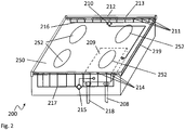
- Fig. 2 shows a block diagram of a cleaning system 200.
- the cleaning system 200 is arranged on or around a glass surface 250.
- the glass surface 250 is the ceramic-glass surface of an induction cooker with four induction hobs 252.
- the cleaning system 200 comprises a single water port 208, that unifies the cold water input port and the hot water input port. Attached to the single water port 208 is a water tank 209.
- the water tank 209 also provides a water heating device. This double function is achieved e.g. by provided the water tank 209 with a ferromagnetic material under one of the induction hobs 252. Activating the respective hob 252 will automatically heat up that ferromagnetic material and therefore heat up the water in the water tank 209.
- the water tank 209 is coupled on an outlet to a water pump 210.
- the water pump 210 is a single water pump 210 for cold water and hot water that may be provided by the water tank 209.
- the water pump 210 is coupled via pipes 216 to water spray nozzles 211 (for sake of clarity only three are provided with reference signs) that are provided on a movable sweeping bar 212.
- a rail 219 is provided alongside an edge of the glass surface 250 that is orthogonal to the movable sweeping bar 212.
- the movable sweeping bar 212 may be movable along the rail 219 to sweep the entire glass surface 250. It is understood, that as alternative or in addition to the pipes 216 there may also be flexible tubes provided to supply the water spray nozzles 211 with hot or cold water.
- the movable sweeping bar 212 further comprises a surface scanner 213.
- water collection orifices 214 are provided on the edge of the glass surface 250 that is opposite to the edge that accommodates the movable sweeping bar 212 in an idle position.
- the water collection orifices 214 are coupled to a water collector pump 215 via pipes.
- the water collector pump 215 pumps the water from the water collection orifices 214 to the water tank 209.
- the water pump 210 is further fluidly coupled to a water drain.
- controller or control unit that controls the cleaning system 200 or the cleaning process performed with the cleaning system 200.
- the movable sweeping bar 212 may e.g. move over the glass surface 250 for the surface scanner 213 to scan the glass surface 250 for waste and for determining the amount of cleaning cycles necessary to clean the waste of the glass surface 250.
- the surface scanner 213 may e.g. be an optical scanner or a pressure-sensitive resistive scanner.
- a controller may e.g. evaluate a feedback signal from the surface scanner 213 and determine the necessary amount of cleaning cycles.
- the controller may also control the further elements of the cleaning system 200 and in addition any valves that may be necessary to control the water flow in the glass surface 250.
- the movable sweeping bar 212 may then rest in the idle position until the waste adopts the temperature of the cold water. Meanwhile, the water tank 209 may heat up water.
- the movable sweeping bar 212 may then sweep the glass surface 250 to provide the cold water to the water collection orifices 214, where the cold water is collected and pumped into the tank 209 by water collector pump 215, where it may be heated up.
- the heated hot water may then be provided to the movable sweeping bar 212.
- the movable sweeping bar 212 may e.g. disperse the hot water on the way back into the idle position. After reaching the idle position, the movable sweeping bar 212 may again rest until the waste adopts the temperature of the hot water.
- This cleaning cycle may be repeated until the surface scanner 213 detects no more waste during a scan or e.g. until a predetermined maximum number of cleaning cycles is performed.
- the above described scheme may work with any type of movable sweeping bar 212, especially with a movable sweeping bar 212 that comprises water spray nozzles 211 on only one side.
- the cleaning cycles may be accelerated with a movable sweeping bar 212 as shown in Fig. 4 (see corresponding explanations below).
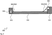
- Fig. 3 shows a block diagram of another cleaning system 300.
- the cleaning system 300 comprises a carrier structure 325 on opposite edges of the glass surface 350.
- the carrier structure 325 carries on one side the water dispersion device 305 and comprises on the opposite side drain pipes 326.
- the water dispersion device 305 disperses hot water 302 or cold water 304 over the glass surface 350.
- the water dispersion device 305 may e.g. disperse the hot water 302 or cold water 304 with a force sufficient to disperse the hot water 302 or cold water 304 to the drain pipes 326.
- After flooding the glass surface 350 with cold water 302 the water dispersion device 305 may flood the glass surface 350 with hot water 304 until all cold water is drained into the drain pipes 326. After the last cycle a manual cleanup may be necessary.
- the advantage of this embodiment is that no moving parts are necessary. After the last dispersion of hot water 304, cold water may be dispersed to avoid danger of scalding
- an optical surface scanner like e.g. a camera may be provided that may analyze the complete glass surface 250 without moving over the glass surface 350.
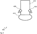
- Fig. 4 shows block diagram of a water dispersion device 405.
- the water dispersion device 405 comprises a movable sweeping bar 412.
- the movable sweeping bar 412 carries on the bottom a surface scanner 413.
- the surface scanner 413 is provided as a resistor bar that changes its resistance with changing pressure on the bar. It is understood however, that e.g. an optical scanner bar could also be used.
- the water dispersion device 405 comprises on the left side of the movable sweeping bar 412 cold water nozzles 430 and on the right side of the movable sweeping bar 412 hot water nozzles 431. This means that in the water dispersion device 405 different nozzles 430, 431 are provided for hot and cold water. It is understood, that although not explicitly shown, any type of pipes or tubes may be provided that are necessary to connect the cold water nozzles 430 and the hot water nozzles 431 to the water supply.
- the cleaning cycles with the cleaning system may be accelerated because while cold water is swept into the water collection orifices (see Fig. 2 ) hot water may already be dispersed on the other side of the water dispersion device 405 and vice versa.
- the water collection orifices may be provided on two opposite edges of the glass surface to collect either cold or hot water.
- Fig. 5 shows a flow diagram of a possible embodiment of a method for operating an embodiment of a cleaning system 100, 200, 300 according to the present invention.
- step S1 the surface scanner 213, 413 is moved over the glass surface 150, 250, 350.
- step S2 the surface scanner 213, 413 scans the glass surface 150, 250, 350 for solidified waste. This means that the steps S1 and S2 may be executed substantially in parallel. If the surface scanner 213, 413 detects waste on the glass surface 150, 250, 350, in step S3 the amount of waste that is detected is counted and a number of cleaning cycles that are necessary to clean the glass surface 150, 250, 350 may be determined. If the number of cleaning cycles is greater than zero decision D1 initiates a cleaning cycle and branches to step S4 that comprises dispersing cold water 102, 302 on the glass surface 150, 250, 350.
- step S5 hot water 104, 304 is dispersed on the glass surface.
- the transition from cold water 102, 302 to hot water 104, 304 induces thermal stress in the waste and cracks the waste open.
- Step S6 the counter for the necessary cleaning cycles is reduced by one and the method returns to decision D1.
- the present invention provides a cleaning system 100, 200, 300 for cleaning a cooker glass surface 150, 250, 350 of a cooking device 151, the cleaning system 100, 200, 300 comprising a cold water input port 101 for receiving cold water 102, 302, a hot water input port 103 for receiving hot water 104, 304, and a water dispersion device 105, 305, 405 that is coupled to the cold water input port 101 and the hot water input port 103 and is configured to alternatingly disperse cold water 102, 302 and hot water 104, 304 over the glass surface 150, 250, 350. Further, the present invention provides a cooking device.
Landscapes
- Engineering & Computer Science (AREA)
- Chemical & Material Sciences (AREA)
- Combustion & Propulsion (AREA)
- Mechanical Engineering (AREA)
- General Engineering & Computer Science (AREA)
- Chemical Kinetics & Catalysis (AREA)
- Cleaning By Liquid Or Steam (AREA)
Abstract
Description
- The invention relates to a cleaning system for cleaning a cooker glass surface of a cooking device. Further the present invention relates to a respective cooking device.
- Although applicable to any surface that has to be cleaned, the present invention will mainly be described in conjunction with cookers, especially induction cookers, and cleaning the glass surface of such cookers.
- Modern cooking devices usually comprise a glass surface, e.g. a glass-ceramic cooktop panel, on which the cooking vessels are placed for heating and cooking. Such cooking devices are electrically operated and do not require any gas. Further, no metal vessel holder or other equipment is provided on the glass surface that could hold the cooking vessels. Instead such cooking devices comprise a smooth glass or glass ceramic surface. This design with the smooth glass surface for cooking devices provides for very simple handling of the cooking device by the users. For example, there is no balance problem with the cooking vessels, because of the smooth glass surface there is no open fire.
- During use of such cooking devices, content of the cooking vessels or other material may spill over the glass surface. Due to the high temperatures of the glass surface during cooking, the spilled material may solidify and bake on the smooth glass surface. Such solidified waste will adhere to the glass surface and may be difficult to clean up.
- Users may for example use blades to scratch off the solidified waste from the glass surface. However, this may be cumbersome and erroneous use of the blade may leave marks on the glass surface.
- Accordingly, there is a need for a simple method for cleaning glass surfaces of cooking devices.
- The present invention provides a cleaning system with the features of
claim 1 and a cooking device with the features of claim 14. - Accordingly, it is provided:
- A cleaning system for cleaning a cooker glass surface of a cooking device, the cleaning system comprising a cold water input port for receiving cold water, a hot water input port for receiving hot water, and a water dispersion device that is coupled to the cold water input port and the hot water input port and is configured to alternatingly disperse cold water and hot water over the glass surface.
- Further, it is provided:
- A cooking device comprising a glass surface, and a cleaning system according to any one of the preceding claims.
- The present invention is based on the finding that manual mechanical cleaning of glass surfaces of cooking devices is a cumbersome task and that automatic cleaning arrangements that mechanically remove residual waste from the glass surface are very complex.
- The present invention therefore provides a cleaning system for glass surfaces of cooking devices that makes use of the thermal expansion that such residual waste will undergo, when exposed to different temperatures. The movement caused by such thermal expansion will crack the solidified residual waste and the waste may be easily removed. The thermal expansion of the glass or glass-ceramic surface in contrast will be very small or almost not present. Therefore in addition to the internal thermal stress in the solidified waste, a relative movement or force between the glass surface and the solidified waste will be present that supports loosening of the solidified waste.
- The present invention therefore provides the cleaning system with a cold water input port and a hot water input port. The water dispersion device may then e.g. flood the glass surface with cold water. The cold water will usually be cooler than the surrounding temperature. Therefore, the solidified waste will also cool down to the temperature of the cold water. After flooding the glass surface with the cold water the water dispersion device may flood the glass surface with hot water. The hot water may e.g. be received via a hot water supply of a house installation. Such water may have temperatures of about 50 °C or more. If the cold water has a temperature of about 10 °C or 15 °C a temperature difference of 35 °C to 40 °C may be achieved without any further heating elements.
- As stated above, the water dispersion device may alternatingly flood the glass surface with cold water and hot water. Therefore, if the first temperature gradient is not sufficient to crack all solidified waste open, further iterations may be performed until the solidified waste is removed or at least loosened.
- A user may e.g. observe the cleaning system and stop the cleaning of the glass surface when he sees that the solidified waste is removed or loosened to his satisfaction.
- By taking advantage of the thermal expansion of the solidified waste, the present invention provides a cleaning system that requires minimal mechanical treatment of the solidified waste. The cleaning system may therefore comprise a very simply yet effective arrangement. Further the burden of manually cleaning the glass surface of a cooking device is taken from the user.
- The cleaning system may e.g. be integrated into a cooking device. It is however understood, that the cleaning system may also be portable or may be a kind of frame that may be releasably attached to the glass surface of the cooking device.
- Further embodiments of the present invention are subject of the further subclaims and of the following description, referring to the drawings.
- In an embodiment, the cleaning system may comprise a water heating device that may be fluidly coupled to the hot water input port and configured to heat up water.
- Providing the cleaning system with a dedicated heating device allows heating up water if e.g. no hot water is available. In addition, the water may be heated up to temperatures that are higher than the temperatures that are provided e.g. by the water system in a building. The water heating device may e.g. be an electrical water heating device. The cleaning system may e.g. comprise an electric kettle or a flow heater.
- The water heating device may e.g. be arranged between the cold water input port and the hot water input port and heat up the water received via the cold water input port.
- In a further embodiment with a flow heater the cleaning system may further be operated without a dedicated pump, with the pressure that is present in the building water installation. If an electric kettle or any other type of water tank with heater coil is used, it may be necessary to provide an additional pump for pumping the hot water out of the water tank.
- In an embodiment, the cleaning system may comprise a water tank that may be connected to the cold water input port and the hot water input port and may be configured to provide water to the cold water input port and the hot water input port.
- A water tank may store the water that is required to perform the cleaning of the glass surface. The cleaning system may therefore be operated autonomously without a connection to a building water system. Further, a water tank may be filled with distilled or filtered water that comprises a reduced amount of e.g. limescale or scale. This will reduce the deposits in the cleaning system and therefore increase the operational live time of the cleaning system. The water heating device may e.g. be fluidly coupled between the water tank and the hot water input port.
- In another embodiment, the cold water input port and the hot water input port may be provided as a single water port and the water heating device may be arranged in the water tank.
- The water tank may therefore supply a single water port either with cold water or hot water. The water tank may e.g. comprise cold water in the beginning of the cleaning process and supply that cold water to the water dispersion device. Then the water heating device may heat up remaining water in the water tank and provide hot water to the water dispersion device.
- Prior to dispersing the hot water onto the glass surface, the water dispersion device or another device may collect the cold water and transfer that water back to the water tank or a temporary buffer. After dispersing the hot water, the collected cold water may be provided to the water tank to cool down the water tank. Alternatively, the cold water may be provided to the water dispersion device via a bypass, without entering the hot water tank. A further cleaning cycle may then immediately be initiated.
- It is understood, that the water tank may in addition comprise a connection to a water network or system to supply cold water to the water tank after heating up, e.g. to perform a second cleaning cycle. Alternatively, the cold water may be bypassed around the hot water tank and may be directly provided to the water dispersion device.
- It is understood, that the cleaning system may also comprise a water outlet to disperse water after a sweep.
- In an embodiment, the water tank may be provided below an induction coil of the cooking device and comprise a heating element that may be configured to heat up by an electromagnetic field generated by the induction coil.
- The cleaning system may be integrated in an induction cooking device. In such an embodiment, an induction coil that is used to heat up cooking vessels that are used to cook on the induction cooking device may also be used to heat up water in the water tank. The heating element may be a simple ferromagnetic plate or the like and may be integrated in the water tank. No further or dedicated water heating device is therefore necessary.
- In another embodiment, the cleaning system may comprise a cold water pump fluidly arranged between the cold water input port and the water dispersion device. Further, the cleaning system may comprise a hot water pump fluidly arranged between the hot water input port and the water dispersion device and may comprise a controller configured to control the cold water pump and the hot water pump.
- The controller may be any type of control device, e.g. a processor or microcontroller that is electronically coupled to the cold water pump and the hot water pump and may drive the water pumps as required. The controller may e.g. perform the overall control of the cleaning process and timely control the water pumps accordingly. The controller may comprise the power drivers for the pumps and provide power signals to the water pumps. As an alternative, the pumps may comprise the power drivers and the controller may provide logic level signals to the pumps. It is understood, that the cold water pump may also be implemented as a controllable valve if the cold water inlet is connected to a water supply system that provides a high enough pressure.
- The controller may e.g. start a cleaning cycle by activating the cold water pump. The controller may e.g. comprise a preprogrammed cleaning cycle flow that defines for how long the cold water pump is activated to supply enough water to the water dispersion device. After supplying enough water, the controller may stop the cold water pump and wait for a predetermined amount of time, e.g. 0 to 30 seconds. This delay serves for the solidified waste to cool down to the temperature of the water. After that delay the controller may activate the hot water pump to disperse hot water over the glass surface. Again a delay, e.g. 0 to 30 seconds, may be introduced for the hot water to transfer heat to the solidified waste. After the delay a new cleaning cycle may be initiated. It is understood, that the cold water pump and the hot water pump may be the same water pump, especially for a water tank with water heating device that is connected to a single water input port.
- The controller may also be connected to the water heating device, if present in the cleaning system, and control the water heating device accordingly when required.
- In an embodiment, the water dispersion device may comprise a number, i.e. one or more, of water spray nozzles configured to disperse the cold water and the hot water over the glass surface.
- The water spray nozzles may e.g. be arranged on an edge of the glass surface and may be oriented to the glass surface. Water dispersion may therefore be provided from one side of the glass surface. It is however understood, that water dispersion may also be provided by water spray nozzles on different sides of the glass surface.
- The water spray nozzles may e.g. be coupled to the cold water pump and the hot water pump to receive the cold water and the hot water.
- In a further embodiment, the cleaning system may comprise a number of water collection orifices for collecting water from the glass surface.
- The water collection orifices may be provided as openings at an edge of the glass surface. If the water spray nozzles are provided at an edge of the glass surface, the water collection orifices may be on an edge opposite to the edge that comprises the water spray nozzles.
- It is understood that the water collection orifices may be coupled to a pipe system that guides the water e.g. into a water outlet of the cleaning system or the water tank. Further, pumps or the like that are necessary to pump the water may also be provided in the pipe system.
- In an embodiment, the cleaning system may comprise a movable sweeping bar configured to controllably sweep over the glass surface.
- The movable sweeping bar may e.g. comprise a rubber lip or the like that serves to sweep water off the glass surface. The movable sweeping bar may be arranged on a rail or any other type of guide and may e.g. be hand driven by a user or motor driven, e.g. under control of the above mentioned controller.
- The movable sweeping bar may cover the glass surface from one side to the other and may move parallel to an edge of the glass surface. Therefore, a movement of the movable sweeping bar from one edge to the opposite edge will sweep the entire glass surface.
- In another embodiment, the movable sweeping bar may be arranged movable between an edge of the glass surface that accommodates the water spray nozzles and an opposite edge of the glass surface that accommodates the water collection orifices.
- In this embodiment, the movable sweeping bar may retract behind the water spray nozzles on the respective edge of the glass surface to let the water flow onto the glass surface from the water spray nozzles. When sweeping of the glass surface is required, the movable sweeping bar may move from the edge that accommodates the water spray nozzles to the edge that accommodates the water collection orifices to sweep the water into the water collection orifices. As explained above, the movable sweeping bar may be manually operated. However, the movable sweeping bar may also be electrically actuated, e.g. by a motor drive. The motor drive may e.g. comprise a threaded spindle with a respective spindle nut or ball screw nut. Turning the threaded spindle will then move the spindle nut with the attached movable sweeping bar. It is understood, that the control of the motor may e.g. be performed by the above mentioned controller that may control the movable sweeping bar when required and as required after dispersing cold or hot water.
- In an embodiment, the movable sweeping bar may comprise the water spray nozzles and/or the water collection orifices.
- The movable sweeping bar moves over the complete area of the glass surface and may therefore advantageously be used to extend the cold and hot water over the complete glass surface. At the same time the movable sweeping bar may also be used to collect the water from the glass surface. The movable sweeping bar may e.g. comprise openings that act as the water collection orifices, e.g. similar to suction nozzles. It is understood, that a respective aspirator or suction blower may be fluidly coupled to such openings.
- In a further embodiment, the movable sweeping bar may comprise cold water spray nozzles on one side of the bar and hot water spray nozzles on the other side of the bar. The water collection orifices may be positioned in the center of the movable sweeping bar on the downside, i.e. towards the glass surface. This allows e.g. dispersing cold water in a first sweep of the movable sweeping bar. During a second sweep of the movable sweeping bar, the cold water may be removed by the water collection orifices and hot water may be sprayed onto the glass surface on the other side of the movable sweeping bar with the same sweep. Efficient cleaning of the glass surface is therefore possible.
- In an embodiment, the cleaning system may comprise a surface scanner for scanning the glass surface for dirt and providing a feedback signal.
- The surface scanner serves for identifying residual waste or solidified waste on the glass surface. The feedback signal may then e.g. be used to determine the amount of waste on the glass surface. If after a cleaning cycle any waste remains on the glass surface, another cleaning cycle may be initiated.
- The surface scanner may e.g. comprise an optical scanner like e.g. a camera or the like. Object or image recognition algorithms may be implemented in a controller to identify waste in the camera images and determine the feedback signals. Such a camera may e.g. be arranged on an edge of the glass surface or over the glass surface. The camera may also be arranged e.g. on the movable sweeping bar. The optical scanner may e.g. comprise a scanner bar, like e.g. used in document scanners.
- As an alternative, the surface scanner may be provided or accommodated on the movable sweeping bar and comprise a resistor bar. The resistor bar may e.g. change its resistance depending on a pressure on the bar. The resistor bar may move over the glass surface with a predetermined pressure onto the glass surface. Residual waste on the glass surface will automatically provide an elevation over the glass surface. Therefore, any residual waste on the glass surface, i.e. the elevation provided by that waste, will increase the pressure on the resistor bar and will therefore increase the resistance of the resistor bar. This increase in resistance may be measured to determine the feedback value or may be used as the feedback value.
- In an embodiment, the cleaning system may comprise a cleaning controller that may be configured to determine the number of cleaning cycles that are necessary to clean the glass surface based on the feedback signal.
- The cleaning controller may be any type of controller that is capable of evaluating the feedback signal from the surface scanner. The feedback controller may e.g. be arranged inside the above mentioned controller that may provide the central control unit of the cleaning system. Based on the detected amount of waste on the glass surface, the controller may then determine the number of cleaning cycles.
- If the surface scanner is e.g. a camera or is a bar mounted on the movable sweeping bar, the feedback value may be determined for every sweep or cleaning cycle and the cleaning controller may decide after every sweep or cleaning cycle whether another cleaning cycle is necessary or not.
- In another embodiment, the cooking device may comprise a number, i.e. one or more, of induction coils under the glass surface to form cooking hobs.
- It is understood, that the cleaning system may be used with any type of cooking device that comprises a glass surface. However, the cleaning system may be beneficially used with induction cooking devices, where one of the induction coils may be used to heat up water in the water tank.
- For a more complete understanding of the present invention and advantages thereof, reference is now made to the following description taken in conjunction with the accompanying drawings. The invention is explained in more detail below using exemplary embodiments which are specified in the schematic figures of the drawings, in which:
-
Fig. 1 shows a block diagram of an embodiment of a cleaning system according to the present invention; -
Fig. 2 shows a block diagram of another embodiment of a cleaning system according to the present invention; -
Fig. 3 shows a block diagram of another embodiment of a cleaning system according to the present invention; -
Fig. 4 shows a block diagram of an embodiment of a water dispersion device according to the present invention; and -
Fig. 5 shows a flow diagram of a possible embodiment of a method for operating a cleaning system according to the present invention. - In the figures like reference signs denote like elements unless stated otherwise.
-
Fig. 1 shows a block diagram of acleaning system 100. Thecleaning system 100 comprises a coldwater input port 101 that receivescold water 102, e.g. from a building water supply system. Thecleaning system 100 further comprises a hotwater input port 103 for receivinghot water 104. In addition, thecleaning system 100 comprises awater dispersion device 105 that is coupled to the coldwater input port 101 and the hotwater input port 103. Thewater dispersion device 105 alternatingly disperses thecold water 102 and thehot water 104 over theglass surface 150 of thecooking device 151. Theglass surface 150 may e.g. be a ceramic-glass surface and thecooking device 151 may e.g. be aninduction cooking device 151. - As explained above, residual or solidified waste may accumulate on the surface of the
glass surface 150. Thecleaning system 100 serves to crack open that solidified waste by alternatingly dispersing thecold water 102 andhot water 104 over theglass surface 150. "Alternatingly" in this context may refer to thewater dispersion device 105 dispersingcold water 102 until the solidified waste adopts the temperature of thecold water 102 and then dispersinghot water 104 until the solidified waste adopts the temperature of the temperature of thehot water 104. This pattern will serve to induce thermal stress in the solidified waste and finally crack open or loosen the solidified waste. - A building water system may provide
hot water 104 of about 50 °C - 70 °C. This temperature may be high enough for proper cleaning of theglass surface 150. However, should higher temperatures be needed or should the building water system deliverhot water 104 of lower temperatures, it is understood, that thecleaning system 100 may comprise water heating device that is fluidly coupled between the water supply, e.g. the building water system or the coldwater input port 101, and the hotwater input port 103. The water heating device may then heat up water prior to dispersing the water on theglass surface 150. The water heating device may e.g. comprise a water tank that is connected to the coldwater input port 101 for receivingcold water 102. The water tank may on the other end be fluidly connected to thewater dispersion device 105. The water tank may therefore directly providecold water 102 to thewater dispersion device 105 or heat up the cold water and then providehot water 104 to thewater dispersion device 105. - Although not explicitly shown, it is understood, that controllable valves may be provided for controlling the flow of
cold water 102 andhot water 104 in thecleaning system 100. Further, a controller may be provided that controls the valves accordingly. -
Fig. 2 shows a block diagram of acleaning system 200. Thecleaning system 200 is arranged on or around aglass surface 250. Theglass surface 250 is the ceramic-glass surface of an induction cooker with fourinduction hobs 252. - The
cleaning system 200 comprises asingle water port 208, that unifies the cold water input port and the hot water input port. Attached to thesingle water port 208 is awater tank 209. Thewater tank 209 also provides a water heating device. This double function is achieved e.g. by provided thewater tank 209 with a ferromagnetic material under one of theinduction hobs 252. Activating therespective hob 252 will automatically heat up that ferromagnetic material and therefore heat up the water in thewater tank 209. Thewater tank 209 is coupled on an outlet to awater pump 210. Thewater pump 210 is asingle water pump 210 for cold water and hot water that may be provided by thewater tank 209. Thewater pump 210 is coupled viapipes 216 to water spray nozzles 211 (for sake of clarity only three are provided with reference signs) that are provided on a movablesweeping bar 212. Arail 219 is provided alongside an edge of theglass surface 250 that is orthogonal to the movablesweeping bar 212. The movablesweeping bar 212 may be movable along therail 219 to sweep theentire glass surface 250. It is understood, that as alternative or in addition to thepipes 216 there may also be flexible tubes provided to supply thewater spray nozzles 211 with hot or cold water. The movablesweeping bar 212 further comprises asurface scanner 213. - On the edge of the
glass surface 250 that is opposite to the edge that accommodates the movablesweeping bar 212 in an idle position, water collection orifices 214 (for sake of clarity only three are provided with reference signs) are provided. Thewater collection orifices 214 are coupled to awater collector pump 215 via pipes. Thewater collector pump 215 pumps the water from thewater collection orifices 214 to thewater tank 209. Thewater pump 210 is further fluidly coupled to a water drain. - Not explicitly shown is a controller or control unit that controls the
cleaning system 200 or the cleaning process performed with thecleaning system 200. - During operation of the
cleaning system 200 first the movablesweeping bar 212 may e.g. move over theglass surface 250 for thesurface scanner 213 to scan theglass surface 250 for waste and for determining the amount of cleaning cycles necessary to clean the waste of theglass surface 250. Thesurface scanner 213 may e.g. be an optical scanner or a pressure-sensitive resistive scanner. A controller may e.g. evaluate a feedback signal from thesurface scanner 213 and determine the necessary amount of cleaning cycles. The controller may also control the further elements of thecleaning system 200 and in addition any valves that may be necessary to control the water flow in theglass surface 250. - Then after moving the movable
sweeping bar 212 from the idle position to the opposite edge of theglass surface 250, on the way back cold water may be provided from thewater tank 209 via thewater pump 210 to thewater spray nozzles 211. The cold water will therefore be dispersed over theglass surface 250. After reaching the idle position again, the movablesweeping bar 212 may then rest in the idle position until the waste adopts the temperature of the cold water. Meanwhile, thewater tank 209 may heat up water. - The movable
sweeping bar 212 may then sweep theglass surface 250 to provide the cold water to thewater collection orifices 214, where the cold water is collected and pumped into thetank 209 bywater collector pump 215, where it may be heated up. The heated hot water may then be provided to the movablesweeping bar 212. The movablesweeping bar 212 may e.g. disperse the hot water on the way back into the idle position. After reaching the idle position, the movablesweeping bar 212 may again rest until the waste adopts the temperature of the hot water. - This cleaning cycle may be repeated until the
surface scanner 213 detects no more waste during a scan or e.g. until a predetermined maximum number of cleaning cycles is performed. - The above described scheme may work with any type of movable
sweeping bar 212, especially with a movablesweeping bar 212 that compriseswater spray nozzles 211 on only one side. However, the cleaning cycles may be accelerated with a movablesweeping bar 212 as shown inFig. 4 (see corresponding explanations below). -
Fig. 3 shows a block diagram of anothercleaning system 300. Thecleaning system 300 comprises acarrier structure 325 on opposite edges of theglass surface 350. Thecarrier structure 325 carries on one side thewater dispersion device 305 and comprises on the oppositeside drain pipes 326. Thewater dispersion device 305 disperses hot water 302 or cold water 304 over theglass surface 350. Thewater dispersion device 305 may e.g. disperse the hot water 302 or cold water 304 with a force sufficient to disperse the hot water 302 or cold water 304 to thedrain pipes 326. After flooding theglass surface 350 with cold water 302 thewater dispersion device 305 may flood theglass surface 350 with hot water 304 until all cold water is drained into thedrain pipes 326. After the last cycle a manual cleanup may be necessary. However, the advantage of this embodiment is that no moving parts are necessary. After the last dispersion of hot water 304, cold water may be dispersed to avoid danger of scalding for a user. - In a simple embodiment without a surface scanner the user may manually initiate the cleaning cycles, if he sees that waste is still adhering to the
glass surface 350. As an alternative, an optical surface scanner like e.g. a camera may be provided that may analyze thecomplete glass surface 250 without moving over theglass surface 350. -
Fig. 4 shows block diagram of awater dispersion device 405. Thewater dispersion device 405 comprises a movablesweeping bar 412. The movablesweeping bar 412 carries on the bottom asurface scanner 413. Thesurface scanner 413 is provided as a resistor bar that changes its resistance with changing pressure on the bar. It is understood however, that e.g. an optical scanner bar could also be used. - In addition, the
water dispersion device 405 comprises on the left side of the movablesweeping bar 412cold water nozzles 430 and on the right side of the movablesweeping bar 412hot water nozzles 431. This means that in thewater dispersion device 405different nozzles cold water nozzles 430 and thehot water nozzles 431 to the water supply. - With the
water dispersion device 405 the cleaning cycles with the cleaning system may be accelerated because while cold water is swept into the water collection orifices (seeFig. 2 ) hot water may already be dispersed on the other side of thewater dispersion device 405 and vice versa. In this embodiment, the water collection orifices may be provided on two opposite edges of the glass surface to collect either cold or hot water. - For sake of clarity in the following description of the method based
Fig. 5 the reference signs used above in the description of apparatus basedFigs. 1 - 4 will be maintained. -
Fig. 5 shows a flow diagram of a possible embodiment of a method for operating an embodiment of acleaning system - In step S1 the
surface scanner glass surface surface scanner glass surface surface scanner glass surface glass surface cold water 102, 302 on theglass surface hot water 104, 304 is dispersed on the glass surface. The transition fromcold water 102, 302 tohot water 104, 304 induces thermal stress in the waste and cracks the waste open. In Step S6 the counter for the necessary cleaning cycles is reduced by one and the method returns to decision D1. - If the counter for the necessary cleaning cycles is zero, the method ends at S7. If the counter is larger than zero, another cleaning cycle is initiated.
- Although specific embodiments have been illustrated and described herein, it will be appreciated by those of ordinary skill in the art that a variety of alternate and/or equivalent implementations exist. It should be appreciated that the exemplary embodiment or exemplary embodiments are only examples, and are not intended to limit the scope, applicability, or configuration in any way. Rather, the foregoing summary and detailed description will provide those skilled in the art with a convenient road map for implementing at least one exemplary embodiment, it being understood that various changes may be made in the function and arrangement of elements described in an exemplary embodiment without departing from the scope as set forth in the appended claims and their legal equivalents. Generally, this application is intended to cover any adaptations or variations of the specific embodiments discussed herein.
- Thus, the present invention provides a
cleaning system cooker glass surface cooking device 151, thecleaning system water input port 101 for receivingcold water 102, 302, a hotwater input port 103 for receivinghot water 104, 304, and awater dispersion device water input port 101 and the hotwater input port 103 and is configured to alternatingly dispersecold water 102, 302 andhot water 104, 304 over theglass surface -
- 100, 200, 300
- cleaning system
- 101
- cold water input port
- 102, 302
- cold water
- 103
- hot water input port
- 104, 304
- hot water
- 105, 305, 405
- water dispersion device
- 208
- single water port
- 209
- water tank, water heating device
- 210
- cold water pump, hot water pump
- 211
- water spray nozzles
- 212, 412
- movable sweeping bar
- 213, 413
- surface scanner
- 214
- water collection orifices
- 215
- water collector pump
- 216, 217
- pipes
- 218
- water drain
- 219
- rail
- 325
- structure
- 326
- drain pipes
- 430
- cold water nozzles
- 431
- hot water nozzles
- 150, 250, 350
- glass surface
- 151
- cooking device
- 252
- hob
- S1 - S7
- method steps
- D1
- decision
Claims (15)
- Cleaning system (100, 200, 300) for cleaning a cooker glass surface (150, 250, 350) of a cooking device (151), the cleaning system (100, 200, 300) comprising:a cold water input port (101) for receiving cold water (102, 302),a hot water input port (103) for receiving hot water (104, 304), anda water dispersion device (105, 305, 405) that is coupled to the cold water input port (101) and the hot water input port (103) and is configured to alternatingly disperse cold water (102, 302) and hot water (104, 304) over the glass surface (150, 250, 350).
- Cleaning system (100, 200, 300) according to claim 1, comprising a water heating device that is fluidly coupled to the hot water input port (103) and configured to heat up water.
- Cleaning system (100, 200, 300) according to any one of the preceding claims, comprising a water tank that is connected to the cold water input port (101) and the hot water input port (103) and is configured to provide water to the cold water input port (101) and the hot water input port (103).
- Cleaning system (100, 200, 300) according to claim 3, wherein the cold water input port (101) and the hot water input port (103) are provided as a single water port and the water heating device is arranged in the water tank.
- Cleaning system (100, 200, 300) according to claim 4, wherein the water tank is provided below an induction coil of the cooking device (151) and comprises a heating element that is configured to heat up by an electromagnetic field generated by the induction coil.
- Cleaning system (100, 200, 300) according to any one of the preceding claims, comprising a cold water pump fluidly arranged between the cold water input port (101) and the water dispersion device (105, 305, 405) and comprising a hot water pump fluidly arranged between the hot water input port (103) and the water dispersion device (105, 305, 405) and comprising a controller configured to control the cold water pump and the hot water pump.
- Cleaning system (100, 200, 300) according to any one of the preceding claims, wherein the water dispersion device (105, 305, 405) comprises a number of water spray nozzles (211) configured to disperse the cold water (102, 302) and the hot water (104, 304) over the glass surface (150, 250, 350).
- Cleaning system (100, 200, 300) according to any one of the preceding claims, comprising a number of water collection orifices (214) for collecting water from the glass surface (150, 250, 350).
- Cleaning system (100, 200, 300) according to any one of the preceding claims, comprising a movable sweeping bar (212, 412) configured to controllably sweep over the glass surface (150, 250, 350).
- Cleaning system (100, 200, 300) according to claims 7 to 9, wherein the movable sweeping bar (212, 412) is arranged movable between an edge of the glass surface (150, 250, 350) that accommodates the water spray nozzles (211) and an opposite edge of the glass surface (150, 250, 350) that accommodates the water collection orifices (214).
- Cleaning system (100, 200, 300) according to claims 7 to 9, wherein the movable sweeping bar (212, 412) comprises the water spray nozzles (211) and/or the water collection orifices (214).
- Cleaning system (100, 200, 300) according to any one of the preceding claims, comprising a surface scanner (213, 413) for scanning the glass surface (150, 250, 350) for dirt and providing a feedback signal.
- Cleaning system (100, 200, 300) according to claim 12, comprising a cleaning controller that is configured to determine the number cleaning cycles that are necessary to clean the glass surface (150, 250, 350) based on the feedback signal.
- Cooking device (151) comprising:a glass surface (150, 250, 350), anda cleaning system (100, 200, 300) according to any one of the preceding claims.
- Cooking device (151) according to claim 14, comprising a number of induction coils under the glass surface (150, 250, 350) to form cooking hobs (252).
Priority Applications (2)
| Application Number | Priority Date | Filing Date | Title |
|---|---|---|---|
| EP17182157.2A EP3431882A1 (en) | 2017-07-19 | 2017-07-19 | Cleaning system and cooking device |
| TR2017/11031A TR201711031A2 (en) | 2017-07-19 | 2017-07-27 | CLEANING SYSTEM AND COOKING DEVICE |
Applications Claiming Priority (1)
| Application Number | Priority Date | Filing Date | Title |
|---|---|---|---|
| EP17182157.2A EP3431882A1 (en) | 2017-07-19 | 2017-07-19 | Cleaning system and cooking device |
Publications (1)
| Publication Number | Publication Date |
|---|---|
| EP3431882A1 true EP3431882A1 (en) | 2019-01-23 |
Family
ID=59381194
Family Applications (1)
| Application Number | Title | Priority Date | Filing Date |
|---|---|---|---|
| EP17182157.2A Withdrawn EP3431882A1 (en) | 2017-07-19 | 2017-07-19 | Cleaning system and cooking device |
Country Status (2)
| Country | Link |
|---|---|
| EP (1) | EP3431882A1 (en) |
| TR (1) | TR201711031A2 (en) |
Cited By (1)
| Publication number | Priority date | Publication date | Assignee | Title |
|---|---|---|---|---|
| CN111227656A (en) * | 2020-03-25 | 2020-06-05 | 深圳飞子科技发展有限公司 | Pot and automatic cooking device of an automatic cooking device |
Citations (6)
| Publication number | Priority date | Publication date | Assignee | Title |
|---|---|---|---|---|
| US3511706A (en) * | 1967-05-11 | 1970-05-12 | Donald J Orr | Method of cleaning and sanitizing food processing devices |
| US3593728A (en) * | 1969-03-25 | 1971-07-20 | Burger Eisenwerke Ag | Cleaning unit for frying, broiling or defrosting chamber |
| US20070157920A1 (en) * | 2003-04-03 | 2007-07-12 | De Miranda Grieco Antonio A | Kitchen-range, an oven and a self-cleaning assembly |
| KR20100120014A (en) * | 2009-05-04 | 2010-11-12 | 엘지전자 주식회사 | Cooker and control process of the same |
| US20120167926A1 (en) * | 2010-06-18 | 2012-07-05 | Shoichi Nakamura | Cleaning sterilization apparatus |
| WO2017017594A1 (en) * | 2015-07-24 | 2017-02-02 | Russo Simone | Device for washing a cooking surface |
-
2017
- 2017-07-19 EP EP17182157.2A patent/EP3431882A1/en not_active Withdrawn
- 2017-07-27 TR TR2017/11031A patent/TR201711031A2/en unknown
Patent Citations (6)
| Publication number | Priority date | Publication date | Assignee | Title |
|---|---|---|---|---|
| US3511706A (en) * | 1967-05-11 | 1970-05-12 | Donald J Orr | Method of cleaning and sanitizing food processing devices |
| US3593728A (en) * | 1969-03-25 | 1971-07-20 | Burger Eisenwerke Ag | Cleaning unit for frying, broiling or defrosting chamber |
| US20070157920A1 (en) * | 2003-04-03 | 2007-07-12 | De Miranda Grieco Antonio A | Kitchen-range, an oven and a self-cleaning assembly |
| KR20100120014A (en) * | 2009-05-04 | 2010-11-12 | 엘지전자 주식회사 | Cooker and control process of the same |
| US20120167926A1 (en) * | 2010-06-18 | 2012-07-05 | Shoichi Nakamura | Cleaning sterilization apparatus |
| WO2017017594A1 (en) * | 2015-07-24 | 2017-02-02 | Russo Simone | Device for washing a cooking surface |
Cited By (1)
| Publication number | Priority date | Publication date | Assignee | Title |
|---|---|---|---|---|
| CN111227656A (en) * | 2020-03-25 | 2020-06-05 | 深圳飞子科技发展有限公司 | Pot and automatic cooking device of an automatic cooking device |
Also Published As
| Publication number | Publication date |
|---|---|
| TR201711031A2 (en) | 2019-02-21 |
Similar Documents
| Publication | Publication Date | Title |
|---|---|---|
| CN107115015B (en) | Automatic rice boiling vessel | |
| KR101288282B1 (en) | Lift-type frying machine | |
| CN111972971B (en) | Steaming and baking cooking method and steaming and baking cooking equipment | |
| WO2004023946A1 (en) | Fully automatic rice cooker | |
| US9464814B2 (en) | Cleaning device for kitchen appliances and pump systems | |
| EP1391141B1 (en) | Method and device for limiting and/or controlling the surface temperature of a hob | |
| CN106108687A (en) | A kind of condensate drain, the electric steam box with this device and control method | |
| CN110160105A (en) | Oil cup heating method and device and range hood | |
| CN220250352U (en) | Automatic temperature control device of ground source heat pump | |
| CN216814265U (en) | Automatic cleaning device for oil collecting tank and range hood | |
| CN211380924U (en) | Easy-to-clean air fryer | |
| CN209801815U (en) | Drinking water boiler | |
| CN204708585U (en) | A kind of automatic dish cooking machine | |
| CN220757225U (en) | Multifunctional cooking equipment | |
| EP3864349B1 (en) | A cooking device comprising a cooking stone | |
| CN111256278A (en) | Steam self-cleaning method and device, and air conditioner | |
| CN110220294A (en) | Drain tray and air conditioning unit | |
| CN210540784U (en) | Cooking apparatus | |
| CN211476037U (en) | Range hood with hot cleaning function | |
| CN116351791A (en) | Frame type ultrasonic cleaning equipment for zinc oxide resistors | |
| CN215531196U (en) | Deep-fry device for improving meat product quality | |
| CN224098601U (en) | Residual oil frying device is received to olive oil chicken cutlet | |
| CN211248699U (en) | Scaling powder recovery device for reflow soldering | |
| CN221533537U (en) | Oven convenient to maintain | |
| CN217274317U (en) | Self-cleaning kitchen device |
Legal Events
| Date | Code | Title | Description |
|---|---|---|---|
| PUAI | Public reference made under article 153(3) epc to a published international application that has entered the european phase |
Free format text: ORIGINAL CODE: 0009012 |
|
| AK | Designated contracting states |
Kind code of ref document: A1 Designated state(s): AL AT BE BG CH CY CZ DE DK EE ES FI FR GB GR HR HU IE IS IT LI LT LU LV MC MK MT NL NO PL PT RO RS SE SI SK SM TR |
|
| AX | Request for extension of the european patent |
Extension state: BA ME |
|
| 17P | Request for examination filed |
Effective date: 20190723 |
|
| RBV | Designated contracting states (corrected) |
Designated state(s): AL AT BE BG CH CY CZ DE DK EE ES FI FR GB GR HR HU IE IS IT LI LT LU LV MC MK MT NL NO PL PT RO RS SE SI SK SM TR |
|
| 17Q | First examination report despatched |
Effective date: 20200227 |
|
| STAA | Information on the status of an ep patent application or granted ep patent |
Free format text: STATUS: THE APPLICATION IS DEEMED TO BE WITHDRAWN |
|
| 18D | Application deemed to be withdrawn |
Effective date: 20200709 |