EP3431729A1 - Systeme de reduction selective catalytique muni d'un dispositif de protection thermique - Google Patents
Systeme de reduction selective catalytique muni d'un dispositif de protection thermique Download PDFInfo
- Publication number
- EP3431729A1 EP3431729A1 EP18179836.4A EP18179836A EP3431729A1 EP 3431729 A1 EP3431729 A1 EP 3431729A1 EP 18179836 A EP18179836 A EP 18179836A EP 3431729 A1 EP3431729 A1 EP 3431729A1
- Authority
- EP
- European Patent Office
- Prior art keywords
- injector
- clamp
- connector
- cover
- catalytic reduction
- Prior art date
- Legal status (The legal status is an assumption and is not a legal conclusion. Google has not performed a legal analysis and makes no representation as to the accuracy of the status listed.)
- Granted
Links
Images

Classifications
-
- F—MECHANICAL ENGINEERING; LIGHTING; HEATING; WEAPONS; BLASTING
- F01—MACHINES OR ENGINES IN GENERAL; ENGINE PLANTS IN GENERAL; STEAM ENGINES
- F01N—GAS-FLOW SILENCERS OR EXHAUST APPARATUS FOR MACHINES OR ENGINES IN GENERAL; GAS-FLOW SILENCERS OR EXHAUST APPARATUS FOR INTERNAL-COMBUSTION ENGINES
- F01N3/00—Exhaust or silencing apparatus having means for purifying, rendering innocuous, or otherwise treating exhaust
- F01N3/08—Exhaust or silencing apparatus having means for purifying, rendering innocuous, or otherwise treating exhaust for rendering innocuous
- F01N3/10—Exhaust or silencing apparatus having means for purifying, rendering innocuous, or otherwise treating exhaust for rendering innocuous by thermal or catalytic conversion of noxious components of exhaust
- F01N3/18—Exhaust or silencing apparatus having means for purifying, rendering innocuous, or otherwise treating exhaust for rendering innocuous by thermal or catalytic conversion of noxious components of exhaust characterised by methods of operation; Control
- F01N3/20—Exhaust or silencing apparatus having means for purifying, rendering innocuous, or otherwise treating exhaust for rendering innocuous by thermal or catalytic conversion of noxious components of exhaust characterised by methods of operation; Control specially adapted for catalytic conversion
- F01N3/206—Adding periodically or continuously substances to exhaust gases for promoting purification, e.g. catalytic material in liquid form, NOx reducing agents
- F01N3/2066—Selective catalytic reduction [SCR]
-
- F—MECHANICAL ENGINEERING; LIGHTING; HEATING; WEAPONS; BLASTING
- F01—MACHINES OR ENGINES IN GENERAL; ENGINE PLANTS IN GENERAL; STEAM ENGINES
- F01N—GAS-FLOW SILENCERS OR EXHAUST APPARATUS FOR MACHINES OR ENGINES IN GENERAL; GAS-FLOW SILENCERS OR EXHAUST APPARATUS FOR INTERNAL-COMBUSTION ENGINES
- F01N13/00—Exhaust or silencing apparatus characterised by constructional features
- F01N13/18—Construction facilitating manufacture, assembly, or disassembly
-
- F—MECHANICAL ENGINEERING; LIGHTING; HEATING; WEAPONS; BLASTING
- F01—MACHINES OR ENGINES IN GENERAL; ENGINE PLANTS IN GENERAL; STEAM ENGINES
- F01N—GAS-FLOW SILENCERS OR EXHAUST APPARATUS FOR MACHINES OR ENGINES IN GENERAL; GAS-FLOW SILENCERS OR EXHAUST APPARATUS FOR INTERNAL-COMBUSTION ENGINES
- F01N2610/00—Adding substances to exhaust gases
- F01N2610/14—Arrangements for the supply of substances, e.g. conduits
- F01N2610/1453—Sprayers or atomisers; Arrangement thereof in the exhaust apparatus
-
- Y—GENERAL TAGGING OF NEW TECHNOLOGICAL DEVELOPMENTS; GENERAL TAGGING OF CROSS-SECTIONAL TECHNOLOGIES SPANNING OVER SEVERAL SECTIONS OF THE IPC; TECHNICAL SUBJECTS COVERED BY FORMER USPC CROSS-REFERENCE ART COLLECTIONS [XRACs] AND DIGESTS
- Y02—TECHNOLOGIES OR APPLICATIONS FOR MITIGATION OR ADAPTATION AGAINST CLIMATE CHANGE
- Y02T—CLIMATE CHANGE MITIGATION TECHNOLOGIES RELATED TO TRANSPORTATION
- Y02T10/00—Road transport of goods or passengers
- Y02T10/10—Internal combustion engine [ICE] based vehicles
- Y02T10/12—Improving ICE efficiencies
Definitions
- the present invention relates to a selective catalytic reduction system, also called SCR system (acronym for "Selective Catalytic Reduction” in English), provided with a thermal protection device.
- SCR system selective catalytic reduction system
- the invention finds a particularly advantageous application during operation in severe conditions of liquid-type SCR systems fitted to diesel-engined vehicles.
- SCR systems aim to reduce the nitrogen oxides (NOx) contained in the exhaust gas.
- SCR systems carry out a chemical reaction between nitrogen oxides and a reducing agent conventionally taking the form of ammonia.
- ammonia into the gas exhaust line is generally carried out via a precursor, such as urea, which decomposes to ammonia and carbon dioxide under the effect of heat.
- Systems using a reducing agent in liquid form comprises a defrosting system to allow operation below the solidification temperature of the reducing agent (of the order of -11 ° C).
- the defrosting system consists of heating resistors located in the tank and a resistive wire positioned along the pipe. It is also planned to purge the system at the end of each run to avoid freezing of the reducing agent during parking that may cause the breakage of the injector.
- the injector is exposed to large airflow flows, so that for certain operating points (at cold temperatures and high speeds) frozen portions of reducing agent are likely to form at the the nozzle of connection of the injector with the pipe of the system SCR because the heating resistances do not extend in this zone. This formation of ice then prevents the injection of reducing agent, as well as a proper purge of the circuit at the end of rolling.
- a flexible insulating device of the sock type isolates the connecting end of the injector and the corresponding connector.
- this arriving sock delivered at the edge of the assembly line it requires a final phase of folding before being completely mounted on the end of the SCR pipe and the SCR connection zone.
- This operation imposes an implementation methodology associated with a visual inspection that is long and expensive to implement in a manufacturing plant.
- certain environments in the injector and exhaust zone have congestion constraints such that it is not possible to install the insulating sock around the connection tip of the injector.
- the invention thus makes it possible, thanks to snap fastening, to facilitate the mounting of the device on the injector and to allow its implantation in environments with high space constraints.
- the invention also reduces the time allocated to the assembly of the device, insofar as it does not require offline preparation as is the case with an insulating sock.
- the invention also has the advantage of ensuring the correct placement of the device on the injector by auditory control.
- the invention also has an economic nature because its cost price is low.
- the cover comprises two walls facing each other connected to each other by a connecting wall so as to have generally a U-shape.
- the cover is made of a thermally conductive material, in particular metal.
- the snap fastening device comprises at least one clamp provided with two elastically deformable arms located vis-à-vis one with respect to the other.
- each arm of the clamp has a spout on the side of its free end.
- the snap fastener includes a first and a second clamp.
- the first clamp cooperates with a rib from the body of the injector.
- the arms of the first clamp each comprise a window receiving the rib formed in the latching zone.
- the second clamp cooperates with a flattened in the body of the injector.
- the invention also relates to an exhaust line comprising a catalytic reduction system as defined above.
- the invention also relates to a vehicle, in particular an automobile, incorporating an exhaust line as defined above.
- the figure 1 is a schematic representation of a catalytic selective reduction system according to the present invention.
- the figure 2 is a detailed perspective view of a thermal protection device according to the present invention mounted on an injector of the catalytic selective reduction system;
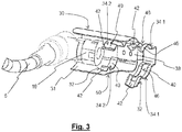
- the figure 3 is a detailed perspective view of the thermal protection device according to the present invention extending around a connector of the SCR system.
- the figure 1 shows a catalytic reduction system 1, also called SCR system (acronym for "Selective Catalytic Reduction” in English), comprising at least one reservoir 2 for storage of a reducing agent in liquid form, a pump 3 generally reversible, and at least one pipe 5 connecting the pump 3 to an injector 8 for injecting reducing agent into an exhaust line 10 of a heat engine.
- the injector 8 is positioned upstream of a catalyst 11.
- the reservoir 2 contains a level sensor 14, a temperature sensor 15, and heating resistors 16 belonging to a de-icing system.
- This deicing system further comprises a resistive wire 18 positioned along the pipe 5.
- the injector 8 comprises a body 23 and a connecting piece 24.
- the connection piece 24 fixed to the body 23 is connected to one end of the pipe 5 via a connector 19.
- This connector 19 is for example a snap-in connector fast (called "Quick Connect" in English).
- the body 23 has a front end 231 adapted to cooperate with a complementary shaped interface for attachment to the exhaust line 10 by means of a clamp.
- a connector 25 is intended to provide power and control of the injector 8.
- a thermal protection device 30 comprises a cover 31 surrounding at least part of the connecting end 24 of the injector 8 and the connector 19 of the pipe 5. This cover 31 is associated with a fastening device 32 snapped onto the body 23 of the injector 8.
- the cover 31 has two walls facing each other interconnected by a connecting wall so as to have a generally U-shaped.
- the cover 31 is made of a thermally conductive material, in particular metal. This makes it possible to recover the heat generated by the exhaust line 10 (the injector having its end 231 in contact with the line 10) and to route it by conduction in the cold zone constituted by the connector end assembly 24. and connector 19.
- the snap-fastening device 32 comprises two generally C-shaped clips 34.1, 34.2 coming from a support 38 fixed on an internal face of the cover. 31.
- the clamps 34.1, 34.2 are monoblock with the support 38 coming from material of the same piece.
- the clamps 34.1, 34.2 are located on either side of the connector 25 but they could alternatively be located on the same side of the connector 25.
- each clamp 34.1, 34.2 C-shaped is provided with two arms 40 elastically deformable located vis-à-vis one with respect to the other.
- the free ends of the arms 40 are spaced relative to each other to allow the insertion of the body 23 of the injector 8 between the arms 40 by elastic deformation of the arms 40.
- a smaller dimension between the two arms 40 of the clamp 34.1, 34.2 is smaller than the largest dimension of the body 23 of the injector 8 in the corresponding detent zone intended to receive the clamp 34.1, 34.2 .
- the arms 40 of the clamp 34.1, 34.2 deviate with respect to each other by elastic deformation during the insertion of the injector 8, then move closer to one another. the other so as to grip a portion of the outer circumference of the body 23 of the injector 8.
- the correct positioning of the cover 31 can be controlled by the sound produced by the metal part 30 when the injector 8 enters into contact with the bottom of the hood 31.
- each arm 40 of the clamp 34.1, 34.2 has a spout 42 on the side of its free end forming a non-zero angle with the portion of the arm 40 intended to be positioned around the body 23 of the injector 8.
- the two spouts 42 clamp 34.1, 34.2 delimit a flared opening facilitating the installation of the thermal protection device 30.
- the clamp 34.1 is intended to cooperate with a projecting rib 44 from the body 23 of the injector 8 which has an annular shape.
- the arms 40 of the clamp 34.1 each comprise a window 46 intended to receive the rib 44 formed in the latching zone.
- the connection between the rib 44 and the window 46 makes it possible to lock the hood 31 in translation.
- the window 46 advantageously extends to the spouts 42 to allow the clamps 34.1 to be centered on the rib 44 of the injector 8. .
- the clamp 34.2 is intended to cooperate with a flat portion 48 formed in the body 23 of the injector 8.
- the arms 40 of the clamp 34.2 have different widths in order to play a keying role during the installation of the hood 31.
- the 34.2 clamp has the function of locking the device 30 on the body 23 of the injector 8 by blocking the possible movement in the degrees of freedom left by the clamp 34.1.
- a notch 50 is formed in an edge of the cover 31 to allow the passage of the connector 25. The latter, because of its support against an edge of the notch 50, provides a locking rotation of the cover 31 around the l 25 connector axis.
Landscapes
- Engineering & Computer Science (AREA)
- Chemical & Material Sciences (AREA)
- Chemical Kinetics & Catalysis (AREA)
- Combustion & Propulsion (AREA)
- Mechanical Engineering (AREA)
- General Engineering & Computer Science (AREA)
- Health & Medical Sciences (AREA)
- Toxicology (AREA)
- Exhaust Gas After Treatment (AREA)
Abstract
- un injecteur (8) apte à injecter une quantité d'agent réducteur,
- l'injecteur (8) ayant un corps (23) et un embout de connexion (24) coopérant avec un connecteur d'une canalisation acheminant l'agent réducteur jusqu'audit injecteur (8), caractérisé en ce que ledit système de réduction catalytique comporte en outre un dispositif de protection thermique (30) comprenant:
- un capot (31) entourant au moins en partie l'embout de connexion (24) de l'injecteur (8) et le connecteur de la canalisation, et
- un dispositif de fixation (32) par encliquetage sur le corps (23) de l'injecteur (8).
Description
- La présente invention porte sur un système de réduction sélective catalytique, dit aussi système SCR (acronyme pour "Selective Catalytic Réduction" en anglais), muni d'un dispositif de protection thermique. L'invention trouve une application particulièrement avantageuse lors du fonctionnement dans des conditions sévères des systèmes SCR de type liquide équipant les véhicules à moteur diesel.
- Dans un contexte de dépollution des gaz d'échappement du moteur, les systèmes SCR visent à réduire les oxydes d'azote (NOx) contenus dans les gaz d'échappement. Les systèmes SCR mettent en oeuvre une réaction chimique entre les oxydes d'azote et un agent réducteur prenant classiquement la forme d'ammoniac.
- L'injection de l'ammoniac dans la ligne d'échappement des gaz est généralement réalisée par l'intermédiaire d'un précurseur, tel que l'urée qui se décompose en ammoniac et en dioxyde de carbone sous l'effet de la chaleur.
- Les systèmes utilisant un agent réducteur sous forme liquide comporte un système de dégivrage pour permettre un fonctionnement en dessous de la température de solidification de l'agent réducteur (de l'ordre de -11°C). Le système de dégivrage est constitué de résistances chauffantes situées dans le réservoir et d'un fil résistif positionné le long de la canalisation. On prévoit également une purge du système à la fin de chaque roulage pour éviter le gel de l'agent réducteur lors du stationnement susceptible d'engendrer la casse de l'injecteur.
- Toutefois, dans certaines architectures de véhicule, l'injecteur est exposé à des flux aérauliques importants, en sorte que pour certains points de fonctionnement (à températures froides et vitesses élevées) des portions gelées d'agent réducteur sont susceptibles de se former au niveau de l'embout de connexion de l'injecteur avec la canalisation du système SCR car les résistances chauffantes ne s'étendent pas dans cette zone. Cette formation de glaçons empêche alors l'injection d'agent réducteur, ainsi qu'une purge correcte du circuit en fin de roulage.
- Pour éviter ce phénomène, un dispositif isolant flexible de type chaussette vient isoler l'embout de connexion de l'injecteur ainsi que le connecteur correspondant. Toutefois, cette chaussette arrivant livrée en bord de ligne de montage, elle nécessite une phase finale de pliage avant d'être montée complétement sur l'extrémité de la canalisation SCR et de la zone de connexion sur injecteur SCR. Cette opération impose une méthodologie de mise en place associée à un contrôle visuel qui est longue et coûteuse à mettre en oeuvre en usine de fabrication. En outre, certains environnements en zone Injecteur et échappement présentent des contraintes d'encombrement telles, qu'il n'est pas possible d'installer la chaussette isolante autour de l'embout de connexion de l'injecteur.
- L'invention vise à remédier efficacement à cet inconvénient en proposant un système de réduction catalytique pour une ligne d'échappement de moteur thermique comportant:
- un injecteur apte à injecter une quantité d'agent réducteur,
- l'injecteur ayant un corps et un embout de connexion coopérant avec un connecteur d'une canalisation acheminant l'agent réducteur jusqu'audit injecteur, caractérisé en ce que ledit système de réduction catalytique comporte en outre un dispositif de protection thermique comprenant:
- un capot entourant au moins en partie l'embout de connexion de l'injecteur et le connecteur de la canalisation, et
- un dispositif de fixation par encliquetage sur le corps de l'injecteur.
- L'invention permet ainsi, grâce à la fixation par encliquetage, de faciliter le montage du dispositif sur l'injecteur et d'autoriser son implantation dans des environnements à fortes contraintes d'encombrement. L'invention permet également de réduire la durée allouée à l'assemblage du dispositif, dans la mesure où elle ne nécessite pas de préparation hors ligne comme cela est le cas avec une chaussette isolante. L'invention présente également l'avantage de s'assurer de la mise en place correcte du dispositif sur l'injecteur par un contrôle auditif. L'invention présente également un caractère économique car son prix de revient est faible.
- Selon une réalisation, le capot comporte deux parois en regard l'une de l'autre reliées entre elles par une paroi de liaison de manière à présenter globalement une forme en U.
- Selon une réalisation, le capot est réalisé dans un matériau thermiquement conducteur, notamment en métal.
- Selon une réalisation, le dispositif de fixation par encliquetage comporte au moins une pince munie de deux bras élastiquement déformables situés en vis-à-vis l'un par rapport à l'autre.
- Selon une réalisation, chaque bras de la pince comporte un bec du côté de son extrémité libre.
- Selon une réalisation, le dispositif de fixation par encliquetage comporte une première et une deuxième pinces.
- Selon une réalisation, la première pince coopère avec une nervure issue du corps de l'injecteur.
- Selon une réalisation, les bras de la première pince comportent chacun une fenêtre recevant la nervure ménagée dans la zone d'encliquetage.
- Selon une réalisation, la deuxième pince coopère avec un méplat ménagé dans le corps de l'injecteur.
- L'invention a également pour objet une ligne d'échappement comportant un système de réduction catalytique tel que défini précédemment.
- L'invention a également pour objet un véhicule, notamment automobile, intégrant une ligne d'échappement telle que définie précédemment.
- L'invention sera mieux comprise à la lecture de la description qui suit et à l'examen des figures qui l'accompagnent. Ces figures ne sont données qu'à titre illustratif mais nullement limitatif de l'invention.
- La
figure 1 est une représentation schématique d'un système de réduction sélective catalytique selon la présente invention; - La
figure 2 est une vue en perspective détaillée d'un dispositif de protection thermique selon la présente invention monté sur un injecteur du système de réduction sélective catalytique; - La
figure 3 est une vue en perspective détaillée du dispositif de protection thermique selon la présente invention s'étendant autour d'un connecteur du système SCR. - Les éléments identiques, similaires, ou analogues conservent la même référence d'une figure à l'autre.
- La
figure 1 montre un système de réduction catalytique 1, dit aussi système SCR (acronyme pour "Selective Catalytic Réduction" en anglais), comportant au moins un réservoir 2 de stockage d'un agent réducteur sous forme liquide, une pompe 3 généralement réversible, ainsi qu'au moins une canalisation 5 reliant la pompe 3 à un injecteur 8 destiné à injecter de l'agent réducteur dans une ligne d'échappement 10 de moteur thermique. L'injecteur 8 est positionné en amont d'un catalyseur 11. En outre, le réservoir 2 contient un capteur de niveau 14, un capteur de température 15, et des résistances chauffantes 16 appartenant à un système de dégivrage. Ce système de dégivrage comporte en outre un fil résistif 18 positionné le long de la canalisation 5. - Comme cela est représenté sur la
figure 2 , l'injecteur 8 comprend un corps 23 et un embout de connexion 24. L'embout de connexion 24 fixé sur le corps 23 est connecté à une extrémité de la canalisation 5 via un connecteur 19. Ce connecteur 19 est par exemple un connecteur encliquetable rapide (dit "Quick Connect" en anglais). - Le corps 23 comporte une extrémité avant 231 adaptée à coopérer avec une interface de forme complémentaire pour sa fixation sur la ligne d'échappement 10 au moyen d'un collier de serrage. En outre, un connecteur 25 est destiné à assurer l'alimentation et le pilotage de l'injecteur 8.
- Comme cela est représenté sur les
figures 2 et3 , un dispositif de protection thermique 30 comporte un capot 31 entourant au moins en partie l'embout de connexion 24 de l'injecteur 8 et le connecteur 19 de la canalisation 5. Ce capot 31 est associé à un dispositif de fixation 32 par encliquetage sur le corps 23 de l'injecteur 8. - Le capot 31 comporte deux parois en regard l'une de l'autre reliées entre elles par une paroi de liaison de manière à présenter globalement une forme en U. Le capot 31 est réalisé dans un matériau thermiquement conducteur, notamment en métal. Cela permet de récupérer de la chaleur générée par la ligne d'échappement 10 (l'injecteur présentant son extrémité 231 en contact avec la ligne 10) et de l'acheminer par conduction dans la zone froide constituée par l'ensemble embout de connexion 24 et connecteur 19.
- Par ailleurs, le dispositif de fixation par encliquetage 32 comporte deux pinces 34.1, 34.2 globalement en forme de C issues d'un support 38 fixé sur une face interne du capot 31. En variante, les pinces 34.1, 34.2 sont monoblocs avec le support 38 en venant de matière de la même pièce. En l'occurrence, les pinces 34.1, 34.2 sont situées de part et d'autre du connecteur 25 mais elles pourraient alternativement être situées d'un même côté du connecteur 25.
- Plus précisément, chaque pince 34.1, 34.2 en forme de C est munie de deux bras 40 élastiquement déformables situés en vis-à-vis l'un par rapport à l'autre. Les extrémités libres des bras 40 sont espacées l'une par rapport à l'autre pour permettre l'insertion du corps 23 de l'injecteur 8 entre les bras 40 par déformation élastique des bras 40.
- En position non contrainte, une plus petite dimension entre les deux bras 40 de la pince 34.1, 34.2 est inférieure à la plus grande dimension du corps 23 de l'injecteur 8 dans la zone d'encliquetage correspondante destinée à recevoir la pince 34.1, 34.2. Lors la mise en place du capot 31, les bras 40 de la pince 34.1, 34.2 s'écartent l'un par rapport à l'autre par déformation élastique lors de l'insertion de l'injecteur 8, puis se rapprochent l'un de l'autre de manière à enserrer une portion de la circonférence externe du corps 23 de l'injecteur 8. La mise en place correcte du capot 31 peut être contrôlée par le son que produit la pièce métallique 30 lorsque l'injecteur 8 entre en contact avec le fond du capot 31.
- Avantageusement, chaque bras 40 de la pince 34.1, 34.2 comporte un bec 42 du côté de son extrémité libre formant un angle non nul avec la portion du bras 40 destinée à être positionnée autour du corps 23 de l'injecteur 8. Les deux becs 42 de la pince 34.1, 34.2 délimitent une ouverture évasée facilitant l'installation du dispositif de protection thermique 30.
- Comme on peut le voir sur la
figure 2 , la pince 34.1 est destinée à coopérer avec une nervure saillante 44 issue du corps 23 de l'injecteur 8 qui présente une forme annulaire. A cet effet, les bras 40 de la pince 34.1 comportent chacun une fenêtre 46 destinée à recevoir la nervure 44 ménagée dans la zone d'encliquetage. La liaison entre la nervure 44 et la fenêtre 46 permet d'assurer un blocage en translation du capot 31. La fenêtre 46 s'étend avantageusement jusqu'aux becs 42 pour permettre le centrage des pinces 34.1 sur la nervure 44 de l'injecteur 8. - Par ailleurs, la pince 34.2 est destinée à coopérer avec un méplat 48 ménagé dans le corps 23 de l'injecteur 8. Les bras 40 de la pince 34.2 présentent des largeurs différentes afin de jouer un rôle de détrompeur lors de l'installation du capot 31. La pince 34.2 a pour fonction de verrouiller le dispositif 30 sur le corps 23 de l'injecteur 8 en bloquant le mouvement possible dans les degrés de liberté laissés par la pince 34.1.
- En outre, une échancrure 50 est ménagée dans un bord du capot 31 pour autoriser le passage du connecteur 25. Ce dernier, du fait de son appui contre un bord de l'échancrure 50, assure un blocage en rotation du capot 31 autour de l'axe du connecteur 25.
- En variante, dans un mode de réalisation dégradé, on prévoit une seule pince de fixation 34.1, 34.2 pour fixer le capot 31 sur l'injecteur 8.
Claims (10)
- Système de réduction catalytique (1) pour une ligne d'échappement (10) de moteur thermique comportant:- un injecteur (8) apte à injecter une quantité d'agent réducteur,- l'injecteur (8) ayant un corps (23) et un embout de connexion (24) coopérant avec un connecteur (19) d'une canalisation (5) acheminant l'agent réducteur jusqu'audit injecteur (8), caractérisé en ce que ledit système de réduction catalytique (1) comporte en outre un dispositif de protection thermique (30) comprenant:ledit capot (31) étant réalisé dans un matériau thermiquement conducteur et conformer pour récupérer de la chaleur générée par ladite ligne d'échappement (10) et l'acheminer par conduction dans la zone froide constituée par l'ensemble embout de connexion (24) et connecteur (19).- un capot (31) entourant au moins en partie l'embout de connexion (24) de l'injecteur (8) et le connecteur (19) de la canalisation (5), et- un dispositif de fixation (32) par encliquetage sur le corps (23) de l'injecteur (8),
- Système selon la revendication 1, caractérisé en ce que le capot (31) comporte deux parois en regard l'une de l'autre reliées entre elles par une paroi de liaison de manière à présenter globalement une forme en U.
- Système selon la revendication 1 ou 2, caractérisé en ce que le capot (31) est réalisé dans un matériau thermiquement conducteur, notamment en métal.
- Système selon l'une quelconque des revendications 1 à 3, caractérisé en ce que le dispositif de fixation (32) par encliquetage comporte au moins une pince (34.1, 34.2) munie de deux bras (40) élastiquement déformables situés en vis-à-vis l'un par rapport à l'autre.
- Système selon la revendication 4, caractérisé en ce que chaque bras (40) de la pince (34.1, 34.2) comporte un bec (42) du côté de son extrémité libre.
- Système selon la revendication 4 ou 5, caractérisé en ce que le dispositif de fixation (32) par encliquetage comporte une première (34.1) et une deuxième (34.2) pinces.
- Système selon la revendication 6, caractérisé en ce que la première pince (34.1) coopère avec une nervure (44) issue du corps (23) de l'injecteur (8).
- Système selon la revendication 7, caractérisé en ce que les bras (40) de la première pince (34.1) comportent chacun une fenêtre (46) recevant la nervure (44) ménagée dans la zone d'encliquetage.
- Système selon l'une quelconque des revendications 6 à 8, caractérisé en ce que la deuxième pince (34.2) coopère avec un méplat (48) ménagé dans le corps (23) de l'injecteur (8).
- Ligne d'échappement (10) comportant un système de réduction catalytique (1) tel que défini selon l'une quelconque des revendications 1 à 9.
Applications Claiming Priority (1)
| Application Number | Priority Date | Filing Date | Title |
|---|---|---|---|
| FR1756795A FR3069280A1 (fr) | 2017-07-18 | 2017-07-18 | Systeme de reduction selective catalytique muni d'un dispositif de protection thermique |
Publications (2)
| Publication Number | Publication Date |
|---|---|
| EP3431729A1 true EP3431729A1 (fr) | 2019-01-23 |
| EP3431729B1 EP3431729B1 (fr) | 2020-04-01 |
Family
ID=59930557
Family Applications (1)
| Application Number | Title | Priority Date | Filing Date |
|---|---|---|---|
| EP18179836.4A Active EP3431729B1 (fr) | 2017-07-18 | 2018-06-26 | Systeme de reduction selective catalytique muni d'un dispositif de protection thermique |
Country Status (2)
| Country | Link |
|---|---|
| EP (1) | EP3431729B1 (fr) |
| FR (1) | FR3069280A1 (fr) |
Cited By (1)
| Publication number | Priority date | Publication date | Assignee | Title |
|---|---|---|---|---|
| FR3116300A1 (fr) * | 2020-11-17 | 2022-05-20 | Psa Automobiles Sa | Systeme de reduction catalytique avec dispositif de protection thermique |
Citations (2)
| Publication number | Priority date | Publication date | Assignee | Title |
|---|---|---|---|---|
| DE19625447A1 (de) * | 1996-06-26 | 1998-01-02 | Bosch Gmbh Robert | Rohrverdampfer für Zusatzkraftstoff ins Abgas |
| US20090107126A1 (en) * | 2007-10-25 | 2009-04-30 | Continental Automotive Systems Us, Inc. | Fluid supply connection for reductant delivery unit for selective catalytic reduction systems |
-
2017
- 2017-07-18 FR FR1756795A patent/FR3069280A1/fr not_active Ceased
-
2018
- 2018-06-26 EP EP18179836.4A patent/EP3431729B1/fr active Active
Patent Citations (2)
| Publication number | Priority date | Publication date | Assignee | Title |
|---|---|---|---|---|
| DE19625447A1 (de) * | 1996-06-26 | 1998-01-02 | Bosch Gmbh Robert | Rohrverdampfer für Zusatzkraftstoff ins Abgas |
| US20090107126A1 (en) * | 2007-10-25 | 2009-04-30 | Continental Automotive Systems Us, Inc. | Fluid supply connection for reductant delivery unit for selective catalytic reduction systems |
Cited By (2)
| Publication number | Priority date | Publication date | Assignee | Title |
|---|---|---|---|---|
| FR3116300A1 (fr) * | 2020-11-17 | 2022-05-20 | Psa Automobiles Sa | Systeme de reduction catalytique avec dispositif de protection thermique |
| EP4001603A1 (fr) * | 2020-11-17 | 2022-05-25 | PSA Automobiles SA | Systeme de reduction catalytique avec dispositif de protection thermique |
Also Published As
| Publication number | Publication date |
|---|---|
| FR3069280A1 (fr) | 2019-01-25 |
| EP3431729B1 (fr) | 2020-04-01 |
Similar Documents
| Publication | Publication Date | Title |
|---|---|---|
| EP1188974B1 (fr) | Dispositif doseur autonettoyant | |
| WO2004097192A2 (fr) | Echappement pour moteur a combustion interne | |
| FR2848957A1 (fr) | Bras d'essuie-glace pour un dispositif d'essuie-glace de vehicule | |
| EP2803543B1 (fr) | Interface de connexion hydraulique et/ou électrique pour balai d'essuie-glace | |
| FR2966651A1 (fr) | Dispositif d'entretoisement de harnais electriques dans une turbomachine | |
| EP3431729B1 (fr) | Systeme de reduction selective catalytique muni d'un dispositif de protection thermique | |
| EP0396455B1 (fr) | Dispositif d'assemblage par encliquetage pour échangeurs de chaleur de véhicules automobiles | |
| EP2969623B1 (fr) | Valise de refroidissement comportant des moyens de rattrapage des dispersions de fabrication | |
| EP0501852A1 (fr) | Dispositif de fixation d'un organe tubulaire sur un embout tubulaire de raccordement d'un composant, notamment de véhicule automobile | |
| EP4001603A1 (fr) | Systeme de reduction catalytique avec dispositif de protection thermique | |
| FR2897646A3 (fr) | Composant de ligne d'echappement | |
| EP2953841A1 (fr) | Support multifonction pour la fixation de plusieurs pieces sur le châssis d'un vehicule | |
| FR3107728A1 (fr) | Dispositif de purification de gaz d’échappement à chauffage optimisé | |
| EP2607187B1 (fr) | Interface hydraulique d'un dispositif d'essuyage d'une vitre d'un véhicule automobile | |
| WO2009077431A1 (fr) | Pot catalytique | |
| FR2925630A1 (fr) | Dispositif de fixation, du type agrafe, pour le montage d'un element amovible sur un support | |
| EP2923872A1 (fr) | Ensemble pour châssis de véhicule automobile à double écrans de protection thermique | |
| EP3126647B1 (fr) | Suspente d'échappement de véhicule automobile | |
| FR2887321A1 (fr) | Ensemble a tube de raccordement souple et collier de serrage entourant une partie d'extremite du tube | |
| EP3359423B1 (fr) | Ensemble pour châssis de vehicule automobile | |
| FR3022582A1 (fr) | Systeme de reduction selective catalytique muni d'un insert caloduc sur son injecteur | |
| EP1908967B1 (fr) | Dispositif de fixation d'un câble dans une platine support | |
| FR2927132A1 (fr) | Dispositif de fixation ayant une piece de support et une ceinture | |
| FR2981692A1 (fr) | Systeme d echappement d un vehicule automobile | |
| EP3012163A1 (fr) | Dispositif de projection de liquide lave-glace pour un balai d essuyage de système d essuie-glace de véhicule |
Legal Events
| Date | Code | Title | Description |
|---|---|---|---|
| PUAI | Public reference made under article 153(3) epc to a published international application that has entered the european phase |
Free format text: ORIGINAL CODE: 0009012 |
|
| STAA | Information on the status of an ep patent application or granted ep patent |
Free format text: STATUS: THE APPLICATION HAS BEEN PUBLISHED |
|
| AK | Designated contracting states |
Kind code of ref document: A1 Designated state(s): AL AT BE BG CH CY CZ DE DK EE ES FI FR GB GR HR HU IE IS IT LI LT LU LV MC MK MT NL NO PL PT RO RS SE SI SK SM TR |
|
| AX | Request for extension of the european patent |
Extension state: BA ME |
|
| STAA | Information on the status of an ep patent application or granted ep patent |
Free format text: STATUS: REQUEST FOR EXAMINATION WAS MADE |
|
| 17P | Request for examination filed |
Effective date: 20190626 |
|
| RBV | Designated contracting states (corrected) |
Designated state(s): AL AT BE BG CH CY CZ DE DK EE ES FI FR GB GR HR HU IE IS IT LI LT LU LV MC MK MT NL NO PL PT RO RS SE SI SK SM TR |
|
| GRAP | Despatch of communication of intention to grant a patent |
Free format text: ORIGINAL CODE: EPIDOSNIGR1 |
|
| STAA | Information on the status of an ep patent application or granted ep patent |
Free format text: STATUS: GRANT OF PATENT IS INTENDED |
|
| INTG | Intention to grant announced |
Effective date: 20191031 |
|
| GRAS | Grant fee paid |
Free format text: ORIGINAL CODE: EPIDOSNIGR3 |
|
| GRAA | (expected) grant |
Free format text: ORIGINAL CODE: 0009210 |
|
| STAA | Information on the status of an ep patent application or granted ep patent |
Free format text: STATUS: THE PATENT HAS BEEN GRANTED |
|
| AK | Designated contracting states |
Kind code of ref document: B1 Designated state(s): AL AT BE BG CH CY CZ DE DK EE ES FI FR GB GR HR HU IE IS IT LI LT LU LV MC MK MT NL NO PL PT RO RS SE SI SK SM TR |
|
| REG | Reference to a national code |
Ref country code: GB Ref legal event code: FG4D Free format text: NOT ENGLISH |
|
| REG | Reference to a national code |
Ref country code: CH Ref legal event code: EP Ref country code: AT Ref legal event code: REF Ref document number: 1251610 Country of ref document: AT Kind code of ref document: T Effective date: 20200415 |
|
| REG | Reference to a national code |
Ref country code: DE Ref legal event code: R096 Ref document number: 602018003393 Country of ref document: DE |
|
| REG | Reference to a national code |
Ref country code: IE Ref legal event code: FG4D Free format text: LANGUAGE OF EP DOCUMENT: FRENCH |
|
| PG25 | Lapsed in a contracting state [announced via postgrant information from national office to epo] |
Ref country code: BG Free format text: LAPSE BECAUSE OF FAILURE TO SUBMIT A TRANSLATION OF THE DESCRIPTION OR TO PAY THE FEE WITHIN THE PRESCRIBED TIME-LIMIT Effective date: 20200701 |
|
| REG | Reference to a national code |
Ref country code: NL Ref legal event code: MP Effective date: 20200401 |
|
| REG | Reference to a national code |
Ref country code: LT Ref legal event code: MG4D Ref country code: DE Ref legal event code: R084 Ref document number: 602018003393 Country of ref document: DE |
|
| PG25 | Lapsed in a contracting state [announced via postgrant information from national office to epo] |
Ref country code: LT Free format text: LAPSE BECAUSE OF FAILURE TO SUBMIT A TRANSLATION OF THE DESCRIPTION OR TO PAY THE FEE WITHIN THE PRESCRIBED TIME-LIMIT Effective date: 20200401 Ref country code: CZ Free format text: LAPSE BECAUSE OF FAILURE TO SUBMIT A TRANSLATION OF THE DESCRIPTION OR TO PAY THE FEE WITHIN THE PRESCRIBED TIME-LIMIT Effective date: 20200401 Ref country code: PT Free format text: LAPSE BECAUSE OF FAILURE TO SUBMIT A TRANSLATION OF THE DESCRIPTION OR TO PAY THE FEE WITHIN THE PRESCRIBED TIME-LIMIT Effective date: 20200817 Ref country code: NL Free format text: LAPSE BECAUSE OF FAILURE TO SUBMIT A TRANSLATION OF THE DESCRIPTION OR TO PAY THE FEE WITHIN THE PRESCRIBED TIME-LIMIT Effective date: 20200401 Ref country code: FI Free format text: LAPSE BECAUSE OF FAILURE TO SUBMIT A TRANSLATION OF THE DESCRIPTION OR TO PAY THE FEE WITHIN THE PRESCRIBED TIME-LIMIT Effective date: 20200401 Ref country code: NO Free format text: LAPSE BECAUSE OF FAILURE TO SUBMIT A TRANSLATION OF THE DESCRIPTION OR TO PAY THE FEE WITHIN THE PRESCRIBED TIME-LIMIT Effective date: 20200701 Ref country code: GR Free format text: LAPSE BECAUSE OF FAILURE TO SUBMIT A TRANSLATION OF THE DESCRIPTION OR TO PAY THE FEE WITHIN THE PRESCRIBED TIME-LIMIT Effective date: 20200702 Ref country code: IS Free format text: LAPSE BECAUSE OF FAILURE TO SUBMIT A TRANSLATION OF THE DESCRIPTION OR TO PAY THE FEE WITHIN THE PRESCRIBED TIME-LIMIT Effective date: 20200801 Ref country code: SE Free format text: LAPSE BECAUSE OF FAILURE TO SUBMIT A TRANSLATION OF THE DESCRIPTION OR TO PAY THE FEE WITHIN THE PRESCRIBED TIME-LIMIT Effective date: 20200401 |
|
| RAP2 | Party data changed (patent owner data changed or rights of a patent transferred) |
Owner name: PSA AUTOMOBILES SA |
|
| REG | Reference to a national code |
Ref country code: AT Ref legal event code: MK05 Ref document number: 1251610 Country of ref document: AT Kind code of ref document: T Effective date: 20200401 |
|
| PG25 | Lapsed in a contracting state [announced via postgrant information from national office to epo] |
Ref country code: HR Free format text: LAPSE BECAUSE OF FAILURE TO SUBMIT A TRANSLATION OF THE DESCRIPTION OR TO PAY THE FEE WITHIN THE PRESCRIBED TIME-LIMIT Effective date: 20200401 Ref country code: RS Free format text: LAPSE BECAUSE OF FAILURE TO SUBMIT A TRANSLATION OF THE DESCRIPTION OR TO PAY THE FEE WITHIN THE PRESCRIBED TIME-LIMIT Effective date: 20200401 Ref country code: LV Free format text: LAPSE BECAUSE OF FAILURE TO SUBMIT A TRANSLATION OF THE DESCRIPTION OR TO PAY THE FEE WITHIN THE PRESCRIBED TIME-LIMIT Effective date: 20200401 |
|
| PG25 | Lapsed in a contracting state [announced via postgrant information from national office to epo] |
Ref country code: AL Free format text: LAPSE BECAUSE OF FAILURE TO SUBMIT A TRANSLATION OF THE DESCRIPTION OR TO PAY THE FEE WITHIN THE PRESCRIBED TIME-LIMIT Effective date: 20200401 |
|
| REG | Reference to a national code |
Ref country code: DE Ref legal event code: R097 Ref document number: 602018003393 Country of ref document: DE |
|
| PG25 | Lapsed in a contracting state [announced via postgrant information from national office to epo] |
Ref country code: IT Free format text: LAPSE BECAUSE OF FAILURE TO SUBMIT A TRANSLATION OF THE DESCRIPTION OR TO PAY THE FEE WITHIN THE PRESCRIBED TIME-LIMIT Effective date: 20200401 Ref country code: RO Free format text: LAPSE BECAUSE OF FAILURE TO SUBMIT A TRANSLATION OF THE DESCRIPTION OR TO PAY THE FEE WITHIN THE PRESCRIBED TIME-LIMIT Effective date: 20200401 Ref country code: SM Free format text: LAPSE BECAUSE OF FAILURE TO SUBMIT A TRANSLATION OF THE DESCRIPTION OR TO PAY THE FEE WITHIN THE PRESCRIBED TIME-LIMIT Effective date: 20200401 Ref country code: ES Free format text: LAPSE BECAUSE OF FAILURE TO SUBMIT A TRANSLATION OF THE DESCRIPTION OR TO PAY THE FEE WITHIN THE PRESCRIBED TIME-LIMIT Effective date: 20200401 Ref country code: MC Free format text: LAPSE BECAUSE OF FAILURE TO SUBMIT A TRANSLATION OF THE DESCRIPTION OR TO PAY THE FEE WITHIN THE PRESCRIBED TIME-LIMIT Effective date: 20200401 Ref country code: AT Free format text: LAPSE BECAUSE OF FAILURE TO SUBMIT A TRANSLATION OF THE DESCRIPTION OR TO PAY THE FEE WITHIN THE PRESCRIBED TIME-LIMIT Effective date: 20200401 Ref country code: EE Free format text: LAPSE BECAUSE OF FAILURE TO SUBMIT A TRANSLATION OF THE DESCRIPTION OR TO PAY THE FEE WITHIN THE PRESCRIBED TIME-LIMIT Effective date: 20200401 Ref country code: DK Free format text: LAPSE BECAUSE OF FAILURE TO SUBMIT A TRANSLATION OF THE DESCRIPTION OR TO PAY THE FEE WITHIN THE PRESCRIBED TIME-LIMIT Effective date: 20200401 |
|
| PLBE | No opposition filed within time limit |
Free format text: ORIGINAL CODE: 0009261 |
|
| STAA | Information on the status of an ep patent application or granted ep patent |
Free format text: STATUS: NO OPPOSITION FILED WITHIN TIME LIMIT |
|
| PG25 | Lapsed in a contracting state [announced via postgrant information from national office to epo] |
Ref country code: SK Free format text: LAPSE BECAUSE OF FAILURE TO SUBMIT A TRANSLATION OF THE DESCRIPTION OR TO PAY THE FEE WITHIN THE PRESCRIBED TIME-LIMIT Effective date: 20200401 Ref country code: PL Free format text: LAPSE BECAUSE OF FAILURE TO SUBMIT A TRANSLATION OF THE DESCRIPTION OR TO PAY THE FEE WITHIN THE PRESCRIBED TIME-LIMIT Effective date: 20200401 |
|
| 26N | No opposition filed |
Effective date: 20210112 |
|
| REG | Reference to a national code |
Ref country code: GB Ref legal event code: 746 Effective date: 20210302 |
|
| PG25 | Lapsed in a contracting state [announced via postgrant information from national office to epo] |
Ref country code: LU Free format text: LAPSE BECAUSE OF NON-PAYMENT OF DUE FEES Effective date: 20200626 |
|
| REG | Reference to a national code |
Ref country code: BE Ref legal event code: MM Effective date: 20200630 |
|
| PG25 | Lapsed in a contracting state [announced via postgrant information from national office to epo] |
Ref country code: IE Free format text: LAPSE BECAUSE OF NON-PAYMENT OF DUE FEES Effective date: 20200626 |
|
| PG25 | Lapsed in a contracting state [announced via postgrant information from national office to epo] |
Ref country code: SI Free format text: LAPSE BECAUSE OF FAILURE TO SUBMIT A TRANSLATION OF THE DESCRIPTION OR TO PAY THE FEE WITHIN THE PRESCRIBED TIME-LIMIT Effective date: 20200401 Ref country code: BE Free format text: LAPSE BECAUSE OF NON-PAYMENT OF DUE FEES Effective date: 20200630 |
|
| REG | Reference to a national code |
Ref country code: CH Ref legal event code: PL |
|
| PG25 | Lapsed in a contracting state [announced via postgrant information from national office to epo] |
Ref country code: LI Free format text: LAPSE BECAUSE OF NON-PAYMENT OF DUE FEES Effective date: 20210630 Ref country code: CH Free format text: LAPSE BECAUSE OF NON-PAYMENT OF DUE FEES Effective date: 20210630 |
|
| PG25 | Lapsed in a contracting state [announced via postgrant information from national office to epo] |
Ref country code: TR Free format text: LAPSE BECAUSE OF FAILURE TO SUBMIT A TRANSLATION OF THE DESCRIPTION OR TO PAY THE FEE WITHIN THE PRESCRIBED TIME-LIMIT Effective date: 20200401 Ref country code: MT Free format text: LAPSE BECAUSE OF FAILURE TO SUBMIT A TRANSLATION OF THE DESCRIPTION OR TO PAY THE FEE WITHIN THE PRESCRIBED TIME-LIMIT Effective date: 20200401 Ref country code: CY Free format text: LAPSE BECAUSE OF FAILURE TO SUBMIT A TRANSLATION OF THE DESCRIPTION OR TO PAY THE FEE WITHIN THE PRESCRIBED TIME-LIMIT Effective date: 20200401 |
|
| PG25 | Lapsed in a contracting state [announced via postgrant information from national office to epo] |
Ref country code: MK Free format text: LAPSE BECAUSE OF FAILURE TO SUBMIT A TRANSLATION OF THE DESCRIPTION OR TO PAY THE FEE WITHIN THE PRESCRIBED TIME-LIMIT Effective date: 20200401 |
|
| REG | Reference to a national code |
Ref country code: DE Ref legal event code: R081 Ref document number: 602018003393 Country of ref document: DE Owner name: STELLANTIS AUTO SAS, FR Free format text: FORMER OWNER: PSA AUTOMOBILES SA, POISSY, FR |
|
| PGFP | Annual fee paid to national office [announced via postgrant information from national office to epo] |
Ref country code: GB Payment date: 20260525 Year of fee payment: 9 |
|
| PGFP | Annual fee paid to national office [announced via postgrant information from national office to epo] |
Ref country code: DE Payment date: 20260520 Year of fee payment: 9 |
|
| PGFP | Annual fee paid to national office [announced via postgrant information from national office to epo] |
Ref country code: FR Payment date: 20260520 Year of fee payment: 9 |