EP3431636A2 - Anodization of bonded assembly - Google Patents
Anodization of bonded assembly Download PDFInfo
- Publication number
- EP3431636A2 EP3431636A2 EP18181625.7A EP18181625A EP3431636A2 EP 3431636 A2 EP3431636 A2 EP 3431636A2 EP 18181625 A EP18181625 A EP 18181625A EP 3431636 A2 EP3431636 A2 EP 3431636A2
- Authority
- EP
- European Patent Office
- Prior art keywords
- component
- electrode
- bonded assembly
- bonded
- metal
- Prior art date
- Legal status (The legal status is an assumption and is not a legal conclusion. Google has not performed a legal analysis and makes no representation as to the accuracy of the status listed.)
- Granted
Links
Images



Classifications
-
- C—CHEMISTRY; METALLURGY
- C25—ELECTROLYTIC OR ELECTROPHORETIC PROCESSES; APPARATUS THEREFOR
- C25D—PROCESSES FOR THE ELECTROLYTIC OR ELECTROPHORETIC PRODUCTION OF COATINGS; ELECTROFORMING; APPARATUS THEREFOR
- C25D11/00—Electrolytic coating by surface reaction, i.e. forming conversion layers
- C25D11/02—Anodisation
- C25D11/04—Anodisation of aluminium or alloys based thereon
- C25D11/12—Anodising more than once, e.g. in different baths
-
- C—CHEMISTRY; METALLURGY
- C25—ELECTROLYTIC OR ELECTROPHORETIC PROCESSES; APPARATUS THEREFOR
- C25D—PROCESSES FOR THE ELECTROLYTIC OR ELECTROPHORETIC PRODUCTION OF COATINGS; ELECTROFORMING; APPARATUS THEREFOR
- C25D11/00—Electrolytic coating by surface reaction, i.e. forming conversion layers
- C25D11/02—Anodisation
- C25D11/022—Anodisation on selected surface areas
-
- B—PERFORMING OPERATIONS; TRANSPORTING
- B64—AIRCRAFT; AVIATION; COSMONAUTICS
- B64F—GROUND OR AIRCRAFT-CARRIER-DECK INSTALLATIONS SPECIALLY ADAPTED FOR USE IN CONNECTION WITH AIRCRAFT; DESIGNING, MANUFACTURING, ASSEMBLING, CLEANING, MAINTAINING OR REPAIRING AIRCRAFT, NOT OTHERWISE PROVIDED FOR; HANDLING, TRANSPORTING, TESTING OR INSPECTING AIRCRAFT COMPONENTS, NOT OTHERWISE PROVIDED FOR
- B64F5/00—Designing, manufacturing, assembling, cleaning, maintaining or repairing aircraft, not otherwise provided for; Handling, transporting, testing or inspecting aircraft components, not otherwise provided for
- B64F5/40—Maintaining or repairing aircraft
-
- C—CHEMISTRY; METALLURGY
- C25—ELECTROLYTIC OR ELECTROPHORETIC PROCESSES; APPARATUS THEREFOR
- C25D—PROCESSES FOR THE ELECTROLYTIC OR ELECTROPHORETIC PRODUCTION OF COATINGS; ELECTROFORMING; APPARATUS THEREFOR
- C25D11/00—Electrolytic coating by surface reaction, i.e. forming conversion layers
- C25D11/02—Anodisation
- C25D11/04—Anodisation of aluminium or alloys based thereon
-
- C—CHEMISTRY; METALLURGY
- C25—ELECTROLYTIC OR ELECTROPHORETIC PROCESSES; APPARATUS THEREFOR
- C25D—PROCESSES FOR THE ELECTROLYTIC OR ELECTROPHORETIC PRODUCTION OF COATINGS; ELECTROFORMING; APPARATUS THEREFOR
- C25D11/00—Electrolytic coating by surface reaction, i.e. forming conversion layers
- C25D11/02—Anodisation
- C25D11/04—Anodisation of aluminium or alloys based thereon
- C25D11/06—Anodisation of aluminium or alloys based thereon characterised by the electrolytes used
- C25D11/08—Anodisation of aluminium or alloys based thereon characterised by the electrolytes used containing inorganic acids
-
- C—CHEMISTRY; METALLURGY
- C25—ELECTROLYTIC OR ELECTROPHORETIC PROCESSES; APPARATUS THEREFOR
- C25D—PROCESSES FOR THE ELECTROLYTIC OR ELECTROPHORETIC PRODUCTION OF COATINGS; ELECTROFORMING; APPARATUS THEREFOR
- C25D11/00—Electrolytic coating by surface reaction, i.e. forming conversion layers
- C25D11/02—Anodisation
- C25D11/26—Anodisation of refractory metals or alloys based thereon
-
- C—CHEMISTRY; METALLURGY
- C25—ELECTROLYTIC OR ELECTROPHORETIC PROCESSES; APPARATUS THEREFOR
- C25D—PROCESSES FOR THE ELECTROLYTIC OR ELECTROPHORETIC PRODUCTION OF COATINGS; ELECTROFORMING; APPARATUS THEREFOR
- C25D17/00—Constructional parts, or assemblies thereof, of cells for electrolytic coating
- C25D17/005—Contacting devices
-
- F—MECHANICAL ENGINEERING; LIGHTING; HEATING; WEAPONS; BLASTING
- F02—COMBUSTION ENGINES; HOT-GAS OR COMBUSTION-PRODUCT ENGINE PLANTS
- F02C—GAS-TURBINE PLANTS; AIR INTAKES FOR JET-PROPULSION PLANTS; CONTROLLING FUEL SUPPLY IN AIR-BREATHING JET-PROPULSION PLANTS
- F02C3/00—Gas-turbine plants characterised by the use of combustion products as the working fluid
- F02C3/04—Gas-turbine plants characterised by the use of combustion products as the working fluid having a turbine driving a compressor
-
- F—MECHANICAL ENGINEERING; LIGHTING; HEATING; WEAPONS; BLASTING
- F04—POSITIVE - DISPLACEMENT MACHINES FOR LIQUIDS; PUMPS FOR LIQUIDS OR ELASTIC FLUIDS
- F04D—NON-POSITIVE-DISPLACEMENT PUMPS
- F04D29/00—Details, component parts, or accessories
- F04D29/02—Selection of particular materials
- F04D29/023—Selection of particular materials especially adapted for elastic fluid pumps
-
- F—MECHANICAL ENGINEERING; LIGHTING; HEATING; WEAPONS; BLASTING
- F04—POSITIVE - DISPLACEMENT MACHINES FOR LIQUIDS; PUMPS FOR LIQUIDS OR ELASTIC FLUIDS
- F04D—NON-POSITIVE-DISPLACEMENT PUMPS
- F04D29/00—Details, component parts, or accessories
- F04D29/26—Rotors specially for elastic fluids
- F04D29/32—Rotors specially for elastic fluids for axial flow pumps
- F04D29/321—Rotors specially for elastic fluids for axial flow pumps for axial flow compressors
- F04D29/324—Blades
-
- F—MECHANICAL ENGINEERING; LIGHTING; HEATING; WEAPONS; BLASTING
- F01—MACHINES OR ENGINES IN GENERAL; ENGINE PLANTS IN GENERAL; STEAM ENGINES
- F01D—NON-POSITIVE DISPLACEMENT MACHINES OR ENGINES, e.g. STEAM TURBINES
- F01D5/00—Blades; Blade-carrying members; Heating, heat-insulating, cooling or antivibration means on the blades or the members
- F01D5/12—Blades
- F01D5/28—Selecting particular materials; Particular measures relating thereto; Measures against erosion or corrosion
- F01D5/288—Protective coatings for blades
-
- F—MECHANICAL ENGINEERING; LIGHTING; HEATING; WEAPONS; BLASTING
- F05—INDEXING SCHEMES RELATING TO ENGINES OR PUMPS IN VARIOUS SUBCLASSES OF CLASSES F01-F04
- F05D—INDEXING SCHEME FOR ASPECTS RELATING TO NON-POSITIVE-DISPLACEMENT MACHINES OR ENGINES, GAS-TURBINES OR JET-PROPULSION PLANTS
- F05D2220/00—Application
- F05D2220/30—Application in turbines
- F05D2220/36—Application in turbines specially adapted for the fan of turbofan engines
-
- F—MECHANICAL ENGINEERING; LIGHTING; HEATING; WEAPONS; BLASTING
- F05—INDEXING SCHEMES RELATING TO ENGINES OR PUMPS IN VARIOUS SUBCLASSES OF CLASSES F01-F04
- F05D—INDEXING SCHEME FOR ASPECTS RELATING TO NON-POSITIVE-DISPLACEMENT MACHINES OR ENGINES, GAS-TURBINES OR JET-PROPULSION PLANTS
- F05D2230/00—Manufacture
- F05D2230/90—Coating; Surface treatment
-
- F—MECHANICAL ENGINEERING; LIGHTING; HEATING; WEAPONS; BLASTING
- F05—INDEXING SCHEMES RELATING TO ENGINES OR PUMPS IN VARIOUS SUBCLASSES OF CLASSES F01-F04
- F05D—INDEXING SCHEME FOR ASPECTS RELATING TO NON-POSITIVE-DISPLACEMENT MACHINES OR ENGINES, GAS-TURBINES OR JET-PROPULSION PLANTS
- F05D2300/00—Materials; Properties thereof
- F05D2300/60—Properties or characteristics given to material by treatment or manufacturing
- F05D2300/611—Coating
-
- F—MECHANICAL ENGINEERING; LIGHTING; HEATING; WEAPONS; BLASTING
- F05—INDEXING SCHEMES RELATING TO ENGINES OR PUMPS IN VARIOUS SUBCLASSES OF CLASSES F01-F04
- F05D—INDEXING SCHEME FOR ASPECTS RELATING TO NON-POSITIVE-DISPLACEMENT MACHINES OR ENGINES, GAS-TURBINES OR JET-PROPULSION PLANTS
- F05D2300/00—Materials; Properties thereof
- F05D2300/60—Properties or characteristics given to material by treatment or manufacturing
- F05D2300/6111—Properties or characteristics given to material by treatment or manufacturing functionally graded coating
Definitions
- the present disclosure relates generally to repairing aircraft parts, and more specifically, to anodizing bonded assemblies.
- Anodization may be used to create an oxide layer or film on the surface of a metal.
- the oxide layer may provide corrosion resistance and may promote bonding of adhesives or other coatings which may be applied to the metal's surface.
- an aluminum oxide layer may be formed on an aluminum component to increase the bond strength of adhesives and/or coatings that may be subsequently applied to the aluminum component.
- Bonded assemblies may consist of galvanically-similar and/or galvanically-dissimilar metal components that may be electrically coupled and/or electrically isolated from one another. Current methods for anodizing metal components of a bonded assembly tend to include disassembling the components and anodizing components separately.
- a method of anodizing a bonded assembly may comprise attaching a first electrode to a first component of the bonded assembly.
- the bonded assembly may comprise the first component and a second component bonded to the first component.
- the second component may be electrically isolated from the first component.
- the method may further comprise attaching a second electrode to the second component of the bonded assembly, and forming a first oxide layer on the first component and a second oxide layer on the second component.
- forming the first oxide layer on the first component and the second oxide layer on the second component may comprise disposing the bonded assembly in an electrolytic solution, coupling the first electrode and the second electrode to a positive power supply terminal, and passing a current through the electrolytic solution.
- Attaching the second electrode to the second component comprises contacting the second component with a first arm of the second electrode, and disposing an insulator between a second arm of the second electrode and the first component.
- the bonded assembly may further comprise a third component bonded to at least one of the first component or the second component.
- the method may further comprise applying an insulating mask over the third component.
- at least one of the first component or the second component may comprise a first metal
- the third component may comprise a second metal galvanically-dissimilar to the first metal.
- the first metal may comprise at least one of aluminum or aluminum alloy
- the second metal may comprise at least one of titanium or titanium alloy.
- the assembled body may comprise an assembled blade.
- a method of anodizing components of a bonded assembly of a turbine engine is disclosed, in accordance with various embodiments.
- the method may comprise attaching a first electrode to a first component of the bonded assembly, and forming a first oxide layer on the first component of the bonded assembly.
- the bonded assembly may comprise the first component and a second component bonded to the first component.
- the method may further comprise attaching a second electrode to the second component of the bonded assembly, and forming a second oxide layer over the second component.
- An adhesive comprising an electrically insulating material may be disposed between the first component and the second component.
- forming the first oxide layer may comprise disposing the bonded assembly in an electrolytic solution, coupling the first electrode to a positive power supply terminal, and passing a current through the electrolytic solution.
- the electrolytic solution may comprise at least one of phosphoric acid, chromic acid, or sulfuric acid.
- the bonded assembly may further comprise a third component bonded to at least one of the first component or the second component.
- the method may further comprise applying an insulating mask over the third component.
- At least one of the first component or the second component may comprise a first metal
- the third component may comprise a second metal galvanically-dissimilar to the first metal.
- a method of anodizing an assembled blade is disclosed, in accordance with various embodiments.
- the method may comprise attaching a first electrode to a blade body of the assembled blade.
- the assembled blade may comprise the blade body, a cover bonded to the blade body, and a sheath bonded to a leading edge of the blade body.
- the method may further comprise attaching a second electrode to the cover, disposing the assembled blade in an electrolytic solution, and passing a current through the electrolytic solution.
- the first electrode and the second electrode may be coupled to a positive power supply terminal.
- the method may further comprise applying an insulating mask over the sheath.
- the blade body and the cover may comprise a first metal, and the sheath may comprise a second metal galvanically-dissimilar to the first metal.
- Attaching the second electrode to the cover may comprise contacting the cover with a first arm of the second electrode, disposing a second arm of the second electrode proximate a suction side of the blade body, and disposing an insulator between the second arm of the second electrode and the suction side of the blade body.
- distal refers to the direction outward, or generally, away from a reference component.
- proximal refers to a direction inward, or generally, towards the reference component.
- a bonded assembly may include a plurality of bonded components that are electrically isolated from one another and/or are comprised of galvanically different materials.
- the described methods may allow one or more components of the bonded assembly to be anodized without having to first disassemble the bonded assembly.
- Gas turbine engine 20 may be a two-spool turbofan that generally incorporates a fan section 22, a compressor section 24, a combustor section 26 and a turbine section 28.
- Alternative engines may include, for example, an augmentor section among other systems or features.
- fan section 22 can drive a fluid (e.g., air) along a bypass flow-path B while compressor section 24 can drive fluid along a core flow-path C for compression and communication into combustor section 26 then expansion through turbine section 28.
- a turbofan gas turbine engine 20 depicted as a turbofan gas turbine engine 20 herein, it should be understood that the concepts described herein are not limited to use with turbofans as the teachings may be applied to other types of turbine engines including three-spool architectures.
- Gas turbine engine 20 may generally comprise a low speed spool 30 and a high speed spool 32 mounted for rotation about an engine central longitudinal axis A-A' relative to an engine static structure 36 or engine case via several bearing systems 38, 38-1, and 38-2.
- Engine central longitudinal axis A-A' is oriented along the z-axis on the provided xyz axis.
- various bearing systems 38 at various locations may alternatively or additionally be provided, including for example, bearing system 38, bearing system 38-1, and bearing system 38-2.
- Low speed spool 30 may generally comprise an inner shaft 40 that interconnects a fan 42, a low pressure compressor 44 and a low pressure turbine 46.
- Inner shaft 40 may be connected to fan 42 through a geared architecture 48 that can drive fan 42 at a lower speed than low speed spool 30.
- Geared architecture 48 may comprise a gear assembly 60 enclosed within a gear housing 62.
- Gear assembly 60 couples inner shaft 40 to a rotating fan structure.
- High speed spool 32 may comprise an outer shaft 50 that interconnects a high pressure compressor 52 and high pressure turbine 54.
- a combustor 56 may be located between high pressure compressor 52 and high pressure turbine 54.
- a mid-turbine frame 57 of engine static structure 36 may be located generally between high pressure turbine 54 and low pressure turbine 46.
- Mid-turbine frame 57 may support one or more bearing systems 38 in turbine section 28.
- Inner shaft 40 and outer shaft 50 may be concentric and rotate via bearing systems 38 about the engine central longitudinal axis A-A', which is collinear with their longitudinal axes.
- A-A' the engine central longitudinal axis A-A'
- the core airflow C may be compressed by low pressure compressor 44 then high pressure compressor 52, mixed and burned with fuel in combustor 56, then expanded over high pressure turbine 54 and low pressure turbine 46.
- Turbines 46, 54 rotationally drive the respective low speed spool 30 and high speed spool 32 in response to the expansion.
- the fan section 22, the compressor section 24, and the turbine section 28 may each comprise rotor systems including blade assemblies having one or more sets of rotating blades, which may rotate about engine central longitudinal axis A-A'.
- Bonded assembly 600 may include a first component 602 and a second component 604 bonded to first component 602. Second component 604 may be bonded to first component 602 using an adhesive 606.
- adhesive 606 may comprise, for example, one or more epoxies, bismalemides, cyanate esters, polyurethanes, silicones, or polyimides, and may be a supported or unsupported film and/or paste.
- Adhesive 606 may comprise an electrically insulating material. Adhesive 606 may thus electrically isolate first component 602 from second component 604.
- First component 602 and second component 604 may each be fabricated from a metallic material, such as a metal and/or a metal alloy.
- first component 602 and second component 604 may comprise a same or similar material.
- first component 602 and second component 604 may each comprise aluminum or aluminum alloy.
- bonded assembly 600 may further comprise a third component 608 bonded to first component 602.
- Third component 608 may be bonded to first component 602 using an adhesive 610.
- adhesive 610 may comprise, for example, one or more epoxies, bismalemides, cyanate esters, polyurethanes, silicones, or polyimides, and may be a supported or unsupported film and/or paste.
- Adhesive 610 may comprise an electrically insulating material. Adhesive 610 may thus electrically isolate first component 602 from third component 608.
- third component 608 may be bonded to second component 604.
- Third component 608 may be fabricated from a metallic material, such as a metal and/or a metal alloy.
- third component 608 may be made of titanium, nickel, or steel (including alloys of any).
- first component 602 and second component 604 may be made from a first metallic material, and third component 608 may be made from a second metallic material that is galvanically-dissimilar to the first metallic material.
- first component 602 and second component 604 may comprise aluminum or aluminum alloy, and third component 608 may comprise titanium or titanium alloy.
- the metallic surfaces of first component 602 and second component 604 may be anodized to promote bonding and/or adhesion of various coatings, primers, and/or adhesives that may be applied to first component 602 and/or second component 604.
- an oxide layer may be formed on the metallic surfaces of first component 602 and on the metallic surfaces of second component 604.
- the oxide layer may form chemical bonds with coatings, primers, and/or adhesives applied to first component 602 and/or second component 604, thereby increasing an adhesion strength of the applied materials.
- the oxide layer may promote mechanical locking, as the microroughness and porous structure of the oxide layer tends to increase mechanical interlocking with primers subsequently applied to first component 602 and/or second component 604.
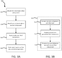
- FIG. 3A illustrates a method 500 of anodizing a bonded assembly, in accordance with various embodiments.
- Method 500 may comprise attaching a first electrode to a first component of a bonded assembly (step 502).
- method 500 may further comprise attaching a second electrode to a second component of the bonded assembly (step 504).
- step 502 of method 500 may comprise attaching a first electrode 700 to first component 602 of a bonded assembly 600.
- first electrode 700 may contact a first portion 618 of first component 602.
- Step 504 of method 500 may comprise attaching a second electrode 702 to second component 604 of bonded assembly 600.
- Step 504 may be performed before or after step 502. In various embodiments, step 502 and step 504 may be performed simultaneously.
- step 504 of method 500 may comprise contacting the second component of the bonded assembly with a first arm of the second electrode (step 510), disposing a second arm of the second electrode proximate the first component of the bonded assembly (step 512), and disposing an insulator between the second arm of the second electrode and the first component (step 514).
- step 510 may comprise contacting second component 604 of bonded assembly 600 with a first arm 704 of second electrode 702.
- Step 512 may comprise disposing a second arm 706 of second electrode 702 proximate first component 602 of bonded assembly 600.
- Step 514 may comprise disposing insulator 708 between second arm 706 of second electrode 702 and first component 602.
- insulator 708 may be attached or otherwise bonded to second arm 706. Insulator 708 may electrically isolate first component 602 from second electrode 702.
- Second electrode 702 may clamp against bonded assembly 600, such that first arm 704 and second arm 706 apply pressure in opposing directions against bonded assembly 600.
- steps 510, 512, and/or 514 may occur simultaneously.
- Second arm 706 may be disposed proximate a second portion 613 of first component 602 that is different from the first portion 618 of first component 602 to which first electrode 700 ( FIG. 2A ) is attached.
- bonded assembly 600 may comprise an assembled blade, and second arm 706 may be disposed proximate a suction side 613 of the assembled blade.
- method 500 may include applying a mask over a third component of the bonded assembly (step 506).
- step 506 of method 500 may comprise applying a mask 612 over third component 608 of bonded assembly 600.
- Mask 612 may comprise an electrically insulating material.
- mask 612 may comprise a tape, a wax, or other electrically insulating material configured to cover and protect third component 608 from the charged electrolytic solution, as described in further detail below.
- Mask 612 may be applied prior to or after attaching first electrode 700 and/or second electrode 702.
- third component 708 may not need to be masked, as third component 708 may comprise a material that is not affected by the charged electrolytic solution (e.g., third component 708 may comprise a non-metallic material) and/or the fixturing (i.e., the way in which first electrode 700 and second electrode 702 are attached) may alleviate a need for mask 612.
- third component 708 may comprise a material that is not affected by the charged electrolytic solution (e.g., third component 708 may comprise a non-metallic material) and/or the fixturing (i.e., the way in which first electrode 700 and second electrode 702 are attached) may alleviate a need for mask 612.
- method 500 may further comprise forming an oxide layer on one or more component(s) of the bonded assembly (step 508).
- step 508 may comprise forming separate and distinct oxide layers of similar chemistry on a first component and a second component of the bonded assembly.
- step 508 of method 500 may comprise forming separate and distinct oxide layers on first component 602 and second component 604 of bonded assembly 600.
- a first oxide layer may be formed on first component 602 and a second oxide layer may be formed on second component 604.
- the oxide layer on first component 602 and the oxide layer on second component 604 may be formed using a phosphoric acid anodization process, a chromic acid anodization process, a sulfuric acid anodization process, or other anodization process as known in the art.
- first component 602 and second component 604 may be cleaned, using, for example, acetone and then grit blasted, using, for example, a 240 mesh aluminum grit oxide grit.
- an alkali clean of first component 602 and second component 604 may be performed by, for example, disposing bonded assembly 600 in an agitated alkaline aqueous solution at about 150° F (65.6° C) for between 12 to 20 minutes. As used in the preceding sentence only, "about” means ⁇ 5° F.
- Bonded assembly 600 may then be rinsed and/or submerged in water (e.g., bonded assembly 600 may be submerged in water for between 1 to 5 minutes).
- First component 602 and second component 604 may then be power sprayed.
- first electrode 700 may be attached to first component 602 and second electrode 702 may be attached to second component 604.
- First component 602 and second component 604 may then be deoxidized by, for example, immersing bonded assembly 600 in an agitated aqueous lye solution at about 85° F (29.4° C). As used in the preceding sentence only, "about” means ⁇ 5° F.
- a direct current may be applied to the aqueous lye solution.
- a voltage of the direct current may be increased by 2 volts approximately every 10 seconds until 7.5 volts is attained.
- Bonded assembly 600 may remain in the deoxidizing aqueous lye solution for about 15 minutes. As used in the preceding sentence only, "about” means ⁇ 5 minutes.
- the above described deoxidation technique is merely an example.
- First component 602 and second component 604 may be deoxidized using an acid deoxidation process or any other suitable deoxidation technique known in the art.
- oxide layers may be formed on first component 602 and second component 604 by immersing bonded assembly 600 in an agitated electrolytic solution 620 at about 77° F (25° C).
- the electrolytic solution 620 may comprise phosphoric acid, chromic acid, sulfuric acid, or other suitably electrolytic solution.
- First electrode 700 and second electrode 702 may be coupled to a direct current power supply 710.
- First electrode 700 and second electrode 702 may be coupled to a positive direct current power supply terminal 712 of direct current power supply 710 via a wire or other electrical conduit 711.
- a cathode 716 (e.g., lead) may be electrically connected to a third electrode 718 and may be disposed in electrolytic solution 620 with bonded assembly 600.
- Third electrode 718 may be coupled to direct current power supply 710.
- Third electrode 718 may be coupled to a negative direct current power supply terminal 714 of direct current power supply 710, or to an electrical ground, via wire or other electrical conduit 720.
- first component 602 and second component 604 may be anodized for between 15 to 30 minutes. During the anodization, first component 602 and second component 604 may serve as anodes, which may cause a build-up of oxide on the surfaces of first component 602 and second component 604.
- first component 602 and second component 604 may exhibit a positive charge, which may attract and cause negatively charged ions to react at the components' metal surfaces, thereby creating an oxide layer on first component 602 and an oxide layer on second component 604.
- mask 612 may electrically insulate third component 608 from electrolytic solution 620
- adhesive 610 may electrically insulate third component 608 from first component 602 and first electrode 700.
- Masking third component 608 may protect the dissimilar metallic material of third component 608 from the anodization process.
- Masking third component 608 may also mitigate a risk of arcing between electrically isolated components of bonded assembly 600 and/or reduce charge inhomogeneity where dissimilar materials might be coupled by the anodized solution.
- bonded assembly 600 may be rinsed with water, dried in an oven at, for example, about 120° F (48.9° C) and then wrapped in paper. As used in the preceding sentence only, "about” means ⁇ 10° F.
- the steps of method 500 may be performed on assembled bonded assembly 600. Stated another way, the steps of method 500 may be carried out with second component 604 and third component 608 bonded to first component 602. Placing first electrode 700 in contact with first component 602 creates an electrical connection between first component 602 and power supply 710. Placing second electrode 702 in contact with second component 604 creates an electrical connection between second component 604 and power supply 710.
- first component 602 and second component 604 i.e., first electrode 700 and second electrode 702, respectively
- Method 500 may thus allow multiple components of bonded assembly 600 to be anodized simultaneously.
- bonded assembly 600 may comprise an assembled blade for use in fan section 22, compressor section 24, or turbine section 28 of engine 20 ( FIG. 1 ).
- First component 602 may comprise a blade body
- second component 604 may comprise a cover bonded to the blade body on a pressure side 614 of the assembled blade
- third component 608 may comprise a sheath bonded to the blade body at a leading edge 616 of the assembled blade.
- bonded assembly 600 may comprise an assembled blade, it should be understood that the anodization method disclosed herein may be used on any bonded assembly. Accordingly, bonded assembly 600 of the present disclosure is not limited to the specific geometry, size, shape, chemical make-up, and/or number of the components shown in the figures.
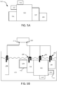
- Bonded assembly 100 may comprise a first component 102 and any number of subsequent components bonded to the first component 102 or bonded to a component bonded to the first component 102.
- component 104, component 106, component 110, and component 112 may be bonded to first component 102
- component 108 may be bonded to component 104.
- the first component 102 may be made from of a first metal
- each of the subsequent components e.g., components 104, 106, 108, and 110
- Each component of bonded assembly 100 may be electrically-coupled or electrically-isolated from the first component 102. Each component of bonded assembly 100 may be electrically-coupled or electrically-isolated from each of the other components of bonded assembly 100.
- the components of the bonded assembly 100 may be bonded to one another via adhesives (similar to adhesive 606 of FIG. 2B ), welds, or any other suitable bonding method.
- the bonded assembly 100 may also include any number of bonded non-metallic components.
- component 112 may be formed from a non-metallic material.
- one or more of the metallic components of the bonded assembly 100 may be anodized by attaching an electrode 200, electrically coupled to a positive power supply terminal 212, to each electrically-isolated component on which an oxide layer is desired. Stated differently, an oxide layer may be formed on any component of the bonded assembly 100 that is electrically coupled to an electrode 200. After attaching the electrode(s) 200 to the one or more components of the bonded assembly 100, the bonded assembly 100 may be disposed in an electrolytic solution 230 along with a cathode 216 that is electrically coupled to a negative power supply terminal 214.
- a current may be passed through the electrolytic solution 230 and an oxide layer may be formed on each component (e.g., components 102, 104, and 106) of bonded assembly 100 that is electrically coupled to positive power supply terminal 212.
- a mask 114 similar to mask 612 in FIG. 2B , may be applied over any electrically isolated component (e.g., components 108 and 110) of the bonded assembly 100 on which an oxide layer is not desired.
- Anodizing one or more components of bonded assembly 100 without first disassembling the bonded assembly 100, may simplify the anodization and/or repair processes, which tends to lead to decreased manufacture and/or repair times and reduced costs.
- references to "one embodiment,” “an embodiment,” “an example embodiment,” etc. indicate that the embodiment described may include a particular feature, structure, or characteristic, but every embodiment may not necessarily include the particular feature, structure, or characteristic. Moreover, such phrases are not necessarily referring to the same embodiment. Further, when a particular feature, structure, or characteristic is described in connection with an embodiment, it is submitted that it may be within the knowledge of one skilled in the art to affect such feature, structure, or characteristic in connection with other embodiments whether or not explicitly described. After reading the description, it will be apparent to one skilled in the relevant art(s) how to implement the disclosure in alternative embodiments.
Landscapes
- Chemical & Material Sciences (AREA)
- Engineering & Computer Science (AREA)
- Materials Engineering (AREA)
- Organic Chemistry (AREA)
- Chemical Kinetics & Catalysis (AREA)
- Electrochemistry (AREA)
- Metallurgy (AREA)
- General Engineering & Computer Science (AREA)
- Mechanical Engineering (AREA)
- Transportation (AREA)
- Manufacturing & Machinery (AREA)
- Aviation & Aerospace Engineering (AREA)
- Combustion & Propulsion (AREA)
- Inorganic Chemistry (AREA)
- Structures Of Non-Positive Displacement Pumps (AREA)
- Formation Of Insulating Films (AREA)
- Other Surface Treatments For Metallic Materials (AREA)
Abstract
Description
- The present disclosure relates generally to repairing aircraft parts, and more specifically, to anodizing bonded assemblies.
- Anodization may be used to create an oxide layer or film on the surface of a metal. The oxide layer may provide corrosion resistance and may promote bonding of adhesives or other coatings which may be applied to the metal's surface. For example, an aluminum oxide layer may be formed on an aluminum component to increase the bond strength of adhesives and/or coatings that may be subsequently applied to the aluminum component. In addition, for various reasons, including but not limited to repair, it may be desirable to anodize some or all components of a bonded assembly consisting of similar and/or dissimilar bonded metal components. Bonded assemblies may consist of galvanically-similar and/or galvanically-dissimilar metal components that may be electrically coupled and/or electrically isolated from one another. Current methods for anodizing metal components of a bonded assembly tend to include disassembling the components and anodizing components separately.
- A method of anodizing a bonded assembly is disclosed, in accordance with various embodiments. A method of anodizing a bonded assembly may comprise attaching a first electrode to a first component of the bonded assembly. The bonded assembly may comprise the first component and a second component bonded to the first component. The second component may be electrically isolated from the first component. The method may further comprise attaching a second electrode to the second component of the bonded assembly, and forming a first oxide layer on the first component and a second oxide layer on the second component.
- In various embodiments, forming the first oxide layer on the first component and the second oxide layer on the second component may comprise disposing the bonded assembly in an electrolytic solution, coupling the first electrode and the second electrode to a positive power supply terminal, and passing a current through the electrolytic solution. Attaching the second electrode to the second component comprises contacting the second component with a first arm of the second electrode, and disposing an insulator between a second arm of the second electrode and the first component.
- In various embodiments, the bonded assembly may further comprise a third component bonded to at least one of the first component or the second component. The method may further comprise applying an insulating mask over the third component. In various embodiments, at least one of the first component or the second component may comprise a first metal, and the third component may comprise a second metal galvanically-dissimilar to the first metal. The first metal may comprise at least one of aluminum or aluminum alloy, and the second metal may comprise at least one of titanium or titanium alloy. In various embodiments, the assembled body may comprise an assembled blade.
- A method of anodizing components of a bonded assembly of a turbine engine is disclosed, in accordance with various embodiments. The method may comprise attaching a first electrode to a first component of the bonded assembly, and forming a first oxide layer on the first component of the bonded assembly. The bonded assembly may comprise the first component and a second component bonded to the first component.
- In various embodiments, the method may further comprise attaching a second electrode to the second component of the bonded assembly, and forming a second oxide layer over the second component. An adhesive comprising an electrically insulating material may be disposed between the first component and the second component. In various embodiments, forming the first oxide layer may comprise disposing the bonded assembly in an electrolytic solution, coupling the first electrode to a positive power supply terminal, and passing a current through the electrolytic solution. The electrolytic solution may comprise at least one of phosphoric acid, chromic acid, or sulfuric acid.
- In various embodiments, the bonded assembly may further comprise a third component bonded to at least one of the first component or the second component. The method may further comprise applying an insulating mask over the third component. At least one of the first component or the second component may comprise a first metal, and the third component may comprise a second metal galvanically-dissimilar to the first metal.
- A method of anodizing an assembled blade is disclosed, in accordance with various embodiments. The method may comprise attaching a first electrode to a blade body of the assembled blade. The assembled blade may comprise the blade body, a cover bonded to the blade body, and a sheath bonded to a leading edge of the blade body. The method may further comprise attaching a second electrode to the cover, disposing the assembled blade in an electrolytic solution, and passing a current through the electrolytic solution. The first electrode and the second electrode may be coupled to a positive power supply terminal.
- In various embodiments, the method may further comprise applying an insulating mask over the sheath. The blade body and the cover may comprise a first metal, and the sheath may comprise a second metal galvanically-dissimilar to the first metal. Attaching the second electrode to the cover may comprise contacting the cover with a first arm of the second electrode, disposing a second arm of the second electrode proximate a suction side of the blade body, and disposing an insulator between the second arm of the second electrode and the suction side of the blade body.
- The foregoing features and elements may be combined in various combinations without exclusivity, unless expressly indicated herein otherwise. These features and elements as well as the operation of the disclosed embodiments will become more apparent in light of the following description and accompanying drawings.
- The subject matter of the present disclosure is particularly pointed out and distinctly claimed in the concluding portion of the specification. A more complete understanding of the present disclosure, however, may best be obtained by referring to the detailed description and claims when considered in connection with the drawing figures, wherein like numerals denote like elements.
-
FIG. 1 illustrates a gas turbine engine, in accordance with various embodiments; -
FIGs. 2A and 2B illustrate a perspective view and a plan view, respectively, of electrodes attached to a bonded assembly, in accordance with various embodiments; -
FIGs. 3A and 3B illustrate a method of anodizing a bonded assembly, in accordance with various embodiments; -
FIG. 4 illustrates anodization of a bonded assembly in an electrolytic solution, in accordance with various embodiments; and -
FIG. 5A illustrates a bonded assembly, in accordance with various embodiments; and -
FIG. 5B illustrates anodization of the bonded assembly ofFIG. 5A , in accordance with various embodiments. - The detailed description of embodiments herein makes reference to the accompanying drawings, which show embodiments by way of illustration. While these embodiments are described in sufficient detail to enable those skilled in the art to practice the inventions, it should be understood that other embodiments may be realized and that logical and mechanical changes may be made without departing from the scope of the inventions. Thus, the detailed description herein is presented for purposes of illustration only and not for limitation. For example, any reference to singular includes plural embodiments, and any reference to more than one component or step may include a singular embodiment or step. Also, any reference to attached, fixed, connected or the like may include permanent, removable, temporary, partial, full and/or any other possible attachment option. Additionally, any reference to without contact (or similar phrases) may also include reduced contact or minimal contact. Surface cross hatching lines may be used throughout the figures to denote different parts but not necessarily to denote the same or different materials.
- Throughout the present disclosure, like reference numbers denote like elements. Accordingly, elements with like element numbering may be shown in the figures, but may not be necessarily be repeated herein for the sake of clarity. As used herein, "distal" refers to the direction outward, or generally, away from a reference component. As used herein, "proximal" and/or "proximate" refers to a direction inward, or generally, towards the reference component.
- In various embodiments of the present disclosure, methods for anodizing a bonded assembly are described. A bonded assembly may include a plurality of bonded components that are electrically isolated from one another and/or are comprised of galvanically different materials. The described methods may allow one or more components of the bonded assembly to be anodized without having to first disassemble the bonded assembly.
- With reference to
FIG. 1 , agas turbine engine 20 is provided.Gas turbine engine 20 may be a two-spool turbofan that generally incorporates afan section 22, acompressor section 24, acombustor section 26 and aturbine section 28. Alternative engines may include, for example, an augmentor section among other systems or features. In operation,fan section 22 can drive a fluid (e.g., air) along a bypass flow-path B whilecompressor section 24 can drive fluid along a core flow-path C for compression and communication intocombustor section 26 then expansion throughturbine section 28. Although depicted as a turbofangas turbine engine 20 herein, it should be understood that the concepts described herein are not limited to use with turbofans as the teachings may be applied to other types of turbine engines including three-spool architectures. -
Gas turbine engine 20 may generally comprise alow speed spool 30 and ahigh speed spool 32 mounted for rotation about an engine central longitudinal axis A-A' relative to an enginestatic structure 36 or engine case viaseveral bearing systems 38, 38-1, and 38-2. Engine central longitudinal axis A-A' is oriented along the z-axis on the provided xyz axis. It should be understood that various bearingsystems 38 at various locations may alternatively or additionally be provided, including for example, bearingsystem 38, bearing system 38-1, and bearing system 38-2. -
Low speed spool 30 may generally comprise aninner shaft 40 that interconnects afan 42, alow pressure compressor 44 and alow pressure turbine 46.Inner shaft 40 may be connected to fan 42 through a gearedarchitecture 48 that can drivefan 42 at a lower speed thanlow speed spool 30.Geared architecture 48 may comprise agear assembly 60 enclosed within agear housing 62.Gear assembly 60 couplesinner shaft 40 to a rotating fan structure.High speed spool 32 may comprise anouter shaft 50 that interconnects ahigh pressure compressor 52 andhigh pressure turbine 54. Acombustor 56 may be located betweenhigh pressure compressor 52 andhigh pressure turbine 54. Amid-turbine frame 57 of enginestatic structure 36 may be located generally betweenhigh pressure turbine 54 andlow pressure turbine 46.Mid-turbine frame 57 may support one ormore bearing systems 38 inturbine section 28.Inner shaft 40 andouter shaft 50 may be concentric and rotate via bearingsystems 38 about the engine central longitudinal axis A-A', which is collinear with their longitudinal axes. As used herein, a "high pressure" compressor or turbine experiences a higher pressure than a corresponding "low pressure" compressor or turbine. - The core airflow C may be compressed by
low pressure compressor 44 thenhigh pressure compressor 52, mixed and burned with fuel incombustor 56, then expanded overhigh pressure turbine 54 andlow pressure turbine 46.Turbines low speed spool 30 andhigh speed spool 32 in response to the expansion. - The
fan section 22, thecompressor section 24, and theturbine section 28 may each comprise rotor systems including blade assemblies having one or more sets of rotating blades, which may rotate about engine central longitudinal axis A-A'. - With reference to
FIGs. 2A and 2B , a bondedassembly 600 is illustrated, in accordance with various embodiments.Bonded assembly 600 may include afirst component 602 and asecond component 604 bonded tofirst component 602.Second component 604 may be bonded tofirst component 602 using an adhesive 606. In various embodiments, adhesive 606 may comprise, for example, one or more epoxies, bismalemides, cyanate esters, polyurethanes, silicones, or polyimides, and may be a supported or unsupported film and/or paste. Adhesive 606 may comprise an electrically insulating material. Adhesive 606 may thus electrically isolatefirst component 602 fromsecond component 604. -
First component 602 andsecond component 604 may each be fabricated from a metallic material, such as a metal and/or a metal alloy. In various embodiments,first component 602 andsecond component 604 may comprise a same or similar material. For example,first component 602 andsecond component 604 may each comprise aluminum or aluminum alloy. - In various embodiments, bonded
assembly 600 may further comprise athird component 608 bonded tofirst component 602.Third component 608 may be bonded tofirst component 602 using an adhesive 610. In various embodiments, adhesive 610 may comprise, for example, one or more epoxies, bismalemides, cyanate esters, polyurethanes, silicones, or polyimides, and may be a supported or unsupported film and/or paste. Adhesive 610 may comprise an electrically insulating material. Adhesive 610 may thus electrically isolatefirst component 602 fromthird component 608. In various embodiments,third component 608 may be bonded tosecond component 604. -
Third component 608 may be fabricated from a metallic material, such as a metal and/or a metal alloy. In various embodiments,third component 608 may be made of titanium, nickel, or steel (including alloys of any). In various embodiments,first component 602 andsecond component 604 may be made from a first metallic material, andthird component 608 may be made from a second metallic material that is galvanically-dissimilar to the first metallic material. In various embodiments,first component 602 andsecond component 604 may comprise aluminum or aluminum alloy, andthird component 608 may comprise titanium or titanium alloy. - It may be desirable to anodize the metallic surfaces of
first component 602 andsecond component 604. For example, the metallic surfaces offirst component 602 andsecond component 604 may be anodized to promote bonding and/or adhesion of various coatings, primers, and/or adhesives that may be applied tofirst component 602 and/orsecond component 604. Stated differently, an oxide layer may be formed on the metallic surfaces offirst component 602 and on the metallic surfaces ofsecond component 604. The oxide layer may form chemical bonds with coatings, primers, and/or adhesives applied tofirst component 602 and/orsecond component 604, thereby increasing an adhesion strength of the applied materials. In addition, the oxide layer may promote mechanical locking, as the microroughness and porous structure of the oxide layer tends to increase mechanical interlocking with primers subsequently applied tofirst component 602 and/orsecond component 604. -
FIG. 3A illustrates amethod 500 of anodizing a bonded assembly, in accordance with various embodiments.Method 500 may comprise attaching a first electrode to a first component of a bonded assembly (step 502). In various embodiments,method 500 may further comprise attaching a second electrode to a second component of the bonded assembly (step 504). - With combined reference to
FIG. 2A andFIG. 3A , step 502 ofmethod 500 may comprise attaching afirst electrode 700 tofirst component 602 of a bondedassembly 600. In various embodiments,first electrode 700 may contact afirst portion 618 offirst component 602. Step 504 ofmethod 500 may comprise attaching asecond electrode 702 tosecond component 604 of bondedassembly 600. Step 504 may be performed before or afterstep 502. In various embodiments,step 502 and step 504 may be performed simultaneously. - With reference to
FIG. 3B , in various embodiments, step 504 ofmethod 500 may comprise contacting the second component of the bonded assembly with a first arm of the second electrode (step 510), disposing a second arm of the second electrode proximate the first component of the bonded assembly (step 512), and disposing an insulator between the second arm of the second electrode and the first component (step 514). - With combined reference to
FIG. 2B andFIG. 3B , in various embodiments,step 510 may comprise contactingsecond component 604 of bondedassembly 600 with afirst arm 704 ofsecond electrode 702. Step 512 may comprise disposing asecond arm 706 ofsecond electrode 702 proximatefirst component 602 of bondedassembly 600. Step 514 may comprise disposinginsulator 708 betweensecond arm 706 ofsecond electrode 702 andfirst component 602. In various embodiments,insulator 708 may be attached or otherwise bonded tosecond arm 706.Insulator 708 may electrically isolatefirst component 602 fromsecond electrode 702.Second electrode 702 may clamp against bondedassembly 600, such thatfirst arm 704 andsecond arm 706 apply pressure in opposing directions against bondedassembly 600. In various embodiments,steps Second arm 706 may be disposed proximate asecond portion 613 offirst component 602 that is different from thefirst portion 618 offirst component 602 to which first electrode 700 (FIG. 2A ) is attached. In various embodiments, bondedassembly 600 may comprise an assembled blade, andsecond arm 706 may be disposed proximate asuction side 613 of the assembled blade. - Returning to
FIG. 3A , in various embodiments,method 500 may include applying a mask over a third component of the bonded assembly (step 506). With combined reference toFIG. 2B andFIG. 3A , step 506 ofmethod 500 may comprise applying amask 612 overthird component 608 of bondedassembly 600.Mask 612 may comprise an electrically insulating material. In various embodiments,mask 612 may comprise a tape, a wax, or other electrically insulating material configured to cover and protectthird component 608 from the charged electrolytic solution, as described in further detail below.Mask 612 may be applied prior to or after attachingfirst electrode 700 and/orsecond electrode 702. In various embodiments,third component 708 may not need to be masked, asthird component 708 may comprise a material that is not affected by the charged electrolytic solution (e.g.,third component 708 may comprise a non-metallic material) and/or the fixturing (i.e., the way in whichfirst electrode 700 andsecond electrode 702 are attached) may alleviate a need formask 612. - Returning to
FIG. 3A ,method 500 may further comprise forming an oxide layer on one or more component(s) of the bonded assembly (step 508). In various embodiments,step 508 may comprise forming separate and distinct oxide layers of similar chemistry on a first component and a second component of the bonded assembly. - With combined reference to
FIG. 2A andFIG. 3A , step 508 ofmethod 500 may comprise forming separate and distinct oxide layers onfirst component 602 andsecond component 604 of bondedassembly 600. For example, a first oxide layer may be formed onfirst component 602 and a second oxide layer may be formed onsecond component 604. The oxide layer onfirst component 602 and the oxide layer onsecond component 604 may be formed using a phosphoric acid anodization process, a chromic acid anodization process, a sulfuric acid anodization process, or other anodization process as known in the art. For example, in various embodiments, prior to attachingfirst electrode 700 andsecond electrode 702,first component 602 andsecond component 604 may be cleaned, using, for example, acetone and then grit blasted, using, for example, a 240 mesh aluminum grit oxide grit. Alternatively, or in addition, an alkali clean offirst component 602 andsecond component 604 may be performed by, for example, disposing bondedassembly 600 in an agitated alkaline aqueous solution at about 150° F (65.6° C) for between 12 to 20 minutes. As used in the preceding sentence only, "about" means ±5°F. Bonded assembly 600 may then be rinsed and/or submerged in water (e.g., bondedassembly 600 may be submerged in water for between 1 to 5 minutes).First component 602 andsecond component 604 may then be power sprayed. After the power spray,first electrode 700 may be attached tofirst component 602 andsecond electrode 702 may be attached tosecond component 604.First component 602 andsecond component 604 may then be deoxidized by, for example, immersing bondedassembly 600 in an agitated aqueous lye solution at about 85° F (29.4° C). As used in the preceding sentence only, "about" means ±5° F. A direct current may be applied to the aqueous lye solution. A voltage of the direct current may be increased by 2 volts approximately every 10 seconds until 7.5 volts is attained.Bonded assembly 600 may remain in the deoxidizing aqueous lye solution for about 15 minutes. As used in the preceding sentence only, "about" means ±5 minutes. The above described deoxidation technique is merely an example.First component 602 andsecond component 604 may be deoxidized using an acid deoxidation process or any other suitable deoxidation technique known in the art. - Referring to
FIG. 4 , after deoxidizing, oxide layers may be formed onfirst component 602 andsecond component 604 by immersing bondedassembly 600 in an agitatedelectrolytic solution 620 at about 77° F (25° C). As used in the preceding sentence only, "about" means ±5° F. Theelectrolytic solution 620 may comprise phosphoric acid, chromic acid, sulfuric acid, or other suitably electrolytic solution.First electrode 700 andsecond electrode 702 may be coupled to a directcurrent power supply 710.First electrode 700 andsecond electrode 702 may be coupled to a positive direct currentpower supply terminal 712 of directcurrent power supply 710 via a wire or otherelectrical conduit 711. A cathode 716 (e.g., lead) may be electrically connected to athird electrode 718 and may be disposed inelectrolytic solution 620 with bondedassembly 600.Third electrode 718 may be coupled to directcurrent power supply 710.Third electrode 718 may be coupled to a negative direct currentpower supply terminal 714 of directcurrent power supply 710, or to an electrical ground, via wire or otherelectrical conduit 720. - After connecting the first, second, and third electrodes to direct
current power supply 710, the direct current power supply is turned on and a direct current is passed throughelectrolytic solution 620. The voltage of the direct current may be increased by 2 volts approximately every 10 seconds until 15 volts is attained.First component 602 andsecond component 604 may be anodized for between 15 to 30 minutes. During the anodization,first component 602 andsecond component 604 may serve as anodes, which may cause a build-up of oxide on the surfaces offirst component 602 andsecond component 604. Stated another way, during the anodization,first component 602 andsecond component 604 may exhibit a positive charge, which may attract and cause negatively charged ions to react at the components' metal surfaces, thereby creating an oxide layer onfirst component 602 and an oxide layer onsecond component 604. With combined reference toFIG. 2B andFIG. 4 , during the anodization,mask 612 may electrically insulatethird component 608 fromelectrolytic solution 620, and adhesive 610 may electrically insulatethird component 608 fromfirst component 602 andfirst electrode 700. Maskingthird component 608 may protect the dissimilar metallic material ofthird component 608 from the anodization process. Maskingthird component 608 may also mitigate a risk of arcing between electrically isolated components of bondedassembly 600 and/or reduce charge inhomogeneity where dissimilar materials might be coupled by the anodized solution. - After the anodization, bonded
assembly 600 may be rinsed with water, dried in an oven at, for example, about 120° F (48.9° C) and then wrapped in paper. As used in the preceding sentence only, "about" means ±10° F. - The steps of
method 500 may be performed on assembled bondedassembly 600. Stated another way, the steps ofmethod 500 may be carried out withsecond component 604 andthird component 608 bonded tofirst component 602. Placingfirst electrode 700 in contact withfirst component 602 creates an electrical connection betweenfirst component 602 andpower supply 710. Placingsecond electrode 702 in contact withsecond component 604 creates an electrical connection betweensecond component 604 andpower supply 710. Having a dedicated electrode for each of thefirst component 602 and second component 604 (i.e.,first electrode 700 andsecond electrode 702, respectively) connected to the positive direct current power supply allowsfirst component 602 andsecond component 604, which are electrically isolated from one another by adhesive 606, to both serve as anodes in the electrolytic solution, and to be anodized while remaining bonded together.Method 500 may thus allow multiple components of bondedassembly 600 to be anodized simultaneously. - In various embodiments, bonded
assembly 600 may comprise an assembled blade for use infan section 22,compressor section 24, orturbine section 28 of engine 20 (FIG. 1 ).First component 602 may comprise a blade body,second component 604 may comprise a cover bonded to the blade body on apressure side 614 of the assembled blade, andthird component 608 may comprise a sheath bonded to the blade body at aleading edge 616 of the assembled blade. - While bonded
assembly 600 may comprise an assembled blade, it should be understood that the anodization method disclosed herein may be used on any bonded assembly. Accordingly, bondedassembly 600 of the present disclosure is not limited to the specific geometry, size, shape, chemical make-up, and/or number of the components shown in the figures. - Referring to
FIG. 5A , a bondedassembly 100 is shown, according to various embodiments.Bonded assembly 100 may comprise afirst component 102 and any number of subsequent components bonded to thefirst component 102 or bonded to a component bonded to thefirst component 102. For example,component 104,component 106,component 110, andcomponent 112 may be bonded tofirst component 102, andcomponent 108 may be bonded tocomponent 104. Thefirst component 102 may be made from of a first metal, and each of the subsequent components (e.g.,components first component 102 or a galvanically-dissimilar metal. Each component of bondedassembly 100 may be electrically-coupled or electrically-isolated from thefirst component 102. Each component of bondedassembly 100 may be electrically-coupled or electrically-isolated from each of the other components of bondedassembly 100. The components of the bondedassembly 100 may be bonded to one another via adhesives (similar to adhesive 606 ofFIG. 2B ), welds, or any other suitable bonding method. The bondedassembly 100 may also include any number of bonded non-metallic components. For example,component 112 may be formed from a non-metallic material. - With reference to
FIG. 5B , one or more of the metallic components of the bondedassembly 100 may be anodized by attaching anelectrode 200, electrically coupled to a positivepower supply terminal 212, to each electrically-isolated component on which an oxide layer is desired. Stated differently, an oxide layer may be formed on any component of the bondedassembly 100 that is electrically coupled to anelectrode 200. After attaching the electrode(s) 200 to the one or more components of the bondedassembly 100, the bondedassembly 100 may be disposed in anelectrolytic solution 230 along with acathode 216 that is electrically coupled to a negativepower supply terminal 214. A current may be passed through theelectrolytic solution 230 and an oxide layer may be formed on each component (e.g.,components assembly 100 that is electrically coupled to positivepower supply terminal 212. Amask 114, similar tomask 612 inFIG. 2B , may be applied over any electrically isolated component (e.g.,components 108 and 110) of the bondedassembly 100 on which an oxide layer is not desired. Anodizing one or more components of bondedassembly 100, without first disassembling the bondedassembly 100, may simplify the anodization and/or repair processes, which tends to lead to decreased manufacture and/or repair times and reduced costs. - Benefits, other advantages, and solutions to problems have been described herein with regard to specific embodiments. Furthermore, the connecting lines shown in the various figures contained herein are intended to represent exemplary functional relationships and/or physical couplings between the various elements. It should be noted that many alternative or additional functional relationships or physical connections may be present in a practical system. However, the benefits, advantages, solutions to problems, and any elements that may cause any benefit, advantage, or solution to occur or become more pronounced are not to be construed as critical, required, or essential features or elements of the inventions. The scope of the inventions is accordingly to be limited by nothing other than the appended claims, in which reference to an element in the singular is not intended to mean "one and only one" unless explicitly so stated, but rather "one or more." Moreover, where a phrase similar to "at least one of A, B, or C" is used in the claims, it is intended that the phrase be interpreted to mean that A alone may be present in an embodiment, B alone may be present in an embodiment, C alone may be present in an embodiment, or that any combination of the elements A, B and C may be present in a single embodiment; for example, A and B, A and C, B and C, or A and B and C.
- Systems, methods and apparatus are provided herein. In the detailed description herein, references to "one embodiment," "an embodiment," "an example embodiment," etc., indicate that the embodiment described may include a particular feature, structure, or characteristic, but every embodiment may not necessarily include the particular feature, structure, or characteristic. Moreover, such phrases are not necessarily referring to the same embodiment. Further, when a particular feature, structure, or characteristic is described in connection with an embodiment, it is submitted that it may be within the knowledge of one skilled in the art to affect such feature, structure, or characteristic in connection with other embodiments whether or not explicitly described. After reading the description, it will be apparent to one skilled in the relevant art(s) how to implement the disclosure in alternative embodiments.
- Furthermore, no element, component, or method step in the present disclosure is intended to be dedicated to the public regardless of whether the element, component, or method step is explicitly recited in the claims. No claim element herein is to be construed under the provisions of 35 U.S.C. 112(f), unless the element is expressly recited using the phrase "means for." As used herein, the terms "comprises," "comprising," or any other variation thereof, are intended to cover a non-exclusive inclusion, such that a process, method, article, or apparatus that comprises a list of elements does not include only those elements but may include other elements not expressly listed or inherent to such process, method, article, or apparatus.
Claims (15)
- A method of anodizing a bonded assembly, comprising:attaching a first electrode to a first component of the bonded assembly, the bonded assembly comprising:the first component, anda second component bonded to the first component, wherein the second component is electrically isolated from the first component;attaching a second electrode to the second component of the bonded assembly; andforming a first oxide layer on the first component and a second oxide layer on the second component.
- The method of claim 1, wherein the forming the first oxide layer on the first component and the second oxide layer on the second component comprises:disposing the bonded assembly in an electrolytic solution;coupling the first electrode and the second electrode to a positive power supply terminal; andpassing a current through the electrolytic solution.
- The method of claim 1 or 2, wherein the bonded assembly further comprises a third component bonded to at least one of the first component or the second component.
- The method of claim 3, further comprising applying an insulating mask over the third component.
- The method of claim 3 or 4, wherein at least one of the first component or the second component comprises a first metal, and wherein the third component comprises a second metal galvanically-dissimilar to the first metal,
wherein, optionally, the first metal comprises at least one of aluminum or aluminum alloy, and wherein the second metal comprises at least one of titanium or titanium alloy. - The method of any preceding claim, wherein the assembled body comprises an assembled blade.
- The method of any preceding claim, wherein attaching the second electrode to the second component comprises contacting the second component with a first arm of the second electrode, and disposing an insulator between a second arm of the second electrode and the first component.
- A method of anodizing components of a bonded assembly of a turbine engine, comprising:attaching a first electrode to a first component of the bonded assembly, the bonded assembly comprising:the first component, anda second component bonded to the first component; andforming a first oxide layer on the first component of the bonded assembly.
- The method of claim 8, further comprising:attaching a second electrode to the second component of the bonded assembly; andforming a second oxide layer over the second component.
- The method of claim 9, wherein an adhesive comprising an electrically insulating material is disposed between the first component and the second component.
- The method of any of claims 8 to 10, wherein the forming the first oxide layer comprises:disposing the bonded assembly in an electrolytic solution;coupling the first electrode to a positive power supply terminal; and passing a current through the electrolytic solution,wherein, optionally, the electrolytic solution comprises at least one of phosphoric acid, chromic acid, or sulfuric acid.
- The method of any of claims 8 to 11, wherein the bonded assembly further comprises a third component bonded to at least one of the first component or the second component,
optionally further comprising applying an insulating mask over the third component. - The method of claim 12, wherein at least one of the first component or the second component comprises a first metal, and wherein the third component comprises a second metal galvanically-dissimilar to the first metal.
- A method of anodizing an assembled blade, comprising:attaching a first electrode to a blade body of the assembled blade, the assembled blade comprising:the blade body,a cover bonded to the blade body, anda sheath bonded to a leading edge of the blade body;attaching a second electrode to the cover;disposing the assembled blade in an a electrolytic solution; andpassing a current through the electrolytic solution, wherein the first electrode and the second electrode are coupled to a positive power supply terminal.
- The method of claim 14, further comprising applying an insulating mask over the sheath, and/or
wherein, optionally, the blade body and the cover comprise a first metal, and the sheath comprises a second metal galvanically-dissimilar to the first metal, and/or
wherein, optionally, the attaching the second electrode to the cover comprises:contacting the cover with a first arm of the second electrode;disposing a second arm of the second electrode proximate a suction side of the blade body; anddisposing an insulator between the second arm of the second electrode and the suction side of the blade body.
Applications Claiming Priority (1)
| Application Number | Priority Date | Filing Date | Title |
|---|---|---|---|
| US15/656,571 US10458035B2 (en) | 2017-07-21 | 2017-07-21 | Anodization of bonded assembly |
Publications (3)
| Publication Number | Publication Date |
|---|---|
| EP3431636A2 true EP3431636A2 (en) | 2019-01-23 |
| EP3431636A3 EP3431636A3 (en) | 2019-03-06 |
| EP3431636B1 EP3431636B1 (en) | 2020-04-15 |
Family
ID=62873211
Family Applications (1)
| Application Number | Title | Priority Date | Filing Date |
|---|---|---|---|
| EP18181625.7A Active EP3431636B1 (en) | 2017-07-21 | 2018-07-04 | Anodization of bonded assembly |
Country Status (2)
| Country | Link |
|---|---|
| US (1) | US10458035B2 (en) |
| EP (1) | EP3431636B1 (en) |
Families Citing this family (1)
| Publication number | Priority date | Publication date | Assignee | Title |
|---|---|---|---|---|
| TW202600678A (en) * | 2024-02-05 | 2026-01-01 | 德商漢高股份有限及兩合公司 | Methods to maintain and/or improve adhesion after anodizing aluminum or titanium substrates bonded together with curable compositions |
Family Cites Families (13)
| Publication number | Priority date | Publication date | Assignee | Title |
|---|---|---|---|---|
| US3349014A (en) | 1964-08-28 | 1967-10-24 | Mc Donnell Douglas Corp | Method and composition for the treatment of an aluminum surface |
| US3619385A (en) * | 1968-02-05 | 1971-11-09 | Nadezhda Vasilievna Rjumshina | Process for manufacturing an article with a polychrome picture imposed on the surface thereof |
| CH542935A (en) | 1970-12-09 | 1973-10-15 | Rapena Patent & Verwaltungs Ag | Process for the galvanic treatment of metallic profile bodies and profile bodies, treated according to the process |
| JPS5934238B2 (en) | 1981-10-29 | 1984-08-21 | 橋本フオ−ミング工業株式会社 | Surface treatment method for metal members having joints |
| US4988414A (en) | 1988-05-02 | 1991-01-29 | The Boeing Company | In-situ surface treatment containment apparatus and method |
| US20100155251A1 (en) | 2008-12-23 | 2010-06-24 | United Technologies Corporation | Hard anodize of cold spray aluminum layer |
| US20100159273A1 (en) | 2008-12-24 | 2010-06-24 | John Benjamin Filson | Method and Apparatus for Forming a Layered Metal Structure with an Anodized Surface |
| US20130236712A1 (en) | 2012-03-06 | 2013-09-12 | Alcoa Inc. | Metal laminates and methods thereof |
| US20140010663A1 (en) * | 2012-06-28 | 2014-01-09 | Joseph Parkos, JR. | Gas turbine engine fan blade tip treatment |
| EP2900923B1 (en) * | 2012-09-25 | 2019-12-25 | United Technologies Corporation | Airfoil array with vanes that differ in geometry according to geometry classes |
| EP2971531B1 (en) | 2013-03-15 | 2020-03-04 | United Technologies Corporation | Blades and manufacture methods |
| US10730151B2 (en) * | 2014-01-03 | 2020-08-04 | Raytheon Technologies Corporation | Systems and methods for airfoil assembly |
| US20160017510A1 (en) * | 2014-07-21 | 2016-01-21 | United Technologies Corporation | Multifunctional anodized layer |
-
2017
- 2017-07-21 US US15/656,571 patent/US10458035B2/en active Active
-
2018
- 2018-07-04 EP EP18181625.7A patent/EP3431636B1/en active Active
Non-Patent Citations (1)
| Title |
|---|
| None |
Also Published As
| Publication number | Publication date |
|---|---|
| US20190024255A1 (en) | 2019-01-24 |
| EP3431636A3 (en) | 2019-03-06 |
| EP3431636B1 (en) | 2020-04-15 |
| US10458035B2 (en) | 2019-10-29 |
Similar Documents
| Publication | Publication Date | Title |
|---|---|---|
| US20140010663A1 (en) | Gas turbine engine fan blade tip treatment | |
| US8449784B2 (en) | Method for securing a sheath to a blade | |
| JP2828168B2 (en) | Method of forming composite structure and composite | |
| JP5367661B2 (en) | Connection structure | |
| US9920444B2 (en) | Co-bonded electroformed abrasion strip | |
| EP3287597B1 (en) | Air foil with galvanic protection | |
| EP3431636B1 (en) | Anodization of bonded assembly | |
| US9926793B2 (en) | Blades and manufacture methods | |
| CN115255804A (en) | Rapid repairing method for aircraft fuel tank skin hole fault | |
| CN102347673A (en) | Method for assembling and fastening dual permanent magnet power frequency brushless synchronous generator rotor magnetic shoe | |
| US10612400B2 (en) | Composite fan platform lug reinforcement | |
| CN115552117A (en) | Windmill blade, windmill, and method for repairing windmill blade | |
| CN102169978B (en) | Nickel coated aluminum battery cell tab | |
| EP3406759A1 (en) | Green repair of oxidation and corrosion resistant coatings | |
| WO2015040951A1 (en) | Electroconductive structure for jet engine | |
| JP2697469B2 (en) | Gas turbine blades, vanes and combustor liners and manufacturing method | |
| US11286776B2 (en) | Method for separation of a metallic element glued to an element made of a composite material | |
| US9422821B2 (en) | Selective coating removal or masking for ground path | |
| US12083625B2 (en) | Laser surface treatment on stainless steel and nickel alloys for adhesive bonding | |
| EP3190162B1 (en) | Systems and methods for bonding of dissimilar substrates | |
| EP3060361A1 (en) | Blade with protective layer | |
| EP3336223B1 (en) | Fan blade with protective cladding and method of making | |
| EP2878407A2 (en) | Process for fabricating a tool used in electrochemical maching and tool made by the process | |
| EP3748125A1 (en) | Methods for repairing a multi-layer coated component | |
| US20250376987A1 (en) | In-situ electroplated sheath for composite fan blade |
Legal Events
| Date | Code | Title | Description |
|---|---|---|---|
| PUAI | Public reference made under article 153(3) epc to a published international application that has entered the european phase |
Free format text: ORIGINAL CODE: 0009012 |
|
| STAA | Information on the status of an ep patent application or granted ep patent |
Free format text: STATUS: THE APPLICATION HAS BEEN PUBLISHED |
|
| AK | Designated contracting states |
Kind code of ref document: A2 Designated state(s): AL AT BE BG CH CY CZ DE DK EE ES FI FR GB GR HR HU IE IS IT LI LT LU LV MC MK MT NL NO PL PT RO RS SE SI SK SM TR |
|
| AX | Request for extension of the european patent |
Extension state: BA ME |
|
| PUAL | Search report despatched |
Free format text: ORIGINAL CODE: 0009013 |
|
| AK | Designated contracting states |
Kind code of ref document: A3 Designated state(s): AL AT BE BG CH CY CZ DE DK EE ES FI FR GB GR HR HU IE IS IT LI LT LU LV MC MK MT NL NO PL PT RO RS SE SI SK SM TR |
|
| AX | Request for extension of the european patent |
Extension state: BA ME |
|
| RIC1 | Information provided on ipc code assigned before grant |
Ipc: C25D 17/00 20060101ALI20190129BHEP Ipc: F01D 5/28 20060101ALI20190129BHEP Ipc: C25D 11/26 20060101ALI20190129BHEP Ipc: C25D 11/04 20060101ALI20190129BHEP Ipc: C25D 11/02 20060101AFI20190129BHEP |
|
| STAA | Information on the status of an ep patent application or granted ep patent |
Free format text: STATUS: REQUEST FOR EXAMINATION WAS MADE |
|
| 17P | Request for examination filed |
Effective date: 20190906 |
|
| RBV | Designated contracting states (corrected) |
Designated state(s): AL AT BE BG CH CY CZ DE DK EE ES FI FR GB GR HR HU IE IS IT LI LT LU LV MC MK MT NL NO PL PT RO RS SE SI SK SM TR |
|
| RIC1 | Information provided on ipc code assigned before grant |
Ipc: F01D 5/28 20060101ALI20190925BHEP Ipc: C25D 17/00 20060101ALI20190925BHEP Ipc: C25D 11/26 20060101ALI20190925BHEP Ipc: C25D 11/02 20060101AFI20190925BHEP Ipc: C25D 11/04 20060101ALI20190925BHEP |
|
| GRAP | Despatch of communication of intention to grant a patent |
Free format text: ORIGINAL CODE: EPIDOSNIGR1 |
|
| STAA | Information on the status of an ep patent application or granted ep patent |
Free format text: STATUS: GRANT OF PATENT IS INTENDED |
|
| INTG | Intention to grant announced |
Effective date: 20191106 |
|
| GRAS | Grant fee paid |
Free format text: ORIGINAL CODE: EPIDOSNIGR3 |
|
| GRAA | (expected) grant |
Free format text: ORIGINAL CODE: 0009210 |
|
| STAA | Information on the status of an ep patent application or granted ep patent |
Free format text: STATUS: THE PATENT HAS BEEN GRANTED |
|
| AK | Designated contracting states |
Kind code of ref document: B1 Designated state(s): AL AT BE BG CH CY CZ DE DK EE ES FI FR GB GR HR HU IE IS IT LI LT LU LV MC MK MT NL NO PL PT RO RS SE SI SK SM TR |
|
| REG | Reference to a national code |
Ref country code: CH Ref legal event code: EP |
|
| REG | Reference to a national code |
Ref country code: DE Ref legal event code: R096 Ref document number: 602018003744 Country of ref document: DE |
|
| REG | Reference to a national code |
Ref country code: IE Ref legal event code: FG4D |
|
| REG | Reference to a national code |
Ref country code: AT Ref legal event code: REF Ref document number: 1257382 Country of ref document: AT Kind code of ref document: T Effective date: 20200515 |
|
| REG | Reference to a national code |
Ref country code: NL Ref legal event code: MP Effective date: 20200415 |
|
| REG | Reference to a national code |
Ref country code: LT Ref legal event code: MG4D |
|
| PG25 | Lapsed in a contracting state [announced via postgrant information from national office to epo] |
Ref country code: NO Free format text: LAPSE BECAUSE OF FAILURE TO SUBMIT A TRANSLATION OF THE DESCRIPTION OR TO PAY THE FEE WITHIN THE PRESCRIBED TIME-LIMIT Effective date: 20200715 Ref country code: IS Free format text: LAPSE BECAUSE OF FAILURE TO SUBMIT A TRANSLATION OF THE DESCRIPTION OR TO PAY THE FEE WITHIN THE PRESCRIBED TIME-LIMIT Effective date: 20200815 Ref country code: SE Free format text: LAPSE BECAUSE OF FAILURE TO SUBMIT A TRANSLATION OF THE DESCRIPTION OR TO PAY THE FEE WITHIN THE PRESCRIBED TIME-LIMIT Effective date: 20200415 Ref country code: FI Free format text: LAPSE BECAUSE OF FAILURE TO SUBMIT A TRANSLATION OF THE DESCRIPTION OR TO PAY THE FEE WITHIN THE PRESCRIBED TIME-LIMIT Effective date: 20200415 Ref country code: GR Free format text: LAPSE BECAUSE OF FAILURE TO SUBMIT A TRANSLATION OF THE DESCRIPTION OR TO PAY THE FEE WITHIN THE PRESCRIBED TIME-LIMIT Effective date: 20200716 Ref country code: LT Free format text: LAPSE BECAUSE OF FAILURE TO SUBMIT A TRANSLATION OF THE DESCRIPTION OR TO PAY THE FEE WITHIN THE PRESCRIBED TIME-LIMIT Effective date: 20200415 Ref country code: NL Free format text: LAPSE BECAUSE OF FAILURE TO SUBMIT A TRANSLATION OF THE DESCRIPTION OR TO PAY THE FEE WITHIN THE PRESCRIBED TIME-LIMIT Effective date: 20200415 Ref country code: PT Free format text: LAPSE BECAUSE OF FAILURE TO SUBMIT A TRANSLATION OF THE DESCRIPTION OR TO PAY THE FEE WITHIN THE PRESCRIBED TIME-LIMIT Effective date: 20200817 |
|
| REG | Reference to a national code |
Ref country code: AT Ref legal event code: MK05 Ref document number: 1257382 Country of ref document: AT Kind code of ref document: T Effective date: 20200415 |
|
| PG25 | Lapsed in a contracting state [announced via postgrant information from national office to epo] |
Ref country code: RS Free format text: LAPSE BECAUSE OF FAILURE TO SUBMIT A TRANSLATION OF THE DESCRIPTION OR TO PAY THE FEE WITHIN THE PRESCRIBED TIME-LIMIT Effective date: 20200415 Ref country code: HR Free format text: LAPSE BECAUSE OF FAILURE TO SUBMIT A TRANSLATION OF THE DESCRIPTION OR TO PAY THE FEE WITHIN THE PRESCRIBED TIME-LIMIT Effective date: 20200415 Ref country code: LV Free format text: LAPSE BECAUSE OF FAILURE TO SUBMIT A TRANSLATION OF THE DESCRIPTION OR TO PAY THE FEE WITHIN THE PRESCRIBED TIME-LIMIT Effective date: 20200415 Ref country code: BG Free format text: LAPSE BECAUSE OF FAILURE TO SUBMIT A TRANSLATION OF THE DESCRIPTION OR TO PAY THE FEE WITHIN THE PRESCRIBED TIME-LIMIT Effective date: 20200715 |
|
| PG25 | Lapsed in a contracting state [announced via postgrant information from national office to epo] |
Ref country code: AL Free format text: LAPSE BECAUSE OF FAILURE TO SUBMIT A TRANSLATION OF THE DESCRIPTION OR TO PAY THE FEE WITHIN THE PRESCRIBED TIME-LIMIT Effective date: 20200415 |
|
| REG | Reference to a national code |
Ref country code: DE Ref legal event code: R097 Ref document number: 602018003744 Country of ref document: DE |
|
| PG25 | Lapsed in a contracting state [announced via postgrant information from national office to epo] |
Ref country code: SM Free format text: LAPSE BECAUSE OF FAILURE TO SUBMIT A TRANSLATION OF THE DESCRIPTION OR TO PAY THE FEE WITHIN THE PRESCRIBED TIME-LIMIT Effective date: 20200415 Ref country code: IT Free format text: LAPSE BECAUSE OF FAILURE TO SUBMIT A TRANSLATION OF THE DESCRIPTION OR TO PAY THE FEE WITHIN THE PRESCRIBED TIME-LIMIT Effective date: 20200415 Ref country code: ES Free format text: LAPSE BECAUSE OF FAILURE TO SUBMIT A TRANSLATION OF THE DESCRIPTION OR TO PAY THE FEE WITHIN THE PRESCRIBED TIME-LIMIT Effective date: 20200415 Ref country code: DK Free format text: LAPSE BECAUSE OF FAILURE TO SUBMIT A TRANSLATION OF THE DESCRIPTION OR TO PAY THE FEE WITHIN THE PRESCRIBED TIME-LIMIT Effective date: 20200415 Ref country code: AT Free format text: LAPSE BECAUSE OF FAILURE TO SUBMIT A TRANSLATION OF THE DESCRIPTION OR TO PAY THE FEE WITHIN THE PRESCRIBED TIME-LIMIT Effective date: 20200415 Ref country code: EE Free format text: LAPSE BECAUSE OF FAILURE TO SUBMIT A TRANSLATION OF THE DESCRIPTION OR TO PAY THE FEE WITHIN THE PRESCRIBED TIME-LIMIT Effective date: 20200415 Ref country code: RO Free format text: LAPSE BECAUSE OF FAILURE TO SUBMIT A TRANSLATION OF THE DESCRIPTION OR TO PAY THE FEE WITHIN THE PRESCRIBED TIME-LIMIT Effective date: 20200415 Ref country code: CZ Free format text: LAPSE BECAUSE OF FAILURE TO SUBMIT A TRANSLATION OF THE DESCRIPTION OR TO PAY THE FEE WITHIN THE PRESCRIBED TIME-LIMIT Effective date: 20200415 |
|
| PLBE | No opposition filed within time limit |
Free format text: ORIGINAL CODE: 0009261 |
|
| STAA | Information on the status of an ep patent application or granted ep patent |
Free format text: STATUS: NO OPPOSITION FILED WITHIN TIME LIMIT |
|
| PG25 | Lapsed in a contracting state [announced via postgrant information from national office to epo] |
Ref country code: SK Free format text: LAPSE BECAUSE OF FAILURE TO SUBMIT A TRANSLATION OF THE DESCRIPTION OR TO PAY THE FEE WITHIN THE PRESCRIBED TIME-LIMIT Effective date: 20200415 Ref country code: PL Free format text: LAPSE BECAUSE OF FAILURE TO SUBMIT A TRANSLATION OF THE DESCRIPTION OR TO PAY THE FEE WITHIN THE PRESCRIBED TIME-LIMIT Effective date: 20200415 Ref country code: MC Free format text: LAPSE BECAUSE OF FAILURE TO SUBMIT A TRANSLATION OF THE DESCRIPTION OR TO PAY THE FEE WITHIN THE PRESCRIBED TIME-LIMIT Effective date: 20200415 |
|
| 26N | No opposition filed |
Effective date: 20210118 |
|
| REG | Reference to a national code |
Ref country code: BE Ref legal event code: MM Effective date: 20200731 |
|
| PG25 | Lapsed in a contracting state [announced via postgrant information from national office to epo] |
Ref country code: LU Free format text: LAPSE BECAUSE OF NON-PAYMENT OF DUE FEES Effective date: 20200704 Ref country code: IE Free format text: LAPSE BECAUSE OF NON-PAYMENT OF DUE FEES Effective date: 20200704 |
|
| PG25 | Lapsed in a contracting state [announced via postgrant information from national office to epo] |
Ref country code: BE Free format text: LAPSE BECAUSE OF NON-PAYMENT OF DUE FEES Effective date: 20200731 Ref country code: SI Free format text: LAPSE BECAUSE OF FAILURE TO SUBMIT A TRANSLATION OF THE DESCRIPTION OR TO PAY THE FEE WITHIN THE PRESCRIBED TIME-LIMIT Effective date: 20200415 |
|
| REG | Reference to a national code |
Ref country code: CH Ref legal event code: PL |
|
| PG25 | Lapsed in a contracting state [announced via postgrant information from national office to epo] |
Ref country code: LI Free format text: LAPSE BECAUSE OF NON-PAYMENT OF DUE FEES Effective date: 20210731 Ref country code: CH Free format text: LAPSE BECAUSE OF NON-PAYMENT OF DUE FEES Effective date: 20210731 |
|
| PG25 | Lapsed in a contracting state [announced via postgrant information from national office to epo] |
Ref country code: TR Free format text: LAPSE BECAUSE OF FAILURE TO SUBMIT A TRANSLATION OF THE DESCRIPTION OR TO PAY THE FEE WITHIN THE PRESCRIBED TIME-LIMIT Effective date: 20200415 Ref country code: MT Free format text: LAPSE BECAUSE OF FAILURE TO SUBMIT A TRANSLATION OF THE DESCRIPTION OR TO PAY THE FEE WITHIN THE PRESCRIBED TIME-LIMIT Effective date: 20200415 Ref country code: CY Free format text: LAPSE BECAUSE OF FAILURE TO SUBMIT A TRANSLATION OF THE DESCRIPTION OR TO PAY THE FEE WITHIN THE PRESCRIBED TIME-LIMIT Effective date: 20200415 |
|
| PG25 | Lapsed in a contracting state [announced via postgrant information from national office to epo] |
Ref country code: MK Free format text: LAPSE BECAUSE OF FAILURE TO SUBMIT A TRANSLATION OF THE DESCRIPTION OR TO PAY THE FEE WITHIN THE PRESCRIBED TIME-LIMIT Effective date: 20200415 |
|
| REG | Reference to a national code |
Ref country code: DE Ref legal event code: R081 Ref document number: 602018003744 Country of ref document: DE Owner name: RAYTHEON TECHNOLOGIES CORPORATION (N.D.GES.D.S, US Free format text: FORMER OWNER: UNITED TECHNOLOGIES CORPORATION, FARMINGTON, CONN., US Ref country code: DE Ref legal event code: R081 Ref document number: 602018003744 Country of ref document: DE Owner name: RTX CORPORATION (N.D.GES.D. STAATES DELAWARE),, US Free format text: FORMER OWNER: UNITED TECHNOLOGIES CORPORATION, FARMINGTON, CONN., US |
|
| P01 | Opt-out of the competence of the unified patent court (upc) registered |
Effective date: 20230521 |
|
| PGFP | Annual fee paid to national office [announced via postgrant information from national office to epo] |
Ref country code: GB Payment date: 20250619 Year of fee payment: 8 |
|
| PGFP | Annual fee paid to national office [announced via postgrant information from national office to epo] |
Ref country code: FR Payment date: 20250620 Year of fee payment: 8 |
|
| PGFP | Annual fee paid to national office [announced via postgrant information from national office to epo] |
Ref country code: DE Payment date: 20250620 Year of fee payment: 8 |
|
| REG | Reference to a national code |
Ref country code: DE Ref legal event code: R081 Ref document number: 602018003744 Country of ref document: DE Owner name: RTX CORPORATION (N.D.GES.D. STAATES DELAWARE),, US Free format text: FORMER OWNER: RAYTHEON TECHNOLOGIES CORPORATION (N.D.GES.D.STAATES DELAWARE), ARLINGTON, VA, US |