EP3431630A1 - Hydrogen based cold spray nozzle and method - Google Patents
Hydrogen based cold spray nozzle and method Download PDFInfo
- Publication number
- EP3431630A1 EP3431630A1 EP18184451.5A EP18184451A EP3431630A1 EP 3431630 A1 EP3431630 A1 EP 3431630A1 EP 18184451 A EP18184451 A EP 18184451A EP 3431630 A1 EP3431630 A1 EP 3431630A1
- Authority
- EP
- European Patent Office
- Prior art keywords
- gas
- stream
- accelerant
- hydrogen
- nozzle
- Prior art date
- Legal status (The legal status is an assumption and is not a legal conclusion. Google has not performed a legal analysis and makes no representation as to the accuracy of the status listed.)
- Withdrawn
Links
- UFHFLCQGNIYNRP-UHFFFAOYSA-N Hydrogen Chemical compound [H][H] UFHFLCQGNIYNRP-UHFFFAOYSA-N 0.000 title claims abstract description 48
- 239000001257 hydrogen Substances 0.000 title claims abstract description 45
- 229910052739 hydrogen Inorganic materials 0.000 title claims abstract description 45
- 238000000034 method Methods 0.000 title claims abstract description 44
- 239000007921 spray Substances 0.000 title description 24
- 239000007789 gas Substances 0.000 claims abstract description 112
- 239000000843 powder Substances 0.000 claims abstract description 39
- 229910052751 metal Inorganic materials 0.000 claims abstract description 26
- 239000002184 metal Substances 0.000 claims abstract description 26
- 239000000463 material Substances 0.000 claims abstract description 23
- 239000000758 substrate Substances 0.000 claims abstract description 23
- 238000009718 spray deposition Methods 0.000 claims abstract description 15
- 230000003116 impacting effect Effects 0.000 claims abstract description 11
- 239000002245 particle Substances 0.000 claims description 36
- IJGRMHOSHXDMSA-UHFFFAOYSA-N Atomic nitrogen Chemical compound N#N IJGRMHOSHXDMSA-UHFFFAOYSA-N 0.000 claims description 32
- 239000001307 helium Substances 0.000 claims description 17
- 229910052734 helium Inorganic materials 0.000 claims description 17
- SWQJXJOGLNCZEY-UHFFFAOYSA-N helium atom Chemical compound [He] SWQJXJOGLNCZEY-UHFFFAOYSA-N 0.000 claims description 17
- 229910052757 nitrogen Inorganic materials 0.000 claims description 16
- 239000000203 mixture Substances 0.000 claims description 13
- RYGMFSIKBFXOCR-UHFFFAOYSA-N Copper Chemical compound [Cu] RYGMFSIKBFXOCR-UHFFFAOYSA-N 0.000 claims description 9
- 239000010949 copper Substances 0.000 claims description 9
- 229910052802 copper Inorganic materials 0.000 claims description 9
- 229910052782 aluminium Inorganic materials 0.000 claims description 7
- XAGFODPZIPBFFR-UHFFFAOYSA-N aluminium Chemical compound [Al] XAGFODPZIPBFFR-UHFFFAOYSA-N 0.000 claims description 7
- XKRFYHLGVUSROY-UHFFFAOYSA-N Argon Chemical compound [Ar] XKRFYHLGVUSROY-UHFFFAOYSA-N 0.000 claims description 6
- CURLTUGMZLYLDI-UHFFFAOYSA-N Carbon dioxide Chemical compound O=C=O CURLTUGMZLYLDI-UHFFFAOYSA-N 0.000 claims description 6
- XEEYBQQBJWHFJM-UHFFFAOYSA-N Iron Chemical compound [Fe] XEEYBQQBJWHFJM-UHFFFAOYSA-N 0.000 claims description 6
- PXHVJJICTQNCMI-UHFFFAOYSA-N Nickel Chemical compound [Ni] PXHVJJICTQNCMI-UHFFFAOYSA-N 0.000 claims description 6
- 239000000956 alloy Substances 0.000 claims description 6
- 229910045601 alloy Inorganic materials 0.000 claims description 6
- 150000002431 hydrogen Chemical class 0.000 claims description 5
- 239000011261 inert gas Substances 0.000 claims description 4
- 229910052786 argon Inorganic materials 0.000 claims description 3
- 239000001569 carbon dioxide Substances 0.000 claims description 3
- 229910002092 carbon dioxide Inorganic materials 0.000 claims description 3
- 239000010941 cobalt Substances 0.000 claims description 3
- 229910017052 cobalt Inorganic materials 0.000 claims description 3
- GUTLYIVDDKVIGB-UHFFFAOYSA-N cobalt atom Chemical compound [Co] GUTLYIVDDKVIGB-UHFFFAOYSA-N 0.000 claims description 3
- 229910052742 iron Inorganic materials 0.000 claims description 3
- 229910052759 nickel Inorganic materials 0.000 claims description 3
- 239000010955 niobium Substances 0.000 claims description 3
- 229910052758 niobium Inorganic materials 0.000 claims description 3
- GUCVJGMIXFAOAE-UHFFFAOYSA-N niobium atom Chemical compound [Nb] GUCVJGMIXFAOAE-UHFFFAOYSA-N 0.000 claims description 3
- 229910052715 tantalum Inorganic materials 0.000 claims description 3
- GUVRBAGPIYLISA-UHFFFAOYSA-N tantalum atom Chemical compound [Ta] GUVRBAGPIYLISA-UHFFFAOYSA-N 0.000 claims description 3
- 238000010438 heat treatment Methods 0.000 description 6
- 150000002739 metals Chemical class 0.000 description 5
- 229910000838 Al alloy Inorganic materials 0.000 description 2
- 230000008021 deposition Effects 0.000 description 2
- 239000002923 metal particle Substances 0.000 description 2
- 239000012254 powdered material Substances 0.000 description 2
- 238000010521 absorption reaction Methods 0.000 description 1
- QVGXLLKOCUKJST-UHFFFAOYSA-N atomic oxygen Chemical compound [O] QVGXLLKOCUKJST-UHFFFAOYSA-N 0.000 description 1
- 238000010276 construction Methods 0.000 description 1
- 238000007865 diluting Methods 0.000 description 1
- 239000000428 dust Substances 0.000 description 1
- 229910001119 inconels 625 Inorganic materials 0.000 description 1
- 239000002905 metal composite material Substances 0.000 description 1
- 238000012986 modification Methods 0.000 description 1
- 230000004048 modification Effects 0.000 description 1
- 239000001301 oxygen Substances 0.000 description 1
- 229910052760 oxygen Inorganic materials 0.000 description 1
- 238000005507 spraying Methods 0.000 description 1
- 229910000601 superalloy Inorganic materials 0.000 description 1
- 238000003466 welding Methods 0.000 description 1
Images



Classifications
-
- C—CHEMISTRY; METALLURGY
- C23—COATING METALLIC MATERIAL; COATING MATERIAL WITH METALLIC MATERIAL; CHEMICAL SURFACE TREATMENT; DIFFUSION TREATMENT OF METALLIC MATERIAL; COATING BY VACUUM EVAPORATION, BY SPUTTERING, BY ION IMPLANTATION OR BY CHEMICAL VAPOUR DEPOSITION, IN GENERAL; INHIBITING CORROSION OF METALLIC MATERIAL OR INCRUSTATION IN GENERAL
- C23C—COATING METALLIC MATERIAL; COATING MATERIAL WITH METALLIC MATERIAL; SURFACE TREATMENT OF METALLIC MATERIAL BY DIFFUSION INTO THE SURFACE, BY CHEMICAL CONVERSION OR SUBSTITUTION; COATING BY VACUUM EVAPORATION, BY SPUTTERING, BY ION IMPLANTATION OR BY CHEMICAL VAPOUR DEPOSITION, IN GENERAL
- C23C24/00—Coating starting from inorganic powder
- C23C24/02—Coating starting from inorganic powder by application of pressure only
- C23C24/04—Impact or kinetic deposition of particles
Definitions
- the present disclosure relates to a cold spray process which involves deposition of powdered materials through a supersonic nozzle using kinetic energy and plastic deformation upon impacting a target to consolidate the powdered materials. This occurs through a process similar to cold welding, where surface strains on the particle and the impacting substrate expose fresh metal surfaces which then bond.
- helium is an expensive consumable without a reclamation system.
- the helium gas temperature may need to be raised, increasing the sonic velocity of the gas, in turn increasing the particle impact velocity to a level which would then be sufficient to achieve good particle bonding. This increased heat can cause fouling of the nozzle, leading to a need to replace or maintain the nozzles to bring them back into service.
- nitrogen can be used in the cold spray process for accelerating particles to sufficient velocities to achieve bonding.
- the sonic velocity of nitrogen at any temperature is less than half of the velocity of helium at the same spray gas temperature.
- increased temperature can increase the sonic velocity of nitrogen, but very high temperatures, 600-1000°C, may be required for many materials to achieve acceptable velocity at which point many of the attractive characteristics of a cold spray deposit are lost.
- higher temperature helium it is also more likely to foul nozzles when running very high nitrogen temperatures.
- a method for cold spray deposition of a material on a substrate comprising the steps of: entraining a metal powder material in a stream of accelerant gas comprising hydrogen; forming a flow of shield gas around the stream of accelerant gas; and impacting the substrate with the stream of accelerant gas whereby the metal powder material is deposited on the substrate.
- the stream of accelerant gas comprises a majority of hydrogen.
- the stream of accelerant gas comprises at least 70% vol hydrogen.
- the stream of accelerant gas comprises at least 90% vol hydrogen.
- the stream of accelerant gas has a critical velocity ratio of at least one.
- the stream of accelerant gas has a critical velocity ratio of between 1.5 and 2.0.
- the stream of accelerant gas is at a temperature of less than about 400°C.
- the stream of accelerant gas is at a temperature of less than about 200°C.
- gas mixture leaving an area of impact of the stream of accelerant gas with the substrate has a hydrogen content of less than 5% vol.
- the shield gas is selected from the group consisting of inert gases and gas which is substantially inert with the substrate and metal powder at temperature of the stream of accelerant gas, and mixtures thereof.
- the shield gas is selected from the group consisting of nitrogen, helium, argon, carbon dioxide and mixtures thereof.
- the shield gas is nitrogen.
- the metal powder material comprises particles of aluminum, copper, nickel, iron, tantalum, niobium, cobalt, or mixtures or alloys thereof, where the particle sizes vary from about 5 ⁇ m to 40 ⁇ m.
- the metal powder material comprises particles of aluminum, copper or mixtures thereof.
- the metal powder material comprises particles of aluminum having a particle size of between 20 and 40 ⁇ m.
- the metal powder material comprises particles of copper having a particle size of between 10 and 30 ⁇ m.
- the stream of accelerant gas is passed through a nozzle before the impacting step.
- the flow of shield gas is at a higher pressure than the stream of accelerant gas.
- the disclosure also provides an apparatus for cold spray deposition of a material on a substrate comprising: a nozzle communicated with accelerant gas and metal powder to be deposited on the substrate; a sleeve surrounding the nozzle and defining an annular space around the nozzle, the annular space being communicated with a shield gas.
- the nozzle is defined substantially concentric within the sleeve.
- the nozzle and the sleeve define an outlet for a centered stream of the accelerant gas and a cylinder of shield gas surrounding the centered stream.
- a perforated bulkhead is provided in the annular space to adjust flow characteristics of the shield gas.
- the present disclosure relates to cold spray deposition of a material such as a metal powder or particulate on a substrate.
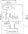
- FIG. 1 shows a prior art system 10 which uses helium as an accelerant gas.
- System 10 includes a gas/heater control console 12, a powder feeder 14, a gas heater 16, a cold spray nozzle 18 and a spray hood 20.
- the workpiece to be treated is treated in spray hood 20.
- the first stream 22 passes through powder feeder 14 and conveys a helium with powder mixture to nozzle 18 at a relatively low flow rate.
- the second stream 24 passes through gas heater 16 at a significantly higher flow rate, and is mixed with the first stream in nozzle 18 to deliver the powder entrained in helium accelerant gas at an elevated temperature and velocity.
- the temperature can be increased but is limited to a point where the nozzle will be fouled. Further, if helium is used, the expensive gas is either lost, or must be recycled using expensive equipment.
- FIG. 2 shows an illustrative embodiment of a system 50 using hydrogen.
- System 50 includes a gas control console 52, a hydrogen source 54, a powder feeder 56 and a coaxial cold spray nozzle assembly 58 for applying powder to a substrate in spray hood 60.
- Nozzle assembly 58 is also communicated with a source of shield gas, in this case nitrogen which is fed to nozzle assembly 58 through line 61.
- Powder feeder 56, nozzle assembly 58 and spray hood 60 can be positioned within a cold spray acoustic enclosure 62 as illustrated.
- a hydrogen detector 64 can be positioned in proximity to spray hood 60 to monitor for escaping hydrogen.
- Enclosure 62 is also communicated with a source 66 of outside makeup air, and a dust collector 68 is also communicated with spray hood 60.
- hydrogen is fed through one line 63 which passes through powder feeder 56 to deliver a stream of hydrogen and entrained powder particles to nozzle 58.
- Shield gas is fed through stream 61, also to nozzle assembly 58.
- Nozzle assembly 58 delivers a centered stream of hydrogen accelerant gas with entrained powder for cold spray deposition upon a workpiece, as well as a cylindrical flow of shield gas, in this case, nitrogen, surrounding the flow of hydrogen.
- the shield gas serves to dilute and safely remove hydrogen gas from the point of application, after impact with the workpiece. This prevents escape of hydrogen at elevated levels or concentrations and helps ensure safety of the process.
- Shield gas can be fed through line 61 at a significantly higher flow rate or pressure than the hydrogen accelerant gas.
- high quality cold spray deposition can be accomplished at significantly lower temperatures which avoid fouling of the nozzle.
- costs of heating of the accelerant gas can be avoided.
- hydrogen is available at a reduced cost as compared to helium.
- a system as shown in FIG. 2 can be used to produce high quality cold spray deposition using a cheaper accelerant gas and at conditions which produce higher quality deposition with less chance of fouling of the nozzle.
- FIG. 3 shows a further illustrative embodiment according to the disclosure. Similar elements with respect to FIG. 2 carry similar reference numerals.
- system 50' of FIG. 3 can be provided with a heater 70 to heat the stream of hydrogen, accelerant gas and powder, if desired. Due to the high velocity which can be accomplished using hydrogen as accelerant gas, any heating which will be necessary would be a low level of heating.
- the heater 70 as shown in FIG. 3 could be a heating coil positioned within a box or tube-type furnace. Such a configuration is shown in FIG. 4 .
- FIG. 4 shows heater 70 having a hydrogen gas tube 72 which passes through a box or tube furnace 74.
- the tube 72 can be in the form of a coil within box 74, and can be surrounded by a conduit 76 for carrying shield or inert gas such as nitrogen.
- pressure of shield gas in line 76 should be greater than pressure of hydrogen gas in line 72 so that any leaks do not result in loss of hydrogen into the work area or atmosphere.
- FIG. 5 schematically illustrates flow in accordance with the present disclosure.
- FIG. 5 shows workpiece 100 and schematically illustrates the outlet end 102 of a cold spray nozzle assembly 58.
- a centrally located stream of accelerant gas 104 is impinged upon workpiece 100 from the nozzle of cold spray assembly 58, while a cylindrical shield of gas 106 is formed around the centered stream through shield gas flowing along an annular space 108 between nozzle 110 and outer sleeve 112.
- Stream 104 engaging workpiece 100 remains substantially entirely hydrogen with entrained particles.
- shield gas 106 which prevents the escape of undiluted hydrogen defines a cylindrical shield or shroud around the stream of accelerant gas.
- arrows 114 schematically illustrate gases leaving the impact area, and these gases are diluted to the point where they contain hydrogen in an amount of up to about 5% vol.
- exit velocity is a key parameter in obtaining good results with a cold spray deposition.
- Table 1 Velocity performance of copper under various process conditions Gas Type Pressure (bar) Temperature (°c) Exit Velocity (m/s) He 30 20 674 N2 30 20 397 N2 30 1000 683 N2 60 600 666 H2 30 20 802
- the flow of hydrogen accelerant gas can advantageously comprise a majority of hydrogen. More ideally, the accelerant gas can comprise at least 70% volume of hydrogen, more preferably at least 90% of volume hydrogen.
- the stream of accelerant gas can advantageously be fed to the workpiece at a critical velocity ratio, or CVR (the ratio of particle velocity to the critical velocity for particle bonding), of at least one, and more desirably at a critical velocity ratio of between 1.5 and 2.0.
- CVRs can be achieved at a temperature of the stream of accelerant gas of about 20°C when spraying copper particles with an average particle size of 20 ⁇ m and a gas pressure of 20 bar (2 MPa).
- relatively high strength aluminum alloy powder such as aluminum alloy 6061, with an average particle size of about 30 pm, can achieve this same CVR range with a hydrogen gas temperature of only 100°C and a pressure of 20 bar (2 MPa).
- the shield gas can advantageously be any gas which remains substantially inert at conditions likely to be encountered during the process. More specifically, the shield gas can be selected from the group consisting of inert gases and gases which are substantially inert with the substrate and metal powder at temperatures of the stream of accelerant gas and mixtures thereof. In a further non-limiting aspect of the disclosure, the shield gas can be selected from the group of nitrogen, argon, carbon dioxide, and mixtures thereof, most preferably nitrogen.
- the substrate and powder materials can be any metals or ceramic-metal composites including aluminum, copper, nickel, iron, tantalum, niobium, cobalt or mixtures or alloys thereof.
- the particles when the particles are aluminum, the particles desirably have a particle size of between 20 and 40 ⁇ m.
- the metal powder material is particles of copper, these particles can be provided at a particle size of between 10 and 30 ⁇ m. Other desirable particle size ranges would be applicable to other metals and alloys where generally higher density and higher strength materials require lower particle size ranges.
- FIG. 6 shows a cold spray nozzle assembly 58 according to the present disclosure mounted to a robot arm 200 which can be utilized and controlled to position nozzle 58 relative to 100.
- FIG. 7 is an enlarged view of the nozzle portion of FIG. 6 , and shows nozzle assembly 58 with a split clamp 202 for mounting nozzle assembly 58 to arm 200.
- Inlets 204, 206 lead through split clamp 202 and can be used to feed accelerant gas and powder to nozzle assembly 58 described above. This leads to a stream of accelerant gas and powder which exits nozzle assembly 58 at an outlet end 208 to impact workpiece 100.
- An inlet 210 is shown which can be used to feed shield gas into a space between an outer sleeve 212 and the inner nozzle structure 214.
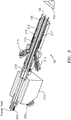
- FIG. 8 is a perspective view similar to that shown in FIG. 7 , and further illustrates an annular space 216 through which shield gas flows during operation of the device.
- FIG. 9 a sectional view of the nozzle assembly 58 as shown in FIG. 8 is presented, and further illustrates internal structure and gas flow of the apparatus according to this structure.
- Inlets 204, 206 are shown through which powder feed and hydrogen gas feed can be conducted into a central flow area 218 which leads into the nozzle jet of nozzle 214 to produce a stream 104 of hydrogen accelerant gas with entrained powder particles for impacting workpiece 100 as desired.
- FIG. 9 shows two inlets 210 through which shield gas are introduced into an annular space 216 between sleeve 212 and nozzle 214.
- a bulkhead 217 can be positioned within annular space and have through-passages or perforations to allow shield gas to pass through bulkhead 217.
- Such a configuration can help to produce a smooth and uniform flow of shield gas in a cylindrical pattern as desired.
- FIG. 10 shows a side view of a further configuration of a hydrogen cold spray nozzle assembly.
- like numerals have again been used to depict like elements.
- One particular aspect of FIG. 10 is that a single inlet 205 is utilized for both hydrogen gas and powder. Since hydrogen can be used at relatively low or cool temperatures, the entire flow of hydrogen gas can be used to entrain the metal powders, and the entire flow can be substantially straight and aligned along the longitudinal access of stream 218 through nozzle 214. This simplifies construction of the device by removing one inlet, and is also advantageous in that the flow path of hydrogen is maintained in a straight line, therefore avoiding impact areas which could lead to fouling of the nozzle.
Landscapes
- Chemical & Material Sciences (AREA)
- Chemical Kinetics & Catalysis (AREA)
- Engineering & Computer Science (AREA)
- Materials Engineering (AREA)
- Mechanical Engineering (AREA)
- Metallurgy (AREA)
- Organic Chemistry (AREA)
- Other Surface Treatments For Metallic Materials (AREA)
Abstract
Description
- The present disclosure relates to a cold spray process which involves deposition of powdered materials through a supersonic nozzle using kinetic energy and plastic deformation upon impacting a target to consolidate the powdered materials. This occurs through a process similar to cold welding, where surface strains on the particle and the impacting substrate expose fresh metal surfaces which then bond.
- In order to achieve superior material properties through cold spray deposition, high particle velocity is required. Known cold spray processes use a combination of helium and heat to accelerate metal particles to a predetermined velocity sufficient to obtain good bonding of the metal particles with the substrate. However, helium is an expensive consumable without a reclamation system. Further, the helium gas temperature may need to be raised, increasing the sonic velocity of the gas, in turn increasing the particle impact velocity to a level which would then be sufficient to achieve good particle bonding. This increased heat can cause fouling of the nozzle, leading to a need to replace or maintain the nozzles to bring them back into service.
- Alternately, nitrogen can be used in the cold spray process for accelerating particles to sufficient velocities to achieve bonding. The sonic velocity of nitrogen at any temperature is less than half of the velocity of helium at the same spray gas temperature. As with helium, increased temperature can increase the sonic velocity of nitrogen, but very high temperatures, 600-1000°C, may be required for many materials to achieve acceptable velocity at which point many of the attractive characteristics of a cold spray deposit are lost. As in the case of higher temperature helium, it is also more likely to foul nozzles when running very high nitrogen temperatures.
- According to an aspect of the disclosure, there is provided a method for cold spray deposition of a material on a substrate comprising the steps of: entraining a metal powder material in a stream of accelerant gas comprising hydrogen; forming a flow of shield gas around the stream of accelerant gas; and impacting the substrate with the stream of accelerant gas whereby the metal powder material is deposited on the substrate.
- In a non-limiting embodiment of the method, the stream of accelerant gas comprises a majority of hydrogen.
- In a further non-limiting embodiment of the method, the stream of accelerant gas comprises at least 70% vol hydrogen.
- In a further non-limiting embodiment of the method, the stream of accelerant gas comprises at least 90% vol hydrogen.
- In a further non-limiting embodiment of the method, the stream of accelerant gas has a critical velocity ratio of at least one.
- In a further non-limiting embodiment of the method, the stream of accelerant gas has a critical velocity ratio of between 1.5 and 2.0.
- In a further non-limiting embodiment of the method, the stream of accelerant gas is at a temperature of less than about 400°C.
- In a further non-limiting embodiment of the method, the stream of accelerant gas is at a temperature of less than about 200°C.
- In a further non-limiting embodiment of the method, gas mixture leaving an area of impact of the stream of accelerant gas with the substrate has a hydrogen content of less than 5% vol.
- In a further non-limiting embodiment of the method, the shield gas is selected from the group consisting of inert gases and gas which is substantially inert with the substrate and metal powder at temperature of the stream of accelerant gas, and mixtures thereof.
- In a further non-limiting embodiment of the method, the shield gas is selected from the group consisting of nitrogen, helium, argon, carbon dioxide and mixtures thereof.
- In a further non-limiting embodiment of the method, the shield gas is nitrogen.
- In a further non-limiting embodiment of the method, the metal powder material comprises particles of aluminum, copper, nickel, iron, tantalum, niobium, cobalt, or mixtures or alloys thereof, where the particle sizes vary from about 5 µm to 40 µm.
- In a further non-limiting embodiment of the method, the metal powder material comprises particles of aluminum, copper or mixtures thereof.
- In a further non-limiting embodiment of the method, the metal powder material comprises particles of aluminum having a particle size of between 20 and 40 µm.
- In a further non-limiting embodiment of the method, the metal powder material comprises particles of copper having a particle size of between 10 and 30 µm.
- In a further non-limiting embodiment of the method, the stream of accelerant gas is passed through a nozzle before the impacting step.
- In a further non-limiting embodiment of the method, the flow of shield gas is at a higher pressure than the stream of accelerant gas.
- The disclosure also provides an apparatus for cold spray deposition of a material on a substrate comprising: a nozzle communicated with accelerant gas and metal powder to be deposited on the substrate; a sleeve surrounding the nozzle and defining an annular space around the nozzle, the annular space being communicated with a shield gas.
- In a non-limiting embodiment of the apparatus, the nozzle is defined substantially concentric within the sleeve.
- In a further non-limiting embodiment of the apparatus, the nozzle and the sleeve define an outlet for a centered stream of the accelerant gas and a cylinder of shield gas surrounding the centered stream.
- In a further non-limiting embodiment of the apparatus, a perforated bulkhead is provided in the annular space to adjust flow characteristics of the shield gas.
- A detailed description follows, with reference to the attached drawings, wherein:
-
FIG. 1 is a schematic illustration of a prior art cold spray system and method; -
FIG. 2 is a schematic illustration of a cold spray system and method in accordance with the present disclosure; -
FIG. 3 is a schematic illustration of a system and process showing a further exemplary embodiment; -
FIG. 4 shows an enlarged view of a heater for heating the accelerant gas; -
FIG. 5 schematically illustrates a non-limiting embodiment of a method of cold spray deposition; -
FIG. 6 illustrates an exemplary embodiment of a cold spray system mounted on a robot arm; -
FIG. 7 is a side elevational view of a further exemplary embodiment of a system for cold spray deposition according to the disclosure. -
FIG. 8 is a perspective view of a further exemplary embodiment of a system for cold spray deposition; -
FIG. 9 is a sectional perspective view of a further exemplary embodiment; and -
FIG. 10 is a side schematic illustration of a further non-limiting configuration of the present disclosure. - Like reference numbers and designations in the various drawings indicate like elements.
- The present disclosure relates to cold spray deposition of a material such as a metal powder or particulate on a substrate.
-
FIG. 1 shows aprior art system 10 which uses helium as an accelerant gas.System 10 includes a gas/heater control console 12, apowder feeder 14, agas heater 16, acold spray nozzle 18 and aspray hood 20. The workpiece to be treated is treated inspray hood 20. - Two streams of gas are fed to
cold spray nozzle 18. Thefirst stream 22 passes throughpowder feeder 14 and conveys a helium with powder mixture tonozzle 18 at a relatively low flow rate. Thesecond stream 24 passes throughgas heater 16 at a significantly higher flow rate, and is mixed with the first stream innozzle 18 to deliver the powder entrained in helium accelerant gas at an elevated temperature and velocity. As set forth above, in order to accomplish higher impacting velocity with either helium or nitrogen, the temperature can be increased but is limited to a point where the nozzle will be fouled. Further, if helium is used, the expensive gas is either lost, or must be recycled using expensive equipment. -
FIG. 2 shows an illustrative embodiment of asystem 50 using hydrogen.System 50 includes agas control console 52, ahydrogen source 54, apowder feeder 56 and a coaxial coldspray nozzle assembly 58 for applying powder to a substrate inspray hood 60.Nozzle assembly 58 is also communicated with a source of shield gas, in this case nitrogen which is fed tonozzle assembly 58 throughline 61.Powder feeder 56,nozzle assembly 58 andspray hood 60 can be positioned within a cold sprayacoustic enclosure 62 as illustrated. Further, ahydrogen detector 64 can be positioned in proximity tospray hood 60 to monitor for escaping hydrogen. -
Enclosure 62 is also communicated with asource 66 of outside makeup air, and adust collector 68 is also communicated withspray hood 60. In operation, hydrogen is fed through oneline 63 which passes throughpowder feeder 56 to deliver a stream of hydrogen and entrained powder particles to nozzle 58. Shield gas is fed throughstream 61, also tonozzle assembly 58.Nozzle assembly 58 delivers a centered stream of hydrogen accelerant gas with entrained powder for cold spray deposition upon a workpiece, as well as a cylindrical flow of shield gas, in this case, nitrogen, surrounding the flow of hydrogen. The shield gas serves to dilute and safely remove hydrogen gas from the point of application, after impact with the workpiece. This prevents escape of hydrogen at elevated levels or concentrations and helps ensure safety of the process. Shield gas can be fed throughline 61 at a significantly higher flow rate or pressure than the hydrogen accelerant gas. With a system as illustrated inFIG. 2 , high quality cold spray deposition can be accomplished at significantly lower temperatures which avoid fouling of the nozzle. Further, in this non-limiting example, costs of heating of the accelerant gas can be avoided. Finally, hydrogen is available at a reduced cost as compared to helium. Thus, a system as shown inFIG. 2 can be used to produce high quality cold spray deposition using a cheaper accelerant gas and at conditions which produce higher quality deposition with less chance of fouling of the nozzle. -
FIG. 3 shows a further illustrative embodiment according to the disclosure. Similar elements with respect toFIG. 2 carry similar reference numerals. In this regard, however, system 50' ofFIG. 3 can be provided with aheater 70 to heat the stream of hydrogen, accelerant gas and powder, if desired. Due to the high velocity which can be accomplished using hydrogen as accelerant gas, any heating which will be necessary would be a low level of heating. Thus, theheater 70 as shown inFIG. 3 could be a heating coil positioned within a box or tube-type furnace. Such a configuration is shown inFIG. 4 . -
FIG. 4 showsheater 70 having ahydrogen gas tube 72 which passes through a box ortube furnace 74. Thetube 72 can be in the form of a coil withinbox 74, and can be surrounded by aconduit 76 for carrying shield or inert gas such as nitrogen. In this regard, pressure of shield gas inline 76 should be greater than pressure of hydrogen gas inline 72 so that any leaks do not result in loss of hydrogen into the work area or atmosphere. -
FIG. 5 schematically illustrates flow in accordance with the present disclosure.FIG. 5 shows workpiece 100 and schematically illustrates theoutlet end 102 of a coldspray nozzle assembly 58. As shown, a centrally located stream ofaccelerant gas 104 is impinged uponworkpiece 100 from the nozzle ofcold spray assembly 58, while a cylindrical shield ofgas 106 is formed around the centered stream through shield gas flowing along anannular space 108 betweennozzle 110 andouter sleeve 112.Stream 104 engagingworkpiece 100 remains substantially entirely hydrogen with entrained particles. Thus,shield gas 106, which prevents the escape of undiluted hydrogen defines a cylindrical shield or shroud around the stream of accelerant gas. After impactingworkpiece 100,arrows 114 schematically illustrate gases leaving the impact area, and these gases are diluted to the point where they contain hydrogen in an amount of up to about 5% vol. - As set forth above, exit velocity (m/s) is a key parameter in obtaining good results with a cold spray deposition. Table 1 below sets forth pressure temperature and exit velocity for several different types of accelerant gas. As shown, helium can generate an exit velocity of 674 m/s at a pressure of 30 bar (3 MPa) and a temperature of 20°C. At the same pressure and temperature, nitrogen as an accelerant gas produces an exit velocity of only 397 m/s. This velocity can be increased if either the temperature or pressure are somewhat significantly increased, as shown in Table 1 (where 1 bar = 0.1 MPa).
Table 1: Velocity performance of copper under various process conditions Gas Type Pressure (bar) Temperature (°c) Exit Velocity (m/s) He 30 20 674 N2 30 20 397 N2 30 1000 683 N2 60 600 666 H2 30 20 802 - Finally, the last line of Table 1 compares exit velocity for a stream of hydrogen as accelerant gas, and shows that exit velocity is significantly higher than it is for helium or nitrogen at the same conditions.
- The flow of hydrogen accelerant gas can advantageously comprise a majority of hydrogen. More ideally, the accelerant gas can comprise at least 70% volume of hydrogen, more preferably at least 90% of volume hydrogen.
- The stream of accelerant gas can advantageously be fed to the workpiece at a critical velocity ratio, or CVR (the ratio of particle velocity to the critical velocity for particle bonding), of at least one, and more desirably at a critical velocity ratio of between 1.5 and 2.0. Further, such CVRs can be achieved at a temperature of the stream of accelerant gas of about 20°C when spraying copper particles with an average particle size of 20 µm and a gas pressure of 20 bar (2 MPa). Similarly, relatively high strength aluminum alloy powder such as aluminum alloy 6061, with an average particle size of about 30 pm, can achieve this same CVR range with a hydrogen gas temperature of only 100°C and a pressure of 20 bar (2 MPa). Even high strength super-alloy powders such as Inconel 625 with average particle sizes of 20 µm can achieve this same CVR range with a hydrogen gas temperature of only 200°C and a pressure of 35 bar (3.5 MPa). Generally, temperatures higher than 200°C are not needed for most metals or alloys of the particle size ranges discussed. However some metals may experience benefits due to higher temperature accelerating gases. Gas temperatures as high as 400°C or even higher are possible with the heating arrangement described, but increases in temperature will add to the system complexity with higher temperature capably hardware, hose flexibility, and even hydrogen absorption into some metals and alloys.
- The shield gas can advantageously be any gas which remains substantially inert at conditions likely to be encountered during the process. More specifically, the shield gas can be selected from the group consisting of inert gases and gases which are substantially inert with the substrate and metal powder at temperatures of the stream of accelerant gas and mixtures thereof. In a further non-limiting aspect of the disclosure, the shield gas can be selected from the group of nitrogen, argon, carbon dioxide, and mixtures thereof, most preferably nitrogen.
- The substrate and powder materials can be any metals or ceramic-metal composites including aluminum, copper, nickel, iron, tantalum, niobium, cobalt or mixtures or alloys thereof. In one aspect of the present disclosure, when the particles are aluminum, the particles desirably have a particle size of between 20 and 40 µm. When the metal powder material is particles of copper, these particles can be provided at a particle size of between 10 and 30 µm. Other desirable particle size ranges would be applicable to other metals and alloys where generally higher density and higher strength materials require lower particle size ranges.
-
FIG. 6 shows a coldspray nozzle assembly 58 according to the present disclosure mounted to arobot arm 200 which can be utilized and controlled to positionnozzle 58 relative to 100. -
FIG. 7 is an enlarged view of the nozzle portion ofFIG. 6 , and showsnozzle assembly 58 with asplit clamp 202 for mountingnozzle assembly 58 toarm 200.Inlets split clamp 202 and can be used to feed accelerant gas and powder tonozzle assembly 58 described above. This leads to a stream of accelerant gas and powder which exitsnozzle assembly 58 at anoutlet end 208 to impactworkpiece 100. Aninlet 210 is shown which can be used to feed shield gas into a space between anouter sleeve 212 and theinner nozzle structure 214.FIG. 8 is a perspective view similar to that shown inFIG. 7 , and further illustrates anannular space 216 through which shield gas flows during operation of the device. - Turning to
FIG. 9 , a sectional view of thenozzle assembly 58 as shown inFIG. 8 is presented, and further illustrates internal structure and gas flow of the apparatus according to this structure.Inlets central flow area 218 which leads into the nozzle jet ofnozzle 214 to produce astream 104 of hydrogen accelerant gas with entrained powder particles for impactingworkpiece 100 as desired. - The embodiment of
FIG. 9 shows twoinlets 210 through which shield gas are introduced into anannular space 216 betweensleeve 212 andnozzle 214. Thecylindrical flow 106 of shield gas, around thestream 104 of hydrogen accelerant gas, which serves to sufficiently dilute hydrogen concentration after impactingworkpiece 100 such that gases leaving the area of impact withworkpiece 100 are at sufficiently reduced levels of hydrogen, particularly before they encounter air or oxygen. - In this configuration, a
bulkhead 217 can be positioned within annular space and have through-passages or perforations to allow shield gas to pass throughbulkhead 217. Such a configuration can help to produce a smooth and uniform flow of shield gas in a cylindrical pattern as desired. -
FIG. 10 shows a side view of a further configuration of a hydrogen cold spray nozzle assembly. In this configuration, like numerals have again been used to depict like elements. One particular aspect ofFIG. 10 , however, is that asingle inlet 205 is utilized for both hydrogen gas and powder. Since hydrogen can be used at relatively low or cool temperatures, the entire flow of hydrogen gas can be used to entrain the metal powders, and the entire flow can be substantially straight and aligned along the longitudinal access ofstream 218 throughnozzle 214. This simplifies construction of the device by removing one inlet, and is also advantageous in that the flow path of hydrogen is maintained in a straight line, therefore avoiding impact areas which could lead to fouling of the nozzle. - It should be appreciated that the various configurations described and illustrated herein provide for use of hydrogen as an accelerant in a cold spray process to overcome cost and fouling issues in helium-based systems and methods, and to improve quality of results of the cold spray deposition, while maintaining a safe shield of nitrogen or other effectively inert and/or diluting gas around the stream of hydrogen such that the hydrogen is diluted and removed from the impact area with the workpiece after impact is conducted.
- One or more embodiments of the present invention have been described. Nevertheless, it will be understood that various modifications may be made without departing from the scope of the invention. Accordingly, other embodiments are within the scope of the following claims.
Claims (15)
- A method for cold spray deposition of a material on a substrate (100), comprising the steps of:entraining a metal powder material in a stream of accelerant gas (104) comprising hydrogen;forming a flow of shield gas (106) around the stream of accelerant gas (104); andimpacting the substrate (100) with the stream of accelerant gas (104) whereby the metal powder material is deposited on the substrate (100).
- The method of claim 1, wherein the stream of accelerant gas (104) comprises a majority of hydrogen, optionally at least 70% vol hydrogen, or at least 90% vol hydrogen.
- The method of claim 1 or 2, wherein the stream of accelerant gas (104) has a critical velocity ratio of at least one, and optionally between 1.5 and 2.0.
- The method of any of claims 1 to 3, wherein the stream of accelerant gas (104) is at a temperature of less than about 400°C, and optionally less than about 200°C.
- The method of any preceding claim, wherein gas mixture (114) leaving an area of impact of the stream of accelerant gas (104) with the substrate (100) has a hydrogen content of less than 5% vol.
- The method of any preceding claim, wherein the shield gas (106) is selected from the group consisting of inert gases and gas which is substantially inert with the substrate (100) and metal powder at temperature of the stream of accelerant gas (104), and mixtures thereof.
- The method of any preceding claim, wherein the shield gas (106) is selected from the group consisting of nitrogen, helium, argon, carbon dioxide and mixtures thereof.
- The method of any preceding claim, wherein the metal powder material comprises particles of aluminum, copper, nickel, iron, tantalum, niobium, cobalt, or mixtures or alloys thereof, where the particle sizes vary from about 5 µm to 40 µm.
- The method of any preceding claim, wherein the metal powder material comprises:particles of aluminum having a particle size of between 20 and 40 µm; orparticles of copper having a particle size of between 10 and 30 µm.
- The method of any preceding claim, wherein the stream of accelerant gas (104) is passed through a nozzle (110; 214) before the impacting step.
- The method of any preceding claim, wherein the flow of shield gas (106) is at a higher pressure than the stream of accelerant gas (104).
- An apparatus for cold spray deposition of a material on a substrate (100), comprising:a nozzle (110; 214) communicated with accelerant gas (104) and metal powder to be deposited on a substrate (100); anda sleeve (112; 212) surrounding the nozzle (110; 214) and defining an annular space (108; 216) around the nozzle (110; 214), the annular space (108; 216) being communicated with a shield gas (106).
- The apparatus of claim 12, wherein the nozzle (110; 214) is defined substantially concentric within the sleeve (112; 212).
- The apparatus of claim 12 or 13, wherein the nozzle (110; 214) and the sleeve (112; 212) define an outlet for a centered stream of the accelerant gas (104) and a cylinder of shield gas (106) surrounding the centered stream (104).
- The apparatus of any of claims 12 to 14, further comprising a perforated bulkhead (217) in the annular space (108; 216) to adjust flow characteristics of the shield gas (106).
Applications Claiming Priority (1)
| Application Number | Priority Date | Filing Date | Title |
|---|---|---|---|
| US15/653,582 US20190024242A1 (en) | 2017-07-19 | 2017-07-19 | Hydrogen based cold spray nozzle and method |
Publications (1)
| Publication Number | Publication Date |
|---|---|
| EP3431630A1 true EP3431630A1 (en) | 2019-01-23 |
Family
ID=63142929
Family Applications (1)
| Application Number | Title | Priority Date | Filing Date |
|---|---|---|---|
| EP18184451.5A Withdrawn EP3431630A1 (en) | 2017-07-19 | 2018-07-19 | Hydrogen based cold spray nozzle and method |
Country Status (2)
| Country | Link |
|---|---|
| US (1) | US20190024242A1 (en) |
| EP (1) | EP3431630A1 (en) |
Cited By (3)
| Publication number | Priority date | Publication date | Assignee | Title |
|---|---|---|---|---|
| US11662300B2 (en) | 2019-09-19 | 2023-05-30 | Westinghouse Electric Company Llc | Apparatus for performing in-situ adhesion test of cold spray deposits and method of employing |
| US11898986B2 (en) | 2012-10-10 | 2024-02-13 | Westinghouse Electric Company Llc | Systems and methods for steam generator tube analysis for detection of tube degradation |
| US11935662B2 (en) | 2019-07-02 | 2024-03-19 | Westinghouse Electric Company Llc | Elongate SiC fuel elements |
Citations (1)
| Publication number | Priority date | Publication date | Assignee | Title |
|---|---|---|---|---|
| WO2002085532A1 (en) * | 2001-04-24 | 2002-10-31 | Innovative Technology, Inc. | A apparatus and process for solid-state deposition and consolidation of high velocity powder particles using thermal plastic deformation |
Family Cites Families (3)
| Publication number | Priority date | Publication date | Assignee | Title |
|---|---|---|---|---|
| US9168546B2 (en) * | 2008-12-12 | 2015-10-27 | National Research Council Of Canada | Cold gas dynamic spray apparatus, system and method |
| CN106029948B (en) * | 2014-01-17 | 2020-02-21 | Iones株式会社 | Method for forming a ceramic coating with improved plasma resistance and ceramic coating formed therefrom |
| US10329670B2 (en) * | 2015-11-04 | 2019-06-25 | Tessonics, Inc. | Apparatus and method for cold spraying and coating processing |
-
2017
- 2017-07-19 US US15/653,582 patent/US20190024242A1/en not_active Abandoned
-
2018
- 2018-07-19 EP EP18184451.5A patent/EP3431630A1/en not_active Withdrawn
Patent Citations (1)
| Publication number | Priority date | Publication date | Assignee | Title |
|---|---|---|---|---|
| WO2002085532A1 (en) * | 2001-04-24 | 2002-10-31 | Innovative Technology, Inc. | A apparatus and process for solid-state deposition and consolidation of high velocity powder particles using thermal plastic deformation |
Cited By (3)
| Publication number | Priority date | Publication date | Assignee | Title |
|---|---|---|---|---|
| US11898986B2 (en) | 2012-10-10 | 2024-02-13 | Westinghouse Electric Company Llc | Systems and methods for steam generator tube analysis for detection of tube degradation |
| US11935662B2 (en) | 2019-07-02 | 2024-03-19 | Westinghouse Electric Company Llc | Elongate SiC fuel elements |
| US11662300B2 (en) | 2019-09-19 | 2023-05-30 | Westinghouse Electric Company Llc | Apparatus for performing in-situ adhesion test of cold spray deposits and method of employing |
Also Published As
| Publication number | Publication date |
|---|---|
| US20190024242A1 (en) | 2019-01-24 |
Similar Documents
| Publication | Publication Date | Title |
|---|---|---|
| DE60210267T2 (en) | DEVICE AND METHOD FOR THE SOLIDAGE APPLICATION AND COMPRESSION OF POWDER PARTICLES BY MEANS OF HIGH SPEED AND THERMALLY PLASTIC FORMING | |
| US20240207933A1 (en) | Process And Apparatus For Producing Powder Particles By Atomization Of A Feed Material In The Form Of An Elongated Member | |
| EP0323185B1 (en) | Apparatus and process for producing high density thermal spray coatings | |
| EP3431630A1 (en) | Hydrogen based cold spray nozzle and method | |
| CN106604800B (en) | Welding equipment including welding cooling equipment | |
| US20030232132A1 (en) | Method and apparatus for low pressure cold spraying | |
| US10808323B2 (en) | Cold spray nozzles | |
| JPH06507679A (en) | Coaxial nozzle for surface treatment under laser irradiation while feeding powdered materials | |
| US20230398606A1 (en) | Printing Heads and Associated Methods | |
| JPS5852023B2 (en) | Thermospray method for the production of aluminum porous boiling surfaces | |
| CN101909807A (en) | Laser welding method using a nozzle capable of stabilizing pores | |
| GB2455086A (en) | Weld Cooling | |
| JPH0771689B2 (en) | Method and device for supplying a flowable component to the inner surface of a hollow body | |
| JPH03192697A (en) | Temperature and speed lowering prevention method for shield plasma jet | |
| JP6644070B2 (en) | Thermal spraying method integrating selective removal of particles | |
| JP2007211331A (en) | Coating apparatus and coating method | |
| US11371785B2 (en) | Cooling system and fabrication method thereof | |
| JPS58202062A (en) | Thermal spray method and apparatus | |
| US20050074560A1 (en) | Correcting defective kinetically sprayed surfaces | |
| EP3928926A1 (en) | Device and method for cooling components, in particular in gas-shielded welding or in generative manufacture by means of gas-shielded welding, with a co2 particle beam | |
| JP2020503441A (en) | Apparatus and method for producing titanium powder | |
| JP6715694B2 (en) | Plasma spraying equipment | |
| JP6125888B2 (en) | Method for forming sprayed coating by plasma spraying method and method for manufacturing member for heat exchanger | |
| Tan et al. | Residual stress analysis of WC-Co solid components formed by the HVOF thermal spraying process | |
| JPH07110984B2 (en) | How to spray tungsten carbide |
Legal Events
| Date | Code | Title | Description |
|---|---|---|---|
| PUAI | Public reference made under article 153(3) epc to a published international application that has entered the european phase |
Free format text: ORIGINAL CODE: 0009012 |
|
| STAA | Information on the status of an ep patent application or granted ep patent |
Free format text: STATUS: THE APPLICATION HAS BEEN PUBLISHED |
|
| AK | Designated contracting states |
Kind code of ref document: A1 Designated state(s): AL AT BE BG CH CY CZ DE DK EE ES FI FR GB GR HR HU IE IS IT LI LT LU LV MC MK MT NL NO PL PT RO RS SE SI SK SM TR |
|
| AX | Request for extension of the european patent |
Extension state: BA ME |
|
| STAA | Information on the status of an ep patent application or granted ep patent |
Free format text: STATUS: REQUEST FOR EXAMINATION WAS MADE |
|
| 17P | Request for examination filed |
Effective date: 20190723 |
|
| RBV | Designated contracting states (corrected) |
Designated state(s): AL AT BE BG CH CY CZ DE DK EE ES FI FR GB GR HR HU IE IS IT LI LT LU LV MC MK MT NL NO PL PT RO RS SE SI SK SM TR |
|
| STAA | Information on the status of an ep patent application or granted ep patent |
Free format text: STATUS: THE APPLICATION HAS BEEN WITHDRAWN |
|
| 18W | Application withdrawn |
Effective date: 20201009 |