EP3431578A1 - Cell culture vessel - Google Patents
Cell culture vessel Download PDFInfo
- Publication number
- EP3431578A1 EP3431578A1 EP16894395.9A EP16894395A EP3431578A1 EP 3431578 A1 EP3431578 A1 EP 3431578A1 EP 16894395 A EP16894395 A EP 16894395A EP 3431578 A1 EP3431578 A1 EP 3431578A1
- Authority
- EP
- European Patent Office
- Prior art keywords
- culture solution
- cell culture
- weir
- storage container
- culture
- Prior art date
- Legal status (The legal status is an assumption and is not a legal conclusion. Google has not performed a legal analysis and makes no representation as to the accuracy of the status listed.)
- Pending
Links
Images



Classifications
-
- C—CHEMISTRY; METALLURGY
- C12—BIOCHEMISTRY; BEER; SPIRITS; WINE; VINEGAR; MICROBIOLOGY; ENZYMOLOGY; MUTATION OR GENETIC ENGINEERING
- C12M—APPARATUS FOR ENZYMOLOGY OR MICROBIOLOGY; APPARATUS FOR CULTURING MICROORGANISMS FOR PRODUCING BIOMASS, FOR GROWING CELLS OR FOR OBTAINING FERMENTATION OR METABOLIC PRODUCTS, i.e. BIOREACTORS OR FERMENTERS
- C12M29/00—Means for introduction, extraction or recirculation of materials, e.g. pumps
- C12M29/10—Perfusion
-
- C—CHEMISTRY; METALLURGY
- C12—BIOCHEMISTRY; BEER; SPIRITS; WINE; VINEGAR; MICROBIOLOGY; ENZYMOLOGY; MUTATION OR GENETIC ENGINEERING
- C12M—APPARATUS FOR ENZYMOLOGY OR MICROBIOLOGY; APPARATUS FOR CULTURING MICROORGANISMS FOR PRODUCING BIOMASS, FOR GROWING CELLS OR FOR OBTAINING FERMENTATION OR METABOLIC PRODUCTS, i.e. BIOREACTORS OR FERMENTERS
- C12M23/00—Constructional details, e.g. recesses, hinges
- C12M23/02—Form or structure of the vessel
- C12M23/16—Microfluidic devices; Capillary tubes
-
- C—CHEMISTRY; METALLURGY
- C12—BIOCHEMISTRY; BEER; SPIRITS; WINE; VINEGAR; MICROBIOLOGY; ENZYMOLOGY; MUTATION OR GENETIC ENGINEERING
- C12M—APPARATUS FOR ENZYMOLOGY OR MICROBIOLOGY; APPARATUS FOR CULTURING MICROORGANISMS FOR PRODUCING BIOMASS, FOR GROWING CELLS OR FOR OBTAINING FERMENTATION OR METABOLIC PRODUCTS, i.e. BIOREACTORS OR FERMENTERS
- C12M29/00—Means for introduction, extraction or recirculation of materials, e.g. pumps
-
- C—CHEMISTRY; METALLURGY
- C12—BIOCHEMISTRY; BEER; SPIRITS; WINE; VINEGAR; MICROBIOLOGY; ENZYMOLOGY; MUTATION OR GENETIC ENGINEERING
- C12M—APPARATUS FOR ENZYMOLOGY OR MICROBIOLOGY; APPARATUS FOR CULTURING MICROORGANISMS FOR PRODUCING BIOMASS, FOR GROWING CELLS OR FOR OBTAINING FERMENTATION OR METABOLIC PRODUCTS, i.e. BIOREACTORS OR FERMENTERS
- C12M3/00—Tissue, human, animal or plant cell, or virus culture apparatus
-
- C—CHEMISTRY; METALLURGY
- C12—BIOCHEMISTRY; BEER; SPIRITS; WINE; VINEGAR; MICROBIOLOGY; ENZYMOLOGY; MUTATION OR GENETIC ENGINEERING
- C12M—APPARATUS FOR ENZYMOLOGY OR MICROBIOLOGY; APPARATUS FOR CULTURING MICROORGANISMS FOR PRODUCING BIOMASS, FOR GROWING CELLS OR FOR OBTAINING FERMENTATION OR METABOLIC PRODUCTS, i.e. BIOREACTORS OR FERMENTERS
- C12M41/00—Means for regulation, monitoring, measurement or control, e.g. flow regulation
-
- C—CHEMISTRY; METALLURGY
- C12—BIOCHEMISTRY; BEER; SPIRITS; WINE; VINEGAR; MICROBIOLOGY; ENZYMOLOGY; MUTATION OR GENETIC ENGINEERING
- C12M—APPARATUS FOR ENZYMOLOGY OR MICROBIOLOGY; APPARATUS FOR CULTURING MICROORGANISMS FOR PRODUCING BIOMASS, FOR GROWING CELLS OR FOR OBTAINING FERMENTATION OR METABOLIC PRODUCTS, i.e. BIOREACTORS OR FERMENTERS
- C12M41/00—Means for regulation, monitoring, measurement or control, e.g. flow regulation
- C12M41/44—Means for regulation, monitoring, measurement or control, e.g. flow regulation of volume or liquid level
Definitions
- the present invention relates to a cell culture container in which a well for culturing cells is provided therein, and the well is immersed in a culture solution to culture a cell cluster.
- a cell culture plate in which microwells (hereinafter simply called as wells) for culturing a cell cluster are formed in a plate has been proposed and put to practical use.
- a cell culture plate in addition to a single hole plate, there are multiwell plates having a plurality of wells such as 6 holes or 24 holes (see, for example, Patent Document 1 and Patent Document 2).
- the cell culture plate When culturing a cell cluster using such a cell culture plate, the cell culture plate is placed at the bottom of a container (storage container) for storing a culture solution for culturing cells, and the cells are seeded in each well. The cells seeded in each well settle in the microwells and form a cluster in each well.
- a cell culture plate provided with a plurality of wells having uniform size, it is possible to efficiently prepare a cell cluster having uniform size.
- an object of the present invention is to facilitate replacement of a culture solution.
- a cell culture container includes a storage container, a cell culture area, a culture solution supply unit, a discharge unit, and a rectification unit.
- the storage container stores a culture solution.
- the cell culture area is an area provided in a storage container for culturing cells.
- the culture solution supply unit supplies a culture solution to the cell culture area at a flow rate equal to or less than a predetermined flow rate.
- the discharge unit discharges the culture solution in the culture area to the outside of the storage container.
- a plurality of outflow ports are uniformly arranged in a direction perpendicular to the flow direction of the culture solution from the culture solution supply unit to the discharge unit.
- the culture container may be an airtight container specified in the Japanese Pharmacopoeia. More specifically, it is a container that prevents infiltration of solids and liquids during normal handling, transportation and storage, and the outflow of the contents, and is a container that ensures ventilation for culturing. This makes it possible to maintain a safe culture environment more easily at the time of culture, open the airtight container only at the initial stage of replacement of the medium, remove the waste medium, and add fresh medium.
- it may be a sealed container specified in the Japanese Pharmacopoeia.
- it is further preferable to create a communication path so as not to cause an imbalance in pressure due to a change in the liquid amount of the culture solution supply unit or the discharge unit, or perform treatment such as opening the sealed container and flowing a gas.
- the "predetermined flow rate” that is the culture solution supply flow rate of the culture solution supply unit refers to a flow rate in which the cells retained in the cell culture area are not rolled up or flowed by the flow of the culture solution, and a laminar flow is generated in the cell culture area.
- a flow rate is, for example, a flow rate of 2 mL/min or less.
- the discharge unit preferably has a discharge port for discharging a liquid in the storage container to the outside of the storage container and a weir provided higher than the height of the upper surface of the cell culture unit in the cell culture area, and is configured so that only a liquid that flows over the weir is guided to the discharge port. Then, while the liquid surface height of the culture solution in the culture solution supply unit is maintained higher than the height of the upper surface of the cell culture unit, the old culture solution swept away by the new culture solution supplied to the cell culture area by the culture solution supply unit is automatically discarded from the discharge port to the outside of the storage container. By these actions, replacement work of the culture solution in the storage container is facilitated, and it is possible to prevent the cells retained in the cell culture area from getting out of the wells or being discarded together with the old culture solution.
- the culture solution supply unit may have a culture solution reservoir for storing a culture solution above the storage container and supply the culture solution stored in the culture solution reservoir by the own weight of the culture solution in the culture solution reservoir. Then, the configuration of the cell culture container can be simplified. Then, simply by placing a culture solution in the culture solution reservoir, the culture solution is automatically supplied into the storage container at a flow rate equal to or less than the predetermined flow rate by the own weight of the culture solution in the culture solution reservoir, so that the replacement work of the culture solution is facilitated.
- the culture solution when the culture solution flows over the weir, the culture solution rises at the upper end of the weir due to the surface tension of the culture solution, and the liquid surface height of the culture solution becomes higher than the height of the weir.
- a pressure difference called Laplace pressure is generated across the liquid surface of the culture solution, and when the Laplace pressure cannot support the mass of the culture solution, the weir breaks down and the culture solution flows over the weir.
- the magnitude of the Laplace pressure ⁇ P generated in the culture solution is expressed as the product of the surface tension and the surface curvature of the liquid surface at that point, as shown in the formula (1).
- the surface curvature is the sum of the curvatures of the sections when the curved surface is cut in two directions orthogonal to each other.
- ⁇ is the surface tension and is a variable specific to the liquid.
- 1/R 1 is the curvature of the section when the liquid surface is cut in the vertical direction
- 1/R 2 is the curvature of the section when the liquid surface is cut in the horizontal direction.
- ⁇ P ⁇ 1 / R 1 + 1 / R 2
- the magnitude of the Laplace pressure ⁇ P varies depending on the planar shape of the weir.
- the shape of the liquid surface changes so as to balance it, and the curvature 1/R 1 increases.
- the Laplace pressure ⁇ P loses the gravity and the dam breaks down, and the culture solution flows over the weir.
- 1/R 2 is always negative when the planar shape of the weir is curved in a convex shape in a direction opposite to the flow direction of the culture solution, and the Laplace pressure ⁇ P becomes small as compared to the case where the planar shape of the weir is linear.
- the Laplace pressure ⁇ P decreases, the liquid surface height of the culture solution rising on the weir also becomes lower, thus the culture solution easily flows over the weir to be guided to the discharge flow path.
- the old culture solution is smoothly discarded through the discharge flow path, thus the replacement of the culture solution in the storage container can be smoothly performed.
- the weir provided in the discharge unit has a portion in which the planar shape at the top end is curved in a convex shape toward the cell culture area side.
- the fact that the planar shape of the weir has a portion curved in a convex shape toward the cell culture area side means that a portion that "is curved in a convex shape in a direction opposite to the flow direction of the culture solution" is provided on the planar shape of the weir.
- the culture solution passes through the cell culture area and reaches the discharge unit.
- the Laplace pressure ⁇ P becomes smaller than in the case where the planar shape of the weir is linear, the culture solution easily flows over the weir to be guided to the discharge flow path. As a result, the replacement of the culture solution in the storage container is smoothly performed.
- Example of a preferred embodiment of the above case include an embodiment in which the planar shape of the weir is an annular shape, and the discharge port is provided inside the weir. That is, at least the upper end portion of the weir has a circular pipe shape.
- the curvature 1/R 2 at an arbitrary point of the culture solution going to flow over the weir is D
- the radius of curvature of the weir is D
- the horizontal distance from the edge of the opening of the weir upper end at that point is r
- the discharge port is an upper end of a downwardly extending discharge flow path
- the discharge flow path has a capillary portion having an inner diameter of 2 mm or less and a hydrophilic inner surface, and the capillary portion communicates with the discharge port. Then, the culture solution flowing over the weir is drawn into the discharge flow path by capillary force, so that the old culture solution can be discarded more smoothly.
- a waste liquid reservoir for receiving the liquid discharged to the outside of the storage container through the discharge flow path is provided below the storage container, and when the discharge flow path extends vertically downward from the inside of the storage container and drips the waste liquid to the waste liquid reservoir, it is preferable that the inner diameter of the capillary portion increases as it goes downward.
- the inner diameter of the capillary portion of the discharge flow path is small, it is considered that the liquid is likely to stay in the capillary portion and the culture solution cannot be discarded smoothly. Such an inconvenience can be alleviated by increasing the inner diameter of the capillary portion of the discharge flow path as it goes downward.
- a droplet of the culture solution is formed at the lower end of the discharge flow path, and when the outer diameter of the droplet is small, the Laplace pressure generated in the droplet becomes large, and the culture solution is less likely to be dropped from the discharge flow path to the waste liquid reservoir. Therefore, it is preferable that the length and the inner diameter of the lower end of the capillary portion are set so that the Laplace pressure generated on the liquid surface formed at the lower end of the capillary portion is smaller than the gravity of the liquid in the capillary portion. Then, the culture solution drawn into the capillary portion is likely to descend by the own weight, and it is possible to prevent the culture solution from clogging in the capillary portion.
- the discharge flow path preferably has, below the capillary portion, an enlarged portion having an inner diameter larger than the inner diameter of the lower end of the capillary portion and having an open lower portion. Then, the outer diameter of the liquid surface formed at the downstream end of the discharge flow path becomes large, and the Laplace pressure generated on the liquid surface of the culture solution at the lower end of the discharge flow path decreases. As a result, the culture solution is likely to be dropped from the lower end of the discharge flow path to the waste liquid reservoir, and discard of the culture solution is promoted.
- a cross section of the upper end portion of the weir has an acute angle shape converging upward, that is, there is no flat surface at the upper end portion of the weir, and the outer diameter of the upper end portion of the weir is very close to the inner diameter of the inside thereof.
- the Laplace pressure ⁇ P can be reduced, and when the liquid surface attempts to protrude inward from the edge of the weir, the liquid surfaces come into contact with each other on the weir and flow into the discharge flow path, so that the maximum value that 1/R 1 in the formula (4) can take becomes even smaller, and the discard of the culture solution flowing over the weir is more smoothed.
- examples of a preferred embodiment of the rectification unit include those including a rectification path in which a plurality of flow paths parallel to a solvent flow direction from a culture solution supply unit side to a discharge unit side of the cell culture area are uniformly arranged in a direction perpendicular to the solvent flow direction in the horizontal plane.
- the new culture solution supplied to the storage container is likely to flow on the surface layer side of the culture solution stored in the storage container, and the culture solution located on the bottom surface side of the storage container is less likely to be replaced while the culture solution on the surface layer side is replaced. Therefore, it is preferable that each of the flow paths constituting the rectification path is configured to block the liquid on the surface layer side in the storage container and pass the liquid on the bottom layer side of the storage container. Then, since the new culture solution is supplied from the vicinity of the bottom surface of the storage container to the cell culture area, the culture solution located on the bottom surface side of the storage container is also likely to be replaced.
- the cell culture container according to the present invention includes a culture solution supply unit for supplying a culture solution into a storage container from one end side of a cell culture area at a flow rate equal to or less than a predetermined flow rate, it is possible to supply a new culture solution to the cell culture area at a flow rate equal to or less than a predetermined flow rate.
- the flow velocity distribution of a new culture solution supplied by the culture solution supply unit in the plane of the cell culture area becomes uniform, and the culture solution in the entire cell culture area can be easily and uniformly replaced with the new culture solution.
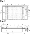
- a cell culture container 1 includes a frame 2, a culture solution reservoir 4, a dimple membrane 8, and a waste liquid reservoir 24.
- the dimple membrane 8 is a member on the plate, and a plurality of microwells for culturing cells are arranged on one side.
- the dimple membrane 8 is attached to the frame 2 in a state where the surface on the side where the microwells are arranged is on the upper side.
- Side walls 6, 10, 11 are provided on the upper surface side of the frame 2, and the dimple membrane 8 attached to the frame 2 and the side walls 6, 10, 11 form a storage container 5 of a culture solution with the dimple membrane 8 as the bottom surface.
- the dimple membrane 8 has microwells in a plane between a rectification path 20 and a rectification path 22, which will be described later.
- the area of the dimple membrane 8 surrounded by a broken line where the microwells are arranged is called as a cell culture area 9.
- the cell culture area 9 has a rectangular shape, but it may have a circular shape, an oval shape or another shape.
- a plurality of microwells are arranged in the cell culture area 9, but the wells are not necessarily need to be arranged, as long as they can be cultured by retaining cells.
- the upper surface of the storage container 5 is opened, but the upper surface of the storage container 5 does not necessarily need to be opened, and may be sealed to be an airtight container. This makes it possible to maintain a safe culture environment more easily at the time of culture, open the airtight container only at the initial stage of replacement of the medium, remove the waste medium, and add fresh medium.
- the culture solution reservoir 4 is attached to the upper surface of the end portion on one end side (left side in the figures) of the frame 2.
- the culture solution reservoir 4 is a container with an open top, and a pin 12 protruding downward is provided on the bottom surface thereof.
- the culture solution reservoir 4 and the pin 12 constitute a culture solution supply unit for supplying a new culture solution to the cell culture area 9 at a flow rate equal to or less than a predetermined flow rate.
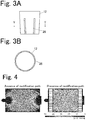
- the pin 12 has a plurality of grooves 26 on its outer peripheral surface.
- the outflow flow rate of the culture solution from the culture solution reservoir 4 is controlled by the pipeline resistance of the groove 26, and the relation of the following formula using the outflow flow rate as Q is established.
- n is the number of grooves 26
- L is the length of the groove 26
- ⁇ is the viscosity coefficient of the culture solution
- ⁇ is the density of the culture solution
- a is the length of one side of the flow path cross section
- g the gravitational acceleration
- h liquid surface height of the culture solution in the reservoir.
- Q n 1 48 a 4 L ⁇ ⁇ gh
- six grooves 26 having a length dimension of 5 mm, a thickness dimension of 0.35 mm, and a width dimension of 0.35 mm are provided.
- the flow rate Q becomes the maximum at 1.2 mL/min.
- the average flow velocity of the culture solution in the cell culture area 9 is about 0.16 mm/s, and the cells retained in the microwells do not be rolled up by the flow of the culture solution.
- the supply flow rate of the culture solution from the culture solution reservoir 4 is 2 mL/min or less, the cells retained in the microwell do not be rolled up.
- a mechanism for supplying the culture solution to the culture solution reservoir 4 at a constant flow rate may be provided so that the flow velocity of the culture solution flowing out from the culture solution reservoir 4 is constant.
- a mechanism for supplying the culture solution at a constant flow rate such as a liquid transfer pump 32 shown in Fig. 10 , may be provided, in place of the culture solution reservoir 4, and the culture solution may be directly supplied from this mechanism into the storage container 5 at a constant flow rate.
- a discharge unit 13 is provided at the end portion on the other end side (right side in the figures) of the frame 2, and the waste liquid reservoir 24 is provided below the discharge unit 13.
- the discharge unit 13 has a discharge flow path 14 therein extending vertically downward.
- An opening 14a at the upper end of the discharge flow path 14 forms a discharge port for discharging the culture solution in the storage container 5 through the discharge flow path 14.
- the opening 14a at the upper end of the discharge flow path 14 is called as "discharge port 14a".
- a peripheral edge portion 16 of the discharge port 14a raises more than its surroundings and forms a weir for maintaining the liquid surface height of the culture solution in the storage container 5 at a constant height.
- the peripheral edge portion 16 of the discharge port 14a is called as a "weir 16".
- the discharge unit 13 discharges only the culture solution flowing over the weir 16 to the waste liquid reservoir 24 through the discharge flow path 14.
- the discharge flow path 14 has a capillary portion 14b and an enlarged portion 14c.
- the upper end of the capillary portion 14b communicates with the discharge port 14a.
- the weir 16 around the discharge port 14a has a circular pipe shape and has a tapered shape which does not have a flat surface at its upper end so that the outer diameter of the upper end portion is substantially the same as inner diameter ⁇ 1 of the discharge port 14a.
- the Laplace pressure generated in the culture solution flowing over the weir 16 decreases, and as shown in Fig. 6A , although the culture solution rises on the weir 16, the liquid surface height becomes small as compared to the case of a plate-like weir 28 as shown in Figs. 7A to 7C .
- L1 is, for example, 2 mm.
- the capillary portion 14a of the discharge flow path 14 is formed to have an inner diameter such that the liquid is drawn into the inside by capillary force.
- the inner diameter of the capillary portion 14a is larger as it goes downward so that the culture solution drawn inside is less likely to clog in the middle.
- the inner diameter of the discharge port 14a is, for example, 1.1 mm.
- Length L2 of the capillary portion 14b is designed so that the gravity of the culture solution in the capillary portion 14b is larger than the Laplace pressure generated on the liquid surface formed at the lower end of the capillary portion 14b. While the culture solution drawn into the capillary portion 14b tries to stay in the capillary portion 14b due to the Laplace pressure generated on the liquid surface at the lower end, the Laplace pressure cannot withstand the gravity of the culture solution in the capillary portion 14b and drops, then the culture solution is less likely to clog in the capillary portion 14b.
- L2 is, for example, 8 mm.
- An enlarged portion 14c is provided below the capillary portion 14a.
- Inner diameter ⁇ 2 of an opening portion is set such that the lower part of the enlarged portion 14c opens and the Laplace pressure generated on the liquid surface of the culture solution formed in the opening is smaller than the water pressure of the culture solution in the enlarged portion 14c. That is, when the opening area of the lower end portion of the discharge flow path 14 is increased, as shown in Fig. 6C , the surface curvature of the liquid surface of the culture solution formed therein also becomes small, and the Laplace pressure generated on the liquid surface also becomes small.
- ⁇ 2 is, for example, 4.8 mm.
- the weir breaks down, the culture solution flows out and the liquid surface height drops, and when the liquid surface reaches the height of the weir 28, the outflow stops. Then, once the outflow of the culture solution stops, the culture solution is blocked again by the Laplace pressure at the edge of the weir 28, and when the liquid surface height rises to reach a certain height (L1 + ⁇ ), the weir breaks down.
- the cell culture container according to the present invention also includes a cell culture container 1a as shown in Figs. 7A to 7C , and since the planar shape of the weir 28 of the cell culture container 1a is linear, relatively large Laplace pressure is generated on the liquid surface of the culture solution at the edge of the weir 28 and height ⁇ of the liquid surface which is higher than the weir 28 increases.
- the weir 16 in the cell culture container 1 described with reference to Figs. 1 to 6C has a circular pipe shape and no flat surface is present at the upper end thereof, the Laplace pressure becomes smaller than the linear weir 28.
- the required liquid surface rise height ⁇ decreases until the weir 16 breaks down and the culture solution is drawn into the discharge flow path 14, the outflow cycle of the culture solution is discharged to the waste liquid reservoir 24 is shortened, and the flow of the culture solution in the cell culture area 9 also becomes continuous. Therefore, replacement of the culture solution in the cell culture area 9 can be stably performed.
- the curvature 1/R 2 of the section when the liquid surface is cut in the horizontal direction should be minus. Therefore, for example, the planar shape of the weir 1a of the cell culture container 1a in Figs. 7A to 7C may have a curved portion protruding toward the cell culture area 9 side.
- the frame 2 includes an opening portion 18 for sucking the old culture solution in the waste liquid reservoir 24 by a suction nozzle, at a position above the waste liquid reservoir 24 and different from the discharge unit 13.
- a suction nozzle for sucking the old culture solution in the waste liquid reservoir 24 by a suction nozzle, at a position above the waste liquid reservoir 24 and different from the discharge unit 13.
- a rectification path 20 for uniformizing the flow velocity of the culture solution flowing out of the pin 12 on one end side (left side in the figures) from the cell culture area 9 of the storage container 5 in the plane of the cell culture area 9 is provided.
- the rectification path 20 is a path in which a plurality of flow paths parallel to the flow direction (the left-right direction in the figures) of the culture solution flowing from the pin 12 toward the discharge unit 13 are uniformly arranged in a direction perpendicular to the flow direction of the culture solution in the horizontal plane (a vertical direction in Fig. 1 , a direction perpendicular to the paper surface in Fig. 2 ).
- the rectification path 20 was constituted by 22 flow paths, and each flow path had a width of 2 mm, a height of 0.5 mm, and a length of 10 mm.
- a rectification path 22 having the same configuration as the rectification path 20 is provided. Simulation results of the rectification effect of these rectification paths 20, 22 are shown in Fig. 4 .
- This simulation was performed using physical simulation software COMSOL Multiphysics.
- the flow velocity of the culture solution is fast near the pin 12 and near the discharge unit 13, and the distribution largely varies within the plane.
- the in-plane flow velocity distribution became uniform except for the vicinity of the upstream end and the downstream end of the cell culture area 9.
- the in-plane flow velocity distribution becomes uniform, the old culture solution is unlikely to be left behind, so that it is possible to replace more old culture solution with equal amounts of new culture solution.
- the culture solution in the storage container 5 takes the flow velocity distribution that it is the fastest in the vicinity of the liquid surface and the slowest in the vicinity of the bottom surface.
- This relative flow velocity distribution itself does not depend on the average flow velocity.
- the average flow velocity is fast (for example, 10 mL/min or more)
- the old culture solution is immediately replaced with a new culture solution in the vicinity of the liquid surface, but almost no flow occurs in the vicinity of the bottom surface, so that the old culture solution is left behind. Therefore, the amount of old culture solution to be removed is small relative to the amount of new culture solution flowing into the cell culture area 9. Therefore, only when the culture solution is flowed in one direction, the old culture solution stagnates on the deep layer side, and it is difficult to efficiently replace the old culture solution in the vicinity of the cells retained in the well with a new culture solution.
- each flow path forming the rectification path 20 blocks the culture solution on the surface layer side and flows only on the deep layer side.
- the rectification path 20 By supplying a new culture solution from the deep layer side to the cell culture area 9 by the rectification path 20, replacement of the older culture solution on the deep layer side is also promoted.
- the flow rate of the new culture solution supplied to the storage container 5 through the pin 12 is very small as 1.2 mL/min at the maximum. Due to this delay in average flow velocity, a new mobile phase flowing on the surface layer side and an old culture solution existing near the bottom surface are mixed by molecular diffusion, and more old culture solution is replaced.
- a plurality of outflow ports through which the culture solution of the culture solution reservoir 4 flows out are uniformly arranged in a direction perpendicular to the flow direction of the culture solution (a vertical direction in Fig. 1 ), whereby it is possible to obtain the same effect as in the case where the rectification path 20 is provided.
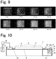
- Fig. 9 is images extracting only a G (green) channel out of RGB from the photographed images taken by a single lens reflex camera from the upper side while irradiating the cell culture area during experiment with light from the lower side of the plate with the LED surface light source.
- the shutter speed was 1/20 seconds, and the aperture was F22.
- red rhodamine B appears black.
- the culture solution in the culture solution reservoir 4 flows out of the culture solution reservoir 4 by its own weight, and flows into the cell culture area 9 with a gentle flow rate so as not to wind up the cells contained in each well of the cell culture area 9. Then, the new culture solution flowing into the cell culture area 9 pushes the old culture solution to the discharge unit 13 side, and the old culture solution is discharged to the waste liquid reservoir 24 through the discharge flow path 14. As a result, the replacement work of the culture solution becomes very simple, and at the same time, it is also possible to replace the culture solution of a plurality of cell culture containers.
Landscapes
- Chemical & Material Sciences (AREA)
- Health & Medical Sciences (AREA)
- Life Sciences & Earth Sciences (AREA)
- Engineering & Computer Science (AREA)
- Organic Chemistry (AREA)
- Zoology (AREA)
- Bioinformatics & Cheminformatics (AREA)
- Wood Science & Technology (AREA)
- Biomedical Technology (AREA)
- General Health & Medical Sciences (AREA)
- Sustainable Development (AREA)
- Biochemistry (AREA)
- General Engineering & Computer Science (AREA)
- Biotechnology (AREA)
- Genetics & Genomics (AREA)
- Microbiology (AREA)
- Analytical Chemistry (AREA)
- Dispersion Chemistry (AREA)
- Clinical Laboratory Science (AREA)
- Cell Biology (AREA)
- Virology (AREA)
- Apparatus Associated With Microorganisms And Enzymes (AREA)
Abstract
Description
- The present invention relates to a cell culture container in which a well for culturing cells is provided therein, and the well is immersed in a culture solution to culture a cell cluster.
- A cell culture plate in which microwells (hereinafter simply called as wells) for culturing a cell cluster are formed in a plate has been proposed and put to practical use. As a cell culture plate, in addition to a single hole plate, there are multiwell plates having a plurality of wells such as 6 holes or 24 holes (see, for example,
Patent Document 1 and Patent Document 2). In addition, there are cell culture plates with various wells of shape and size, such as circular wells and square wells, those with which wells are communicated, and those with through-holes at the bottom of wells. - When culturing a cell cluster using such a cell culture plate, the cell culture plate is placed at the bottom of a container (storage container) for storing a culture solution for culturing cells, and the cells are seeded in each well. The cells seeded in each well settle in the microwells and form a cluster in each well. By using a cell culture plate provided with a plurality of wells having uniform size, it is possible to efficiently prepare a cell cluster having uniform size.
-
- Patent Document 1: Japanese Patent Laid-open Publication No.
2010-022275 - Patent Document 2: Japanese Patent Laid-open Publication No.
2014-147342 - When culturing a cell cluster on a cell culture plate, it is necessary to replace the culture solution in the storage container. In replacement of the culture solution, it is common to manually perform the operation of firstly inclining the storage container with respect to the culture solution in the storage container or sucking it with a nozzle and then injecting the new culture solution into the storage container.
- However, since there is a problem that the cell cluster collapses due to the flow of the culture solution at the time of injection of the culture solution, or comes out of the wells, it is necessary to inject the culture solution into the storage container at a constant and slow flow velocity. Furthermore, there is a problem that the cell cluster is removed from the well together with the old culture solution when the culture solution is discarded. Therefore, it is necessary to slowly and carefully perform replacement of the culture solution, and it takes a long time to replace the culture solution, thus there has been a problem that it is difficult to culture a large amount of cell cluster on many cell culture plates at the same time.
- Thus, an object of the present invention is to facilitate replacement of a culture solution.
- A cell culture container according to the present invention includes a storage container, a cell culture area, a culture solution supply unit, a discharge unit, and a rectification unit. The storage container stores a culture solution. The cell culture area is an area provided in a storage container for culturing cells. The culture solution supply unit supplies a culture solution to the cell culture area at a flow rate equal to or less than a predetermined flow rate. The discharge unit discharges the culture solution in the culture area to the outside of the storage container. In the rectification unit, a plurality of outflow ports are uniformly arranged in a direction perpendicular to the flow direction of the culture solution from the culture solution supply unit to the discharge unit.
- The culture container may be an airtight container specified in the Japanese Pharmacopoeia. More specifically, it is a container that prevents infiltration of solids and liquids during normal handling, transportation and storage, and the outflow of the contents, and is a container that ensures ventilation for culturing. This makes it possible to maintain a safe culture environment more easily at the time of culture, open the airtight container only at the initial stage of replacement of the medium, remove the waste medium, and add fresh medium.
- If necessary, it may be a sealed container specified in the Japanese Pharmacopoeia. When replacing the medium in the sealed container, it is further preferable to create a communication path so as not to cause an imbalance in pressure due to a change in the liquid amount of the culture solution supply unit or the discharge unit, or perform treatment such as opening the sealed container and flowing a gas.
- Here, the "predetermined flow rate" that is the culture solution supply flow rate of the culture solution supply unit refers to a flow rate in which the cells retained in the cell culture area are not rolled up or flowed by the flow of the culture solution, and a laminar flow is generated in the cell culture area. Such a flow rate is, for example, a flow rate of 2 mL/min or less.
- The discharge unit preferably has a discharge port for discharging a liquid in the storage container to the outside of the storage container and a weir provided higher than the height of the upper surface of the cell culture unit in the cell culture area, and is configured so that only a liquid that flows over the weir is guided to the discharge port. Then, while the liquid surface height of the culture solution in the culture solution supply unit is maintained higher than the height of the upper surface of the cell culture unit, the old culture solution swept away by the new culture solution supplied to the cell culture area by the culture solution supply unit is automatically discarded from the discharge port to the outside of the storage container. By these actions, replacement work of the culture solution in the storage container is facilitated, and it is possible to prevent the cells retained in the cell culture area from getting out of the wells or being discarded together with the old culture solution.
- The culture solution supply unit may have a culture solution reservoir for storing a culture solution above the storage container and supply the culture solution stored in the culture solution reservoir by the own weight of the culture solution in the culture solution reservoir. Then, the configuration of the cell culture container can be simplified. Then, simply by placing a culture solution in the culture solution reservoir, the culture solution is automatically supplied into the storage container at a flow rate equal to or less than the predetermined flow rate by the own weight of the culture solution in the culture solution reservoir, so that the replacement work of the culture solution is facilitated.
- Incidentally, when the culture solution flows over the weir, the culture solution rises at the upper end of the weir due to the surface tension of the culture solution, and the liquid surface height of the culture solution becomes higher than the height of the weir. This is because when the culture solution rises at the upper end of the weir, a pressure difference called Laplace pressure is generated across the liquid surface of the culture solution, and when the Laplace pressure cannot support the mass of the culture solution, the weir breaks down and the culture solution flows over the weir.
- The magnitude of the Laplace pressure ΔP generated in the culture solution is expressed as the product of the surface tension and the surface curvature of the liquid surface at that point, as shown in the formula (1). The surface curvature is the sum of the curvatures of the sections when the curved surface is cut in two directions orthogonal to each other. In the formula (1), γ is the surface tension and is a variable specific to the liquid. 1/R1 is the curvature of the section when the liquid surface is cut in the vertical direction, and 1/R2 is the curvature of the section when the liquid surface is cut in the horizontal direction.

- From the above formula (1), it is understood that the magnitude of the Laplace pressure ΔP varies depending on the planar shape of the weir. For example, in the case where the weir has a plate shape and the planar shape is linear, since the section of the liquid surface when cutting the culture solution raised in the weir shape in the horizontal direction is also a linear shape, 1/R2 is always 0. Therefore, the Laplace pressure ΔP is expressed as:

curvature 1/R1 increases. When the liquid surface protrudes to the downstream side of the weir and thecurvature 1/R1 takes the maximum value, the Laplace pressure ΔP loses the gravity and the dam breaks down, and the culture solution flows over the weir. - In addition, 1/R2 is always negative when the planar shape of the weir is curved in a convex shape in a direction opposite to the flow direction of the culture solution, and the Laplace pressure ΔP becomes small as compared to the case where the planar shape of the weir is linear. As the Laplace pressure ΔP decreases, the liquid surface height of the culture solution rising on the weir also becomes lower, thus the culture solution easily flows over the weir to be guided to the discharge flow path. As the culture solution easily flows over the weir to be guided to the discharge flow path, the old culture solution is smoothly discarded through the discharge flow path, thus the replacement of the culture solution in the storage container can be smoothly performed.
- From the above, in the cell culture container according to the present invention, it is preferable that the weir provided in the discharge unit has a portion in which the planar shape at the top end is curved in a convex shape toward the cell culture area side. The fact that the planar shape of the weir has a portion curved in a convex shape toward the cell culture area side means that a portion that "is curved in a convex shape in a direction opposite to the flow direction of the culture solution" is provided on the planar shape of the weir. The culture solution passes through the cell culture area and reaches the discharge unit. Therefore, in the portion of the weir in which the planar shape is curved in a convex shape toward the cell culture area side, the Laplace pressure ΔP becomes smaller than in the case where the planar shape of the weir is linear, the culture solution easily flows over the weir to be guided to the discharge flow path. As a result, the replacement of the culture solution in the storage container is smoothly performed.
- Example of a preferred embodiment of the above case include an embodiment in which the planar shape of the weir is an annular shape, and the discharge port is provided inside the weir. That is, at least the upper end portion of the weir has a circular pipe shape. When the
curvature 1/R2 at an arbitrary point of the culture solution going to flow over the weir is D, the radius of curvature of the weir is D, and the horizontal distance from the edge of the opening of the weir upper end at that point is r, it can be expressed as:

- In the case where the planar shape of the weir is formed into an annular shape, it is preferable that the discharge port is an upper end of a downwardly extending discharge flow path, the discharge flow path has a capillary portion having an inner diameter of 2 mm or less and a hydrophilic inner surface, and the capillary portion communicates with the discharge port. Then, the culture solution flowing over the weir is drawn into the discharge flow path by capillary force, so that the old culture solution can be discarded more smoothly.
- Furthermore, a waste liquid reservoir for receiving the liquid discharged to the outside of the storage container through the discharge flow path is provided below the storage container, and when the discharge flow path extends vertically downward from the inside of the storage container and drips the waste liquid to the waste liquid reservoir, it is preferable that the inner diameter of the capillary portion increases as it goes downward. When the inner diameter of the capillary portion of the discharge flow path is small, it is considered that the liquid is likely to stay in the capillary portion and the culture solution cannot be discarded smoothly. Such an inconvenience can be alleviated by increasing the inner diameter of the capillary portion of the discharge flow path as it goes downward.
- In addition, a droplet of the culture solution is formed at the lower end of the discharge flow path, and when the outer diameter of the droplet is small, the Laplace pressure generated in the droplet becomes large, and the culture solution is less likely to be dropped from the discharge flow path to the waste liquid reservoir. Therefore, it is preferable that the length and the inner diameter of the lower end of the capillary portion are set so that the Laplace pressure generated on the liquid surface formed at the lower end of the capillary portion is smaller than the gravity of the liquid in the capillary portion. Then, the culture solution drawn into the capillary portion is likely to descend by the own weight, and it is possible to prevent the culture solution from clogging in the capillary portion.
- The discharge flow path preferably has, below the capillary portion, an enlarged portion having an inner diameter larger than the inner diameter of the lower end of the capillary portion and having an open lower portion. Then, the outer diameter of the liquid surface formed at the downstream end of the discharge flow path becomes large, and the Laplace pressure generated on the liquid surface of the culture solution at the lower end of the discharge flow path decreases. As a result, the culture solution is likely to be dropped from the lower end of the discharge flow path to the waste liquid reservoir, and discard of the culture solution is promoted.
- It is preferable that a cross section of the upper end portion of the weir has an acute angle shape converging upward, that is, there is no flat surface at the upper end portion of the weir, and the outer diameter of the upper end portion of the weir is very close to the inner diameter of the inside thereof. As a result, the culture solution is less likely to rise on the weir, and the discard of the culture solution is more smoothed. Further, by setting the outer diameter of the weir upper end portion closer to its inner diameter to 2.5 mm or less, the Laplace pressure ΔP can be reduced, and when the liquid surface attempts to protrude inward from the edge of the weir, the liquid surfaces come into contact with each other on the weir and flow into the discharge flow path, so that the maximum value that 1/R1 in the formula (4) can take becomes even smaller, and the discard of the culture solution flowing over the weir is more smoothed.
- Also, examples of a preferred embodiment of the rectification unit include those including a rectification path in which a plurality of flow paths parallel to a solvent flow direction from a culture solution supply unit side to a discharge unit side of the cell culture area are uniformly arranged in a direction perpendicular to the solvent flow direction in the horizontal plane.
- The new culture solution supplied to the storage container is likely to flow on the surface layer side of the culture solution stored in the storage container, and the culture solution located on the bottom surface side of the storage container is less likely to be replaced while the culture solution on the surface layer side is replaced. Therefore, it is preferable that each of the flow paths constituting the rectification path is configured to block the liquid on the surface layer side in the storage container and pass the liquid on the bottom layer side of the storage container. Then, since the new culture solution is supplied from the vicinity of the bottom surface of the storage container to the cell culture area, the culture solution located on the bottom surface side of the storage container is also likely to be replaced.
- Since the cell culture container according to the present invention includes a culture solution supply unit for supplying a culture solution into a storage container from one end side of a cell culture area at a flow rate equal to or less than a predetermined flow rate, it is possible to supply a new culture solution to the cell culture area at a flow rate equal to or less than a predetermined flow rate. Furthermore, since it has a rectification unit in which a plurality of outflow ports are uniformly arranged in a direction perpendicular to the flow direction of the culture solution from the culture solution supply unit to a discharge unit, the flow velocity distribution of a new culture solution supplied by the culture solution supply unit in the plane of the cell culture area becomes uniform, and the culture solution in the entire cell culture area can be easily and uniformly replaced with the new culture solution.
-
-
Fig. 1 is a plan view showing an embodiment of a cell culture container. -
Fig. 2 is a cross-sectional view taken along line X-X ofFig. 1 . -
Fig. 3A is a front view showing a structure of a culture solution supply unit of the same embodiment. -
Fig. 3B is a cross-sectional view taken along line Y-Y ofFig. 3A . -
Fig. 4 is a view showing a result of examination of rectification effect by a rectification path. The diagram on the left side is a flow velocity distribution diagram in the case where a rectification path is not provided, and the diagram on the right side is a flow velocity distribution diagram in the case where a rectification path is provided. -
Fig. 5 is a cross-sectional view for explaining a structure of a discharge unit of the same embodiment. -
Fig. 6A is a cross-sectional view showing a state in which a culture solution rises on a weir of a discharge unit. -
Fig. 6B is a cross-sectional view showing a state in which a culture solution is drawn into a capillary portion of a discharge flow path. -
Fig. 6C is a cross-sectional view showing a state in which a culture solution reaches an enlarged portion of a discharge flow path. -
Fig. 7A is a plan view showing another embodiment of a cell culture container. -
Fig. 7B is a cross-sectional view taken along line Z-Z ofFig. 7A . -
Fig. 7C is a cross-sectional view showing a state in which a culture solution rises on a weir of a discharge unit. -
Fig. 8A is a graph showing an example of temporal change in liquid surface height in a storage container when a weir of a discharge unit is formed into a plate shape. -
Fig. 8B is a graph showing an example of temporal change in liquid surface height in a storage container when a weir of a discharge unit is formed in a circular tube shape. -
Fig. 9 is an image diagram showing a replacement state of a culture solution in a storage container for each elapsed time. -
Fig. 10 is a plan view showing another embodiment of a cell culture container. - An embodiment of a cell culture device according to the present invention will be described with reference to the drawings.
- As shown in
Figs. 1 and 2 , acell culture container 1 includes aframe 2, aculture solution reservoir 4, adimple membrane 8, and awaste liquid reservoir 24. Thedimple membrane 8 is a member on the plate, and a plurality of microwells for culturing cells are arranged on one side. Thedimple membrane 8 is attached to theframe 2 in a state where the surface on the side where the microwells are arranged is on the upper side. -
Side walls frame 2, and thedimple membrane 8 attached to theframe 2 and theside walls storage container 5 of a culture solution with thedimple membrane 8 as the bottom surface. Thedimple membrane 8 has microwells in a plane between arectification path 20 and arectification path 22, which will be described later. In thestorage container 5 formed by thedimple membrane 8 and theside walls dimple membrane 8 surrounded by a broken line where the microwells are arranged is called as acell culture area 9. - In this embodiment, the
cell culture area 9 has a rectangular shape, but it may have a circular shape, an oval shape or another shape. In addition, in this embodiment, a plurality of microwells are arranged in thecell culture area 9, but the wells are not necessarily need to be arranged, as long as they can be cultured by retaining cells. - In this embodiment, the upper surface of the
storage container 5 is opened, but the upper surface of thestorage container 5 does not necessarily need to be opened, and may be sealed to be an airtight container. This makes it possible to maintain a safe culture environment more easily at the time of culture, open the airtight container only at the initial stage of replacement of the medium, remove the waste medium, and add fresh medium. - The
culture solution reservoir 4 is attached to the upper surface of the end portion on one end side (left side in the figures) of theframe 2. Theculture solution reservoir 4 is a container with an open top, and apin 12 protruding downward is provided on the bottom surface thereof. Theculture solution reservoir 4 and thepin 12 constitute a culture solution supply unit for supplying a new culture solution to thecell culture area 9 at a flow rate equal to or less than a predetermined flow rate. - As shown in
Figs. 3A and 3B , thepin 12 has a plurality ofgrooves 26 on its outer peripheral surface. The outflow flow rate of the culture solution from theculture solution reservoir 4 is controlled by the pipeline resistance of thegroove 26, and the relation of the following formula using the outflow flow rate as Q is established. Here, n is the number ofgrooves 26, L is the length of thegroove 26, µ is the viscosity coefficient of the culture solution, ρ is the density of the culture solution, a is the length of one side of the flow path cross section, g is the gravitational acceleration, and h is the liquid surface height of the culture solution in the reservoir.
- In this embodiment, six
grooves 26 having a length dimension of 5 mm, a thickness dimension of 0.35 mm, and a width dimension of 0.35 mm are provided. In this case, when the culture solution is accumulated up to the upper end of the culture solution reservoir 4 (the height from the bottom surface is 15 mm), the flow rate Q becomes the maximum at 1.2 mL/min. With this flow rate, the average flow velocity of the culture solution in thecell culture area 9 is about 0.16 mm/s, and the cells retained in the microwells do not be rolled up by the flow of the culture solution. In the configuration of this embodiment, when the supply flow rate of the culture solution from theculture solution reservoir 4 is 2 mL/min or less, the cells retained in the microwell do not be rolled up. - Meanwhile, a mechanism for supplying the culture solution to the
culture solution reservoir 4 at a constant flow rate may be provided so that the flow velocity of the culture solution flowing out from theculture solution reservoir 4 is constant. Also, a mechanism for supplying the culture solution at a constant flow rate, such as aliquid transfer pump 32 shown inFig. 10 , may be provided, in place of theculture solution reservoir 4, and the culture solution may be directly supplied from this mechanism into thestorage container 5 at a constant flow rate. - Referring back to
Figs. 1 and 2 , adischarge unit 13 is provided at the end portion on the other end side (right side in the figures) of theframe 2, and thewaste liquid reservoir 24 is provided below thedischarge unit 13. Thedischarge unit 13 has adischarge flow path 14 therein extending vertically downward. Anopening 14a at the upper end of thedischarge flow path 14 forms a discharge port for discharging the culture solution in thestorage container 5 through thedischarge flow path 14. Hereinafter, theopening 14a at the upper end of thedischarge flow path 14 is called as "discharge port 14a". Aperipheral edge portion 16 of thedischarge port 14a raises more than its surroundings and forms a weir for maintaining the liquid surface height of the culture solution in thestorage container 5 at a constant height. Hereinafter, theperipheral edge portion 16 of thedischarge port 14a is called as a "weir 16". Thedischarge unit 13 discharges only the culture solution flowing over theweir 16 to thewaste liquid reservoir 24 through thedischarge flow path 14. - As shown in
Fig. 5 , thedischarge flow path 14 has acapillary portion 14b and anenlarged portion 14c. The upper end of thecapillary portion 14b communicates with thedischarge port 14a. Theweir 16 around thedischarge port 14a has a circular pipe shape and has a tapered shape which does not have a flat surface at its upper end so that the outer diameter of the upper end portion is substantially the same as inner diameter φ1 of thedischarge port 14a. As a result, the Laplace pressure generated in the culture solution flowing over theweir 16 decreases, and as shown inFig. 6A , although the culture solution rises on theweir 16, the liquid surface height becomes small as compared to the case of a plate-like weir 28 as shown inFigs. 7A to 7C . As a result, the culture solution exceeding the height L1 of theweir 16 from the surface of thedimple membrane 8 is easily discharged through thedischarge flow path 14b. L1 is, for example, 2 mm. - Further, the
capillary portion 14a of thedischarge flow path 14 is formed to have an inner diameter such that the liquid is drawn into the inside by capillary force. As a result, when the culture solution faces thedischarge port 14a, as shown inFig. 6B , the culture solution is drawn into thecapillary portion 14a by capillary force. The inner diameter of thecapillary portion 14a is larger as it goes downward so that the culture solution drawn inside is less likely to clog in the middle. The inner diameter of thedischarge port 14a is, for example, 1.1 mm. - Length L2 of the
capillary portion 14b is designed so that the gravity of the culture solution in thecapillary portion 14b is larger than the Laplace pressure generated on the liquid surface formed at the lower end of thecapillary portion 14b. While the culture solution drawn into thecapillary portion 14b tries to stay in thecapillary portion 14b due to the Laplace pressure generated on the liquid surface at the lower end, the Laplace pressure cannot withstand the gravity of the culture solution in thecapillary portion 14b and drops, then the culture solution is less likely to clog in thecapillary portion 14b. L2 is, for example, 8 mm. - An
enlarged portion 14c is provided below thecapillary portion 14a. Inner diameter φ2 of an opening portion is set such that the lower part of theenlarged portion 14c opens and the Laplace pressure generated on the liquid surface of the culture solution formed in the opening is smaller than the water pressure of the culture solution in theenlarged portion 14c. That is, when the opening area of the lower end portion of thedischarge flow path 14 is increased, as shown inFig. 6C , the surface curvature of the liquid surface of the culture solution formed therein also becomes small, and the Laplace pressure generated on the liquid surface also becomes small. φ2 is, for example, 4.8 mm. - As a result, when the liquid surface of the culture solution in the
storage container 5 exceeds theweir 16, the culture solution is smoothly discharged to thewaste liquid reservoir 24 through thedischarge flow path 14, and the culture solution can be stably replaced. - Here, as shown in
Figs. 7A to 7C , when theweir 28 for maintaining the liquid surface height of the culture solution in thestorage container 5 constant is provided, and adischarge port 30 for guiding the culture solution flowing over theweir 28 to thewaste liquid reservoir 24 is provided on the downstream side of theweir 28, as shown inFig. 8A , outflow of the culture solution intermittently occurs, due to the Laplace pressure generated on the liquid surface when the culture solution flows over theweir 28. That is, even when the liquid surface height of the culture solution reaches the height (L1) of theweir 28, the culture solution rises at the edge of theweir 28 due to the Laplace pressure by surface amount force and the liquid surface rises. When the Laplace pressure cannot withstand the water pressure of the culture solution, the weir breaks down, the culture solution flows out and the liquid surface height drops, and when the liquid surface reaches the height of theweir 28, the outflow stops. Then, once the outflow of the culture solution stops, the culture solution is blocked again by the Laplace pressure at the edge of theweir 28, and when the liquid surface height rises to reach a certain height (L1 + α), the weir breaks down. - The cell culture container according to the present invention also includes a
cell culture container 1a as shown inFigs. 7A to 7C , and since the planar shape of theweir 28 of thecell culture container 1a is linear, relatively large Laplace pressure is generated on the liquid surface of the culture solution at the edge of theweir 28 and height α of the liquid surface which is higher than theweir 28 increases. - In contrast, since the
weir 16 in thecell culture container 1 described with reference toFigs. 1 to 6C has a circular pipe shape and no flat surface is present at the upper end thereof, the Laplace pressure becomes smaller than thelinear weir 28. As a result, as shown inFig. 8B , the required liquid surface rise height α decreases until theweir 16 breaks down and the culture solution is drawn into thedischarge flow path 14, the outflow cycle of the culture solution is discharged to thewaste liquid reservoir 24 is shortened, and the flow of the culture solution in thecell culture area 9 also becomes continuous. Therefore, replacement of the culture solution in thecell culture area 9 can be stably performed. - As mentioned above, the Laplace pressure ΔP generated on the liquid surface when flowing over the weir is expressed as :

curvature 1/R2 of the section when the liquid surface is cut in the horizontal direction should be minus. Therefore, for example, the planar shape of theweir 1a of thecell culture container 1a inFigs. 7A to 7C may have a curved portion protruding toward thecell culture area 9 side. - Referring back to
Figs. 1 and 2 , theframe 2 includes an openingportion 18 for sucking the old culture solution in thewaste liquid reservoir 24 by a suction nozzle, at a position above thewaste liquid reservoir 24 and different from thedischarge unit 13. Thus, it is possible to collect the old culture solution without tilting thecell culture container 1 and removing thewaste liquid reservoir 24. - A
rectification path 20 for uniformizing the flow velocity of the culture solution flowing out of thepin 12 on one end side (left side in the figures) from thecell culture area 9 of thestorage container 5 in the plane of thecell culture area 9 is provided. Therectification path 20 is a path in which a plurality of flow paths parallel to the flow direction (the left-right direction in the figures) of the culture solution flowing from thepin 12 toward thedischarge unit 13 are uniformly arranged in a direction perpendicular to the flow direction of the culture solution in the horizontal plane (a vertical direction inFig. 1 , a direction perpendicular to the paper surface inFig. 2 ). In this embodiment, therectification path 20 was constituted by 22 flow paths, and each flow path had a width of 2 mm, a height of 0.5 mm, and a length of 10 mm. - Also on the other end side (right side in the figures) of the
cell culture area 9 of thestorage container 5, arectification path 22 having the same configuration as therectification path 20 is provided. Simulation results of the rectification effect of theserectification paths Fig. 4 . This simulation was performed using physical simulation software COMSOL Multiphysics. As shown inFig. 4 , in the absence of therectification paths pin 12 and near thedischarge unit 13, and the distribution largely varies within the plane. On the other hand, when therectification paths cell culture area 9. When the in-plane flow velocity distribution becomes uniform, the old culture solution is unlikely to be left behind, so that it is possible to replace more old culture solution with equal amounts of new culture solution. - In addition, the culture solution in the
storage container 5 takes the flow velocity distribution that it is the fastest in the vicinity of the liquid surface and the slowest in the vicinity of the bottom surface. This relative flow velocity distribution itself does not depend on the average flow velocity. In the case where the average flow velocity is fast (for example, 10 mL/min or more), the old culture solution is immediately replaced with a new culture solution in the vicinity of the liquid surface, but almost no flow occurs in the vicinity of the bottom surface, so that the old culture solution is left behind. Therefore, the amount of old culture solution to be removed is small relative to the amount of new culture solution flowing into thecell culture area 9. Therefore, only when the culture solution is flowed in one direction, the old culture solution stagnates on the deep layer side, and it is difficult to efficiently replace the old culture solution in the vicinity of the cells retained in the well with a new culture solution. - On the other hand, each flow path forming the
rectification path 20 blocks the culture solution on the surface layer side and flows only on the deep layer side. By supplying a new culture solution from the deep layer side to thecell culture area 9 by therectification path 20, replacement of the older culture solution on the deep layer side is also promoted. - Further, the flow rate of the new culture solution supplied to the
storage container 5 through thepin 12 is very small as 1.2 mL/min at the maximum. Due to this delay in average flow velocity, a new mobile phase flowing on the surface layer side and an old culture solution existing near the bottom surface are mixed by molecular diffusion, and more old culture solution is replaced. - In addition, even when the
rectification path 20 is not provided, a plurality of outflow ports through which the culture solution of theculture solution reservoir 4 flows out are uniformly arranged in a direction perpendicular to the flow direction of the culture solution (a vertical direction inFig. 1 ), whereby it is possible to obtain the same effect as in the case where therectification path 20 is provided. - Next, the results of experiments conducted on replacement of the culture solution using the
cell culture container 1 will be described with reference toFig. 9 . In this experiment, using an aqueous dye solution as an alternative to the old culture solution, and using water as an alternative to the new culture solution, rhodamine B (Sigma-Aldrich Corporation) was used as a dye. The state in which the rhodamine B aqueous solution in thecell culture area 9 was replaced with water flowing out of theculture solution reservoir 4 was observed. - The water poured into the reservoir at
time 0 seconds flowed into thecell culture area 9 over about 800 seconds, and the rhodamine aqueous solution was accumulated in thewaste liquid reservoir 24.Fig. 9 is images extracting only a G (green) channel out of RGB from the photographed images taken by a single lens reflex camera from the upper side while irradiating the cell culture area during experiment with light from the lower side of the plate with the LED surface light source. The shutter speed was 1/20 seconds, and the aperture was F22. On the G channel image, red rhodamine B appears black. - From these images, it can be confirmed that the rhodamine B aqueous solution in the cell culture area is replaced with water from the
culture solution reservoir 4, whereby the black color gradually pales. - In this manner, in the
cell culture container 1 described above, simply by adding a necessary amount of a new culture solution to theculture solution reservoir 4, the culture solution in theculture solution reservoir 4 flows out of theculture solution reservoir 4 by its own weight, and flows into thecell culture area 9 with a gentle flow rate so as not to wind up the cells contained in each well of thecell culture area 9. Then, the new culture solution flowing into thecell culture area 9 pushes the old culture solution to thedischarge unit 13 side, and the old culture solution is discharged to thewaste liquid reservoir 24 through thedischarge flow path 14. As a result, the replacement work of the culture solution becomes very simple, and at the same time, it is also possible to replace the culture solution of a plurality of cell culture containers. -
- 1, 1a:
- Cell culture container
- 2:
- Frame
- 4:
- Culture solution reservoir
- 6, 10, 11:
- Side wall
- 8:
- Dimple membrane
- 9:
- Cell culture area
- 12:
- Pin
- 13:
- Discharge unit
- 14:
- Discharge flow path
- 14a, 30:
- Discharge port
- 14b:
- Capillary portion
- 14c:
- Enlarged portion
- 16, 28:
- Weir
- 18:
- Opening portion
- 20, 22:
- Rectification path
- 24:
- Waste liquid reservoir
- 26:
- Groove
Claims (13)
- A cell culture container comprising
a storage container for storing a culture solution,
a cell culture area provided in the storage container for culturing cells,
a culture solution supply unit for supplying the culture solution to the cell culture area at a flow rate equal to or less than a predetermined flow rate,
a discharge unit for discharging the culture solution in the cell culture area to the outside of the storage container, and
a rectification unit in which a plurality of outflow ports are uniformly arranged in a direction perpendicular to the flow direction of the culture solution from the culture solution supply unit to the discharge unit. - The cell culture container according to claim 1, wherein the discharge unit has a discharge port for discharging a liquid in the storage container to the outside of the storage container and a weir provided higher than the height of the upper surface of the cell culture unit in the cell culture area, and is configured so that only a liquid that flows over the weir is guided to the discharge port.
- The cell culture container according to claim 1 or 2, wherein the culture solution supply unit has a culture solution reservoir for storing the culture solution above the storage container, and supplies the culture solution stored in the culture solution reservoir by the own weight of the culture solution in the culture solution reservoir.
- The cell culture container according to claim 1 or 2, wherein the culture solution supply unit supplies a culture solution into the storage container using a liquid transfer pump.
- The cell culture container according to any one of claims 1 to 4, wherein the weir has a portion in which a planar shape at an upper end is curved in a convex shape toward the cell culture area side.
- The cell culture container according to claim 5, wherein the planar shape of the weir is an annular shape, and the discharge port is provided inside the weir.
- The cell culture device according to claim 6, wherein the discharge port is an upper end of a downwardly extending discharge flow path,
the discharge flow path has a capillary portion having an inner diameter of 2 mm or less and a hydrophilic inner surface, and the capillary portion communicates with the discharge unit. - The cell culture container according to claim 7, wherein a waste liquid reservoir for receiving a liquid discharged to the outside of the storage container through the discharge flow path is provided below the storage container,
the discharge flow path extends vertically downward from the inside of the storage container and drips the waste liquid to the waste liquid reservoir, and the inner diameter of the capillary portion increases as it goes downward. - The cell culture container according to claim 8, wherein the length and the inner diameter of the lower end of the capillary portion are set so that the Laplace pressure generated on the liquid surface formed at the lower end of the capillary portion is smaller than the gravity of the liquid in the capillary portion.
- The cell culture container according to any one of claims 7 to 9, wherein the discharge flow path is provided with an enlarged portion having an inner diameter larger than the inner diameter of the lower end of the capillary portion below the capillary portion, and having an open lower portion.
- The cell culture container according to any one of claims 2 to 10, wherein a cross section of the upper end portion of the weir has an acute angle shape converging upward.
- The cell culture container according to any one of claims 1 to 11, wherein the rectification unit comprises a rectification path in which a plurality of flow paths parallel to a solvent flow direction from the culture solution supply unit side to the discharge unit side of the cell culture area are uniformly arranged in a direction perpendicular to the solvent flow direction in the horizontal plane.
- The cell culture container according to claim 12, wherein each of the flow paths constituting the rectification path is configured to block the liquid on the surface layer side and pass the liquid on the deep layer side.
Applications Claiming Priority (1)
| Application Number | Priority Date | Filing Date | Title |
|---|---|---|---|
| PCT/JP2016/058409 WO2017158777A1 (en) | 2016-03-16 | 2016-03-16 | Cell culture vessel |
Publications (2)
| Publication Number | Publication Date |
|---|---|
| EP3431578A1 true EP3431578A1 (en) | 2019-01-23 |
| EP3431578A4 EP3431578A4 (en) | 2019-11-27 |
Family
ID=59851492
Family Applications (1)
| Application Number | Title | Priority Date | Filing Date |
|---|---|---|---|
| EP16894395.9A Pending EP3431578A4 (en) | 2016-03-16 | 2016-03-16 | CONTAINER OF CELL CULTURE |
Country Status (5)
| Country | Link |
|---|---|
| US (1) | US11186810B2 (en) |
| EP (1) | EP3431578A4 (en) |
| JP (1) | JP6892580B2 (en) |
| CN (1) | CN109072167B (en) |
| WO (1) | WO2017158777A1 (en) |
Families Citing this family (2)
| Publication number | Priority date | Publication date | Assignee | Title |
|---|---|---|---|---|
| EP3561038A1 (en) * | 2018-04-24 | 2019-10-30 | Bayer AG | Cell separator |
| US11958050B2 (en) * | 2018-05-24 | 2024-04-16 | John Collins | Fluidic devices for closed cell culture applications under current good manufacturing practice |
Family Cites Families (14)
| Publication number | Priority date | Publication date | Assignee | Title |
|---|---|---|---|---|
| FR2499542A1 (en) * | 1981-02-09 | 1982-08-13 | Stephanois Constr Meca | Digester vessel to make methane from liq. manure - has overflow with upstream vertical leg to build head pressure to shift blockage |
| US5372712A (en) | 1993-02-25 | 1994-12-13 | Envirex Inc. | Biomass growth control apparatus for fluid bed biological reactor |
| TW264397B (en) * | 1994-02-14 | 1995-12-01 | Envirex | |
| US6566126B2 (en) * | 2001-06-22 | 2003-05-20 | Fibercell Systems, Inc. | Apparatus and method for growing cells |
| JP2006141326A (en) * | 2004-11-22 | 2006-06-08 | Hitachi Medical Corp | Culturing device |
| WO2006089354A1 (en) * | 2005-02-23 | 2006-08-31 | M.B.T.L. Limited | Culture device |
| JP2009273459A (en) * | 2008-04-15 | 2009-11-26 | Tosoh Corp | Cell selection apparatus, and cell selection method using the same |
| JP5148397B2 (en) | 2008-07-18 | 2013-02-20 | 株式会社クラレ | Cell culture container and cell culture method |
| CN103146572B (en) * | 2011-12-07 | 2016-01-06 | 清华大学 | A kind of apparatus and method realizing the growth of cell colony uniformity |
| CN202807433U (en) * | 2012-01-20 | 2013-03-20 | 安泰凯生物技术有限公司 | Sample holding device |
| EP2864469A4 (en) * | 2012-06-21 | 2016-05-18 | Neostem Oncology Llc | Bioreactor cartridge and system |
| JP6124051B2 (en) | 2013-02-01 | 2017-05-10 | 国立大学法人九州工業大学 | Cell culture sheet, method for producing the same, and cell culture container using the same |
| CN103966095B (en) * | 2014-05-22 | 2016-01-20 | 中国人民解放军第三军医大学第三附属医院 | A kind of bio-reactor being applicable to three-dimensional tissue's Cell infusion and cultivating |
| EP3147349B1 (en) * | 2014-05-22 | 2019-07-10 | The Third Affiliated Hospital of Third Military Medical University | Bioreactor for three-dimensional tissue perfusion culture |
-
2016
- 2016-03-16 CN CN201680083583.6A patent/CN109072167B/en active Active
- 2016-03-16 US US16/084,283 patent/US11186810B2/en active Active
- 2016-03-16 WO PCT/JP2016/058409 patent/WO2017158777A1/en not_active Ceased
- 2016-03-16 JP JP2018505152A patent/JP6892580B2/en active Active
- 2016-03-16 EP EP16894395.9A patent/EP3431578A4/en active Pending
Also Published As
| Publication number | Publication date |
|---|---|
| JPWO2017158777A1 (en) | 2018-12-27 |
| US11186810B2 (en) | 2021-11-30 |
| US20190078044A1 (en) | 2019-03-14 |
| JP6892580B2 (en) | 2021-06-23 |
| EP3431578A4 (en) | 2019-11-27 |
| CN109072167A (en) | 2018-12-21 |
| CN109072167B (en) | 2022-11-25 |
| WO2017158777A1 (en) | 2017-09-21 |
Similar Documents
| Publication | Publication Date | Title |
|---|---|---|
| TWI444473B (en) | Microfluidic hanging drop chip | |
| US20150114222A1 (en) | Micro fluid device and method of separating air bubbles in liquid | |
| US20160107159A1 (en) | Microfluidic device and method for controlling fluid flow thereinto | |
| CN101896215A (en) | piercing element with two pins | |
| US11186810B2 (en) | Cell culture vessel | |
| US10677811B2 (en) | Sample receptacle, sample container and method of use | |
| US20210060459A1 (en) | Filtration device and filtration method | |
| KR20160033026A (en) | Coating machine, coating device, and coating method | |
| JP4705439B2 (en) | Cell capture petri dish | |
| JP2020138380A (en) | Liquid container | |
| US20250224745A1 (en) | Technique for Small Volume Metering | |
| US20150224501A1 (en) | Fluid reservoir | |
| JPS5969756A (en) | Apparatus for treating contact liquid of photosensitive she-et material | |
| KR101141248B1 (en) | Microfluidic device for air bubble removal and fluid injection/removal | |
| US20250019636A1 (en) | Device for separating motile cells | |
| JP2009040425A (en) | Spout implement for bottle | |
| KR20250056952A (en) | Devices and systems for delivering a stream of liquid and apparatus and methods for non-immersion wet-chemical treatment of planar substrates | |
| CN213689140U (en) | Integrated kit | |
| KR102956723B1 (en) | Cell screening device and cell screening kit | |
| JP2016210425A (en) | Dropper lid for viscous fluid discharge device | |
| JP5931202B2 (en) | Individual input hopper | |
| JP2008238045A (en) | Bubble removing apparatus | |
| US20240316863A1 (en) | Printhead with internal microfluidic channels | |
| CN113959819B (en) | All-in-one kit | |
| JP4528330B2 (en) | Micropump and microfluidic chip |
Legal Events
| Date | Code | Title | Description |
|---|---|---|---|
| STAA | Information on the status of an ep patent application or granted ep patent |
Free format text: STATUS: THE INTERNATIONAL PUBLICATION HAS BEEN MADE |
|
| PUAI | Public reference made under article 153(3) epc to a published international application that has entered the european phase |
Free format text: ORIGINAL CODE: 0009012 |
|
| STAA | Information on the status of an ep patent application or granted ep patent |
Free format text: STATUS: REQUEST FOR EXAMINATION WAS MADE |
|
| 17P | Request for examination filed |
Effective date: 20181011 |
|
| AK | Designated contracting states |
Kind code of ref document: A1 Designated state(s): AL AT BE BG CH CY CZ DE DK EE ES FI FR GB GR HR HU IE IS IT LI LT LU LV MC MK MT NL NO PL PT RO RS SE SI SK SM TR |
|
| AX | Request for extension of the european patent |
Extension state: BA ME |
|
| DAV | Request for validation of the european patent (deleted) | ||
| DAX | Request for extension of the european patent (deleted) | ||
| A4 | Supplementary search report drawn up and despatched |
Effective date: 20191030 |
|
| RIC1 | Information provided on ipc code assigned before grant |
Ipc: C12M 3/00 20060101AFI20191024BHEP |
|
| RAP1 | Party data changed (applicant data changed or rights of an application transferred) |
Owner name: YOKOHAMA CITY UNIVERSITY Owner name: CORNING INCORPORATED Owner name: OSAKA UNIVERSITY Owner name: SHIMADZU CORPORATION |
|
| STAA | Information on the status of an ep patent application or granted ep patent |
Free format text: STATUS: EXAMINATION IS IN PROGRESS |
|
| 17Q | First examination report despatched |
Effective date: 20250702 |