EP3431381A1 - Rope guide apparatus - Google Patents
Rope guide apparatus Download PDFInfo
- Publication number
- EP3431381A1 EP3431381A1 EP18000602.5A EP18000602A EP3431381A1 EP 3431381 A1 EP3431381 A1 EP 3431381A1 EP 18000602 A EP18000602 A EP 18000602A EP 3431381 A1 EP3431381 A1 EP 3431381A1
- Authority
- EP
- European Patent Office
- Prior art keywords
- rope
- pole
- elongate
- tube
- point
- Prior art date
- Legal status (The legal status is an assumption and is not a legal conclusion. Google has not performed a legal analysis and makes no representation as to the accuracy of the status listed.)
- Granted
Links
Images




Classifications
-
- B—PERFORMING OPERATIONS; TRANSPORTING
- B63—SHIPS OR OTHER WATERBORNE VESSELS; RELATED EQUIPMENT
- B63B—SHIPS OR OTHER WATERBORNE VESSELS; EQUIPMENT FOR SHIPPING
- B63B21/00—Tying-up; Shifting, towing, or pushing equipment; Anchoring
- B63B21/04—Fastening or guiding equipment for chains, ropes, hawsers, or the like
-
- B—PERFORMING OPERATIONS; TRANSPORTING
- B63—SHIPS OR OTHER WATERBORNE VESSELS; RELATED EQUIPMENT
- B63B—SHIPS OR OTHER WATERBORNE VESSELS; EQUIPMENT FOR SHIPPING
- B63B21/00—Tying-up; Shifting, towing, or pushing equipment; Anchoring
- B63B21/54—Boat-hooks or the like, e.g. hooks detachably mounted to a pole
-
- B—PERFORMING OPERATIONS; TRANSPORTING
- B63—SHIPS OR OTHER WATERBORNE VESSELS; RELATED EQUIPMENT
- B63C—LAUNCHING, HAULING-OUT, OR DRY-DOCKING OF VESSELS; LIFE-SAVING IN WATER; EQUIPMENT FOR DWELLING OR WORKING UNDER WATER; MEANS FOR SALVAGING OR SEARCHING FOR UNDERWATER OBJECTS
- B63C9/00—Life-saving in water
- B63C9/26—Cast or life lines; Attachments thereto; Containers therefor; Rescue nets or the like
-
- B—PERFORMING OPERATIONS; TRANSPORTING
- B65—CONVEYING; PACKING; STORING; HANDLING THIN OR FILAMENTARY MATERIAL
- B65H—HANDLING THIN OR FILAMENTARY MATERIAL, e.g. SHEETS, WEBS, CABLES
- B65H57/00—Guides for filamentary materials; Supports therefor
- B65H57/12—Tubes
-
- B—PERFORMING OPERATIONS; TRANSPORTING
- B65—CONVEYING; PACKING; STORING; HANDLING THIN OR FILAMENTARY MATERIAL
- B65H—HANDLING THIN OR FILAMENTARY MATERIAL, e.g. SHEETS, WEBS, CABLES
- B65H2701/00—Handled material; Storage means
- B65H2701/30—Handled filamentary material
- B65H2701/35—Ropes, lines
Definitions
- the present invention relates to a rope guide apparatus. More particularly, the present invention relates to a rope guide apparatus configured as a boat mooring line apparatus.
- the process of docking or mooring a vessel generally requires that a docking or mooring line be thrown by the boatman from the boat to dock personnel on the dock, which dock personnel may then secure the end of the line to a mooring fixture such as a mooring piling or dock cleat.
- the mooring line may then be used to draw the vessel closer to the dock, at which time further mooring lines may be secured as required.
- a small vessel such as a pleasure craft
- dock personnel to whom a rope could be thrown may not be available.
- a small vessel such as a pleasure craft may often be 'single-handed', i.e. comprise only a single crew member, and in the absence of additional crew members the helmsman may himself be required to perform the additional operation of attaching the mooring line to the mooring fixture.
- problems associated with attaching a mooring line to a mooring point are particularly exasperated in a one-man crew situation, in which instance the helmsman may find it difficult or impossible to attach the mooring line to the mooring point.
- a rope guide apparatus comprising an axially elongated pole having first and second ends; and a length of rope having first and second ends; in which said length of rope is slidably retained by said elongated pole at a first point of retention located adjacent said first end of said elongated pole from which point said first end of said rope extends freely from said axially elongated pole, and in which said rope is arranged to extend from said first end thereof towards said second end of said elongated pole and is slidably retained by said elongated pole at a second point of retention adjacent said second end thereof, and in which said rope is arranged to extend continuously from adjacent said second end of said elongated pole towards said first end of said elongated pole and is slidably retained by said elongated pole at a third point of retention located at said first end of said elongated pole or intermediate said first and second ends of said elongated pole, and in which said second end of said
- said elongated pole is substantially rigid along its length.
- said third point of retention is located between said second end of said elongated pole and the mid-point of said elongate pole between said first and second ends.
- said length of rope is slidably retained by said elongated pole at each point of retention such as to allow said rope to slide relative to said point of retention generally parallel to the axis of said pole and so as to retain the rope close to or within the elongated pole at each point of retention.
- At least said third point of retention is defined by a retaining fixture.
- said retaining fixture is formed by a protrusion defined by said elongated pole which protrusion is shaped to slidably retain said length of rope at the point of retention.
- At least said third point of retention is an eyelet and said rope is arranged to pass through each said eyelet.
- said elongated pole is an elongated tube having first and second open ends and defining internally an axial bore extending therebetween.
- said length of rope is arranged to extend at least partly within said elongated tube along said axial bore, and is arranged such that said first end of said rope extends freely outwardly of said first open end of said elongated tube, and such that said second end of said rope extends outwardly of said second open end of said elongated tube and continuously therefrom towards said first end of said elongated tube.
- said length of rope is arranged such that said rope extends outwardly of said elongated tube and continuously therefrom towards said first end of said elongated tube external to said elongated tube.
- said elongated tube defines an eyelet at said third point of retention protruding radially outwardly of the outer surface of the elongated tube.
- said elongated pole is comprised of a plurality of discrete pole sections.
- said plurality of discrete pole sections are configured to be readily separable and attachable.
- said plurality of discrete pole sections are configured to be readily attachable by way of partial insertion of an end of a first pole section into an open end of a second pole section.
- said apparatus is configured as a boat mooring line apparatus.
- a boat mooring line apparatus comprising: a substantially rigid axially elongated tube having first and second open ends; and a length of rope having first and second ends; in which said length of rope is arranged to partly extend within said tube along said axial bore, and is arranged such that said first end of said rope extends freely outwardly of said first open end of said elongated tube, and such that said second end of said rope extends outwardly of said second open end of said elongated tube and continuously therefrom towards said first end of said elongated tube external to said elongated tube, and in which said length of rope is slidably retained by a retaining fixture protruding outwardly of the outer surface of the elongated tube located intermediate said second open end and said midpoint of said elongated tube, and in which said second end of said length of rope extends freely from said axially elongated tube.
- FIG. 1 An example of an environment in which a boat mooring line apparatus according to a specific embodiment of the present invention can be used is illustrated in a perspective view in Figure 1 .
- a boat mooring line apparatus 101 is being used by a boatman 102 aboard boat 103 to attach the boat 103 to a mooring fixture, in the specific example to the mooring piling 104, fixed to dock 105.
- boat mooring line apparatus 101 comprises principally of a substantially rigid elongated pole 106 and a length of mooring line rope 107 guided by the pole 106 so as to extend substantially the length of the pole.
- boat mooring line apparatus 101 is shown being used to attach a rope about mooring piling 104, in practice boat mooring line apparatus 101 could be used to attach a rope about any mooring point fixture.
- a more common form of mooring point fixture is a 'cleat', usually constructed of metal.
- boat mooring line apparatus 101 may be used to attach a mooring line rope to a variety of different forms of mooring point fixtures, including both traditional pilings and the more modern cleat.
- the boatman 102 may guide the boat 103 under its own power towards the dock 105 to bring the boat 103 near and generally parallel to the dock 105.
- the boatman may then lean outwardly of the boat with mooring line apparatus 101, grasping one end of pole 106, and using pole 106 to guide the loop of mooring rope 107 over mooring piling 104.
- the free ends of mooring line rope 107 may be secured to the boat 103, for example, to the mid ship cleat 108 of the boat 103, so as to attach the boat 103 to the dock 105 by the loop of mooring line 107.
- a rope guide apparatus may find particular utility when configured as a boat mooring line apparatus for mooring a boat, it is not limited in its utility to such an application. Rather, a rope guide apparatus, possibly similar in construction to mooring line apparatus 101, may be used for attaching a loop of rope to an object in other situations, for example, for a person standing on a dockside to attach a loop of rope about an object floating in water adjacent the dock, to thereby allow retrieval of the object.
- a rope guide apparatus according to one alternative embodiment of the present invention might be configured for use for rescue purposes, for example, to be used by rescue personnel aboard a rescue vessel to retrieve a person floating in the water.
- a rope guide apparatus might be used by ground personnel for steadying of a structural beam being lowered into position by a crane.
- FIG. 2a A method of using the mooring line apparatus previously identified in Figure 1 to moor boat 103 is illustrated schematically in Figures 2a, 2b and 2c .
- the situation of boat 103 in Figure 2a is broadly similar to the positioning of the boat 103 in Figure 1 .
- the helmsman may position the boat under its own power close, and generally parallel to, the dock 105. Having attached the free ends of the mooring line rope 107 of the mooring line apparatus 101 to, for example, the mid-ship cleat 108 of the boat, the boatman may then lean outwardly of the boat grasping elongated pole 106 as to loop the end of the mooring line rope about the mooring piling 104.
- the boatman may then let go of pole 106 and, typically by applying forward thrust using the boats engine or other propulsion means, manoeuvre the boat under power to tension the loop of mooring line 107, and so control the position of the boat relative to the dock.
- mooring line apparatus 101 is being used in the manner of a 'spring'. The boatman may then attach further mooring line ropes as desired without the requirement to lean excessively outwardly of the boat or to jump a large gap between the boat and the dockside.
- the lone boatman may, having attached the mooring line apparatus 101 and having manoeuvred the boat towards the position shown in Figure 2C , set the boats engine to continue providing gentle forward thrust, thereby pinning the boat against the dockside, whilst disembarking the boat safely to attach further mooring lines as required.
- Mooring line apparatus 101 is shown in a close up perspective view in Figure 3a , a side elevation view in Figure 3b , a side cross-sectional view in Figure 3c , a partially exploded view in Figure 3d , and in a close-up end view in Figure 3e .
- the rope guide apparatus is configured as a boat mooring line apparatus 101 suitable for mooring of boats, and comprises principally of an axially elongated pole 106 having first and second ends 301, 302 respectively, and a length of mooring line rope 107 having first and second free ends 303, 304 respectively.
- said rope 107 is comprised of braided strands of a polyester plastics materials, but it will of course be appreciated could be comprised of alternative materials, such as textile strands or metallic wires. In essence, rope 107 should be flexible and sufficiently strong as to not be broken when relatively high tensile forces are exerted thereon.
- pole 106 is an axially elongated hollow tube, the first and second ends 301, 302 of which are open, and which are communicated by an axial bore 305 extending the full length of the tube between the first and second open ends.
- elongated tube 106 is constructed of a carbon-fibre reinforced plastics material, which construction is selected for its advantageous combination of strength, high rigidity, and low weight.
- elongated tube 106 is constructed so as to be substantially rigid along its length, such that the tube may conveniently guide and support the mass of rope 107 without undergoing excessive distortion.
- tube 106 could alternatively be constructed of other materials, for example, a homogenous plastics materials, wood, or metal.
- the boat mooring line apparatus 101 comprises axially elongated tube 106 having first and second open ends 301, 302, tube 106 defining internally an axial bore 305 extending therebetween, and a length of flexible mooring line rope 107.
- Said flexible mooring line rope 107 is arranged such that approximately a first half of its length extends from the first end 301 to the second end 302 of the tube 106, and a second half of its length extends in the opposite direction, such that both ends 303, 304 of the rope 107 extend freely from the tube 106.
- Rope 107 is thus supported by tube 106 so as to generally form a closed loop, in which both free ends of the rope are returned generally towards the first end of the tube 106.
- said length of rope 107 is arranged to enter the axial bore 305 of tube 106 through said first open end 301, and that said first end 303 of said rope 107 is arranged to extend freely therefrom so as to be suitable for attaching to an anchor point, for example, the mid-ship cleat 108 of boat 103.
- Rope 107 is slidably retained within said elongated tube 106 adjacent the first end 301 by the walls of the tube 106, which act to retain the rope 107 within the tube 106 from the point at which the rope 107 enters the tube 106 at the first open end 301, to the point at which the rope 107 exits the tube 106 at the second end 302.
- said rope 107 is slidably retained within said tube 106 along the full length of the portion of rope 107 that extends within the axial bore 305 of tube 106.
- said rope 107 is arranged so as to extend outwardly of the second open end 302 of the tube 106, and then return backwardly generally towards the first open end 301 externally to the tube 106.
- said rope 107 is arranged to extend outwardly of the second end 302 of the tube 106 and continuously therefrom generally towards said first end 301 of said pole 106 towards retaining fixture 307.
- retaining fixture 307 takes the form of an eyelet protruding radially outwardly of the outer surface of the tube 106, and through which the rope 106 passes to thereby slidably retain the rope 107 close to the tube 106 at the point of the eyelet 307.
- Eyelet 307 is located between said first and second ends 301, 302 of said tube 106, in the specific embodiment, eyelet 307 is located between said second end 302 of said tube 106 and the midpoint of said tube 106.
- said rope 107 is not retained relative to the tube 107 between the second open end 302 of the tube 106 and the retaining eyelet 307, and thus the rope 106 is allowed to hang freely between the second open end 302 of the tube 106 and the eyelet 307 thereby defining a loose loop.
- tube 106 comprises a further eyelet 306 positioned intermediate the midpoint of the tube 106 and said first open end 301.
- rope 107 is arranged to pass through eyelet 306 after passing through eyelet 307 so as to slidably retain rope 107 close to the tube 106, and rope 107 is arranged to extend freely from eyelet 306.
- Eyelet 306 ensures that the second free end 304 of rope 107 is returned generally towards the first end 301 of the tube 106 rather than hanging freely from the eyelet 307.
- said rope 107 is arranged as a loop, slidably retained with respect to the tube 106, such that the rope is guided to extend through tube 106, entering through said first open end 301, exiting the tube through the second open end 302, and being guided back towards the first end 301 by way of eyelets 306 and 307. In this way, both free ends of said rope 107 will tend to fall naturally proximal the first end 301 of the tube 106.
- Rope 107 is advantageously slidably retained with respect to said tube 106, firstly by the internal wall of said tube 106, and subsequently by said eyelets 306 and 307, such that the rope 107 is retained close to or within the tube 106 at the points of retention, but such that rope 107 may readily slide with respect to tube 106 in a direction generally parallel to the axis of said tube 106.
- said rope 107, said axial bore 305, and said eyelets 306 and 307 are dimensioned such that the cross-sectional width of the rope 107 is substantially less than the width of said axial bore 305 and of the apertures of eyelets 306 and 307.
- axial bore 305 has a cross-sectional width of approximately 40 millimetre, the apertures of eyelets 306, 307 a width of approximately, 20 millimetre, and rope 107 a width of approximately 15 millimetre, although it will of course be appreciated that these dimensions may be varied in the case of alternative embodiments of the invention.
- rope 107 is arranged so as to form a continuous loop between said first and second free ends 303, 304, with both free ends 303, 304 being supported generally proximal the first end 301 of the tube 106. Moreover, as described, rope 107 is slidably retained about the loop to tube 106, and may slide freely relative to tube 106, through said tube 106 and the apertures of said eyelets 306 and 307, along an axis generally parallel to the axis of tube 106.
- both free ends 303, 304 of said rope 107 extend freely and are not secured to the tube 107, and that the rope is allowed to slide freely relative to the tube 106, advantageously means that the rope 107 does not exert any tension on the tube 106 when the rope is attached to an object, for example, to a mooring point, rather, all tension is borne solely by the rope 107.
- the tube 106 serves solely as a guide for the rope 107, which in the specific embodiment may be used to guide the loop of rope 107 formed between the second open end 302 of the tube 106 and the first eyelet 307 about a mooring point.
- tensioning of the rope 107 as would occur when the apparatus is being used to moor a boat in the manner previously described with reference to Figures 2a to 2c , does not exert any tension or other significant force on tube 106.
- tube 106 may have a relatively lighter weight construction, as it is required to resist deformation or breakage only to relatively low applied loads. It will be appreciate that, were one or more ends of rope 107 secured to tube 106, for example, secured to tube 106 proximal the second end 302 so as to form the loop, or if the rope were statically, rather than slidably, retained to the tube, then tube 106 would be required to resist the full tensile load exerted on the rope between the boat and the dock, and so would be required to have a stronger, and thus likely heavier, construction.
- rope 107 is guided by tube 106 so as to form a loop, with both free ends 303, 304 of the rope 107 hanging freely from the tube 106, allows a relatively weaker/thinner rope to be used, as the tension exerted on the rope during mooring is divided equally between the two halves of the rope. It will be appreciated that a disadvantage of using a single length of rope, potentially arranged to extend through the tube 107 and forming a closed loop at the end of the single length, is that a relatively stronger, and so likely thicker, rope would be required.
- the arrangement of rope 107 as a continuous loop more easily allows for a loop of the rope formed adjacent to the second end of the tube 106 to be looped about a mooring fixture, such as mooring piling 104.
- a disadvantage of an apparatus in which a single length of rope is arranged to form a closed loop at the end of the single length adjacent the second end of the tube is that difficulties may be encountered when using the apparatus in keeping the 'loop' open, and so allowing it to be placed about a mooring fixture.
- said tube 106 is comprised of a plurality of discrete pole sections, in the example, three discrete pole sections, 308, 309, 310.
- the plurality of discrete pole sections 308 to 310 are configured to be readily separable and attachable from one another, the pole sections being configured to be readily attachable by way of partially inserting an end of a first pole section into an open end of a second pole section, the ends of the respective pole sections being dimensioned so as to be retained by way of an interference fit. It will be appreciated that such a modular construction of tube 106 would likely be unsuitable if the tube were required to transmit significant tensile forces.
- a particular advantage of this modular construction of said elongated tube 106 is that the overall length of the tube may be readily increased or decreased simply by adding or removing additional pole sections from the end of the tube.
- the elongated tube 106 may be relatively longer in length than a mooring apparatus used for mooring of a relatively small pleasure craft.
- the tube 106 could alternatively be constructed so as to allow the sections of the pole to slide telescopically between respective retracted and extended positions, so as to allow the overall length of the tube 106 to be readily increased or decreased by telescoping the pole sections.
- FIG. 4a A method of using the boat mooring line apparatus 101 is shown in Figures 4a and 4b .
- the condition of the boat mooring line apparatus in Figure 4a generally corresponds to its condition as shown previously in Figures 1 and Figure 2a .
- the boatman when the boatman is bringing the boat alongside the dock, he may prepare the mooring line apparatus such that the mooring line rope 304 forms a loose loop between the second open end 302 of the tube 106 and the eyelet 307. The boatman may then manoeuvre this loop of line over the mooring piling 104, with the free ends 303, 304 of the rope 107 attached to a cleat on the boat.
- the boatman may then let go of the elongated tube 301, and manoeuvre the boat so as to bring the mooring line rope 107 under tension.
- the tensioned rope does not exert any significant force on tube 106.
- tube 106 serves merely as a guide for the rope when in the untensioned condition, and, given that the rope 107 may slide freely relative to tube 106 through the axial bore 305 and the eyelets 306, 307, the tube 106 itself is not tensioned by the rope 107 even when the rope 107 is under tension.
- FIGS. 5a, 5b and 5c Alternative embodiments of a boat mooring line apparatus according to the present invention are shown in Figures 5a, 5b and 5c .
- boat mooring line apparatus 501 has a substantially similar construction to boat mooring line apparatus 101 previously illustrated with respect to Figures 1 to 4 , in as much that it comprises principally of a substantially rigid elongated pole 502 having first and second ends 503, 504, and a length of mooring line rope 505 having first and second ends 506, 507 respectively.
- said rope 503 is arranged to extend in both directions externally to the pole 502, rather than extending partly through the pole.
- pole 502 is provided with a plurality of retaining fixtures 508 to 511, each in the form of an eyelet extending radially outwardly of the outer surface of pole 502, which eyelets slidably retain the rope 505 close to the pole 502 at each position.
- eyelet 508 is located adjacent said first end 503 of said pole 502, from which point said first end 506 of said rope 505 extends freely
- eyelet 511 is located adjacent said second end 504 of said pole 502
- rope 505 is arranged to extend between said eyelets 508 and 511, being slidably retained intermediate the first and second ends 503, 504 of the pole 502 by intermediate eyelets 509, 510.
- From eyelet 511 rope 505 is arranged to extend continuously towards the first end 503 of the pole, and is slidably retained by intermediate eyelets 510 and 509, from which eyelets the second end 507 of rope is allowed to extend freely from the pole 502.
- apparatus 512 is substantially similar in construction to apparatus 101 described previously with reference to Figures 1 to 4 , inasmuch that it comprises an axially elongated rigid tube 513 having first and second open ends and defining internally an axial bore extending therebetween.
- apparatus 512 the principal difference between apparatus 512 and apparatus 101 is that the rope of apparatus 512 is routed through the axial bore of tube 513 both in a first direction from the first end 514 of the tube towards the second end 515, and in the reverse direction. Accordingly, given that both halves of the rope are slidably retained internally by the tube 513, tube 513 is not provided with externally protruding retaining fixture, such as the retaining eyelets of apparatus 101.
- a third alternative embodiment 516 of a boat mooring line apparatus is shown in a side cross sectional view.
- the apparatus 516 is substantially similar in construction to apparatus 512, and like components will be referenced using like numerals.
- Apparatus 516 is however further provided adjacent the second end 515 of said pole 513 with a strut 517, which strut comprises an eyelet 518 through which the rope slidably passes.
- strut 517 is to hold open the loop of rope formed adjacent the second end 515 of the pole 513 to more easily allow for the loop to be passed over a mooring point, such as mooring piling 104 described with reference to Figure 1 .
- apparatus according to the present invention taking the form of any of apparatus 501, 512, and 516 are not strictly limited in their utility to use as a boat mooring line apparatus. Rather, more broadly, may find utility for guiding a rope about any object in a number of different environments.
Landscapes
- Engineering & Computer Science (AREA)
- Mechanical Engineering (AREA)
- Ocean & Marine Engineering (AREA)
- Chemical & Material Sciences (AREA)
- Combustion & Propulsion (AREA)
- Emergency Lowering Means (AREA)
- Refuge Islands, Traffic Blockers, Or Guard Fence (AREA)
Abstract
Description
- The present invention relates to a rope guide apparatus. More particularly, the present invention relates to a rope guide apparatus configured as a boat mooring line apparatus.
- In many applications it is desirable to attach a rope to an object that is beyond a person's reach. A particularly common circumstance in which a person may wish to attach a rope to an object beyond their reach is when mooring a boat, when a boatman standing on a boat may wish to attach a mooring rope to a mooring fixture on the dock.
- The process of docking or mooring a vessel generally requires that a docking or mooring line be thrown by the boatman from the boat to dock personnel on the dock, which dock personnel may then secure the end of the line to a mooring fixture such as a mooring piling or dock cleat. The mooring line may then be used to draw the vessel closer to the dock, at which time further mooring lines may be secured as required.
- However, in some circumstances, considering in particular the docking of a small vessel such as a pleasure craft, dock personnel to whom a rope could be thrown may not be available. Moreover, a small vessel such as a pleasure craft may often be 'single-handed', i.e. comprise only a single crew member, and in the absence of additional crew members the helmsman may himself be required to perform the additional operation of attaching the mooring line to the mooring fixture.
- When attaching a docking line to a mooring fixture in the absence of dock personnel, the boat personnel may be required to jump from the boat to the dock whilst holding a free end of a mooring rope. This presents a first problem inasmuch that the helmsman is required to manoeuvre the boat sufficiently close to the dock, whilst avoiding striking the dock, that the crew member may jump between the boat and the dock. It will be appreciated that jumping from the boat in this manner, and in particular if mooring a boat having a relatively high freeboard, is an unsafe practice which may result in the boatman falling from the boat. Moreover, problems associated with attaching a mooring line to a mooring point are particularly exasperated in a one-man crew situation, in which instance the helmsman may find it difficult or impossible to attach the mooring line to the mooring point.
- Accordingly, it is desirable to provide an apparatus that more easily allows for attachment of a rope to an object that is beyond a person's reach, and in particular to allow for the attachment of a boat mooring line to a mooring fixture, such as a mooring piling or cleat, which obviates the above mentioned problems.
- According to a first aspect of the present invention, there is provided a rope guide apparatus; the apparatus comprising an axially elongated pole having first and second ends; and a length of rope having first and second ends; in which said length of rope is slidably retained by said elongated pole at a first point of retention located adjacent said first end of said elongated pole from which point said first end of said rope extends freely from said axially elongated pole, and in which said rope is arranged to extend from said first end thereof towards said second end of said elongated pole and is slidably retained by said elongated pole at a second point of retention adjacent said second end thereof, and in which said rope is arranged to extend continuously from adjacent said second end of said elongated pole towards said first end of said elongated pole and is slidably retained by said elongated pole at a third point of retention located at said first end of said elongated pole or intermediate said first and second ends of said elongated pole, and in which said second end of said length of rope extends freely from said axially elongated pole.
- Preferably, said elongated pole is substantially rigid along its length.
- Preferably, said third point of retention is located between said second end of said elongated pole and the mid-point of said elongate pole between said first and second ends.
- Preferably, said length of rope is slidably retained by said elongated pole at each point of retention such as to allow said rope to slide relative to said point of retention generally parallel to the axis of said pole and so as to retain the rope close to or within the elongated pole at each point of retention.
- Preferably, at least said third point of retention is defined by a retaining fixture.
- Preferably, said retaining fixture is formed by a protrusion defined by said elongated pole which protrusion is shaped to slidably retain said length of rope at the point of retention.
- Preferably, at least said third point of retention is an eyelet and said rope is arranged to pass through each said eyelet.
- Preferably, said elongated pole is an elongated tube having first and second open ends and defining internally an axial bore extending therebetween.
- Preferably, said length of rope is arranged to extend at least partly within said elongated tube along said axial bore, and is arranged such that said first end of said rope extends freely outwardly of said first open end of said elongated tube, and such that said second end of said rope extends outwardly of said second open end of said elongated tube and continuously therefrom towards said first end of said elongated tube.
- Preferably, said length of rope is arranged such that said rope extends outwardly of said elongated tube and continuously therefrom towards said first end of said elongated tube external to said elongated tube.
- Preferably, said elongated tube defines an eyelet at said third point of retention protruding radially outwardly of the outer surface of the elongated tube.
- Preferably, said elongated pole is comprised of a plurality of discrete pole sections.
- Preferably, said plurality of discrete pole sections are configured to be readily separable and attachable.
- Preferably, said plurality of discrete pole sections are configured to be readily attachable by way of partial insertion of an end of a first pole section into an open end of a second pole section.
- Preferably, said apparatus is configured as a boat mooring line apparatus.
- According to a second aspect of the present invention, there is provided a boat mooring line apparatus; the apparatus comprising: a substantially rigid axially elongated tube having first and second open ends; and a length of rope having first and second ends; in which said length of rope is arranged to partly extend within said tube along said axial bore, and is arranged such that said first end of said rope extends freely outwardly of said first open end of said elongated tube, and such that said second end of said rope extends outwardly of said second open end of said elongated tube and continuously therefrom towards said first end of said elongated tube external to said elongated tube, and in which said length of rope is slidably retained by a retaining fixture protruding outwardly of the outer surface of the elongated tube located intermediate said second open end and said midpoint of said elongated tube, and in which said second end of said length of rope extends freely from said axially elongated tube.
- The invention will now be described by way of example only with reference to the accompanying drawings, which are purely schematic and not to scale, of which:
-
Figure 1 shows an example of an environment in which the present invention can be used; -
Figure 2a, 2b and 2c show a method of using a boat mooring line apparatus according to an embodiment of the present invention; -
Figures 3a ,3b ,3c ,3d and 3e show the boat mooring line apparatus previously identified inFigures 2a, 2b and 2c in perspective, side elevation, side cross sectional, exploded and close-up end views respectively; -
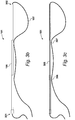
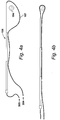
Figures 4a and 4b show the boat mooring line apparatus in side views being used to attach a rope about a mooring piling; and -
Figures 5a, 5b and 5c show second, third and fourth versions of a boat mooring line apparatus according to alternative embodiments of the present invention. - An example of an environment in which a boat mooring line apparatus according to a specific embodiment of the present invention can be used is illustrated in a perspective view in
Figure 1 . - Referring to the Figure, a boat
mooring line apparatus 101 according to one embodiment of the present invention is being used by aboatman 102 aboardboat 103 to attach theboat 103 to a mooring fixture, in the specific example to themooring piling 104, fixed todock 105. As will be described in further detail in relation to later Figures, boatmooring line apparatus 101 comprises principally of a substantially rigidelongated pole 106 and a length ofmooring line rope 107 guided by thepole 106 so as to extend substantially the length of the pole. - It will of course be appreciated that, whilst in the specific example of the invention described in detail herein, boat
mooring line apparatus 101 is shown being used to attach a rope about mooringpiling 104, in practice boatmooring line apparatus 101 could be used to attach a rope about any mooring point fixture. In particular, it will be appreciated that, in certain territories, for example, the United Kingdom, a more common form of mooring point fixture is a 'cleat', usually constructed of metal. It will be appreciated that boatmooring line apparatus 101 may be used to attach a mooring line rope to a variety of different forms of mooring point fixtures, including both traditional pilings and the more modern cleat. - Thus, as shown in the Figure, the
boatman 102 may guide theboat 103 under its own power towards thedock 105 to bring theboat 103 near and generally parallel to thedock 105. The boatman may then lean outwardly of the boat withmooring line apparatus 101, grasping one end ofpole 106, and usingpole 106 to guide the loop ofmooring rope 107 overmooring piling 104. As illustrated in the Figure, the free ends ofmooring line rope 107 may be secured to theboat 103, for example, to themid ship cleat 108 of theboat 103, so as to attach theboat 103 to thedock 105 by the loop ofmooring line 107. - It will of course be appreciated however that, although a rope guide apparatus according to the present invention may find particular utility when configured as a boat mooring line apparatus for mooring a boat, it is not limited in its utility to such an application. Rather, a rope guide apparatus, possibly similar in construction to mooring
line apparatus 101, may be used for attaching a loop of rope to an object in other situations, for example, for a person standing on a dockside to attach a loop of rope about an object floating in water adjacent the dock, to thereby allow retrieval of the object. In a particular alternative example, a rope guide apparatus according to one alternative embodiment of the present invention might be configured for use for rescue purposes, for example, to be used by rescue personnel aboard a rescue vessel to retrieve a person floating in the water. As a still further alternative example, a rope guide apparatus might be used by ground personnel for steadying of a structural beam being lowered into position by a crane. - A method of using the mooring line apparatus previously identified in
Figure 1 tomoor boat 103 is illustrated schematically inFigures 2a, 2b and 2c . - Referring to the Figures, the situation of
boat 103 inFigure 2a is broadly similar to the positioning of theboat 103 inFigure 1 . Thus, referring toFigure 2a , as previously described, the helmsman may position the boat under its own power close, and generally parallel to, thedock 105. Having attached the free ends of themooring line rope 107 of themooring line apparatus 101 to, for example, themid-ship cleat 108 of the boat, the boatman may then lean outwardly of the boat graspingelongated pole 106 as to loop the end of the mooring line rope about themooring piling 104. - Once the mooring line rope is looped about the
mooring piling 104, as inFigure 2b , the boatman may then let go ofpole 106 and, typically by applying forward thrust using the boats engine or other propulsion means, manoeuvre the boat under power to tension the loop ofmooring line 107, and so control the position of the boat relative to the dock. - Thus, as shown in
Figure 2c , by using the boats engine to drive the boat forward to tension themooring line rope 107, the boat will tend to be drawn gently towards thedock side 105. In this respect, in the illustrated examplemooring line apparatus 101 is being used in the manner of a 'spring'. The boatman may then attach further mooring line ropes as desired without the requirement to lean excessively outwardly of the boat or to jump a large gap between the boat and the dockside. Moreover, in the case of a one-man crewed boat, the lone boatman may, having attached themooring line apparatus 101 and having manoeuvred the boat towards the position shown inFigure 2C , set the boats engine to continue providing gentle forward thrust, thereby pinning the boat against the dockside, whilst disembarking the boat safely to attach further mooring lines as required. -
Mooring line apparatus 101 is shown in a close up perspective view inFigure 3a , a side elevation view inFigure 3b , a side cross-sectional view inFigure 3c , a partially exploded view inFigure 3d , and in a close-up end view inFigure 3e . - As previously described, in the specific embodiment the rope guide apparatus is configured as a boat
mooring line apparatus 101 suitable for mooring of boats, and comprises principally of an axiallyelongated pole 106 having first and second ends 301, 302 respectively, and a length ofmooring line rope 107 having first and second free ends 303, 304 respectively. In the embodiment, saidrope 107 is comprised of braided strands of a polyester plastics materials, but it will of course be appreciated could be comprised of alternative materials, such as textile strands or metallic wires. In essence,rope 107 should be flexible and sufficiently strong as to not be broken when relatively high tensile forces are exerted thereon. - As will be described, in the specific embodiment,
pole 106 is an axially elongated hollow tube, the first and second ends 301, 302 of which are open, and which are communicated by anaxial bore 305 extending the full length of the tube between the first and second open ends. In the embodiment,elongated tube 106 is constructed of a carbon-fibre reinforced plastics material, which construction is selected for its advantageous combination of strength, high rigidity, and low weight. In the embodiment,elongated tube 106 is constructed so as to be substantially rigid along its length, such that the tube may conveniently guide and support the mass ofrope 107 without undergoing excessive distortion. It will of course be appreciated thattube 106 could alternatively be constructed of other materials, for example, a homogenous plastics materials, wood, or metal. - Thus, referring to the drawings, in the embodiment the boat
mooring line apparatus 101 comprises axially elongatedtube 106 having first and second open ends 301, 302,tube 106 defining internally anaxial bore 305 extending therebetween, and a length of flexiblemooring line rope 107. Said flexiblemooring line rope 107 is arranged such that approximately a first half of its length extends from thefirst end 301 to thesecond end 302 of thetube 106, and a second half of its length extends in the opposite direction, such that both ends 303, 304 of therope 107 extend freely from thetube 106.Rope 107 is thus supported bytube 106 so as to generally form a closed loop, in which both free ends of the rope are returned generally towards the first end of thetube 106. - Referring in particular to
Figure 3c , it can be seen that said length ofrope 107 is arranged to enter theaxial bore 305 oftube 106 through said firstopen end 301, and that saidfirst end 303 of saidrope 107 is arranged to extend freely therefrom so as to be suitable for attaching to an anchor point, for example, themid-ship cleat 108 ofboat 103.Rope 107 is slidably retained within saidelongated tube 106 adjacent thefirst end 301 by the walls of thetube 106, which act to retain therope 107 within thetube 106 from the point at which therope 107 enters thetube 106 at the firstopen end 301, to the point at which therope 107 exits thetube 106 at thesecond end 302. Thus, in the embodiment, saidrope 107 is slidably retained within saidtube 106 along the full length of the portion ofrope 107 that extends within theaxial bore 305 oftube 106. - As shown in the drawings, said
rope 107 is arranged so as to extend outwardly of the secondopen end 302 of thetube 106, and then return backwardly generally towards the firstopen end 301 externally to thetube 106. Thus, as illustrated, saidrope 107 is arranged to extend outwardly of thesecond end 302 of thetube 106 and continuously therefrom generally towards saidfirst end 301 of saidpole 106 towards retainingfixture 307. - In the specific embodiment, retaining
fixture 307 takes the form of an eyelet protruding radially outwardly of the outer surface of thetube 106, and through which therope 106 passes to thereby slidably retain therope 107 close to thetube 106 at the point of theeyelet 307.Eyelet 307 is located between said first and second ends 301, 302 of saidtube 106, in the specific embodiment,eyelet 307 is located between saidsecond end 302 of saidtube 106 and the midpoint of saidtube 106. As illustrated, saidrope 107 is not retained relative to thetube 107 between the secondopen end 302 of thetube 106 and the retainingeyelet 307, and thus therope 106 is allowed to hang freely between the secondopen end 302 of thetube 106 and theeyelet 307 thereby defining a loose loop. - In the specific embodiment,
tube 106 comprises afurther eyelet 306 positioned intermediate the midpoint of thetube 106 and said firstopen end 301. Thus, as illustrated, in theembodiment rope 107 is arranged to pass througheyelet 306 after passing througheyelet 307 so as to slidably retainrope 107 close to thetube 106, andrope 107 is arranged to extend freely fromeyelet 306.Eyelet 306 ensures that the secondfree end 304 ofrope 107 is returned generally towards thefirst end 301 of thetube 106 rather than hanging freely from theeyelet 307. - Thus, as described, said
rope 107 is arranged as a loop, slidably retained with respect to thetube 106, such that the rope is guided to extend throughtube 106, entering through said firstopen end 301, exiting the tube through the secondopen end 302, and being guided back towards thefirst end 301 by way ofeyelets rope 107 will tend to fall naturally proximal thefirst end 301 of thetube 106. -
Rope 107 is advantageously slidably retained with respect to saidtube 106, firstly by the internal wall of saidtube 106, and subsequently by saideyelets rope 107 is retained close to or within thetube 106 at the points of retention, but such thatrope 107 may readily slide with respect totube 106 in a direction generally parallel to the axis of saidtube 106. Specifically, in the example, saidrope 107, saidaxial bore 305, and saideyelets rope 107 is substantially less than the width of saidaxial bore 305 and of the apertures ofeyelets rope 107 may readily slide relative to each of the points of retention, with each point of retention only exerting minimal frictional resistance on the rope. In the specific example,axial bore 305 has a cross-sectional width of approximately 40 millimetre, the apertures ofeyelets 306, 307 a width of approximately, 20 millimetre, and rope 107 a width of approximately 15 millimetre, although it will of course be appreciated that these dimensions may be varied in the case of alternative embodiments of the invention. - As described,
rope 107 is arranged so as to form a continuous loop between said first and second free ends 303, 304, with both free ends 303, 304 being supported generally proximal thefirst end 301 of thetube 106. Moreover, as described,rope 107 is slidably retained about the loop totube 106, and may slide freely relative totube 106, through saidtube 106 and the apertures of saideyelets tube 106. That both free ends 303, 304 of saidrope 107 extend freely and are not secured to thetube 107, and that the rope is allowed to slide freely relative to thetube 106, advantageously means that therope 107 does not exert any tension on thetube 106 when the rope is attached to an object, for example, to a mooring point, rather, all tension is borne solely by therope 107. - It will be appreciated then that a benefit of the claimed arrangement is that the
tube 106 serves solely as a guide for therope 107, which in the specific embodiment may be used to guide the loop ofrope 107 formed between the secondopen end 302 of thetube 106 and thefirst eyelet 307 about a mooring point. As neither end of therope 107 is secured to thetube 106, and as therope 107 may slide freely through thetube 106 and theeyelets rope 107, as would occur when the apparatus is being used to moor a boat in the manner previously described with reference toFigures 2a to 2c , does not exert any tension or other significant force ontube 106. - As a result,
tube 106 may have a relatively lighter weight construction, as it is required to resist deformation or breakage only to relatively low applied loads. It will be appreciate that, were one or more ends ofrope 107 secured totube 106, for example, secured totube 106 proximal thesecond end 302 so as to form the loop, or if the rope were statically, rather than slidably, retained to the tube, thentube 106 would be required to resist the full tensile load exerted on the rope between the boat and the dock, and so would be required to have a stronger, and thus likely heavier, construction. - Further, that
rope 107 is guided bytube 106 so as to form a loop, with both free ends 303, 304 of therope 107 hanging freely from thetube 106, allows a relatively weaker/thinner rope to be used, as the tension exerted on the rope during mooring is divided equally between the two halves of the rope. It will be appreciated that a disadvantage of using a single length of rope, potentially arranged to extend through thetube 107 and forming a closed loop at the end of the single length, is that a relatively stronger, and so likely thicker, rope would be required. Moreover, as will be described with particular reference toFigures 5b and 5c , the arrangement ofrope 107 as a continuous loop more easily allows for a loop of the rope formed adjacent to the second end of thetube 106 to be looped about a mooring fixture, such as mooring piling 104. It will be appreciated that, a disadvantage of an apparatus in which a single length of rope is arranged to form a closed loop at the end of the single length adjacent the second end of the tube, is that difficulties may be encountered when using the apparatus in keeping the 'loop' open, and so allowing it to be placed about a mooring fixture. - Indeed, referring in particular to
Figure 3d , in the specific embodiment, saidtube 106 is comprised of a plurality of discrete pole sections, in the example, three discrete pole sections, 308, 309, 310. The plurality ofdiscrete pole sections 308 to 310 are configured to be readily separable and attachable from one another, the pole sections being configured to be readily attachable by way of partially inserting an end of a first pole section into an open end of a second pole section, the ends of the respective pole sections being dimensioned so as to be retained by way of an interference fit. It will be appreciated that such a modular construction oftube 106 would likely be unsuitable if the tube were required to transmit significant tensile forces. - A particular advantage of this modular construction of said
elongated tube 106 is that the overall length of the tube may be readily increased or decreased simply by adding or removing additional pole sections from the end of the tube. Thus, as an example, in the event that the mooring line apparatus is to be used to moor a relatively large boat, it may be desirable for theelongated tube 106 to be relatively longer in length than a mooring apparatus used for mooring of a relatively small pleasure craft. - As an alternative to the readily separable and attachable discrete pole sections illustrated in
Figure 3d , thetube 106 could alternatively be constructed so as to allow the sections of the pole to slide telescopically between respective retracted and extended positions, so as to allow the overall length of thetube 106 to be readily increased or decreased by telescoping the pole sections. - A method of using the boat
mooring line apparatus 101 is shown inFigures 4a and 4b . - Referring to the Figures, the condition of the boat mooring line apparatus in
Figure 4a generally corresponds to its condition as shown previously inFigures 1 andFigure 2a . Thus, as previously described, when the boatman is bringing the boat alongside the dock, he may prepare the mooring line apparatus such that themooring line rope 304 forms a loose loop between the secondopen end 302 of thetube 106 and theeyelet 307. The boatman may then manoeuvre this loop of line over the mooring piling 104, with the free ends 303, 304 of therope 107 attached to a cleat on the boat. - Referring then to
Figure 4B , as previously described in relation toFigures 2b and Figure 2c , the boatman may then let go of theelongated tube 301, and manoeuvre the boat so as to bring themooring line rope 107 under tension. Thus, as illustrated inFigure 4B , because of the arrangement ofmooring line rope 107 with respect toelongated tube 106, and in particular because both free ends 303, 304 of saidrope 107 are attached to the boat, even when themooring line rope 107 is in the tensioned condition as shown inFigure 4b , the tensioned rope does not exert any significant force ontube 106. Rather, as previously described, in this arrangement,tube 106 serves merely as a guide for the rope when in the untensioned condition, and, given that therope 107 may slide freely relative totube 106 through theaxial bore 305 and theeyelets tube 106 itself is not tensioned by therope 107 even when therope 107 is under tension. - Alternative embodiments of a boat mooring line apparatus according to the present invention are shown in
Figures 5a, 5b and 5c . - Referring firstly to
Figure 5a , a firstalternative embodiment 501 of a boat mooring line apparatus is shown in a slide elevation view. Referring to the Figure, as illustrated, boatmooring line apparatus 501 has a substantially similar construction to boatmooring line apparatus 101 previously illustrated with respect toFigures 1 to 4 , in as much that it comprises principally of a substantially rigidelongated pole 502 having first and second ends 503, 504, and a length ofmooring line rope 505 having first and second ends 506, 507 respectively. In this embodiment, saidrope 503 is arranged to extend in both directions externally to thepole 502, rather than extending partly through the pole. - In this embodiment,
pole 502 is provided with a plurality of retainingfixtures 508 to 511, each in the form of an eyelet extending radially outwardly of the outer surface ofpole 502, which eyelets slidably retain therope 505 close to thepole 502 at each position. Thus,eyelet 508 is located adjacent saidfirst end 503 of saidpole 502, from which point saidfirst end 506 of saidrope 505 extends freely, andeyelet 511 is located adjacent saidsecond end 504 of saidpole 502, andrope 505 is arranged to extend between saideyelets pole 502 byintermediate eyelets eyelet 511rope 505 is arranged to extend continuously towards thefirst end 503 of the pole, and is slidably retained byintermediate eyelets second end 507 of rope is allowed to extend freely from thepole 502. - Referring secondly to
Figure 5b , a secondalternative embodiment 512 of a boat mooring line apparatus is shown in a side-cross sectional view. Referring to the Figure, it will be noted thatapparatus 512 is substantially similar in construction toapparatus 101 described previously with reference toFigures 1 to 4 , inasmuch that it comprises an axially elongatedrigid tube 513 having first and second open ends and defining internally an axial bore extending therebetween. - It will be noted that the principal difference between
apparatus 512 andapparatus 101 is that the rope ofapparatus 512 is routed through the axial bore oftube 513 both in a first direction from thefirst end 514 of the tube towards thesecond end 515, and in the reverse direction. Accordingly, given that both halves of the rope are slidably retained internally by thetube 513,tube 513 is not provided with externally protruding retaining fixture, such as the retaining eyelets ofapparatus 101. - Referring finally to
Figure 5c , a thirdalternative embodiment 516 of a boat mooring line apparatus is shown in a side cross sectional view. It will be noted that theapparatus 516 is substantially similar in construction toapparatus 512, and like components will be referenced using like numerals.Apparatus 516 is however further provided adjacent thesecond end 515 of saidpole 513 with astrut 517, which strut comprises aneyelet 518 through which the rope slidably passes. As will be appreciated, the primary purpose ofstrut 517 is to hold open the loop of rope formed adjacent thesecond end 515 of thepole 513 to more easily allow for the loop to be passed over a mooring point, such as mooring piling 104 described with reference toFigure 1 . - It will of course be appreciated that, like
apparatus 101, apparatus according to the present invention taking the form of any ofapparatus
Claims (15)
- A rope guide apparatus (101); the apparatus (101) comprising:an elongate pole (106) having first (301) and second ends (302); anda length of rope (107) having first (303) and second (304) ends;characterised in thatsaid length of rope (107) is slidably retained by the elongate pole (106) at a first point of retention located adjacent the first end (301) of the elongated pole (106) from which point the first end (303) of said rope (107) extends freely from the elongate pole (106), and in which the rope (107) is arranged to extend from the first end (301) thereof towards the second end (302) of the elongate pole (106) and is slidably retained by the elongate pole (106) at a second point of retention adjacent the second end (302) thereof, and in which the rope (107) is arranged to extend continuously from adjacent the second end (302) of the elongate pole (106) towards the first end (301) of the elongate pole (106) and is slidably retained by the elongate pole (106) at a third point of retention located either adjacent the first end (301) of the elongate pole (106) or intermediate the first (301) and second ends (302) of the elongate pole (106), and in which the second end (304) of the length of rope (107) extends freely from the elongate pole (106).
- The rope guide apparatus of claim 1, in which said elongate pole 106) is substantially rigid along its length.
- The rope guide apparatus of claim 1 or claim 2, in which the third point of retention is located between the second end (302) of the elongate pole (106) and a mid-point of the elongate pole (106) between the first (301) and second ends (302).
- The rope guide apparatus of any of claims 1 to 3, in which the length of rope (107) is slidably retained by the elongate pole (106) at each point of retention such as to allow the rope (107) to slide relative to the respective point of retention generally parallel to a longitudinal axis of the pole (106) while retaining the rope (107) close to or within the elongate pole (106) at each point of retention.
- The rope guide apparatus of any of claims 1 to 4, in which at least the third point of retention is defined by a retaining fixture (307).
- The rope guide apparatus of claim 5, in which the retaining fixture (307) is formed by a protrusion extending from the elongate pole (106), said protrusion is shaped to slidably retain the length of rope (107) at the respective point of retention.
- The rope guide apparatus of either claim 5 or claim 6, in which at least the third point of retention comprises an eyelet (508, 509, 510 and 511) and the rope is arranged to pass through said eyelet.
- The rope guide apparatus of any of claims 5 to 7, in which said elongate pole (106) comprises an elongate tube having first (301) and second (302) open ends and defining internally an axial bore (305) extending therebetween.
- The rope guide apparatus of any of claims 5 to 8, in which the length of rope (107) is arranged to extend at least partly within said elongate tube 106 along said axial bore (305) and is arranged such that the first end (303) of the rope (107) extends freely outwardly of the first open end (301) of the elongate tube (106), and such that the second end (304) of the rope (107) extends outwardly of the second open end (302) of the elongate tube (106) and continuously therefrom towards the first end (301) of the elongate tube (106).
- The rope guide apparatus of claim any of claims 5 to 9, in which the length of rope (107) is arranged such that the rope (107) extends outwardly of the elongate tube (106) and continuously therefrom towards said first end (301) of said elongate tube (106) external to said elongate tube (106).
- The rope guide apparatus of any of claims 5 to 10, in which the elongate tube (106) comprises an eyelet at the third point of retention protruding radially outwardly of the outer surface of the elongate tube (106).
- The rope guide apparatus of any of claims 1 to 11, in which the elongate pole (106) comprises a plurality of discrete pole sections (308, 309 and (310).
- The rope guide apparatus of claim 12, in which the plurality of discrete pole sections (308, 309 and (310) are configured to be readily separable and attachable.
- The rope guide apparatus of claim 12 or claim 13, in which the plurality of discrete pole sections (308, 309 and (310) are configured to be readily attachable by way of partial insertion of an end of a first pole section (308) into an open end of a second pole section (309).
- A boat mooring line apparatus (501); the apparatus comprising:a substantially rigid elongate tube (513) having first (514) and second (515) open ends and an axial bore (305); anda length of rope (505) having first (506) and second (507) ends;characterised in thatthe length of rope (505) is arranged to partly extend within the tube (513) along its axial bore (305), and is arranged such that the first end (506) of the rope (505) extends freely outwardly of the first open end (514) of the elongate tube (513), and such that the second end (507) of the rope (505) extends outwardly of the second open end (515) of the elongate tube (513) then back towards the first end (514) of the elongate tube (513) externally to the elongate tube (513), and in which the length of rope (505) is slidably retained by at least one retaining fixture (508, 509, 510 and 511) protruding outwardly from an outer surface of the elongate tube (513) located intermediate the second open end (515) and a midpoint of the elongate tube (513), and in which the second end (507) of the length of rope (505) extends freely from the elongate tube (513).
Applications Claiming Priority (1)
| Application Number | Priority Date | Filing Date | Title |
|---|---|---|---|
| GB1711515.5A GB2564663A (en) | 2017-07-18 | 2017-07-18 | Rope guide apparatus |
Publications (2)
| Publication Number | Publication Date |
|---|---|
| EP3431381A1 true EP3431381A1 (en) | 2019-01-23 |
| EP3431381B1 EP3431381B1 (en) | 2022-08-31 |
Family
ID=59713566
Family Applications (1)
| Application Number | Title | Priority Date | Filing Date |
|---|---|---|---|
| EP18000602.5A Active EP3431381B1 (en) | 2017-07-18 | 2018-07-17 | Rope guide apparatus |
Country Status (4)
| Country | Link |
|---|---|
| US (1) | US10946936B2 (en) |
| EP (1) | EP3431381B1 (en) |
| ES (1) | ES2928554T3 (en) |
| GB (1) | GB2564663A (en) |
Families Citing this family (3)
| Publication number | Priority date | Publication date | Assignee | Title |
|---|---|---|---|---|
| DE102020116493A1 (en) | 2020-06-23 | 2021-12-23 | Atlas Elektronik Gmbh | Device and method for recovering an unmanned watercraft from the water |
| US11505285B2 (en) * | 2021-01-22 | 2022-11-22 | Joseph Greco | Boat dock mooring system |
| US12024311B1 (en) * | 2022-08-15 | 2024-07-02 | United States Of America As Represented By The Secretary Of The Air Force | Remotely operable cover for aircraft refueling boom |
Citations (5)
| Publication number | Priority date | Publication date | Assignee | Title |
|---|---|---|---|---|
| US4667617A (en) * | 1984-08-20 | 1987-05-26 | Molitor Jerome A | Rope-holding boat hook |
| DE20200120U1 (en) * | 2002-01-05 | 2003-05-15 | Müller, Wolfgang, 21217 Seevetal | Boat hook mooring rod adapter for painter rope secured at one end to the boat and passing through an adapter fixture attached to the rod where the triangular fitting with one hole for the rod allows free movement of the painter |
| GB2426965A (en) * | 2005-05-20 | 2006-12-13 | Donald Alexander Fraser | Mooring aid device comprising a rigid hollow body |
| WO2012119202A1 (en) * | 2011-03-10 | 2012-09-13 | Galante Romeo | Boat securing device |
| US20120228891A1 (en) * | 2009-11-10 | 2012-09-13 | Sara Howard | Apparatus and Method for Docking a Boat |
Family Cites Families (4)
| Publication number | Priority date | Publication date | Assignee | Title |
|---|---|---|---|---|
| US3224404A (en) * | 1964-11-06 | 1965-12-21 | Jong George E De | Mooring device |
| US3878808A (en) | 1973-11-12 | 1975-04-22 | Jr Presley J Mock | Combination boat hook and mooring apparatus |
| US5586514A (en) * | 1995-03-29 | 1996-12-24 | Yuscavage; Thomas M. | Mooring device |
| US20040237867A1 (en) | 2003-06-02 | 2004-12-02 | Dunn John S. | Boat docking system and method |
-
2017
- 2017-07-18 GB GB1711515.5A patent/GB2564663A/en not_active Withdrawn
-
2018
- 2018-07-17 ES ES18000602T patent/ES2928554T3/en active Active
- 2018-07-17 EP EP18000602.5A patent/EP3431381B1/en active Active
- 2018-07-17 US US16/038,172 patent/US10946936B2/en active Active
Patent Citations (5)
| Publication number | Priority date | Publication date | Assignee | Title |
|---|---|---|---|---|
| US4667617A (en) * | 1984-08-20 | 1987-05-26 | Molitor Jerome A | Rope-holding boat hook |
| DE20200120U1 (en) * | 2002-01-05 | 2003-05-15 | Müller, Wolfgang, 21217 Seevetal | Boat hook mooring rod adapter for painter rope secured at one end to the boat and passing through an adapter fixture attached to the rod where the triangular fitting with one hole for the rod allows free movement of the painter |
| GB2426965A (en) * | 2005-05-20 | 2006-12-13 | Donald Alexander Fraser | Mooring aid device comprising a rigid hollow body |
| US20120228891A1 (en) * | 2009-11-10 | 2012-09-13 | Sara Howard | Apparatus and Method for Docking a Boat |
| WO2012119202A1 (en) * | 2011-03-10 | 2012-09-13 | Galante Romeo | Boat securing device |
Also Published As
| Publication number | Publication date |
|---|---|
| US20190023355A1 (en) | 2019-01-24 |
| GB2564663A (en) | 2019-01-23 |
| US10946936B2 (en) | 2021-03-16 |
| GB201711515D0 (en) | 2017-08-30 |
| ES2928554T3 (en) | 2022-11-21 |
| EP3431381B1 (en) | 2022-08-31 |
Similar Documents
| Publication | Publication Date | Title |
|---|---|---|
| US7032529B2 (en) | Shock absorbing line device | |
| US10946936B2 (en) | Rope guide apparatus | |
| US5330378A (en) | Float for ropes | |
| US20090223428A1 (en) | Anchoring system for watercraft vessels | |
| ES2918549T3 (en) | System and method of emergency boat towing | |
| US8443748B2 (en) | Docking aid apparatus with utility implement | |
| CN102438886A (en) | Method and device for manipulating a cable | |
| EP2001735A2 (en) | Anchoring system and method | |
| US8683735B1 (en) | Horizontally opposed universal outrigger assembly | |
| US2536682A (en) | Sea anchor apparatus | |
| US10953971B1 (en) | Adjustable halyard tensioner | |
| US9211938B1 (en) | Dual rod mooring pendant apparatus | |
| US8967066B1 (en) | Automatic docking line management system | |
| US5598805A (en) | Mooring line receptacle apparatus | |
| ITMI950810A1 (en) | SINGLE CABLE BLOCK FUNICULAR SYSTEM WITH MULTIPLE MECHANICAL ADVANTAGE | |
| US10676161B1 (en) | Boat tethering and launching device | |
| WO2019170206A1 (en) | Remote releasable line lock device and method and a sailboat comprising the spinnaker recovering system with a remote releasable line lock device | |
| US5327842A (en) | Sail control system | |
| JP6964339B2 (en) | How to hold the onboard boat using the boat davit and the onboard boat holding mechanism | |
| RU2707479C2 (en) | Dynamic loads compensation device in tow line | |
| US2985896A (en) | Apparatus for retrieving | |
| NO338343B1 (en) | Mooring, lifting and / or rope line and method for making the same | |
| US11661152B2 (en) | Assembly for anchoring a submerged vessel | |
| US20120298026A1 (en) | Sail Mounting Assembly | |
| US20240010303A1 (en) | An anchor for a watercraft |
Legal Events
| Date | Code | Title | Description |
|---|---|---|---|
| PUAI | Public reference made under article 153(3) epc to a published international application that has entered the european phase |
Free format text: ORIGINAL CODE: 0009012 |
|
| STAA | Information on the status of an ep patent application or granted ep patent |
Free format text: STATUS: THE APPLICATION HAS BEEN PUBLISHED |
|
| AK | Designated contracting states |
Kind code of ref document: A1 Designated state(s): AL AT BE BG CH CY CZ DE DK EE ES FI FR GB GR HR HU IE IS IT LI LT LU LV MC MK MT NL NO PL PT RO RS SE SI SK SM TR |
|
| AX | Request for extension of the european patent |
Extension state: BA ME |
|
| STAA | Information on the status of an ep patent application or granted ep patent |
Free format text: STATUS: REQUEST FOR EXAMINATION WAS MADE |
|
| 17P | Request for examination filed |
Effective date: 20190312 |
|
| RBV | Designated contracting states (corrected) |
Designated state(s): AL AT BE BG CH CY CZ DE DK EE ES FI FR GB GR HR HU IE IS IT LI LT LU LV MC MK MT NL NO PL PT RO RS SE SI SK SM TR |
|
| STAA | Information on the status of an ep patent application or granted ep patent |
Free format text: STATUS: EXAMINATION IS IN PROGRESS |
|
| 17Q | First examination report despatched |
Effective date: 20190611 |
|
| GRAP | Despatch of communication of intention to grant a patent |
Free format text: ORIGINAL CODE: EPIDOSNIGR1 |
|
| STAA | Information on the status of an ep patent application or granted ep patent |
Free format text: STATUS: GRANT OF PATENT IS INTENDED |
|
| INTG | Intention to grant announced |
Effective date: 20220414 |
|
| GRAS | Grant fee paid |
Free format text: ORIGINAL CODE: EPIDOSNIGR3 |
|
| GRAA | (expected) grant |
Free format text: ORIGINAL CODE: 0009210 |
|
| STAA | Information on the status of an ep patent application or granted ep patent |
Free format text: STATUS: THE PATENT HAS BEEN GRANTED |
|
| AK | Designated contracting states |
Kind code of ref document: B1 Designated state(s): AL AT BE BG CH CY CZ DE DK EE ES FI FR GB GR HR HU IE IS IT LI LT LU LV MC MK MT NL NO PL PT RO RS SE SI SK SM TR |
|
| REG | Reference to a national code |
Ref country code: CH Ref legal event code: EP Ref country code: GB Ref legal event code: FG4D |
|
| REG | Reference to a national code |
Ref country code: AT Ref legal event code: REF Ref document number: 1515117 Country of ref document: AT Kind code of ref document: T Effective date: 20220915 |
|
| REG | Reference to a national code |
Ref country code: DE Ref legal event code: R096 Ref document number: 602018039885 Country of ref document: DE |
|
| REG | Reference to a national code |
Ref country code: IE Ref legal event code: FG4D |
|
| REG | Reference to a national code |
Ref country code: CH Ref legal event code: PK Free format text: BERICHTIGUNGEN |
|
| REG | Reference to a national code |
Ref country code: DE Ref legal event code: R081 Ref document number: 602018039885 Country of ref document: DE Owner name: MILLER, STEVEN MAURICE, GB Free format text: FORMER OWNER: MILLER, STEVEN MAURICE, RAVENSTHORPE, NORTHAMPTON, GB |
|
| RAP4 | Party data changed (patent owner data changed or rights of a patent transferred) |
Owner name: MILLER, STEVEN MAURICE |
|
| RIN2 | Information on inventor provided after grant (corrected) |
Inventor name: MILLER, STEVEN MAURICE |
|
| REG | Reference to a national code |
Ref country code: NL Ref legal event code: FP |
|
| REG | Reference to a national code |
Ref country code: ES Ref legal event code: FG2A Ref document number: 2928554 Country of ref document: ES Kind code of ref document: T3 Effective date: 20221121 |
|
| REG | Reference to a national code |
Ref country code: LT Ref legal event code: MG9D |
|
| PG25 | Lapsed in a contracting state [announced via postgrant information from national office to epo] |
Ref country code: SE Free format text: LAPSE BECAUSE OF FAILURE TO SUBMIT A TRANSLATION OF THE DESCRIPTION OR TO PAY THE FEE WITHIN THE PRESCRIBED TIME-LIMIT Effective date: 20220831 Ref country code: RS Free format text: LAPSE BECAUSE OF FAILURE TO SUBMIT A TRANSLATION OF THE DESCRIPTION OR TO PAY THE FEE WITHIN THE PRESCRIBED TIME-LIMIT Effective date: 20220831 Ref country code: NO Free format text: LAPSE BECAUSE OF FAILURE TO SUBMIT A TRANSLATION OF THE DESCRIPTION OR TO PAY THE FEE WITHIN THE PRESCRIBED TIME-LIMIT Effective date: 20221130 Ref country code: LV Free format text: LAPSE BECAUSE OF FAILURE TO SUBMIT A TRANSLATION OF THE DESCRIPTION OR TO PAY THE FEE WITHIN THE PRESCRIBED TIME-LIMIT Effective date: 20220831 Ref country code: LT Free format text: LAPSE BECAUSE OF FAILURE TO SUBMIT A TRANSLATION OF THE DESCRIPTION OR TO PAY THE FEE WITHIN THE PRESCRIBED TIME-LIMIT Effective date: 20220831 Ref country code: FI Free format text: LAPSE BECAUSE OF FAILURE TO SUBMIT A TRANSLATION OF THE DESCRIPTION OR TO PAY THE FEE WITHIN THE PRESCRIBED TIME-LIMIT Effective date: 20220831 |
|
| REG | Reference to a national code |
Ref country code: AT Ref legal event code: MK05 Ref document number: 1515117 Country of ref document: AT Kind code of ref document: T Effective date: 20220831 |
|
| PG25 | Lapsed in a contracting state [announced via postgrant information from national office to epo] |
Ref country code: PL Free format text: LAPSE BECAUSE OF FAILURE TO SUBMIT A TRANSLATION OF THE DESCRIPTION OR TO PAY THE FEE WITHIN THE PRESCRIBED TIME-LIMIT Effective date: 20220831 Ref country code: IS Free format text: LAPSE BECAUSE OF FAILURE TO SUBMIT A TRANSLATION OF THE DESCRIPTION OR TO PAY THE FEE WITHIN THE PRESCRIBED TIME-LIMIT Effective date: 20221231 Ref country code: HR Free format text: LAPSE BECAUSE OF FAILURE TO SUBMIT A TRANSLATION OF THE DESCRIPTION OR TO PAY THE FEE WITHIN THE PRESCRIBED TIME-LIMIT Effective date: 20220831 Ref country code: GR Free format text: LAPSE BECAUSE OF FAILURE TO SUBMIT A TRANSLATION OF THE DESCRIPTION OR TO PAY THE FEE WITHIN THE PRESCRIBED TIME-LIMIT Effective date: 20221201 |
|
| PG25 | Lapsed in a contracting state [announced via postgrant information from national office to epo] |
Ref country code: SM Free format text: LAPSE BECAUSE OF FAILURE TO SUBMIT A TRANSLATION OF THE DESCRIPTION OR TO PAY THE FEE WITHIN THE PRESCRIBED TIME-LIMIT Effective date: 20220831 Ref country code: RO Free format text: LAPSE BECAUSE OF FAILURE TO SUBMIT A TRANSLATION OF THE DESCRIPTION OR TO PAY THE FEE WITHIN THE PRESCRIBED TIME-LIMIT Effective date: 20220831 Ref country code: PT Free format text: LAPSE BECAUSE OF FAILURE TO SUBMIT A TRANSLATION OF THE DESCRIPTION OR TO PAY THE FEE WITHIN THE PRESCRIBED TIME-LIMIT Effective date: 20230102 Ref country code: DK Free format text: LAPSE BECAUSE OF FAILURE TO SUBMIT A TRANSLATION OF THE DESCRIPTION OR TO PAY THE FEE WITHIN THE PRESCRIBED TIME-LIMIT Effective date: 20220831 Ref country code: CZ Free format text: LAPSE BECAUSE OF FAILURE TO SUBMIT A TRANSLATION OF THE DESCRIPTION OR TO PAY THE FEE WITHIN THE PRESCRIBED TIME-LIMIT Effective date: 20220831 Ref country code: AT Free format text: LAPSE BECAUSE OF FAILURE TO SUBMIT A TRANSLATION OF THE DESCRIPTION OR TO PAY THE FEE WITHIN THE PRESCRIBED TIME-LIMIT Effective date: 20220831 |
|
| PG25 | Lapsed in a contracting state [announced via postgrant information from national office to epo] |
Ref country code: SK Free format text: LAPSE BECAUSE OF FAILURE TO SUBMIT A TRANSLATION OF THE DESCRIPTION OR TO PAY THE FEE WITHIN THE PRESCRIBED TIME-LIMIT Effective date: 20220831 Ref country code: EE Free format text: LAPSE BECAUSE OF FAILURE TO SUBMIT A TRANSLATION OF THE DESCRIPTION OR TO PAY THE FEE WITHIN THE PRESCRIBED TIME-LIMIT Effective date: 20220831 |
|
| REG | Reference to a national code |
Ref country code: DE Ref legal event code: R097 Ref document number: 602018039885 Country of ref document: DE |
|
| PG25 | Lapsed in a contracting state [announced via postgrant information from national office to epo] |
Ref country code: AL Free format text: LAPSE BECAUSE OF FAILURE TO SUBMIT A TRANSLATION OF THE DESCRIPTION OR TO PAY THE FEE WITHIN THE PRESCRIBED TIME-LIMIT Effective date: 20220831 |
|
| PLBE | No opposition filed within time limit |
Free format text: ORIGINAL CODE: 0009261 |
|
| STAA | Information on the status of an ep patent application or granted ep patent |
Free format text: STATUS: NO OPPOSITION FILED WITHIN TIME LIMIT |
|
| 26N | No opposition filed |
Effective date: 20230601 |
|
| PG25 | Lapsed in a contracting state [announced via postgrant information from national office to epo] |
Ref country code: SI Free format text: LAPSE BECAUSE OF FAILURE TO SUBMIT A TRANSLATION OF THE DESCRIPTION OR TO PAY THE FEE WITHIN THE PRESCRIBED TIME-LIMIT Effective date: 20220831 |
|
| PGFP | Annual fee paid to national office [announced via postgrant information from national office to epo] |
Ref country code: CH Payment date: 20230801 Year of fee payment: 6 |
|
| PG25 | Lapsed in a contracting state [announced via postgrant information from national office to epo] |
Ref country code: LU Free format text: LAPSE BECAUSE OF NON-PAYMENT OF DUE FEES Effective date: 20230717 |
|
| PG25 | Lapsed in a contracting state [announced via postgrant information from national office to epo] |
Ref country code: LU Free format text: LAPSE BECAUSE OF NON-PAYMENT OF DUE FEES Effective date: 20230717 |
|
| PG25 | Lapsed in a contracting state [announced via postgrant information from national office to epo] |
Ref country code: IT Free format text: LAPSE BECAUSE OF FAILURE TO SUBMIT A TRANSLATION OF THE DESCRIPTION OR TO PAY THE FEE WITHIN THE PRESCRIBED TIME-LIMIT Effective date: 20220831 |
|
| PG25 | Lapsed in a contracting state [announced via postgrant information from national office to epo] |
Ref country code: BG Free format text: LAPSE BECAUSE OF FAILURE TO SUBMIT A TRANSLATION OF THE DESCRIPTION OR TO PAY THE FEE WITHIN THE PRESCRIBED TIME-LIMIT Effective date: 20220831 |
|
| PG25 | Lapsed in a contracting state [announced via postgrant information from national office to epo] |
Ref country code: BG Free format text: LAPSE BECAUSE OF FAILURE TO SUBMIT A TRANSLATION OF THE DESCRIPTION OR TO PAY THE FEE WITHIN THE PRESCRIBED TIME-LIMIT Effective date: 20220831 |
|
| REG | Reference to a national code |
Ref country code: CH Ref legal event code: PL |
|
| PG25 | Lapsed in a contracting state [announced via postgrant information from national office to epo] |
Ref country code: CH Free format text: LAPSE BECAUSE OF NON-PAYMENT OF DUE FEES Effective date: 20240731 |
|
| PG25 | Lapsed in a contracting state [announced via postgrant information from national office to epo] |
Ref country code: CY Free format text: LAPSE BECAUSE OF FAILURE TO SUBMIT A TRANSLATION OF THE DESCRIPTION OR TO PAY THE FEE WITHIN THE PRESCRIBED TIME-LIMIT; INVALID AB INITIO Effective date: 20180717 |
|
| PG25 | Lapsed in a contracting state [announced via postgrant information from national office to epo] |
Ref country code: HU Free format text: LAPSE BECAUSE OF FAILURE TO SUBMIT A TRANSLATION OF THE DESCRIPTION OR TO PAY THE FEE WITHIN THE PRESCRIBED TIME-LIMIT; INVALID AB INITIO Effective date: 20180717 |
|
| PGFP | Annual fee paid to national office [announced via postgrant information from national office to epo] |
Ref country code: NL Payment date: 20250716 Year of fee payment: 8 |
|
| PGFP | Annual fee paid to national office [announced via postgrant information from national office to epo] |
Ref country code: ES Payment date: 20250804 Year of fee payment: 8 |
|
| PGFP | Annual fee paid to national office [announced via postgrant information from national office to epo] |
Ref country code: DE Payment date: 20250716 Year of fee payment: 8 |
|
| PGFP | Annual fee paid to national office [announced via postgrant information from national office to epo] |
Ref country code: MC Payment date: 20250717 Year of fee payment: 8 |
|
| PGFP | Annual fee paid to national office [announced via postgrant information from national office to epo] |
Ref country code: GB Payment date: 20250715 Year of fee payment: 8 Ref country code: BE Payment date: 20250716 Year of fee payment: 8 |
|
| PGFP | Annual fee paid to national office [announced via postgrant information from national office to epo] |
Ref country code: FR Payment date: 20250715 Year of fee payment: 8 |
|
| PGFP | Annual fee paid to national office [announced via postgrant information from national office to epo] |
Ref country code: IE Payment date: 20250715 Year of fee payment: 8 |
|
| PG25 | Lapsed in a contracting state [announced via postgrant information from national office to epo] |
Ref country code: TR Free format text: LAPSE BECAUSE OF FAILURE TO SUBMIT A TRANSLATION OF THE DESCRIPTION OR TO PAY THE FEE WITHIN THE PRESCRIBED TIME-LIMIT Effective date: 20220831 |