EP3431307A1 - Wheel units for rail vehicles - Google Patents
Wheel units for rail vehicles Download PDFInfo
- Publication number
- EP3431307A1 EP3431307A1 EP17182629.0A EP17182629A EP3431307A1 EP 3431307 A1 EP3431307 A1 EP 3431307A1 EP 17182629 A EP17182629 A EP 17182629A EP 3431307 A1 EP3431307 A1 EP 3431307A1
- Authority
- EP
- European Patent Office
- Prior art keywords
- section
- wheel
- track
- tread
- cylindrical contour
- Prior art date
- Legal status (The legal status is an assumption and is not a legal conclusion. Google has not performed a legal analysis and makes no representation as to the accuracy of the status listed.)
- Granted
Links
Images



Classifications
-
- B—PERFORMING OPERATIONS; TRANSPORTING
- B60—VEHICLES IN GENERAL
- B60B—VEHICLE WHEELS; CASTORS; AXLES FOR WHEELS OR CASTORS; INCREASING WHEEL ADHESION
- B60B17/00—Wheels characterised by rail-engaging elements
- B60B17/0065—Flange details
- B60B17/0068—Flange details the flange being provided on a single side
-
- B—PERFORMING OPERATIONS; TRANSPORTING
- B60—VEHICLES IN GENERAL
- B60B—VEHICLE WHEELS; CASTORS; AXLES FOR WHEELS OR CASTORS; INCREASING WHEEL ADHESION
- B60B17/00—Wheels characterised by rail-engaging elements
- B60B17/0055—Wheels characterised by rail-engaging elements with non-elastic tyres (e.g. of particular profile or composition)
-
- B—PERFORMING OPERATIONS; TRANSPORTING
- B60—VEHICLES IN GENERAL
- B60B—VEHICLE WHEELS; CASTORS; AXLES FOR WHEELS OR CASTORS; INCREASING WHEEL ADHESION
- B60B2900/00—Purpose of invention
- B60B2900/10—Reduction of
- B60B2900/113—Production or maintenance time
Definitions
- the present invention relates to a wheel unit for a rail vehicle having a nominal speed above 140 km/h, in particular, a high-speed rail vehicle, the wheel unit comprising a rim section, wherein the rim section defines a rolling axis of the wheel, a rim width along the rolling axis and a tread datum plane perpendicular to the rolling axis.
- the rim section has a sectional contour in a sectional plane comprising the rolling axis, wherein the sectional contour comprises a wheel profile section.
- the wheel profile section comprises a flange section and a tread section, wherein the tread section is configured to contact a rail of a track in a contact location during normal operation of the wheel unit.
- the tread section in an unworn or re-profiled state, comprises a non-cylindrical contour section.
- the present invention further relates to a corresponding wheel set comprising two such wheel units, to a corresponding running gear for a rail vehicle comprising such a wheel set as well as a corresponding rail comprising such a running gear.
- the present invention further relates to a method for designing a wheel unit.
- Wheel units as described above are well known in the art and all share the common feature of a continuously curved wheel profile to achieve favorable wheel-to-rail contact conditions.
- An example of such a wheel profiles is the widely used profile referred to as "S1002" profile or the commonly used “EPS” profile as described in DIN EN 13715.
- EP 0 760 294 A2 describes wheel units referred to as "DBS-320", “DBS-315", “DBS-310” and “DBS-305", which are modified variants of the "S1002" profile in terms of curvature.
- DE 10 2006 034 896 B4 describes a wheel unit, referred to as "DBS 0525", which exhibits a tread section which is less inclined with respect to the rolling axis of the wheel than the tread section of the "S1002" profile.
- the present invention is based on the technical teaching that an improved wear behavior of the tread section and a slower wear-induced increase in the equivalent conicity can be accomplished, respectively, if the tread section comprises a cylindrical contour section.
- a cylindrical contour section of the tread section has the beneficial effect that, at least during operation at a nominal speed on a straight level track, an indifferent contact location behavior with a statistical distribution (over time) of the contact location along the rolling axis prevails over the cylindrical contour section.
- the cylindrical contour section is a continuous contour section.
- two or more cylindrical areas of the cylindrical contour section may be separated by (one or more) slightly non-cylindrical spaces, as long as the above indifferent contact loaction behavior and/or the above indifferent wear behavior is achieved over the cylindrical contour section.
- the present invention relates to a wheel unit for a rail vehicle having a nominal speed above 140 km/h, in particular, a high-speed rail vehicle, wherein the wheel unit comprises a rim section and the rim section defines a rolling axis of the wheel, a rim width along the rolling axis and a tread datum plane perpendicular to the rolling axis.
- the rim section has a sectional contour in a sectional plane comprising the rolling axis, wherein the sectional contour comprises a wheel profile section.
- the wheel profile section comprises a flange section and a tread section, wherein the tread section is configured to contact a rail of a track in a contact location during normal operation of the wheel unit.
- the tread section in an unworn or re-profiled state, comprises a non-cylindrical contour section.
- the tread section in an unworn or re-profiled state, further comprises a cylindrical contour section.
- the cylindrical contour section along the rolling axis, has an inner end, an outer end and a cylindrical contour width between the inner end and the outer end.
- the cylindrical contour section is located such that, along the rolling axis, one of the inner end and the outer end has an end distance from the tread datum plane which is at most 50% of the cylindrical contour width.
- the cylindrical contour section may intersect the tread datum plane.
- any desired and suitable location may be chosen for the inner end and the outer end of the cylindrical contour section and, hence, any suitable cylindrical contour width may be chosen.
- the end distance is 0% to 50%, preferably 10% to 40%, more preferably 20% to 30%, of the cylindrical contour width.
- the end distance is 0 mm to 30 mm, preferably 5 mm to 25 mm, more preferably 5 mm to 10 mm.
- the inner end of the cylindrical contour section has the end distance from the tread datum plane.
- the inner end is located between the flange section and the tread datum plane. In any of these cases particularly favorable indifferent contact location behavior and a favorable indifferent wear behavior, respectively, may be achieved over the cylindrical contour section.
- the cylindrical contour width is at least 4%, preferably at least 7%, more preferably at least 10%, of the rim width.
- the cylindrical contour width is at least 5 mm, preferably at least 10 mm, more preferably at least 15 mm.
- the cylindrical contour width is at most 14%, preferably at most 16%, more preferably at most 18%, of the rim width.
- the cylindrical contour width is at most 20 mm, preferably at most 22 mm, more preferably at most 25 mm. In any of these cases particularly favorable indifferent contact location behavior and a favorable indifferent wear behavior, respectively, may be achieved over a sufficiently large cylindrical contour section.
- the geometry of the cylindrical contour section is kept within certain favorable tolerances. These tolerances may depend on either of the material or material combination of the wheel and the rail, the track profile of the track (on which the wheel is to be used,), the operational parameters of the vehicle (in particular, nominal load, nominal speed etc.), manufacturing tolerances or any other parameter of noticeable influence as well as any combinations of these.
- the cylindrical contour section over the cylindrical contour width, has a deviation from an ideally cylindrical contour, wherein the deviation is such that a local inclination of the cylindrical contour section with respect to the ideally cylindrical contour is less than 1/200, preferably less than 1/250, more preferably less than 1/300.
- the wheel profile section comprises an at least partially curved fillet section (sometimes also referred to as the flange root section) which is located between the flange section and the inner end of the cylindrical contour section.
- the fillet section is preferably configured such that, at least in an unworn or re-profiled state, upon a lateral displacement of the rim section on the rail along the rolling axis during normal operation, the contact location continuously shifts over the fillet section.
- the fillet section is configured such that, at least in an unworn or re-profiled state, upon a lateral displacement of the rim section on the rail along the rolling axis at any time during normal operation on a straight track, the contact location forms the single coherent contact location between the rim section and the rail.
- the fillet section is preferably configured as a function of a geometry of the track on which the wheel unit is intended to be operated, in particular as a function of a curve radius distribution along the track.
- the fillet section may be configured as a function of a geometry of a rail head of the rail.
- the fillet section may be configured as a function of an inclination of the rail, in particular, as a function of a web of the rail, with respect to a wheel-rail contact plane defined by the track at a given location along the track.
- the fillet section may be configured as a function of a deformation of a wheel unit shaft connected to the rim section, the wheel unit shaft defining the rolling axis, and the deformation resulting from a nominal load of the rail vehicle.
- the fillet section may be configured as a function of a stiffness, in particular, a longitudinal stiffness (along a longitudinal direction of the rail vehicle), of a primary suspension device connecting the wheel unit to the rail vehicle. It will be appreciated that, in addition or as an alternative, any parameter of the track and/or the vehicle having an influence of the hunting motion and wear behavior of the wheel may be used in configuring the fillet section.
- At least a part of the fillet section located adjacent to the cylindrical contour section may continuously change its curvature along the rolling axis.
- the wheel profile section in an unworn or re-profiled state, defines a flange thickness point, an inner active contact area, an inner active contact area width along the rolling axis, and an inner active contact area contour length.
- the flange thickness point is used to define a flange thickness along the rolling axis. Depending on the applicable standard for the rail vehicle, there may be different definitions for this flange thickness point.
- the flange thickness point is located at an outer side of the flange section at a radius which corresponds to a radius of the wheel profile section in the tread datum plane plus 10 mm.
- the inner active contact area is confined by the flange thickness point and the tread datum plane, wherein the inner active contact area contour length (i.e. the length of the inner active contact area along the sectional contour) is 105% to 120%, preferably 107% to 115%, more preferably 108% to 110%, of the inner active contact area width.
- the inner active contact area contour length may vary depending on the track profile of the track on which the wheel is to be used. In particular, it may vary depending on the ratio of narrow curves (i.e. curves with a radius below a certain critical threshold) within the track.
- the track may have a track profile with a ratio of curved sections of the track with curve radii of less than 1000 m, which is above 15%, preferably above 20%, more preferably above 25%.
- the inner active contact area contour length may be 105% to 108%, preferably 105% to 107%, more preferably 105% to 106%, of the inner active contact area width.
- the track may have a track profile with a ratio of curved sections of the track with curve radii of less than 1000 m, which is below 15%, preferably below 10%, more preferably below 5%.
- the inner active contact area contour length may be 108% to 120%, preferably 108% to 115%, more preferably 109% to 110%, of the inner active contact area width.
- the flange thickness point is located in close proximity to a conical flange area of the flange section.
- the conical flange area faces the tread datum plane and defines a flange angle of the flange section.
- This flange angle typically may range from 65° to 75°, preferably from 67° to 72°, more preferably may be 70°.
- the wheel profile section defines a transition point, which is located at the end of the conical flange area that is located closer to the tread datum plane. At this transition point, the angle of inclination of a tangent to the sectional contour becomes smaller than the flange angle. It will be appreciated that, with certain variants (in general and irrespective of the overall design of the wheel), this transition point may replace the flange thickness point in defining the inner active contact area, the inner active contact area width, and the inner active contact area contour length as described above.
- the wheel profile section in an unworn or re-profiled state, defines the above transition point, the inner active contact area, the inner active contact area width along the rolling axis, and the inner active contact area contour length.
- the inner active contact area here, is confined by the transition point and the tread datum plane, wherein the inner active contact area contour length (i.e. the length of the inner active contact area along the sectional contour) is 105% to 120%, preferably 107% to 115%, more preferably 108% to 110%, of the inner active contact area width.
- the inner active contact area contour length may vary depending on the track profile of the track on which the wheel is to be used. In particular, it may vary depending on the ratio of narrow curves (i.e. curves with a radius below a certain critical threshold) within the track.
- the track may have a track profile with a ratio of curved sections of the track with curve radii of less than 1000 m, which is above 15%, preferably above 20%, more preferably above 25%.
- the inner active contact area contour length may be 105% to 108%, preferably 105% to 107%, more preferably 105% to 106%, of the inner active contact area width.
- the track may have a track profile with a ratio of curved sections of the track with curve radii of less than 1000 m, which is below 15%, preferably below 10%, more preferably below 5%.
- the inner active contact area contour length may be 108% to 120%, preferably 108% to 115%, more preferably 109% to 110%, of the inner active contact area width.
- the wheel profile section in an unworn or re-profiled state, has a first conical section located on an outer side of the rim section opposite to the flange section, the first conical section having an inner first end, an outer second end and a first inclination with respect to the rolling axis.
- the inner first end is located at a first distance from the tread datum plane, the first distance being 4% to 23%, preferably 4% to 15%, more preferably 4% to 8%, of the rim width.
- the first distance is 5 mm to 30 mm, preferably 5 mm to 20 mm, more preferably 5 mm to 10 mm.
- the outer second end is located at a second distance from the tread datum plane, the second distance being 8% to 30%, preferably 11% to 26%, more preferably 15% to 22%, of the rim width.
- the second distance is 10 mm to 40 mm, preferably 15 mm to 35 mm, more preferably 20 mm to 30 mm.
- the first inclination is 1/45 to 1/15, preferably 1/43 to 1/32, more preferably 1/40 to 1/35.
- the wheel profile section in an unworn or re-profiled state, has a second conical section located on an outer side of the first conical section opposite to the flange section, the second conical section having an inner third end, an outer fourth end and a second inclination with respect to the rolling axis, the inner third end, in particular, substantially coinciding with the outer second end of the first conical section.
- the inner third end is located at a third distance from the tread datum plane, the third distance being 8% to 30%, preferably 11% to 26%, more preferably 15% to 22%, of the rim width.
- the third distance is 10 mm to 40 mm, preferably 15 mm to 35 mm, more preferably 20 mm to 30 mm.
- the outer fourth end is located at a fourth distance from the tread datum plane, the fourth distance is 33% to 48%, preferably 37% to 46%, more preferably 41% to 44%, of the rim width.
- the fourth distance is 45 mm to 65 mm, preferably 50 mm to 62 mm, more preferably 55 mm to 60 mm.
- the second inclination is 1/25 to 1/8, preferably 1/20 to 1/9, more preferably 1/15 to 1/10. Preferably, the second inclination is higher than the first inclination.
- the wheel unit may be used for any desired nominal operating speed.
- the wheel unit is configured for use at a nominal speed above 160 km/h, preferably above 180 km/h, more preferably above 200 km/h, more preferably above 250 km/h, more preferably above 300 km/h.
- the above effects of statistically distributed wear are particularly advantageous.
- the wheel unit comprises a web section connecting the rim section to a hub section of the wheel unit.
- any other design may be used as well.
- the present invention further relates to a wheel set comprising two wheel units according to the invention, wherein each of the two wheel units is configured to contact a rail of the track.
- the two wheel units of the wheel set are typically connected by a common wheel set shaft which preferably provides a torsionally rigid connection between the two wheel units, such that both wheel units rotate at the same speed.
- this rotational speed coupling between the two wheel units is achieved by different means, such as e.g. a gear unit, to achieve the dynamic behavior of a wheel set.
- the wheel units and the rails in a state of the wheel set which is displaced along the rolling axis by 3 mm with respect to a nominally central position on the rails, define an equivalent conicity of the wheel set and the equivalent conicity preferably ranges from 0 to 1/100, preferably from 0 to 1/150, more preferably from 0 to 1/200.
- the track has a track profile with a ratio of curved sections of the track with curve radii of less than 1000 m, which is above 15%, preferably above 20%, more preferably above 25%.
- the equivalent conicity may range from 0 to 1/100, preferably from 0 to 1/150, more preferably from 0 to 1/200.
- a wheel profile may be achieved which is particularly suitable for operation on tracks with (comparatively) many narrow curves.
- the track has a track profile with a ratio of curved sections of the track with curve radii of less than 1000 m, which is below 15%, preferably below 10%, more preferably below 5%.
- the equivalent conicity may range from 0 to 1/200, preferably from 0 to 1/300, more preferably from 0 to 1/400.
- the present invention further relates to a running gear for a rail vehicle, in particular, a high-speed rail vehicle, comprising at least one wheel set according to the invention.
- the present invention further relates to a rail vehicle, in particular, a high-speed rail vehicle, comprising a wagon body supported on at least one running gear according to the invention.
- the present invention further relates to a method for designing a wheel unit.
- the wheel unit is configured for use in a rail vehicle having a nominal speed above 140 km/h, in particular, a high-speed rail vehicle, the wheel unit comprising a rim section.
- the method comprises specifying that the rim section defines a rolling axis of said wheel, a rim width along the rolling axis and a tread datum plane perpendicular to the rolling axis.
- the method further comprises specifying that the rim section has a sectional contour in a sectional plane comprising the rolling axis, the sectional contour comprising a wheel profile section with a flange section, a fillet section and a tread section, the tread section being configured to contact a rail of a track in a contact location during normal operation of the wheel unit.
- the method further comprises specifying that the tread section, in an unworn or re-profiled state, comprises a non-cylindrical contour section.
- the method further comprises specifying that the tread section, in an unworn or re-profiled state, further comprises a cylindrical contour section, the cylindrical contour section, along the rolling axis, having an inner end, an outer end and a cylindrical contour width between the inner end and the outer end, the cylindrical contour section, in particular, being located such that, along the rolling axis, one of the inner end and the outer end has an end distance from the tread datum plane which is at most 50% of the cylindrical contour width, the cylindrical contour section, in particular, intersecting the tread datum plane.
- the method further comprises specifying a geometry of the fillet section using a transfer function, the transfer function being created as a function of a geometry of the track, in particular a curve radius distribution along the track.
- the transfer function may be created as a function of a geometry of a rail head of the rail. In addition or as an alternative, the transfer function may be created as a function of an inclination of the rail, in particular, of a web of the rail, with respect to a wheel-rail contact plane defined by the track at a given location along the track. In addition or as an alternative, the transfer function may be created as a function of a deformation of a wheel unit shaft connected to the rim section, the wheel unit shaft defining the rolling axis, and the deformation resulting from a nominal load of the rail vehicle.
- the transfer function may be created as a function of a stiffness, in particular, a longitudinal stiffness, of a primary suspension device connecting the wheel unit to the rail vehicle.
- a stiffness in particular, a longitudinal stiffness
- these approaches either alone or in arbitrary combination, allow achieving a particularly favorable wheel profile design which is tailor made to the intended use of the wheel unit within a particular rail vehicle to be operated on a particular track with a given track profile.
- the rail vehicle 101 (only shown in a highly schematic partially sectional manner in Figure 1 ) is a high speed rail vehicle with a nominal operating speed of 300 km/h and more.
- the vehicle 101 comprises a wagon body unit in the form of a wagon body 102 supported by a secondary suspension arrangement 104.2 on a running gear unit in the form of a bogie 103 with a bogie frame 103.1.
- the secondary suspension arrangement 104 is typically formed by two air springs located in a conventional manner at both lateral sides of the wagon body 102 and supporting the wagon body 102 on the bogie frame 103.1.
- Each bogie 103 comprises two wheel sets 105 according to the present invention.
- the bogie frame 103.1 is supported on these wheel sets 105 via primary suspension arrangements in the form of primary springs 104.1.
- the wheel sets 105 are internally supported, i.e. supported by bearings located between the longitudinal beams of the bogie frame 103.1. It will be appreciated however that, with other variants, any other support concept may be chosen, e.g. also a so called external support.
- Each wheel set 105 comprises a preferred embodiment of a wheel unit according to the present invention formed by a wheel 106. It will be appreciated that the two wheels 106 of the respective wheel set 105, in the present variant, are connected by a common wheel set shaft 105.1 which provides a torsionally rigid connection between the two wheels 106, such that both wheels 106 rotate at the same speed about a rolling axis 105.2.
- Figure 2 is a sectional view of a lower part of the wheel 106, more precisely, a part of a rim section 106.1 of the wheel 106, contacting a rail 107 of track T in a contact location CL during normal operation of the wheel 106 and the vehicle 101, respectively.
- the wheel 106 comprises a web section (not shown in greater detail) connecting the rim section 106.1 to a hub section (not shown in greater detail) of the wheel 106, which is then connected to the wheel set shaft 105.1.
- the rim section 106.1 of wheel 106 defines a rolling axis 106.2 of the wheel 106 (coinciding with the rolling axis 105.2 of the wheel set 105), a rim width RW along the rolling axis 106.2 and a tread datum plane TDP perpendicular to the rolling axis 106.2.
- the rim section 106.1 has a sectional contour 106.3 in a sectional plane comprising the rolling axis 106.2 (see drawing plane of Figure 2 ).
- the sectional contour 106.3 comprises a wheel profile section 106.4.
- the wheel profile section 106.4 from an inner side of the wheel 106 (facing the wheel set center) to an outer side of the wheel 106, comprises a flange section FLS, a fillet section FIS, a tread section TS, and an outer wheel section OWS.
- the tread section TS configured to contact the rail 107 in a contact location CL. It will be appreciated that the contact location CL varies over time dependent on the dynamic loads acting on the vehicle 101 and the resulting lateral displacement (in the lateral direction, i.e. along the y axis). It will be further appreciated that the fillet section FIS partially overlaps the tread section TS. Hence, during normal operation, the part of the fillet section FIS overlapping the tread section TS also contacts the rail 107 (upon sufficient lateral displacement).
- the tread section TS in an unworn or re-profiled state, comprises a non-cylindrical contour section NCYS formed by the overlapping part of the fillet section FIS.
- the tread section TS in an unworn or re-profiled state, further comprises a cylindrical contour section CYS located adjacent to the fillet section FIS.
- the cylindrical contour section CYS along the rolling axis 106.2, has an inner end 106.5, an outer end 106.6 and a cylindrical contour width CCW between the inner end 106.5 and the outer end 106.6.
- the cylindrical contour section CYS is located such that, along the rolling axis 106.2, it intersects the tread datum plane TDP.
- the inner end 106.5 has an end distance EDCY from the tread datum plane TDP which is at most 50% of the cylindrical contour width.
- any desired and suitable location may be chosen for the inner end 106.5 and the outer end 106.6 of the cylindrical contour section CYS and, hence, any suitable cylindrical contour width CCW may be chosen.
- the end distance EDCY is about 1.2% of the cylindrical contour width CCW.
- the end distance EDCY may be 0% to 50%, preferably 10% to 40%, more preferably 20% to 30%, of the cylindrical contour width.
- the end distance EDCY may be 0 mm to 30 mm, preferably 5 mm to 25 mm, more preferably 5 mm to 10 mm.
- the outer end 106.6 of the cylindrical contour section CYS has the end distance EDCY from the tread datum plane TDP as described above.
- the cylindrical contour section CYS has the beneficial effect that, at least during operation of the vehicle 101 at its nominal speed on a straight level track T, a statistical distribution (over time) of the contact location CL along the rolling axis 106.2 prevails over the cylindrical contour section CYS.
- a cylindrical contour section CYS not least due to the statistical distribution of the contact location CL, an indifferent wear behavior with a statistical distribution of wear of the tread section TS along the rolling axis 106.2 prevails over the cylindrical contour section CYS.
- the cylindrical contour width CCW is about 7.5% of a rim width RW of the rim section 106.1 along the rolling axis 106.2.
- the cylindrical contour width CCW may be at least 4%, preferably at least 7%, more preferably at least 10%, of the rim width RW.
- the cylindrical contour width CCW is 10.117 mm (see also Figure 3 ).
- the cylindrical contour width CWW may be at least 5 mm, preferably at least 10 mm, more preferably at least 15 mm.
- the cylindrical contour width CWW may be chosen to be at most 14%, preferably at most 16%, more preferably at most 18%, of the rim width RW.
- cylindrical contour width CWW may be chosen to be at most 20 mm, preferably at most 22 mm, more preferably at most 25 mm.
- width dimensions of the cylindrical contour section CYS particularly favorable indifferent contact location behavior and a favorable indifferent wear behavior, respectively, may be achieved over a sufficiently large cylindrical contour section CYS.
- the cylindrical contour section CYS does not have to be perfectly cylindrical. Hence, with favorable configurations still exhibiting suitably indifferent behavior, the geometry of the cylindrical contour section CYS is kept within certain favorable tolerances. These tolerances may depend on either of the material or material combination of the wheel 106 and the mating rail 107, the track profile of the track T (on which the wheel 106 is to be used), the operational parameters of the vehicle 101 (in particular, nominal load, nominal speed etc.), manufacturing tolerances or any other parameter of noticeable influence as well as any combinations of these parameters.
- the cylindrical contour section CYS, over the cylindrical contour width CCW has a deviation CYD from an ideally cylindrical contour ICC.
- the deviation CYD is such that a local inclination LIC with respect to the ideally cylindrical contour ICC is less than 1/200.
- the cylindrical contour section CYS, over the cylindrical contour width CCW may have a deviation CYD from the ideally cylindrical contour ICC is such that the local inclination with respect to the ideally cylindrical contour ICC is less than 1/250, more preferably less than 1/300.
- the cylindrical contour section CYS is a continuous section along the rolling axis 106.2. It will be appreciated that, with certain variants, two or more cylindrical areas of the cylindrical contour section CYS may be separated by (one or more) slightly non-cylindrical spaces, as long as the above indifferent contact loaction behavior and/or the above indifferent wear behavior is still substantially achieved over the cylindrical contour section CYS.
- the wheel profile section comprises the partially curved fillet section, which is configured such that, at least in an unworn or re-profiled state, upon a (sufficiently large) lateral displacement LD of the rim section 106.1 on the rail 107 along the rolling axis105.2 during normal operation, the contact location CL continuously shifts over the fillet section FIS.
- the fillet section FIS is further configured such that, at least in an unworn or re-profiled state, upon a lateral displacement LD of the rim section 106.1 on the rail 107 along the rolling axis 105.2 at any time during normal operation on a straight track, the contact location CL forms the single coherent contact location between the rim section 106.1 and the rail 107.
- the above continuous shift of the contact location CL and the single coherent contact location behavior are achieved in that at least a part of the fillet section FIS located adjacent to the cylindrical contour section CYS continuously changes its curvature along the rolling axis 105.2.
- the fillet section FIS has been configured as a function of a geometry of the particular track T on which the wheel 106 is intended to be operated.
- the fillet section FIS has been configured as a function of a curve radius distribution CRD along the track T.
- the fillet section FIS has been configured as a function of a geometry of the rail head 107.1 of the rail 107.
- the fillet section FIS has been configured as a function of an inclination of the rail 107, in particular, as a function of the web 107.2 of the rail 107, with respect to a wheel-to-rail contact plane WRCP defined by the track T at a given location along the track T.
- the fillet section FIS has further been configured as a function of the deformation of the wheel set shaft 105.1 resulting from a nominal load of the rail vehicle 101.
- This design approach allows achieving a particularly favorable wheel profile design which is tailor made to the intended use of the wheel 106 within the rail vehicle 101 to be operated on the track T with a given track profile TP.
- the wheel profile section 106.4 in an unworn or re-profiled state, defines a flange thickness point FLTP used to define a flange thickness FLT along the rolling axis 106.2.
- a flange thickness point FLTP used to define a flange thickness FLT along the rolling axis 106.2.
- the flange thickness point FLTP is located at an outer side of the flange section FLS at a radius which corresponds to a radius of the wheel profile section in the tread datum plane plus 10 mm (as shown in Figure 2 ).
- the wheel profile section 106.4 in such an unworn or re-profiled state, further defines an inner active contact area IACA, an inner active contact area width IACAW along the rolling axis 106.2, and an inner active contact area contour length IACAL.
- the inner active contact area contour length IACAL is the length of the inner active contact area IACA along the sectional contour 106.3.
- the inner active contact area IACA is confined by the flange thickness point FLTP and the tread datum plane TDP.
- the inner active contact area contour length IACAL in the present example, is 109.5%, of the inner active contact area width IACAW.
- the inner active contact area contour length IACAL may be 105% to 120%, preferably 107% to 115%, more preferably 108% to 110%, of the inner active contact area width IACAW.
- the inner active contact area contour length IACAL may vary depending on the track profile TP of the track T on which the wheel 106 is to be used. In particular, it may vary depending on the ratio of narrow curves (i.e. curves with a radius below a certain critical threshold) within the track T.
- the track T may have a track profile TP with a ratio of curved sections of the track with curve radii of less than 1000 m, which is above 15%, preferably above 20%, more preferably above 25%.
- the inner active contact area contour length IACAL may be 105% to 108%, preferably 105% to 107%, more preferably 105% to 106%, of the inner active contact area width.
- the track T may have a track profile TP with a ratio of curved sections of the track T with curve radii of less than 1000 m, which is below 15%, preferably below 10%, more preferably below 5%.
- the inner active contact area contour length IACAL may be 108% to 120%, preferably 108% to 115%, more preferably 109% to 110%, of the inner active contact area width IACAW.
- the flange thickness point FLTP in the present example, is located in close proximity to a conical flange area CFLA of said flange section FLS.
- the conical flange area CFLA faces the tread datum plane TDP and defines a flange angle FLA of the flange section FLS.
- This flange angle FLA typically may range from 65° to 75°, preferably from 67° to 72°, more preferably may be 70°.
- this transition point may replace the flange thickness point in defining the inner active contact area IACA, the inner active contact area width IACAW, and the inner active contact area contour length IACAL as described above.
- the wheel profile section 106.4 of the present example in an unworn or re-profiled state, has a first conical section CNS1 of the outer wheel section OWS, which is located on an outer side of the rim section 106.1 opposite to the flange section FLS.
- the first conical section CNS1 has an inner first end coinciding with the outer end 106.6 of the cylindrical contour section CYS, an outer second end 106.7 and a first inclination INC1 with respect to the rolling axis 106.2.
- the first distance D1 may be 4% to 23%, preferably 4% to 15%, more preferably 4% to 8%, of the rim width RW.
- the first distance D1 may be 5 mm to 30 mm, preferably 5 mm to 20 mm, more preferably 5 mm to 10 mm.
- the second distance D2 may be 8% to 30%, preferably 11% to 26%, more preferably 15% to 22%, of the rim width RW.
- the second distance D2 may be 10 mm to 40 mm, preferably 15 mm to 35 mm, more preferably 20 mm to 30 mm.
- the first inclination may be 1/45 to 1/15, preferably 1/43 to 1/32, more preferably 1/40 to 1/35.
- a single conical section CNS1 may be sufficient to achieve the above effect of smooth track switch operation.
- the present example shows even better behavior, in particular better track switch operation, since the wheel profile section 106.4, in an unworn or re-profiled state, has a second conical section CNS2 located on the outer side of the first conical section CNS1 opposite to the flange section FLS.
- the second conical section CNS2 has an inner third end coinciding with the outer end 106.7 of the first conical section CNS1, an outer fourth end 106.8 and a second inclination INC2 with respect to the rolling axis 106.2.
- the fourth distance may be 45 mm to 65 mm, preferably 50 mm to 62 mm, more preferably 55 mm to 60 mm.
- the second inclination INC2 is 1/25 to 1/8, preferably 1/20 to 1/9, more preferably 1/15 to 1/10.
- the second inclination is higher than the first inclination.
- the wheels 106 of the respective wheel set 105 and the rails 107 of the track T in a state of the wheel set 105 which is displaced along the rolling axis 105.2, 106.2 (i.e. along the y axis) by 3 mm with respect to a nominally central position (as shown in Figure 2 ) on the rails 107 of the track T, define an equivalent conicity EQC of the wheel set 105.
- the track T has a track profile TP with a ratio of curved sections of the track T with curve radii of less than 1000 m, which is above 15%, preferably above 20%, more preferably above 25%.
- the equivalent conicity EQC may range from 0 to 1/100, preferably from 0 to 1/150, more preferably from 0 to 1/200.
- the track T has a track profile TP with a ratio of curved sections of the track T with curve radii of less than 1000 m, which is below 15%, preferably below 10%, more preferably below 5%
- the equivalent conicity EQC may range from 0 to 1/200, preferably from 0 to 1/300, more preferably from 0 to 1/400.
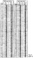
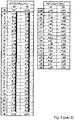
- Figure 3 gives the coordinate pairs (yp;zp) of the wheel profile section 106.4 of the wheels 106 of the present example in the yp, zp coordinate system as shown in Figure 2 .
- the equivalent conicity EQC of wheel set 105 has a way lower increase over the mileage than the known wheel profile designs. More precisely, the simulated equivalent conicity EQC of the wheel set 105 stays well below the critical threshold of 0.2 (for a high speed rail vehicle as vehicle 101) well beyond a mileage of 400,000 km. This reduced increase in the equivalent conicity leads to a long term driving stability and considerably longer re-profiling intervals.
- the wheel profile of the present example has been designed using a preferred embodiment of the method according to the invention.
- the method comprises specifying the components of the wheel unit such as the rim section 106.1, in particular the general dimensions of the rim section 106.1, such as the rim width RW and the radius TSR at the tread datum plane TDP.
- the method further comprises specifying that the rim section 106.1 has a sectional contour in the wheel profile section 106.4 with a flange section FLS, a fillet section FIS and a tread section TS configured to contact a rail 107 of track T in the contact location CL during normal operation of the wheel 106.
- the method further comprises specifying that the tread section TS, in an unworn or re-profiled state, comprises a non-cylindrical contour section NCYS and cylindrical contour section CYS, wherein the cylindrical contour section, along the rolling axis 106.2, has an inner end 106.6, an outer end 106.6 and a cylindrical contour width CCW between the inner end 106.6 and the outer end 106.6.
- the method in particular, further comprises specifying that the cylindrical contour section CYS is located such that, along the rolling axis 106.2, one of the inner end 106.6 and the outer end 106.6 has an end distance EDCY from the tread datum plane TDP which is at most 50% of the cylindrical contour width.
- the method may further comprise specifying that the cylindrical contour section intersects the tread datum plane TDP.
- the method further comprises specifying a geometry of the fillet section FIS using a transfer function TF.
- TF transfer function
- the transfer function TF is created as a function of a geometry of the track T, in particular a curve radius distribution along the track T.
- the transfer function TF is created as a function of a geometry of a rail head 107.1 of the rail 107.
- the transfer function TF is created as a function of an inclination of the rail 107, in particular, of a web 107.2 of the rail 107, with respect to a wheel-rail contact plane WRCP defined by the track T at a given location along the track T.
- the transfer function TF is created as a function of a deformation of the wheel shaft 105.2 connecting the wheels 106 and, hence, their rim sections 106.1, the deformation resulting from a nominal load of the rail vehicle 101.
- the transfer function may be created as a function of a stiffness, in particular, the longitudinal stiffness along the longitudinal direction (x axis) of the rail vehicle 101, of the primary suspension device 104.1.
- a particularly favorable wheel profile design which is tailor made to the intended use of the wheels 106 and the wheel set 105 within a particular rail vehicle 101 to be operated on a particular track T with a given track profile TP.
Landscapes
- Engineering & Computer Science (AREA)
- Mechanical Engineering (AREA)
- Tires In General (AREA)
Abstract
Description
- The present invention relates to a wheel unit for a rail vehicle having a nominal speed above 140 km/h, in particular, a high-speed rail vehicle, the wheel unit comprising a rim section, wherein the rim section defines a rolling axis of the wheel, a rim width along the rolling axis and a tread datum plane perpendicular to the rolling axis. The rim section has a sectional contour in a sectional plane comprising the rolling axis, wherein the sectional contour comprises a wheel profile section. The wheel profile section comprises a flange section and a tread section, wherein the tread section is configured to contact a rail of a track in a contact location during normal operation of the wheel unit. The tread section, in an unworn or re-profiled state, comprises a non-cylindrical contour section. The present invention further relates to a corresponding wheel set comprising two such wheel units, to a corresponding running gear for a rail vehicle comprising such a wheel set as well as a corresponding rail comprising such a running gear. The present invention further relates to a method for designing a wheel unit.
- Wheel units as described above are well known in the art and all share the common feature of a continuously curved wheel profile to achieve favorable wheel-to-rail contact conditions. An example of such a wheel profiles is the widely used profile referred to as "S1002" profile or the commonly used "EPS" profile as described in DIN EN 13715. In order to reduce wear of the wheels and, thus, an undesired wear-induced increase in the so called equivalent conicity (which is a commonly used parameter to define the dynamic behavior of a wheel set)
EP 0 760 294 A2 describes wheel units referred to as "DBS-320", "DBS-315", "DBS-310" and "DBS-305", which are modified variants of the "S1002" profile in terms of curvature. Furthermore,DE 10 2006 034 896 B4 - Despite all these attempts, these prior art wheel units are highly susceptible to alterations of the wheel-to-rail contact and exhibit an adverse wear behavior which causes a more or less rapid increase in the equivalent conicity over time. Such an increase in the equivalent conicity results in an increase in the frequency of the hunting motion of the wheel set along the track and, ultimately, an increased risk of instability of the running gear, which is especially critical for vehicles running at high nominal speeds. Hence, such instability has to be avoided under any circumstances during operation, such that re-profiling has to occur well before any such instability might occur. This considerably reduces the available mileage (before re-profiling has to occur) and, consequently, the re-profiling interval of the respective wheel units.
- Thus, it is the object of the present invention to provide a wheel unit as described above, which does not show the disadvantages described above, or at least shows them to a lesser extent, and, in particular, exhibits a more favorable wear behavior which allows for longer re-profiling intervals.
- The above objects are achieved starting from a wheel unit according to the preamble of
claim 1 by the features of the characterizing part ofclaim 1 as well as starting from a method for designing a wheel unit according to the preamble ofclaim 15 by the features of the characterizing part ofclaim 15. - The present invention is based on the technical teaching that an improved wear behavior of the tread section and a slower wear-induced increase in the equivalent conicity can be accomplished, respectively, if the tread section comprises a cylindrical contour section. Such a cylindrical contour section of the tread section has the beneficial effect that, at least during operation at a nominal speed on a straight level track, an indifferent contact location behavior with a statistical distribution (over time) of the contact location along the rolling axis prevails over the cylindrical contour section. With such a design with at least one cylindrical contour section, at least during operation at a nominal speed on a straight level track, not least due to the statistical distribution of the contact location, an indifferent wear behavior with a statistical distribution of wear of the tread section along the rolling axis prevails over the cylindrical contour section.
- It will be appreciated that, preferably, the cylindrical contour section is a continuous contour section. Nevertheless, with certain embodiments, two or more cylindrical areas of the cylindrical contour section may be separated by (one or more) slightly non-cylindrical spaces, as long as the above indifferent contact loaction behavior and/or the above indifferent wear behavior is achieved over the cylindrical contour section.
- It will be appreciated that, ultimately, such improved contact behavior and wear behavior, respectively, and such reduced increase in the equivalent conicity leads to a long term driving stability and longer re-profiling intervals.
- Hence, according to one aspect, the present invention relates to a wheel unit for a rail vehicle having a nominal speed above 140 km/h, in particular, a high-speed rail vehicle, wherein the wheel unit comprises a rim section and the rim section defines a rolling axis of the wheel, a rim width along the rolling axis and a tread datum plane perpendicular to the rolling axis. The rim section has a sectional contour in a sectional plane comprising the rolling axis, wherein the sectional contour comprises a wheel profile section. The wheel profile section comprises a flange section and a tread section, wherein the tread section is configured to contact a rail of a track in a contact location during normal operation of the wheel unit. The tread section, in an unworn or re-profiled state, comprises a non-cylindrical contour section. The tread section, in an unworn or re-profiled state, further comprises a cylindrical contour section. The cylindrical contour section, along the rolling axis, has an inner end, an outer end and a cylindrical contour width between the inner end and the outer end. The cylindrical contour section is located such that, along the rolling axis, one of the inner end and the outer end has an end distance from the tread datum plane which is at most 50% of the cylindrical contour width. In particular, the cylindrical contour section may intersect the tread datum plane.
- In principle, in particular as a function of the ratio between curved sections of the track and straight sections of the track on which the wheel is intended to run, any desired and suitable location may be chosen for the inner end and the outer end of the cylindrical contour section and, hence, any suitable cylindrical contour width may be chosen.
- Preferably, the end distance is 0% to 50%, preferably 10% to 40%, more preferably 20% to 30%, of the cylindrical contour width. In addition or as alternative, the end distance is 0 mm to 30 mm, preferably 5 mm to 25 mm, more preferably 5 mm to 10 mm. In addition or as alternative the inner end of the cylindrical contour section has the end distance from the tread datum plane. In addition or as an alternative the inner end is located between the flange section and the tread datum plane. In any of these cases particularly favorable indifferent contact location behavior and a favorable indifferent wear behavior, respectively, may be achieved over the cylindrical contour section.
- With certain favorable variants, the cylindrical contour width is at least 4%, preferably at least 7%, more preferably at least 10%, of the rim width. In addition or as an alternative the cylindrical contour width is at least 5 mm, preferably at least 10 mm, more preferably at least 15 mm. In addition or as an alternative the cylindrical contour width is at most 14%, preferably at most 16%, more preferably at most 18%, of the rim width. In addition or as an alternative, the cylindrical contour width is at most 20 mm, preferably at most 22 mm, more preferably at most 25 mm. In any of these cases particularly favorable indifferent contact location behavior and a favorable indifferent wear behavior, respectively, may be achieved over a sufficiently large cylindrical contour section.
- With particularly favorable configurations exhibiting suitably indifferent behavior, the geometry of the cylindrical contour section is kept within certain favorable tolerances. These tolerances may depend on either of the material or material combination of the wheel and the rail, the track profile of the track (on which the wheel is to be used,), the operational parameters of the vehicle (in particular, nominal load, nominal speed etc.), manufacturing tolerances or any other parameter of noticeable influence as well as any combinations of these. Preferably, the cylindrical contour section, over the cylindrical contour width, has a deviation from an ideally cylindrical contour, wherein the deviation is such that a local inclination of the cylindrical contour section with respect to the ideally cylindrical contour is less than 1/200, preferably less than 1/250, more preferably less than 1/300.
- It will be appreciated that, apart from the cylindrical contour section, basically any desired and suitable wheel profile section geometry may be chosen. With certain preferred embodiments showing particularly favorable curve behavior, the wheel profile section comprises an at least partially curved fillet section (sometimes also referred to as the flange root section) which is located between the flange section and the inner end of the cylindrical contour section. The fillet section is preferably configured such that, at least in an unworn or re-profiled state, upon a lateral displacement of the rim section on the rail along the rolling axis during normal operation, the contact location continuously shifts over the fillet section. In addition or as an alternative, the fillet section is configured such that, at least in an unworn or re-profiled state, upon a lateral displacement of the rim section on the rail along the rolling axis at any time during normal operation on a straight track, the contact location forms the single coherent contact location between the rim section and the rail. By any of these means, particularly favorable wear behavior as well as particularly favorable curve behavior may be achieved.
- The fillet section is preferably configured as a function of a geometry of the track on which the wheel unit is intended to be operated, in particular as a function of a curve radius distribution along the track. In addition or as an alternative, the fillet section may be configured as a function of a geometry of a rail head of the rail. In addition or as an alternative, the fillet section may be configured as a function of an inclination of the rail, in particular, as a function of a web of the rail, with respect to a wheel-rail contact plane defined by the track at a given location along the track. In addition or as an alternative, the fillet section may be configured as a function of a deformation of a wheel unit shaft connected to the rim section, the wheel unit shaft defining the rolling axis, and the deformation resulting from a nominal load of the rail vehicle. In addition or as an alternative, the fillet section may be configured as a function of a stiffness, in particular, a longitudinal stiffness (along a longitudinal direction of the rail vehicle), of a primary suspension device connecting the wheel unit to the rail vehicle. It will be appreciated that, in addition or as an alternative, any parameter of the track and/or the vehicle having an influence of the hunting motion and wear behavior of the wheel may be used in configuring the fillet section. In addition or as an alternative, at least a part of the fillet section located adjacent to the cylindrical contour section may continuously change its curvature along the rolling axis. These approaches, either alone or in arbitrary combination, allow achieving a particularly favorable wheel profile design which is tailor made to the intended use of the wheel unit within a particular rail vehicle to be operated on a particular track with a given track profile.
- With preferred variants, the wheel profile section, in an unworn or re-profiled state, defines a flange thickness point, an inner active contact area, an inner active contact area width along the rolling axis, and an inner active contact area contour length. The flange thickness point is used to define a flange thickness along the rolling axis. Depending on the applicable standard for the rail vehicle, there may be different definitions for this flange thickness point. Typically, the flange thickness point is located at an outer side of the flange section at a radius which corresponds to a radius of the wheel profile section in the tread datum plane plus 10 mm. The inner active contact area is confined by the flange thickness point and the tread datum plane, wherein the inner active contact area contour length (i.e. the length of the inner active contact area along the sectional contour) is 105% to 120%, preferably 107% to 115%, more preferably 108% to 110%, of the inner active contact area width.
- It will be appreciated that the inner active contact area contour length may vary depending on the track profile of the track on which the wheel is to be used. In particular, it may vary depending on the ratio of narrow curves (i.e. curves with a radius below a certain critical threshold) within the track.
- Hence, with certain variants, the track may have a track profile with a ratio of curved sections of the track with curve radii of less than 1000 m, which is above 15%, preferably above 20%, more preferably above 25%. Here, the inner active contact area contour length may be 105% to 108%, preferably 105% to 107%, more preferably 105% to 106%, of the inner active contact area width. Hence, in these cases a wheel profile may be achieved which is particularly suitable for operation on tracks with (comparatively) many narrow curves.
- In other cases, the track may have a track profile with a ratio of curved sections of the track with curve radii of less than 1000 m, which is below 15%, preferably below 10%, more preferably below 5%. Here, the inner active contact area contour length may be 108% to 120%, preferably 108% to 115%, more preferably 109% to 110%, of the inner active contact area width. Hence, in these cases a wheel profile may be achieved which is particularly suitable for operation on tracks with (comparatively) few curves as is typically the case for high speed tracks.
- With many variants the flange thickness point is located in close proximity to a conical flange area of the flange section. The conical flange area faces the tread datum plane and defines a flange angle of the flange section. This flange angle typically may range from 65° to 75°, preferably from 67° to 72°, more preferably may be 70°. The wheel profile section defines a transition point, which is located at the end of the conical flange area that is located closer to the tread datum plane. At this transition point, the angle of inclination of a tangent to the sectional contour becomes smaller than the flange angle. It will be appreciated that, with certain variants (in general and irrespective of the overall design of the wheel), this transition point may replace the flange thickness point in defining the inner active contact area, the inner active contact area width, and the inner active contact area contour length as described above.
- Hence, with preferred variants, the wheel profile section, in an unworn or re-profiled state, defines the above transition point, the inner active contact area, the inner active contact area width along the rolling axis, and the inner active contact area contour length. The inner active contact area, here, is confined by the transition point and the tread datum plane, wherein the inner active contact area contour length (i.e. the length of the inner active contact area along the sectional contour) is 105% to 120%, preferably 107% to 115%, more preferably 108% to 110%, of the inner active contact area width.
- It will be appreciated that, again, the inner active contact area contour length may vary depending on the track profile of the track on which the wheel is to be used. In particular, it may vary depending on the ratio of narrow curves (i.e. curves with a radius below a certain critical threshold) within the track.
- Hence, with certain variants, the track may have a track profile with a ratio of curved sections of the track with curve radii of less than 1000 m, which is above 15%, preferably above 20%, more preferably above 25%. Here, the inner active contact area contour length may be 105% to 108%, preferably 105% to 107%, more preferably 105% to 106%, of the inner active contact area width. Hence, in these cases a wheel profile may be achieved which is particularly suitable for operation on tracks with (comparatively) many narrow curves.
- In other cases, the track may have a track profile with a ratio of curved sections of the track with curve radii of less than 1000 m, which is below 15%, preferably below 10%, more preferably below 5%. Here, the inner active contact area contour length may be 108% to 120%, preferably 108% to 115%, more preferably 109% to 110%, of the inner active contact area width. Hence, in these cases a wheel profile may be achieved which is particularly suitable for operation on tracks with (comparatively) few curves as is typically the case for high speed tracks.
- With certain variants exhibiting favorably smooth operation on track switches, the wheel profile section, in an unworn or re-profiled state, has a first conical section located on an outer side of the rim section opposite to the flange section, the first conical section having an inner first end, an outer second end and a first inclination with respect to the rolling axis. The inner first end is located at a first distance from the tread datum plane, the first distance being 4% to 23%, preferably 4% to 15%, more preferably 4% to 8%, of the rim width. In addition or as an alternative, the first distance is 5 mm to 30 mm, preferably 5 mm to 20 mm, more preferably 5 mm to 10 mm. Additionally or as an alternative, the outer second end is located at a second distance from the tread datum plane, the second distance being 8% to 30%, preferably 11% to 26%, more preferably 15% to 22%, of the rim width. In addition or as an alternative, the second distance is 10 mm to 40 mm, preferably 15 mm to 35 mm, more preferably 20 mm to 30 mm. Additionally or as alternative, the first inclination is 1/45 to 1/15, preferably 1/43 to 1/32, more preferably 1/40 to 1/35.
- It will be appreciated that, basically, a single conical section may be sufficient to achieve the above effect of smooth track switch operation. With certain variants showing even better behavior, in particular better track switch operation, however, the wheel profile section, in an unworn or re-profiled state, has a second conical section located on an outer side of the first conical section opposite to the flange section, the second conical section having an inner third end, an outer fourth end and a second inclination with respect to the rolling axis, the inner third end, in particular, substantially coinciding with the outer second end of the first conical section. The inner third end is located at a third distance from the tread datum plane, the third distance being 8% to 30%, preferably 11% to 26%, more preferably 15% to 22%, of the rim width. In addition or as an alternative, the third distance is 10 mm to 40 mm, preferably 15 mm to 35 mm, more preferably 20 mm to 30 mm. Additionally or as an alternative, the outer fourth end is located at a fourth distance from the tread datum plane, the fourth distance is 33% to 48%, preferably 37% to 46%, more preferably 41% to 44%, of the rim width. In addition or as an alternative, the fourth distance is 45 mm to 65 mm, preferably 50 mm to 62 mm, more preferably 55 mm to 60 mm. Additionally or as an alternative, the second inclination is 1/25 to 1/8, preferably 1/20 to 1/9, more preferably 1/15 to 1/10. Preferably, the second inclination is higher than the first inclination.
- It will be appreciated that the wheel unit may be used for any desired nominal operating speed. Preferably, the wheel unit is configured for use at a nominal speed above 160 km/h, preferably above 180 km/h, more preferably above 200 km/h, more preferably above 250 km/h, more preferably above 300 km/h. Here, the above effects of statistically distributed wear are particularly advantageous.
- It will be appreciated that, in principle, any desired wheel design may be used for the wheel unit, such as monolithic wheels or multi-component wheels. Typically, the wheel unit comprises a web section connecting the rim section to a hub section of the wheel unit. However, any other design may be used as well.
- The present invention further relates to a wheel set comprising two wheel units according to the invention, wherein each of the two wheel units is configured to contact a rail of the track. It will be appreciated that the two wheel units of the wheel set are typically connected by a common wheel set shaft which preferably provides a torsionally rigid connection between the two wheel units, such that both wheel units rotate at the same speed. With other variants, however, it is also possible that this rotational speed coupling between the two wheel units is achieved by different means, such as e.g. a gear unit, to achieve the dynamic behavior of a wheel set.
- The wheel units and the rails, in a state of the wheel set which is displaced along the rolling axis by 3 mm with respect to a nominally central position on the rails, define an equivalent conicity of the wheel set and the equivalent conicity preferably ranges from 0 to 1/100, preferably from 0 to 1/150, more preferably from 0 to 1/200. With certain variants, the track has a track profile with a ratio of curved sections of the track with curve radii of less than 1000 m, which is above 15%, preferably above 20%, more preferably above 25%. Here, the equivalent conicity may range from 0 to 1/100, preferably from 0 to 1/150, more preferably from 0 to 1/200. Hence, in these cases a wheel profile may be achieved which is particularly suitable for operation on tracks with (comparatively) many narrow curves.
- With other variants, the track has a track profile with a ratio of curved sections of the track with curve radii of less than 1000 m, which is below 15%, preferably below 10%, more preferably below 5%. Here, the equivalent conicity may range from 0 to 1/200, preferably from 0 to 1/300, more preferably from 0 to 1/400. Hence, in these cases a wheel profile may be achieved which is particularly suitable for operation on tracks with (comparatively) few curves as is typically the case for high speed tracks.
- The present invention further relates to a running gear for a rail vehicle, in particular, a high-speed rail vehicle, comprising at least one wheel set according to the invention. The present invention further relates to a rail vehicle, in particular, a high-speed rail vehicle, comprising a wagon body supported on at least one running gear according to the invention. Herewith, the variants and advantages of the present invention may be realized to the same extent, such that, insofar, reference is only made to the above explanations.
- The present invention further relates to a method for designing a wheel unit. The wheel unit is configured for use in a rail vehicle having a nominal speed above 140 km/h, in particular, a high-speed rail vehicle, the wheel unit comprising a rim section. The method comprises specifying that the rim section defines a rolling axis of said wheel, a rim width along the rolling axis and a tread datum plane perpendicular to the rolling axis. The method further comprises specifying that the rim section has a sectional contour in a sectional plane comprising the rolling axis, the sectional contour comprising a wheel profile section with a flange section, a fillet section and a tread section, the tread section being configured to contact a rail of a track in a contact location during normal operation of the wheel unit. The method further comprises specifying that the tread section, in an unworn or re-profiled state, comprises a non-cylindrical contour section. The method further comprises specifying that the tread section, in an unworn or re-profiled state, further comprises a cylindrical contour section, the cylindrical contour section, along the rolling axis, having an inner end, an outer end and a cylindrical contour width between the inner end and the outer end, the cylindrical contour section, in particular, being located such that, along the rolling axis, one of the inner end and the outer end has an end distance from the tread datum plane which is at most 50% of the cylindrical contour width, the cylindrical contour section, in particular, intersecting the tread datum plane. The method further comprises specifying a geometry of the fillet section using a transfer function, the transfer function being created as a function of a geometry of the track, in particular a curve radius distribution along the track. In addition or as an alternative, the transfer function may be created as a function of a geometry of a rail head of the rail. In addition or as an alternative, the transfer function may be created as a function of an inclination of the rail, in particular, of a web of the rail, with respect to a wheel-rail contact plane defined by the track at a given location along the track. In addition or as an alternative, the transfer function may be created as a function of a deformation of a wheel unit shaft connected to the rim section, the wheel unit shaft defining the rolling axis, and the deformation resulting from a nominal load of the rail vehicle. In addition or as an alternative, the transfer function may be created as a function of a stiffness, in particular, a longitudinal stiffness, of a primary suspension device connecting the wheel unit to the rail vehicle. Here as well, these approaches, either alone or in arbitrary combination, allow achieving a particularly favorable wheel profile design which is tailor made to the intended use of the wheel unit within a particular rail vehicle to be operated on a particular track with a given track profile.
- Further embodiments of the present invention will become apparent from the dependent claims and the following description of preferred embodiments which refers to the appended figures.
-
- Figure 1
- is a highly schematic side view of a preferred embodiment of a rail vehicle according to the present invention with a preferred embodiment of a running gear unit according to the present invention comprising a preferred embodiment of a wheel set according to the present invention with a preferred embodiment of a wheel unit according to the present invention designed using a preferred embodiment of a design method according to the present invention.
- Figure 2
- is a sectional view of a part of the wheel unit of
Figure 1 . - Figure 3
- is a table of the wheel unit profile coordinates of the wheel unit of
Figure 1 . - Figure 4
- is a diagram showing the evolution of the equivalent conicity over mileage for wheel set of
Figure 1 compared to known wheel units. - With reference to
Figures 1 to 4 a preferred embodiment of arail vehicle 101 according to the present invention will now be described in greater detail. The rail vehicle 101 (only shown in a highly schematic partially sectional manner inFigure 1 ) is a high speed rail vehicle with a nominal operating speed of 300 km/h and more. - In order to simplify the explanations given below, an xyz-coordinate system has been introduced into the Figures, wherein (on a straight, level track T) the x-axis designates the longitudinal direction of the
rail vehicle 101, the y-axis designates the transverse direction of therail vehicle 101, while the z-axis designates the height direction of therail vehicle 101. It will be appreciated that all statements made in the following with respect to the position and orientation of components of the rail vehicle, unless otherwise stated, refer to a static situation with therail vehicle 101 standing on a straight level track under nominal loading. - The
vehicle 101 comprises a wagon body unit in the form of awagon body 102 supported by a secondary suspension arrangement 104.2 on a running gear unit in the form of abogie 103 with a bogie frame 103.1. Thesecondary suspension arrangement 104 is typically formed by two air springs located in a conventional manner at both lateral sides of thewagon body 102 and supporting thewagon body 102 on the bogie frame 103.1. - Each
bogie 103 comprises twowheel sets 105 according to the present invention. The bogie frame 103.1 is supported on these wheel sets 105 via primary suspension arrangements in the form of primary springs 104.1. In the present example, the wheel sets 105 are internally supported, i.e. supported by bearings located between the longitudinal beams of the bogie frame 103.1. It will be appreciated however that, with other variants, any other support concept may be chosen, e.g. also a so called external support. - Each
wheel set 105 comprises a preferred embodiment of a wheel unit according to the present invention formed by awheel 106. It will be appreciated that the twowheels 106 of therespective wheel set 105, in the present variant, are connected by a common wheel set shaft 105.1 which provides a torsionally rigid connection between the twowheels 106, such that bothwheels 106 rotate at the same speed about a rolling axis 105.2. -
Figure 2 is a sectional view of a lower part of thewheel 106, more precisely, a part of a rim section 106.1 of thewheel 106, contacting arail 107 of track T in a contact location CL during normal operation of thewheel 106 and thevehicle 101, respectively. It will be appreciated that any desired wheel design may be used for thewheel 106, such as monolithic wheels or multi-component wheels. In the present example, thewheel 106 comprises a web section (not shown in greater detail) connecting the rim section 106.1 to a hub section (not shown in greater detail) of thewheel 106, which is then connected to the wheel set shaft 105.1. - As can be seen from
Figure 1 and 2 , the rim section 106.1 ofwheel 106 defines a rolling axis 106.2 of the wheel 106 (coinciding with the rolling axis 105.2 of the wheel set 105), a rim width RW along the rolling axis 106.2 and a tread datum plane TDP perpendicular to the rolling axis 106.2. The rim section 106.1 has a sectional contour 106.3 in a sectional plane comprising the rolling axis 106.2 (see drawing plane ofFigure 2 ). The sectional contour 106.3 comprises a wheel profile section 106.4. The wheel profile section 106.4, from an inner side of the wheel 106 (facing the wheel set center) to an outer side of thewheel 106, comprises a flange section FLS, a fillet section FIS, a tread section TS, and an outer wheel section OWS. - The tread section TS configured to contact the
rail 107 in a contact location CL. It will be appreciated that the contact location CL varies over time dependent on the dynamic loads acting on thevehicle 101 and the resulting lateral displacement (in the lateral direction, i.e. along the y axis). It will be further appreciated that the fillet section FIS partially overlaps the tread section TS. Hence, during normal operation, the part of the fillet section FIS overlapping the tread section TS also contacts the rail 107 (upon sufficient lateral displacement). - The tread section TS, in an unworn or re-profiled state, comprises a non-cylindrical contour section NCYS formed by the overlapping part of the fillet section FIS. The tread section TS, in an unworn or re-profiled state, further comprises a cylindrical contour section CYS located adjacent to the fillet section FIS. The cylindrical contour section CYS, along the rolling axis 106.2, has an inner end 106.5, an outer end 106.6 and a cylindrical contour width CCW between the inner end 106.5 and the outer end 106.6. The cylindrical contour section CYS is located such that, along the rolling axis 106.2, it intersects the tread datum plane TDP. The inner end 106.5 of the cylindrical contour section CYS is located between the flange section FLS and the tread datum plane TDP, wherein it has an end distance EDCY = 0.117 mm from the tread datum plane TDP (see also
Figure 3 ). - However, in further preferred variants, the inner end 106.5 has an end distance EDCY from the tread datum plane TDP which is at most 50% of the cylindrical contour width. In other preferred variants, in particular as a function of the ratio between curved sections of the track T and straight sections of the track T on which the
wheel set 105 is intended to run, any desired and suitable location may be chosen for the inner end 106.5 and the outer end 106.6 of the cylindrical contour section CYS and, hence, any suitable cylindrical contour width CCW may be chosen. - The end distance EDCY is about 1.2% of the cylindrical contour width CCW. However, in other preferred variants, the end distance EDCY may be 0% to 50%, preferably 10% to 40%, more preferably 20% to 30%, of the cylindrical contour width. In further preferred variants, the end distance EDCY may be 0 mm to 30 mm, preferably 5 mm to 25 mm, more preferably 5 mm to 10 mm. In further preferred variants, it is also possible that the outer end 106.6 of the cylindrical contour section CYS has the end distance EDCY from the tread datum plane TDP as described above.
- In any of these cases particularly favorable indifferent contact location behavior and favorable indifferent wear behavior, respectively, may be achieved thanks to the cylindrical contour section CYS. As noted above, the cylindrical contour section CYS has the beneficial effect that, at least during operation of the
vehicle 101 at its nominal speed on a straight level track T, a statistical distribution (over time) of the contact location CL along the rolling axis 106.2 prevails over the cylindrical contour section CYS. Moreover, with such a cylindrical contour section CYS, not least due to the statistical distribution of the contact location CL, an indifferent wear behavior with a statistical distribution of wear of the tread section TS along the rolling axis 106.2 prevails over the cylindrical contour section CYS. - In the present variant, the cylindrical contour width CCW is about 7.5% of a rim width RW of the rim section 106.1 along the rolling axis 106.2. However, in further preferred variants, the cylindrical contour width CCW may be at least 4%, preferably at least 7%, more preferably at least 10%, of the rim width RW. The cylindrical contour width CCW is 10.117 mm (see also
Figure 3 ). However, in further preferred variants, the cylindrical contour width CWW may be at least 5 mm, preferably at least 10 mm, more preferably at least 15 mm. In further preferred variants, the cylindrical contour width CWW may be chosen to be at most 14%, preferably at most 16%, more preferably at most 18%, of the rim width RW. Finally, the cylindrical contour width CWW may be chosen to be at most 20 mm, preferably at most 22 mm, more preferably at most 25 mm. With any of the above width dimensions of the cylindrical contour section CYS particularly favorable indifferent contact location behavior and a favorable indifferent wear behavior, respectively, may be achieved over a sufficiently large cylindrical contour section CYS. - It will be appreciated that the cylindrical contour section CYS does not have to be perfectly cylindrical. Hence, with favorable configurations still exhibiting suitably indifferent behavior, the geometry of the cylindrical contour section CYS is kept within certain favorable tolerances. These tolerances may depend on either of the material or material combination of the
wheel 106 and themating rail 107, the track profile of the track T (on which thewheel 106 is to be used), the operational parameters of the vehicle 101 (in particular, nominal load, nominal speed etc.), manufacturing tolerances or any other parameter of noticeable influence as well as any combinations of these parameters. - In the present example, the cylindrical contour section CYS, over the cylindrical contour width CCW, has a deviation CYD from an ideally cylindrical contour ICC. The deviation CYD is such that a local inclination LIC with respect to the ideally cylindrical contour ICC is less than 1/200. In other preferred variants, in addition or as an alternative, the cylindrical contour section CYS, over the cylindrical contour width CCW, may have a deviation CYD from the ideally cylindrical contour ICC is such that the local inclination with respect to the ideally cylindrical contour ICC is less than 1/250, more preferably less than 1/300.
- In the present example, the cylindrical contour section CYS is a continuous section along the rolling axis 106.2. It will be appreciated that, with certain variants, two or more cylindrical areas of the cylindrical contour section CYS may be separated by (one or more) slightly non-cylindrical spaces, as long as the above indifferent contact loaction behavior and/or the above indifferent wear behavior is still substantially achieved over the cylindrical contour section CYS.
- It will be appreciated that, apart from the cylindrical contour section CYS, basically any desired and suitable wheel profile section geometry may be chosen. In the present example, the wheel profile section comprises the partially curved fillet section, which is configured such that, at least in an unworn or re-profiled state, upon a (sufficiently large) lateral displacement LD of the rim section 106.1 on the
rail 107 along the rolling axis105.2 during normal operation, the contact location CL continuously shifts over the fillet section FIS. By this means, particularly favorable wear behavior as well as particularly favorable curve behavior is achieved for thewheel set 105. - The fillet section FIS is further configured such that, at least in an unworn or re-profiled state, upon a lateral displacement LD of the rim section 106.1 on the
rail 107 along the rolling axis 105.2 at any time during normal operation on a straight track, the contact location CL forms the single coherent contact location between the rim section 106.1 and therail 107. By this means as well, particularly favorable wear behavior as well as particularly favorable curve behavior may is achieved for thewheel set 105. - In the present example, the above continuous shift of the contact location CL and the single coherent contact location behavior are achieved in that at least a part of the fillet section FIS located adjacent to the cylindrical contour section CYS continuously changes its curvature along the rolling axis 105.2.
- In the present example, the fillet section FIS has been configured as a function of a geometry of the particular track T on which the
wheel 106 is intended to be operated. In particular, the fillet section FIS has been configured as a function of a curve radius distribution CRD along the track T. Also, the fillet section FIS has been configured as a function of a geometry of the rail head 107.1 of therail 107. Additionally, the fillet section FIS has been configured as a function of an inclination of therail 107, in particular, as a function of the web 107.2 of therail 107, with respect to a wheel-to-rail contact plane WRCP defined by the track T at a given location along the track T. The fillet section FIS has further been configured as a function of the deformation of the wheel set shaft 105.1 resulting from a nominal load of therail vehicle 101. This design approach allows achieving a particularly favorable wheel profile design which is tailor made to the intended use of thewheel 106 within therail vehicle 101 to be operated on the track T with a given track profile TP. - The wheel profile section 106.4, in an unworn or re-profiled state, defines a flange thickness point FLTP used to define a flange thickness FLT along the rolling axis 106.2. Depending on the applicable standard for the
rail vehicle 101, there may be different definitions or locations, respectively, which are applicable for this flange thickness point FLTP. Typically, the flange thickness point FLTP is located at an outer side of the flange section FLS at a radius which corresponds to a radius of the wheel profile section in the tread datum plane plus 10 mm (as shown inFigure 2 ). - The wheel profile section 106.4, in such an unworn or re-profiled state, further defines an inner active contact area IACA, an inner active contact area width IACAW along the rolling axis 106.2, and an inner active contact area contour length IACAL. The inner active contact area contour length IACAL is the length of the inner active contact area IACA along the sectional contour 106.3. The inner active contact area IACA is confined by the flange thickness point FLTP and the tread datum plane TDP. The inner active contact area contour length IACAL, in the present example, is 109.5%, of the inner active contact area width IACAW. With other variants, the inner active contact area contour length IACAL may be 105% to 120%, preferably 107% to 115%, more preferably 108% to 110%, of the inner active contact area width IACAW.
- It will be appreciated that the inner active contact area contour length IACAL may vary depending on the track profile TP of the track T on which the
wheel 106 is to be used. In particular, it may vary depending on the ratio of narrow curves (i.e. curves with a radius below a certain critical threshold) within the track T. - Hence, with certain variants, the track T may have a track profile TP with a ratio of curved sections of the track with curve radii of less than 1000 m, which is above 15%, preferably above 20%, more preferably above 25%. Here, the inner active contact area contour length IACAL may be 105% to 108%, preferably 105% to 107%, more preferably 105% to 106%, of the inner active contact area width. Hence, in these cases a wheel profile may be achieved which is particularly suitable for operation on tracks T with (comparatively) many narrow curves.
- In other cases, as with the present example, the track T may have a track profile TP with a ratio of curved sections of the track T with curve radii of less than 1000 m, which is below 15%, preferably below 10%, more preferably below 5%. Here, the inner active contact area contour length IACAL may be 108% to 120%, preferably 108% to 115%, more preferably 109% to 110%, of the inner active contact area width IACAW. Hence, in these cases a wheel profile may be achieved which is particularly suitable for operation on tracks with (comparatively) few curves as is typically the case for high speed tracks, like the track T on which the
vehicle 101 is to be used. - As can be seen from
Figure 2 , the flange thickness point FLTP, in the present example, is located in close proximity to a conical flange area CFLA of said flange section FLS. The conical flange area CFLA faces the tread datum plane TDP and defines a flange angle FLA of the flange section FLS. This flange angle FLA typically may range from 65° to 75°, preferably from 67° to 72°, more preferably may be 70°. At a transition point, which is located at the end of the conical flange area CFLA that is located closer to the tread datum plane TDP (than the other end of the conical flange area CFLA), the angle of inclination of a tangent to the sectional contour 106.3 becomes smaller than the flange angle FLA. It will be appreciated that, with certain variants (in general and irrespective of the overall design of the wheel 106), this transition point may replace the flange thickness point in defining the inner active contact area IACA, the inner active contact area width IACAW, and the inner active contact area contour length IACAL as described above. - To exhibit favorably smooth operation on track switches of the track T, the wheel profile section 106.4 of the present example, in an unworn or re-profiled state, has a first conical section CNS1 of the outer wheel section OWS, which is located on an outer side of the rim section 106.1 opposite to the flange section FLS. The first conical section CNS1 has an inner first end coinciding with the outer end 106.6 of the cylindrical contour section CYS, an outer second end 106.7 and a first inclination INC1 with respect to the rolling axis 106.2. The inner first end 106.6 is located at a first distance D1 = 11 mm from the tread datum plane TDP. It will be appreciated that, with other variants, the first distance D1 may be 4% to 23%, preferably 4% to 15%, more preferably 4% to 8%, of the rim width RW. In addition or as an alternative, the first distance D1 may be 5 mm to 30 mm, preferably 5 mm to 20 mm, more preferably 5 mm to 10 mm.
- Furthermore, the outer second end 106.7 is located at a second distance D2 = 29 mm from the tread datum plane TDP. It will be appreciated that, with further variants, the second distance D2 may be 8% to 30%, preferably 11% to 26%, more preferably 15% to 22%, of the rim width RW. In addition or as an alternative, the second distance D2 may be 10 mm to 40 mm, preferably 15 mm to 35 mm, more preferably 20 mm to 30 mm. Moreover, the first inclination may be 1/45 to 1/15, preferably 1/43 to 1/32, more preferably 1/40 to 1/35.
- It will be appreciated that, basically, a single conical section CNS1 may be sufficient to achieve the above effect of smooth track switch operation. The present example, however, shows even better behavior, in particular better track switch operation, since the wheel profile section 106.4, in an unworn or re-profiled state, has a second conical section CNS2 located on the outer side of the first conical section CNS1 opposite to the flange section FLS. The second conical section CNS2 has an inner third end coinciding with the outer end 106.7 of the first conical section CNS1, an outer fourth end 106.8 and a second inclination INC2 with respect to the rolling axis 106.2.
- The inner third end 106.7 end is located at a third distance D3 = D2 = 29 mm from the tread datum plane TDP. It will be appreciated that, with further variants, the third distance may be 8% to 30%, preferably 11% to 26%, more preferably 15% to 22%, of the rim width RW. In addition or as an alternative, the third distance may be 10 mm to 40 mm, preferably 15 mm to 35 mm, more preferably 20 mm to 30 mm. Additionally or as an alternative, the outer fourth end 106.8 is located at a fourth distance D4 from the tread datum plane D4, the fourth distance may be 33% to 48%, preferably 37% to 46%, more preferably 41% to 44%, of the rim width RW. In addition or as an alternative, the fourth distance may be 45 mm to 65 mm, preferably 50 mm to 62 mm, more preferably 55 mm to 60 mm. Moreover, the second inclination INC2 is 1/25 to 1/8, preferably 1/20 to 1/9, more preferably 1/15 to 1/10. Preferably, the second inclination is higher than the first inclination.
- In the present example, the
wheels 106 of therespective wheel set 105 and therails 107 of the track T, in a state of thewheel set 105 which is displaced along the rolling axis 105.2, 106.2 (i.e. along the y axis) by 3 mm with respect to a nominally central position (as shown inFigure 2 ) on therails 107 of the track T, define an equivalent conicity EQC of thewheel set 105. This equivalent conicity EQC, in the present example, is substantially EQC = 0. It will be appreciated that, with other variants, the equivalent conicity EQC preferably ranges from 0 to 1/100, preferably from 0 to 1/150, more preferably from 0 to 1/200. - With certain variants, the track T has a track profile TP with a ratio of curved sections of the track T with curve radii of less than 1000 m, which is above 15%, preferably above 20%, more preferably above 25%. Here, the equivalent conicity EQC may range from 0 to 1/100, preferably from 0 to 1/150, more preferably from 0 to 1/200. Hence, in these cases a wheel profile may be achieved which is particularly suitable for operation on tracks with (comparatively) many narrow curves.
- With other variants, as with the present example, the track T has a track profile TP with a ratio of curved sections of the track T with curve radii of less than 1000 m, which is below 15%, preferably below 10%, more preferably below 5%Here, the equivalent conicity EQC may range from 0 to 1/200, preferably from 0 to 1/300, more preferably from 0 to 1/400. Hence, in these cases a wheel profile may be achieved which is particularly suitable for operation on tracks T with (comparatively) few curves as is typically the case for high speed tracks, like the track T on which the
vehicle 101 is to be used.. - As noted,
Figure 3 gives the coordinate pairs (yp;zp) of the wheel profile section 106.4 of thewheels 106 of the present example in the yp, zp coordinate system as shown inFigure 2 . - The advantages of the present invention become readily apparent from
Figure 4 , showing theequivalent conicity curve 108 for the simulated development of the equivalent conicity EQC over the mileage for thewheel set 105 and the corresponding equivalent conicity curves 109.1 to 109.3 of three comparison wheel sets. The equivalent conicity curves 109.1 and 109.2 were determined for variants of the known "S1002" profile, namely "S1002e315" and "S1002 e325", while the equivalent conicity curve 109.3 was determined for a variant of the known "EPS" profile, namely "EPS e305". - As can be clearly seen from
Figure 4 , thanks to the improved, indifferent contact behavior and wear behavior, respectively, the equivalent conicity EQC ofwheel set 105 has a way lower increase over the mileage than the known wheel profile designs. More precisely, the simulated equivalent conicity EQC of thewheel set 105 stays well below the critical threshold of 0.2 (for a high speed rail vehicle as vehicle 101) well beyond a mileage of 400,000 km. This reduced increase in the equivalent conicity leads to a long term driving stability and considerably longer re-profiling intervals. - The wheel profile of the present example has been designed using a preferred embodiment of the method according to the invention. The method comprises specifying the components of the wheel unit such as the rim section 106.1, in particular the general dimensions of the rim section 106.1, such as the rim width RW and the radius TSR at the tread datum plane TDP.
- The method further comprises specifying that the rim section 106.1 has a sectional contour in the wheel profile section 106.4 with a flange section FLS, a fillet section FIS and a tread section TS configured to contact a
rail 107 of track T in the contact location CL during normal operation of thewheel 106. - The method further comprises specifying that the tread section TS, in an unworn or re-profiled state, comprises a non-cylindrical contour section NCYS and cylindrical contour section CYS, wherein the cylindrical contour section, along the rolling axis 106.2, has an inner end 106.6, an outer end 106.6 and a cylindrical contour width CCW between the inner end 106.6 and the outer end 106.6. The method, in particular, further comprises specifying that the cylindrical contour section CYS is located such that, along the rolling axis 106.2, one of the inner end 106.6 and the outer end 106.6 has an end distance EDCY from the tread datum plane TDP which is at most 50% of the cylindrical contour width. The method may further comprise specifying that the cylindrical contour section intersects the tread datum plane TDP.
- The method further comprises specifying a geometry of the fillet section FIS using a transfer function TF. With such a transfer function, the influences of the track T on the dynamic loads and the resulting wear behavior can be simulated and properly considered when designing the wheel profile of the
wheels 106. - In the present example, the transfer function TF is created as a function of a geometry of the track T, in particular a curve radius distribution along the track T. In addition, the transfer function TF is created as a function of a geometry of a rail head 107.1 of the
rail 107. In addition, the transfer function TF is created as a function of an inclination of therail 107, in particular, of a web 107.2 of therail 107, with respect to a wheel-rail contact plane WRCP defined by the track T at a given location along the track T. In addition, the transfer function TF is created as a function of a deformation of the wheel shaft 105.2 connecting thewheels 106 and, hence, their rim sections 106.1, the deformation resulting from a nominal load of therail vehicle 101. In addition, the transfer function may be created as a function of a stiffness, in particular, the longitudinal stiffness along the longitudinal direction (x axis) of therail vehicle 101, of the primary suspension device 104.1. Herewith a particularly favorable wheel profile design which is tailor made to the intended use of thewheels 106 and thewheel set 105 within aparticular rail vehicle 101 to be operated on a particular track T with a given track profile TP. - The present invention, in the foregoing, has only been described in the context of a specific high speed rail vehicle. It will be appreciated, however, that it may also be used in the context of any other rail vehicle operated at different nominal speeds, in particular, any rail vehicle operated at a nominal speed of 140 km/h and above.
Claims (15)
- A wheel unit for a rail vehicle having a nominal speed above 140 km/h, in particular, a high-speed rail vehicle, said wheel unit comprising a rim section, wherein- said rim section (106.1) defines a rolling axis (106.2) of said wheel 106, a rim width along said rolling axis (106.2) and a tread datum plane perpendicular to said rolling axis (106.2),- said rim section (106.1) has a sectional contour (106.3) in a sectional plane comprising said rolling axis (106.2),- said sectional contour (106.3) comprises a wheel profile section (106.4),- said wheel profile section (106.4) comprises a flange section and a tread section,- said tread section is configured to contact a rail (107) of a track in a contact location during normal operation of said wheel unit;- said tread section, in an unworn or re-profiled state, comprises a non-cylindrical contour section;characterized in that- said tread section, in said unworn or re-profiled state, further comprises a cylindrical contour section;- said cylindrical contour section, along said rolling axis (106.2), has an inner end (106.5), an outer end (106.6) and a cylindrical contour width between said inner end (106.5) and said outer end (106.6);- said cylindrical contour section is located such that, along said rolling axis (106.2), one of said inner end (106.5) and said outer end (106.6) has an end distance from said tread datum plane which is at most 50% of said cylindrical contour width, said cylindrical contour section, in particular, intersecting said tread datum plane.
- The wheel unit according to claim 1, wherein- said end distance is 0% to 50%, preferably 10% to 40%, more preferably 20% to 30%, of said cylindrical contour width;
and/or- said end distance is 0 mm to 30 mm, preferably 5 mm to 25 mm, more preferably 5 mm to 10 mm; and/or- said inner end (106.5) has said end distance from said tread datum plane; and/or- said inner end (106.5) is located between said flange section and said tread datum plane. - The wheel unit according to claim 1 or 2, wherein- said cylindrical contour width is at least 4%, preferably at least 7%, more preferably at least 10%, of said rim width;
and/or- said cylindrical contour width is at least 5 mm, preferably at least 10 mm, more preferably at least 15 mm;
and/or- said cylindrical contour width is at most 14%, preferably at most 16%, more preferably at most 18%, of said rim width;
and/or- said cylindrical contour width is at most 20 mm, preferably at most 22 mm, more preferably at most 25 mm; - The wheel unit according to claim 3, wherein- said cylindrical contour section, over said cylindrical contour width, has a deviation from an ideally cylindrical contour, wherein- said deviation is such that a local inclination of said cylindrical contour section with respect to said ideally cylindrical contour is less than 1/200, preferably less than 1/250, more preferably less than 1/300.
- The wheel unit according to any one of claims 1 to 4, wherein- said cylindrical contour section is configured such that, at least during operation at said nominal speed on a straight level track, an indifferent contact point behavior with a statistical distribution of said contact location along said rolling axis (106.2) prevails over said cylindrical contour section;
and/or- said cylindrical contour section is configured such that, at least during operation at said nominal speed on a straight level track, an indifferent wear behavior with a statistical distribution of wear of said tread section along said rolling axis (106.2) prevails over said cylindrical contour section. - The wheel unit according to any one of claims 1 to 5, wherein- said wheel profile section (106.4) comprises an at least partially curved fillet section located between said flange section and said inner end (106.5) of said cylindrical contour section;
wherein- said fillet section is configured such that, at least in said unworn or re-profiled state, upon a lateral displacement of said rim section (106.1) on said rail (107) along said rolling axis (106.2) during normal operation, said contact location continuously shifts over said fillet section;
and/or- said fillet section is configured such that, at least in said an unworn or re-profiled state, upon a lateral displacement of said rim section (106.1) on said rail (107) along said rolling axis (106.2) at any time during normal operation on a straight track, said contact location forms the single coherent contact location between said rim section (106.1) and said rail (107). - The wheel unit according to claim 6, wherein- said fillet section is configured as a function of a geometry of said track, in particular a curve radius distribution along said track,
and/or- said fillet section is configured as a function of a geometry of a rail head (107.1) of said rail (107);
and/or- said fillet section is configured as a function of an inclination of said rail (107), in particular, of a web (107.2) of said rail (107), with respect to a wheel-rail contact plane defined by said track at a given location along said track;
and/or- said fillet section is configured as a function of a deformation of a wheel unit shaft (105.1) connected to said rim section (106.1), said wheel unit shaft (105.1) defining said rolling axis (106.2), and said deformation resulting from a nominal load of said rail vehicle (101).
and/or- said fillet section is configured as a function of a stiffness, in particular, a longitudinal stiffness, of a primary suspension device connecting said wheel unit to said rail vehicle (101).
and/or- at least a part of said fillet section located adjacent to said cylindrical contour section continuously changes its curvature along said rolling axis (106.2). - The wheel unit according to any one of claims 1 to 7, wherein- said wheel profile section (106.4), in said unworn or re-profiled state, defines a flange thickness point and/or a transition point, an inner active contact area, an inner active contact area width along said rolling axis (106.2), and an inner active contact area contour length;- said flange thickness point is used to define a flange thickness along said rolling axis (106.2); said flange thickness point, in particular, being located at an outer side of said flange section at a radius which corresponds to a radius of said wheel profile section (106.4) in said tread datum plane plus 10 mm;- said transition point is located at the end of a conical flange area that is located closer to said tread datum plane;- said inner active contact area is confined by said flange thickness point or said transition point and by said tread datum plane;- said inner active contact area contour length is 105% to 120%, preferably 107% to 115%, more preferably 108% to 110%, of said inner active contact area width
wherein- said track, in particular, has a track profile with a ratio of curved sections of said track with curve radii of less than 1000 m, which is above 15%, preferably above 20%, more preferably above 25%, and said inner active contact area contour length is 105% to 108%, preferably 105% to 107%, more preferably 105% to 106%, of said inner active contact area width
or- said track, in particular, has a track profile with a ratio of curved sections of said track with curve radii of less than 1000 m, which is below 15%, preferably below 10%, more preferably below 5%, and said inner active contact area contour length is 108% to 120%, preferably 108% to 115%, more preferably 109% to 110%, of said inner active contact area width. - The wheel unit according to any one of claims 1 to 8, wherein- said wheel profile section (106.4), in said unworn or re-profiled state, has a first conical section located on an outer side of said rim section (106.1) opposite to said flange section, said first conical section having an inner first end (106.6), an outer second end (106.7) and a first inclination with respect to said rolling axis (106.2);
wherein- said inner first end (106.6) is located at a first distance from said tread datum plane, said first distance being 4% to 23%, preferably 4% to 15%, more preferably 4% to 8%, of said rim width and/or said first distance being 5 mm to 30 mm, preferably 5 mm to 20 mm, more preferably 5 mm to 10 mm;
and/or- said outer second end (106.7) is located at a second distance from said tread datum plane, said second distance being 8% to 30%, preferably 11% to 26%, more preferably 15% to 22%, of said rim width and/or said second distance being 10 mm to 40 mm, preferably 15 mm to 35 mm, more preferably 20 mm to 30 mm;
and/or- said first inclination is 1/45 to 1/15, preferably 1/43 to 1/32, more preferably 1/40 to 1/35. - The wheel unit according to claim 9, wherein- said wheel profile section (106.4), in said unworn or re-profiled state, has a second conical section located on an outer side of said first conical section opposite to said flange section, said second conical section having an inner third end (106.7), an outer fourth end (106.8) and a second inclination with respect to said rolling axis (106.2), said inner third end (106.7), in particular, substantially coinciding with said outer second end (106.7) of said first conical section;
wherein- said inner third end (106.7) is located at a third distance from said tread datum plane, said third distance being 8% to 30%, preferably 11% to 26%, more preferably 15% to 22%, of said rim width and/or said third distance being 10 mm to 40 mm, preferably 15 mm to 35 mm, more preferably 20 mm to 30 mm;
and/or- said outer fourth end (106.8) is located at a fourth distance from said tread datum plane, said fourth distance being 33% to 48%, preferably 37% to 46%, more preferably 41 % to 44%, of said rim width and/or said fourth distance being 45 mm to 65 mm, preferably 50 mm to 62 mm, more preferably 55 mm to 60 mm;
and/or- said second inclination is 1/25 to 1/8, preferably 1/20 to 1/9, more preferably 1/15 to 1/10.
and/or- said second inclination is higher than said first inclination. - The wheel unit according to any one of claims 1 to 10, wherein it is configured for use at a nominal speed above 180 km/h, preferably above 200 km/h, more preferably above 250 km/h, more preferably above 300 km/h.
- A wheel set comprising two wheel units according to any one of claims 1 to 11,
wherein- each of said two wheel units is configured to contact a rail (107) of said track;- said wheel units and said rails (107), in a state of said wheel set (105) which is displaced along said rolling axis (106.2) by 3 mm with respect to a nominally central position on said rails (107), define an equivalent conicity of said wheel set (105); and- said equivalent conicity, in particular, ranges from 0 to 1/100, preferably from 0 to 1/150, more preferably from 0 to 1/200,
wherein- said track, in particular, has a track profile with a ratio of curved sections of said track with curve radii of less than 1000 m, which is above 15%, preferably above 20%, more preferably above 25%, and said equivalent conicity ranges from 0 to 1/100, preferably from 0 to 1/150, more preferably from 0 to 1/200;
or- said track, in particular, has a track profile with a ratio of curved sections of said track with curve radii of less than 1000 m, which is below 15%, preferably below 10%, more preferably below 5%, and said equivalent conicity ranges from 0 to 1/200, preferably from 0 to 1/300, more preferably from 0 to 1/400. - A running gear for a rail vehicle, in particular, a high-speed rail vehicle, comprising at least one wheel set (105) according to claim 12.
- A rail vehicle, in particular, a high-speed rail vehicle, comprising a wagon body (102) supported on at least one running gear according to claim 13.
- A method for designing a wheel unit, in particular, a wheel unit according to any one of claims 1 to 11, said wheel unit being configured for use in a rail vehicle having a nominal speed above 140 km/h, in particular, a high-speed rail vehicle, said wheel unit comprising a rim section (106.1), said method comprising:- specifying that said rim section (106.1) defines a rolling axis (106.2) of said wheel (106), a rim width along said rolling axis (106.2) and a tread datum plane perpendicular to said rolling axis (106.2)- specifying that said rim section (106.1) has a sectional contour in a sectional plane comprising said rolling axis (106.2), said sectional contour comprising a wheel profile section (106.4) with a flange section, a fillet section and a tread section, said tread section being configured to contact a rail (107) of a track in a contact location during normal operation of said wheel unit;- specifying that said tread section, in an unworn or re-profiled state, comprises a non-cylindrical contour section;
characterized by- specifying that said tread section, in said unworn or re-profiled state, further comprises a cylindrical contour section, said cylindrical contour section, along said rolling axis (106.2), having an inner end (106.5), an outer end (106.6) and a cylindrical contour width between said inner end (106.5) and said outer end (106.6); said cylindrical contour section, in particular, being located such that, along said rolling axis (106.2), one of said inner end (106.5) and said outer end (106.6) has an end distance from said tread datum plane which is at most 50% of said cylindrical contour width, said cylindrical contour section, in particular, intersecting said tread datum plane; and- specifying a geometry of said fillet section using a transfer function, said transfer function being created as a function of a geometry of said track, in particular a curve radius distribution along said track, and/or as a function of a geometry of a rail head (107.1) of said rail (107), and/or as a function of an inclination of said rail (107), in particular, of a web (107.2) of said rail (107), with respect to a wheel-rail contact plane defined by said track at a given location along said track, and/or as a function of a deformation of a wheel unit shaft (105.1) connected to said rim section (106.1), said wheel unit shaft (105.1) defining said rolling axis (106.2), and said deformation resulting from a nominal load of said rail vehicle (101) and/or as a function of a stiffness, in particular, a longitudinal stiffness, of a primary suspension device (104.1) connecting said wheel unit to said rail vehicle (101).
Priority Applications (2)
| Application Number | Priority Date | Filing Date | Title |
|---|---|---|---|
| HUE17182629A HUE062288T2 (en) | 2017-07-21 | 2017-07-21 | Wheel units for rail vehicles |
| EP17182629.0A EP3431307B1 (en) | 2017-07-21 | 2017-07-21 | Wheel units for rail vehicles |
Applications Claiming Priority (1)
| Application Number | Priority Date | Filing Date | Title |
|---|---|---|---|
| EP17182629.0A EP3431307B1 (en) | 2017-07-21 | 2017-07-21 | Wheel units for rail vehicles |
Publications (2)
| Publication Number | Publication Date |
|---|---|
| EP3431307A1 true EP3431307A1 (en) | 2019-01-23 |
| EP3431307B1 EP3431307B1 (en) | 2023-01-25 |
Family
ID=59387943
Family Applications (1)
| Application Number | Title | Priority Date | Filing Date |
|---|---|---|---|
| EP17182629.0A Active EP3431307B1 (en) | 2017-07-21 | 2017-07-21 | Wheel units for rail vehicles |
Country Status (2)
| Country | Link |
|---|---|
| EP (1) | EP3431307B1 (en) |
| HU (1) | HUE062288T2 (en) |
Cited By (1)
| Publication number | Priority date | Publication date | Assignee | Title |
|---|---|---|---|---|
| EP3919287A1 (en) * | 2020-06-05 | 2021-12-08 | Deutsche Bahn AG | Wheel profile |
Citations (5)
| Publication number | Priority date | Publication date | Assignee | Title |
|---|---|---|---|---|
| DE862458C (en) * | 1950-10-27 | 1953-01-12 | Deutsche Bundesbahn | Device for achieving torsional vibration-free running of railway vehicles |
| DE959920C (en) * | 1955-06-03 | 1957-03-14 | Deutsche Bundesbahn | Wheel tire outline for the device to achieve torsional vibration-free running of the railway vehicles |
| GB2053104A (en) * | 1979-07-06 | 1981-02-04 | Gold Fields Mining & Dev Ltd | Rail wheels |
| EP0760294A2 (en) | 1995-08-24 | 1997-03-05 | Siemens SGP Verkehrstechnik GmbH | Wheel for railway vehicle and process for fabricating the same |
| DE102006034896B4 (en) | 2006-07-25 | 2015-05-13 | Db Fernverkehr Ag | Wear-resistant wheel profile |
-
2017
- 2017-07-21 HU HUE17182629A patent/HUE062288T2/en unknown
- 2017-07-21 EP EP17182629.0A patent/EP3431307B1/en active Active
Patent Citations (5)
| Publication number | Priority date | Publication date | Assignee | Title |
|---|---|---|---|---|
| DE862458C (en) * | 1950-10-27 | 1953-01-12 | Deutsche Bundesbahn | Device for achieving torsional vibration-free running of railway vehicles |
| DE959920C (en) * | 1955-06-03 | 1957-03-14 | Deutsche Bundesbahn | Wheel tire outline for the device to achieve torsional vibration-free running of the railway vehicles |
| GB2053104A (en) * | 1979-07-06 | 1981-02-04 | Gold Fields Mining & Dev Ltd | Rail wheels |
| EP0760294A2 (en) | 1995-08-24 | 1997-03-05 | Siemens SGP Verkehrstechnik GmbH | Wheel for railway vehicle and process for fabricating the same |
| DE102006034896B4 (en) | 2006-07-25 | 2015-05-13 | Db Fernverkehr Ag | Wear-resistant wheel profile |
Cited By (1)
| Publication number | Priority date | Publication date | Assignee | Title |
|---|---|---|---|---|
| EP3919287A1 (en) * | 2020-06-05 | 2021-12-08 | Deutsche Bahn AG | Wheel profile |
Also Published As
| Publication number | Publication date |
|---|---|
| HUE062288T2 (en) | 2023-10-28 |
| EP3431307B1 (en) | 2023-01-25 |
Similar Documents
| Publication | Publication Date | Title |
|---|---|---|
| AU742822B2 (en) | Side frame-bolster interface for railcar truck assembly | |
| CN201276119Y (en) | Axle box resilient suspension system for bogie | |
| EP2557015B1 (en) | Running gear unit for a rail vehicle | |
| JP2002029216A (en) | Pneumatic tire and mounting method thereof | |
| CN1129181A (en) | Roller bearing adapter stabilizer bar | |
| US4294482A (en) | Railway wheel tread profile | |
| CA2540806C (en) | Wheel for goods wagon and wheel set | |
| EP3431307B1 (en) | Wheel units for rail vehicles | |
| US5461987A (en) | Side arm structure of a steering arm assembly having an undercut radius | |
| US7686312B2 (en) | Blank for an axle beam, wheel suspension comprising an axle and a method for manufacturing an axle | |
| CA1058966A (en) | Railway bogie-trucks and method of manufacturing same | |
| US4230043A (en) | Railway car wheelset and rails therefore | |
| EP2500233B1 (en) | Rail vehicle unit with a traction linkage | |
| CN220576964U (en) | Spoke wheel and rail transit vehicle | |
| KR960008145B1 (en) | Reinforcement Structure of Steering Arm Assembly | |
| US2273336A (en) | Axle housing | |
| US11993296B2 (en) | Railway vehicle bogie and associated railway vehicle and machining process | |
| EP2500232B1 (en) | Weight reduced running gear frame for a rail vehicle | |
| CA2874732C (en) | Running gear unit for a rail vehicle | |
| JP2657362B2 (en) | Railcar traveling structure | |
| CN114670884B (en) | A radial bogie and rail vehicle | |
| CN109706797A (en) | A Low Equivalent Taper Straight Basic Rail and Switch Switch | |
| JP3160236B2 (en) | Structure of independent wheels of railway vehicles | |
| EP2551169B1 (en) | Rail vehicle with self steering running gear | |
| KR200330297Y1 (en) | Conical Axle Spring of Bogie for Railroad Car_ |
Legal Events
| Date | Code | Title | Description |
|---|---|---|---|
| PUAI | Public reference made under article 153(3) epc to a published international application that has entered the european phase |
Free format text: ORIGINAL CODE: 0009012 |
|
| STAA | Information on the status of an ep patent application or granted ep patent |
Free format text: STATUS: THE APPLICATION HAS BEEN PUBLISHED |
|
| AK | Designated contracting states |
Kind code of ref document: A1 Designated state(s): AL AT BE BG CH CY CZ DE DK EE ES FI FR GB GR HR HU IE IS IT LI LT LU LV MC MK MT NL NO PL PT RO RS SE SI SK SM TR |
|
| AX | Request for extension of the european patent |
Extension state: BA ME |
|
| STAA | Information on the status of an ep patent application or granted ep patent |
Free format text: STATUS: REQUEST FOR EXAMINATION WAS MADE |
|
| 17P | Request for examination filed |
Effective date: 20190719 |
|
| RBV | Designated contracting states (corrected) |
Designated state(s): AL AT BE BG CH CY CZ DE DK EE ES FI FR GB GR HR HU IE IS IT LI LT LU LV MC MK MT NL NO PL PT RO RS SE SI SK SM TR |
|
| RIC1 | Information provided on ipc code assigned before grant |
Ipc: B60B 17/00 20060101AFI20211124BHEP |
|
| GRAP | Despatch of communication of intention to grant a patent |
Free format text: ORIGINAL CODE: EPIDOSNIGR1 |
|
| STAA | Information on the status of an ep patent application or granted ep patent |
Free format text: STATUS: GRANT OF PATENT IS INTENDED |
|
| INTG | Intention to grant announced |
Effective date: 20220104 |
|
| GRAJ | Information related to disapproval of communication of intention to grant by the applicant or resumption of examination proceedings by the epo deleted |
Free format text: ORIGINAL CODE: EPIDOSDIGR1 |
|
| STAA | Information on the status of an ep patent application or granted ep patent |
Free format text: STATUS: REQUEST FOR EXAMINATION WAS MADE |
|
| INTC | Intention to grant announced (deleted) | ||
| GRAP | Despatch of communication of intention to grant a patent |
Free format text: ORIGINAL CODE: EPIDOSNIGR1 |
|
| STAA | Information on the status of an ep patent application or granted ep patent |
Free format text: STATUS: GRANT OF PATENT IS INTENDED |
|
| INTG | Intention to grant announced |
Effective date: 20220801 |
|
| GRAS | Grant fee paid |
Free format text: ORIGINAL CODE: EPIDOSNIGR3 |
|
| GRAA | (expected) grant |
Free format text: ORIGINAL CODE: 0009210 |
|
| STAA | Information on the status of an ep patent application or granted ep patent |
Free format text: STATUS: THE PATENT HAS BEEN GRANTED |
|
| AK | Designated contracting states |
Kind code of ref document: B1 Designated state(s): AL AT BE BG CH CY CZ DE DK EE ES FI FR GB GR HR HU IE IS IT LI LT LU LV MC MK MT NL NO PL PT RO RS SE SI SK SM TR |
|
| REG | Reference to a national code |
Ref country code: GB Ref legal event code: FG4D |
|
| REG | Reference to a national code |
Ref country code: CH Ref legal event code: EP |
|
| REG | Reference to a national code |
Ref country code: AT Ref legal event code: REF Ref document number: 1545677 Country of ref document: AT Kind code of ref document: T Effective date: 20230215 Ref country code: IE Ref legal event code: FG4D |
|
| REG | Reference to a national code |
Ref country code: DE Ref legal event code: R096 Ref document number: 602017065703 Country of ref document: DE |
|
| REG | Reference to a national code |
Ref country code: LT Ref legal event code: MG9D |
|
| REG | Reference to a national code |
Ref country code: NL Ref legal event code: MP Effective date: 20230125 |
|
| REG | Reference to a national code |
Ref country code: AT Ref legal event code: MK05 Ref document number: 1545677 Country of ref document: AT Kind code of ref document: T Effective date: 20230125 |
|
| PG25 | Lapsed in a contracting state [announced via postgrant information from national office to epo] |
Ref country code: NL Free format text: LAPSE BECAUSE OF FAILURE TO SUBMIT A TRANSLATION OF THE DESCRIPTION OR TO PAY THE FEE WITHIN THE PRESCRIBED TIME-LIMIT Effective date: 20230125 |
|
| PG25 | Lapsed in a contracting state [announced via postgrant information from national office to epo] |
Ref country code: RS Free format text: LAPSE BECAUSE OF FAILURE TO SUBMIT A TRANSLATION OF THE DESCRIPTION OR TO PAY THE FEE WITHIN THE PRESCRIBED TIME-LIMIT Effective date: 20230125 Ref country code: PT Free format text: LAPSE BECAUSE OF FAILURE TO SUBMIT A TRANSLATION OF THE DESCRIPTION OR TO PAY THE FEE WITHIN THE PRESCRIBED TIME-LIMIT Effective date: 20230525 Ref country code: NO Free format text: LAPSE BECAUSE OF FAILURE TO SUBMIT A TRANSLATION OF THE DESCRIPTION OR TO PAY THE FEE WITHIN THE PRESCRIBED TIME-LIMIT Effective date: 20230425 Ref country code: LV Free format text: LAPSE BECAUSE OF FAILURE TO SUBMIT A TRANSLATION OF THE DESCRIPTION OR TO PAY THE FEE WITHIN THE PRESCRIBED TIME-LIMIT Effective date: 20230125 Ref country code: LT Free format text: LAPSE BECAUSE OF FAILURE TO SUBMIT A TRANSLATION OF THE DESCRIPTION OR TO PAY THE FEE WITHIN THE PRESCRIBED TIME-LIMIT Effective date: 20230125 Ref country code: HR Free format text: LAPSE BECAUSE OF FAILURE TO SUBMIT A TRANSLATION OF THE DESCRIPTION OR TO PAY THE FEE WITHIN THE PRESCRIBED TIME-LIMIT Effective date: 20230125 Ref country code: ES Free format text: LAPSE BECAUSE OF FAILURE TO SUBMIT A TRANSLATION OF THE DESCRIPTION OR TO PAY THE FEE WITHIN THE PRESCRIBED TIME-LIMIT Effective date: 20230125 Ref country code: AT Free format text: LAPSE BECAUSE OF FAILURE TO SUBMIT A TRANSLATION OF THE DESCRIPTION OR TO PAY THE FEE WITHIN THE PRESCRIBED TIME-LIMIT Effective date: 20230125 |
|
| PG25 | Lapsed in a contracting state [announced via postgrant information from national office to epo] |
Ref country code: SE Free format text: LAPSE BECAUSE OF FAILURE TO SUBMIT A TRANSLATION OF THE DESCRIPTION OR TO PAY THE FEE WITHIN THE PRESCRIBED TIME-LIMIT Effective date: 20230125 Ref country code: PL Free format text: LAPSE BECAUSE OF FAILURE TO SUBMIT A TRANSLATION OF THE DESCRIPTION OR TO PAY THE FEE WITHIN THE PRESCRIBED TIME-LIMIT Effective date: 20230125 Ref country code: IS Free format text: LAPSE BECAUSE OF FAILURE TO SUBMIT A TRANSLATION OF THE DESCRIPTION OR TO PAY THE FEE WITHIN THE PRESCRIBED TIME-LIMIT Effective date: 20230525 Ref country code: GR Free format text: LAPSE BECAUSE OF FAILURE TO SUBMIT A TRANSLATION OF THE DESCRIPTION OR TO PAY THE FEE WITHIN THE PRESCRIBED TIME-LIMIT Effective date: 20230426 Ref country code: FI Free format text: LAPSE BECAUSE OF FAILURE TO SUBMIT A TRANSLATION OF THE DESCRIPTION OR TO PAY THE FEE WITHIN THE PRESCRIBED TIME-LIMIT Effective date: 20230125 |
|
| RAP2 | Party data changed (patent owner data changed or rights of a patent transferred) |
Owner name: ALSTOM HOLDINGS |
|
| P01 | Opt-out of the competence of the unified patent court (upc) registered |
Effective date: 20230822 |
|
| REG | Reference to a national code |
Ref country code: DE Ref legal event code: R097 Ref document number: 602017065703 Country of ref document: DE |
|
| REG | Reference to a national code |
Ref country code: HU Ref legal event code: AG4A Ref document number: E062288 Country of ref document: HU |
|
| PG25 | Lapsed in a contracting state [announced via postgrant information from national office to epo] |
Ref country code: SM Free format text: LAPSE BECAUSE OF FAILURE TO SUBMIT A TRANSLATION OF THE DESCRIPTION OR TO PAY THE FEE WITHIN THE PRESCRIBED TIME-LIMIT Effective date: 20230125 Ref country code: RO Free format text: LAPSE BECAUSE OF FAILURE TO SUBMIT A TRANSLATION OF THE DESCRIPTION OR TO PAY THE FEE WITHIN THE PRESCRIBED TIME-LIMIT Effective date: 20230125 Ref country code: EE Free format text: LAPSE BECAUSE OF FAILURE TO SUBMIT A TRANSLATION OF THE DESCRIPTION OR TO PAY THE FEE WITHIN THE PRESCRIBED TIME-LIMIT Effective date: 20230125 Ref country code: DK Free format text: LAPSE BECAUSE OF FAILURE TO SUBMIT A TRANSLATION OF THE DESCRIPTION OR TO PAY THE FEE WITHIN THE PRESCRIBED TIME-LIMIT Effective date: 20230125 |
|
| PG25 | Lapsed in a contracting state [announced via postgrant information from national office to epo] |
Ref country code: SK Free format text: LAPSE BECAUSE OF FAILURE TO SUBMIT A TRANSLATION OF THE DESCRIPTION OR TO PAY THE FEE WITHIN THE PRESCRIBED TIME-LIMIT Effective date: 20230125 |
|
| PLBE | No opposition filed within time limit |
Free format text: ORIGINAL CODE: 0009261 |
|
| STAA | Information on the status of an ep patent application or granted ep patent |
Free format text: STATUS: NO OPPOSITION FILED WITHIN TIME LIMIT |
|
| 26N | No opposition filed |
Effective date: 20231026 |
|
| PG25 | Lapsed in a contracting state [announced via postgrant information from national office to epo] |
Ref country code: SI Free format text: LAPSE BECAUSE OF FAILURE TO SUBMIT A TRANSLATION OF THE DESCRIPTION OR TO PAY THE FEE WITHIN THE PRESCRIBED TIME-LIMIT Effective date: 20230125 |
|
| PG25 | Lapsed in a contracting state [announced via postgrant information from national office to epo] |
Ref country code: MC Free format text: LAPSE BECAUSE OF FAILURE TO SUBMIT A TRANSLATION OF THE DESCRIPTION OR TO PAY THE FEE WITHIN THE PRESCRIBED TIME-LIMIT Effective date: 20230125 |
|
| PG25 | Lapsed in a contracting state [announced via postgrant information from national office to epo] |
Ref country code: MC Free format text: LAPSE BECAUSE OF FAILURE TO SUBMIT A TRANSLATION OF THE DESCRIPTION OR TO PAY THE FEE WITHIN THE PRESCRIBED TIME-LIMIT Effective date: 20230125 |
|
| REG | Reference to a national code |
Ref country code: BE Ref legal event code: MM Effective date: 20230731 |
|
| PG25 | Lapsed in a contracting state [announced via postgrant information from national office to epo] |
Ref country code: LU Free format text: LAPSE BECAUSE OF NON-PAYMENT OF DUE FEES Effective date: 20230721 |
|
| GBPC | Gb: european patent ceased through non-payment of renewal fee |
Effective date: 20230721 |
|
| PG25 | Lapsed in a contracting state [announced via postgrant information from national office to epo] |
Ref country code: LU Free format text: LAPSE BECAUSE OF NON-PAYMENT OF DUE FEES Effective date: 20230721 |
|
| REG | Reference to a national code |
Ref country code: IE Ref legal event code: MM4A |
|
| PG25 | Lapsed in a contracting state [announced via postgrant information from national office to epo] |
Ref country code: GB Free format text: LAPSE BECAUSE OF NON-PAYMENT OF DUE FEES Effective date: 20230721 |
|
| PG25 | Lapsed in a contracting state [announced via postgrant information from national office to epo] |
Ref country code: IT Free format text: LAPSE BECAUSE OF FAILURE TO SUBMIT A TRANSLATION OF THE DESCRIPTION OR TO PAY THE FEE WITHIN THE PRESCRIBED TIME-LIMIT Effective date: 20230125 Ref country code: BE Free format text: LAPSE BECAUSE OF NON-PAYMENT OF DUE FEES Effective date: 20230731 |
|
| PG25 | Lapsed in a contracting state [announced via postgrant information from national office to epo] |
Ref country code: IE Free format text: LAPSE BECAUSE OF NON-PAYMENT OF DUE FEES Effective date: 20230721 |
|
| PG25 | Lapsed in a contracting state [announced via postgrant information from national office to epo] |
Ref country code: IE Free format text: LAPSE BECAUSE OF NON-PAYMENT OF DUE FEES Effective date: 20230721 |
|
| PG25 | Lapsed in a contracting state [announced via postgrant information from national office to epo] |
Ref country code: BG Free format text: LAPSE BECAUSE OF FAILURE TO SUBMIT A TRANSLATION OF THE DESCRIPTION OR TO PAY THE FEE WITHIN THE PRESCRIBED TIME-LIMIT Effective date: 20230125 |
|
| PG25 | Lapsed in a contracting state [announced via postgrant information from national office to epo] |
Ref country code: BG Free format text: LAPSE BECAUSE OF FAILURE TO SUBMIT A TRANSLATION OF THE DESCRIPTION OR TO PAY THE FEE WITHIN THE PRESCRIBED TIME-LIMIT Effective date: 20230125 |
|
| REG | Reference to a national code |
Ref country code: DE Ref legal event code: R081 Ref document number: 602017065703 Country of ref document: DE Owner name: ALSTOM HOLDINGS, FR Free format text: FORMER OWNER: BOMBARDIER TRANSPORTATION GMBH, 10785 BERLIN, DE |
|
| REG | Reference to a national code |
Ref country code: HU Ref legal event code: HC9C Owner name: ALSTOM TRANSPORTATION GERMANY GMBH, DE Free format text: FORMER OWNER(S): BOMBARDIER TRANSPORTATION GMBH, DE |
|
| REG | Reference to a national code |
Ref country code: HU Ref legal event code: GB9C Owner name: ALSTOM HOLDINGS, FR Free format text: FORMER OWNER(S): BOMBARDIER TRANSPORTATION GMBH, DE; ALSTOM TRANSPORTATION GERMANY GMBH, DE Ref country code: HU Ref legal event code: FH1C Free format text: FORMER REPRESENTATIVE(S): SBGK SZABADALMI UEGYVIVOEI IRODA, HU Representative=s name: SBGK SZABADALMI UEGYVIVOEI IRODA, HU |
|
| PG25 | Lapsed in a contracting state [announced via postgrant information from national office to epo] |
Ref country code: CY Free format text: LAPSE BECAUSE OF FAILURE TO SUBMIT A TRANSLATION OF THE DESCRIPTION OR TO PAY THE FEE WITHIN THE PRESCRIBED TIME-LIMIT; INVALID AB INITIO Effective date: 20170721 |
|
| PGFP | Annual fee paid to national office [announced via postgrant information from national office to epo] |
Ref country code: HU Payment date: 20250723 Year of fee payment: 9 |
|
| PGFP | Annual fee paid to national office [announced via postgrant information from national office to epo] |
Ref country code: DE Payment date: 20250722 Year of fee payment: 9 |
|
| PGFP | Annual fee paid to national office [announced via postgrant information from national office to epo] |
Ref country code: FR Payment date: 20250725 Year of fee payment: 9 |
|
| PGFP | Annual fee paid to national office [announced via postgrant information from national office to epo] |
Ref country code: CH Payment date: 20250801 Year of fee payment: 9 |
|
| PGFP | Annual fee paid to national office [announced via postgrant information from national office to epo] |
Ref country code: CZ Payment date: 20250715 Year of fee payment: 9 |
|
| PG25 | Lapsed in a contracting state [announced via postgrant information from national office to epo] |
Ref country code: TR Free format text: LAPSE BECAUSE OF FAILURE TO SUBMIT A TRANSLATION OF THE DESCRIPTION OR TO PAY THE FEE WITHIN THE PRESCRIBED TIME-LIMIT Effective date: 20230125 |
|
| REG | Reference to a national code |
Ref country code: CH Ref legal event code: U11 Free format text: ST27 STATUS EVENT CODE: U-0-0-U10-U11 (AS PROVIDED BY THE NATIONAL OFFICE) Effective date: 20260801 |