EP3431202B1 - Transmission shaft assembly - Google Patents
Transmission shaft assembly Download PDFInfo
- Publication number
- EP3431202B1 EP3431202B1 EP17182456.8A EP17182456A EP3431202B1 EP 3431202 B1 EP3431202 B1 EP 3431202B1 EP 17182456 A EP17182456 A EP 17182456A EP 3431202 B1 EP3431202 B1 EP 3431202B1
- Authority
- EP
- European Patent Office
- Prior art keywords
- lubricant
- shaft
- shaft assembly
- transmission shaft
- sleeve
- Prior art date
- Legal status (The legal status is an assumption and is not a legal conclusion. Google has not performed a legal analysis and makes no representation as to the accuracy of the status listed.)
- Active
Links
- 230000005540 biological transmission Effects 0.000 title claims description 67
- 239000000314 lubricant Substances 0.000 claims description 200
- 238000005096 rolling process Methods 0.000 claims description 42
- 230000033001 locomotion Effects 0.000 claims description 7
- 239000002184 metal Substances 0.000 claims description 7
- 229910052751 metal Inorganic materials 0.000 claims description 7
- 238000000034 method Methods 0.000 description 34
- 239000003921 oil Substances 0.000 description 16
- 238000005461 lubrication Methods 0.000 description 13
- 238000012546 transfer Methods 0.000 description 10
- 230000008878 coupling Effects 0.000 description 7
- 238000010168 coupling process Methods 0.000 description 7
- 238000005859 coupling reaction Methods 0.000 description 7
- 238000001816 cooling Methods 0.000 description 5
- 238000009826 distribution Methods 0.000 description 4
- 230000001050 lubricating effect Effects 0.000 description 4
- 238000012423 maintenance Methods 0.000 description 4
- 229910000831 Steel Inorganic materials 0.000 description 3
- 239000000463 material Substances 0.000 description 3
- 239000010959 steel Substances 0.000 description 3
- 230000000712 assembly Effects 0.000 description 2
- 238000000429 assembly Methods 0.000 description 2
- 239000004519 grease Substances 0.000 description 2
- 238000004519 manufacturing process Methods 0.000 description 2
- 229910000906 Bronze Inorganic materials 0.000 description 1
- 239000010974 bronze Substances 0.000 description 1
- 239000010724 circulating oil Substances 0.000 description 1
- 238000004140 cleaning Methods 0.000 description 1
- 238000004891 communication Methods 0.000 description 1
- 239000002131 composite material Substances 0.000 description 1
- 239000002826 coolant Substances 0.000 description 1
- KUNSUQLRTQLHQQ-UHFFFAOYSA-N copper tin Chemical compound [Cu].[Sn] KUNSUQLRTQLHQQ-UHFFFAOYSA-N 0.000 description 1
- 238000007667 floating Methods 0.000 description 1
- 239000012530 fluid Substances 0.000 description 1
- 150000002739 metals Chemical class 0.000 description 1
- 238000003801 milling Methods 0.000 description 1
- 238000012544 monitoring process Methods 0.000 description 1
- 229920000642 polymer Polymers 0.000 description 1
- 230000001105 regulatory effect Effects 0.000 description 1
- 238000007789 sealing Methods 0.000 description 1
Images


Classifications
-
- F—MECHANICAL ENGINEERING; LIGHTING; HEATING; WEAPONS; BLASTING
- F16—ENGINEERING ELEMENTS AND UNITS; GENERAL MEASURES FOR PRODUCING AND MAINTAINING EFFECTIVE FUNCTIONING OF MACHINES OR INSTALLATIONS; THERMAL INSULATION IN GENERAL
- F16H—GEARING
- F16H57/00—General details of gearing
- F16H57/04—Features relating to lubrication or cooling or heating
- F16H57/042—Guidance of lubricant
-
- F—MECHANICAL ENGINEERING; LIGHTING; HEATING; WEAPONS; BLASTING
- F16—ENGINEERING ELEMENTS AND UNITS; GENERAL MEASURES FOR PRODUCING AND MAINTAINING EFFECTIVE FUNCTIONING OF MACHINES OR INSTALLATIONS; THERMAL INSULATION IN GENERAL
- F16C—SHAFTS; FLEXIBLE SHAFTS; ELEMENTS OR CRANKSHAFT MECHANISMS; ROTARY BODIES OTHER THAN GEARING ELEMENTS; BEARINGS
- F16C3/00—Shafts; Axles; Cranks; Eccentrics
- F16C3/02—Shafts; Axles
-
- B—PERFORMING OPERATIONS; TRANSPORTING
- B21—MECHANICAL METAL-WORKING WITHOUT ESSENTIALLY REMOVING MATERIAL; PUNCHING METAL
- B21B—ROLLING OF METAL
- B21B35/00—Drives for metal-rolling mills, e.g. hydraulic drives
- B21B35/14—Couplings, driving spindles, or spindle carriers specially adapted for, or specially arranged in, metal-rolling mills
-
- B—PERFORMING OPERATIONS; TRANSPORTING
- B21—MECHANICAL METAL-WORKING WITHOUT ESSENTIALLY REMOVING MATERIAL; PUNCHING METAL
- B21B—ROLLING OF METAL
- B21B13/00—Metal-rolling stands, i.e. an assembly composed of a stand frame, rolls, and accessories
- B21B13/02—Metal-rolling stands, i.e. an assembly composed of a stand frame, rolls, and accessories with axes of rolls arranged horizontally
-
- F—MECHANICAL ENGINEERING; LIGHTING; HEATING; WEAPONS; BLASTING
- F16—ENGINEERING ELEMENTS AND UNITS; GENERAL MEASURES FOR PRODUCING AND MAINTAINING EFFECTIVE FUNCTIONING OF MACHINES OR INSTALLATIONS; THERMAL INSULATION IN GENERAL
- F16D—COUPLINGS FOR TRANSMITTING ROTATION; CLUTCHES; BRAKES
- F16D3/00—Yielding couplings, i.e. with means permitting movement between the connected parts during the drive
- F16D3/16—Universal joints in which flexibility is produced by means of pivots or sliding or rolling connecting parts
- F16D3/18—Universal joints in which flexibility is produced by means of pivots or sliding or rolling connecting parts the coupling parts (1) having slidably-interengaging teeth
- F16D3/185—Universal joints in which flexibility is produced by means of pivots or sliding or rolling connecting parts the coupling parts (1) having slidably-interengaging teeth radial teeth connecting concentric inner and outer coupling parts
-
- F—MECHANICAL ENGINEERING; LIGHTING; HEATING; WEAPONS; BLASTING
- F16—ENGINEERING ELEMENTS AND UNITS; GENERAL MEASURES FOR PRODUCING AND MAINTAINING EFFECTIVE FUNCTIONING OF MACHINES OR INSTALLATIONS; THERMAL INSULATION IN GENERAL
- F16N—LUBRICATING
- F16N1/00—Constructional modifications of parts of machines or apparatus for the purpose of lubrication
-
- F—MECHANICAL ENGINEERING; LIGHTING; HEATING; WEAPONS; BLASTING
- F16—ENGINEERING ELEMENTS AND UNITS; GENERAL MEASURES FOR PRODUCING AND MAINTAINING EFFECTIVE FUNCTIONING OF MACHINES OR INSTALLATIONS; THERMAL INSULATION IN GENERAL
- F16N—LUBRICATING
- F16N25/00—Distributing equipment with or without proportioning devices
- F16N25/04—Distributing equipment with or without proportioning devices with rotary distributing member
-
- B—PERFORMING OPERATIONS; TRANSPORTING
- B21—MECHANICAL METAL-WORKING WITHOUT ESSENTIALLY REMOVING MATERIAL; PUNCHING METAL
- B21B—ROLLING OF METAL
- B21B1/00—Metal-rolling methods or mills for making semi-finished products of solid or profiled cross-section; Sequence of operations in milling trains; Layout of rolling-mill plant, e.g. grouping of stands; Succession of passes or of sectional pass alternations
- B21B1/16—Metal-rolling methods or mills for making semi-finished products of solid or profiled cross-section; Sequence of operations in milling trains; Layout of rolling-mill plant, e.g. grouping of stands; Succession of passes or of sectional pass alternations for rolling wire rods, bars, merchant bars, rounds wire or material of like small cross-section
- B21B1/18—Metal-rolling methods or mills for making semi-finished products of solid or profiled cross-section; Sequence of operations in milling trains; Layout of rolling-mill plant, e.g. grouping of stands; Succession of passes or of sectional pass alternations for rolling wire rods, bars, merchant bars, rounds wire or material of like small cross-section in a continuous process
-
- B—PERFORMING OPERATIONS; TRANSPORTING
- B21—MECHANICAL METAL-WORKING WITHOUT ESSENTIALLY REMOVING MATERIAL; PUNCHING METAL
- B21B—ROLLING OF METAL
- B21B13/00—Metal-rolling stands, i.e. an assembly composed of a stand frame, rolls, and accessories
- B21B13/02—Metal-rolling stands, i.e. an assembly composed of a stand frame, rolls, and accessories with axes of rolls arranged horizontally
- B21B2013/021—Twin mills
-
- B—PERFORMING OPERATIONS; TRANSPORTING
- B21—MECHANICAL METAL-WORKING WITHOUT ESSENTIALLY REMOVING MATERIAL; PUNCHING METAL
- B21B—ROLLING OF METAL
- B21B35/00—Drives for metal-rolling mills, e.g. hydraulic drives
- B21B35/14—Couplings, driving spindles, or spindle carriers specially adapted for, or specially arranged in, metal-rolling mills
- B21B35/147—Lubrication of spindle couplings
-
- F—MECHANICAL ENGINEERING; LIGHTING; HEATING; WEAPONS; BLASTING
- F16—ENGINEERING ELEMENTS AND UNITS; GENERAL MEASURES FOR PRODUCING AND MAINTAINING EFFECTIVE FUNCTIONING OF MACHINES OR INSTALLATIONS; THERMAL INSULATION IN GENERAL
- F16D—COUPLINGS FOR TRANSMITTING ROTATION; CLUTCHES; BRAKES
- F16D2300/00—Special features for couplings or clutches
- F16D2300/06—Lubrication details not provided for in group F16D13/74
Definitions
- the embodiments described herein relate generally to a rolling stand for use in a metal rolling mill, and more specifically, to a transmission shaft assembly and method associated with the shaft assembly.
- the rolling process consists of passing a hot steel billet through a "rolling mill”, also called a “rolling train”.
- the modern rolling train consists of multiple rolling stands arranged in an in-line configuration. Each rolling stand consists of a top and a bottom roll, driven through a gearbox by an electric motor.
- the rolls of the stands have contours or "grooves” machined into the rolls, so that the hot billet passing between the grooves is reduced in size and shaped by each subsequent stand.
- Typical motor sizes for modern mills is 600kW to 1200kW for each stand.
- 15 to 21 stands are used depending on the size of the feed billet and the finished product. Finishing speeds of 10-15 m/sec. are common today.
- the tension between each stand must be accurately controlled, as the slightest change in tension will affect the shape of the product. Additionally, as the billet head end enters each subsequent rolling stand, the speed drop must recover very fast, so as not affect the tension control.
- the hot billet passes through the rolling train it is shaped, reduced in size, and lengthened by the mill stands.
- the product is then transferred to a walking beam cooling bed (typically 60-90 m long), via a high-speed transfer system (braking slide/aprons). Shears in the rolling train make head and tail crops, as well as divide the material to fit the cooling bed.
- each rolling stand consists of a top and a bottom roll, driven through a gearbox by an electric motor.
- a double universal joint drive shaft transfers the rotational energy from the gearboxes to the top and bottom rolls.
- the drive shaft separates the gearbox and the electric motor from the intense heat of the billet passing between the rolls.
- Each of the rolls has rolling element bearings typically spherical roller bearings that need to be lubricated and that are subject to intense heat from the billet.
- Clean, temperature-regulated oil from the rolling mill's lubrication system (or from their own lubrication system) is introduced into the spindle from the driven end and transferred to the roll side.
- the oil is circulated through the roll-side geared elements and is transferred back from the roll side to an oil-collecting hood mounted at the driven side.
- the heated oil is then transferred back to the rolling mill's oil circulating system for cooling and cleaning.
- An oil-collecting hood that is mounted at the driven side usually generates a lot of maintenance problems, increasing downtimes and complicates the overall maintenance operation because it is such a big and complex box, as well as, increasing the final cost of the continuously oil lubricating gear spindle.
- WO 2013/068148 A1 forming the basis for the preamble of claim 1, discloses a rolling mill drive having an axially displaceable toothed articulated spindle extending between a toothed articulated element arranged between an interlocking chamber on the roller side and a toothed articulated element arranged in an interlocking chamber on the transmission side, wherein at least one of the interlocking chambers is filled with a lubricating medium, wherein the lubricating medium pretensions the toothed articulated spindle with an axial force directed towards the roller side.
- the present invention provides a transmission shaft assembly as defined in claim 1.
- a transmission shaft assembly for a rolling stand for use in a metal rolling mill is provided.
- the transmission shaft assembly transmits lubricant through the assembly.
- the transmission shaft assembly includes a shaft having an outer periphery and defining a centrally positioned longitudinal opening extending from a first end to an opposed second end of the shaft.
- the shaft defines a plurality of internal passageways in the shaft.
- the transmission shaft assembly also includes a rotary distributor mounted on the outer periphery of the shaft.
- the shaft assembly provides a conduit for the lubricant through the plurality of internal passageways in the shaft.
- the transmission shaft assembly may be configured such that the rotary distributor includes first and second inputs for inputting lubricant into the distributor and an output for outputting lubricant from the distributor.
- the transmission shaft assembly may be configured such that the rotary distributor includes first and second seals.
- the seals are axially spaced apart from each other and seal the rotary distributor to the outer periphery of said shaft.
- the transmission shaft assembly may be configured such that the seals are lip seals.
- the transmission shaft assembly may be configured such that the plurality of internal passageways includes a plurality of radially extending passageways and a plurality of axially extending passageways.
- the transmission shaft assembly may be configured such that the plurality of internal passageways includes at least one passageway that extends simultaneously radially and axially.
- the transmission shaft assembly may be configured such that the shaft includes a body portion defining an inner periphery of the body portion and a sleeve including an outer periphery of the sleeve fitted to the inner periphery of the body portion.
- the transmission shaft assembly may be configured such that the inner periphery of the body portion and the outer periphery of the sleeve defining a passageway between each other.
- the transmission shaft assembly may be configured such that the passageway between the inner periphery of the body portion and the outer periphery of the sleeve is an axially extending passageway.
- the transmission shaft assembly may be configured such that at least a portion of the passageway between the inner periphery of the body portion and the outer periphery of the sleeve is a helical passageway.
- a transmission shaft for a rolling stand for use in a metal rolling mill includes a body having a generally cylindrical outer periphery and defining a centrally positioned longitudinal opening extending from a first end to an opposed second end of the shaft.
- the body further defines a plurality of internal passageways in the body.
- the transmission shaft may be configured such that the plurality of internal passageways includes a plurality of radially extending passageways and a plurality of axially extending passageways.
- the transmission shaft may be configured such that the body defines an inner periphery of the body.
- the shaft may also include a sleeve having an outer periphery of the sleeve fitted to the inner periphery of the body.
- the transmission shaft may be configured such that the body and the sleeve define a passageway between the body and the sleeve.
- the transmission shaft may be configured such that the passageway between the inner periphery of the body portion and the outer periphery of the sleeve is an axially extending passageway.
- the transmission shaft may be configured such that at least a portion of the passageway between the inner periphery of the body portion and the outer periphery of the sleeve is a helical passageway.
- a method for providing lubrication to a transmission shaft in a rolling mill machine includes the steps of providing a transmission shaft having a central opening extending to the opposed ends of the shaft and internal passageways extending inwardly from the outer periphery of the shaft; providing a rotary distributor, fitting the distributor over the outer periphery of the shaft, inputting lubricant into the rotary distributor, passing lubricant from the distributor to the internal passageways of the shaft, and advancing the lubricant from the internal passageways of the shaft to the opposed ends of the shaft.
- the method may be provided such that the method further includes the step of inserting a sleeve into the central opening of the shaft.
- the method may be provided such that the method further includes the step of providing a passageway between the sleeve and the body and wherein the step of advancing the lubricant from the internal passageways of the shaft to the opposed ends of the shaft includes advancing the lubricant along the passageway between the sleeve and the body.
- the method may be provided such that the step of providing a passageway between the sleeve and the body includes providing a helical passageway between the sleeve and the body.
- Hot, semi-molten-molten steel may be made into very long shapes with uniform thicknesses by use of a rolling mill or rolling process.
- the rolling process consists of passing a hot steel billet through a “rolling mill”, also called a “rolling train”.
- the modern rolling train consists of multiple rolling stands arranged in an in-line configuration.
- one such rolling stand 1 consists of an upper 2 and a lower roll 3, driven through a gearbox 4 by a power source, for example, an electric motor.
- the rolls 2 and 3 of the stand 1 may be cylindrical, as shown, or may have contours or "grooves" machined into the rolls.
- the hot billet passing between the rolls is reduced in size and may be shaped contours or "grooves", changing in shape and or thickness with each subsequent stand.
- Typical motor sizes for modern mills is 600kW to 1200kW for each stand.
- 15 to 21 stands are used depending on the size of the feed billet and the finished product. Finishing speeds of 10-15 m/sec. are common today.
- the upper roll 2 and the lower roll 3 are positioned at a substantial distance from the gearbox 4 which is used to increase the torque and reduce the speed of the power source.
- the gearbox 4 is positioned at a substantial distance from the hot billet, so that the gearbox is not harmed by the elevated temperatures of the billet.
- Rotating connecting members 5 and 6 connect the gearbox 4 to the upper roll 2 and the lower roll 3, respectively.
- the rotating connecting members 5 and 6, as shown, are in the form of transmission shaft assemblies or spindles and are supported by bearings and cooled and lubricated by a lubricant. These spindles 5 and 6, be positioned near the hot billet, are exposed to high temperatures and heavy loads.
- the spindles 5 and 6 are continuously circulating oil-lubricated spindles.
- the continuously circulating oil offers users a reliable way to continuously remove damaging heat from spindles while in operation.
- the continuous oil lubrication and cooling concept significantly extends the life of spindle operations and reduces mill downtime.
- a spindle or transmission shaft assembly 5 for a rolling stand 1 for use in a metal rolling mill is provided.
- the upper spindle 5 transmits rotational energy from the gearbox 4 to upper roll 2.
- the rolling stand 1 may include other spindles, for example, lower spindle 6 adapted to transmit rotational energy from the gearbox 4 to lower roll 3.
- the lower spindle 6 may be similar or identical to the upper spindle 5.
- the rolling mill may include many spindles, each similar or identical to the spindles 5 and 6.
- the spindle or transmission shaft assembly 5 has a transmission shaft rotational centerline 7.
- the gearbox 4 has a gearbox output member, for example and as shown, a gearbox output shaft 4A that transmits to torque from the gearbox 4 to the spindle 5.
- the upper roll 2 has an upper roll input member, for example and as shown, an upper roll input shaft 2A that transmits torque from the spindle 5 to the upper roll 2.
- the gearbox output shaft 4A rotates about gearbox output shaft centerline 8.
- the upper roll input shaft 4A rotates about upper roll input shaft centerline 9.
- the gearbox output shaft centerline 8, the upper roll input shaft centerline 9 and the transmission shaft rotational centerline 7 are, preferably, coincident. It is extremely difficult to mount the gearbox 4 and the roll 2 in such a position that the gearbox output shaft centerline 8 and the upper roll input shaft centerline 9 are coincident.
- the rolling stand 1 may include a gearbox side head or joint 8B to connect the shaft assembly 5 to the gearbox 4 and a roll side head or joint 9B to connect the shaft assembly 5 to the roll 2.
- the gearbox side head 8B and the roll side head 9B may, as shown, be articulating heads so that the gearbox output shaft centerline 8, the upper roll input shaft centerline 9 and the transmission shaft rotational centerline 7 may be at angles to each other and still provide for smooth transfer of rotational energy from the gearbox 4 to the roll 2.
- the transmission shaft assembly 5 includes a shaft 12.
- the shaft 12 has an outer periphery 14.
- the shaft 12, as shown, preferably defines a centrally positioned longitudinal opening 16 extending from a first end 18 to an opposed second end 20 of the shaft 12.
- the transmission shaft assembly 5 transmits lubricant 22 through the assembly 5.
- the lubricant 22 serves to cool the shaft assemblies and to provide lubricant 22 to the articulating joints 8B and 9B including gear torque transmitting surfaces 21 and bearing surfaces 23.
- the lubricant 22 may be transmitted through the assembly 5 by a lubrication system 24.
- the lubrication system 24 cycles the lubricant 22 along a lubricant path 25.
- the shaft 12 defines a plurality of internal passageways 26 in the shaft 12.
- the lubricant 22 flows along the lubricant path 25 in the internal passageways 26 of the shaft.
- the transmission shaft assembly 5 also includes a rotary distributor 27 mounted on the outer periphery 14 of the shaft 12. As shown in Figure 2 , the rotatory distributor 27 receives the lubricant 22 from the input lubricant line 28 and advances it toward the internal passageways 26 and receives the lubricant 22 from the internal passageways 26 and advances it toward the outlet lubricant line 29.
- the shaft assembly 5 provides a conduit 30 for the lubricant 22 through the plurality of internal passageways 26 in the shaft 12.
- the lubrication system 24 may, as shown in Figure 2 , further include a lubricant refreshing device 31 which may clean and cool the lubricant 22 for reuse in the transmission shaft assembly 5.
- the lubricant refreshing device 31 may be any device that can cool and clean or filter the lubricant 22. Used lubricant 22 from the shaft 12 is transported through the outlet lubricant line 29 to the lubricant refreshing device 31.
- the lubrication system 24 may further include a pump 32 for urging the lubricant 22 along the lubricant path 25.
- the pump 32 may be internal or external to the lubricant refreshing device 31.
- the input lubricant line 27 may be in the form of, or split into, a first input lubricant line 34 for providing lubricant to the first end 18 of the shaft 12 and a second input lubricant line 36 for providing lubricant to the second end 20 of the shaft 12.
- the first input lubricant line 34 and the second input lubricant line 36 may utilize a common pump or may each have their own pump (not shown).
- the first input lubricant line 34 may have a gauge 38 in the line 34 to measure flow or pressure in the line 34 to monitor the flow of lubricant 22 going to the first end 18 of the shaft 12.
- the second input lubricant line 36 may have a gauge 40 in the line to measure flow or pressure in the line 36 to monitor the flow of lubricant 22 going to the second end 20 of the shaft.
- the gauges 38 and 40 and the lines 34 and 36 assure that a blockage going to either end of the shaft will be detected by at least one of the gauges 38 & 40.
- the lubrication system 24 for lubricating the shaft assembly 6 provides lubricant 22 to the support surfaces 23 and torque transmitting surfaces 21 of the shaft assembly 5.
- the heads 8B and 9B may include torque transfer features in the form of for example flats 35 that engage matching features in the shafts 4A and 2A, respectively.
- the heads 8B and 9B may be configured to move axially toward and away from each other along shaft rotation centerline 7.
- Springs 37 may be positioned in the longitudinal opening 16 of the shaft 12 to urge the heads 8B and 9B apart.
- the heads 8B and 9B as shown, may axially engage the shafts 4A and 2A.
- the heads 8B and 9B may be urged together, overcoming the force of the springs 37 to permit the heads 8B and 9B to be slid inwardly over the shafts 4A and 2A.
- the shaft assembly 5 may then be removed radially from the shafts 4A and 2A.
- a central tube 39 may be positioned inside the springs 37 to accommodate the movement of lubricant 22.
- first torque transfer arrangement 42 may be in the form of a couple or coupling set that include an outer coupling member 45 fixed to housing 46 of gearbox side head 8B and an inner coupling member 47 fixed to the outer periphery 14 of shaft 12.
- the coupling set 42 may be the form of a gear set, with the outer coupling member 45 in the form of an outer gear fixed to housing or sleeve 46 of gearbox side head 8B and an inner coupling member 47 in the form of an inner gear fixed to the outer periphery 14 of shaft.
- gears 45 and 47 may have teeth that are curved to accommodate the differences in their respective rotational centerlines.
- the gears 45 and 47 serve to support first end 18 of the shaft 12.
- the second torque transfer arrangement 44 may be in the form of a coupling set or gear set that include an outer gear 48 fixed to housing or sleeve 49 of roll side head 9B and an inner gear 50 fixed to the outer periphery 14 of shaft 12.
- the gears 48 and 50 may have teeth that are curved to accommodate the differences in their respective rotational centerlines.
- the gears 48 and 50 serve to support second end 18 of the shaft 12.
- the lubricant 22 is used to lubricate the matching engaging faces of the teeth of the gear sets 42 and 44.
- the lubricant is contained in a first cavity 51 formed by the first end 18 and periphery 14 of the shaft 12 and the housing 46 of gearbox side head 8B and in a second cavity 52 formed between the second end 20 and periphery 14 of the shaft 12 and housing 53 of roll side head 9B.
- the gearbox side head 8B and the roll side head 9B may have a gearbox side head seal 53 and a roll side head seal 54, respectively, to contain the lubricant 22 in the first cavity 51 and in the second cavity 52, respectively.
- the gearbox side head seal 53 and the roll side head seal 54 mate with outer periphery 14 of shaft 14 to seal the lubricant 22 within the first cavity 51 and in the second cavity 52, respectively.
- the seals 53 and 54 may be any seal capable of containing the lubricant 22.
- the seals may be configured to accommodate a misalignment of the heads 8B and 9B from the shaft 14.
- the seals 53 and 54 may be permitted to float or move radially as the heads misalign with the shaft so that the seals 53 and 54 remain in uniform contact with the outer periphery 14 of the shaft 14 around the circumference of the shaft 14.
- the gearbox side head seal 53 is shown in greater detail within the gearbox side head 8B.
- the gearbox side head seal 53 may include an inner seal 55 and an outer seal 56.
- the seals 55 and 56 may each include a lip seal portion 57 and a seal body 58.
- the lip seal portion 57 engages the periphery 14 of the shaft 12.
- the shaft 12 may include an outer cylindrical sleeve 59.
- the outer cylindrical sleeve 59 may be made of a material more suitable for engagement with the seal 53 and may be replaced when wear necessitates its replacement.
- the seal body 58 of the seals 55 and 56 may be slidingly fitted to pockets 60 formed in the housing 46 of the gearbox side head 8B to permit the seals to axially float in the housing, permitting the lip seal portion 56 to better conform to periphery 14 of shaft 12 if the housing 46 and the shaft 12 are not perfectly concentric.
- O-rings 62 may be positioned in the pockets 60 to prevent lubricant leakage as the seals 55 and 56 axially float in the pockets 60 of the housing 46.
- the rotary distributor may have any configuration that accomplishes the entering and exiting of lubricant through the rotating shaft 12.
- the rotary distributor 27 may include a body 64 which is stationary, as the shaft 12 rotates.
- the body 64 may be rotationally fixed to an anchor 66 by, for example a protrusion in the form of a pin 67 extending radially outwardly from the body 64.
- the pin 67 may be cylindrical and permit radial motion of the pin to the anchor 66 to accommodate any runout that may occur in the shaft 12 as it rotates
- the body 64 of the rotary distributor 27 may include a gearbox side lubricant inlet port 68 and a roll side lubricant inlet port 69.
- the gearbox side lubricant inlet port 68 is connected to the first input lubricant line 34 and the roll side lubricant inlet port 69 is connected to the second input lubricant line 36.
- the body 64 of the rotary distributor 27 may include an outlet port 70.
- the outlet inlet port 70 is connected to the outlet lubricant line 29.
- the rotary distributor 27 may further include an axial movement limiting device in the form of a gearbox side shoulder ring 72 and a roll side shoulder ring 74.
- the rings 72 and 74 rotate with the shaft 12 and limit axial motion of the body 64 of the rotary distributor 27.
- one of the gearbox side shoulder ring 72 and the roll side shoulder ring 74 is axial fixed and the other axially floats.
- the gearbox side shoulder ring 72 floats and the roll side shoulder ring 74 is fixed.
- the floating of the gearbox side shoulder ring 72 is permitted using a locking ring 75 which is fixedly secured to the shaft 12.
- the locking ring 75 permits a limited amount of axial float to the gearbox side shoulder ring 72.
- a shim 75A may be positioned between the locking ring 75 and the gearbox side shoulder ring 72 to accurately set and or adjust the axial float.
- a bearing support is desired to support the rotary distributor 27 on the shaft.
- the bearing support as shown in Figures 5B and 5D , may be provided by a sleeve bearing in the form of bronze bushing 76. Note that other materials, including other metals, polymers and composites or any others used for sleeve bearing may likewise be used.
- the bushing 76 may as shown be fixedly secured to the body 64 of the rotary distributor 27.
- the bushing 76 may include radially extending side walls 77 which may provide bearing surfaces for the shoulder rings 72 and 74.
- the bushing 76 may include grooves 78 for receiving seals in the form of, for example, O-rings 80 to contain the lubricant 22.
- the bushing 76 may be lubricated with lubricant 22 coming from the first input lubricant line 34 or from the second input lubricant line 36. Alternatively, the bushing 76 may be lubricated with lubricant 22 coming from a third input lubricant line (not shown).
- the body 64 of the rotary distributor 27 may define a body cavity 65 that contains lubricant 22 for use to lubricate bushing 76.
- the body cavity 65 is in fluid communication with either the first input lubricant line 34 or the second input lubricant line 36 through the respective one of the gearbox side lubricant inlet port 68 or the roll side lubricant inlet port 69.
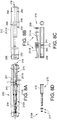
- shaft assembly 105 is similar to shaft assembly 5 of Figures 1-4 , 5A , 5B and 5D , except shaft assembly 105 includes bearing support for rotary distributor 127 in the form of a rolling element bearing 176.
- the rolling element bearing 176 is in the form of a tapered bearing set including a gear side bearing 177 and a roll side bearing 179.
- the bearings 177 and 179 include inner races 163 which are fixedly secured to the shaft 112 and outer races 165 that are fixedly secured to body 164 of the rotary distributor 127.
- the shaft 112 may include sleeves 159 for reduced wear and improved sealing to lip seals 155.
- O-rings 180 may be used to limit the leakage of lubricant 122.
- a gearbox side head lubricant path is used to send fresh lubricant 22A from the first input lubricant line 34 to the gearbox side head 8B to cool and lubricate gearbox side gear set 42 and to return used lubricant 22B to the outlet lubricant line 29.
- the path 82 starts at first input lubricant line 34 and progresses through gearbox side lubricant inlet port 68 on the rotary distributor 27.
- the path 82 continues through rotary distributor lubricant channels 83 to first radially extending hole 84 formed in shaft 12. From the first radially extending hole 84, the path 82 extends axially through first axially extending hole 85 formed in shaft 12 which is parallel and spaced from the longitudinal opening in the shaft 12. From the first axially extending hole 85 the path extends into cavity 51 formed in housing 46 of head 8B. When in the cavity 51, the path 82 extends to the gearbox side gear set 42 where the fresh lubricant 22A cools and lubricates the gear set 42.
- used lubricant 22B leaves the cavity along path 82 through second axially extending hole 86 formed in shaft 12 which is parallel and spaced from the longitudinal opening in the shaft 12. From the second axially extending hole 86, the path 82 extends radially through second radially extending hole 87 formed in shaft 12. From the second radially extending hole 87, the used lubricant 22B enters the rotary distributor 27 through rotary distributor lubricant channels 83. The used lubricant 22B then leaves along path 82 through the outlet port 70 to the outlet lubricant line 29.
- a roll side head lubricant path is used to send fresh lubricant 22A from the second input lubricant line 36 to the roll side head 9B to cool and lubricate roll side gear set 44 and to return used lubricant 22B to the outlet lubricant line 29.
- the path 88 starts at second input lubricant line 36 and progresses through roll side lubricant inlet port 69 on the rotary distributor 27. From the port 69 the path 88 continues through rotary distributor lubricant channels 83 to third radially extending hole 89 formed in shaft 12. From the third radially extending hole 89, the path 88 extends axially through third axially extending hole 90 formed in shaft 12 which is parallel and spaced from the longitudinal opening in the shaft 12.
- the path 88 extends radially inwardly through fourth radially extending hole 91 formed in shaft 12 to a cavity 92 formed by tube 35, plugs 93 and longitudinal opening 16 in shaft 12. From the cavity 92 the path 88 extends radially outwardly through fifth radially extending hole 94 formed in shaft 12. From the fifth radially extending hole 93A, the path 88 extends axially through fourth axially extending hole 94 formed in shaft 12 which is parallel and spaced from the longitudinal opening in the shaft 12 and then radially outwardly to sixth radially extending hole 96 formed in shaft 12. From the sixth radially extending hole 96 the path 88 extents into cavity 52 formed in housing 49 of head 9B. When in the cavity 52, the path 88 extends to the roll side gear set 44 where the fresh lubricant 22A cools and lubricates the gear set 44.
- used lubricant 22B leaves the cavity 51 along path 88 through the longitudinal opening in the shaft 12 to the cavity 51 formed in housing 46 of head 8B. From the cavity 51 the path 88 extends into second axially extending hole 86. From second axially extending hole 86, the path 88 extends radially through second radially extending hole 87 formed in shaft 12. From the second radially extending hole 87, the used lubricant 22B enters the rotary distributor 27 through rotary distributor lubricant channels 83.
- the used lubricant 22B may exit the cavity 51 along the longitudinal passageway 39A formed in tube 39 and through axial opening 39B in tube 39 and/or through passageway 37A between the tube 39 and the shaft 12. From the passageway 37A, the used lubricant 22B may pass through axial opening 39C in inner shaft liner 12A and through axial opening 12B in shaft, entering the rotary distributor 27 through rotary distributor lubricant channels 83.
- the used lubricant 22B then leaves along path 88 through the outlet port 70 to the outlet lubricant line 29.
- shaft assembly 205 is similar to shaft assembly 5 of Figures 1-7 , except shaft assembly 205 utilizes a first sleeve or hollow inner shirt 210 within longitudinal opening 216 of shaft 212 to serve as portions of the lubricant path 225. Shaft assembly 205 reduces the number of long internal passageways needed for the shaft assembly, compared to shaft assembly 5. Also, if the portions of the lubricant path 225 formed by the first sleeve is placed in a helical manner, the helical positioning may serve as a pump to assist the flow of lubricant in the path as the shaft rotates.
- the shaft assembly 205 is similar to shaft assembly 5 of Figures 1-7 .
- Shaft assembly 205 includes a shaft 212 similar to shaft 12 of Figures 1-7 , except shaft 212 does not have some of the axially extending internal passageways for shaft 12.
- the shaft 212 is supported on its first end 218 by gearbox side head 208B and on its second end 220 by roll side head 209B.
- the heads 208B and 209B are similar to heads 8B and 9B of the shaft assembly 5 of Figures 1-7 .
- the hollow inner shirt or sleeve 210 is fitted to longitudinal opening 216 in shaft 212.
- a second hollow inner shirt or second sleeve 210A may also be fitted to the internal longitudinal opening 216 in shaft 212.
- the shaft assembly 205 includes a rotary distributor 227 connected to the shaft 212 on its periphery 214.
- the rotary distributor 227 is similar to distributor 27 of Figures 1-7 .
- the rotary distributor 227 advances lubricant 222 to gearbox side gear set 242 and roll side gear set 244 along lubricant path 225.
- the gearbox side gear set 242 and roll side gear set 244 are similar to gearbox side gear set 42 and roll side gear set 44 of Figures 1-7 .
- the first sleeve 210 includes external grooves 211 extending both radially and axially. It should be appreciated that the grooves 211 may merely extend axially. By extending both radially and axially, the first sleeve 210 may be stronger and the combined radially and axial extending grooves 211 may serve as a pump to assist the flow of lubricant in the path as the shaft 212 rotates.
- the grooves 211 may be helically shaped or spirally shaped. As shown the grooves may include a helically shaped gearbox side groove 211A and a helically shaped roll side groove 211B. As shown the grooves 211A and 211B have the same orientation. It should be appreciated that the grooves may have opposed orientation to assist movement of the lubricant 222 in the grooves 211A and 211B.
- the first sleeve 210 may include a gearbox side inlet cylindrical circumferential groove 241 and a roll side inlet cylindrical circumferential groove 243 formed in the outer periphery of the first sleeve 210.
- the gearbox side inlet cylindrical circumferential groove 241 provides a lubricant passage between the gearbox side helically shaped groove 211A and gearbox side head lubricant line 234.
- the roll side inlet cylindrical circumferential groove 243 provides a lubricant passage between the roll side helically shaped groove 211B and roll side head lubricant line 236.
- the first sleeve 210 may further include a sleeve radial cross hole 213 through the first sleeve 210.
- the sleeve radial cross hole 213 provides a lubricant passage from the between the longitudinal opening 216 of the shaft 212 and outlet lubricant line 229.
- the shaft 205 may include a first radially extending hole 284 for passage of fresh lubricant 222A to the gearbox side head 208B.
- the shaft 205 may also include a second radially extending hole 286 for passage of fresh lubricant 222A to the roll side head 209B.
- the shaft 205 may also include a third radially extending hole 287 for passage of used lubricant 222B from the longitudinal opening 216 of the shaft 212.
- the first radially extending hole 284 may be in the form of first gearbox side passageway 284 for passage of fresh lubricant 222A from longitudinal opening 216 of shaft 212 to gearbox side heard cavity 251 in gearbox side head 208B. While a solitary gearbox side passageway may be sufficient, as shown in Figure 8B the shaft 205 includes a second gearbox side passageway 290 positioned opposed to the first gearbox side passageway 284.
- the second radially extending hole 286 may be in the form of a first roll side passageway 286 for passage of fresh lubricant 222A from longitudinal opening 216 of shaft 212 to roll side head cavity 252 in roll side head 209B. While a solitary roll side passageway may be sufficient, as shown in Figure 8B the shaft 205 includes a second roll side passageway 295 positioned opposed to the first roll side passageway 286.
- the passageway 284, 286, 290 and 295 may be radial or normal to the shaft centerline 7, or as shown be skewed axially outwardly to reduce the length of second sleeve 210A.
- the shaft 212 may further include a distribution gearbox side radial through hole 287A for passage of fresh lubricant 222A from the rotary distributor 227 to the first sleeve 210 and a distribution roll side radial through hole 287B for passage of fresh lubricant 222A from the rotary distributor 227 to the first sleeve 210.
- the second sleeve 210A includes a main body 215 and adapters 217. It should be appreciated that the invention may be practiced with the first sleeve 210 and the second sleeve 210A being integral with each other. The use of the separate first sleeve 210 and second sleeve 210A may provide for ease of manufacture and assembly.
- the second sleeve 210A may have helical groove(s) like the first sleeve 210
- the second sleeve 210A may (as shown in Figure 9 ) have an outer periphery 219 at least partially spaced from the shaft 212 to provide a lubricant passageway between the shaft and the outer periphery 219 of the second sleeve 210A.
- the first sleeve 210 may similarly use space between its outer periphery 210A and the shaft 210 as the lubricant passageway.
- the lubricant paths 225 are shown as arrows 225A, 225B, 225C and 225D, respective, for the gearbox side fresh lubricant path 225A, the gearbox side used lubricant path 225B, the roll side fresh lubricant path 225C, and the roll side used lubricant path 225D.
- fresh lubricant 222A flows from lubricant refreshing device 231 similar to device 31 of Figures 1-7 .
- the fresh lubricant 222A from the device 231 is preferably separated so that flow can be assured to both the gearbox side head 208B and the roll side head 209B.
- the fresh lubricant 222A exiting the device 231 enters gearbox side head lubricant line 234 and enters roll side head lubricant line 236.
- the gearbox side head lubricant line 234 may include gearbox side head line lubricant gauge or measuring device 238 and the roll side head lubricant line 236 may include roll side head line lubricant gauge or measuring device 240.
- the gauges 238 and 240 may be connected to monitoring systems (not shown) to monitor whether lubricant is flowing (using a flow measuring device) or has proper pressure (using a pressure gage).
- the flow of fresh lubricant 222A along gearbox side fresh lubricant path is shown by arrows 225A.
- the fresh lubricant 222A moves from the lubricant refreshing device 231 to gearbox side head lubricant line 234.
- the fresh lubricant 222A moves through gearbox side inlet port 268 on the rotary distributor 227 to internal channels 283 formed in the rotary distributor 227.
- fresh lubricant 222A moves through distribution gearbox side radial through hole in shaft 212 to gearbox side inlet cylindrical circumferential groove 241.
- fresh lubricant 222A moves through gearbox side helically shaped groove 211A to gearbox side outlet cylindrical circumferential groove 298 formed in the first sleeve 210.
- gearbox side outlet cylindrical circumferential groove 298 fresh lubricant 222A moves through the gearbox side passageways 284 and 290 to the gearbox side head cavity 251.
- Fresh lubricant in the cavity 251 cools, cleans and lubricates the gearbox side gear set 242.
- Used lubricant 222B moves through plug passageways 298A formed in gearbox side plug 299A to the longitudinal opening 216 internal to first sleeve 210. It should be appreciated that the plug 299A may be integral with the gear side head housing 246.
- used lubricant 222B passes through sleeve radial cross hole 213 to outlet cylindrical circumferential groove 241A formed in the first sleeve 210. From the outlet cylindrical circumferential groove 241A, the used lubricant 222B moves through third radially extending hole 287 in shaft 212 to internal channels 283 formed in the rotary distributor 227. It should be appreciated that if the sleeve radial cross hole 213 and the third radially extending hole 287 in shaft 212 are aligned, the outlet cylindrical circumferential groove 241A could be eliminated. From the internal channels 283, the used lubricant 222B moves through outlet port 270 to outlet lubricant line 229. From the outlet lubricant line 229, the used lubricant 222B returns to the lubricant refreshing device to complete its journey.
- the flow of fresh lubricant 222A along roll side fresh lubricant path is shown by arrows 225C.
- the fresh lubricant 222A moves from the lubricant refreshing device 231 to roll side head lubricant line 236.
- the fresh lubricant 222A moves through roll side inlet port 269 on the rotary distributor 227 to internal channels 283 formed in the rotary distributor 227.
- fresh lubricant 222A moves through distribution roll side radial through hole 287B in shaft 212 to roll side inlet cylindrical circumferential groove 243.
- fresh lubricant 222A moves through roll side helically shaped groove 211B to roll side outlet cylindrical circumferential groove 243 formed in the first sleeve 210. From the roll side outlet cylindrical circumferential groove 299, fresh lubricant 222A moves through second sleeve passageways 297A formed in second sleeve 210A.
- fresh lubricant 222A moves through to the roll side head cavity 252.
- Fresh lubricant in the cavity 252 cools, cleans and lubricates the roll side gear set 244.
- Used lubricant 222B moves through plug passageways 299B formed in roll side plug 299B to the longitudinal opening 216 internal to first sleeve 210. It should be appreciated that the plug 299B may be integral with the roll side head housing 249.
- used lubricant 222B passes through sleeve radial cross hole 213 to outlet cylindrical circumferential groove 241A formed in the first sleeve 210. From the outlet cylindrical circumferential groove 241A, the used lubricant 222B moves through third radially extending hole 287 in shaft 212 to internal channels 283 formed in the rotary distributor 227. From the internal channels 283, the used lubricant 222B moves through outlet port 270 to outlet lubricant line 229. From the outlet lubricant line 229, the used lubricant 222B returns to the lubricant refreshing device to complete its journey.
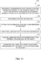
- method 300 for method for providing lubrication to a transmission shaft in a rolling mill machine includes step 302 of providing a transmission shaft having a central opening extending to the opposed ends of the shaft and internal passageways extending inwardly from the outer periphery of the shaft and step 304 of providing a rotary distributor.
- the method 300 further includes step 306 of fitting the distributor over the outer periphery of the shaft and step 308 of inputting lubricant into the rotary distributor.
- the method 300 also includes the step 310 of passing lubricant from the distributor to the internal passageways of the shaft and step 312 of advancing the lubricant from the internal passageways of the shaft to the opposed ends of the shaft.
- the method 300 may be provided such that the method further includes the step of inserting a sleeve into the central opening of the shaft.
- the method 300 may be provided such that the method further includes the step of providing a passageway between the sleeve and the body and wherein the step of advancing the lubricant from the internal passageways of the shaft to the opposed ends of the shaft includes advancing the lubricant along the passageway between the sleeve and the body.
- the method 300 may be provided such that the step of providing a passageway between the sleeve and the body includes providing a helical passageway between the sleeve and the body.
- the methods, systems, and apparatus described herein facilitate efficient and economical cooling and lubrication of a spindle. Exemplary embodiments of methods, systems, and apparatus are described and/or illustrated herein in detail. The methods, systems, and apparatus are not limited to the specific embodiments described herein, but rather, components of each apparatus and system, as well as steps of each method, may be utilized independently and separately from other components and steps described herein. Each component, and each method step, can also be used in combination with other components and/or method steps.
- the articles “a”, “an”, “the”, and “the” are intended to mean that there are one or more of the element(s)/component(s)/etc.
- the terms “comprising”, “including”, and “having” are intended to be inclusive and mean that there may be additional element(s)/component(s)/etc. other than the listed element(s)/component(s)/etc.
- Described herein are exemplary methods, systems and apparatus utilizing different coolant flow into and out of a spindle that reduces or eliminates the excessive maintenance costs and down time caused by the ineffective and expensive spindle lubrication methods. Furthermore, the exemplary methods system and apparatus achieve increased reliability while lowering investment and maintenance costs.
- the methods, system and apparatus described herein may be used in any suitable application. However, they are particularly suited for high temperature spindle application, such as rolling mills.
- spindle device and system Exemplary embodiments of the spindle device and system are described above in detail.
- the spindle and the associated systems and methods are not limited to the specific embodiments described herein, but rather, components of the systems may be utilized independently and separately from other components described herein.
- the components may also be used in combination with other motor systems, methods, and apparatuses, and are not limited to practice with only the systems and apparatus as described herein. Rather, the exemplary embodiments can be implemented and utilized in connection with many other applications.
Description
- The embodiments described herein relate generally to a rolling stand for use in a metal rolling mill, and more specifically, to a transmission shaft assembly and method associated with the shaft assembly.
- The rolling process consists of passing a hot steel billet through a "rolling mill", also called a "rolling train". The modern rolling train consists of multiple rolling stands arranged in an in-line configuration. Each rolling stand consists of a top and a bottom roll, driven through a gearbox by an electric motor. The rolls of the stands have contours or "grooves" machined into the rolls, so that the hot billet passing between the grooves is reduced in size and shaped by each subsequent stand. Typical motor sizes for modern mills is 600kW to 1200kW for each stand. Typically, 15 to 21 stands are used depending on the size of the feed billet and the finished product. Finishing speeds of 10-15 m/sec. are common today.
- The tension between each stand must be accurately controlled, as the slightest change in tension will affect the shape of the product. Additionally, as the billet head end enters each subsequent rolling stand, the speed drop must recover very fast, so as not affect the tension control.
- As the hot billet passes through the rolling train it is shaped, reduced in size, and lengthened by the mill stands. The product is then transferred to a walking beam cooling bed (typically 60-90 m long), via a high-speed transfer system (braking slide/aprons). Shears in the rolling train make head and tail crops, as well as divide the material to fit the cooling bed.
- As stated above, each rolling stand consists of a top and a bottom roll, driven through a gearbox by an electric motor. Typically, a double universal joint drive shaft transfers the rotational energy from the gearboxes to the top and bottom rolls. The drive shaft separates the gearbox and the electric motor from the intense heat of the billet passing between the rolls.
- Each of the rolls has rolling element bearings typically spherical roller bearings that need to be lubricated and that are subject to intense heat from the billet.
- Continuous oil-lubricated spindles offer users a reliable way to continuously remove damaging heat from spindles while in operation. Because the oil flows on a regular basis, the need to maintain grease levels and to clean up environmentally unfriendly grease are eliminated. The oil lubrication concept significantly extends the life of spindle operations and reduces mill downtime.
- Clean, temperature-regulated oil from the rolling mill's lubrication system (or from their own lubrication system) is introduced into the spindle from the driven end and transferred to the roll side. The oil is circulated through the roll-side geared elements and is transferred back from the roll side to an oil-collecting hood mounted at the driven side. The heated oil is then transferred back to the rolling mill's oil circulating system for cooling and cleaning.
- An oil-collecting hood that is mounted at the driven side usually generates a lot of maintenance problems, increasing downtimes and complicates the overall maintenance operation because it is such a big and complex box, as well as, increasing the final cost of the continuously oil lubricating gear spindle.
-
WO 2013/068148 A1 , forming the basis for the preamble of claim 1, discloses a rolling mill drive having an axially displaceable toothed articulated spindle extending between a toothed articulated element arranged between an interlocking chamber on the roller side and a toothed articulated element arranged in an interlocking chamber on the transmission side, wherein at least one of the interlocking chambers is filled with a lubricating medium, wherein the lubricating medium pretensions the toothed articulated spindle with an axial force directed towards the roller side. - The present invention provides a transmission shaft assembly as defined in claim 1. According to an embodiment of the present invention, a transmission shaft assembly for a rolling stand for use in a metal rolling mill is provided. The transmission shaft assembly transmits lubricant through the assembly. The transmission shaft assembly includes a shaft having an outer periphery and defining a centrally positioned longitudinal opening extending from a first end to an opposed second end of the shaft. The shaft defines a plurality of internal passageways in the shaft. The transmission shaft assembly also includes a rotary distributor mounted on the outer periphery of the shaft. The shaft assembly provides a conduit for the lubricant through the plurality of internal passageways in the shaft.
- According to another embodiment of the present invention, the transmission shaft assembly may be configured such that the rotary distributor includes first and second inputs for inputting lubricant into the distributor and an output for outputting lubricant from the distributor.
- According to yet another embodiment of the present invention, the transmission shaft assembly may be configured such that the rotary distributor includes first and second seals. The seals are axially spaced apart from each other and seal the rotary distributor to the outer periphery of said shaft.
- According to yet another embodiment of the present invention, the transmission shaft assembly may be configured such that the seals are lip seals.
- According to yet another embodiment of the present invention, the transmission shaft assembly may be configured such that the plurality of internal passageways includes a plurality of radially extending passageways and a plurality of axially extending passageways.
- According to yet another embodiment of the present invention, the transmission shaft assembly may be configured such that the plurality of internal passageways includes at least one passageway that extends simultaneously radially and axially.
- According to yet another embodiment of the present invention, the transmission shaft assembly may be configured such that the shaft includes a body portion defining an inner periphery of the body portion and a sleeve including an outer periphery of the sleeve fitted to the inner periphery of the body portion.
- According to yet another embodiment of the present invention, the transmission shaft assembly may be configured such that the inner periphery of the body portion and the outer periphery of the sleeve defining a passageway between each other.
- According to yet another embodiment of the present invention, the transmission shaft assembly may be configured such that the passageway between the inner periphery of the body portion and the outer periphery of the sleeve is an axially extending passageway.
- According to yet another embodiment of the present invention, the transmission shaft assembly may be configured such that at least a portion of the passageway between the inner periphery of the body portion and the outer periphery of the sleeve is a helical passageway.
- According to yet another embodiment of the present invention, a transmission shaft for a rolling stand for use in a metal rolling mill is provided. The transmission shaft includes a body having a generally cylindrical outer periphery and defining a centrally positioned longitudinal opening extending from a first end to an opposed second end of the shaft. The body further defines a plurality of internal passageways in the body.
- According to yet another embodiment of the present invention, the transmission shaft may be configured such that the plurality of internal passageways includes a plurality of radially extending passageways and a plurality of axially extending passageways.
- According to yet another embodiment of the present invention, the transmission shaft may be configured such that the body defines an inner periphery of the body. The shaft may also include a sleeve having an outer periphery of the sleeve fitted to the inner periphery of the body.
- According to yet another embodiment of the present invention, the transmission shaft may be configured such that the body and the sleeve define a passageway between the body and the sleeve.
- According to yet another embodiment of the present invention, the transmission shaft may be configured such that the passageway between the inner periphery of the body portion and the outer periphery of the sleeve is an axially extending passageway.
- According to yet another embodiment of the present invention, the transmission shaft may be configured such that at least a portion of the passageway between the inner periphery of the body portion and the outer periphery of the sleeve is a helical passageway.
- According to yet another embodiment of the present disclosure, a method for providing lubrication to a transmission shaft in a rolling mill machine is provided. The method includes the steps of providing a transmission shaft having a central opening extending to the opposed ends of the shaft and internal passageways extending inwardly from the outer periphery of the shaft; providing a rotary distributor, fitting the distributor over the outer periphery of the shaft, inputting lubricant into the rotary distributor, passing lubricant from the distributor to the internal passageways of the shaft, and advancing the lubricant from the internal passageways of the shaft to the opposed ends of the shaft.
- According to yet another embodiment of the present disclosure, the method may be provided such that the method further includes the step of inserting a sleeve into the central opening of the shaft.
- According to yet another embodiment of the present disclosure, the method may be provided such that the method further includes the step of providing a passageway between the sleeve and the body and wherein the step of advancing the lubricant from the internal passageways of the shaft to the opposed ends of the shaft includes advancing the lubricant along the passageway between the sleeve and the body.
- According to yet another embodiment of the present disclosure, the method may be provided such that the step of providing a passageway between the sleeve and the body includes providing a helical passageway between the sleeve and the body.
-
-
Figure 1 is a perspective view of rolling stand for use in a metal rolling mill that may incorporate a transmission shaft assembly according to the present invention; -
Figure 2 is a perspective view, partially in cross section, of an embodiment of the present invention showing a transmission shaft assembly according to the present invention; -
Figure 3 is a partial perspective view, partially in cross section, of the transmission shaft assembly ofFigure 2 , showing lip seals on the shaft in greater detail; -
Figure 4 is a partial perspective view of the transmission shaft assembly ofFigure 2 , showing a collar used to inject and withdraw oil into the shaft assembly; -
Figure 5A is a plan view of a hydraulic distributor assembled onto the transmission shaft assembly ofFigure 2 ; -
Figure 5B is a partial plan view, partially in cross section, of the distributor ofFigure 5A ; -
Figure 5C is a partial plan view, partially in cross section, of an alternate distributor utilizing roller bearings; -
Figure 5D is a partial plan view, partially in cross section, of the distributor ofFigure 5A ; -
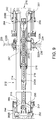
Figure 6 is a perspective view, partially in cross section, of the transmission shaft of the transmission shaft assembly ofFigure 2 , showing axial extending oil passageways; -
Figure 7 is a cross sectional view the transmission shaft assembly ofFigure 2 , showing the oil paths along the axial extending oil passageways; -
Figure 8A is a cross sectional view of another embodiment of the present invention in the form of transmission shaft assembly having sleeves with helical oil passageways formed in the outer periphery of the sleeves; -
Figure 8B is a cross sectional view of the transmission shaft of the transmission shaft assembly ofFigure 8A , showing the radial holes for connecting to the oil passageways; -
Figure 8C includes plan, end and cross sectional views of a first sleeve used in the transmission shaft assembly ofFigure 8A ; -
Figure 8D is an exploded cross sectional view of a second sleeve and other sleeves used in the transmission shaft assembly ofFigure 8A ; -
Figure 9 is a cross section view of the transmission shaft assembly ofFigure 8A ; -
Figure 10 is a cross section view of the transmission shaft assembly ofFigure 8A showing the oil paths along the spirally extending oil passageways; and -
Figure 11 is a flow chart of a method of using a transmission shaft assembly according to another embodiment of the present invention. - Hot, semi-molten-molten steel may be made into very long shapes with uniform thicknesses by use of a rolling mill or rolling process. The rolling process consists of passing a hot steel billet through a "rolling mill", also called a "rolling train". The modern rolling train consists of multiple rolling stands arranged in an in-line configuration.
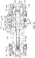
- Referring now to
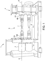
Figure 1 , one such rolling stand 1 consists of an upper 2 and alower roll 3, driven through agearbox 4 by a power source, for example, an electric motor. Therolls - The
upper roll 2 and thelower roll 3 are positioned at a substantial distance from thegearbox 4 which is used to increase the torque and reduce the speed of the power source. Thegearbox 4 is positioned at a substantial distance from the hot billet, so that the gearbox is not harmed by the elevated temperatures of the billet. - Rotating connecting
members gearbox 4 to theupper roll 2 and thelower roll 3, respectively. The rotating connectingmembers spindles - The
spindles - According to an exemplary embodiment of the present invention and referring now to
Figures 1-7D , a spindle ortransmission shaft assembly 5 for a rolling stand 1 for use in a metal rolling mill is provided. Note that theupper spindle 5 transmits rotational energy from thegearbox 4 toupper roll 2. It should be appreciated that the rolling stand 1 may include other spindles, for example,lower spindle 6 adapted to transmit rotational energy from thegearbox 4 tolower roll 3. Thelower spindle 6 may be similar or identical to theupper spindle 5. It should be appreciated that the rolling mill may include many spindles, each similar or identical to thespindles - As shown in
Figures 1 and2 , the spindle ortransmission shaft assembly 5 has a transmission shaftrotational centerline 7. Thegearbox 4 has a gearbox output member, for example and as shown, agearbox output shaft 4A that transmits to torque from thegearbox 4 to thespindle 5. Theupper roll 2 has an upper roll input member, for example and as shown, an upperroll input shaft 2A that transmits torque from thespindle 5 to theupper roll 2. Thegearbox output shaft 4A rotates about gearboxoutput shaft centerline 8. Similarly, the upperroll input shaft 4A rotates about upper rollinput shaft centerline 9. - To provide smooth transfer of rotational energy from the
gearbox 4 to theupper roll 2, the transmission shaftrotational centerline 7. the gearboxoutput shaft centerline 8, the upper rollinput shaft centerline 9 and the transmission shaftrotational centerline 7 are, preferably, coincident. It is extremely difficult to mount thegearbox 4 and theroll 2 in such a position that the gearboxoutput shaft centerline 8 and the upper rollinput shaft centerline 9 are coincident. - To accommodate the lack of coincidence or collinearity of the
centerlines shaft assembly 5 to thegearbox 4 and a roll side head or joint 9B to connect theshaft assembly 5 to theroll 2. - The
gearbox side head 8B and theroll side head 9B may, as shown, be articulating heads so that the gearboxoutput shaft centerline 8, the upper rollinput shaft centerline 9 and the transmission shaftrotational centerline 7 may be at angles to each other and still provide for smooth transfer of rotational energy from thegearbox 4 to theroll 2. - As shown in
Figure 2 , thetransmission shaft assembly 5 includes ashaft 12. Theshaft 12 has anouter periphery 14. Theshaft 12, as shown, preferably defines a centrally positionedlongitudinal opening 16 extending from afirst end 18 to an opposedsecond end 20 of theshaft 12. - As shown in
Figure 2 , thetransmission shaft assembly 5, transmitslubricant 22 through theassembly 5. Thelubricant 22 serves to cool the shaft assemblies and to providelubricant 22 to the articulatingjoints - The
lubricant 22 may be transmitted through theassembly 5 by alubrication system 24. Thelubrication system 24 cycles thelubricant 22 along a lubricant path 25. - Referring to
Figures 6 and7 , theshaft 12 defines a plurality of internal passageways 26 in theshaft 12. Thelubricant 22 flows along the lubricant path 25 in the internal passageways 26 of the shaft. - Referring again to
Figures 2 ,5A and6 , thetransmission shaft assembly 5 also includes arotary distributor 27 mounted on theouter periphery 14 of theshaft 12. As shown inFigure 2 , therotatory distributor 27 receives thelubricant 22 from theinput lubricant line 28 and advances it toward the internal passageways 26 and receives thelubricant 22 from the internal passageways 26 and advances it toward theoutlet lubricant line 29. Theshaft assembly 5 provides aconduit 30 for thelubricant 22 through the plurality of internal passageways 26 in theshaft 12. - The
lubrication system 24 may, as shown inFigure 2 , further include a lubricantrefreshing device 31 which may clean and cool thelubricant 22 for reuse in thetransmission shaft assembly 5. The lubricantrefreshing device 31 may be any device that can cool and clean or filter thelubricant 22.Used lubricant 22 from theshaft 12 is transported through theoutlet lubricant line 29 to thelubricant refreshing device 31. Thelubrication system 24 may further include apump 32 for urging thelubricant 22 along the lubricant path 25. Thepump 32 may be internal or external to thelubricant refreshing device 31. - As shown in
Figures 2 and5A , to assure that fresh lubricant flows to both thefirst end 18 and thesecond end 20 of theshaft 12, theinput lubricant line 27 may be in the form of, or split into, a firstinput lubricant line 34 for providing lubricant to thefirst end 18 of theshaft 12 and a secondinput lubricant line 36 for providing lubricant to thesecond end 20 of theshaft 12. The firstinput lubricant line 34 and the secondinput lubricant line 36 may utilize a common pump or may each have their own pump (not shown). The firstinput lubricant line 34 may have agauge 38 in theline 34 to measure flow or pressure in theline 34 to monitor the flow oflubricant 22 going to thefirst end 18 of theshaft 12. - Similarly, the second
input lubricant line 36 may have agauge 40 in the line to measure flow or pressure in theline 36 to monitor the flow oflubricant 22 going to thesecond end 20 of the shaft. Thegauges lines gauges 38 & 40. - The
lubrication system 24 for lubricating theshaft assembly 6 provideslubricant 22 to the support surfaces 23 and torque transmitting surfaces 21 of theshaft assembly 5. - For example and as shown in
Figure 2 , since the shaft assembly is in an application where product changes may necessitate production set up and tooling changes and since the shaft assembly is in an environment with elevated temperatures, theshaft assembly 5 may need to be changed quickly and easily. Theheads example flats 35 that engage matching features in theshafts heads shaft rotation centerline 7.Springs 37 may be positioned in thelongitudinal opening 16 of theshaft 12 to urge theheads heads shafts heads springs 37 to permit theheads shafts shaft assembly 5 may then be removed radially from theshafts central tube 39 may be positioned inside thesprings 37 to accommodate the movement oflubricant 22. - For example and as shown in
Figure 2 , torque is transferred from thegearbox side head 8B to theshaft 12 by a firsttorque transfer arrangement 42, from theshaft 12 to a firsttorque transfer arrangement 42 and then from theroll side head 9B to theshaft 12 by a secondtorque transfer arrangement 44. As shown inFigure 2 , the firsttorque transfer arrangement 42 may be in the form of a couple or coupling set that include anouter coupling member 45 fixed tohousing 46 ofgearbox side head 8B and aninner coupling member 47 fixed to theouter periphery 14 ofshaft 12. - It should be appreciated, that the coupling set 42 may be the form of a gear set, with the
outer coupling member 45 in the form of an outer gear fixed to housing orsleeve 46 ofgearbox side head 8B and aninner coupling member 47 in the form of an inner gear fixed to theouter periphery 14 of shaft. - Since the gearbox
output shaft centerline 8 about whichouter gear 45 rotates may be skewed from the transmission shaftrotational centerline 7 about whichinner gear 47 rotates, thegears gears first end 18 of theshaft 12. - Similarly, the second
torque transfer arrangement 44 may be in the form of a coupling set or gear set that include anouter gear 48 fixed to housing orsleeve 49 ofroll side head 9B and aninner gear 50 fixed to theouter periphery 14 ofshaft 12. Thegears gears second end 18 of theshaft 12. - As stated earlier the
lubricant 22 is used to lubricate the matching engaging faces of the teeth of the gear sets 42 and 44. To keeplubricant 22 on the faces of the teeth of the gear sets 42 and 44, the lubricant is contained in afirst cavity 51 formed by thefirst end 18 andperiphery 14 of theshaft 12 and thehousing 46 ofgearbox side head 8B and in asecond cavity 52 formed between thesecond end 20 andperiphery 14 of theshaft 12 and housing 53 ofroll side head 9B. - Since the gearbox
output shaft centerline 8 about whichhousing 46 ofgearbox side head 8B rotates may be skewed from the transmission shaftrotational centerline 7 and from the rollinput shaft centerline 9 about whichhousing 49 ofroll side head 9B rotates, thegearbox side head 8B and theroll side head 9B may have a gearbox side head seal 53 and a rollside head seal 54, respectively, to contain thelubricant 22 in thefirst cavity 51 and in thesecond cavity 52, respectively. - The gearbox side head seal 53 and the roll
side head seal 54 mate withouter periphery 14 ofshaft 14 to seal thelubricant 22 within thefirst cavity 51 and in thesecond cavity 52, respectively. Theseals 53 and 54 may be any seal capable of containing thelubricant 22. For example, the seals may be configured to accommodate a misalignment of theheads shaft 14. Theseals 53 and 54 may be permitted to float or move radially as the heads misalign with the shaft so that theseals 53 and 54 remain in uniform contact with theouter periphery 14 of theshaft 14 around the circumference of theshaft 14. - Referring now to
Figure 3 , the gearbox side head seal 53 is shown in greater detail within thegearbox side head 8B. The gearbox side head seal 53 may include aninner seal 55 and anouter seal 56. Theseals lip seal portion 57 and aseal body 58. Thelip seal portion 57 engages theperiphery 14 of theshaft 12. As shown, theshaft 12 may include an outercylindrical sleeve 59. The outercylindrical sleeve 59 may be made of a material more suitable for engagement with the seal 53 and may be replaced when wear necessitates its replacement. - The
seal body 58 of theseals pockets 60 formed in thehousing 46 of thegearbox side head 8B to permit the seals to axially float in the housing, permitting thelip seal portion 56 to better conform toperiphery 14 ofshaft 12 if thehousing 46 and theshaft 12 are not perfectly concentric. O-rings 62 may be positioned in thepockets 60 to prevent lubricant leakage as theseals pockets 60 of thehousing 46. Referring now toFigures 4 ,5A ,5C and5D , therotary distributor 27 is shown in greater detail. Therotary distributor 27 serves to permitlubricant 22 to enter and exit theshaft 12 while theshaft 12 is rotation. The rotary distributor may have any configuration that accomplishes the entering and exiting of lubricant through the rotatingshaft 12. For example and as shown inFigures 4 and5A-D , therotary distributor 27 may include abody 64 which is stationary, as theshaft 12 rotates. Thebody 64 may be rotationally fixed to ananchor 66 by, for example a protrusion in the form of apin 67 extending radially outwardly from thebody 64. Thepin 67 may be cylindrical and permit radial motion of the pin to theanchor 66 to accommodate any runout that may occur in theshaft 12 as it rotates - Referring now to
Figures 4 and5A , to permit separate lubricant flow to thegearbox side head 8B and theroll side head 9B, thebody 64 of therotary distributor 27 may include a gearbox sidelubricant inlet port 68 and a roll sidelubricant inlet port 69. The gearbox sidelubricant inlet port 68 is connected to the firstinput lubricant line 34 and the roll sidelubricant inlet port 69 is connected to the secondinput lubricant line 36. - To receive the used lubricant flow, the
body 64 of therotary distributor 27 may include anoutlet port 70. Theoutlet inlet port 70 is connected to theoutlet lubricant line 29. - While the
anchor 66 andpin 67 prevents rotation of thebody 64 of therotary distributor 27, preventing axial movement of thebody 64 alongshaft 12 is also desired. As shown inFigures 4 ,5B and5D , therotary distributor 27 may further include an axial movement limiting device in the form of a gearboxside shoulder ring 72 and a rollside shoulder ring 74. Therings shaft 12 and limit axial motion of thebody 64 of therotary distributor 27. - As shown in
Figures 5B and5D , to prevent excessive axial load on therotary distributor 27, one of the gearboxside shoulder ring 72 and the rollside shoulder ring 74 is axial fixed and the other axially floats. As shown in 5B and 5D, the gearboxside shoulder ring 72 floats and the rollside shoulder ring 74 is fixed. The floating of the gearboxside shoulder ring 72 is permitted using alocking ring 75 which is fixedly secured to theshaft 12. The lockingring 75 permits a limited amount of axial float to the gearboxside shoulder ring 72. Ashim 75A may be positioned between the lockingring 75 and the gearboxside shoulder ring 72 to accurately set and or adjust the axial float. - To control the rotation of the shaft within the
rotary distributor 27, a bearing support is desired to support therotary distributor 27 on the shaft. The bearing support, as shown inFigures 5B and5D , may be provided by a sleeve bearing in the form ofbronze bushing 76. Note that other materials, including other metals, polymers and composites or any others used for sleeve bearing may likewise be used. - The
bushing 76 may as shown be fixedly secured to thebody 64 of therotary distributor 27. Thebushing 76 may include radially extendingside walls 77 which may provide bearing surfaces for the shoulder rings 72 and 74. Thebushing 76 may include grooves 78 for receiving seals in the form of, for example, O-rings 80 to contain thelubricant 22. - The
bushing 76 may be lubricated withlubricant 22 coming from the firstinput lubricant line 34 or from the secondinput lubricant line 36. Alternatively, thebushing 76 may be lubricated withlubricant 22 coming from a third input lubricant line (not shown). Thebody 64 of therotary distributor 27 may define abody cavity 65 that containslubricant 22 for use to lubricatebushing 76. Thebody cavity 65 is in fluid communication with either the firstinput lubricant line 34 or the secondinput lubricant line 36 through the respective one of the gearbox sidelubricant inlet port 68 or the roll sidelubricant inlet port 69. - Referring now to
Figure 5C , another embodiment of the present invention is shown asshaft assembly 105.Shaft assembly 105 is similar toshaft assembly 5 ofFigures 1-4 ,5A ,5B and 5D , exceptshaft assembly 105 includes bearing support forrotary distributor 127 in the form of a rolling element bearing 176. As shown the rolling element bearing 176 is in the form of a tapered bearing set including agear side bearing 177 and aroll side bearing 179. Thebearings inner races 163 which are fixedly secured to theshaft 112 andouter races 165 that are fixedly secured tobody 164 of therotary distributor 127. Theshaft 112 may includesleeves 159 for reduced wear and improved sealing to lip seals 155. O-rings 180 may be used to limit the leakage oflubricant 122. - Referring now to
Figures 6 and7 , the lubricant paths including the portion along their internal passageway formed in theshaft 12 are shown in greater detail. - As shown in
Figure 6 and7 , a gearbox side head lubricant path, shown as arrows 82, is used to send fresh lubricant 22A from the firstinput lubricant line 34 to thegearbox side head 8B to cool and lubricate gearbox side gear set 42 and to return used lubricant 22B to theoutlet lubricant line 29. The path 82 starts at firstinput lubricant line 34 and progresses through gearbox sidelubricant inlet port 68 on therotary distributor 27. - From the
port 68 the path 82 continues through rotarydistributor lubricant channels 83 to first radially extendinghole 84 formed inshaft 12. From the first radially extendinghole 84, the path 82 extends axially through first axially extendinghole 85 formed inshaft 12 which is parallel and spaced from the longitudinal opening in theshaft 12. From the first axially extendinghole 85 the path extends intocavity 51 formed inhousing 46 ofhead 8B. When in thecavity 51, the path 82 extends to the gearbox side gear set 42 where the fresh lubricant 22A cools and lubricates the gear set 42. - From the
cavity 51, used lubricant 22B leaves the cavity along path 82 through second axially extending hole 86 formed inshaft 12 which is parallel and spaced from the longitudinal opening in theshaft 12. From the second axially extending hole 86, the path 82 extends radially through second radially extendinghole 87 formed inshaft 12. From the second radially extendinghole 87, the used lubricant 22B enters therotary distributor 27 through rotarydistributor lubricant channels 83. The used lubricant 22B then leaves along path 82 through theoutlet port 70 to theoutlet lubricant line 29. - As shown in
Figure 6 and7 , a roll side head lubricant path, shown as arrows 88, is used to send fresh lubricant 22A from the secondinput lubricant line 36 to theroll side head 9B to cool and lubricate roll side gear set 44 and to return used lubricant 22B to theoutlet lubricant line 29. The path 88 starts at secondinput lubricant line 36 and progresses through roll sidelubricant inlet port 69 on therotary distributor 27. From theport 69 the path 88 continues through rotarydistributor lubricant channels 83 to third radially extendinghole 89 formed inshaft 12. From the third radially extendinghole 89, the path 88 extends axially through third axially extendinghole 90 formed inshaft 12 which is parallel and spaced from the longitudinal opening in theshaft 12. - From the third axially extending
hole 90, the path 88 extends radially inwardly through fourth radially extendinghole 91 formed inshaft 12 to a cavity 92 formed bytube 35, plugs 93 andlongitudinal opening 16 inshaft 12. From the cavity 92 the path 88 extends radially outwardly through fifth radially extending hole 94 formed inshaft 12. From the fifth radially extendinghole 93A, the path 88 extends axially through fourth axially extending hole 94 formed inshaft 12 which is parallel and spaced from the longitudinal opening in theshaft 12 and then radially outwardly to sixth radially extendinghole 96 formed inshaft 12. From the sixth radially extendinghole 96 the path 88 extents intocavity 52 formed inhousing 49 ofhead 9B. When in thecavity 52, the path 88 extends to the roll side gear set 44 where the fresh lubricant 22A cools and lubricates the gear set 44. - From the
cavity 52, used lubricant 22B leaves thecavity 51 along path 88 through the longitudinal opening in theshaft 12 to thecavity 51 formed inhousing 46 ofhead 8B. From thecavity 51 the path 88 extends into second axially extending hole 86. From second axially extending hole 86, the path 88 extends radially through second radially extendinghole 87 formed inshaft 12. From the second radially extendinghole 87, the used lubricant 22B enters therotary distributor 27 through rotarydistributor lubricant channels 83. - Alternatively and referring to
Figure 5D ,6 and7 , the used lubricant 22B may exit thecavity 51 along the longitudinal passageway 39A formed intube 39 and throughaxial opening 39B intube 39 and/or throughpassageway 37A between thetube 39 and theshaft 12. From thepassageway 37A, the used lubricant 22B may pass throughaxial opening 39C ininner shaft liner 12A and throughaxial opening 12B in shaft, entering therotary distributor 27 through rotarydistributor lubricant channels 83. - The used lubricant 22B then leaves along path 88 through the
outlet port 70 to theoutlet lubricant line 29. - Referring to
Figures 8A-D ,9 and 10 , another embodiment of the present invention is shown as shaft assembly 205. The shaft assembly 205 is similar toshaft assembly 5 ofFigures 1-7 , except shaft assembly 205 utilizes a first sleeve or hollowinner shirt 210 withinlongitudinal opening 216 ofshaft 212 to serve as portions of the lubricant path 225. Shaft assembly 205 reduces the number of long internal passageways needed for the shaft assembly, compared toshaft assembly 5. Also, if the portions of the lubricant path 225 formed by the first sleeve is placed in a helical manner, the helical positioning may serve as a pump to assist the flow of lubricant in the path as the shaft rotates. - Referring to
Figure 9 , the shaft assembly 205 is similar toshaft assembly 5 ofFigures 1-7 . Shaft assembly 205 includes ashaft 212 similar toshaft 12 ofFigures 1-7 , exceptshaft 212 does not have some of the axially extending internal passageways forshaft 12. Theshaft 212 is supported on its first end 218 bygearbox side head 208B and on its second end 220 byroll side head 209B. Theheads heads shaft assembly 5 ofFigures 1-7 . The hollow inner shirt orsleeve 210 is fitted tolongitudinal opening 216 inshaft 212. A second hollow inner shirt orsecond sleeve 210A may also be fitted to the internallongitudinal opening 216 inshaft 212. - The shaft assembly 205 includes a
rotary distributor 227 connected to theshaft 212 on itsperiphery 214. Therotary distributor 227 is similar todistributor 27 ofFigures 1-7 . Therotary distributor 227 advances lubricant 222 to gearbox side gear set 242 and roll side gear set 244 along lubricant path 225. The gearbox side gear set 242 and roll side gear set 244 are similar to gearbox side gear set 42 and roll side gear set 44 ofFigures 1-7 . - Referring now to
Figure 8A , thefirst sleeve 210 includesexternal grooves 211 extending both radially and axially. It should be appreciated that thegrooves 211 may merely extend axially. By extending both radially and axially, thefirst sleeve 210 may be stronger and the combined radially and axial extendinggrooves 211 may serve as a pump to assist the flow of lubricant in the path as theshaft 212 rotates. Thegrooves 211, as shown, may be helically shaped or spirally shaped. As shown the grooves may include a helically shapedgearbox side groove 211A and a helically shapedroll side groove 211B. As shown thegrooves grooves - As shown in
Figures 8D and9 , thefirst sleeve 210 may include a gearbox side inlet cylindricalcircumferential groove 241 and a roll side inlet cylindricalcircumferential groove 243 formed in the outer periphery of thefirst sleeve 210. The gearbox side inlet cylindricalcircumferential groove 241 provides a lubricant passage between the gearbox side helically shapedgroove 211A and gearbox sidehead lubricant line 234. Similarly, the roll side inlet cylindricalcircumferential groove 243 provides a lubricant passage between the roll side helically shapedgroove 211B and roll sidehead lubricant line 236. Thefirst sleeve 210 may further include a sleeveradial cross hole 213 through thefirst sleeve 210. The sleeveradial cross hole 213 provides a lubricant passage from the between thelongitudinal opening 216 of theshaft 212 andoutlet lubricant line 229. - Referring to
Figure 8B , the shaft 205 may include a first radially extendinghole 284 for passage offresh lubricant 222A to thegearbox side head 208B. The shaft 205 may also include a secondradially extending hole 286 for passage offresh lubricant 222A to theroll side head 209B. The shaft 205 may also include a thirdradially extending hole 287 for passage of usedlubricant 222B from thelongitudinal opening 216 of theshaft 212. The first radially extendinghole 284 may be in the form of firstgearbox side passageway 284 for passage offresh lubricant 222A fromlongitudinal opening 216 ofshaft 212 to gearbox side heardcavity 251 ingearbox side head 208B. While a solitary gearbox side passageway may be sufficient, as shown inFigure 8B the shaft 205 includes a secondgearbox side passageway 290 positioned opposed to the firstgearbox side passageway 284. - The second radially extending
hole 286 may be in the form of a firstroll side passageway 286 for passage offresh lubricant 222A fromlongitudinal opening 216 ofshaft 212 to rollside head cavity 252 inroll side head 209B. While a solitary roll side passageway may be sufficient, as shown inFigure 8B the shaft 205 includes a secondroll side passageway 295 positioned opposed to the firstroll side passageway 286. Thepassageway shaft centerline 7, or as shown be skewed axially outwardly to reduce the length ofsecond sleeve 210A. - The
shaft 212 may further include a distribution gearbox side radial throughhole 287A for passage offresh lubricant 222A from therotary distributor 227 to thefirst sleeve 210 and a distribution roll side radial throughhole 287B for passage offresh lubricant 222A from therotary distributor 227 to thefirst sleeve 210. - Referring to
Figure 8C , thesecond sleeve 210A is shown in greater detail. Thesecond sleeve 210A includes amain body 215 andadapters 217. It should be appreciated that the invention may be practiced with thefirst sleeve 210 and thesecond sleeve 210A being integral with each other. The use of the separatefirst sleeve 210 andsecond sleeve 210A may provide for ease of manufacture and assembly. While thesecond sleeve 210A may have helical groove(s) like thefirst sleeve 210, thesecond sleeve 210A may (as shown inFigure 9 ) have anouter periphery 219 at least partially spaced from theshaft 212 to provide a lubricant passageway between the shaft and theouter periphery 219 of thesecond sleeve 210A. It should be appreciated that thefirst sleeve 210 may similarly use space between itsouter periphery 210A and theshaft 210 as the lubricant passageway. - Referring now to
Figures 9 and10 , the lubricant paths 225 are shown asarrows fresh lubricant path 225A, the gearbox side usedlubricant path 225B, the roll sidefresh lubricant path 225C, and the roll side usedlubricant path 225D. As shown inFigure 9 andFigure 10 ,fresh lubricant 222A flows from lubricantrefreshing device 231 similar todevice 31 ofFigures 1-7 . Thefresh lubricant 222A from thedevice 231 is preferably separated so that flow can be assured to both thegearbox side head 208B and theroll side head 209B. Thefresh lubricant 222A exiting thedevice 231 enters gearbox sidehead lubricant line 234 and enters roll sidehead lubricant line 236. The gearbox sidehead lubricant line 234 may include gearbox side head line lubricant gauge ormeasuring device 238 and the roll sidehead lubricant line 236 may include roll side head line lubricant gauge ormeasuring device 240. Thegauges - Referring again to
Figure 10 , the flow offresh lubricant 222A along gearbox side fresh lubricant path is shown byarrows 225A. Thefresh lubricant 222A moves from the lubricantrefreshing device 231 to gearbox sidehead lubricant line 234. From the gearbox sidehead lubricant line 234, thefresh lubricant 222A moves through gearboxside inlet port 268 on therotary distributor 227 tointernal channels 283 formed in therotary distributor 227. From theinternal channels 283 in therotary distributor 227,fresh lubricant 222A moves through distribution gearbox side radial through hole inshaft 212 to gearbox side inlet cylindricalcircumferential groove 241. - From gearbox side inlet cylindrical
circumferential groove 241,fresh lubricant 222A moves through gearbox side helically shapedgroove 211A to gearbox side outlet cylindricalcircumferential groove 298 formed in thefirst sleeve 210. From the gearbox side outlet cylindricalcircumferential groove 298,fresh lubricant 222A moves through thegearbox side passageways side head cavity 251. Fresh lubricant in thecavity 251 cools, cleans and lubricates the gearbox side gear set 242. - Referring again to
Figure 10 , the flow of usedlubricant 222B along gearbox side used lubricant path is shown byarrows 225B.Used lubricant 222B moves throughplug passageways 298A formed in gearbox side plug 299A to thelongitudinal opening 216 internal tofirst sleeve 210. It should be appreciated that theplug 299A may be integral with the gearside head housing 246. - From the
longitudinal opening 216, usedlubricant 222B passes through sleeveradial cross hole 213 to outlet cylindricalcircumferential groove 241A formed in thefirst sleeve 210. From the outlet cylindricalcircumferential groove 241A, the usedlubricant 222B moves through third radially extendinghole 287 inshaft 212 tointernal channels 283 formed in therotary distributor 227. It should be appreciated that if the sleeveradial cross hole 213 and the third radially extendinghole 287 inshaft 212 are aligned, the outlet cylindricalcircumferential groove 241A could be eliminated. From theinternal channels 283, the usedlubricant 222B moves throughoutlet port 270 tooutlet lubricant line 229. From theoutlet lubricant line 229, the usedlubricant 222B returns to the lubricant refreshing device to complete its journey. - Referring again to
Figure 10 , the flow offresh lubricant 222A along roll side fresh lubricant path is shown byarrows 225C. Thefresh lubricant 222A moves from the lubricantrefreshing device 231 to roll sidehead lubricant line 236. From the gearbox sidehead lubricant line 236, thefresh lubricant 222A moves through rollside inlet port 269 on therotary distributor 227 tointernal channels 283 formed in therotary distributor 227. From theinternal channels 283 in therotary distributor 227,fresh lubricant 222A moves through distribution roll side radial throughhole 287B inshaft 212 to roll side inlet cylindricalcircumferential groove 243. - From roll side inlet cylindrical
circumferential groove 243,fresh lubricant 222A moves through roll side helically shapedgroove 211B to roll side outlet cylindricalcircumferential groove 243 formed in thefirst sleeve 210. From the roll side outlet cylindricalcircumferential groove 299,fresh lubricant 222A moves throughsecond sleeve passageways 297A formed insecond sleeve 210A. - From the
second sleeve passageways 297A,fresh lubricant 222A moves throughcylindrical passageway 295A formed between thesecond sleeve 210A andshaft 212 to rollside passageways cylindrical passageway 295A.passageways 297A formed insecond sleeve 210A. - From the
roll side passageways fresh lubricant 222A moves through to the rollside head cavity 252. Fresh lubricant in thecavity 252 cools, cleans and lubricates the roll side gear set 244. - Referring again to
Figure 10 , the flow of usedlubricant 222B along roll side used lubricant path is shown byarrows 225D.Used lubricant 222B moves throughplug passageways 299B formed in roll side plug 299B to thelongitudinal opening 216 internal tofirst sleeve 210. It should be appreciated that theplug 299B may be integral with the rollside head housing 249. - From the
longitudinal opening 216, usedlubricant 222B passes through sleeveradial cross hole 213 to outlet cylindricalcircumferential groove 241A formed in thefirst sleeve 210. From the outlet cylindricalcircumferential groove 241A, the usedlubricant 222B moves through third radially extendinghole 287 inshaft 212 tointernal channels 283 formed in therotary distributor 227. From theinternal channels 283, the usedlubricant 222B moves throughoutlet port 270 tooutlet lubricant line 229. From theoutlet lubricant line 229, the usedlubricant 222B returns to the lubricant refreshing device to complete its journey. - Referring now to
Figure 11 , according to yet another embodiment of the present disclosure,method 300 for method for providing lubrication to a transmission shaft in a rolling mill machine is provided. Themethod 300 includesstep 302 of providing a transmission shaft having a central opening extending to the opposed ends of the shaft and internal passageways extending inwardly from the outer periphery of the shaft and step 304 of providing a rotary distributor. Themethod 300 further includesstep 306 of fitting the distributor over the outer periphery of the shaft and step 308 of inputting lubricant into the rotary distributor. Themethod 300 also includes thestep 310 of passing lubricant from the distributor to the internal passageways of the shaft and step 312 of advancing the lubricant from the internal passageways of the shaft to the opposed ends of the shaft. - According to yet another embodiment of the present disclosure, the
method 300 may be provided such that the method further includes the step of inserting a sleeve into the central opening of the shaft. - According to yet another embodiment of the present disclosure, the
method 300 may be provided such that the method further includes the step of providing a passageway between the sleeve and the body and wherein the step of advancing the lubricant from the internal passageways of the shaft to the opposed ends of the shaft includes advancing the lubricant along the passageway between the sleeve and the body. - According to yet another embodiment of the present disclosure, the
method 300 may be provided such that the step of providing a passageway between the sleeve and the body includes providing a helical passageway between the sleeve and the body. - The methods, systems, and apparatus described herein facilitate efficient and economical cooling and lubrication of a spindle. Exemplary embodiments of methods, systems, and apparatus are described and/or illustrated herein in detail. The methods, systems, and apparatus are not limited to the specific embodiments described herein, but rather, components of each apparatus and system, as well as steps of each method, may be utilized independently and separately from other components and steps described herein. Each component, and each method step, can also be used in combination with other components and/or method steps.
- When introducing elements/components/etc. of the methods and apparatus described and/or illustrated herein, the articles "a", "an", "the", and "the" are intended to mean that there are one or more of the element(s)/component(s)/etc. The terms "comprising", "including", and "having" are intended to be inclusive and mean that there may be additional element(s)/component(s)/etc. other than the listed element(s)/component(s)/etc.
- This written description uses examples to disclose the invention, including the best mode, and to enable any person skilled in the art to practice the invention, including making and using any devices or systems and performing any incorporated methods. The patentable scope of the invention is defined by the claims, and may include other examples that occur to those skilled in the art. Such other examples are intended to be within the scope of the claims if they have structural elements that do not differ from the literal language of the claims, or if they include equivalent structural elements with insubstantial differences from the literal language of the claims.
- Described herein are exemplary methods, systems and apparatus utilizing different coolant flow into and out of a spindle that reduces or eliminates the excessive maintenance costs and down time caused by the ineffective and expensive spindle lubrication methods. Furthermore, the exemplary methods system and apparatus achieve increased reliability while lowering investment and maintenance costs. The methods, system and apparatus described herein may be used in any suitable application. However, they are particularly suited for high temperature spindle application, such as rolling mills.
- Exemplary embodiments of the spindle device and system are described above in detail. The spindle and the associated systems and methods are not limited to the specific embodiments described herein, but rather, components of the systems may be utilized independently and separately from other components described herein. For example, the components may also be used in combination with other motor systems, methods, and apparatuses, and are not limited to practice with only the systems and apparatus as described herein. Rather, the exemplary embodiments can be implemented and utilized in connection with many other applications.
- Although specific features of various embodiments of the disclosure may be shown in some drawings and not in others, this is for convenience only. In accordance with the principles of the disclosure, any feature of a drawing may be referenced and/or claimed in combination with any feature of any other drawing.
- This written description uses examples to disclose the invention, including the best mode, and also to enable any person skilled in the art to practice the invention, including making and using any devices or systems and performing any incorporated methods. The patentable scope of the invention is defined by the claims, and may include other examples that occur to those skilled in the art. Such other examples are intended to be within the scope of the claims if they have structural elements that do not differ from the literal language of the claims, or if they include equivalent structural elements with insubstantial differences from the literal languages of the claims.
Claims (10)
- A transmission shaft assembly (5) for a rolling stand (1) for use in a metal rolling mill, the shaft assembly transmitting lubricant through the assembly, comprising:a shaft (12) including an outer periphery (14) and defining a centrally positioned longitudinal opening (16) extending from a first end (18) to an opposed second end (20) of the shaft and defining a plurality of internal passageways therein; anda rotary distributor (27) mounted on the outer periphery of said shaft and adapted to provide a conduit (30) for the lubricant (22) through the plurality of internal passageways in said shaft;characterized by a first shoulder ring (72) coupled about said shaft on a first side of said rotary distributor, anda second shoulder ring (74) coupled about said shaft on a second, opposing, side of said rotary distributor, wherein said first shoulder ring and said second shoulder ring limit axial motion of said rotary distributor.
- The transmission shaft assembly as in claim 1, wherein said rotary distributor includes first and second inputs for inputting lubricant into the distributor and an output for outputting lubricant from the distributor.
- The transmission shaft assembly as in claim 1, wherein said rotary distributor includes first and second seals (53, 54), the seals axially spaced apart from each other and adapted to seal said rotary distributor to the outer periphery of said shaft.
- The transmission shaft assembly as in claim 3, wherein the seals are lip seals.
- The transmission shaft assembly as in claim 1, wherein said plurality of internal passageways (26) includes a plurality of radially extending passageways and a plurality of axially extending passageways.
- The transmission shaft assembly as in claim 1, wherein said plurality of internal passageways includes at least one passageway (211) that extends simultaneously radially and axially.
- The transmission shaft assembly as in claim 1, wherein said shaft includes a body portion defining an inner periphery thereof and a sleeve including an outer periphery thereof fitted to the inner periphery of the body portion.
- The transmission shaft assembly as in claim 7, wherein the inner periphery of the body portion and the outer periphery of the sleeve define a passageway therebetween.
- The transmission shaft assembly as in claim 8, wherein the passageway between the inner periphery of the body portion and the outer periphery of the sleeve is an axially extending passageway.
- The transmission shaft assembly as in claim 8, wherein at least a portion of the passageway between the inner periphery of the body portion and the outer periphery of the sleeve is a helical passageway.
Priority Applications (4)
| Application Number | Priority Date | Filing Date | Title |
|---|---|---|---|
| ES17182456T ES2817408T3 (en) | 2017-07-20 | 2017-07-20 | Propshaft assembly |
| EP17182456.8A EP3431202B1 (en) | 2017-07-20 | 2017-07-20 | Transmission shaft assembly |
| US16/039,425 US11879499B2 (en) | 2017-07-20 | 2018-07-19 | Transmission shaft assembly, transmission shaft and associated method |
| CN201810802750.9A CN109282021A (en) | 2017-07-20 | 2018-07-20 | Transmission shaft component, transmission shaft and correlation technique |
Applications Claiming Priority (1)
| Application Number | Priority Date | Filing Date | Title |
|---|---|---|---|
| EP17182456.8A EP3431202B1 (en) | 2017-07-20 | 2017-07-20 | Transmission shaft assembly |
Publications (2)
| Publication Number | Publication Date |
|---|---|
| EP3431202A1 EP3431202A1 (en) | 2019-01-23 |
| EP3431202B1 true EP3431202B1 (en) | 2020-07-15 |
Family
ID=59383520
Family Applications (1)
| Application Number | Title | Priority Date | Filing Date |
|---|---|---|---|
| EP17182456.8A Active EP3431202B1 (en) | 2017-07-20 | 2017-07-20 | Transmission shaft assembly |
Country Status (4)
| Country | Link |
|---|---|
| US (1) | US11879499B2 (en) |
| EP (1) | EP3431202B1 (en) |
| CN (1) | CN109282021A (en) |
| ES (1) | ES2817408T3 (en) |
Families Citing this family (2)
| Publication number | Priority date | Publication date | Assignee | Title |
|---|---|---|---|---|
| CN110101414B (en) * | 2019-05-15 | 2021-10-15 | 许昌学院 | Diabetes pregnant woman urine glucose testing device |
| CN113909306B (en) * | 2021-09-26 | 2024-02-06 | 泰尔重工股份有限公司 | Thin oil double-circulation crowned tooth connecting shaft capable of loading and expanding |
Family Cites Families (31)
| Publication number | Priority date | Publication date | Assignee | Title |
|---|---|---|---|---|
| FR358904A (en) * | 1905-10-27 | 1906-03-12 | Frederick Valentine Martin | Combined lubricator and oil filter, for bearings |
| US1404538A (en) * | 1920-08-16 | 1922-01-24 | Webster & Perks Tool Company | Spindle cooling and lubricating means |
| US1545628A (en) * | 1924-03-27 | 1925-07-14 | Wolk Joseph | Automatic lubricator for universal joints |
| US2077880A (en) * | 1933-08-15 | 1937-04-20 | Remi J Gits | Lubricating mechanism |
| DE970245C (en) * | 1954-02-13 | 1958-08-28 | Demag Ag | Lubricating device with rotatably suspended weight acting on lubricant delivery pistons, for shafts and. Like. Rotating body, especially for articulated spindles of rolling mills |
| US2925885A (en) * | 1956-01-11 | 1960-02-23 | Henry J Kaiser Company | Lubrication apparatus |
| US3045453A (en) * | 1960-05-02 | 1962-07-24 | Zurn Ind Inc | Gear coupling with combination lubricant plug and stops for limiting end movement ofhubs |
| US3443399A (en) * | 1966-10-28 | 1969-05-13 | Hall Toledo Corp | High speed universal spindle for a grinding machine |
| DE1902894C3 (en) * | 1969-01-22 | 1973-07-05 | Siemag Siegener Masch Bau | Toothed joint spindle for rolling mill drives with a device for circulating lubrication |
| GB1562019A (en) * | 1977-03-18 | 1980-03-05 | Davy Loewy Ltd | Splinedarticulated coupling |
| US4162618A (en) * | 1977-07-25 | 1979-07-31 | Koyo Seiko Company Limited | Device for rolls in high speed rolling mills and the like |
| JPS55149426A (en) * | 1979-05-11 | 1980-11-20 | Hitachi Ltd | Device for supplying oil to rotary body |
| DE3811790A1 (en) * | 1988-01-15 | 1989-07-27 | Schloemann Siemag Ag | ROLLING MACHINE DRIVE WITH ARC TOOTH ARM SPINDLE |
| US5071390A (en) * | 1990-09-10 | 1991-12-10 | General Motors Corporation | Shaft with fluid transfer structure |
| DE19711609A1 (en) * | 1997-03-20 | 1998-09-24 | Schloemann Siemag Ag | Rolling mill drive with toothed spindles and with a device for circulating lubrication |
| DE19738896C1 (en) * | 1997-09-05 | 1999-07-15 | Voith Turbo Kg | Lubricant supply system for profile connections of shaft and hub with axial longitudinal displacement |
| DE10006630C1 (en) | 2000-02-14 | 2001-07-19 | Thyssenkrupp Stahl Ag | Rotary transmission leadthrough used for introducing and removing liquid coolant onto a transport roller in a roller hearth furnace has coolant lines fixed to a tensioning plate on which a two way guide is fixed |
| DE10211802C1 (en) * | 2002-03-16 | 2003-10-02 | Thyssenkrupp Stahl Ag | Rotary feedthrough for the cooling water supply and discharge of a support and / or transport roller mounted on the end |
| DE10316673A1 (en) | 2003-04-10 | 2004-11-18 | Georg Springmann Industrie- Und Bergbautechnik Gmbh | Device for coupling a coolant supply to a roller |
| US7117976B2 (en) * | 2003-08-18 | 2006-10-10 | Rowe S Darrell | Lubricating system affixed to a rotary shaft |
| PT2122175E (en) * | 2007-03-20 | 2015-11-12 | Oerlikon Textile Gmbh & Co Kg | Gear wheel pump |
| DE102008007153B4 (en) * | 2008-01-31 | 2010-06-02 | Voith Patent Gmbh | Length adjustable shaft |
| JP5593518B2 (en) * | 2009-03-17 | 2014-09-24 | エックステック インコーポレイティッド | Rolling equipment with oil recirculation system with pneumatic characteristics |
| DE102009051002A1 (en) | 2009-10-28 | 2011-05-05 | Schaeffler Technologies Gmbh & Co. Kg | Drive unit for motor vehicles with an electric motor |
| GB2495512B (en) | 2011-10-12 | 2013-12-11 | Siemens Plc | Rolling apparatus |
| DE102011086094A1 (en) * | 2011-11-10 | 2013-05-16 | Sms Siemag Ag | Rolling mill drive with a toothed joint spindle |
| CN202427711U (en) | 2011-12-19 | 2012-09-12 | 宝山钢铁股份有限公司 | Pinch roller of large side-pressing machine |
| DE102012224511A1 (en) | 2012-12-28 | 2014-07-03 | Sms Siemag Ag | Chock for storing a roll in a roll stand |
| CN103499942B (en) | 2013-10-14 | 2016-03-30 | 龙芯中科技术有限公司 | The disposal route of block configuration and device |
| CN103599942A (en) * | 2013-11-20 | 2014-02-26 | 银邦金属复合材料股份有限公司 | Roll cooling method for rolling of composite metal and special cooling device |
| CN104942008B (en) | 2015-06-16 | 2017-07-11 | 中冶南方工程技术有限公司 | Water cooling roller channel with guide ring |
-
2017
- 2017-07-20 ES ES17182456T patent/ES2817408T3/en active Active
- 2017-07-20 EP EP17182456.8A patent/EP3431202B1/en active Active
-
2018
- 2018-07-19 US US16/039,425 patent/US11879499B2/en active Active
- 2018-07-20 CN CN201810802750.9A patent/CN109282021A/en active Pending
Non-Patent Citations (1)
| Title |
|---|
| None * |
Also Published As
| Publication number | Publication date |
|---|---|
| US11879499B2 (en) | 2024-01-23 |
| US20190022723A1 (en) | 2019-01-24 |
| CN109282021A (en) | 2019-01-29 |
| EP3431202A1 (en) | 2019-01-23 |
| ES2817408T3 (en) | 2021-04-07 |
Similar Documents
| Publication | Publication Date | Title |
|---|---|---|
| US5192139A (en) | Apparatus for cooling a spindle bearing of a machine | |
| EP2541087B2 (en) | Rolling bearing inner ring with lubricating grooves on the inner surface | |
| EP1353082B1 (en) | Journal bearing and thrust pad assembly | |
| EP3431202B1 (en) | Transmission shaft assembly | |
| FI79392B (en) | VALS, SOM AER ANORDNAD ATT DRIVAS VID EN FOERUTBESTAEMD TEMPERATUR. | |
| EP2058085A1 (en) | Shaft cooling for a machine tool motor spindle | |
| US5979207A (en) | Rolling mill drive with gear-type joint spindles and with a device for circulatory lubrication | |
| CN102672455A (en) | Hydraulic-disassembly cylindrical interference connection structure and assembly/disassembly method | |
| CA2547178A1 (en) | Rolling mill roller guide | |
| US6299430B1 (en) | Cooling medium injection for pellet mill rollers | |
| CN102357536B (en) | Inner circulation thin oil lubricating drum gear coupling | |
| US4176540A (en) | Splined articulated coupling | |
| CN209174598U (en) | A kind of continuous extruder of principal axis lubrication, cooling integration | |
| TW200936906A (en) | Lubricating system in rolling bearing assembly | |
| EP3377246B1 (en) | Guiding unit for slabs in a continuous casting plant | |
| US20160178001A1 (en) | Double-row spherical roller bearing, manufacturing method and wind turbine bearing arrangement | |
| RU2430801C2 (en) | Three-roll longitudinal rolling mill stand | |
| CN203822883U (en) | Sleeve type thin oil lubrication drum gear coupler | |
| EP4159343A1 (en) | Pedestal bearing and production plant with such a pedestal bearing | |
| RU2610378C2 (en) | Rolling mills modular cooling jacket and rolling mill laying coiler having such cooling jacket | |
| CN203836005U (en) | Sliding bearing cross package of overall fork head cross shaft type universal coupling | |
| US20190054591A1 (en) | Roller burnishing tool | |
| JPH02200306A (en) | Method and apparatus for manufacturing seamless metal tube by cold pilger process | |
| CN102744011B (en) | Press roll assembly and spindle combination device of ring die pelletizer with double-direction oil lines | |
| CN202493583U (en) | Four-row cylindrical roller bearing with sealed outer diameter |
Legal Events
| Date | Code | Title | Description |
|---|---|---|---|
| PUAI | Public reference made under article 153(3) epc to a published international application that has entered the european phase |
Free format text: ORIGINAL CODE: 0009012 |
|
| STAA | Information on the status of an ep patent application or granted ep patent |
Free format text: STATUS: THE APPLICATION HAS BEEN PUBLISHED |
|
| AK | Designated contracting states |
Kind code of ref document: A1 Designated state(s): AL AT BE BG CH CY CZ DE DK EE ES FI FR GB GR HR HU IE IS IT LI LT LU LV MC MK MT NL NO PL PT RO RS SE SI SK SM TR |
|
| AX | Request for extension of the european patent |
Extension state: BA ME |
|
| STAA | Information on the status of an ep patent application or granted ep patent |
Free format text: STATUS: REQUEST FOR EXAMINATION WAS MADE |
|
| 17P | Request for examination filed |
Effective date: 20190723 |
|
| RBV | Designated contracting states (corrected) |
Designated state(s): AL AT BE BG CH CY CZ DE DK EE ES FI FR GB GR HR HU IE IS IT LI LT LU LV MC MK MT NL NO PL PT RO RS SE SI SK SM TR |
|
| GRAP | Despatch of communication of intention to grant a patent |
Free format text: ORIGINAL CODE: EPIDOSNIGR1 |
|
| STAA | Information on the status of an ep patent application or granted ep patent |
Free format text: STATUS: GRANT OF PATENT IS INTENDED |
|
| INTG | Intention to grant announced |
Effective date: 20200128 |
|
| GRAS | Grant fee paid |
Free format text: ORIGINAL CODE: EPIDOSNIGR3 |
|
| GRAA | (expected) grant |
Free format text: ORIGINAL CODE: 0009210 |
|
| STAA | Information on the status of an ep patent application or granted ep patent |
Free format text: STATUS: THE PATENT HAS BEEN GRANTED |
|
| AK | Designated contracting states |
Kind code of ref document: B1 Designated state(s): AL AT BE BG CH CY CZ DE DK EE ES FI FR GB GR HR HU IE IS IT LI LT LU LV MC MK MT NL NO PL PT RO RS SE SI SK SM TR |
|
| REG | Reference to a national code |
Ref country code: CH Ref legal event code: EP Ref country code: GB Ref legal event code: FG4D |
|
| REG | Reference to a national code |
Ref country code: IE Ref legal event code: FG4D |
|
| REG | Reference to a national code |
Ref country code: DE Ref legal event code: R096 Ref document number: 602017019680 Country of ref document: DE |
|
| REG | Reference to a national code |
Ref country code: AT Ref legal event code: REF Ref document number: 1290414 Country of ref document: AT Kind code of ref document: T Effective date: 20200815 |
|
| REG | Reference to a national code |
Ref country code: LT Ref legal event code: MG4D |
|
| REG | Reference to a national code |
Ref country code: NL Ref legal event code: MP Effective date: 20200715 |
|
| PG25 | Lapsed in a contracting state [announced via postgrant information from national office to epo] |
Ref country code: HR Free format text: LAPSE BECAUSE OF FAILURE TO SUBMIT A TRANSLATION OF THE DESCRIPTION OR TO PAY THE FEE WITHIN THE PRESCRIBED TIME-LIMIT Effective date: 20200715 Ref country code: BG Free format text: LAPSE BECAUSE OF FAILURE TO SUBMIT A TRANSLATION OF THE DESCRIPTION OR TO PAY THE FEE WITHIN THE PRESCRIBED TIME-LIMIT Effective date: 20201015 Ref country code: PT Free format text: LAPSE BECAUSE OF FAILURE TO SUBMIT A TRANSLATION OF THE DESCRIPTION OR TO PAY THE FEE WITHIN THE PRESCRIBED TIME-LIMIT Effective date: 20201116 Ref country code: LT Free format text: LAPSE BECAUSE OF FAILURE TO SUBMIT A TRANSLATION OF THE DESCRIPTION OR TO PAY THE FEE WITHIN THE PRESCRIBED TIME-LIMIT Effective date: 20200715 Ref country code: GR Free format text: LAPSE BECAUSE OF FAILURE TO SUBMIT A TRANSLATION OF THE DESCRIPTION OR TO PAY THE FEE WITHIN THE PRESCRIBED TIME-LIMIT Effective date: 20201016 Ref country code: NO Free format text: LAPSE BECAUSE OF FAILURE TO SUBMIT A TRANSLATION OF THE DESCRIPTION OR TO PAY THE FEE WITHIN THE PRESCRIBED TIME-LIMIT Effective date: 20201015 Ref country code: SE Free format text: LAPSE BECAUSE OF FAILURE TO SUBMIT A TRANSLATION OF THE DESCRIPTION OR TO PAY THE FEE WITHIN THE PRESCRIBED TIME-LIMIT Effective date: 20200715 Ref country code: FI Free format text: LAPSE BECAUSE OF FAILURE TO SUBMIT A TRANSLATION OF THE DESCRIPTION OR TO PAY THE FEE WITHIN THE PRESCRIBED TIME-LIMIT Effective date: 20200715 |
|
| PG25 | Lapsed in a contracting state [announced via postgrant information from national office to epo] |
Ref country code: RS Free format text: LAPSE BECAUSE OF FAILURE TO SUBMIT A TRANSLATION OF THE DESCRIPTION OR TO PAY THE FEE WITHIN THE PRESCRIBED TIME-LIMIT Effective date: 20200715 Ref country code: PL Free format text: LAPSE BECAUSE OF FAILURE TO SUBMIT A TRANSLATION OF THE DESCRIPTION OR TO PAY THE FEE WITHIN THE PRESCRIBED TIME-LIMIT Effective date: 20200715 Ref country code: LV Free format text: LAPSE BECAUSE OF FAILURE TO SUBMIT A TRANSLATION OF THE DESCRIPTION OR TO PAY THE FEE WITHIN THE PRESCRIBED TIME-LIMIT Effective date: 20200715 Ref country code: IS Free format text: LAPSE BECAUSE OF FAILURE TO SUBMIT A TRANSLATION OF THE DESCRIPTION OR TO PAY THE FEE WITHIN THE PRESCRIBED TIME-LIMIT Effective date: 20201115 |
|
| REG | Reference to a national code |
Ref country code: CH Ref legal event code: PL |
|
| PG25 | Lapsed in a contracting state [announced via postgrant information from national office to epo] |
Ref country code: NL Free format text: LAPSE BECAUSE OF FAILURE TO SUBMIT A TRANSLATION OF THE DESCRIPTION OR TO PAY THE FEE WITHIN THE PRESCRIBED TIME-LIMIT Effective date: 20200715 |
|
| REG | Reference to a national code |
Ref country code: ES Ref legal event code: FG2A Ref document number: 2817408 Country of ref document: ES Kind code of ref document: T3 Effective date: 20210407 |
|
| REG | Reference to a national code |
Ref country code: DE Ref legal event code: R097 Ref document number: 602017019680 Country of ref document: DE |
|
| REG | Reference to a national code |
Ref country code: BE Ref legal event code: MM Effective date: 20200731 |
|
| PG25 | Lapsed in a contracting state [announced via postgrant information from national office to epo] |
Ref country code: CZ Free format text: LAPSE BECAUSE OF FAILURE TO SUBMIT A TRANSLATION OF THE DESCRIPTION OR TO PAY THE FEE WITHIN THE PRESCRIBED TIME-LIMIT Effective date: 20200715 Ref country code: DK Free format text: LAPSE BECAUSE OF FAILURE TO SUBMIT A TRANSLATION OF THE DESCRIPTION OR TO PAY THE FEE WITHIN THE PRESCRIBED TIME-LIMIT Effective date: 20200715 Ref country code: CH Free format text: LAPSE BECAUSE OF NON-PAYMENT OF DUE FEES Effective date: 20200731 Ref country code: RO Free format text: LAPSE BECAUSE OF FAILURE TO SUBMIT A TRANSLATION OF THE DESCRIPTION OR TO PAY THE FEE WITHIN THE PRESCRIBED TIME-LIMIT Effective date: 20200715 Ref country code: LU Free format text: LAPSE BECAUSE OF NON-PAYMENT OF DUE FEES Effective date: 20200720 Ref country code: LI Free format text: LAPSE BECAUSE OF NON-PAYMENT OF DUE FEES Effective date: 20200731 Ref country code: EE Free format text: LAPSE BECAUSE OF FAILURE TO SUBMIT A TRANSLATION OF THE DESCRIPTION OR TO PAY THE FEE WITHIN THE PRESCRIBED TIME-LIMIT Effective date: 20200715 Ref country code: SM Free format text: LAPSE BECAUSE OF FAILURE TO SUBMIT A TRANSLATION OF THE DESCRIPTION OR TO PAY THE FEE WITHIN THE PRESCRIBED TIME-LIMIT Effective date: 20200715 |
|
| PLBE | No opposition filed within time limit |
Free format text: ORIGINAL CODE: 0009261 |
|
| STAA | Information on the status of an ep patent application or granted ep patent |
Free format text: STATUS: NO OPPOSITION FILED WITHIN TIME LIMIT |
|
| PG25 | Lapsed in a contracting state [announced via postgrant information from national office to epo] |
Ref country code: BE Free format text: LAPSE BECAUSE OF NON-PAYMENT OF DUE FEES Effective date: 20200731 Ref country code: AL Free format text: LAPSE BECAUSE OF FAILURE TO SUBMIT A TRANSLATION OF THE DESCRIPTION OR TO PAY THE FEE WITHIN THE PRESCRIBED TIME-LIMIT Effective date: 20200715 |
|
| 26N | No opposition filed |
Effective date: 20210416 |
|
| PG25 | Lapsed in a contracting state [announced via postgrant information from national office to epo] |
Ref country code: SK Free format text: LAPSE BECAUSE OF FAILURE TO SUBMIT A TRANSLATION OF THE DESCRIPTION OR TO PAY THE FEE WITHIN THE PRESCRIBED TIME-LIMIT Effective date: 20200715 |
|
| PG25 | Lapsed in a contracting state [announced via postgrant information from national office to epo] |
Ref country code: FR Free format text: LAPSE BECAUSE OF NON-PAYMENT OF DUE FEES Effective date: 20200915 |
|
| PG25 | Lapsed in a contracting state [announced via postgrant information from national office to epo] |
Ref country code: IE Free format text: LAPSE BECAUSE OF NON-PAYMENT OF DUE FEES Effective date: 20200720 Ref country code: SI Free format text: LAPSE BECAUSE OF FAILURE TO SUBMIT A TRANSLATION OF THE DESCRIPTION OR TO PAY THE FEE WITHIN THE PRESCRIBED TIME-LIMIT Effective date: 20200715 |
|
| PG25 | Lapsed in a contracting state [announced via postgrant information from national office to epo] |
Ref country code: TR Free format text: LAPSE BECAUSE OF FAILURE TO SUBMIT A TRANSLATION OF THE DESCRIPTION OR TO PAY THE FEE WITHIN THE PRESCRIBED TIME-LIMIT Effective date: 20200715 Ref country code: MT Free format text: LAPSE BECAUSE OF FAILURE TO SUBMIT A TRANSLATION OF THE DESCRIPTION OR TO PAY THE FEE WITHIN THE PRESCRIBED TIME-LIMIT Effective date: 20200715 Ref country code: CY Free format text: LAPSE BECAUSE OF FAILURE TO SUBMIT A TRANSLATION OF THE DESCRIPTION OR TO PAY THE FEE WITHIN THE PRESCRIBED TIME-LIMIT Effective date: 20200715 |
|
| PG25 | Lapsed in a contracting state [announced via postgrant information from national office to epo] |
Ref country code: MK Free format text: LAPSE BECAUSE OF FAILURE TO SUBMIT A TRANSLATION OF THE DESCRIPTION OR TO PAY THE FEE WITHIN THE PRESCRIBED TIME-LIMIT Effective date: 20200715 Ref country code: MC Free format text: LAPSE BECAUSE OF FAILURE TO SUBMIT A TRANSLATION OF THE DESCRIPTION OR TO PAY THE FEE WITHIN THE PRESCRIBED TIME-LIMIT Effective date: 20200715 |
|
| REG | Reference to a national code |
Ref country code: AT Ref legal event code: UEP Ref document number: 1290414 Country of ref document: AT Kind code of ref document: T Effective date: 20200715 |
|
| PGFP | Annual fee paid to national office [announced via postgrant information from national office to epo] |
Ref country code: IT Payment date: 20230720 Year of fee payment: 7 Ref country code: GB Payment date: 20230727 Year of fee payment: 7 Ref country code: ES Payment date: 20230804 Year of fee payment: 7 Ref country code: AT Payment date: 20230705 Year of fee payment: 7 |
|
| PGFP | Annual fee paid to national office [announced via postgrant information from national office to epo] |
Ref country code: DE Payment date: 20230727 Year of fee payment: 7 |
|
| P01 | Opt-out of the competence of the unified patent court (upc) registered |
Effective date: 20240111 |